EP2772431B1 - Palier de cisaillement de système de rotor - Google Patents
Palier de cisaillement de système de rotor Download PDFInfo
- Publication number
- EP2772431B1 EP2772431B1 EP13165399.0A EP13165399A EP2772431B1 EP 2772431 B1 EP2772431 B1 EP 2772431B1 EP 13165399 A EP13165399 A EP 13165399A EP 2772431 B1 EP2772431 B1 EP 2772431B1
- Authority
- EP
- European Patent Office
- Prior art keywords
- yoke
- rotor system
- pin
- shear bearing
- bearing
- Prior art date
- Legal status (The legal status is an assumption and is not a legal conclusion. Google has not performed a legal analysis and makes no representation as to the accuracy of the status listed.)
- Active
Links
Images


Classifications
-
- B—PERFORMING OPERATIONS; TRANSPORTING
- B64—AIRCRAFT; AVIATION; COSMONAUTICS
- B64C—AEROPLANES; HELICOPTERS
- B64C27/00—Rotorcraft; Rotors peculiar thereto
- B64C27/32—Rotors
- B64C27/46—Blades
- B64C27/473—Constructional features
- B64C27/48—Root attachment to rotor head
-
- B—PERFORMING OPERATIONS; TRANSPORTING
- B64—AIRCRAFT; AVIATION; COSMONAUTICS
- B64C—AEROPLANES; HELICOPTERS
- B64C27/00—Rotorcraft; Rotors peculiar thereto
- B64C27/32—Rotors
- B64C27/33—Rotors having flexing arms
-
- B—PERFORMING OPERATIONS; TRANSPORTING
- B64—AIRCRAFT; AVIATION; COSMONAUTICS
- B64C—AEROPLANES; HELICOPTERS
- B64C27/00—Rotorcraft; Rotors peculiar thereto
- B64C27/32—Rotors
- B64C27/35—Rotors having elastomeric joints
Definitions
- Rotor systems such as, but not limited to, rotor systems for helicopters, may comprise a flexural yoke that supports rotor blades.
- the transmission of torsional forces (pitching loads) or (feathering loads) generally about a spanwise axis of the rotor blade may be accomplished by coupling a vertical shear bearing between the flexural yoke and the pitch links connected to a rotating control system. With a vertical shear being offset from the spanwise (pitching axis) either to the leading or training edge, vertical shear may flap the rotor blade about a flapping axis if not reacted out through a vertical shear bearing.
- locating the vertical shear bearing in a kinematically suitable position may require providing an aperture in the flexural yoke and disposing at least a portion of the shear bearing in the aperture to accommodate vertical shear and/or in-plane shears from chord loads.
- US6113352A discloses a blade of a rotor having a rigid root oversleeve connected to a torsionable and flexible root strip by two laminated, spherical support half bearings, fixed by their outer frame with double rigid horns the lateral ends of which facing each other on each side of the strip and half bearings are clamped towards each other and against struts so as to allow a significant, calibrated pre-compression of the half bearings.
- US4093400A discloses a helicopter rotor having flexible blades mounted to a drive shaft by means of hub arms, wherein opposing blade members are interconnected by a common spar passing across the rotor axis.
- the spar members are supported from the hub arms by spherical bearing members.
- the universal freedom of these bearing members provides torsional freedom for blade pitching motions without restricting blade flapping or in-plane bending.
- US3874815A discloses a rotor head assembly in which opposing blades are interconnected by an integral, flexible strap mounted on a hub by spaced clamping members having a degree of torsional flexibility so as to absorb bending moments. This eliminates the need for bearings or "shoes" on the hub for supporting the blades.
- US2011274548A1 discloses a rotor assembly having a flexure-type, twist-shank yoke with multiple arms.
- An inboard pitch bearing associated with each arm is attached to the hub assembly and allows for rotation of the attached blade about the pitch axis, the inboard pitch bearing also allowing for out-of-plane motion of the arm relative to the hub assembly about a flapping axis.
- An outboard pitch bearing associated with each arm is attached to the associated arm a selected distance from the inboard pitch bearing and allows for rotation of the attached blade about the pitch axis.
- USRE30713 EA discloses a helicopter rotor having opposed blades interconnected by a common flexible spar which passes across the rotor axis is connected to the drive shaft by clamped hub plates.
- a spanwise extending torque tube having a pitch horn at its inner end forms a rigid connection with the spar and blade at its outboard end.
- a centering bearing assembly is positioned at the inner end of the torque tube and spar to react control loads, centralize the torque tube about the spar, and provide pitch, flap, and lead-lag decoupling.
- a rotor blade such as, but not limited to, a helicopter rotor blade
- a flexural yoke without providing an aperture and/or cavity in the flexural yoke to accommodate a vertical shear bearing.
- systems and methods are disclosed that comprise providing a flexural yoke that is free of apertures and/or cavities configured to receive any portion of a vertical shear bearing.
- a vertical shear bearing is provided that may be attached to an exterior of a flexural yoke and/or a component substantially rigidly attached to a flexural yoke.
- the vertical shear bearing may comprise a four bar linkage configured to transmit torsional forces about a spanwise axis of a rotor blade between the flexural yoke and one or more of a pitch horn and a rotor blade.
- the vertical shear bearing of this disclosure may be connected to a yoke generally at outer sides of yoke arms instead of being disposed and/or connected to a yoke at an aperture of the yoke.
- the above-described external connection between a vertical shear bearing of this disclosure and a yoke of this disclosure may allow load bearing fibers of a composite yoke to extend between opposing yoke arms via a shorter path, a straighter path, and/or a path that does not deviate to accommodate an aperture for a vertical shear bearing.
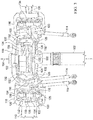
- Rotor system 100 generally comprises a mast 102 that may rotate about a mast axis of rotation 104.
- the rotor system 100 may further comprise a flexural yoke 106 comprising a plurality of arms 108.
- the flexural yoke 106 may comprise composite laminate materials and/or metal.
- each yoke 106 comprises two arms 108 that are each generally configured for connection to a rotor blade and/or airfoil.
- two yokes 106 are vertically stacked and angularly offset relative to each other to create the four-arm configuration shown.
- the arms 108 may be substantially enveloped by associated cuffs 110.
- each arm 108 may be associated with a spanwise axis 112.
- the spanwise axis 112 may be referred to as a pitch axis and/or a feathering axis about which the arms 108, cuffs 110, and/or rotor blades may rotate and/or twist in response to environmental, operational, and/or control perturbations.
- a pitch change about this spanwise axis 112 of the cuffs 110 and/or rotor blades may be adjusted by vertically translating a pitch link 114 that is pivotally linked to a pitch horn 116 attached to the cuff 110.
- the rotor system 100 may further comprise a shear bearing 120 that may generally comprise a four bar linkage connected to each of an arm 108 and an associated cuff 110.
- the shear bearing 120 may comprise an upper link 122, a lower link 124, two forward links 126, and two rear links 128.
- a plurality of bearings 130 may be utilized in concert with pins 132 for joining the components of the four bar linkage.
- the bearings 130 may comprise elastomeric components configured to return the system to a neutral pitch.
- the upper link 122 and the lower link 124 may be pinned to the pitch horn 116 and the pitch horn 116 may be attached to and/or substantially carry the cuff 110.
- the shear bearing 120 may further comprise a grip 134 connected between the forward links 126 and the rear links 128 utilizing bearings 130 and pins 132.
- the grip 134 may generally extend around the arm 108 and may be sufficiently rigid to snugly retain damper pads 136 between the grip 134 and the arm 108 on both an upper side of the arm 108 and a lower side of the arm 108.
- the above-described mechanical linkages of the shear bearing 120 may be configured to primarily transmit rotational forces about the spanwise axis 112 between the arms 108 of the flexural yoke 106 and the pitch horn 116.
- the shear bearing 120 may additionally and/or alternatively be connected directly to the cuff 110 and/or pitch link 114.
- the rotor system 100 may rotate the flexure yoke 106 and the related components about the mast axis of rotation 104.
- a rotational force about the spanwise axis 112 that may tend to change a pitch of the rotor blade and/or cause feathering of the rotor blade may be imparted to at least one of the rotor blade associated with an arm 108, the cuff 110 associated with the arm 108, and/or the pitch horn 116 associated with the arm 108.
- the rotational force applied to the rotor blade and/or the cuff 110 may be a result of air loads generated in flight or other environmental condition while the rotational force applied to the pitch horn 116 may be the result of a control input to the rotor system 100 via the pitch link 114.
- the shear bearing 120 may be configured to transfer and/or partially absorb the movement and/or energy related to the forces.
- the shear bearing 120 may be configured to receive rotational inputs about the spanwise axis 112, alter a position of the four bar linkage of the shear bearing 120, and resultantly transmit rotational movement and/or forces to the arm 108 via the grip 134 and associated damper pads 136.
- the kinematic behavior of the four bar linkage of the shear bearing 120 may be described as converting rotational inputs from the pitch horn 116 into relative translational movements of the upper and lower links 122, 124 relative to the grip 134.
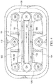
- a schematic cut-away view of the shear bearing 120 is as viewed from a relatively inboard location and looking generally radially outward along the spanwise axis 112.
- the grip 134 being pinned between the forward and rear links 126, 128 of the four bar linkage, the above-described relative translational movements are effectively converted from the translational movements to a rotational movement of the arm 108 about a center of rotation 140 of the shear bearing 120.
- the center of rotation 140 may be positioned substantially coincident with the spanwise axis 112. In some cases, the center of rotation 140 may also be a point about which the four bar linkage of the shear bearing 120 cocks or otherwise is racked out of plane as a function of one or more of the bearings 130 accommodating spherical and/or orbiting movement between interconnected links of the four bar linkage. In some cases, one or more of the bearings 130 may be configured as a spherical bearing while other bearings 130 are configured to substantially limit movement to rotation about the pins 132. In some cases, an elasticity and/or spring rating of the bearings 130 may be relatively high as compared to other components of the shear bearing.
- the bearings 130 may be selected to have spring rates that do not substantially interfere with an effectiveness of the damper pads 136 and/or any other primary damping component.
- providing the damper pads 136 directly on the arm 108 may provide a more consistent damping functionality that is substantially independent of any flapping and/or pitching of the arm 108.
- the utilization of the damper pads 136 in the manner described above may negate a need for a separate fluid damper in the rotor system 100.
- Figure 4 shows that the shear bearing 120 may require no centrally located aperture, cavity, and/or recess in the flexural yoke 106 for the purpose of accommodating a shear bearing within the aperture, cavity, and/or recess because the accommodation of vertical shear in the rotor system 100 is achieved by applying forces to the outside and/or continuous upper and/or lower surfaces of the flexural yoke 106.
- the systems and methods disclosed may prevent the need for a through hole or aperture in a yoke such as hole 202 of Figure 2 that may otherwise be provided to accommodate a typical shear bearing that may comprise a center of rotation located substantially similarly as the center of rotation 140.
- the rotor system 100 may comprise a flexural yoke comprising only holes for accommodating passage of a mast therethrough and/or for accepting bolts and/or other fasteners associated with securing the flexural yoke 106 to the mast 102.
- a flexural yoke 106 that comprises a composite layup of materials may significantly strengthen the yoke 106 in tension along a load bearing continuous fiber that extends between opposing yoke arms 108, decrease an overall mass, decrease an overall radial footprint, and/or otherwise improve a performance characteristic of the flexural yoke 106.
- shear bearing 120 and associated components and configurations are described above in the context of a rotor system 100 for a helicopter, the shear bearing 120 and the rotor system 100 may be applied to any other suitable rotor related application.
- a fixed wing aircraft in which a pitch of a propeller may be adjusted e.g. constant speed propeller systems
- any other craft or device that may selectively control a pitch and/or feathering of a rotor blade may benefit from utilization of the shear bearing 120 and/or rotor system 100.
- R R l +k*(R u -R l ), wherein k is a variable ranging from 1 percent to 100 percent with a 1 percent increment, i.e., k is 1 percent, 2 percent, 3 percent, 4 percent, 5 percent, ..., 50 percent, 51 percent, 52 percent, ..., 95 percent, 96 percent, 97 percent, 98 percent, 99 percent, or 100 percent. Unless otherwise stated, the term "about” shall mean plus or minus 10 percent of the subsequent value. Moreover, any numerical range defined by two R numbers as defined in the above is also specifically disclosed.
Landscapes
- Engineering & Computer Science (AREA)
- Mechanical Engineering (AREA)
- Aviation & Aerospace Engineering (AREA)
- Vibration Prevention Devices (AREA)
- Wind Motors (AREA)
- Support Of The Bearing (AREA)
- Vibration Dampers (AREA)
Claims (15)
- Système de rotor (100), comprenant:un étrier flexible (106); etun palier de cisaillement (120) configuré de manière à effectuer au moins soit une transmission de forces à l'étrier flexible (106), soit une réception de forces à partir de l'étrier flexible (106), dans lequel le palier de cisaillement (120) comprend:une liaison à quatre barres comprenant un premier ensemble de biellettes opposées comprenant une biellette avant (126) et une biellette arrière (128), et un second ensemble de biellettes opposées comprenant une biellette supérieure (122) et une biellette inférieure (124), la biellette avant (126) étant connectée à la biellette supérieure avec une première broche (132) et à la biellette inférieure avec une deuxième broche (132), la biellette arrière (128) étant connectée à la biellette supérieure (122) avec une troisième broche (132) et à la biellette inférieure (124) avec une quatrième broche (132), la biellette avant étant rotative autour de la première broche et de la deuxième broche, la biellette arrière étant rotative autour de la troisième broche et de la quatrième broche, la biellette supérieure étant rotative autour de la première broche et de la troisième broche, et la biellette inférieure étant rotative autour de la deuxième broche et de la quatrième broche; etune poignée (134) configurée de manière à retenir l'étrier flexible (106), la poignée (134) étant connectée à et positionnée entre le premier ensemble de biellettes opposées (126, 128) de la liaison à quatre barres.
- Système de rotor (100) selon la revendication 1, dans lequel l'étrier (106) est dépourvu de cavités pour recevoir le palier de cisaillement (120).
- Système de rotor (100) selon la revendication 1, dans lequel un centre de rotation (140) du palier de cisaillement (120) est sensiblement coïncident avec un axe dans le sens de l'envergure (112) de l'étrier (106).
- Système de rotor (100) selon la revendication 1, comprenant en outre un tampon (136) disposé sur une surface de l'étrier (106).
- Système de rotor (100) selon la revendication 1, dans lequel l'étrier flexible (106) comprend un étrier composite.
- Système de rotor (100) selon la revendication 1, dans lequel les seules ouvertures dans l'étrier (106) sont configurées de manière à exécuter au moins soit l'acceptation d'un mât (102) à travers celui-ci soit la fixation de l'étrier (106) à un mât (102).
- Système de rotor (100) selon la revendication 1, dans lequel le palier de cisaillement (120) comprend un tampon (136), dans lequel, en particulier, le tampon est un coussinet d'amortissement (136) qui est attaché à la poignée (134).
- Système de rotor (100) selon la revendication 1, dans lequel le palier de cisaillement (120) comprend un palier élastomère.
- Système de rotor (100) selon la revendication 1, dans lequel la liaison à quatre barres comprend des paliers (130).
- Système de rotor (100) selon la revendication 9, dans lequel au moins un des paliers (130) est configuré comme un palier sphérique.
- Système de rotor (100) selon la revendication 1, dans lequel le palier de cisaillement (120) est configuré de manière à réaliser une connexion externe avec l'étrier (106).
- Système de rotor (100) selon la revendication 1, dans lequel le palier de cisaillement (120) est configuré de manière à réaliser une connexion avec un levier de pas (116).
- Système de rotor (100) selon la revendication 1, dans lequel le palier de cisaillement (120) est configuré de manière à transmettre des forces entre l'étrier flexible (106) et un levier de pas (116).
- Système de rotor (100) selon la revendication 1, dans lequel le premier ensemble de biellettes opposées (126, 128) comprend quatre biellettes.
- Système de rotor (100) selon la revendication 4, dans lequel le tampon est retenu spatialement par rapport à l'étrier (106) par le palier de cisaillement (120).
Applications Claiming Priority (1)
| Application Number | Priority Date | Filing Date | Title |
|---|---|---|---|
| US13/778,803 US9457897B2 (en) | 2013-02-27 | 2013-02-27 | Rotor system shear bearing |
Publications (4)
| Publication Number | Publication Date |
|---|---|
| EP2772431A2 EP2772431A2 (fr) | 2014-09-03 |
| EP2772431A3 EP2772431A3 (fr) | 2014-12-24 |
| EP2772431B1 true EP2772431B1 (fr) | 2017-08-09 |
| EP2772431B8 EP2772431B8 (fr) | 2017-10-25 |
Family
ID=48190752
Family Applications (1)
| Application Number | Title | Priority Date | Filing Date |
|---|---|---|---|
| EP13165399.0A Active EP2772431B8 (fr) | 2013-02-27 | 2013-04-25 | Palier de cisaillement de système de rotor |
Country Status (2)
| Country | Link |
|---|---|
| US (1) | US9457897B2 (fr) |
| EP (1) | EP2772431B8 (fr) |
Families Citing this family (4)
| Publication number | Priority date | Publication date | Assignee | Title |
|---|---|---|---|---|
| EP2772430B1 (fr) * | 2013-02-27 | 2016-06-29 | AIRBUS HELICOPTERS DEUTSCHLAND GmbH | Bras de flexion cruciforme d'une partie et procédé de fabrication d'un tel bras |
| US10000283B2 (en) * | 2013-03-14 | 2018-06-19 | William L. Hinks | Negative spring compensation for elastomeric bearing torque |
| KR102027226B1 (ko) * | 2017-06-16 | 2019-10-01 | 에어버스 헬리콥터스 | 후방 존에서 돌기물을 가지는 항공기 로터 블레이드 슬리브와, 그러한 슬리브가 제공된 로터 |
| US10494090B2 (en) * | 2017-09-08 | 2019-12-03 | Bell Helicopter Textron Inc. | Rotor hub with structural reinforcements |
Family Cites Families (7)
| Publication number | Priority date | Publication date | Assignee | Title |
|---|---|---|---|---|
| US3874815A (en) | 1973-11-15 | 1975-04-01 | Boeing Co | Rotary head assembly for rotary wing aircraft |
| US4093400A (en) | 1976-12-15 | 1978-06-06 | United Technologies Corporation | Cross beam rotor |
| USRE30713E (en) | 1979-08-01 | 1981-08-18 | United Technologies Corp. | Cross beam rotor |
| FR2778165B1 (fr) | 1998-04-29 | 2000-07-13 | Eurocopter France | Rotor sans articulation avec demi-paliers precomprimes d'appui des manchettes de pied de pale sur des lames torsibles d'emplanture des pales |
| EP2032427B1 (fr) | 2006-06-20 | 2015-08-12 | Bell Helicopter Textron Inc. | Palier à force centrifuge avec moment de tangage stable |
| US7677584B2 (en) * | 2006-10-10 | 2010-03-16 | Actuant Corporation | Motorized collapsible step |
| CA2749118C (fr) | 2009-01-19 | 2015-09-08 | Bell Helicopter Textron Inc. | Configuration de rotor rigide dans son plan |
-
2013
- 2013-02-27 US US13/778,803 patent/US9457897B2/en active Active
- 2013-04-25 EP EP13165399.0A patent/EP2772431B8/fr active Active
Non-Patent Citations (1)
| Title |
|---|
| None * |
Also Published As
| Publication number | Publication date |
|---|---|
| US20140241886A1 (en) | 2014-08-28 |
| EP2772431A3 (fr) | 2014-12-24 |
| US9457897B2 (en) | 2016-10-04 |
| EP2772431B8 (fr) | 2017-10-25 |
| EP2772431A2 (fr) | 2014-09-03 |
Similar Documents
| Publication | Publication Date | Title |
|---|---|---|
| US8444382B2 (en) | Rotor hub for use with high-inertia blades | |
| US9718542B2 (en) | Blade attachment for a bearingless rotor of a helicopter | |
| EP2832640B1 (fr) | Flexion composite pour système de rotor basculant | |
| US3880551A (en) | Rotary head assembly for rotary wing aircraft | |
| EP2653383B1 (fr) | Pale d'un rotor sans palier d'un hélicoptère | |
| EP2778054B1 (fr) | Système de rotor composite utilisant deux culasses en porte-à-faux de style piste de roulement | |
| EP2570346B1 (fr) | Rotor avec pales comprenant une coque de pale extérieure et élément structural interne | |
| EP3333074B1 (fr) | Systèmes de rotor orientable souple dans le plan | |
| US10723450B2 (en) | Passive pitch angle adjustment apparatus | |
| CN109533317B (zh) | 一种刚性旋翼桨叶根部构型 | |
| US9657816B2 (en) | Drive link for tiltrotor rotor system | |
| EP2772431B1 (fr) | Palier de cisaillement de système de rotor | |
| GB1582411A (en) | Beam rotor | |
| US9469399B2 (en) | Separable blade attachment for a bearingless rotor of a helicopter | |
| KR20130117687A (ko) | 헬리콥터의 무베어링 로터용 공기역학적 블레이드 부착장치 | |
| US9623963B2 (en) | Partly cruciform flexbeam and method of manufacturing such a flexbeam | |
| US11440651B1 (en) | Spherical bearing centrifugal force retention link | |
| WO2004045948A1 (fr) | Pale rotative |
Legal Events
| Date | Code | Title | Description |
|---|---|---|---|
| PUAI | Public reference made under article 153(3) epc to a published international application that has entered the european phase |
Free format text: ORIGINAL CODE: 0009012 |
|
| 17P | Request for examination filed |
Effective date: 20130425 |
|
| AK | Designated contracting states |
Kind code of ref document: A2 Designated state(s): AL AT BE BG CH CY CZ DE DK EE ES FI FR GB GR HR HU IE IS IT LI LT LU LV MC MK MT NL NO PL PT RO RS SE SI SK SM TR |
|
| AX | Request for extension of the european patent |
Extension state: BA ME |
|
| PUAL | Search report despatched |
Free format text: ORIGINAL CODE: 0009013 |
|
| AK | Designated contracting states |
Kind code of ref document: A3 Designated state(s): AL AT BE BG CH CY CZ DE DK EE ES FI FR GB GR HR HU IE IS IT LI LT LU LV MC MK MT NL NO PL PT RO RS SE SI SK SM TR |
|
| AX | Request for extension of the european patent |
Extension state: BA ME |
|
| RIC1 | Information provided on ipc code assigned before grant |
Ipc: B64C 27/35 20060101AFI20141118BHEP Ipc: B64C 27/33 20060101ALI20141118BHEP Ipc: B64C 27/48 20060101ALI20141118BHEP |
|
| GRAP | Despatch of communication of intention to grant a patent |
Free format text: ORIGINAL CODE: EPIDOSNIGR1 |
|
| INTG | Intention to grant announced |
Effective date: 20170407 |
|
| GRAS | Grant fee paid |
Free format text: ORIGINAL CODE: EPIDOSNIGR3 |
|
| GRAA | (expected) grant |
Free format text: ORIGINAL CODE: 0009210 |
|
| AK | Designated contracting states |
Kind code of ref document: B1 Designated state(s): AL AT BE BG CH CY CZ DE DK EE ES FI FR GB GR HR HU IE IS IT LI LT LU LV MC MK MT NL NO PL PT RO RS SE SI SK SM TR |
|
| REG | Reference to a national code |
Ref country code: GB Ref legal event code: FG4D |
|
| REG | Reference to a national code |
Ref country code: CH Ref legal event code: EP Ref country code: AT Ref legal event code: REF Ref document number: 916499 Country of ref document: AT Kind code of ref document: T Effective date: 20170815 |
|
| REG | Reference to a national code |
Ref country code: IE Ref legal event code: FG4D |
|
| REG | Reference to a national code |
Ref country code: DE Ref legal event code: R096 Ref document number: 602013024639 Country of ref document: DE |
|
| RIN2 | Information on inventor provided after grant (corrected) |
Inventor name: SUTTON, DREW Inventor name: FRANK B. STAMPS |
|
| REG | Reference to a national code |
Ref country code: NL Ref legal event code: MP Effective date: 20170809 |
|
| REG | Reference to a national code |
Ref country code: LT Ref legal event code: MG4D |
|
| REG | Reference to a national code |
Ref country code: AT Ref legal event code: MK05 Ref document number: 916499 Country of ref document: AT Kind code of ref document: T Effective date: 20170809 |
|
| PG25 | Lapsed in a contracting state [announced via postgrant information from national office to epo] |
Ref country code: HR Free format text: LAPSE BECAUSE OF FAILURE TO SUBMIT A TRANSLATION OF THE DESCRIPTION OR TO PAY THE FEE WITHIN THE PRESCRIBED TIME-LIMIT Effective date: 20170809 Ref country code: NL Free format text: LAPSE BECAUSE OF FAILURE TO SUBMIT A TRANSLATION OF THE DESCRIPTION OR TO PAY THE FEE WITHIN THE PRESCRIBED TIME-LIMIT Effective date: 20170809 Ref country code: SE Free format text: LAPSE BECAUSE OF FAILURE TO SUBMIT A TRANSLATION OF THE DESCRIPTION OR TO PAY THE FEE WITHIN THE PRESCRIBED TIME-LIMIT Effective date: 20170809 Ref country code: AT Free format text: LAPSE BECAUSE OF FAILURE TO SUBMIT A TRANSLATION OF THE DESCRIPTION OR TO PAY THE FEE WITHIN THE PRESCRIBED TIME-LIMIT Effective date: 20170809 Ref country code: NO Free format text: LAPSE BECAUSE OF FAILURE TO SUBMIT A TRANSLATION OF THE DESCRIPTION OR TO PAY THE FEE WITHIN THE PRESCRIBED TIME-LIMIT Effective date: 20171109 Ref country code: FI Free format text: LAPSE BECAUSE OF FAILURE TO SUBMIT A TRANSLATION OF THE DESCRIPTION OR TO PAY THE FEE WITHIN THE PRESCRIBED TIME-LIMIT Effective date: 20170809 Ref country code: LT Free format text: LAPSE BECAUSE OF FAILURE TO SUBMIT A TRANSLATION OF THE DESCRIPTION OR TO PAY THE FEE WITHIN THE PRESCRIBED TIME-LIMIT Effective date: 20170809 |
|
| PG25 | Lapsed in a contracting state [announced via postgrant information from national office to epo] |
Ref country code: GR Free format text: LAPSE BECAUSE OF FAILURE TO SUBMIT A TRANSLATION OF THE DESCRIPTION OR TO PAY THE FEE WITHIN THE PRESCRIBED TIME-LIMIT Effective date: 20171110 Ref country code: LV Free format text: LAPSE BECAUSE OF FAILURE TO SUBMIT A TRANSLATION OF THE DESCRIPTION OR TO PAY THE FEE WITHIN THE PRESCRIBED TIME-LIMIT Effective date: 20170809 Ref country code: PL Free format text: LAPSE BECAUSE OF FAILURE TO SUBMIT A TRANSLATION OF THE DESCRIPTION OR TO PAY THE FEE WITHIN THE PRESCRIBED TIME-LIMIT Effective date: 20170809 Ref country code: ES Free format text: LAPSE BECAUSE OF FAILURE TO SUBMIT A TRANSLATION OF THE DESCRIPTION OR TO PAY THE FEE WITHIN THE PRESCRIBED TIME-LIMIT Effective date: 20170809 Ref country code: BG Free format text: LAPSE BECAUSE OF FAILURE TO SUBMIT A TRANSLATION OF THE DESCRIPTION OR TO PAY THE FEE WITHIN THE PRESCRIBED TIME-LIMIT Effective date: 20171109 Ref country code: RS Free format text: LAPSE BECAUSE OF FAILURE TO SUBMIT A TRANSLATION OF THE DESCRIPTION OR TO PAY THE FEE WITHIN THE PRESCRIBED TIME-LIMIT Effective date: 20170809 Ref country code: IS Free format text: LAPSE BECAUSE OF FAILURE TO SUBMIT A TRANSLATION OF THE DESCRIPTION OR TO PAY THE FEE WITHIN THE PRESCRIBED TIME-LIMIT Effective date: 20171209 |
|
| REG | Reference to a national code |
Ref country code: FR Ref legal event code: PLFP Year of fee payment: 6 |
|
| PG25 | Lapsed in a contracting state [announced via postgrant information from national office to epo] |
Ref country code: DK Free format text: LAPSE BECAUSE OF FAILURE TO SUBMIT A TRANSLATION OF THE DESCRIPTION OR TO PAY THE FEE WITHIN THE PRESCRIBED TIME-LIMIT Effective date: 20170809 Ref country code: RO Free format text: LAPSE BECAUSE OF FAILURE TO SUBMIT A TRANSLATION OF THE DESCRIPTION OR TO PAY THE FEE WITHIN THE PRESCRIBED TIME-LIMIT Effective date: 20170809 Ref country code: CZ Free format text: LAPSE BECAUSE OF FAILURE TO SUBMIT A TRANSLATION OF THE DESCRIPTION OR TO PAY THE FEE WITHIN THE PRESCRIBED TIME-LIMIT Effective date: 20170809 |
|
| REG | Reference to a national code |
Ref country code: DE Ref legal event code: R097 Ref document number: 602013024639 Country of ref document: DE |
|
| PG25 | Lapsed in a contracting state [announced via postgrant information from national office to epo] |
Ref country code: SK Free format text: LAPSE BECAUSE OF FAILURE TO SUBMIT A TRANSLATION OF THE DESCRIPTION OR TO PAY THE FEE WITHIN THE PRESCRIBED TIME-LIMIT Effective date: 20170809 Ref country code: SM Free format text: LAPSE BECAUSE OF FAILURE TO SUBMIT A TRANSLATION OF THE DESCRIPTION OR TO PAY THE FEE WITHIN THE PRESCRIBED TIME-LIMIT Effective date: 20170809 Ref country code: EE Free format text: LAPSE BECAUSE OF FAILURE TO SUBMIT A TRANSLATION OF THE DESCRIPTION OR TO PAY THE FEE WITHIN THE PRESCRIBED TIME-LIMIT Effective date: 20170809 |
|
| PLBE | No opposition filed within time limit |
Free format text: ORIGINAL CODE: 0009261 |
|
| STAA | Information on the status of an ep patent application or granted ep patent |
Free format text: STATUS: NO OPPOSITION FILED WITHIN TIME LIMIT |
|
| 26N | No opposition filed |
Effective date: 20180511 |
|
| PG25 | Lapsed in a contracting state [announced via postgrant information from national office to epo] |
Ref country code: SI Free format text: LAPSE BECAUSE OF FAILURE TO SUBMIT A TRANSLATION OF THE DESCRIPTION OR TO PAY THE FEE WITHIN THE PRESCRIBED TIME-LIMIT Effective date: 20170809 |
|
| PG25 | Lapsed in a contracting state [announced via postgrant information from national office to epo] |
Ref country code: MC Free format text: LAPSE BECAUSE OF FAILURE TO SUBMIT A TRANSLATION OF THE DESCRIPTION OR TO PAY THE FEE WITHIN THE PRESCRIBED TIME-LIMIT Effective date: 20170809 |
|
| REG | Reference to a national code |
Ref country code: CH Ref legal event code: PL |
|
| REG | Reference to a national code |
Ref country code: BE Ref legal event code: MM Effective date: 20180430 |
|
| REG | Reference to a national code |
Ref country code: IE Ref legal event code: MM4A |
|
| PG25 | Lapsed in a contracting state [announced via postgrant information from national office to epo] |
Ref country code: LU Free format text: LAPSE BECAUSE OF NON-PAYMENT OF DUE FEES Effective date: 20180425 |
|
| PG25 | Lapsed in a contracting state [announced via postgrant information from national office to epo] |
Ref country code: LI Free format text: LAPSE BECAUSE OF NON-PAYMENT OF DUE FEES Effective date: 20180430 Ref country code: CH Free format text: LAPSE BECAUSE OF NON-PAYMENT OF DUE FEES Effective date: 20180430 Ref country code: BE Free format text: LAPSE BECAUSE OF NON-PAYMENT OF DUE FEES Effective date: 20180430 |
|
| PG25 | Lapsed in a contracting state [announced via postgrant information from national office to epo] |
Ref country code: IE Free format text: LAPSE BECAUSE OF NON-PAYMENT OF DUE FEES Effective date: 20180425 |
|
| PG25 | Lapsed in a contracting state [announced via postgrant information from national office to epo] |
Ref country code: MT Free format text: LAPSE BECAUSE OF NON-PAYMENT OF DUE FEES Effective date: 20180425 |
|
| PG25 | Lapsed in a contracting state [announced via postgrant information from national office to epo] |
Ref country code: TR Free format text: LAPSE BECAUSE OF FAILURE TO SUBMIT A TRANSLATION OF THE DESCRIPTION OR TO PAY THE FEE WITHIN THE PRESCRIBED TIME-LIMIT Effective date: 20170809 |
|
| PG25 | Lapsed in a contracting state [announced via postgrant information from national office to epo] |
Ref country code: HU Free format text: LAPSE BECAUSE OF FAILURE TO SUBMIT A TRANSLATION OF THE DESCRIPTION OR TO PAY THE FEE WITHIN THE PRESCRIBED TIME-LIMIT; INVALID AB INITIO Effective date: 20130425 Ref country code: PT Free format text: LAPSE BECAUSE OF FAILURE TO SUBMIT A TRANSLATION OF THE DESCRIPTION OR TO PAY THE FEE WITHIN THE PRESCRIBED TIME-LIMIT Effective date: 20170809 |
|
| PG25 | Lapsed in a contracting state [announced via postgrant information from national office to epo] |
Ref country code: CY Free format text: LAPSE BECAUSE OF FAILURE TO SUBMIT A TRANSLATION OF THE DESCRIPTION OR TO PAY THE FEE WITHIN THE PRESCRIBED TIME-LIMIT Effective date: 20170809 Ref country code: MK Free format text: LAPSE BECAUSE OF NON-PAYMENT OF DUE FEES Effective date: 20170809 |
|
| PG25 | Lapsed in a contracting state [announced via postgrant information from national office to epo] |
Ref country code: AL Free format text: LAPSE BECAUSE OF FAILURE TO SUBMIT A TRANSLATION OF THE DESCRIPTION OR TO PAY THE FEE WITHIN THE PRESCRIBED TIME-LIMIT Effective date: 20170809 |
|
| P01 | Opt-out of the competence of the unified patent court (upc) registered |
Effective date: 20230602 |
|
| PGFP | Annual fee paid to national office [announced via postgrant information from national office to epo] |
Ref country code: IT Payment date: 20230419 Year of fee payment: 11 Ref country code: FR Payment date: 20230425 Year of fee payment: 11 Ref country code: DE Payment date: 20230427 Year of fee payment: 11 |
|
| PGFP | Annual fee paid to national office [announced via postgrant information from national office to epo] |
Ref country code: GB Payment date: 20230427 Year of fee payment: 11 |