EP2772416A2 - Fahrzeugaufbau - Google Patents
Fahrzeugaufbau Download PDFInfo
- Publication number
- EP2772416A2 EP2772416A2 EP20140156866 EP14156866A EP2772416A2 EP 2772416 A2 EP2772416 A2 EP 2772416A2 EP 20140156866 EP20140156866 EP 20140156866 EP 14156866 A EP14156866 A EP 14156866A EP 2772416 A2 EP2772416 A2 EP 2772416A2
- Authority
- EP
- European Patent Office
- Prior art keywords
- tub
- mould
- roof
- flexible
- rigid
- Prior art date
- Legal status (The legal status is an assumption and is not a legal conclusion. Google has not performed a legal analysis and makes no representation as to the accuracy of the status listed.)
- Granted
Links
Images


Classifications
-
- B—PERFORMING OPERATIONS; TRANSPORTING
- B62—LAND VEHICLES FOR TRAVELLING OTHERWISE THAN ON RAILS
- B62D—MOTOR VEHICLES; TRAILERS
- B62D23/00—Combined superstructure and frame, i.e. monocoque constructions
-
- B—PERFORMING OPERATIONS; TRANSPORTING
- B29—WORKING OF PLASTICS; WORKING OF SUBSTANCES IN A PLASTIC STATE IN GENERAL
- B29C—SHAPING OR JOINING OF PLASTICS; SHAPING OF MATERIAL IN A PLASTIC STATE, NOT OTHERWISE PROVIDED FOR; AFTER-TREATMENT OF THE SHAPED PRODUCTS, e.g. REPAIRING
- B29C70/00—Shaping composites, i.e. plastics material comprising reinforcements, fillers or preformed parts, e.g. inserts
- B29C70/04—Shaping composites, i.e. plastics material comprising reinforcements, fillers or preformed parts, e.g. inserts comprising reinforcements only, e.g. self-reinforcing plastics
- B29C70/28—Shaping operations therefor
- B29C70/30—Shaping by lay-up, i.e. applying fibres, tape or broadsheet on a mould, former or core; Shaping by spray-up, i.e. spraying of fibres on a mould, former or core
- B29C70/34—Shaping by lay-up, i.e. applying fibres, tape or broadsheet on a mould, former or core; Shaping by spray-up, i.e. spraying of fibres on a mould, former or core and shaping or impregnating by compression, i.e. combined with compressing after the lay-up operation
- B29C70/342—Shaping by lay-up, i.e. applying fibres, tape or broadsheet on a mould, former or core; Shaping by spray-up, i.e. spraying of fibres on a mould, former or core and shaping or impregnating by compression, i.e. combined with compressing after the lay-up operation using isostatic pressure
-
- B—PERFORMING OPERATIONS; TRANSPORTING
- B29—WORKING OF PLASTICS; WORKING OF SUBSTANCES IN A PLASTIC STATE IN GENERAL
- B29C—SHAPING OR JOINING OF PLASTICS; SHAPING OF MATERIAL IN A PLASTIC STATE, NOT OTHERWISE PROVIDED FOR; AFTER-TREATMENT OF THE SHAPED PRODUCTS, e.g. REPAIRING
- B29C70/00—Shaping composites, i.e. plastics material comprising reinforcements, fillers or preformed parts, e.g. inserts
- B29C70/68—Shaping composites, i.e. plastics material comprising reinforcements, fillers or preformed parts, e.g. inserts by incorporating or moulding on preformed parts, e.g. inserts or layers, e.g. foam blocks
- B29C70/86—Incorporated in coherent impregnated reinforcing layers, e.g. by winding
-
- B—PERFORMING OPERATIONS; TRANSPORTING
- B62—LAND VEHICLES FOR TRAVELLING OTHERWISE THAN ON RAILS
- B62D—MOTOR VEHICLES; TRAILERS
- B62D29/00—Superstructures, understructures, or sub-units thereof, characterised by the material thereof
- B62D29/04—Superstructures, understructures, or sub-units thereof, characterised by the material thereof predominantly of synthetic material
- B62D29/046—Combined superstructure and frame, i.e. monocoque constructions
-
- B—PERFORMING OPERATIONS; TRANSPORTING
- B29—WORKING OF PLASTICS; WORKING OF SUBSTANCES IN A PLASTIC STATE IN GENERAL
- B29C—SHAPING OR JOINING OF PLASTICS; SHAPING OF MATERIAL IN A PLASTIC STATE, NOT OTHERWISE PROVIDED FOR; AFTER-TREATMENT OF THE SHAPED PRODUCTS, e.g. REPAIRING
- B29C43/00—Compression moulding, i.e. applying external pressure to flow the moulding material; Apparatus therefor
- B29C43/32—Component parts, details or accessories; Auxiliary operations
- B29C43/36—Moulds for making articles of definite length, i.e. discrete articles
- B29C43/3642—Bags, bleeder sheets or cauls for isostatic pressing
- B29C2043/3652—Elastic moulds or mould parts, e.g. cores or inserts
Definitions
- This invention relates to manufacturing vehicle bodies.
- a crucial part of automobile design is making the body of the vehicle sufficiently strong to protect the occupants in the event of a crash, and sufficiently stiff to prevent bending or torsion of the body from affecting the vehicle's handling.
- One way of making a relatively strong body is to use a composite tub, for example as described in EP 2 534 029 A .
- a typical composite tub has a floor, sills upstanding from the floor along the sides of the floor and front and rear bulkheads upstanding from the floor at the front and rear of the floor.
- the vehicle's running gear and powertrain can be attached to the front and rear bulkheads.
- this structure may be sufficient, but for a passenger car or an enclosed racing car it is normally desirable to fit a roof to the tub. This is normally done by forming the roof separately and then attaching it to the tub: either by bolting it in place or by bonding it to the tub using adhesive. Using bolts is undesirable because it introduces additional weight and concentrates the loads between the roof and the tub on the areas to which the bolts are attached.
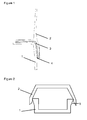
- Figure 1 shows an adhesive join between a tub and a roof.
- Figure 1 is a cross-section through the join, showing part of a tub 1, part of a roof 2, and a layer 3 of adhesive between the tub and the roof.
- Joints of this type suffer from a number of limitations.
- a method for forming a vehicle body comprising: forming a rigid tub; mating the rigid tub to a first mould for a superstructure of the vehicle body; and subsequently rigidifying material in the first mould whilst part of that material is in contact with the tub to thereby form the superstructure of the vehicle body integral with the tub.
- the step of mating the rigid tub to the first mould may comprise locating the tub to the first mould by aligning a datum feature on the tub with a datum feature on the first mould.
- the method may comprise, after the said curing step, attaching a component of the vehicle to the tub with the datum feature on the tub aligned with a datum feature on the component.
- the component may be a part of the running gear or powertrain of the vehicle: for example a suspension carrier or an engine carrier.
- the said material may comprise a superstructure portion and a bonding portion integral with the superstructure portion and in contact with the tub.
- the superstructure portion may be intended to form a roof of the vehicle.
- the bonding portion may overlap the tub for bonding the superstructure portion to the tub.
- the said material may be a fibre-reinforced material. Reinforcing fibres may bridge between the superstructure portion and the bonding portion.
- the first mould may comprise a flexible portion.
- the rigidifying step may comprise causing the flexible portion to flex so as to bear against at least part of the bonding portion.
- the flexible portion may press at least part of the bonding portion against the tub.
- the first mould may further comprise a non-flexible portion a surface of which defines the shape of at least part of the superstructure portion.
- the flexible portion may comprise a distal region and a proximal region located between the distal region and the superstructure portion, and the distal region may have greater freedom of movement than the proximal region.
- the rigidifying step may comprise applying pressure to the flexible portion to consolidate the bonding portion against the tub.
- the bonding portion is preferably thinner at an end remote from the superstructure portion than at an end proximal to the superstructure portion.
- a tapering profile may be achieved by staggering the termination points of sub-layers or fibres of the material of the bonding portion such that they terminate at different distances from the end remote from the superstructure portion.
- the step of forming a rigid tub may comprise: pressing a hollow body of material against the interior of a second mould by means of an inflatable core located within the hollow body; and rigidifying the hollow body with the inflatable core located therein so as to form at least part of the tub; keeping the inflatable core in the hollow body of the tub until the said step of rigidifying material in the first mould; and the said step of rigidifying material in the first mould may comprise applying pressure against the first mould by means of the inflatable core.
- the material of the superstructure may be of a reinforced resin composite material.
- the step of rigidifying material in the first mould may comprise curing the resin.
- the superstructure may be adhered to the tub by the resin. Additional adhesive may be incorporated on the surface of the tub to aid adhesion of the superstructure.
- the material of the superstructure may split such that and a first limb of the material extends from the interface in a first direction over the tub and a second limb of the material extends from the interface in a second direction over the tub.
- the angle between the first and second directions may be between 45° and 135°.
- the first and second limbs of material are preferably pressurised against the tub in directions that deviate from each other by greater than 45°, more preferably greater than 70°.
- a method for forming an integrated structure comprising first and second bodies, the method comprising: forming the first body in a rigid state and subsequently: preparing a mould for the second body, the mould being mated to the first rigid body and the mould comprising a first, rigid zone adjacent to first precursor material for the second body and a second, flexible zone adjacent to second precursor material for the second body; applying pressure against the flexible zone to urge the second precursor material against the first body; and rigidifying the precursor material whilst the second precursor material is in contact with the first body.
- the second, flexible zone may be anchored to the first, rigid zone prior to the step of applying pressure.
- the first and second zones may be parts of a common mould tool.
- the second, flexible zone may be anchored to the first, rigid zone at the boundary of the first body.
- the second, flexible zone may be constituted by one or more flexible plates attached to the first, rigid zone.
- the second, flexible zone may have greater mobility relative to the first body at an end remote from the first, rigid zone than at an end adjacent the first, rigid zone.
- the step of applying pressure may comprise causing the second precursor material to adopt a tapering profile that becomes thinner towards an edge of the second precursor material remote from the first precursor material.
- the precursor material may comprise a resin matrix and a reinforcing component.
- the rigidifying step may comprise bonding the second body to the first body by means of the resin comprised in the precursor material.
- the first body may comprise an adhesive layer.
- the second precursor material may be in contact with the adhesive layer of the first body.
- the step of applying pressure may comprise applying a pressure by means of an inflatable flexible and/or elastic bag bearing against the second, flexible zone.
- the flexible tool may flex relative to the rigid tool.
- the flexible tool does not stretch relative to the rigid tool during the process.
- the flexible tool is incompressible, so it does not change in thickness as pressure is applied during the process.
- a tub is formed so that it is in a rigid state. Then the tub is offered up to a mould for a roof and the roof is moulded integrally with the tub.
- Figure 3 shows a tub for an automobile.
- the tub has a floor 10. Upstanding from the sides of the floor are sills 11, 12. Upstanding from the front and rear of the floor are front and rear bulkheads 13, 14.
- the front bulkhead 13 has attachment points 15 for the front running gear of the vehicle.
- the rear bulkhead may have similar attachment points for the rear running gear. In this way, the tub bridges between the front and rear running gear.
- the vehicle's powertrain can be attached to the front or rear bulkhead. Seats for occupants can be installed inside the tub.
- the tub can be formed of any suitable material, but conveniently it can be formed of a reinforced polymer composite material such as a carbon fibre reinforced polymer (CFRP).
- CFRP carbon fibre reinforced polymer
- the polymer could, for example be an epoxy.
- the polymer could be reinforced with other components such as aramid or glass fibres, or particles.
- the tub could be formed of metal: for example it could be an aluminium box structure. Taking CFRP as an example, the tub can be formed by moulding, for example in the manner described in EP 2 534 029 A .
- figure 4 shows generally (and ignoring any attachment points, which will be described in more detail below) the form of the roof that might be desired to extend from the tub of figure 3 .
- the roof comprises front or "A" pillars 20, 21 which would extend from the front bulkhead 13, rear or “C” pillars 22, 23 which would extend from the rear bulkhead 14 and a top plate 24 which would form a covering for the interior of the tub when the roof was attached to the tub. Windows and doors could be installed in the gaps between the pillars.
- Other designs of roof are possible. For example it is possible to do away with the top plate 24 and replace it with a retractable soft-top or retractable hard-top mechanism.
- the roof is attached to the tub by being moulded integrally with the tub when the tub is already rigid.
- This can involve providing a flexible precursor of the roof, contacting a part of that precursor with the tub whilst that part of the precursor remains flexible and rigidifying the roof precursor.
- the roof precursor may contain resin that is destined to cure to form the matrix of the final roof material; alternatively, resin may be flowed through the roof material during the process.
- the roof material is rigidified and simultaneously bonded to the tub by means of that resin.
- Figure 5 illustrates generally the way in which this can be done.
- Figure 5 shows a cross-section through a tub 30 located in an inverted orientation against a mould 31 for a roof.
- the tub is formed of CFRP.
- each hollow section contains an inflatable bag or semi-rigid core 33 which was inflated during the process of forming the tub in order to force the material of the tub against the exterior mould.
- the material that is to form the roof which in this case is a CFRP precursor such as a pre-preg, is laid up in the roof mould, as indicated at 34. Where the superstructure of the roof meets the tub, at 35, the material of the roof divides so that one part of it 36 extends in one direction over the surface of the tub away from meeting point 35 and one part of it 37 extends in the other direction over the surface of the tub from meeting point 35.
- An inflatable bag or semi-rigid core 38 is located within the cavity 39 defined by the tub and the roof.
- the bag 38 is inflated so as to press the roof material 34 against the roof mould 31.
- the bag 33 in the tub can be pressurised at the same time, and pressure can also be applied if necessary against the exterior of the roof mould.
- the roof material is heated to cause it to cure whilst it is being pressed against the tub.
- the pressure can be released and the mould can be removed from the roof. Curing of the roof material could be initiated or accelerated by conditions other than heat.
- the interior bag is capable of occupying the entire interior volume of the roof and tub.
- a rigid interior roof mould which generally follows the contours of the desired interior surface of the roof, and an inflatable bag could be located between that internal mould and the roof material.
- Figure 6 shows in more detail a cross-section of the interface between the roof and the tub.
- the tub which is rigid and has already been cured, is shown at 50.
- the cross-section of figure 6 is through a hollow region of the tub.
- the hollow region contains an inflatable bag 51 which was used to press the material of the tub against an exterior mould when the tub was being cured.
- the roof is not yet cured.
- the roof is formed from a pre-preg, but it could be formed from non-impregnated fibres through which resin is to be applied after the fibres have been laid up, for example by flowing resin through the fibres during the moulding process.
- the pre-preg or the fibres to form the roof could be laid up in the mould before or after the tub is offered up to the roof mould.
- the pre-preg 52 is laid up in the roof mould 53, 54 before the tub is offered up to the roof mould.
- the superstructure of the roof is in the form of a single monolithic sheet. Where the superstructure meets the tub, at junction 55, the plies of the pre-preg diverge.
- plies 56 of the pre-preg extend in one direction across the surface of the tub.
- Other plies 57 of the pre-preg extend from junction 55 in the opposite direction across the surface of the tub. This provides for a relatively large interface area between the tub and the roof.
- the joint when cured can be highly resistant to peeling forces.
- the angle of divergence may be assessed by considering the average direction of the set of plies in question in a direction perpendicular to the junction 55, or by considering the minimum angle of divergence of any of the plies of each set in directions perpendicular to the junction 55.
- the junction 55 is preferably not outboard of the outermost part of the lip of the tub; and in that condition an angle of divergence less than 90° requires the lip of the tub to overhang a lower part of the tub to which the plies 57 extend.
- the junction 55 is at the outermost point on the top of the tub, plies 56 extend inwards along part or all of a top surface of the tub and plies 57 extend down part or all of the outer side surface of the tub.
- the junction 55 could be at the innermost point on the top of the tub, plies 56 could extend inwards along a top surface of the tub and plies 57 could extend down part or all of the inner side surface of the tub.
- the junction 55 could be between the innermost and outermost points on the top of the tub, and plies 56 and 57 could extend away from each other across the top of the tub and then optionally down one or both of the interior and exterior sides of the tub.
- Vacuum bag 60 could fill the whole of that void, or it could be located between an internal roof mould and the non-cured roof material.
- the internal vacuum bag is located so that when inflated it will press the main structure of the roof (at 52) against the interior of the exterior roof mould 53 and will also press arm 56 of the split ply section against the tub - in this case against an upward-facing surface of the tub.
- the exterior mould tool is formed of two parts 53 and 54.
- Part 53 is a rigid mould tool whose interior surface is shaped to the intended external surface of the roof.
- the rigid mould part 53 could be sufficiently strong to oppose by itself the pressure from internal bag 56, but that could result in the rigid mould part being excessively heavy, and so it is preferred that the rigid mould part is encased in an outer pressure bag 58 that can resist the pressure from the interior of the mould.
- the pressure could be applied by applying suction through a port 59 in the outer bag. That port could contain a one-way valve. When the roof is to be moulded a vacuum can be drawn through port 59.
- Atmospheric pressure in internal bag 60 will then cause that bag to inflate, whilst atmospheric pressure acting on the exterior of external bag 58 will press it against the mould tools 53, 54. It may be advantageous to apply higher than atmospheric pressure to the exterior of the mould tools and/or to the internal bag 56, for example by means of an autoclave.
- Attached to rigid mould tool 53 is a flexible or soft mould tool 54.
- Rigid mould tool 53 defines the exterior surface of the roof where the roof does not overlap the tub.
- Flexible mould tool 54 defines the exterior surface of the roof where arm 57 of the split ply section overlaps the tub.
- the flexible mould tool could, for example, be a plate formed of flexible metal or carbon fibre sheet. Multiple such plates could cover the join between the roof and the tub.
- the flexible mould tool is attached to the rigid mould tool. It could be bolted or clamped to the rigid mould tool; or the two could be integrated, with the flexible mould tool being thinner than the rigid mould tool or separated from it by a pliable hinge region.
- the location of the part of the flexible mould tool that is adjacent the rigid mould tool is defined, by virtue of its proximity to the rigid mould tool. Further from that point 62 the flexible mould tool, which is enveloped by the exterior bag 58, can deform towards the tub when a pressure is applied on it by the exterior bag 58.
- the material 57 of the roof is located between the tub 50 and the flexible tool, so when the flexible tool is deformed towards the tub it presses the roof material against the tub. That pressure could be resisted solely by the tub, or additionally by pressure from the bag 51 that is internal to the cavity of the tub.
- the flexible tool 54 has a number of effects. First, by flexing towards the tub it presses the material of the roof against the tub, consolidating the material to make a good joint between the roof and the tub. Second, the flexible tool can be of a material that is flexible but yet self-supporting and/or stiffer than the roof precursor material, unlike a typical vacuum bag. It may be stiffer than the material of the vacuum bag 58 that bears against it. Such a tool can impose a notably smooth outer surface on the joint between the tub and the roof, which is important if that joint will be exposed or will act as a functional surface on the finished vehicle.
- the flexibility of tool 54 means that it can press the roof material even against undercut regions of the tub, allowing good resistance to peeling loads. Once the roof has been moulded against the tub, if a flexible tool has been used to press the material of the roof against the undercut regions of the tub then the tool can still be lifted away from the tub when the roof is demoulded without the mould being disassembled.
- the roof material that overlaps the tub can have a tapered or "feather edge" profile so that it is thicker adjacent the superstructure and thinner at its distal end 63 remote from the superstructure.
- a tapered profile can be achieved by staggering the ends of the plies of the roof material, so that successive plies are dropped off towards the distal end 63.
- the distal termination of the roof material 57 could be of single-ply thickness.
- pre-preg carbon fibre / resin material to form the roof is laid up in the exterior roof mould 53, 54.
- the interior bag 60 is loaded into the mould space.
- the tub is offered up to the mould so that it sits loosely against arms 56 and 57 of the pre-preg.
- the whole structure is wrapped in outer bag 58.
- An autoclave vacuum is drawn through port 59 to pull the main roof structure against the interior of rigid mould body 53, to pull the wing 56 of the roof material against the top of the tub and to cause flexible tool 54 to flex and thereby press wing 57 of roof material against the exterior of the tub.
- the tub itself could react the loads against it, or bag 51 within the tub could be pressurised to react the loads.
- the structure is heated to cure the resin of the roof material.
- the structure is demoulded by removal of the bags and mould bodies. Bags inside the tub (e.g. bag 51) may be left in situ if desired.
- the resulting structure is a monocoque consisting of a vehicle tub to which a roof has been integrally moulded.
- the roof adheres to the tub by virtue of the resin that reinforces the roof, rather than by supplementary adhesive.
- the roof is formed from a pre-preg, it is the resin present in the pre-preg that adheres the roof to the tub.
- the roof is formed by resin transfer moulding, it is the resin that flows into the laid-up fibres during the moulding process that adheres the roof to the tub.
- Each of the vacuum bags 51, 58, 60 could independently be an inflatable semi-rigid body, e.g. a flexible and/or elastic polyethylene box, or a fully flexible and/or elastic bag. Exterior bag 58, if present, could surround both the roof mould 53, 54 and the tub, or it could surround the roof but seal against the tub.
- the roof could be co-cured on to the tub in the manner described above in any orientation. However, it is convenient for the roof to be moulded to the tub with the tub upside down and sitting on the roof mould, as illustrated in figure 5 . This allows the fibres of the roof to be laid up more easily.
- the tub is fully cured and rigid before the process of curing the roof begins, and preferably before it is offered up to the roof mould.
- the tub could be formed by resin transfer moulding.
- the tub is formed of the same material as the roof, since that gives the greatest stability to the joint between the tub and the roof. It is particularly advantageous if the tub and roof are of composite materials whose matrix material is the same.
- Some or all of the regions of the tub that will make contact with the roof material could be treated before the roof is cured to improve adhesion between the tub and the roof. For example, those regions could be abraded to roughen their exterior surfaces or they could be less than fully loaded with resin so that they are porous and/or have exposed fibre relief at their external surfaces.
- the tub could be augmented with a film of adhesive in the regions where the tub where will make contact with the material of the roof. This could improve the adhesion of the roof to the tub.
- the tub and/or the roof can be formed of any suitable material, and could be of the same or different materials.
- the roof is formed of a polymer-based material, such as a composite material having a polymer matrix.
- the matrix is formed of a material whose curing is initiated or accelerated on application of heat.
- the matrix could be formed of a resin such as an epoxy resin.
- the roof could be formed of a fibre-reinforced material. Conveniently it can be formed of a reinforced polymer composite material such as a carbon fibre reinforced polymer.
- a matrix of the roof material could be reinforced with other components such as aramid or glass fibres, or particles.
- the use of flexible tools for consolidating regions of the roof material that overlap the tub also helps dimensional stability. Because the flexible tools are stiffer than a simple vacuum bag they impose a relatively smooth surface on the parts of the roof that they act against. If those parts include functional surfaces such as door sealing surfaces, that smoothness can improve the effectiveness and reliability of those surfaces. If those parts include surfaces that will be exposed in the final vehicle, that smoothness can improve the aesthetics of those surfaces.
- roof could be monolithic, as shown at 52 in figure 6 .
- Parts of the roof could be hollow. Similar techniques to those described above could be used for attaching to a tub an element that is not a full roof, for example a roll-over protection hoop, or for attaching a structure to a pre-cured component that is not a tub.
- the flexible tools 54 are conveniently made of thin sheets of rigid material such as aluminium, steel or carbon fibre.
- the tools are preferably sufficiently stiff that they are self-supporting and will not buckle when pressed against the roof material and the tub by autoclave pressure, but sufficiently flexible that they will deform inwardly under autoclave pressure to consolidate the roof material against the tub.
- a typical vacuum bag as used in moulding is capable of stretching during the moulding process, especially at elevated temperatures.
- a flexible tool as used in the present process is preferably capable of flexing perpendicular to its major plane, but not capable of stretching in that plane during the moulding process.
- a typical vacuum bag is sufficiently soft that during the moulding process it will flex to conform to local irregularities, such as steps, in the part against which it is pressed.
- the flexible tool is preferably sufficiently stiff that during the moulding process it will not conform to such irregularities.
- the flexible tool could be sufficiently stiff that during the moulding process it cannot adopt a bend radius of less than 5cm, more preferably 20cm.
- the flexible tool is preferably anchored to the rigid tool.
- the rigid tool is preferably held fast with the tub.
- the degree of movement of the flexible tool towards the tub under pressure is preferably dependent on the stiffness of the flexible tool.
- Parts of the flexible tools could be rigid with the exception of a weaker pliable zone at their join to the rigid mould tool (e.g. at 62 in figure 6 ).
- the entire area of the flexible mould tool that interfaces with the roof material could be capable of deforming under autoclave pressure.
- the flexible tools are separate from the external vacuum bag 58 and cannot by themselves support a pressure differential between one side of them and the other.
- the external vacuum bag could be made integral with the flexible tools, so it would have a relatively stiff region where it constitutes the flexible tools and would be more flexible elsewhere.
Landscapes
- Engineering & Computer Science (AREA)
- Chemical & Material Sciences (AREA)
- Mechanical Engineering (AREA)
- Composite Materials (AREA)
- Combustion & Propulsion (AREA)
- Transportation (AREA)
- Architecture (AREA)
- Structural Engineering (AREA)
- Body Structure For Vehicles (AREA)
- Casting Or Compression Moulding Of Plastics Or The Like (AREA)
Priority Applications (1)
| Application Number | Priority Date | Filing Date | Title |
|---|---|---|---|
| EP18163243.1A EP3357796B1 (de) | 2013-02-28 | 2014-02-26 | Fahrzeugaufbau |
Applications Claiming Priority (1)
| Application Number | Priority Date | Filing Date | Title |
|---|---|---|---|
| GBGB1303581.1A GB201303581D0 (en) | 2013-02-28 | 2013-02-28 | Vehicle body |
Related Child Applications (2)
| Application Number | Title | Priority Date | Filing Date |
|---|---|---|---|
| EP18163243.1A Division EP3357796B1 (de) | 2013-02-28 | 2014-02-26 | Fahrzeugaufbau |
| EP18163243.1A Division-Into EP3357796B1 (de) | 2013-02-28 | 2014-02-26 | Fahrzeugaufbau |
Publications (3)
| Publication Number | Publication Date |
|---|---|
| EP2772416A2 true EP2772416A2 (de) | 2014-09-03 |
| EP2772416A3 EP2772416A3 (de) | 2015-06-03 |
| EP2772416B1 EP2772416B1 (de) | 2018-05-02 |
Family
ID=48092266
Family Applications (2)
| Application Number | Title | Priority Date | Filing Date |
|---|---|---|---|
| EP14156866.7A Active EP2772416B1 (de) | 2013-02-28 | 2014-02-26 | Fahrzeugaufbau |
| EP18163243.1A Active EP3357796B1 (de) | 2013-02-28 | 2014-02-26 | Fahrzeugaufbau |
Family Applications After (1)
| Application Number | Title | Priority Date | Filing Date |
|---|---|---|---|
| EP18163243.1A Active EP3357796B1 (de) | 2013-02-28 | 2014-02-26 | Fahrzeugaufbau |
Country Status (3)
| Country | Link |
|---|---|
| US (1) | US9387884B2 (de) |
| EP (2) | EP2772416B1 (de) |
| GB (1) | GB201303581D0 (de) |
Cited By (4)
| Publication number | Priority date | Publication date | Assignee | Title |
|---|---|---|---|---|
| US11214025B2 (en) | 2014-11-07 | 2022-01-04 | Mclaren Automotive Limited | Fibre-reinforced components |
| US11345064B2 (en) | 2017-04-21 | 2022-05-31 | Mclaren Automotive Limited | Hollow part manufacture |
| WO2022223992A1 (en) | 2021-04-22 | 2022-10-27 | Mclaren Automotive Limited | Composite component artifact detection |
| WO2025253092A1 (en) | 2024-06-03 | 2025-12-11 | Mclaren Automotive Limited | Moulding system for manufacturing a composite component |
Families Citing this family (7)
| Publication number | Priority date | Publication date | Assignee | Title |
|---|---|---|---|---|
| KR20130140646A (ko) * | 2010-09-06 | 2013-12-24 | 도레이 카부시키가이샤 | 승용차 차실용 구조체 및 그 제조 방법 |
| US9376818B1 (en) * | 2013-02-21 | 2016-06-28 | Matthew M Kelly | Apparatus for applying a sheet of fabric across a surface of a roof deck during coating and method of using the same |
| GB201303581D0 (en) * | 2013-02-28 | 2013-04-10 | Mclaren Automotive Ltd | Vehicle body |
| US10167019B2 (en) * | 2014-08-26 | 2019-01-01 | Honda Motor Co., Ltd. | Automobile vehicle body and automobile vehicle body manufacturing method |
| CA3038241C (en) * | 2016-09-30 | 2021-11-09 | Honda Motor Co., Ltd. | Resin component, and molding method and molding device for same |
| US12240527B2 (en) | 2022-08-09 | 2025-03-04 | GM Global Technology Operations LLC | Inflatable-based process for controlling structural foam reinforcement molding |
| US12208604B2 (en) * | 2022-08-09 | 2025-01-28 | GM Global Technology Operations LLC | Inflatables-based process for creating multi-layer internal reinforcements |
Citations (1)
| Publication number | Priority date | Publication date | Assignee | Title |
|---|---|---|---|---|
| EP2534029A1 (de) | 2010-03-17 | 2012-12-19 | McLaren Automotive Limited | Verbundwannenstruktur für ein fahrzeug |
Family Cites Families (14)
| Publication number | Priority date | Publication date | Assignee | Title |
|---|---|---|---|---|
| US3550948A (en) * | 1968-07-29 | 1970-12-29 | Mckinley W Thompson Jr | Automobile body construction |
| GB1393404A (en) * | 1971-06-22 | 1975-05-07 | Western William J T | Moulding apparatus |
| US4125526A (en) | 1973-01-02 | 1978-11-14 | Goodyear Aerospace Corporation | Vacuum blanket curing method |
| GB8508419D0 (en) * | 1985-04-01 | 1985-05-09 | Short Brothers Ltd | Moulding fibre reinforced resin |
| US4863771A (en) * | 1985-08-22 | 1989-09-05 | The Budd Company | Hollow fiber reinforced structure and method of making same |
| DE3782940T2 (de) | 1986-05-12 | 1993-06-17 | Brent J Trimble | Kunststofffahrradrahmen komponnenten und herstellungsverfahren. |
| US5714104A (en) * | 1995-06-12 | 1998-02-03 | Outboard Marine Corporation | Method of molding FRP parts |
| DE19536675C1 (de) * | 1995-09-30 | 1997-02-20 | Deutsche Forsch Luft Raumfahrt | Vorrichtung und Verfahren zur Herstellung von großflächigen Bauelementen nach dem RTM-Verfahren |
| US5961764A (en) | 1995-11-02 | 1999-10-05 | Engineered Fabrics Corp. | Reverse building process for the manufacture of complex-shaped vehicle fuel tanks using self-sealing, curable materials |
| ATE400453T1 (de) * | 2003-08-11 | 2008-07-15 | Campagnolo Srl | Fahrradfelge aus verbundwerkstoff und verfahren zu ihrer herstellung |
| US20090243160A1 (en) | 2006-02-13 | 2009-10-01 | Douglas Chiang | Bicycle Cranks Composed of Composite Material and Metal Parts and Method for Making the Same |
| DE102007015909A1 (de) * | 2007-04-02 | 2008-10-09 | Mt Aerospace Ag | Verfahren zur Herstellung faserverstärkter Hohlkörper |
| IT1405233B1 (it) * | 2011-02-11 | 2014-01-03 | Automobili Lamborghini Spa | Processo e sistema per fabbricare prodotti in materiale composito, nonche' prodotti fabbricati con questo processo o sistema |
| GB201303581D0 (en) * | 2013-02-28 | 2013-04-10 | Mclaren Automotive Ltd | Vehicle body |
-
2013
- 2013-02-28 GB GBGB1303581.1A patent/GB201303581D0/en not_active Ceased
- 2013-08-26 US US14/010,173 patent/US9387884B2/en active Active
-
2014
- 2014-02-26 EP EP14156866.7A patent/EP2772416B1/de active Active
- 2014-02-26 EP EP18163243.1A patent/EP3357796B1/de active Active
Patent Citations (1)
| Publication number | Priority date | Publication date | Assignee | Title |
|---|---|---|---|---|
| EP2534029A1 (de) | 2010-03-17 | 2012-12-19 | McLaren Automotive Limited | Verbundwannenstruktur für ein fahrzeug |
Cited By (5)
| Publication number | Priority date | Publication date | Assignee | Title |
|---|---|---|---|---|
| US11214025B2 (en) | 2014-11-07 | 2022-01-04 | Mclaren Automotive Limited | Fibre-reinforced components |
| EP4442424A2 (de) | 2014-11-07 | 2024-10-09 | McLaren Automotive Limited | Faserverstärkte bauteile |
| US11345064B2 (en) | 2017-04-21 | 2022-05-31 | Mclaren Automotive Limited | Hollow part manufacture |
| WO2022223992A1 (en) | 2021-04-22 | 2022-10-27 | Mclaren Automotive Limited | Composite component artifact detection |
| WO2025253092A1 (en) | 2024-06-03 | 2025-12-11 | Mclaren Automotive Limited | Moulding system for manufacturing a composite component |
Also Published As
| Publication number | Publication date |
|---|---|
| EP2772416A3 (de) | 2015-06-03 |
| GB201303581D0 (en) | 2013-04-10 |
| EP3357796A1 (de) | 2018-08-08 |
| EP3357796B1 (de) | 2019-10-02 |
| US20140239546A1 (en) | 2014-08-28 |
| US9387884B2 (en) | 2016-07-12 |
| EP2772416B1 (de) | 2018-05-02 |
Similar Documents
| Publication | Publication Date | Title |
|---|---|---|
| EP2772416B1 (de) | Fahrzeugaufbau | |
| JP6374570B2 (ja) | 複合材製ハット形補強材、複合材製ハット形補強加圧ウェブ、及びこれらの部材の形成方法 | |
| CN101678890B (zh) | 成形的复合长桁及其制造方法 | |
| EP0771265B1 (de) | Verfahren und vorrichtung zum formen von tragflächenstrukturen | |
| US8182025B2 (en) | Method of producing a panel assembly | |
| US5451377A (en) | Composite structures and methods of manufacturing such structures | |
| US9902483B2 (en) | Window panel for an airframe and method of producing same | |
| EP2679806A1 (de) | Verfahren zur herstellung von windturbinenschaufeln, schaufeln für propeller, flügeln oder ähnlichen strukturen und in diesem verfahren hergestellte struktur in form einer schaufel | |
| EP2814731B1 (de) | Verstärkte verbundstrukturen für flugzeuge und verfahren zur herstellung davon | |
| US11214025B2 (en) | Fibre-reinforced components | |
| WO2008150712A1 (en) | Manufacturing process using bladderless mold line conformal hat stringer | |
| WO2008150714A1 (en) | Bladderless mold line conformal hat stringer | |
| CN104552975A (zh) | 用于制造飞行器i型桁条的方法及这类方法中使用的装置 | |
| EP3483057B1 (de) | Verstärkungsanordnung für eine öffnung in einer flugzeugstruktur | |
| US20150321384A1 (en) | Method for Creating a Vacuum Setup for Producing a Fiber Composite Part, and Plunger Used in the Method | |
| EP1800842A1 (de) | Verfahren zur Herstellung eines zum Versteifen eines Schalenstrukturs konfigurierten länglichen Strukturelementes und Verfahren zur Herstellung eines steifen Schalenstrukturs mit wenigstens einem integrierten länglichen Versteifungselement | |
| US9944062B2 (en) | Composite aircraft manufacturing tooling and methods using articulating mandrels | |
| CA2926962A1 (en) | Apparatuses and methods for making reinforcement structures | |
| EP4512604A1 (de) | Verfahren zur herstellung eines verstärkungsteils und verstärkung eines fahrzeugs | |
| EP2818403B1 (de) | Lokal verstärktes Flugzeugstrukturbauteil | |
| JP5398110B2 (ja) | 自動車用ボンネット |
Legal Events
| Date | Code | Title | Description |
|---|---|---|---|
| PUAI | Public reference made under article 153(3) epc to a published international application that has entered the european phase |
Free format text: ORIGINAL CODE: 0009012 |
|
| 17P | Request for examination filed |
Effective date: 20140226 |
|
| AK | Designated contracting states |
Kind code of ref document: A2 Designated state(s): AL AT BE BG CH CY CZ DE DK EE ES FI FR GB GR HR HU IE IS IT LI LT LU LV MC MK MT NL NO PL PT RO RS SE SI SK SM TR |
|
| AX | Request for extension of the european patent |
Extension state: BA ME |
|
| 111Z | Information provided on other rights and legal means of execution |
Free format text: AL AT BE BG CH CY CZ DE DK EE ES FI FR GB GR HR HU IE IS IT LT LU LV MC MK MT NL NO PL PT RO RS SE SI SK SM TR Effective date: 20150109 |
|
| PUAL | Search report despatched |
Free format text: ORIGINAL CODE: 0009013 |
|
| AK | Designated contracting states |
Kind code of ref document: A3 Designated state(s): AL AT BE BG CH CY CZ DE DK EE ES FI FR GB GR HR HU IE IS IT LI LT LU LV MC MK MT NL NO PL PT RO RS SE SI SK SM TR |
|
| AX | Request for extension of the european patent |
Extension state: BA ME |
|
| RIC1 | Information provided on ipc code assigned before grant |
Ipc: B62D 23/00 20060101AFI20150424BHEP Ipc: B62D 29/04 20060101ALI20150424BHEP Ipc: B29C 70/86 20060101ALI20150424BHEP Ipc: B29C 70/34 20060101ALI20150424BHEP |
|
| R17P | Request for examination filed (corrected) |
Effective date: 20151130 |
|
| RBV | Designated contracting states (corrected) |
Designated state(s): AL AT BE BG CH CY CZ DE DK EE ES FI FR GB GR HR HU IE IS IT LI LT LU LV MC MK MT NL NO PL PT RO RS SE SI SK SM TR |
|
| 111Z | Information provided on other rights and legal means of execution |
Free format text: AL AT BE BG CH CY CZ DE DK EE ES FI FR GB GR HR HU IE IS IT LT LU LV MC MK MT NL NO PL PT RO RS SE SI SK SM TR AL AT BE BG CH CY CZ DE DK EE ES FI FR GB GR HR HU IE IS IT LT LU LV MC MK MT NL NO PL PT RO RS SE SI SK SM TR Effective date: 20150109 |
|
| REG | Reference to a national code |
Ref country code: DE Ref legal event code: R079 Ref document number: 602014024726 Country of ref document: DE Free format text: PREVIOUS MAIN CLASS: B62D0023000000 Ipc: B62D0029040000 |
|
| GRAP | Despatch of communication of intention to grant a patent |
Free format text: ORIGINAL CODE: EPIDOSNIGR1 |
|
| STAA | Information on the status of an ep patent application or granted ep patent |
Free format text: STATUS: GRANT OF PATENT IS INTENDED |
|
| RIC1 | Information provided on ipc code assigned before grant |
Ipc: B29C 43/36 20060101ALI20171114BHEP Ipc: B29C 70/86 20060101ALI20171114BHEP Ipc: B29C 70/34 20060101ALI20171114BHEP Ipc: B62D 29/04 20060101AFI20171114BHEP |
|
| INTG | Intention to grant announced |
Effective date: 20171130 |
|
| GRAS | Grant fee paid |
Free format text: ORIGINAL CODE: EPIDOSNIGR3 |
|
| GRAA | (expected) grant |
Free format text: ORIGINAL CODE: 0009210 |
|
| STAA | Information on the status of an ep patent application or granted ep patent |
Free format text: STATUS: THE PATENT HAS BEEN GRANTED |
|
| AK | Designated contracting states |
Kind code of ref document: B1 Designated state(s): AL AT BE BG CH CY CZ DE DK EE ES FI FR GB GR HR HU IE IS IT LI LT LU LV MC MK MT NL NO PL PT RO RS SE SI SK SM TR |
|
| REG | Reference to a national code |
Ref country code: GB Ref legal event code: FG4D |
|
| REG | Reference to a national code |
Ref country code: CH Ref legal event code: EP Ref country code: AT Ref legal event code: REF Ref document number: 994908 Country of ref document: AT Kind code of ref document: T Effective date: 20180515 |
|
| REG | Reference to a national code |
Ref country code: IE Ref legal event code: FG4D |
|
| REG | Reference to a national code |
Ref country code: DE Ref legal event code: R096 Ref document number: 602014024726 Country of ref document: DE |
|
| REG | Reference to a national code |
Ref country code: NL Ref legal event code: MP Effective date: 20180502 |
|
| REG | Reference to a national code |
Ref country code: LT Ref legal event code: MG4D |
|
| PG25 | Lapsed in a contracting state [announced via postgrant information from national office to epo] |
Ref country code: NO Free format text: LAPSE BECAUSE OF FAILURE TO SUBMIT A TRANSLATION OF THE DESCRIPTION OR TO PAY THE FEE WITHIN THE PRESCRIBED TIME-LIMIT Effective date: 20180802 Ref country code: FI Free format text: LAPSE BECAUSE OF FAILURE TO SUBMIT A TRANSLATION OF THE DESCRIPTION OR TO PAY THE FEE WITHIN THE PRESCRIBED TIME-LIMIT Effective date: 20180502 Ref country code: BG Free format text: LAPSE BECAUSE OF FAILURE TO SUBMIT A TRANSLATION OF THE DESCRIPTION OR TO PAY THE FEE WITHIN THE PRESCRIBED TIME-LIMIT Effective date: 20180802 Ref country code: ES Free format text: LAPSE BECAUSE OF FAILURE TO SUBMIT A TRANSLATION OF THE DESCRIPTION OR TO PAY THE FEE WITHIN THE PRESCRIBED TIME-LIMIT Effective date: 20180502 Ref country code: SE Free format text: LAPSE BECAUSE OF FAILURE TO SUBMIT A TRANSLATION OF THE DESCRIPTION OR TO PAY THE FEE WITHIN THE PRESCRIBED TIME-LIMIT Effective date: 20180502 Ref country code: LT Free format text: LAPSE BECAUSE OF FAILURE TO SUBMIT A TRANSLATION OF THE DESCRIPTION OR TO PAY THE FEE WITHIN THE PRESCRIBED TIME-LIMIT Effective date: 20180502 |
|
| PG25 | Lapsed in a contracting state [announced via postgrant information from national office to epo] |
Ref country code: LV Free format text: LAPSE BECAUSE OF FAILURE TO SUBMIT A TRANSLATION OF THE DESCRIPTION OR TO PAY THE FEE WITHIN THE PRESCRIBED TIME-LIMIT Effective date: 20180502 Ref country code: NL Free format text: LAPSE BECAUSE OF FAILURE TO SUBMIT A TRANSLATION OF THE DESCRIPTION OR TO PAY THE FEE WITHIN THE PRESCRIBED TIME-LIMIT Effective date: 20180502 Ref country code: GR Free format text: LAPSE BECAUSE OF FAILURE TO SUBMIT A TRANSLATION OF THE DESCRIPTION OR TO PAY THE FEE WITHIN THE PRESCRIBED TIME-LIMIT Effective date: 20180803 Ref country code: HR Free format text: LAPSE BECAUSE OF FAILURE TO SUBMIT A TRANSLATION OF THE DESCRIPTION OR TO PAY THE FEE WITHIN THE PRESCRIBED TIME-LIMIT Effective date: 20180502 Ref country code: RS Free format text: LAPSE BECAUSE OF FAILURE TO SUBMIT A TRANSLATION OF THE DESCRIPTION OR TO PAY THE FEE WITHIN THE PRESCRIBED TIME-LIMIT Effective date: 20180502 |
|
| PG25 | Lapsed in a contracting state [announced via postgrant information from national office to epo] |
Ref country code: PL Free format text: LAPSE BECAUSE OF FAILURE TO SUBMIT A TRANSLATION OF THE DESCRIPTION OR TO PAY THE FEE WITHIN THE PRESCRIBED TIME-LIMIT Effective date: 20180502 Ref country code: DK Free format text: LAPSE BECAUSE OF FAILURE TO SUBMIT A TRANSLATION OF THE DESCRIPTION OR TO PAY THE FEE WITHIN THE PRESCRIBED TIME-LIMIT Effective date: 20180502 Ref country code: EE Free format text: LAPSE BECAUSE OF FAILURE TO SUBMIT A TRANSLATION OF THE DESCRIPTION OR TO PAY THE FEE WITHIN THE PRESCRIBED TIME-LIMIT Effective date: 20180502 Ref country code: RO Free format text: LAPSE BECAUSE OF FAILURE TO SUBMIT A TRANSLATION OF THE DESCRIPTION OR TO PAY THE FEE WITHIN THE PRESCRIBED TIME-LIMIT Effective date: 20180502 Ref country code: SK Free format text: LAPSE BECAUSE OF FAILURE TO SUBMIT A TRANSLATION OF THE DESCRIPTION OR TO PAY THE FEE WITHIN THE PRESCRIBED TIME-LIMIT Effective date: 20180502 |
|
| REG | Reference to a national code |
Ref country code: DE Ref legal event code: R097 Ref document number: 602014024726 Country of ref document: DE |
|
| PG25 | Lapsed in a contracting state [announced via postgrant information from national office to epo] |
Ref country code: SM Free format text: LAPSE BECAUSE OF FAILURE TO SUBMIT A TRANSLATION OF THE DESCRIPTION OR TO PAY THE FEE WITHIN THE PRESCRIBED TIME-LIMIT Effective date: 20180502 |
|
| PLBE | No opposition filed within time limit |
Free format text: ORIGINAL CODE: 0009261 |
|
| STAA | Information on the status of an ep patent application or granted ep patent |
Free format text: STATUS: NO OPPOSITION FILED WITHIN TIME LIMIT |
|
| 26N | No opposition filed |
Effective date: 20190205 |
|
| PG25 | Lapsed in a contracting state [announced via postgrant information from national office to epo] |
Ref country code: SI Free format text: LAPSE BECAUSE OF FAILURE TO SUBMIT A TRANSLATION OF THE DESCRIPTION OR TO PAY THE FEE WITHIN THE PRESCRIBED TIME-LIMIT Effective date: 20180502 |
|
| REG | Reference to a national code |
Ref country code: CH Ref legal event code: PL |
|
| PG25 | Lapsed in a contracting state [announced via postgrant information from national office to epo] |
Ref country code: MC Free format text: LAPSE BECAUSE OF FAILURE TO SUBMIT A TRANSLATION OF THE DESCRIPTION OR TO PAY THE FEE WITHIN THE PRESCRIBED TIME-LIMIT Effective date: 20180502 Ref country code: LU Free format text: LAPSE BECAUSE OF NON-PAYMENT OF DUE FEES Effective date: 20190226 |
|
| REG | Reference to a national code |
Ref country code: BE Ref legal event code: MM Effective date: 20190228 |
|
| REG | Reference to a national code |
Ref country code: IE Ref legal event code: MM4A |
|
| PG25 | Lapsed in a contracting state [announced via postgrant information from national office to epo] |
Ref country code: AL Free format text: LAPSE BECAUSE OF FAILURE TO SUBMIT A TRANSLATION OF THE DESCRIPTION OR TO PAY THE FEE WITHIN THE PRESCRIBED TIME-LIMIT Effective date: 20180502 |
|
| PG25 | Lapsed in a contracting state [announced via postgrant information from national office to epo] |
Ref country code: CH Free format text: LAPSE BECAUSE OF NON-PAYMENT OF DUE FEES Effective date: 20190228 Ref country code: LI Free format text: LAPSE BECAUSE OF NON-PAYMENT OF DUE FEES Effective date: 20190228 |
|
| PG25 | Lapsed in a contracting state [announced via postgrant information from national office to epo] |
Ref country code: IE Free format text: LAPSE BECAUSE OF NON-PAYMENT OF DUE FEES Effective date: 20190226 |
|
| PG25 | Lapsed in a contracting state [announced via postgrant information from national office to epo] |
Ref country code: FR Free format text: LAPSE BECAUSE OF NON-PAYMENT OF DUE FEES Effective date: 20190228 Ref country code: BE Free format text: LAPSE BECAUSE OF NON-PAYMENT OF DUE FEES Effective date: 20190228 |
|
| PG25 | Lapsed in a contracting state [announced via postgrant information from national office to epo] |
Ref country code: TR Free format text: LAPSE BECAUSE OF FAILURE TO SUBMIT A TRANSLATION OF THE DESCRIPTION OR TO PAY THE FEE WITHIN THE PRESCRIBED TIME-LIMIT Effective date: 20180502 |
|
| PG25 | Lapsed in a contracting state [announced via postgrant information from national office to epo] |
Ref country code: MT Free format text: LAPSE BECAUSE OF NON-PAYMENT OF DUE FEES Effective date: 20190226 Ref country code: PT Free format text: LAPSE BECAUSE OF FAILURE TO SUBMIT A TRANSLATION OF THE DESCRIPTION OR TO PAY THE FEE WITHIN THE PRESCRIBED TIME-LIMIT Effective date: 20180903 |
|
| REG | Reference to a national code |
Ref country code: AT Ref legal event code: UEP Ref document number: 994908 Country of ref document: AT Kind code of ref document: T Effective date: 20180502 |
|
| PG25 | Lapsed in a contracting state [announced via postgrant information from national office to epo] |
Ref country code: CY Free format text: LAPSE BECAUSE OF FAILURE TO SUBMIT A TRANSLATION OF THE DESCRIPTION OR TO PAY THE FEE WITHIN THE PRESCRIBED TIME-LIMIT Effective date: 20180502 |
|
| PG25 | Lapsed in a contracting state [announced via postgrant information from national office to epo] |
Ref country code: IS Free format text: LAPSE BECAUSE OF FAILURE TO SUBMIT A TRANSLATION OF THE DESCRIPTION OR TO PAY THE FEE WITHIN THE PRESCRIBED TIME-LIMIT Effective date: 20180902 |
|
| PG25 | Lapsed in a contracting state [announced via postgrant information from national office to epo] |
Ref country code: HU Free format text: LAPSE BECAUSE OF FAILURE TO SUBMIT A TRANSLATION OF THE DESCRIPTION OR TO PAY THE FEE WITHIN THE PRESCRIBED TIME-LIMIT; INVALID AB INITIO Effective date: 20140226 |
|
| PG25 | Lapsed in a contracting state [announced via postgrant information from national office to epo] |
Ref country code: MK Free format text: LAPSE BECAUSE OF FAILURE TO SUBMIT A TRANSLATION OF THE DESCRIPTION OR TO PAY THE FEE WITHIN THE PRESCRIBED TIME-LIMIT Effective date: 20180502 |
|
| P01 | Opt-out of the competence of the unified patent court (upc) registered |
Effective date: 20230521 |
|
| PGFP | Annual fee paid to national office [announced via postgrant information from national office to epo] |
Ref country code: GB Payment date: 20260203 Year of fee payment: 13 |
|
| PGFP | Annual fee paid to national office [announced via postgrant information from national office to epo] |
Ref country code: DE Payment date: 20260220 Year of fee payment: 13 |
|
| PGFP | Annual fee paid to national office [announced via postgrant information from national office to epo] |
Ref country code: AT Payment date: 20260218 Year of fee payment: 13 |
|
| PGFP | Annual fee paid to national office [announced via postgrant information from national office to epo] |
Ref country code: IT Payment date: 20260219 Year of fee payment: 13 |
|
| PGFP | Annual fee paid to national office [announced via postgrant information from national office to epo] |
Ref country code: CZ Payment date: 20260216 Year of fee payment: 13 |