EP2772387A2 - Seat slide apparatus for vehicle - Google Patents
Seat slide apparatus for vehicle Download PDFInfo
- Publication number
- EP2772387A2 EP2772387A2 EP14156507.7A EP14156507A EP2772387A2 EP 2772387 A2 EP2772387 A2 EP 2772387A2 EP 14156507 A EP14156507 A EP 14156507A EP 2772387 A2 EP2772387 A2 EP 2772387A2
- Authority
- EP
- European Patent Office
- Prior art keywords
- memory
- upper rail
- seat
- rail
- locking
- Prior art date
- Legal status (The legal status is an assumption and is not a legal conclusion. Google has not performed a legal analysis and makes no representation as to the accuracy of the status listed.)
- Withdrawn
Links
- 230000002265 prevention Effects 0.000 claims description 15
- 210000000078 claw Anatomy 0.000 description 22
- 238000003780 insertion Methods 0.000 description 13
- 230000037431 insertion Effects 0.000 description 13
- 230000035515 penetration Effects 0.000 description 13
- 230000004308 accommodation Effects 0.000 description 7
- 230000001105 regulatory effect Effects 0.000 description 5
- 230000000149 penetrating effect Effects 0.000 description 3
- 238000013459 approach Methods 0.000 description 2
- 230000000694 effects Effects 0.000 description 2
- 238000009751 slip forming Methods 0.000 description 2
- 230000001360 synchronised effect Effects 0.000 description 2
- 238000003466 welding Methods 0.000 description 2
- 238000005452 bending Methods 0.000 description 1
- 230000003247 decreasing effect Effects 0.000 description 1
- 230000006870 function Effects 0.000 description 1
Images


Classifications
-
- B—PERFORMING OPERATIONS; TRANSPORTING
- B60—VEHICLES IN GENERAL
- B60N—SEATS SPECIALLY ADAPTED FOR VEHICLES; VEHICLE PASSENGER ACCOMMODATION NOT OTHERWISE PROVIDED FOR
- B60N2/00—Seats specially adapted for vehicles; Arrangement or mounting of seats in vehicles
- B60N2/02—Seats specially adapted for vehicles; Arrangement or mounting of seats in vehicles the seat or part thereof being movable, e.g. adjustable
- B60N2/04—Seats specially adapted for vehicles; Arrangement or mounting of seats in vehicles the seat or part thereof being movable, e.g. adjustable the whole seat being movable
- B60N2/06—Seats specially adapted for vehicles; Arrangement or mounting of seats in vehicles the seat or part thereof being movable, e.g. adjustable the whole seat being movable slidable
- B60N2/07—Slide construction
- B60N2/0702—Slide construction characterised by its cross-section
- B60N2/0705—Slide construction characterised by its cross-section omega-shaped
-
- B—PERFORMING OPERATIONS; TRANSPORTING
- B60—VEHICLES IN GENERAL
- B60N—SEATS SPECIALLY ADAPTED FOR VEHICLES; VEHICLE PASSENGER ACCOMMODATION NOT OTHERWISE PROVIDED FOR
- B60N2/00—Seats specially adapted for vehicles; Arrangement or mounting of seats in vehicles
- B60N2/02—Seats specially adapted for vehicles; Arrangement or mounting of seats in vehicles the seat or part thereof being movable, e.g. adjustable
- B60N2/04—Seats specially adapted for vehicles; Arrangement or mounting of seats in vehicles the seat or part thereof being movable, e.g. adjustable the whole seat being movable
- B60N2/06—Seats specially adapted for vehicles; Arrangement or mounting of seats in vehicles the seat or part thereof being movable, e.g. adjustable the whole seat being movable slidable
- B60N2/08—Seats specially adapted for vehicles; Arrangement or mounting of seats in vehicles the seat or part thereof being movable, e.g. adjustable the whole seat being movable slidable characterised by the locking device
- B60N2/0812—Location of the latch
- B60N2/0818—Location of the latch inside the rail
-
- B—PERFORMING OPERATIONS; TRANSPORTING
- B60—VEHICLES IN GENERAL
- B60N—SEATS SPECIALLY ADAPTED FOR VEHICLES; VEHICLE PASSENGER ACCOMMODATION NOT OTHERWISE PROVIDED FOR
- B60N2/00—Seats specially adapted for vehicles; Arrangement or mounting of seats in vehicles
- B60N2/02—Seats specially adapted for vehicles; Arrangement or mounting of seats in vehicles the seat or part thereof being movable, e.g. adjustable
- B60N2/04—Seats specially adapted for vehicles; Arrangement or mounting of seats in vehicles the seat or part thereof being movable, e.g. adjustable the whole seat being movable
- B60N2/06—Seats specially adapted for vehicles; Arrangement or mounting of seats in vehicles the seat or part thereof being movable, e.g. adjustable the whole seat being movable slidable
- B60N2/08—Seats specially adapted for vehicles; Arrangement or mounting of seats in vehicles the seat or part thereof being movable, e.g. adjustable the whole seat being movable slidable characterised by the locking device
- B60N2/0831—Movement of the latch
- B60N2/0862—Movement of the latch sliding
- B60N2/0875—Movement of the latch sliding in a vertical direction
-
- B—PERFORMING OPERATIONS; TRANSPORTING
- B60—VEHICLES IN GENERAL
- B60N—SEATS SPECIALLY ADAPTED FOR VEHICLES; VEHICLE PASSENGER ACCOMMODATION NOT OTHERWISE PROVIDED FOR
- B60N2/00—Seats specially adapted for vehicles; Arrangement or mounting of seats in vehicles
- B60N2/02—Seats specially adapted for vehicles; Arrangement or mounting of seats in vehicles the seat or part thereof being movable, e.g. adjustable
- B60N2/04—Seats specially adapted for vehicles; Arrangement or mounting of seats in vehicles the seat or part thereof being movable, e.g. adjustable the whole seat being movable
- B60N2/12—Seats specially adapted for vehicles; Arrangement or mounting of seats in vehicles the seat or part thereof being movable, e.g. adjustable the whole seat being movable slidable and tiltable
- B60N2/123—Seats specially adapted for vehicles; Arrangement or mounting of seats in vehicles the seat or part thereof being movable, e.g. adjustable the whole seat being movable slidable and tiltable and provided with memory locks
Definitions
- This disclosure relates to a seat slide apparatus for a vehicle.
- JP 2011-201434A discloses such a seat slide apparatus for a vehicle, for example.
- the apparatus includes a memory base 131 that is movable in a forward-rearward direction of a seat along a lower rail 110; and a memory pin 133 that is mounted to be movable back and forth in a vertical direction with respect to the memory base 131, engages with an upper rail 120 by protruding upward from the memory base 131 due to an urging force of a memory piece urging member 132 while being disengaged from the lower rail 110, engages with the lower rail 110 by protruding downward from the memory base 131 due to a downward pressing force applied thereto while being disengaged from the upper rail 120 when a seatback is shifted from a ready-for-seating state to a forward-inclined state (hereinafter, also referred to as "forward tilt").
- the memory pin 133 is continuously pressed downward by a memory holding bracket 135 which approaches thereabove when the upper rail 120 moves in front of a seat after the forward tilt of the seatback, thereby maintaining an engagement state and the like with the lower rail 110.
- the memory holding bracket 135 since the engagement state of the memory pin 133 and the lower rail 110 is maintained when the upper rail 120 moves in front of the seat after the forward tilt of the seatback, the memory holding bracket 135 needs to be able to press the memory pin 133 downward throughout the entire movement range of the upper rail 120 with respect to the lower rail 110. For this reason, the memory holding bracket 135 is configured to extend inside the upper rail 120 along in a longitudinal direction, thereby causing a disposition space necessary for an inside of the rail to be increased.
- a seat slide apparatus for a vehicle including: a lower rail that is configured to fixed to a vehicle floor; an upper rail that is configured to fixed to a seat which has a seat cushion forming a seating surface and a seatback being supported at a rear end portion of the seat cushion to freely inclined and is connected to be relatively movable with respect to the lower rail in a forward-rearward direction of the seat; and a memory member that engages with the upper rail while being disengaged from the lower rail to be integrally movable with the upper rail when the seatback is in a ready-for-seating state, engages with the lower rail while being disengaged from the upper rail when the seatback is shifted from the ready-for-seating state to a forward-inclined state, and abuts on the upper rail when the upper rail moves behind a seat with respect to the lower rail so as to regulate the upper rail moving behind the seat in a state of engaging with the lower rail while being disengaged from the upper rail, wherein the memory member includes
- the memory pin protruding downward from the memory base is locked to be prevented from moving upward by moving the locking plate in front of the seat due to an urging force of the second urging member. Therefore, even if the upper rail moves in front of the seat when the seatback is shifted from the ready-for-seating state to the forward-inclined state and the memory pin is released from the downward pressing force, the memory pin maintains a state of protruding downward from the memory base, that is, a state of engaging with the lower rail.
- the upper rail which has moved in front of the seat moves behind the seat, thereby being locked to be prevented from moving by abutting on the memory base which is fixed to the lower rail through the memory pin in the state of engaging with the lower rail.
- relative positions of the lower rail and the upper rail are restored to the positions immediately before the upper rail moves in front of the seat while the seatback is shifted from the ready-for-seating state to the forward-inclined state.
- the upper rail abuts on the locking plate, and thus, the locking plate moves behind the seat against the urging force of the second urging member. Accordingly, the memory pin prevented from moving upward by the locking plate is unlocked.
- a locked groove is formed in the memory pin, an open hole through which the memory pin is smoothly inserted in the vertical direction is formed in the locking plate, and the locking plate locks the memory pin to be prevented from moving upward by fitting an edge portion of the open hole on a rear side of a seat into the locked groove of the memory pin protruding downward from the memory base in a state of moving in front of the seat due to the urging force of the second urging member.
- the seat slide apparatus further includes a step difference portion that is formed on the memory pin; and a detachment prevention plate that is fixed to the memory base and abuts on the step difference portion to regulate an uppermost position of the memory pin protruding upward from the memory base due to the urging force of the first urging member.
- the lower rail has a pair of first vertical wall portions which are provided side by side in a width direction, a bottom wall portion which connects both lower ends of the first vertical wall portions to each other, and a pair of first flanges which protrude inwardly from upper ends of both of the first vertical wall portions facing each other in the width direction and are folded downward to the lower end sides of the first vertical wall portions
- the upper rail has a pair of second vertical wall portions which are provided side by side in the width direction between both of the first flanges, a lid wall portion which connects both upper ends of the second vertical wall portions to each other, and a pair of second flanges which individually protrude outwardly from lower ends of both of the second vertical wall portions away from each other in the width direction and are folded upward so as to be surrounded by the first vertical wall portions and the first flanges
- the memory member is placed on the bottom wall portion
- the upper rail is configured to have a stopper member which is fixed to the inside thereof
- the memory link is pressed in the unlocking direction. Accordingly, if the memory link turns in the unlocking direction from the initial turning position thereof against the urging force of the memory link urging member, the locking member is pressed in the turning direction in which the prevented relative movements are unlocked while pressing the memory member downward. Accordingly, the locking member unlocks the prevented relative movements.
- the memory member engages with the lower rail while being disengaged from the upper rail. In this case, the upper rail is movable in front of the seat.
- the stopper member abuts on the memory member that is in a state of being fixed with the lower rail, and thus, the upper rail is locked to be prevented from moving.
- the upper rail is movable only in front of the seat.
- the stopper member abuts on the memory member that is in the state of being fixed with the lower rail, and thus, the upper rail is locked to be prevented from moving. Then, while the seatback is shifted from the ready-for-seating state to a forward-inclined state, relative positions (stored relative positions) of the lower rail and the upper rail before the upper rail moves in front of the seat are restored.
- the locking member, the memory member, the memory link and the stopper member are disposed to be accommodated in a space formed by the lower rail and the upper rail.
- the memory link it is possible to cause the lever member to press the locking member in the turning direction in which the prevented relative movements are unlocked and to press the memory member downward for engaging and the like with the lower rail. Therefore, basically, only the lever member and the lever urging member are disposed outside (upper portion of upper rail) the lower rail and the upper rail, and thus, it is possible to further decrease a disposition space necessary for an outside of the rail.
- the aspect of this disclosure provides an effect to further decrease a disposition space necessary for an inside of the rail.
- a vehicle forward-rearward direction is referred to as a "forward-rearward direction”.
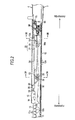
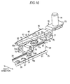
- a lower rail 3 is fixed to a vehicle floor 2 in an aspect of extending in the forward-rearward direction
- an upper rail 4 is mounted on the lower rail 3 to be relatively movable in the forward-rearward direction with respect to the lower rail 3.
- a longitudinal direction of the lower rail 3 and the upper rail 4 that is, a relative movement direction (forward-rearward direction of seat) thereof corresponds to the forward-rearward direction.
- the lower rails 3 and the upper rails 4 are respectively arranged forming a pair in a width direction (direction orthogonal to paper surface in Fig. 1 ), and the drawing illustrates the rails which are disposed on a left side when facing forward (in front of seat). Then, a seat 5 forming a seating portion for a crew is fixed to and supported by both of the upper rails 4.
- the seat 5 is configured to include a seat cushion 7 that forms a seating surface and a seatback 8 that is supported at a rear end portion of the seat cushion 7 to freely inclined about an turning axis O.
- the lower rail 3 and the upper rail 4 are basically in a locking state to be prevented from relatively moving, and there is provided an unlocking handle 6 that releases a locked state.
- the lower rail 3 is formed of a plate material and has a pair of first vertical wall portions 11 and a bottom wall portion 12.
- the pair of first vertical wall portions 11 extend in a vertical direction on both sides in the width direction, and the bottom wall portion 12 connects both of lower ends of these first vertical wall portions 11 to each other.
- a first flange 13 is continuously formed which protrudes inwardly in the width direction, and then, is folded downward to the lower end side of the first vertical wall portion.
- a plurality of notches 13a are formed upward from a tip (lower end) thereof at the predetermined intervals in the same direction and a plurality of square tooth-shaped locking claws 13b are formed between each of the adjacent notches 13a. Therefore, the plurality of locking claws 13b are provided in parallel in the longitudinal direction of the lower rail 3 at the predetermined intervals.
- a connection portion between each first vertical wall portion 11 and the bottom wall portion 12 forms a first lower side ball guide 18 having an approximately arc-shaped cross section to project obliquely outward on a lower side.
- a connection portion between each first flange 13 and the first vertical wall portion 11 forms a first upper side ball guide 13c having the approximately arc-shaped cross section to project obliquely outward on an upper side.
- the upper rail 4 is formed of the plate material and has a pair of second vertical wall portions 14 and a lid wall portion 15.
- the pair of second vertical wall portions 14 extend in the vertical direction between both of the first flanges 13 of the lower rail 3, and a lid wall portion 15 connects both the upper ends of these second vertical wall portions 14 to each other.
- a second flange 16 is continuously formed which protrudes outwardly in the width direction, and then, is folded upward so as to be surrounded by the first vertical wall portion 11 and the first flange 13.
- the lower rail 3 and the upper rail 4 each have an approximately U-shaped cross section in the rail of which open sides confronts with each other and are mainly prevented from being detached in the vertical direction by engagement between the first flange 13 and the second flange 16.
- the cross section of the rails which is formed by the lower rail 3 and the upper rail 4 is in a rectangular shape, a so-called box shape.
- the lower rail 3 forms a space S in association with the upper rail 4.
- each second flange 16 forms a second lower side ball guide 19 having the approximately arc-shaped cross section to project obliquely inward on the upper side. Meanwhile, an upper end portion of each second flange 16 forms a second upper side ball guide 16a having the approximately arc-shaped cross section to project obliquely inward on the lower side.
- a plurality of spherical-shaped balls 20a are interposed between each second lower side ball guide 19 and the first lower side ball guide 18 facing each other, and between each second upper side ball guide 16a and the first upper side ball guide 13c facing each other.
- each ball 20a is mounted on a resin-made holder 20b extending in the forward-rearward direction (longitudinal direction of rail).
- the balls 20a mounted on each of the holders 20b add up to four in total. One pair of them are disposed in a front end portion of the holder 20b and the other pair are disposed in a rear end portion thereof.
- the upper rail 4 is supported to freely slide in the longitudinal direction (forward-rearward direction) with respect to the lower rail 3 so as to roll each of the balls 20a between the lower rail 3 and the upper rail 4.
- concentric circle-shaped axis attachment holes 14b and 14c are respectively formed in front of a vehicle from the open holes 14a communicating with each other in the width direction.
- An inner diameter of the axis attachment hole 14b at one side is set smaller than an inner diameter of the axis attachment hole 14c at the other side.
- a columnar-shaped support axis 22 inserted into the axis attachment holes 14b and 14c at both end portions thereof is supported by both of the second vertical wall portions 14. Needless to mention, a center line of this support axis 22 extends in the width direction.
- the support axis 22 is fastened to the corresponding second vertical wall portion 14 at one end portion which is inserted into the axis attachment hole 14b and connected to be movable in the width direction with respect to the corresponding second vertical wall portion 14 at the other end portion which is inserted into the axis attachment hole 14c. This is done in order to absorb the deformation by moving the support axis 22 in the width direction when the deformation is generated in a cross-sectional shape of the upper rail 4 in accordance with interposition of the above-described ball 20a and the like between the lower rail 3 and the upper rail 4.
- the axis attachment holes 14b and 14c (support axis 22) are disposed in the central portion of the second lower side ball guide 19 and the second upper side ball guide 16a (slide portion for a pair of upper and lower balls 20a) in the vertical direction. This is done in order to suppress the deformation of the axis attachment holes 14b and 14c being minimized when a deformation is generated in the cross-sectional shape of the upper rail 4 in the above-described aspect.
- a locking lever 30 is connected to both of the second vertical wall portions 14 inwardly in the width direction to freely turn by the support axis 22.
- the locking lever 30 includes a handle portion 31 configured of the plate material extending in the forward-rearward direction.
- the handle portion 31 is erected in an aspect in which a pair of vertical wall portions 32 extending in the longitudinal direction thereof are erected in an aspect of being in parallel in the width direction.
- a distance between both of these vertical wall portions 32 in the width direction is set smaller than a distance between both of the second vertical wall portions 14 of the upper rail 4 in the width direction.
- both of the vertical wall portions 32 are connected with each other in the width direction at each front end portion between upper end edges by a connection wall 33, and connected with each other in the width direction at each rear end portion between the upper end edges by a top plate portion 34.
- long holes 35 extending in the forward-rearward direction at a position equivalent to the support axis 22 (axis attachment holes 14b and 14c) in the vertical direction are respectively formed.
- An opening width of these long holes 35 in a short direction (vertical direction) is set equivalent to a diameter of the support axis 22.
- the support axis 22 inserted into each of the axis attachment holes 14b and 14c at respective end portions thereof is inserted through both of the long holes 35 in a state where both of the vertical wall portions 32 of the handle portion 31 are interposed therebetween by both of the second vertical wall portions 14 of the upper rail 4 in the width direction. Accordingly, the handle portion 31 is connected to freely turn with respect to the upper rail 4 in the vertical direction in a state where movement in the forward-rearward direction within a range of the long hole 35 is allowed.
- the locking lever 30 includes a locking plate 39 formed of the plate material and fixed to a lower portion of the rear end portion of the handle portion 31.
- the locking plate 39 spreads in the forward-rearward direction and the width direction in an aspect of penetrating the open hole 14a and the notch 16b in the width direction.
- locking holes 39b which are open in the vertical direction facing each of the first flanges 13 are formed in the locking plate 39.
- the plurality (three) of locking holes 39b are provided in parallel at the predetermined intervals in the forward-rearward direction and disposed at a position capable of corresponding to the plurality (three) of locking claws 13b adjacent to each other in the longitudinal direction of the lower rail 3.
- a size of the locking plate 39 in the width direction is set larger than a distance between both of the second upper side ball guides 16a of the upper rail 4 in the width direction and set smaller than a distance between both of the second flanges 16 in the width direction which are lower than the second upper side ball guides 16a. Therefore, even though the locking plate 39 penetrates the notch 16b in the width direction in a state where the lower rail 3 and the upper rail 4 are locked to be prevented from relatively moving, there is no interference with the second flanges 16 in a state in which the prevented relative movements are unlocked.
- a locking spring 50 formed with one rod of a wire material is disposed inside the upper rail 4.
- the locking spring 50 is formed to have an approximately prone U shape open to the front side in a planar view.
- the locking spring 50 has a wedge portion 53 which is formed by causing an intermediate portion thereof in the longitudinal direction to meanderingly protrude upward, and a lever side locking end portion 54 which is formed by causing a rear end portion thereof to bend upward.
- a front end portion of the locking spring 50 forms a rail side locking end portion 55.
- the locking spring 50 causes the support axis 22 to be inserted between the wedge portion 53 from above the support axis 22, the lever side locking end portion 54 to be inserted through and fixed to the locking plate 39 from below the locking plate 39, and the rail side locking end portion 55 to abut on a lower surface of the lid wall portion 15 of the upper rail 4, thereby being supported by the upper rail 4 and the like.
- the locking spring 50 turns the locking lever 30 to be urged to a side where the locking plate 39 is lifted in the lever side locking end portion 54, that is, a side where the corresponding locking claw 13b fits into each locking hole 39b.
- the locking spring 50 urges the support axis 22 downward, that is, in a direction where the long hole 35 intersects in the longitudinal direction in the wedge portion 53 by a reaction, thereby locking the support axis 22 to be prevented from moving in the forward-rearward direction inside the long hole 35.
- a position of the support axis 22 in the forward-rearward direction inside the long hole 35 is urged and held by the wedge portion 53 of the locking spring 50.
- the unlocking handle 6 is made by bending a cylindrical material and inserted into the upper rail 4 from a front side opening end of the upper rail 4 while a front end portion of the handle portion 31 is inserted therein, thereby being connected to the locking lever 30. Therefore, basically, the unlocking handle 6 integrally turns about the support axis 22 with the locking lever 30. Then, if a front end of the unlocking handle 6 is lifted, the locking lever 30 turns about the support axis 22 along with the unlocking handle 6 to a side where the locking plate 39 is lowered, that is, a side where each locking hole 39b is detached from the corresponding locking claw 13b against the urging force of the locking spring 50.
- an operation force upon the unlocking handle 6 is considered to be released.
- the locking lever 30 turns about the support axis 22 along with the unlocking handle 6 to a side where the locking plate 39 is lifted, that is, a side where each locking hole 39b fits into the corresponding locking claw 13b by the urging force of the locking spring 50, thereby locking the lower rail 3 and the upper rail 4 to be prevented from relatively moving in the above-described aspect. Then, a position of the seat 5 in the forward-rearward direction supported by the upper rail 4 is held.
- the unlocking handle 6 is considered to be in an operation being lifted at the front end thereof.
- the locking lever 30 turns about the support axis 22 along with the unlocking handle 6 to the side where the locking plate 39 is lowered, that is, the side where each locking hole 39b is detached from the corresponding locking claw 13b, thereby unlocking the lower rail 3 and the upper rail 4 prevented from relatively moving in the above-described aspect. Then, it is possible to adjust the position of the seat 5 in the forward-rearward direction supported by the upper rail 4.
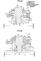
- a plurality of circle-shaped lower side locking holes 12a are formed at the predetermined intervals in the bottom wall portion 12 of the lower rail 3 in the longitudinal direction thereof. Then, an approximately elongated memory guide 25 formed of the plate material having a width smaller than a distance between both of the second vertical wall portions 14 of the upper rail 4 is extended along the plurality of lower side locking holes 12a in the bottom wall portion 12.
- This memory guide 25 has a pair of guide claws 26 which are inwardly folded in the width direction to cause both of the end portions thereof to face each other in the width direction while having an approximately C-shaped cross section, and a plurality of circle-shaped penetration holes 27 are formed respectively facing the plurality of lower side locking holes 12a in a central portion thereof in the width direction. Therefore, the plurality of penetration holes 27 also are provided in parallel in the longitudinal direction of the lower rail 3 at the predetermined intervals. An inner diameter of the penetration hole 27 is set greater than an inner diameter of the lower side locking hole 12a.
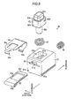
- a memory piece 60 is placed in the memory guide 25. As collectively illustrated in Figs. 8 to 9B , this memory piece 60 is configured to include a memory base 61, a memory pin 62, a locking plate 63 and a detachment prevention plate 64 as well as a first urging member 65 and a second urging member 66 formed with a coil spring, for example.
- the memory base 61 is formed in an approximate block shape having a width equivalent to a width of the memory guide 25 and configured to be movable in the forward-rearward direction (forward-rearward direction of seat) along the memory guide 25 (lower rail 3).
- a pair of guide grooves 61 a which are inwardly concave in the width direction facing each other from both end surfaces thereof in the width direction are formed across the overall length in the forward-rearward direction.
- the memory base 61 moves in the forward-rearward direction along the memory guide 25 while being guided by both of the guide claws 26 by causing both of the guide claws 26 of the memory guide 25 to be locked into both of the guide grooves 61 a to freely slide in the forward-rearward direction.
- an approximately square-shaped guide hole 61 b is formed to be open upward, and a circle-shaped penetration hole 61 c penetrating a bottom wall of the guide hole 61 b is formed having an inner diameter equivalent to the inner diameter of the lower side locking hole 12a.
- the first urging member 65 is accommodated and the memory pin 62 is mounted in an aspect of being inserted through the first urging member 65.
- the memory pin 62 has a main body portion 62a formed in an approximately square prism shape corresponding to an outer shape of the guide hole 61 b and movement thereof in the vertical direction is guided in the main body portion 62a by the guide hole 61 b. In this case, the memory pin 62 is constantly urged to an upward moving side by causing the main body portion 62a to be placed on the first urging member 65.
- the memory pin 62 has an approximately square prism-shaped head portion 62b of which size is smaller than the main body portion 62a in the width direction and the forward-rearward direction while protruding upward.
- the memory pin 62 has an approximately columnar-shaped locking portion 62c which is concentric with the penetration hole 61 c and penetrates the first urging member 65 from the main body portion 62a while protruding downward.
- An outer diameter of the locking portion 62c is set equivalent to the inner diameter of the penetration hole 61 c (lower side locking hole 12a).
- a locked groove 62d in an approximately U groove shape is formed recessed on the front side of the vehicle from an intermediate portion of a rear end surface in the vertical direction across the overall length thereof in the width direction.
- an upper surface of the main body portion 62a forms an approximately square annular-shaped step difference portion 62e at a border position with respect to the head portion 62b.
- a circle-shaped accommodation hole 61 d is formed causing a rear end surface and the guide hole 61 b to communicate with each other in the forward-rearward direction at an intermediate portion thereof in the vertical direction.
- An inner diameter of this accommodation hole 61d is set smaller than an opening width of the guide hole 61 b in the width direction. Then, the second urging member 66 is accommodated in this accommodation hole 61d.
- a plate guide hole 61 e is formed in the memory base 61 to communicate in the forward-rearward direction at a central portion of the accommodation hole 61 d in the vertical direction.
- This plate guide hole 61 e has a slit shape extending in the width direction.
- the opening width of the plate guide hole 61e in the width direction is set greater than the opening width of the guide hole 61 b in the width direction. Therefore, each of inner wall surfaces of the guide hole 61 b and the accommodation holes 61 d is cut off in a groove shape on both outer sides from the plate guide hole 61e in the width direction. Then, the locking plate 63 is inserted and guided into the plate guide hole 61e from in front of the vehicle to freely slide in the forward-rearward direction.
- the locking plate 63 is formed in an approximately square plate shape having a width equivalent to the opening width of the plate guide hole 61 e in the width direction and fits into the plate guide hole 61e from the front of the vehicle.
- the locking plate 63 causes its rear end portion to enter the accommodation hole 61 d and is pressed to be in contact with the second urging member 66, thereby being constantly urged in front of the vehicle.
- An approximately square-shaped open hole 63a is formed in a central portion of the locking plate 63.
- An opening width of this open hole 63a in the width direction is set equivalent to the opening width (width of main body portion 62a) of the guide hole 61 b and the opening width in the forward-rearward direction is set greater than the opening width (length of main body portion 62a in forward-rearward direction) of the guide hole 61 b in the forward-rearward direction.
- the memory pin 62 which is urged upward by the first urging member 65 in the guide hole 61 b basically penetrates the open hole 63a in the main body portion 62a positioned lower than the locked groove 62d. Therefore, the locking plate 63 which is urged by the second urging member 66 is locked to be prevented from moving in front of the vehicle by causing a seat rear side edge portion 63c of the open hole 63a to abut on the main body portion 62a. In this case, the movement of the memory pin 62 in the vertical direction is allowed inside the guide hole 61 b (and the open hole 63a).
- a front end portion of the locking plate 63 is folded rearward from below in an approximate bow shape and forms a pressed portion 63b.
- an approximately square-shaped front side hooking hole 61f is formed which causes the front end surface and the guide hole 61 b to communicate with each other in the forward-rearward direction above the plate guide hole 61 e
- an approximately square-shaped rear side hooking hole 61 g is formed which causes the rear end surface and the guide hole 61 b to communicate with each other in the forward-rearward direction below the accommodation hole 61 d. Then, the detachment prevention plate 64 is fixed to the memory base 61 in the front side hooking hole 61f and the rear side hooking hole 61 g.
- the detachment prevention plate 64 is formed of the plate material and spreads along an upper surface of the memory base 61 while extending a front side hooking claw 64a and a rear side hooking claw 64b individually downward from the front end portion and the rear end portion.
- the detachment prevention plate 64 is in a state of abutting on the upper surface of the memory base 61, and its front side hooking claw 64a and its rear side hooking claw 64b respectively fit into the front side hooking hole 61f and the rear side hooking hole 61 g, thereby being fixed to the memory base 61.
- An approximately square-shaped head portion insertion hole 64c is formed in the central portion of the detachment prevention plate 64.
- An opening width of the head portion insertion hole 64c in the width direction and an opening width thereof in the forward-rearward direction are respectively set equivalent to a width of the head portion 62b and a length thereof in the forward-rearward direction.
- the memory pin 62 urged upward to the first urging member 65 fits into the head portion insertion hole 64c at the head portion 62b. Therefore, the memory pin 62 urged by the first urging member 65 is locked to be prevented from moving upward by causing the step difference portion 62e to abut on a circumferential edge portion of the head portion insertion hole 64c.
- the detachment prevention plate 64 regulates an uppermost position of the memory pin 62 to prevent the memory pin 62 from being detached upward.
- the detachment prevention plate 64 also prevents the second urging member 66 from being detached behind the vehicle by being pressed to be in contact with the rear end of the second urging member 66 which urges the locking plate 63 in front of the vehicle.
- the head portion 62b protrudes upward by a great amount from the detachment prevention plate 64.
- a length of a tip of the locking portion 62c protruding from the penetration hole 61 c is set to be insignificant or nonexistent, and the memory piece 60 is movable in the longitudinal direction of the memory guide 25 (bottom wall portion 12).
- the locking portion 62c protrudes downward by a great amount from the memory base 61. Therefore, in this case, if there is an opening of the lower side locking hole 12a (penetration hole 27) on a lower side of the locking portion 62c, the tip of the locking portion 62c penetrates the penetration hole 27 and the lower side locking hole 12a. In this case, the memory piece 60 is fixed to the lower rail 3 (bottom wall portion 12), thereby being disabled from moving in the longitudinal direction thereof.
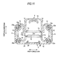
- a stopper member 70 which is formed of a plate material is fixed to and supported by the upper rail 4 at a rearward position of the vehicle with respect to the locking lever 30.
- the stopper member 70 has a support wall portion 71 extending in the forward-rearward direction at a position lower than the memory pin 62 (head portion 62b) that protrudes further upward than the memory base 61 and protrudes in a relatively great length from the memory base 61.
- the stopper member 70 has a pressing piece 72 with a width wider than the support wall portion 71 and extending downward from the front end thereof, and also has an approximately L-shaped attachment piece 73 extending behind the vehicle on the upper side from the rear end of the support wall portion 71.
- the stopper member 70 is fastened to the upper rail 4 by a fastener 78 which penetrates the attachment piece 73 and the lid wall portion 15 in the vertical direction.
- the stopper member 70 has a pair of supported flanges 74 extending in front of the vehicle from both ends of the pressing piece 72 in the width direction.
- Circle-shaped axis penetration holes 74a communicating with each other in the width direction are respectively formed in these supported flanges 74.
- a distance between both of these supported flanges 74 in the width direction is set equivalent to the distance between both of the second vertical wall portions 14 of the upper rail 4 in the width direction.
- concentrically circle-shaped axis attachment holes 14d and 14e communicating with each other in the width direction are respectively formed in both of the second vertical wall portions 14.
- An inner diameter of the axis attachment hole 14d on one side is set smaller than an inner diameter of the axis attachment hole 14e on the other side. Then, a columnar-shaped fixing pin 79 inserted into the axis attachment holes 14d and 14e at both end portions thereof is supported by both of the second vertical wall portions 14. Needless to mention, a center line of this fixing pin 79 extends in the width direction.
- the fixing pin 79 is fastened to the corresponding second vertical wall portion 14 at one end portion which is inserted into the axis attachment hole 14d and connected to be movable in the width direction with respect to the corresponding second vertical wall portion 14 at the other end portion which is inserted into the axis attachment hole 14e. This is done in order to absorb the deformation by moving the fixing pin 79 in the width direction when the deformation is generated in the cross-sectional shape of the upper rail 4 in accordance with interposition of the above-described ball 20a and the like between the lower rail 3 and the upper rail 4.
- the axis attachment holes 14d and 14e (fixing pin 79) are disposed in the central portion of the second lower side ball guide 19 and the second upper side ball guide 16a (slide portion for a pair of upper and lower balls 20a) in the vertical direction. This is done in order to suppress a deformation of the axis attachment holes 14d and 14e being minimized when the deformation is generated in the cross-sectional shape of the upper rail 4 in the above-described aspect.
- the stopper member 70 is reliably fixed to and supported by the upper rail 4 at two points in front and rear by the fastener 78 and the fixing pin 79.
- the stopper member 70 has a pair of stopper pieces 75 extending downward along the pressing piece 72 from both ends of the front end portion of the support wall portion 71 in the width direction. As illustrated in Fig. 4A , these stopper pieces 75 face the memory base 61 further upward than the locking plate 63 behind the vehicle thereof. Meanwhile, the pressing piece 72 faces the locking plate 63 behind vehicle thereof. In other words, when moving behind the vehicle along with the upper rail 4, the stopper member 70 is capable of abutting on the memory base 61 in both of the stopper pieces 75 and capable of abutting on the locking plate 63 (pressed portion 63b) in the pressing piece 72.
- the pressing piece 72 moves the locking plate 63 behind the vehicle against the urging force of the second urging member 66. Accordingly, the memory pin 62 urged upward by the first urging member 65 causes the head portion 62b to protrude upward by a great amount from the detachment prevention plate 64.
- an approximately cross-shaped upper side locking hole 71 a communicating in the vertical direction is formed in the central portion of the support wall portion 71.
- An opening width of this upper side locking hole 71 a in the width direction and an opening width thereof in the forward-rearward direction are each set equivalent to a width of the head portion 62b of the memory pin 62 and a length thereof in the forward-rearward direction.
- the memory pin 62 (memory piece 60) is movable in the forward-rearward direction along the lower rail 3 (memory guide 25) while disabled from moving in the forward-rearward direction with respect to the upper rail 4 to which the stopper member 70 is fixed.
- the memory pin 62 engages with the upper rail 4 in a state of protruding upward from the memory base 61 while unlocking the engagement with respect to the lower rail 3. Then, when the upper rail 4 moves in the forward-rearward direction with respect to the lower rail 3, the memory pin 62 (memory piece 60) integrally moves in the forward-rearward direction as well.
- any one of the plurality of lower side locking holes 12a (penetration holes 27) is set open on the lower side of the locking portion 62c of the memory pin 62.
- the memory piece 60 is fixed to the lower rail 3 (bottom wall portion 12), thereby being disabled from moving in the longitudinal direction thereof.
- the head portion 62b of the memory pin 62 protruding downward from the memory base 61 is set to be positioned further downward than the support wall portion 71. Accordingly, for example, the head portion 62b of the memory pin 62 is detached from the upper side locking hole 71 a, thereby allowing the movement of the upper rail 4 in front of the vehicle, leaving the memory piece 60 remaining.
- the memory pin 62 engages with the lower rail 3 while being disengaged from the upper rail 4 in a state of protruding downward from the memory base 61.
- the stopper member 70 has a pair of attachment flanges 76 extending upward from both ends of the rear end portion of the support wall portion 71 in the width direction. Then, in the stopper member 70, a memory link 80 is connected to freely turn by an attachment pin 77 of which an axis line extends in the width direction, inwardly between both of the attachment flanges 76 in the width direction.
- the memory link 80 is formed of the plate material, has an approximately triangular-shaped top plate portion 81 being tapered toward the front of the vehicle, and has a pair of vertical wall portions 82 extending downward from both ends of the top plate portion 81 in the width direction.
- the memory link 80 is connected to freely turn by the attachment pin 77 penetrating along with both of the attachment flanges 76 in the width direction in the rear end portions of both of the vertical wall portions 82 which are interposed between both of the attachment flanges 76.
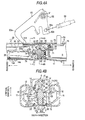
- the upper side of the memory link 80 extends in front of the vehicle along the support wall portion 71 of the stopper member 70, and the front end portion thereof reaches the rear end portion of the locking lever 30 (top plate portion 34) on the upper side. Then, the front end portion of each of the vertical wall portions 82 forms an approximately arc-shaped pressing portion 82a which meanderingly protrudes downward facing the locking lever 30 (top plate portion 34). Therefore, as illustrated in the change from Fig. 4A to Fig.
- an approximately tongue piece-shaped pressing protrusion portion 83 protruding downward and facing the upper side locking hole 71 a is fixedly attached to a central portion of the top plate portion 81 in the forward-rearward direction. Therefore, as illustrated in the drawings in the change from Fig. 4A to Fig. 5A , if the memory link 80 turns about the attachment pin 77 in the counterclockwise direction as illustrated in the drawings, the pressing protrusion portion 83 is inserted into the upper side locking hole 71 a.
- the memory pin 62 is pressed by the pressing protrusion portion 83 so as to protrude downward from the memory base 61 while being locked to be prevented from moving in the vertical direction by the locking plate 63 in the above-described aspect.
- the locking lever 30 pressed by both of the pressing portions 82a is set to reach the turning position in which each locking hole 39b of the locking plate 39 is detached from the corresponding locking claw 13b.
- a memory link urging member 85 formed with a torsional coil spring is wound around the attachment pin 77.
- This memory link urging member 85 is locked to the stopper member 70 (support wall portion 71) at an end and locked to the memory link 80 (top plate portion 81) at the other end, thereby turning the memory link 80 to be urged in a clockwise direction as illustrated in the drawings.
- the memory link 80 is caused to hold an initial turning position where the locking lever30 and the memory piece 60 (memory pin 62) are released due to the urging force by the memory link urging member 85.
- An approximately square-shaped insertion hole 15A which communicates in the vertical direction facing the front end portion of the memory link 80 is formed in the lid wall portion 15 of the upper rail 4. Then, in the upper portion of the upper rail 4 which is in the vicinity of the memory link 80 and the like, a first bell crank link 90 is connected to freely turn around a support axis 91 of which an axis line extends in the width direction as a lever member through an appropriate bracket.
- This first bell crank link 90 is formed of the plate material, has an approximately L-shaped pressing piece 90a with the support axis 91 as the center extending obliquely forward in a radial direction on a lower side, and has an approximately I-shaped attachment piece 90b with the support axis 91 as the center extending in a radial direction on the lower side.
- a tip portion which bends obliquely rearward on the lower side of the pressing piece 90a faces the insertion hole 15A (and front end portion of memory link 80) in the counterclockwise direction about the support axis 91 as illustrated in the drawings, and turning tracks in the turning direction are open through the insertion hole 15A. Therefore, as illustrated in the drawings in the change from Fig. 4A to Fig. 5A , if the first bell crank link 90 turns about the support axis 91 in the counterclockwise direction as illustrated in the drawings, the memory link 80 which is pressed by the tip portion of the pressing piece 90a passing through the insertion hole 15A turns about the attachment pin 77 in the unlocking direction against the urging force of the memory link urging member 85.
- a first lever urging member 92 formed with the torsional coil spring is wound around the support axis 91.
- This first lever urging member 92 is locked to the first bell crank link 90 at one end and locked to the support axis 91 at the other end, thereby turning the first bell crank link 90 to be urged in the clockwise direction as illustrated in the drawings.
- the first bell crank link 90 is caused to hold the initial turning position where the memory link 80 is released due to the urging force by the first lever urging member 92.
- an end 93a of an unlocking cable 93 is locked to the attachment piece 90b.
- This unlocking cable 93 extends behind the vehicle from the attachment piece 90b and is connected to the seatback 8 at the other end thereof.
- the unlocking cable 93 turns the first bell crank link 90 about the support axis 91 in the counterclockwise direction as illustrated in the drawings against the urging force of the first lever urging member 92 by pulling the attachment piece 90b behind the vehicle when the seatback 8 is shifted from a ready-for-seating state to a forward-inclined state (hereinafter, also referred to as "forward tilt").
- forward tilt forward-inclined state
- a state illustrated through Figs. 4A and 4B is as in the following.
- the seatback 8 is not forward-inclined.
- the first bell crank link 90 is held at the initial turning position where the memory link 80 is released due to the urging force by the first lever urging member 92.
- the memory link 80 is held at the initial turning position where the locking lever 30 and the memory piece 60 (memory pin 62) are released due to the urging force by the memory link urging member 85.
- the memory pin 62 protrudes from the memory base 61 due to the urging force of the first urging member 65 and engages with the stopper member 70 (upper rail 4) while being disengaged from the lower rail 3.
- any one of the plurality of lower side locking holes 12a (penetration holes 27) is set to be open on the lower side of the memory pin 62 (locking portion 62c), as described above.
- the memory pin 62 (memory piece 60) is enabled to move along with the upper rail 4 which is released from being locked to be prevented from relatively moving with respect to the lower rail 3 by the locking lever 30. That is, when the upper rail 4 is caused to move in the forward-rearward direction via the operation of the unlocking handle 6, the memory piece 60 integrally moves in the forward-rearward direction as well.
- the memory piece 60 integrally moves with the upper rail 4 in the forward-rearward direction.
- the first bell crank link 90 turns about the support axis 91 in the counterclockwise direction as illustrated in the drawings, and thus, the memory link 80 pressed by the first bell crank link 90 (tip portion of pressing piece 90a) turns in the unlocking direction.
- locking lever 30 which is pressed by both of the pressing portions 82a of the memory link 80 unlocks the upper rail 4 prevented from relatively moving with respect to the lower rail 3.
- the memory pin 62 which is pressed by the pressing protrusion portion 83 of the memory link 80 protrudes downward from the memory base 61, thereby engaging with the lower rail 3 while releasing the engagement with the stopper member 70 (upper rail 4).
- the upper rail 4 is enabled to move in front of the vehicle in a state of the memory pin 62 (memory piece 60) remaining in the lower rail 3.
- the locking lever 30 is continuously pressed by both of the pressing portions 82a of the memory link 8 as long as the seatback 8 is in a forward tilt. Therefore, the state in which the upper rail 4 prevented from relatively moving with respect to the lower rail 3 is unlocked is maintained. In other words, when the seatback 8 is in the forward tilt, the upper rail 4 (seat 5) is allowed to move in front of the vehicle (so-called walk-in operation) until the movement in the direction thereof is regulated by the known stopper mechanism.
- the locking lever 30 is released from both of the pressing portions 82a of the memory link 80 which return to the initial turning position, thereby locking the upper rail 4 to be prevented from relatively moving with respect to the lower rail 3.
- both of the stopper pieces 75 of the stopper member 70 abut on the memory base 61, thereby locking the upper rail 4 to be prevented from moving behind the vehicle.
- both of the stopper pieces 75 (upper rail 4) of the stopper member 70 moving behind the seat are set to abut on the memory base 61. That is, the upper rail 4 stops at a position (stored position) immediately before moving in front of the vehicle in accordance with the forward tilt of the seatback 8.
- the locking plate 63 pressed by the pressing piece 72 of the stopper member 70 moves behind the vehicle, and thus, the memory pin 62 prevented from vertically moving by the locking plate 63 is unlocked.
- the pressing protrusion portion 83 of the memory link 80 approaches over the memory pin 62, thereby locking the memory pin 62 to be prevented from moving upward by the pressing protrusion portion 83.
- the first bell crank link 90 turns about the support axis 91 in the clockwise direction as illustrated in the drawings to return to the initial turning position.
- the memory link 80 which is released from the first bell crank link 90 (tip portion of pressing piece 90a) also returns to the initial turning position.
- the locking lever 30 released from both of the pressing portions 82a of the memory link 80 locks the upper rail 4 to be prevented from relatively moving with respect to the lower rail 3.
- the memory pin 62 released from the pressing protrusion portion 83 of the memory link 80 protrudes from the memory base 61, thereby engaging with the stopper member 70 (upper rail 4) while being disengaged from the lower rail 3.
- the memory guide 25 and the memory piece 60 are not arranged in the lower rail 3 on the opposite side.
- the stopper member 70 and the memory link 80 are not arranged in the upper rail 4 on the opposite side.
- an approximately square-shaped insertion hole 15B is formed communicating in the vertical direction facing the rear end portion of the locking lever 30.
- a second bell crank link 95 as a second lever member is connected through an appropriate bracket to freely turn around a support axis 96 with an axis line extending in the width direction.
- This second bell crank link 95 is formed of the plate material, has an approximately L-shaped pressing piece 95a with the support axis 96 as the center extending obliquely forward in a radial direction on a lower side, and has an approximately I-shaped attachment piece 95b with the support axis 96 as the center extending in a radial direction on the lower side.
- a tip portion which bends obliquely rearward on the lower side of the pressing piece 95a faces the insertion hole 15B (and rear end portion of locking lever 30) in the clockwise direction having the support axis 96 as the center as illustrated in the drawings, and the turning tracks in the turning direction are open through the insertion hole 15B. Therefore, as illustrated in the change from Fig. 12A to Fig. 12B , if the second bell crank link 95 turns about the support axis 96 in the clockwise direction as illustrated in the drawings, the locking lever 30 which is pressed by the tip portion of the pressing piece 95a passing through the insertion hole 15B unlocks the upper rail 4 prevented from relatively moving with respect to the lower rail 3.
- a second lever urging member 97 formed with a torsional coil spring is wound around the support axis 96, for example.
- This second lever urging member 97 is locked to the second bell crank link 95 at an end and locked to support axis 96 at the other end, thereby turning the second bell crank link 95 to be urged in the counterclockwise direction as illustrated in the drawings.
- the second bell crank link 95 is caused to hold an initial turning position where the locking lever 30 is released due to the urging force by the second lever urging member 97.
- an end 98a of an unlocking cable 98 is locked to the attachment piece 95b.
- This unlocking cable 98 extends behind the vehicle from the attachment piece 95b and is connected to the seatback 8 at the other end thereof.
- the unlocking cable 98 turns the second bell crank link 95 about the support axis 96 in the clockwise direction as illustrated in the drawings against the urging force of the second lever urging member 97 by pulling the attachment piece 95b behind the vehicle in accordance with the forward tilt of the seatback 8.
- the locking lever 30 pressed by the tip portion of the pressing piece 95a unlocks the upper rail 4 prevented from relatively moving with respect to the lower rail 3.
- An unlocking moment of the prevented relative movements by the locking lever 30 in accordance with the forward tilt of the seatback 8 is set to be synchronized with the unlocking moment for the prevented relative movements by the locking lever 30 on the side described above.
- the locking lever 30 is released from the second bell crank link 95 which returns to the initial turning position, thereby locking the upper rail 4 to be prevented from relatively moving with respect to the lower rail 3.
- the locking moment of the relative movements by the locking lever 30 is also set to be synchronized with the locking moment of the relative movements by the locking lever 30 on the side described above.
- the memory pin 62 protruding downward from the memory base 61 is locked to be prevented from moving upward, with the locking plate 63 moving in front of the seat by the urging force of the second urging member 66. Therefore, even if the memory pin 62 is released from the downward pressing force due to the memory link 80 (pressing protrusion portion 83) in accordance with the upper rail 4 moving in front of the seat after the forward tilt of the seatback 8, the memory pin 62 maintains a state of protruding downward from the memory base 61, that is, a state of being engaged with the lower rail 3.
- the upper rail 4 which has moved in front of the seat moves behind the seat
- the upper rail 4 abutting on the memory base 61 in the stopper member 70 (both of the stopper pieces 75) in accordance with the restoration to the stored relative position is locked to be prevented from moving behind the seat by the memory pin 62 which engages with the lower rail 3.
- the locking plate 63 moves behind the seat due to the pressing force behind the seat by the stopper member 70 (pressing piece 72) against the urging force of the second urging member 66. Accordingly, the memory pin 62 prevented from moving upward by the locking plate 63 is unlocked.
- the memory pin 62 released from the downward pressing force of the memory link 80 (pressing protrusion portion 83) is urged by the first urging member 65, thereby protruding from the memory base 61. Then, the memory pin 62 engaging with the upper rail 4 is enabled to integrally move with the upper rail 4 along with the memory base 61 and the like.
- the memory piece 60 when the relative position is stored, the memory piece 60 by itself can maintain the engaged state between the memory pin 62 and the lower rail 3.
- the structure is merely an example in which a downward pressing force is applied to the memory pin 62 in accordance with the forward tilt of the seatback 8.
- the memory link 80 may be omitted while a lever for unlocking which presses the locking lever 30 in the turning direction in which the prevented relative movements are unlocked and a lever for a memory operation to apply a downward pressing force to the memory pin 62 are separately provided.
- the structure of the locking lever 30 is merely an example.
- the locking lever may be configured to selectively lock the lower rail 3 and the upper rail 4 to be prevented from relatively moving by detaching from the lower rail 3 in accordance with the turning about the axis line which extends in the forward-rearward direction.
- a step difference portion on which the step difference portion 62e of the memory pin 62 can abut may be formed in the memory base 61 to regulate the uppermost position of the memory pin 62 protruding from the memory base 61.
- the memory pin 62 may be assembled to be placed above upward with respect to the memory base 61.
- the detachment prevention plate 64 may be omitted.
- an appropriate locking claw may be cut and raised from a rear side portion of the locking plate 63, and the locking claw may fit into the locked groove 62d of the memory pin 62, thereby locking the memory pin 62 to be prevented from moving upward.
- a position of the locking plate 63 itself in the vertical direction and a position of the locking claw in the vertical direction to fit into the locked groove 62d may deviate from each other.
- the memory guide 25 may be omitted.
- the memory link 80 may be connected to freely turn around the attachment pin (77) which is directly supported by the upper rail 4.
- an end portion of the attachment pin which is inserted into the second vertical wall portion 14 (axis attachment hole) on a side may be fastened to the second vertical wall portion 14 on the corresponding side, and the other end portion thereof which is inserted into the second vertical wall portion 14 (axis attachment hole) on the other side may be connected to the second vertical wall portion 14 to be movable in the width direction.
- the attachment pin axis attachment hole
- the attachment pin may be disposed in the central portion of the second lower side ball guide 19 and the second upper side ball guide 16a (slide portion of a pair of upper and lower balls 20a) in the vertical direction.
- the attachment pin may be independent of the stopper member 70.
- the attachment pin is connected to the stopper member 70 as well, in the stopper member 70, the attachment pin also is supported by the upper rail 4, and thus, it is possible to improve the strength to support the stopper member 70.
- the upper side locking hole (71 a) may be formed in the upper rail 4 to be directly engaged with the memory pin 62 (head portion 62b) protruding from the memory base 61.
- the upper side locking hole related to the engagement and the like with the memory pin 62 may be independent of the stopper member 70.
- the memory piece 60 is disposed in both of the lower rails 3, and the stopper member 70 and the memory link 80 may be disposed in both of the upper rails 4.
- a mechanism (memory mechanism) related to a restoration operation after the forward tilt of the seatback 8 may be disposed on both sides of the lower rails 3 and the like.
- the axis line of the first bell crank link 90 (support axis 91) is not necessarily present along the width direction.
- the axis line of the second bell crank link 95 is not necessarily present along the width direction.
- the unlocking cables 93 and 98 which are connected to the first and second bell crank links 90 and 95 may be branch cables converging into one line in a connection portion with respect to the seatback 8.
- one of the unlocking cables 93 and 98 which is connected to one of the first and second bell crank links 90 and 95 may be omitted, and the first and second bell crank links 90 and 95 may be connected by a torque rod.
- the unlocking direction of the memory link 80 may be the same turning direction as that of the locking lever 30 unlocking the prevented relative movements.
- both of the end portions of the fixing pin 79 may be collectively and fixedly attached to the both of the second vertical wall portions 14.
- the fixing pin 79 is not necessarily disposed in the central portion between the second lower side ball guide 19 and the second upper side ball guide 16a in the vertical direction.
- the locking lever may be integrally formed with the handle portion and the locking plate in a sheet of the plate material.
- a round hole may be formed in the locking lever 30 (handle portion 31) in place of the long hole 35, and the locking lever 30 may be connected to the upper rail 4 to freely turn by fitting the support axis 22 into the round hole.
- the lower rail 3 may be configured to be bonded with plural sheets of plate material by welding and the like.
- the upper rail 4 may be configured to be bonded with plural sheets of plate material by welding and the like.
- cross-sectional shapes of the lower rail 3 and the upper rail 4 are merely examples.
- the movement of the upper rail 4 (seat 5) in front of the vehicle in accordance with the forward tilt of the seatback 8 may be performed utilizing an urging force of an appropriate urging member or may be manually operated by the crew and the like.
- the lower rail 3 and the upper rail 4 may be configured to be arranged such that there is one of each with respect to the seat 5, or may be configured to be arranged such that there are three or more of each.
- the direction for relative movements of the lower rail and the upper rail may be a width direction of the vehicle.
- a seat slide apparatus for a vehicle includes: a lower rail (3) freely fixed to a vehicle floor (2); an upper rail (4) freely fixed to a seat (5) having a seat cushion (7) forming a seating surface and a seatback (8); and a memory member (60) engaging with the upper rail , wherein the memory member includes: a memory base (61) provided to be movable in a forward-rearward direction of the seat; a memory pin (62) mounted to be movable back and forth in a vertical direction with respect to the memory base; a first urging member (65) urging the memory pin; a locking plate (63) mounted to be movable in the forward-rearward direction of the seat with respect to the memory base; and a second urging member (66) urging the locking plate.
- the memory member includes: a memory base (61) provided to be movable in a forward-rearward direction of the seat; a memory pin (62) mounted to be movable back and forth in a vertical direction with respect to the memory base; a first
Landscapes
- Engineering & Computer Science (AREA)
- Aviation & Aerospace Engineering (AREA)
- Transportation (AREA)
- Mechanical Engineering (AREA)
- Seats For Vehicles (AREA)
Abstract
Description
- This disclosure relates to a seat slide apparatus for a vehicle.
- In the related art,
JP 2011-201434A Fig. 14 , the apparatus includes amemory base 131 that is movable in a forward-rearward direction of a seat along alower rail 110; and amemory pin 133 that is mounted to be movable back and forth in a vertical direction with respect to thememory base 131, engages with anupper rail 120 by protruding upward from thememory base 131 due to an urging force of a memorypiece urging member 132 while being disengaged from thelower rail 110, engages with thelower rail 110 by protruding downward from thememory base 131 due to a downward pressing force applied thereto while being disengaged from theupper rail 120 when a seatback is shifted from a ready-for-seating state to a forward-inclined state (hereinafter, also referred to as "forward tilt"). - The
memory pin 133 is continuously pressed downward by a memory holdingbracket 135 which approaches thereabove when theupper rail 120 moves in front of a seat after the forward tilt of the seatback, thereby maintaining an engagement state and the like with thelower rail 110. - Thereafter, in the forward tilt of the seatback, if the
upper rail 120 moves behind a seat, astopper member 136 which is fixed to a front end portion of theupper rail 120 abuts on thememory base 131, thereby being locked to be prevented from moving. Accordingly, relative positions (stored relative positions) of thelower rail 110 and theupper rail 120 before theupper rail 120 moves in front of the seat in accordance with the forward tilt of the seatback are restored. Subsequently, if the forward tilt is canceled by erecting the seatback, thememory pin 133 which is released from the downward pressing force protrudes from thememory base 131 due to the urging force of the memorypiece urging member 132 and engages with theupper rail 120 while being disengaged from thelower rail 110. - Incidentally, according to
Reference 1, since the engagement state of thememory pin 133 and thelower rail 110 is maintained when theupper rail 120 moves in front of the seat after the forward tilt of the seatback, the memory holdingbracket 135 needs to be able to press thememory pin 133 downward throughout the entire movement range of theupper rail 120 with respect to thelower rail 110. For this reason, thememory holding bracket 135 is configured to extend inside theupper rail 120 along in a longitudinal direction, thereby causing a disposition space necessary for an inside of the rail to be increased. - Thus, a need exists for a seat slide apparatus for a vehicle whose disposition space necessary for the inside of the rail can be further decreased.
- An aspect of this disclosure provides A seat slide apparatus for a vehicle including: a lower rail that is configured to fixed to a vehicle floor; an upper rail that is configured to fixed to a seat which has a seat cushion forming a seating surface and a seatback being supported at a rear end portion of the seat cushion to freely inclined and is connected to be relatively movable with respect to the lower rail in a forward-rearward direction of the seat; and a memory member that engages with the upper rail while being disengaged from the lower rail to be integrally movable with the upper rail when the seatback is in a ready-for-seating state, engages with the lower rail while being disengaged from the upper rail when the seatback is shifted from the ready-for-seating state to a forward-inclined state, and abuts on the upper rail when the upper rail moves behind a seat with respect to the lower rail so as to regulate the upper rail moving behind the seat in a state of engaging with the lower rail while being disengaged from the upper rail, wherein the memory member includes: a memory base which is provided to be movable in the forward-rearward direction of the seat along the lower rail and abuts on the upper rail moving behind the seat when the seatback is shifted from the ready-for-seating state to the forward-inclined state; a memory pin which is mounted to be movable back and forth in a vertical direction with respect to the memory base, is configured to be applied with a downward pressing force when the seatback is shifted from the ready-for-seating state to the forward-inclined state, engages with the upper rail while being disengaged from the lower rail in a state of protruding upward from the memory base, and engages with the lower rail while being disengaged from the upper rail in a state of protruding downward from the memory base; a first urging member which urges the memory pin from the memory base to a side protruding upward; a locking plate which is mounted to be movable in the forward-rearward direction of the seat with respect to the memory base, locks the memory pin to be prevented from moving upward in a state where the memory pin moves in front of the seat while being in a state of protruding downward from the memory base, and moves behind the seat from a front position of the seat while unlocking the memory pin prevented from moving upward by abutting on the upper rail moving behind the seat; and a second urging member which urges the locking plate to a side moving in front of the seat.
- With this configuration, the memory pin protruding downward from the memory base is locked to be prevented from moving upward by moving the locking plate in front of the seat due to an urging force of the second urging member. Therefore, even if the upper rail moves in front of the seat when the seatback is shifted from the ready-for-seating state to the forward-inclined state and the memory pin is released from the downward pressing force, the memory pin maintains a state of protruding downward from the memory base, that is, a state of engaging with the lower rail.
- Thereafter, the upper rail which has moved in front of the seat moves behind the seat, thereby being locked to be prevented from moving by abutting on the memory base which is fixed to the lower rail through the memory pin in the state of engaging with the lower rail. In this case, relative positions of the lower rail and the upper rail are restored to the positions immediately before the upper rail moves in front of the seat while the seatback is shifted from the ready-for-seating state to the forward-inclined state. In addition, in this case, the upper rail abuts on the locking plate, and thus, the locking plate moves behind the seat against the urging force of the second urging member. Accordingly, the memory pin prevented from moving upward by the locking plate is unlocked.
- Therefore, in this state, if the forward-inclined state of the seatback shifted from the ready-for-seating state is canceled, the memory pin released from the downward pressing force is urged by the first urging member, thereby protruding upward from the memory base. Then, the memory pin engaged with the upper rail is integrally movable with the upper rail together with the memory base and the like.
- As above, if the seatback is shifted from the ready-for-seating state to the forward-inclined state, since the memory member itself can maintain the engagement state between the memory pin and the lower rail, it is possible to cause the overall configuration of the apparatus to be simple and compact.
- In the seat slide apparatus for a vehicle, it is preferable that a locked groove is formed in the memory pin, an open hole through which the memory pin is smoothly inserted in the vertical direction is formed in the locking plate, and the locking plate locks the memory pin to be prevented from moving upward by fitting an edge portion of the open hole on a rear side of a seat into the locked groove of the memory pin protruding downward from the memory base in a state of moving in front of the seat due to the urging force of the second urging member.
- With this configuration, it is possible to lock the memory pin to be prevented from moving upward through a significantly simple configuration in which the edge portion of the open hole on the rear side of a seat fits into the locked groove of the memory pin due to the urging force of the second urging member.
- In the seat slide apparatus for a vehicle, it is preferable that the seat slide apparatus further includes a step difference portion that is formed on the memory pin; and a detachment prevention plate that is fixed to the memory base and abuts on the step difference portion to regulate an uppermost position of the memory pin protruding upward from the memory base due to the urging force of the first urging member.
- With this configuration, since the uppermost position of the memory pin protruding upward from the memory base due to the urging force of the first urging member is regulated by abutment of the step difference portion and the detachment prevention plate, it is possible to prevent the memory pin from being detached from the memory base.
- In the seat slide apparatus for a vehicle, it is preferable that the lower rail has a pair of first vertical wall portions which are provided side by side in a width direction, a bottom wall portion which connects both lower ends of the first vertical wall portions to each other, and a pair of first flanges which protrude inwardly from upper ends of both of the first vertical wall portions facing each other in the width direction and are folded downward to the lower end sides of the first vertical wall portions, the upper rail has a pair of second vertical wall portions which are provided side by side in the width direction between both of the first flanges, a lid wall portion which connects both upper ends of the second vertical wall portions to each other, and a pair of second flanges which individually protrude outwardly from lower ends of both of the second vertical wall portions away from each other in the width direction and are folded upward so as to be surrounded by the first vertical wall portions and the first flanges, the memory member is placed on the bottom wall portion, the upper rail is configured to have a stopper member which is fixed to the inside thereof abutting on the memory member when moving behind the seat with respect to the lower rail while the seatback is shifted from the ready-for-seating state to the forward-inclined state, and the seat slide apparatus for a vehicle further includes: a locking member that is connected to the upper rail to freely turn about an axis line extending in the width direction between both of the second vertical wall portions in the width direction and selectively locks the lower rail and the upper rail to be prevented from relatively moving by being detached from the lower rail in accordance with turning in the vertical direction; a memory link that is connected to the upper rail to freely turn about an axis line extending in the width direction between both of the second vertical wall portions in the width direction, holds an initial turning position where the locking member and the memory member are released due to the urging force by a memory link urging member, and presses the locking member in a turning direction of unlocking the prevented relative movements while pressing the memory member downward by turning in an unlocking direction against the urging force of the memory link urging member; and a lever member that is connected to an upper portion of the upper rail to freely turn, holds an initial turning position where the memory link is released due to the urging force by a lever urging member, and presses the memory link in the unlocking direction by turning against the urging force of the lever urging member when the seatback is shifted from the ready-for-seating state to the forward-inclined state.
- With this configuration, if the lever member turns from the initial turning position thereof against the urging force of the lever urging member while the seatback is shifted from the ready-for-seating state to the forward-inclined state, the memory link is pressed in the unlocking direction. Accordingly, if the memory link turns in the unlocking direction from the initial turning position thereof against the urging force of the memory link urging member, the locking member is pressed in the turning direction in which the prevented relative movements are unlocked while pressing the memory member downward. Accordingly, the locking member unlocks the prevented relative movements. At the same time, the memory member engages with the lower rail while being disengaged from the upper rail. In this case, the upper rail is movable in front of the seat. Meanwhile, when the upper rail is on the verge of movement behind the seat, the stopper member abuts on the memory member that is in a state of being fixed with the lower rail, and thus, the upper rail is locked to be prevented from moving. In other words, when the seatback is shifted from the ready-for-seating state to a forward-inclined state, the upper rail is movable only in front of the seat.
- If the upper rail moves behind the seat after moving in front of the seat when the seatback is shifted from the ready-for-seating state to a forward-inclined state, the stopper member abuts on the memory member that is in the state of being fixed with the lower rail, and thus, the upper rail is locked to be prevented from moving. Then, while the seatback is shifted from the ready-for-seating state to a forward-inclined state, relative positions (stored relative positions) of the lower rail and the upper rail before the upper rail moves in front of the seat are restored.
- Thereafter, if the forward-inclined state of the seatback shifted from the ready-for-seating state is canceled, the lever member returns to the initial turning position thereof due to the urging force of the lever urging member, and the memory link returns to the initial turning position thereof due to the urging force of the memory link urging member. Therefore, the locking member released from the memory link locks the relative movements to be prevented. At the same time, the memory member engages with the upper rail while being disengaged from the lower rail due to the urging force of the first urging member.
- Consequently, when the upper rail moves behind the seat after moving in front of the seat while the seatback is shifted from the ready-for-seating state to a forward-inclined state, the state before the movement is restored via cancellation of the forward-inclined state of the seatback shifted from the ready-for-seating state.
- In this case, the locking member, the memory member, the memory link and the stopper member are disposed to be accommodated in a space formed by the lower rail and the upper rail. In addition, through the memory link, it is possible to cause the lever member to press the locking member in the turning direction in which the prevented relative movements are unlocked and to press the memory member downward for engaging and the like with the lower rail. Therefore, basically, only the lever member and the lever urging member are disposed outside (upper portion of upper rail) the lower rail and the upper rail, and thus, it is possible to further decrease a disposition space necessary for an outside of the rail.
- The aspect of this disclosure provides an effect to further decrease a disposition space necessary for an inside of the rail.
- The foregoing and additional features and characteristics of this disclosure will become more apparent from the following detailed description considered with the reference to the accompanying drawings, wherein:
-
Fig. 1 is an exploded perspective view illustrating an embodiment disclosed here; -
Fig. 2 is a longitudinal sectional view illustrating the same embodiment; -
Figs. 3A and 3B are cross-sectional views taken along lines IIIA-IIA and IIIB-IIIB inFig. 2 ; -
Fig. 4A is a longitudinal sectional view illustrating a locked state of relative movements to be prevented, andFig. 4B is a cross-sectional view taken along line IVB-IVB inFig. 4A ; -
Fig. 5A is a longitudinal sectional view illustrating a state in which the prevented relative movements are unlocked in accordance with a forward tilt of a seatback, andFig. 5B is a cross-sectional view taken along line VB-VB inFig. 5A ; -
Fig. 6A is a longitudinal sectional view illustrating a state of being moved forward after the forward tilt of the seatback, andFig. 6B is a cross-sectional view taken along line VIB-VIB inFig. 6A ; -
Fig. 7A is a longitudinal sectional view illustrating a state where a locking plate and a pressing piece are in contact with each other in accordance with a rearward movement after a forward movement, andFig. 7B is a longitudinal sectional view illustrating an abutting state of a memory base and a stopper piece in the same condition; -
Fig. 8 is an exploded perspective view of a memory piece; -
Figs. 9A and 9B are longitudinal sectional views illustrating the memory piece and operations thereof; -
Fig. 10 is a perspective view illustrating a stopper member and surrounding structure thereof; -
Fig. 11 is a cross-sectional view taken along line XI-XI inFig. 4A ; -
Figs. 12A and 12B are longitudinal sectional views illustrating the same embodiment and operations thereof; -
Fig. 13 is a side view illustrating a seat for a vehicle to which this disclosure is applied; and -
Fig. 14 is a longitudinal sectional view illustrating an embodiment in the related art. - Hereinafter, an embodiment of a seat slide apparatus for a vehicle will be described. In the following, a vehicle forward-rearward direction is referred to as a "forward-rearward direction".
- As illustrated in
Fig. 13 , alower rail 3 is fixed to a vehicle floor 2 in an aspect of extending in the forward-rearward direction, and anupper rail 4 is mounted on thelower rail 3 to be relatively movable in the forward-rearward direction with respect to thelower rail 3. In other words, in the embodiment, a longitudinal direction of thelower rail 3 and theupper rail 4, that is, a relative movement direction (forward-rearward direction of seat) thereof corresponds to the forward-rearward direction. - The
lower rails 3 and theupper rails 4 are respectively arranged forming a pair in a width direction (direction orthogonal to paper surface inFig. 1 ), and the drawing illustrates the rails which are disposed on a left side when facing forward (in front of seat). Then, a seat 5 forming a seating portion for a crew is fixed to and supported by both of the upper rails 4. The seat 5 is configured to include a seat cushion 7 that forms a seating surface and a seatback 8 that is supported at a rear end portion of the seat cushion 7 to freely inclined about an turning axis O. Thelower rail 3 and theupper rail 4 are basically in a locking state to be prevented from relatively moving, and there is provided an unlocking handle 6 that releases a locked state. - As illustrated in
Fig. 1 , thelower rail 3 is formed of a plate material and has a pair of firstvertical wall portions 11 and abottom wall portion 12. The pair of firstvertical wall portions 11 extend in a vertical direction on both sides in the width direction, and thebottom wall portion 12 connects both of lower ends of these firstvertical wall portions 11 to each other. Then, in an upper end of each firstvertical wall portion 11, afirst flange 13 is continuously formed which protrudes inwardly in the width direction, and then, is folded downward to the lower end side of the first vertical wall portion. - In addition, as collectively illustrated in
Fig. 2 , in an intermediate portion of eachfirst flange 13 of thelower rail 3 in the longitudinal direction, a plurality ofnotches 13a are formed upward from a tip (lower end) thereof at the predetermined intervals in the same direction and a plurality of square tooth-shapedlocking claws 13b are formed between each of theadjacent notches 13a. Therefore, the plurality of lockingclaws 13b are provided in parallel in the longitudinal direction of thelower rail 3 at the predetermined intervals. - As illustrated in
Fig. 3A , a connection portion between each firstvertical wall portion 11 and thebottom wall portion 12 forms a first lower side ball guide 18 having an approximately arc-shaped cross section to project obliquely outward on a lower side. Meanwhile, a connection portion between eachfirst flange 13 and the firstvertical wall portion 11 forms a first upperside ball guide 13c having the approximately arc-shaped cross section to project obliquely outward on an upper side. - The
upper rail 4 is formed of the plate material and has a pair of secondvertical wall portions 14 and alid wall portion 15. The pair of secondvertical wall portions 14 extend in the vertical direction between both of thefirst flanges 13 of thelower rail 3, and alid wall portion 15 connects both the upper ends of these secondvertical wall portions 14 to each other. Then, in a lower end of each secondvertical wall portion 14, asecond flange 16 is continuously formed which protrudes outwardly in the width direction, and then, is folded upward so as to be surrounded by the firstvertical wall portion 11 and thefirst flange 13. - In other words, the
lower rail 3 and theupper rail 4 each have an approximately U-shaped cross section in the rail of which open sides confronts with each other and are mainly prevented from being detached in the vertical direction by engagement between thefirst flange 13 and thesecond flange 16. The cross section of the rails which is formed by thelower rail 3 and theupper rail 4 is in a rectangular shape, a so-called box shape. Thelower rail 3 forms a space S in association with theupper rail 4. - A lower end portion of each
second flange 16 forms a second lower side ball guide 19 having the approximately arc-shaped cross section to project obliquely inward on the upper side. Meanwhile, an upper end portion of eachsecond flange 16 forms a second upper side ball guide 16a having the approximately arc-shaped cross section to project obliquely inward on the lower side. - A plurality of spherical-shaped
balls 20a are interposed between each second lower side ball guide 19 and the first lower side ball guide 18 facing each other, and between each second upper side ball guide 16a and the first upperside ball guide 13c facing each other. - As illustrated in
Fig. 1 , eachball 20a is mounted on a resin-madeholder 20b extending in the forward-rearward direction (longitudinal direction of rail). Theballs 20a mounted on each of theholders 20b add up to four in total. One pair of them are disposed in a front end portion of theholder 20b and the other pair are disposed in a rear end portion thereof. Theupper rail 4 is supported to freely slide in the longitudinal direction (forward-rearward direction) with respect to thelower rail 3 so as to roll each of theballs 20a between thelower rail 3 and theupper rail 4. - In both of the second
vertical wall portions 14 of theupper rail 4, approximately square-shapedopen holes 14a communicating in the width direction on a central portion thereof in the longitudinal direction are respectively formed. In addition, in an upper end portion (second upperside ball guide 16a) of each of thesecond flanges 16 of theupper rail 4, approximately square-shapednotches 16b are respectively formed matching positions of theopen holes 14a in the longitudinal direction thereof. Each of thenotches 16b is open upward to communicate in the width direction. - In addition, as illustrated in
Fig. 3A , in both of the secondvertical wall portions 14, concentric circle-shaped axis attachment holes 14b and 14c are respectively formed in front of a vehicle from theopen holes 14a communicating with each other in the width direction. An inner diameter of theaxis attachment hole 14b at one side is set smaller than an inner diameter of theaxis attachment hole 14c at the other side. Then, a columnar-shapedsupport axis 22 inserted into the axis attachment holes 14b and 14c at both end portions thereof is supported by both of the secondvertical wall portions 14. Needless to mention, a center line of thissupport axis 22 extends in the width direction. - The
support axis 22 is fastened to the corresponding secondvertical wall portion 14 at one end portion which is inserted into theaxis attachment hole 14b and connected to be movable in the width direction with respect to the corresponding secondvertical wall portion 14 at the other end portion which is inserted into theaxis attachment hole 14c. This is done in order to absorb the deformation by moving thesupport axis 22 in the width direction when the deformation is generated in a cross-sectional shape of theupper rail 4 in accordance with interposition of the above-describedball 20a and the like between thelower rail 3 and theupper rail 4. In addition, the axis attachment holes 14b and 14c (support axis 22) are disposed in the central portion of the second lower side ball guide 19 and the second upperside ball guide 16a (slide portion for a pair of upper andlower balls 20a) in the vertical direction. This is done in order to suppress the deformation of the axis attachment holes 14b and 14c being minimized when a deformation is generated in the cross-sectional shape of theupper rail 4 in the above-described aspect. - As illustrated in
Fig. 1 , inside theupper rail 4, a lockinglever 30 is connected to both of the secondvertical wall portions 14 inwardly in the width direction to freely turn by thesupport axis 22. In other words, the lockinglever 30 includes ahandle portion 31 configured of the plate material extending in the forward-rearward direction. Thehandle portion 31 is erected in an aspect in which a pair ofvertical wall portions 32 extending in the longitudinal direction thereof are erected in an aspect of being in parallel in the width direction. A distance between both of thesevertical wall portions 32 in the width direction is set smaller than a distance between both of the secondvertical wall portions 14 of theupper rail 4 in the width direction. Then, both of thevertical wall portions 32 are connected with each other in the width direction at each front end portion between upper end edges by aconnection wall 33, and connected with each other in the width direction at each rear end portion between the upper end edges by atop plate portion 34. - In both of the
vertical wall portions 32,long holes 35 extending in the forward-rearward direction at a position equivalent to the support axis 22 (axis attachment holes 14b and 14c) in the vertical direction are respectively formed. An opening width of theselong holes 35 in a short direction (vertical direction) is set equivalent to a diameter of thesupport axis 22. Thesupport axis 22 inserted into each of the axis attachment holes 14b and 14c at respective end portions thereof is inserted through both of thelong holes 35 in a state where both of thevertical wall portions 32 of thehandle portion 31 are interposed therebetween by both of the secondvertical wall portions 14 of theupper rail 4 in the width direction. Accordingly, thehandle portion 31 is connected to freely turn with respect to theupper rail 4 in the vertical direction in a state where movement in the forward-rearward direction within a range of thelong hole 35 is allowed. - In addition, the locking
lever 30 includes a lockingplate 39 formed of the plate material and fixed to a lower portion of the rear end portion of thehandle portion 31. As collectively illustrated inFig. 3B , the lockingplate 39 spreads in the forward-rearward direction and the width direction in an aspect of penetrating theopen hole 14a and thenotch 16b in the width direction. Then, lockingholes 39b which are open in the vertical direction facing each of thefirst flanges 13 are formed in the lockingplate 39. The plurality (three) of lockingholes 39b are provided in parallel at the predetermined intervals in the forward-rearward direction and disposed at a position capable of corresponding to the plurality (three) of lockingclaws 13b adjacent to each other in the longitudinal direction of thelower rail 3. - Then, as illustrated in a solid line in
Fig. 3B , when the lockinglever 30 turns about thesupport axis 22 so as to cause the lockingplate 39 to be lifted, the corresponding lockingclaws 13b can fit into each of the lockingholes 39b. When the corresponding lockingclaws 13b are inserted into each of the lockingholes 39b, thelower rail 3 and theupper rail 4 are locked to be prevented from relatively moving. Meanwhile, as illustrated in a double-dotted chain line inFig. 3B , when the lockinglever 30 turns about thesupport axis 22 so as to cause the lockingplate 39 to be lowered, each of the lockingholes 39b is set to be detached from the corresponding lockingclaws 13b. In this case, thelower rail 3 and theupper rail 4 prevented from relatively moving are unlocked. - A size of the locking
plate 39 in the width direction is set larger than a distance between both of the second upper side ball guides 16a of theupper rail 4 in the width direction and set smaller than a distance between both of thesecond flanges 16 in the width direction which are lower than the second upper side ball guides 16a. Therefore, even though the lockingplate 39 penetrates thenotch 16b in the width direction in a state where thelower rail 3 and theupper rail 4 are locked to be prevented from relatively moving, there is no interference with thesecond flanges 16 in a state in which the prevented relative movements are unlocked. - As illustrated in
Fig. 1 , a lockingspring 50 formed with one rod of a wire material is disposed inside theupper rail 4. The lockingspring 50 is formed to have an approximately prone U shape open to the front side in a planar view. Then, the lockingspring 50 has awedge portion 53 which is formed by causing an intermediate portion thereof in the longitudinal direction to meanderingly protrude upward, and a lever side locking end portion 54 which is formed by causing a rear end portion thereof to bend upward. In addition, a front end portion of the lockingspring 50 forms a rail side lockingend portion 55. As collectively illustrated inFig. 2 , the lockingspring 50 causes thesupport axis 22 to be inserted between thewedge portion 53 from above thesupport axis 22, the lever side locking end portion 54 to be inserted through and fixed to the lockingplate 39 from below the lockingplate 39, and the rail side lockingend portion 55 to abut on a lower surface of thelid wall portion 15 of theupper rail 4, thereby being supported by theupper rail 4 and the like. - In this case, the locking
spring 50 turns the lockinglever 30 to be urged to a side where the lockingplate 39 is lifted in the lever side locking end portion 54, that is, a side where the corresponding lockingclaw 13b fits into each lockinghole 39b. In addition, the lockingspring 50 urges thesupport axis 22 downward, that is, in a direction where thelong hole 35 intersects in the longitudinal direction in thewedge portion 53 by a reaction, thereby locking thesupport axis 22 to be prevented from moving in the forward-rearward direction inside thelong hole 35. In other words, a position of thesupport axis 22 in the forward-rearward direction inside thelong hole 35 is urged and held by thewedge portion 53 of the lockingspring 50. - The unlocking handle 6 is made by bending a cylindrical material and inserted into the
upper rail 4 from a front side opening end of theupper rail 4 while a front end portion of thehandle portion 31 is inserted therein, thereby being connected to the lockinglever 30. Therefore, basically, the unlocking handle 6 integrally turns about thesupport axis 22 with the lockinglever 30. Then, if a front end of the unlocking handle 6 is lifted, the lockinglever 30 turns about thesupport axis 22 along with the unlocking handle 6 to a side where the lockingplate 39 is lowered, that is, a side where each lockinghole 39b is detached from the corresponding lockingclaw 13b against the urging force of the lockingspring 50. - Here, an operation force upon the unlocking handle 6 is considered to be released. In this case, the locking
lever 30 turns about thesupport axis 22 along with the unlocking handle 6 to a side where the lockingplate 39 is lifted, that is, a side where each lockinghole 39b fits into the corresponding lockingclaw 13b by the urging force of the lockingspring 50, thereby locking thelower rail 3 and theupper rail 4 to be prevented from relatively moving in the above-described aspect. Then, a position of the seat 5 in the forward-rearward direction supported by theupper rail 4 is held. - Thereafter, the unlocking handle 6 is considered to be in an operation being lifted at the front end thereof. In this case, against the urging force of the locking
spring 50, the lockinglever 30 turns about thesupport axis 22 along with the unlocking handle 6 to the side where the lockingplate 39 is lowered, that is, the side where each lockinghole 39b is detached from the corresponding lockingclaw 13b, thereby unlocking thelower rail 3 and theupper rail 4 prevented from relatively moving in the above-described aspect. Then, it is possible to adjust the position of the seat 5 in the forward-rearward direction supported by theupper rail 4. - Next, surrounding structure of the
lower rail 3 and the like on one side between thelower rails 3 and the like forming a pair will be described. - As illustrated in
Figs. 4A and 4B , a plurality of circle-shaped lowerside locking holes 12a are formed at the predetermined intervals in thebottom wall portion 12 of thelower rail 3 in the longitudinal direction thereof. Then, an approximatelyelongated memory guide 25 formed of the plate material having a width smaller than a distance between both of the secondvertical wall portions 14 of theupper rail 4 is extended along the plurality of lowerside locking holes 12a in thebottom wall portion 12. Thismemory guide 25 has a pair ofguide claws 26 which are inwardly folded in the width direction to cause both of the end portions thereof to face each other in the width direction while having an approximately C-shaped cross section, and a plurality of circle-shaped penetration holes 27 are formed respectively facing the plurality of lowerside locking holes 12a in a central portion thereof in the width direction. Therefore, the plurality of penetration holes 27 also are provided in parallel in the longitudinal direction of thelower rail 3 at the predetermined intervals. An inner diameter of thepenetration hole 27 is set greater than an inner diameter of the lowerside locking hole 12a. - A
memory piece 60 is placed in thememory guide 25. As collectively illustrated inFigs. 8 to 9B , thismemory piece 60 is configured to include amemory base 61, amemory pin 62, a lockingplate 63 and adetachment prevention plate 64 as well as a first urgingmember 65 and a second urgingmember 66 formed with a coil spring, for example. - The
memory base 61 is formed in an approximate block shape having a width equivalent to a width of thememory guide 25 and configured to be movable in the forward-rearward direction (forward-rearward direction of seat) along the memory guide 25 (lower rail 3). In other words, in thememory base 61, a pair ofguide grooves 61 a which are inwardly concave in the width direction facing each other from both end surfaces thereof in the width direction are formed across the overall length in the forward-rearward direction. Thememory base 61 moves in the forward-rearward direction along thememory guide 25 while being guided by both of theguide claws 26 by causing both of theguide claws 26 of thememory guide 25 to be locked into both of theguide grooves 61 a to freely slide in the forward-rearward direction. - In addition, in the
memory base 61, an approximately square-shapedguide hole 61 b is formed to be open upward, and a circle-shapedpenetration hole 61 c penetrating a bottom wall of theguide hole 61 b is formed having an inner diameter equivalent to the inner diameter of the lowerside locking hole 12a. Then, in theguide hole 61 b of thememory base 61, the first urgingmember 65 is accommodated and thememory pin 62 is mounted in an aspect of being inserted through the first urgingmember 65. Thememory pin 62 has amain body portion 62a formed in an approximately square prism shape corresponding to an outer shape of theguide hole 61 b and movement thereof in the vertical direction is guided in themain body portion 62a by theguide hole 61 b. In this case, thememory pin 62 is constantly urged to an upward moving side by causing themain body portion 62a to be placed on the first urgingmember 65. - The
memory pin 62 has an approximately square prism-shapedhead portion 62b of which size is smaller than themain body portion 62a in the width direction and the forward-rearward direction while protruding upward. Thememory pin 62 has an approximately columnar-shapedlocking portion 62c which is concentric with thepenetration hole 61 c and penetrates the first urgingmember 65 from themain body portion 62a while protruding downward. An outer diameter of the lockingportion 62c is set equivalent to the inner diameter of thepenetration hole 61 c (lowerside locking hole 12a). - A locked
groove 62d in an approximately U groove shape is formed recessed on the front side of the vehicle from an intermediate portion of a rear end surface in the vertical direction across the overall length thereof in the width direction. In addition, an upper surface of themain body portion 62a forms an approximately square annular-shapedstep difference portion 62e at a border position with respect to thehead portion 62b. - Moreover, in the
memory base 61, a circle-shapedaccommodation hole 61 d is formed causing a rear end surface and theguide hole 61 b to communicate with each other in the forward-rearward direction at an intermediate portion thereof in the vertical direction. An inner diameter of thisaccommodation hole 61d is set smaller than an opening width of theguide hole 61 b in the width direction. Then, the second urgingmember 66 is accommodated in thisaccommodation hole 61d. - In addition, a
plate guide hole 61 e is formed in thememory base 61 to communicate in the forward-rearward direction at a central portion of theaccommodation hole 61 d in the vertical direction. Thisplate guide hole 61 e has a slit shape extending in the width direction. The opening width of theplate guide hole 61e in the width direction is set greater than the opening width of theguide hole 61 b in the width direction. Therefore, each of inner wall surfaces of theguide hole 61 b and the accommodation holes 61 d is cut off in a groove shape on both outer sides from theplate guide hole 61e in the width direction. Then, the lockingplate 63 is inserted and guided into theplate guide hole 61e from in front of the vehicle to freely slide in the forward-rearward direction. In other words, the lockingplate 63 is formed in an approximately square plate shape having a width equivalent to the opening width of theplate guide hole 61 e in the width direction and fits into theplate guide hole 61e from the front of the vehicle. In this case, as illustrated inFigs. 9A and 9B , the lockingplate 63 causes its rear end portion to enter theaccommodation hole 61 d and is pressed to be in contact with the second urgingmember 66, thereby being constantly urged in front of the vehicle. - An approximately square-shaped
open hole 63a is formed in a central portion of the lockingplate 63. An opening width of thisopen hole 63a in the width direction is set equivalent to the opening width (width ofmain body portion 62a) of theguide hole 61 b and the opening width in the forward-rearward direction is set greater than the opening width (length ofmain body portion 62a in forward-rearward direction) of theguide hole 61 b in the forward-rearward direction. - As illustrated in
Fig. 9A , thememory pin 62 which is urged upward by the first urgingmember 65 in theguide hole 61 b basically penetrates theopen hole 63a in themain body portion 62a positioned lower than the lockedgroove 62d. Therefore, the lockingplate 63 which is urged by the second urgingmember 66 is locked to be prevented from moving in front of the vehicle by causing a seat rearside edge portion 63c of theopen hole 63a to abut on themain body portion 62a. In this case, the movement of thememory pin 62 in the vertical direction is allowed inside theguide hole 61 b (and theopen hole 63a). - Meanwhile, as illustrated in
Fig. 9B , if thememory pin 62 moves downward against the urging force of the first urgingmember 65 inside theguide hole 61 b, and the lockedgroove 62d reaches a position of the lockingplate 63 in the vertical direction, the seat rearside edge portion 63c of theopen hole 63a which moves in front of the vehicle by the urging force of the second urgingmember 66 fits into the lockedgroove 62d. In this case, the movement of thememory pin 62 inside theguide hole 61 b (and theopen hole 63a) in the vertical direction is regulated. - A front end portion of the locking
plate 63 is folded rearward from below in an approximate bow shape and forms a pressedportion 63b. - Moreover, in the
memory base 61, an approximately square-shaped frontside hooking hole 61f is formed which causes the front end surface and theguide hole 61 b to communicate with each other in the forward-rearward direction above theplate guide hole 61 e, and an approximately square-shaped rearside hooking hole 61 g is formed which causes the rear end surface and theguide hole 61 b to communicate with each other in the forward-rearward direction below theaccommodation hole 61 d. Then, thedetachment prevention plate 64 is fixed to thememory base 61 in the frontside hooking hole 61f and the rearside hooking hole 61 g. In other words, thedetachment prevention plate 64 is formed of the plate material and spreads along an upper surface of thememory base 61 while extending a frontside hooking claw 64a and a rearside hooking claw 64b individually downward from the front end portion and the rear end portion. Thedetachment prevention plate 64 is in a state of abutting on the upper surface of thememory base 61, and its frontside hooking claw 64a and its rearside hooking claw 64b respectively fit into the frontside hooking hole 61f and the rearside hooking hole 61 g, thereby being fixed to thememory base 61. - An approximately square-shaped head
portion insertion hole 64c is formed in the central portion of thedetachment prevention plate 64. An opening width of the headportion insertion hole 64c in the width direction and an opening width thereof in the forward-rearward direction are respectively set equivalent to a width of thehead portion 62b and a length thereof in the forward-rearward direction. Then, as illustrated inFig. 9A , thememory pin 62 urged upward to the first urgingmember 65 fits into the headportion insertion hole 64c at thehead portion 62b. Therefore, thememory pin 62 urged by the first urgingmember 65 is locked to be prevented from moving upward by causing thestep difference portion 62e to abut on a circumferential edge portion of the headportion insertion hole 64c. In other words, thedetachment prevention plate 64 regulates an uppermost position of thememory pin 62 to prevent thememory pin 62 from being detached upward. Thedetachment prevention plate 64 also prevents the second urgingmember 66 from being detached behind the vehicle by being pressed to be in contact with the rear end of the second urgingmember 66 which urges the lockingplate 63 in front of the vehicle. - Here, as illustrated in
Fig. 9A , in a state where thememory pin 62 moves upward to cause thestep difference portion 62e to abut on the circumferential edge portion of the headportion insertion hole 64c (state wherememory pin 62 is locked to be prevented from moving upward bystep difference portion 62e), thehead portion 62b protrudes upward by a great amount from thedetachment prevention plate 64. In this case, a length of a tip of the lockingportion 62c protruding from thepenetration hole 61 c is set to be insignificant or nonexistent, and thememory piece 60 is movable in the longitudinal direction of the memory guide 25 (bottom wall portion 12). - Meanwhile, as illustrated in
Fig. 9B , in a state where the seat rearside edge portion 63c of theopen hole 63a of the lockingplate 63 fits into the lockedgroove 62d of thememory pin 62 moved downward and thememory pin 62 is locked to be prevented from moving in the vertical direction, the lockingportion 62c protrudes downward by a great amount from thememory base 61. Therefore, in this case, if there is an opening of the lowerside locking hole 12a (penetration hole 27) on a lower side of the lockingportion 62c, the tip of the lockingportion 62c penetrates thepenetration hole 27 and the lowerside locking hole 12a. In this case, thememory piece 60 is fixed to the lower rail 3 (bottom wall portion 12), thereby being disabled from moving in the longitudinal direction thereof. - As illustrated in
Fig. 4A , astopper member 70 which is formed of a plate material is fixed to and supported by theupper rail 4 at a rearward position of the vehicle with respect to the lockinglever 30. In other words, thestopper member 70 has asupport wall portion 71 extending in the forward-rearward direction at a position lower than the memory pin 62 (head portion 62b) that protrudes further upward than thememory base 61 and protrudes in a relatively great length from thememory base 61. Thestopper member 70 has apressing piece 72 with a width wider than thesupport wall portion 71 and extending downward from the front end thereof, and also has an approximately L-shapedattachment piece 73 extending behind the vehicle on the upper side from the rear end of thesupport wall portion 71. Thestopper member 70 is fastened to theupper rail 4 by afastener 78 which penetrates theattachment piece 73 and thelid wall portion 15 in the vertical direction. - In addition, as collectively illustrated in
Fig. 10 , thestopper member 70 has a pair of supportedflanges 74 extending in front of the vehicle from both ends of thepressing piece 72 in the width direction. Circle-shaped axis penetration holes 74a communicating with each other in the width direction are respectively formed in these supportedflanges 74. As illustrated inFig. 11 , a distance between both of these supportedflanges 74 in the width direction is set equivalent to the distance between both of the secondvertical wall portions 14 of theupper rail 4 in the width direction. Then, concentrically circle-shaped axis attachment holes 14d and 14e communicating with each other in the width direction are respectively formed in both of the secondvertical wall portions 14. An inner diameter of theaxis attachment hole 14d on one side is set smaller than an inner diameter of theaxis attachment hole 14e on the other side. Then, a columnar-shapedfixing pin 79 inserted into the axis attachment holes 14d and 14e at both end portions thereof is supported by both of the secondvertical wall portions 14. Needless to mention, a center line of this fixingpin 79 extends in the width direction. - The fixing
pin 79 is fastened to the corresponding secondvertical wall portion 14 at one end portion which is inserted into theaxis attachment hole 14d and connected to be movable in the width direction with respect to the corresponding secondvertical wall portion 14 at the other end portion which is inserted into theaxis attachment hole 14e. This is done in order to absorb the deformation by moving the fixingpin 79 in the width direction when the deformation is generated in the cross-sectional shape of theupper rail 4 in accordance with interposition of the above-describedball 20a and the like between thelower rail 3 and theupper rail 4. In addition, the axis attachment holes 14d and 14e (fixing pin 79) are disposed in the central portion of the second lower side ball guide 19 and the second upperside ball guide 16a (slide portion for a pair of upper andlower balls 20a) in the vertical direction. This is done in order to suppress a deformation of the axis attachment holes 14d and 14e being minimized when the deformation is generated in the cross-sectional shape of theupper rail 4 in the above-described aspect. - As above, the
stopper member 70 is reliably fixed to and supported by theupper rail 4 at two points in front and rear by thefastener 78 and the fixingpin 79. - As illustrated in
Fig. 10 , thestopper member 70 has a pair ofstopper pieces 75 extending downward along thepressing piece 72 from both ends of the front end portion of thesupport wall portion 71 in the width direction. As illustrated inFig. 4A , thesestopper pieces 75 face thememory base 61 further upward than the lockingplate 63 behind the vehicle thereof. Meanwhile, thepressing piece 72 faces the lockingplate 63 behind vehicle thereof. In other words, when moving behind the vehicle along with theupper rail 4, thestopper member 70 is capable of abutting on thememory base 61 in both of thestopper pieces 75 and capable of abutting on the locking plate 63 (pressedportion 63b) in thepressing piece 72. Particularly, in a state where both of thestopper pieces 75 abut on thememory base 61, thepressing piece 72 moves the lockingplate 63 behind the vehicle against the urging force of the second urgingmember 66. Accordingly, thememory pin 62 urged upward by the first urgingmember 65 causes thehead portion 62b to protrude upward by a great amount from thedetachment prevention plate 64. - As collectively illustrated in
Fig. 10 , an approximately cross-shaped upperside locking hole 71 a communicating in the vertical direction is formed in the central portion of thesupport wall portion 71. An opening width of this upperside locking hole 71 a in the width direction and an opening width thereof in the forward-rearward direction are each set equivalent to a width of thehead portion 62b of thememory pin 62 and a length thereof in the forward-rearward direction. Then, in a state where thestopper member 70 abuts on thememory base 61 in both of thestopper pieces 75, thememory pin 62 urged upward by the first urgingmember 65 fits into the upperside locking hole 71 a at thehead portion 62b thereof. - Therefore, the memory pin 62 (memory piece 60) is movable in the forward-rearward direction along the lower rail 3 (memory guide 25) while disabled from moving in the forward-rearward direction with respect to the
upper rail 4 to which thestopper member 70 is fixed. In other words, thememory pin 62 engages with theupper rail 4 in a state of protruding upward from thememory base 61 while unlocking the engagement with respect to thelower rail 3. Then, when theupper rail 4 moves in the forward-rearward direction with respect to thelower rail 3, the memory pin 62 (memory piece 60) integrally moves in the forward-rearward direction as well. Otherwise, when movement of theupper rail 4 in the forward-rearward direction with respect to thelower rail 3 is regulated by the lockinglever 30, movement of the memory pin 62 (memory piece 60) in the forward-rearward direction is also regulated. In this case, any one of the plurality of lowerside locking holes 12a (penetration holes 27) is set open on the lower side of the lockingportion 62c of thememory pin 62. - As described above, when the locking
portion 62c of thememory pin 62 protrudes downward by a great amount form thememory base 61 so that the tip thereof penetrates the penetration holes 61 c and 27 and the lowerside locking hole 12a, thememory piece 60 is fixed to the lower rail 3 (bottom wall portion 12), thereby being disabled from moving in the longitudinal direction thereof. In this case, thehead portion 62b of thememory pin 62 protruding downward from thememory base 61 is set to be positioned further downward than thesupport wall portion 71. Accordingly, for example, thehead portion 62b of thememory pin 62 is detached from the upperside locking hole 71 a, thereby allowing the movement of theupper rail 4 in front of the vehicle, leaving thememory piece 60 remaining. In other words, thememory pin 62 engages with thelower rail 3 while being disengaged from theupper rail 4 in a state of protruding downward from thememory base 61. - As illustrated in
Fig. 10 , thestopper member 70 has a pair ofattachment flanges 76 extending upward from both ends of the rear end portion of thesupport wall portion 71 in the width direction. Then, in thestopper member 70, amemory link 80 is connected to freely turn by anattachment pin 77 of which an axis line extends in the width direction, inwardly between both of theattachment flanges 76 in the width direction. In other words, thememory link 80 is formed of the plate material, has an approximately triangular-shapedtop plate portion 81 being tapered toward the front of the vehicle, and has a pair ofvertical wall portions 82 extending downward from both ends of thetop plate portion 81 in the width direction. Then, thememory link 80 is connected to freely turn by theattachment pin 77 penetrating along with both of theattachment flanges 76 in the width direction in the rear end portions of both of thevertical wall portions 82 which are interposed between both of theattachment flanges 76. - As illustrated in
Fig. 4A , the upper side of thememory link 80 extends in front of the vehicle along thesupport wall portion 71 of thestopper member 70, and the front end portion thereof reaches the rear end portion of the locking lever 30 (top plate portion 34) on the upper side. Then, the front end portion of each of thevertical wall portions 82 forms an approximately arc-shapedpressing portion 82a which meanderingly protrudes downward facing the locking lever 30 (top plate portion 34). Therefore, as illustrated in the change fromFig. 4A to Fig. 5A , if thememory link 80 turns about theattachment pin 77 in a counterclockwise direction (hereinafter, also referred to as "unlocking direction") as illustrated in the drawings, the lockinglever 30 pressed by both of thepressing portions 82a is caused to turn about thesupport axis 22 against the urging force of the lockingspring 50 to a side to which thelocking plate 39 is lowered, that is, a side where each of the lockingholes 39b is detached from the corresponding lockingclaws 13b. - In addition, an approximately tongue piece-shaped
pressing protrusion portion 83 protruding downward and facing the upperside locking hole 71 a is fixedly attached to a central portion of thetop plate portion 81 in the forward-rearward direction. Therefore, as illustrated in the drawings in the change fromFig. 4A to Fig. 5A , if thememory link 80 turns about theattachment pin 77 in the counterclockwise direction as illustrated in the drawings, thepressing protrusion portion 83 is inserted into the upperside locking hole 71 a. In this case, if thehead portion 62b of thememory pin 62 fits into the upperside locking hole 71 a, thememory pin 62 is pressed by thepressing protrusion portion 83 so as to protrude downward from thememory base 61 while being locked to be prevented from moving in the vertical direction by the lockingplate 63 in the above-described aspect. At a turning position of thememory link 80 when thememory pin 62 pressed by thepressing protrusion portion 83 is locked to be prevented from moving in the vertical direction by the lockingplate 63, the lockinglever 30 pressed by both of thepressing portions 82a is set to reach the turning position in which eachlocking hole 39b of the lockingplate 39 is detached from the corresponding lockingclaw 13b. - For example, a memory
link urging member 85 formed with a torsional coil spring is wound around theattachment pin 77. This memorylink urging member 85 is locked to the stopper member 70 (support wall portion 71) at an end and locked to the memory link 80 (top plate portion 81) at the other end, thereby turning thememory link 80 to be urged in a clockwise direction as illustrated in the drawings. Thememory link 80 is caused to hold an initial turning position where the locking lever30 and the memory piece 60 (memory pin 62) are released due to the urging force by the memorylink urging member 85. - An approximately square-shaped
insertion hole 15A which communicates in the vertical direction facing the front end portion of thememory link 80 is formed in thelid wall portion 15 of theupper rail 4. Then, in the upper portion of theupper rail 4 which is in the vicinity of thememory link 80 and the like, a first bell cranklink 90 is connected to freely turn around asupport axis 91 of which an axis line extends in the width direction as a lever member through an appropriate bracket. This first bell cranklink 90 is formed of the plate material, has an approximately L-shapedpressing piece 90a with thesupport axis 91 as the center extending obliquely forward in a radial direction on a lower side, and has an approximately I-shapedattachment piece 90b with thesupport axis 91 as the center extending in a radial direction on the lower side. - Then, a tip portion which bends obliquely rearward on the lower side of the
pressing piece 90a faces theinsertion hole 15A (and front end portion of memory link 80) in the counterclockwise direction about thesupport axis 91 as illustrated in the drawings, and turning tracks in the turning direction are open through theinsertion hole 15A. Therefore, as illustrated in the drawings in the change fromFig. 4A to Fig. 5A , if the first bell crank link 90 turns about thesupport axis 91 in the counterclockwise direction as illustrated in the drawings, thememory link 80 which is pressed by the tip portion of thepressing piece 90a passing through theinsertion hole 15A turns about theattachment pin 77 in the unlocking direction against the urging force of the memorylink urging member 85. - For example, a first
lever urging member 92 formed with the torsional coil spring is wound around thesupport axis 91. This firstlever urging member 92 is locked to the first bell crank link 90 at one end and locked to thesupport axis 91 at the other end, thereby turning the first bell crank link 90 to be urged in the clockwise direction as illustrated in the drawings. The first bell cranklink 90 is caused to hold the initial turning position where thememory link 80 is released due to the urging force by the firstlever urging member 92. - In addition, in the first bell crank
link 90, anend 93a of an unlockingcable 93 is locked to theattachment piece 90b. This unlockingcable 93 extends behind the vehicle from theattachment piece 90b and is connected to the seatback 8 at the other end thereof. The unlockingcable 93 turns the first bell crank link 90 about thesupport axis 91 in the counterclockwise direction as illustrated in the drawings against the urging force of the firstlever urging member 92 by pulling theattachment piece 90b behind the vehicle when the seatback 8 is shifted from a ready-for-seating state to a forward-inclined state (hereinafter, also referred to as "forward tilt"). In this case, as described above, thememory link 80 pressed by the tip portion of thepressing piece 90a turns about theattachment pin 77 in the unlocking direction against the urging force of the memorylink urging member 85. - Here, a state illustrated through
Figs. 4A and 4B is as in the following. The seatback 8 is not forward-inclined. The first bell cranklink 90 is held at the initial turning position where thememory link 80 is released due to the urging force by the firstlever urging member 92. Then, thememory link 80 is held at the initial turning position where the lockinglever 30 and the memory piece 60 (memory pin 62) are released due to the urging force by the memorylink urging member 85. In addition, thememory pin 62 protrudes from thememory base 61 due to the urging force of the first urgingmember 65 and engages with the stopper member 70 (upper rail 4) while being disengaged from thelower rail 3. In this case, any one of the plurality of lowerside locking holes 12a (penetration holes 27) is set to be open on the lower side of the memory pin 62 (lockingportion 62c), as described above. - In this state, if an operation force upon the unlocking handle 6 is released, the memory pin 62 (memory piece 60) is locked to be prevented from moving along with the
upper rail 4 which is locked to be prevented from relatively moving with respect to thelower rail 3 by the lockinglever 30 in the above-described aspect. - Meanwhile, if the unlocking handle 6 is operated, the memory pin 62 (memory piece 60) is enabled to move along with the
upper rail 4 which is released from being locked to be prevented from relatively moving with respect to thelower rail 3 by the lockinglever 30. That is, when theupper rail 4 is caused to move in the forward-rearward direction via the operation of the unlocking handle 6, thememory piece 60 integrally moves in the forward-rearward direction as well. - In other words, when the seatback 8 is in the ready-for-seating state, the
memory piece 60 integrally moves with theupper rail 4 in the forward-rearward direction. - Next, if the seatback 8 is tilted forward while being in the state illustrated in
Figs. 4A and 4B , as in the changed state illustrated inFigs. 5A and 5B , the first bell crank link 90 turns about thesupport axis 91 in the counterclockwise direction as illustrated in the drawings, and thus, thememory link 80 pressed by the first bell crank link 90 (tip portion ofpressing piece 90a) turns in the unlocking direction. - Accordingly, locking
lever 30 which is pressed by both of thepressing portions 82a of thememory link 80 unlocks theupper rail 4 prevented from relatively moving with respect to thelower rail 3. At the same time, thememory pin 62 which is pressed by thepressing protrusion portion 83 of thememory link 80 protrudes downward from thememory base 61, thereby engaging with thelower rail 3 while releasing the engagement with the stopper member 70 (upper rail 4). In this case, as in the changed state illustrated inFigs. 6A and 6B , theupper rail 4 is enabled to move in front of the vehicle in a state of the memory pin 62 (memory piece 60) remaining in thelower rail 3. - The locking
lever 30 is continuously pressed by both of thepressing portions 82a of the memory link 8 as long as the seatback 8 is in a forward tilt. Therefore, the state in which theupper rail 4 prevented from relatively moving with respect to thelower rail 3 is unlocked is maintained. In other words, when the seatback 8 is in the forward tilt, the upper rail 4 (seat 5) is allowed to move in front of the vehicle (so-called walk-in operation) until the movement in the direction thereof is regulated by the known stopper mechanism. In addition, if the seatback 8 is erected and the forward tilt is canceled when theupper rail 4 is in a state immediately before moving in front of the vehicle or in an arbitrary state of being moved in front of the vehicle, the lockinglever 30 is released from both of thepressing portions 82a of thememory link 80 which return to the initial turning position, thereby locking theupper rail 4 to be prevented from relatively moving with respect to thelower rail 3. - Regarding maintaining the forward tilt of the seatback 8, if the
upper rail 4 moves behind the vehicle after moving in front of the vehicle, as illustrated in the drawings in the change to the state ofFig. 7A , first of all, thepressing piece 72 of thestopper member 70 comes into contact with the locking plate 63 (pressedportion 63b). In this stage, both of thestopper pieces 75 of thestopper member 70 and thememory base 61 are away from each other in the forward-rearward direction. - Thereafter, if the
upper rail 4 moves further behind the vehicle, as illustrated in the drawings in the change to the state ofFig. 7B , both of thestopper pieces 75 of thestopper member 70 abut on thememory base 61, thereby locking theupper rail 4 to be prevented from moving behind the vehicle. In other words, when the seatback 8 is in the forward tilt, both of the stopper pieces 75 (upper rail 4) of thestopper member 70 moving behind the seat are set to abut on thememory base 61. That is, theupper rail 4 stops at a position (stored position) immediately before moving in front of the vehicle in accordance with the forward tilt of the seatback 8. At the same time, the lockingplate 63 pressed by thepressing piece 72 of thestopper member 70 moves behind the vehicle, and thus, thememory pin 62 prevented from vertically moving by the lockingplate 63 is unlocked. However, in place of this, thepressing protrusion portion 83 of thememory link 80 approaches over thememory pin 62, thereby locking thememory pin 62 to be prevented from moving upward by thepressing protrusion portion 83. - Thereafter, if the seatback 8 is erected and the forward tilt is canceled, as illustrated in the drawings in the change to the state of
Fig. 4A , the first bell crank link 90 turns about thesupport axis 91 in the clockwise direction as illustrated in the drawings to return to the initial turning position. In addition, thememory link 80 which is released from the first bell crank link 90 (tip portion ofpressing piece 90a) also returns to the initial turning position. - Accordingly, the locking
lever 30 released from both of thepressing portions 82a of thememory link 80 locks theupper rail 4 to be prevented from relatively moving with respect to thelower rail 3. At the same time, thememory pin 62 released from thepressing protrusion portion 83 of thememory link 80 protrudes from thememory base 61, thereby engaging with the stopper member 70 (upper rail 4) while being disengaged from thelower rail 3. - Consequently, when the
upper rail 4 moves behind the seat after moving in front of the vehicle (in front of seat) in accordance with the forward tilt of the seatback 8, the state before the movement is restored via cancellation of the forward tilt of the seatback 8. - Next, surrounding structure of the
lower rail 3 and the like on the other side opposite to one described above between thelower rails 3 and the like forming a pair will be described. - As illustrated in
Figs 12A and 12B , thememory guide 25 and thememory piece 60 are not arranged in thelower rail 3 on the opposite side. Similarly, thestopper member 70 and thememory link 80 are not arranged in theupper rail 4 on the opposite side. Then, in thelid wall portion 15 of theupper rail 4, an approximately square-shapedinsertion hole 15B is formed communicating in the vertical direction facing the rear end portion of the lockinglever 30. Then, in the upper portion of theupper rail 4 in the vicinity of the rear end portion of the lockinglever 30, a second bell crank link 95 as a second lever member is connected through an appropriate bracket to freely turn around asupport axis 96 with an axis line extending in the width direction. This second bell cranklink 95 is formed of the plate material, has an approximately L-shapedpressing piece 95a with thesupport axis 96 as the center extending obliquely forward in a radial direction on a lower side, and has an approximately I-shapedattachment piece 95b with thesupport axis 96 as the center extending in a radial direction on the lower side. - Then, a tip portion which bends obliquely rearward on the lower side of the
pressing piece 95a faces theinsertion hole 15B (and rear end portion of locking lever 30) in the clockwise direction having thesupport axis 96 as the center as illustrated in the drawings, and the turning tracks in the turning direction are open through theinsertion hole 15B. Therefore, as illustrated in the change fromFig. 12A to Fig. 12B , if the second bell crank link 95 turns about thesupport axis 96 in the clockwise direction as illustrated in the drawings, the lockinglever 30 which is pressed by the tip portion of thepressing piece 95a passing through theinsertion hole 15B unlocks theupper rail 4 prevented from relatively moving with respect to thelower rail 3. - A second
lever urging member 97 formed with a torsional coil spring is wound around thesupport axis 96, for example. This secondlever urging member 97 is locked to the second bell crank link 95 at an end and locked to supportaxis 96 at the other end, thereby turning the second bell crank link 95 to be urged in the counterclockwise direction as illustrated in the drawings. The second bell cranklink 95 is caused to hold an initial turning position where the lockinglever 30 is released due to the urging force by the secondlever urging member 97. - In addition, in the second bell crank
link 95, anend 98a of an unlockingcable 98 is locked to theattachment piece 95b. This unlockingcable 98 extends behind the vehicle from theattachment piece 95b and is connected to the seatback 8 at the other end thereof. The unlockingcable 98 turns the second bell crank link 95 about thesupport axis 96 in the clockwise direction as illustrated in the drawings against the urging force of the secondlever urging member 97 by pulling theattachment piece 95b behind the vehicle in accordance with the forward tilt of the seatback 8. In this case, it is understood that the lockinglever 30 pressed by the tip portion of thepressing piece 95a unlocks theupper rail 4 prevented from relatively moving with respect to thelower rail 3. - An unlocking moment of the prevented relative movements by the locking
lever 30 in accordance with the forward tilt of the seatback 8 is set to be synchronized with the unlocking moment for the prevented relative movements by the lockinglever 30 on the side described above. - In accordance with the forward tilt of the seatback 8, in a state immediately before the
upper rail 4 moves in front of the vehicle or in an arbitrary state where theupper rail 4 has moved in front of the vehicle, if the seatback 8 is erected and the forward tilt is canceled, the lockinglever 30 is released from the second bell crank link 95 which returns to the initial turning position, thereby locking theupper rail 4 to be prevented from relatively moving with respect to thelower rail 3. The locking moment of the relative movements by the lockinglever 30 is also set to be synchronized with the locking moment of the relative movements by the lockinglever 30 on the side described above. - Next, an operation according to the embodiment will be described.
- The
memory pin 62 protruding downward from thememory base 61 is locked to be prevented from moving upward, with the lockingplate 63 moving in front of the seat by the urging force of the second urgingmember 66. Therefore, even if thememory pin 62 is released from the downward pressing force due to the memory link 80 (pressing protrusion portion 83) in accordance with theupper rail 4 moving in front of the seat after the forward tilt of the seatback 8, thememory pin 62 maintains a state of protruding downward from thememory base 61, that is, a state of being engaged with thelower rail 3. - Thereafter, if the
upper rail 4 which has moved in front of the seat moves behind the seat, theupper rail 4 abutting on thememory base 61 in the stopper member 70 (both of the stopper pieces 75) in accordance with the restoration to the stored relative position is locked to be prevented from moving behind the seat by thememory pin 62 which engages with thelower rail 3. In this case, the lockingplate 63 moves behind the seat due to the pressing force behind the seat by the stopper member 70 (pressing piece 72) against the urging force of the second urgingmember 66. Accordingly, thememory pin 62 prevented from moving upward by the lockingplate 63 is unlocked. - Therefore, if the forward tilt of the seatback 8 is canceled in this state, the
memory pin 62 released from the downward pressing force of the memory link 80 (pressing protrusion portion 83) is urged by the first urgingmember 65, thereby protruding from thememory base 61. Then, thememory pin 62 engaging with theupper rail 4 is enabled to integrally move with theupper rail 4 along with thememory base 61 and the like. - Consequently, when the relative position is stored, the
memory piece 60 by itself can maintain the engaged state between thememory pin 62 and thelower rail 3. - As described above, according to the embodiment, it is possible to achieve the below-described effects.
- (1) According to the embodiment, being in a state of being stored with the relative position, the
memory piece 60 by itself can maintain the engaged state between thememory pin 62 and thelower rail 3, and thus, it is possible to cause the overall configuration of the apparatus to be simple and compact. - (2) According to the embodiment, the
step difference portion 62e abuts on thedetachment prevention plate 64 to regulate the uppermost position of thememory pin 62 protruding from thememory base 61 due to the urging force of the first urgingmember 65, and thus, it is possible for thememory pin 62 to be prevented from being detached from thememory base 61. - (3) According to the embodiment, it is possible to lock the
memory pin 62 to be prevented from moving upward by adopting a significantly simple structure in which the seat rearside edge portion 63c of theopen hole 63a fits into the lockedgroove 62d of thememory pin 62 due to the urging force of the second urgingmember 66. Meanwhile, it is possible to unlock thememory pin 62 prevented from moving upward by adopting a very simple structure in which the seat rearside edge portion 63c of theopen hole 63a which fits into the lockedgroove 62d of thememory pin 62 due to the pressing force behind the seat is detached. - (4) According to the embodiment, it is possible to cause the
memory pin 62 to be selectively engaged with thelower rail 3 or theupper rail 4 by adopting a very simple structure with thememory pin 62 being selectively inserted into the upperside locking hole 71 a or the lowerside locking hole 12a in accordance with thememory pin 62 moving back and forth in the vertical direction with respect to thememory base 61. - (5) According to the embodiment, the locking
lever 30, thememory piece 60, thememory link 80 and thestopper member 70 are accommodated to be disposed inside the space S formed by thelower rail 3 and theupper rail 4. Then, it is possible to press the lockinglever 30 in the turning direction in which the prevented relative movements are unlocked through thememory link 80 by the first bell cranklink 90 and to press thememory piece 60 downward to be engaged and the like with thelower rail 3. Therefore, basically, only the first bell cranklink 90 and the firstlever urging member 92 are disposed in the outer portion of thelower rail 3 and the upper rail 4 (upper portion of upper rail 4), and thus, it is possible to decrease a disposition space necessary for an outside of the rail. - (6) According to the embodiment, in accordance with the turning in the unlocking direction, the
memory link 80 causes the lockinglever 30 to turn in the turning direction in which the prevented relative movements are unlocked at a position between the support axis 22 (axis line of locking lever 30) and the attachment pin 77 (axis line of the memory link 80) of theupper rail 4 in the longitudinal direction by pressing the lockinglever 30 downward. In this case, thememory link 80 and the lockinglever 30 are arranged to freely turn on both sides of theupper rail 4 in the longitudinal direction as interposing the engagement position (pressing position of the lockinglever 30 by the memory link 80) therebetween, and thus, it is possible to effectively utilize the space of theupper rail 4 in the longitudinal direction.
Particularly, it is comparatively easy for the lockinglever 30 and thememory link 80 to be interlocked together only by the first bell crank link 90 inside theupper rail 4 in which the disposition space is limited with the axis lines simply turning in parallel with each other, and thus, it is possible to easily synchronize the operations thereof. - (7) According to the embodiment, an end portion of the fixing
pin 79 which causes thestopper member 70 to be supported by theupper rail 4 is fixedly attached to the secondvertical wall portion 14 on the corresponding side, and the other end portion thereof is inserted through the secondvertical wall portion 14 on the corresponding side to be movable in the width direction. Therefore, even if a deformation is generated in a cross-sectional shape of theupper rail 4 by mounting theball 20a between thelower rail 3 and theupper rail 4, it is possible to prevent thestopper member 70 from being deformed by moving the fixingpin 79 in the width direction to absorb the deformation. Then, it is possible to lessen the possibility of causing the turning of thememory link 80 which is connected to thestopper member 70 through theattachment pin 77 to be unstable. - (8) According to the embodiment, the fixing
pin 79 is disposed in the central portion between the second lower side ball guide 19 and the second upper side ball guide 16a in the vertical direction. Therefore, in the second lower side ball guide 19 and the second upperside ball guide 16a, even if the deformation is generated in the cross-sectional shape of theupper rail 4 by individually mounting theball 20a between thelower rail 3 and theupper rail 4, the fixingpin 79 is not easily influenced by the deformation. Accordingly, it is possible to further prevent thestopper member 70 from being deformed. - (9) According to the embodiment, it is possible to reduce the number of components by utilizing the
stopper member 70 to serve as an attachment bracket as well which supports thememory link 80. - (10) According to the embodiment, the
memory piece 60 and the like, related to the restoration of the relative positions (stored relative positions) of thelower rail 3 and theupper rail 4 before theupper rail 4 moves in front of the seat in accordance with the forward tilt of the seatback 8, may be arranged on only one side between a pair thereof, and thus, it is possible to reduce the number of the components compared to the case of being arranged on both sides, for example. Then, on the other side where the first bell cranklink 90 is not disposed, if the second bell crank link 95 turns from the initial turning position against the urging force of the secondlever urging member 97 in accordance with the forward tilt of the seatback 8, the lockinglever 30 is pressed in the turning direction in which the prevented relative movements are unlocked. Accordingly, the lockinglever 30 unlocks the prevented relative movements. In other words, in accordance with the forward tilt of the seatback 8, it is possible to unlock the prevented relative movements by interlocking the locking levers 30 on both sides. - (11) According to the embodiment, the fixing position of the
stopper member 70 with respect to theupper rail 4 by the fixingpin 79 is arranged in the vicinity of the abutting position of the stopper member 70 (both of stopper pieces 75) and the memory pieces 60 (memory base 61) at the time of restoration to the stored relative positions, and thus, it is possible to preferably secure the strength at the time of abutment therebetween. - (12) According to the embodiment, an end of the
support axis 22 which causes the locking lever 30 (handle portion 31) to be supported by theupper rail 4 is fixed to the secondvertical wall portion 14 on the corresponding side, and the other end portion thereof is inserted through the secondvertical wall portion 14 on the corresponding side to be movable in the width direction. Therefore, even if a deformation is generated in a cross-sectional shape of theupper rail 4 by mounting theball 20a between thelower rail 3 and theupper rail 4, it is possible to prevent the lockinglever 30 from being deformed by moving thesupport axis 22 in the width direction to absorb the deformation. Furthermore, it is possible to lessen the possibility of causing the turning of the lockinglever 30 to be unstable. - (13) According to the embodiment, the
support axis 22 is disposed in the central portion between the second lower side ball guide 19 and the second upper side ball guide 16a in the vertical direction. Therefore, in the second lower side ball guide 19 and the second upperside ball guide 16a, even if the deformation is generated in the cross-sectional shape of theupper rail 4 by individually mounting theball 20a between thelower rail 3 and theupper rail 4, thesupport axis 22 is not easily influenced by the deformation. Accordingly, it is possible to further prevent the lockinglever 30 from being deformed. - (14) According to the embodiment, a function of pressing the locking
plate 63, which locks thememory pin 62 to be prevented from moving upward, behind the vehicle, is additionally applied to the stopper member 70 (pressing piece 72), and thus, it is possible to reduce the number of the components. - (15) According to the embodiment, in accordance with the forward tilt of the seatback 8, in a state immediately before the
upper rail 4 moves in front of the vehicle or in an arbitrary state where theupper rail 4 has moved in front of the vehicle (an arbitrary disposition state between the stored relative positions and the foremost position), it is considered that the seatback 8 is erected and the forward tilt is canceled. In this case, the lockinglever 30 is released from thememory link 80 which returns to the initial turning position, and thus, it is possible to lock theupper rail 4 to be prevented from relatively moving with respect to thelower rail 3. In other words, even if there is no restoration to the stored relative positions, it is possible to lock theupper rail 4 to be prevented from relatively moving with respect to thelower rail 3. That is, even if there is no restoration to the stored relative positions, the crew cancels the forward tilt of the seatback 8 to sit on the seat 5, and thus, it is possible to automatically disable the seat 5 moving in the forward-rearward direction. - (16) According to the embodiment, the
memory guide 25 is provided which guides the movement of thememory piece 60 in the forward-rearward direction, and thus, it is possible to prevent thememory piece 60 from deviating in the width direction whether in a stationary state or in movement state. - The above-described embodiment may be changed as follows.
- In the embodiment, the structure is merely an example in which a downward pressing force is applied to the
memory pin 62 in accordance with the forward tilt of the seatback 8. For example, as described inReference 1, thememory link 80 may be omitted while a lever for unlocking which presses the lockinglever 30 in the turning direction in which the prevented relative movements are unlocked and a lever for a memory operation to apply a downward pressing force to thememory pin 62 are separately provided. - In the embodiment, the structure of the locking
lever 30 is merely an example. For example, the locking lever may be configured to selectively lock thelower rail 3 and theupper rail 4 to be prevented from relatively moving by detaching from thelower rail 3 in accordance with the turning about the axis line which extends in the forward-rearward direction. - In the embodiment, in place of the
detachment prevention plate 64, a step difference portion on which thestep difference portion 62e of thememory pin 62 can abut may be formed in thememory base 61 to regulate the uppermost position of thememory pin 62 protruding from thememory base 61. In this case, for example, thememory pin 62 may be assembled to be placed above upward with respect to thememory base 61. - In the embodiment, if the
memory pin 62 which is urged upward by the first urgingmember 65 is not detached from thememory base 61, thedetachment prevention plate 64 may be omitted. - In the embodiment, an appropriate locking claw may be cut and raised from a rear side portion of the locking
plate 63, and the locking claw may fit into the lockedgroove 62d of thememory pin 62, thereby locking thememory pin 62 to be prevented from moving upward. In this case, a position of the lockingplate 63 itself in the vertical direction and a position of the locking claw in the vertical direction to fit into the lockedgroove 62d may deviate from each other. - In the embodiment, the
memory guide 25 may be omitted. - In the embodiment, the
memory link 80 may be connected to freely turn around the attachment pin (77) which is directly supported by theupper rail 4. In this case, an end portion of the attachment pin which is inserted into the second vertical wall portion 14 (axis attachment hole) on a side may be fastened to the secondvertical wall portion 14 on the corresponding side, and the other end portion thereof which is inserted into the second vertical wall portion 14 (axis attachment hole) on the other side may be connected to the secondvertical wall portion 14 to be movable in the width direction. Accordingly, when the deformation is generated in the cross-sectional shape of theupper rail 4 by mounting the above-describedball 20a and the like between thelower rail 3 and theupper rail 4, it is possible to absorb the deformation by the movement of the attachment pin in the width direction. In addition, the attachment pin (axis attachment hole) may be disposed in the central portion of the second lower side ball guide 19 and the second upperside ball guide 16a (slide portion of a pair of upper andlower balls 20a) in the vertical direction. - In this case, the attachment pin may be independent of the
stopper member 70. However, if the attachment pin is connected to thestopper member 70 as well, in thestopper member 70, the attachment pin also is supported by theupper rail 4, and thus, it is possible to improve the strength to support thestopper member 70. - In the embodiment, the upper side locking hole (71 a) may be formed in the
upper rail 4 to be directly engaged with the memory pin 62 (head portion 62b) protruding from thememory base 61. In other words, the upper side locking hole related to the engagement and the like with thememory pin 62 may be independent of thestopper member 70. - In the embodiment, the
memory piece 60 is disposed in both of thelower rails 3, and thestopper member 70 and thememory link 80 may be disposed in both of the upper rails 4. In other words, a mechanism (memory mechanism) related to a restoration operation after the forward tilt of the seatback 8 may be disposed on both sides of thelower rails 3 and the like. - In the embodiment, the axis line of the first bell crank link 90 (support axis 91) is not necessarily present along the width direction. Similarly, the axis line of the second bell crank link 95 (support axis 96) is not necessarily present along the width direction.
- In the embodiment, the unlocking
cables - In the embodiment, one of the unlocking
cables - In the embodiment, the unlocking direction of the
memory link 80 may be the same turning direction as that of the lockinglever 30 unlocking the prevented relative movements. - In the embodiment, both of the end portions of the fixing
pin 79 may be collectively and fixedly attached to the both of the secondvertical wall portions 14. - In the embodiment, the fixing
pin 79 is not necessarily disposed in the central portion between the second lower side ball guide 19 and the second upper side ball guide 16a in the vertical direction. - In the embodiment, the locking lever may be integrally formed with the handle portion and the locking plate in a sheet of the plate material.
- In the embodiment, a round hole may be formed in the locking lever 30 (handle portion 31) in place of the
long hole 35, and the lockinglever 30 may be connected to theupper rail 4 to freely turn by fitting thesupport axis 22 into the round hole. - In the embodiment, the
lower rail 3 may be configured to be bonded with plural sheets of plate material by welding and the like. - In the embodiment, the
upper rail 4 may be configured to be bonded with plural sheets of plate material by welding and the like. - In the embodiment, the cross-sectional shapes of the
lower rail 3 and theupper rail 4 are merely examples. - In the embodiment, the movement of the upper rail 4 (seat 5) in front of the vehicle in accordance with the forward tilt of the seatback 8 may be performed utilizing an urging force of an appropriate urging member or may be manually operated by the crew and the like.
- In the embodiment, the
lower rail 3 and the upper rail 4 (seat slide apparatus for a vehicle) may be configured to be arranged such that there is one of each with respect to the seat 5, or may be configured to be arranged such that there are three or more of each. - In the embodiment, the direction for relative movements of the lower rail and the upper rail may be a width direction of the vehicle.
- The principles, preferred embodiment and mode of operation of the present invention have been described in the foregoing specification. However, the invention which is intended to be protected is not to be construed as limited to the particular embodiments disclosed. Further, the embodiments described herein are to be regarded as illustrative rather than restrictive. Variations and changes may be made by others, and equivalents employed, without departing from the spirit of the present invention. Accordingly, it is expressly intended that all such variations, changes and equivalents which fall within the spirit and scope of the present invention as defined in the claims, be embraced thereby.
- A seat slide apparatus for a vehicle includes: a lower rail (3) freely fixed to a vehicle floor (2); an upper rail (4) freely fixed to a seat (5) having a seat cushion (7) forming a seating surface and a seatback (8); and a memory member (60) engaging with the upper rail , wherein the memory member includes: a memory base (61) provided to be movable in a forward-rearward direction of the seat; a memory pin (62) mounted to be movable back and forth in a vertical direction with respect to the memory base; a first urging member (65) urging the memory pin; a locking plate (63) mounted to be movable in the forward-rearward direction of the seat with respect to the memory base; and a second urging member (66) urging the locking plate.
Claims (5)
- A seat slide apparatus for a vehicle comprising:a lower rail (3) that is configured to fixed to a vehicle floor (2);an upper rail (4) that is configured to fixed to a seat (5) which has a seat cushion (7) forming a seating surface and a seatback (8) being supported at a rear end portion of the seat cushion to freely inclined and is connected to be relatively movable with respect to the lower rail in a forward-rearward direction of the seat; anda memory member (60) that engages with the upper rail while being disengaged from the lower rail to be integrally movable with the upper rail when the seatback is in a ready-for-seating state, engages with the lower rail while being disengaged from the upper rail when the seatback is shifted from the ready-for-seating state to a forward-inclined state, and abuts on the upper rail when the upper rail moves behind a seat with respect to the lower rail so as to regulate the upper rail moving behind the seat in a state of engaging with the lower rail while being disengaged from the upper rail,wherein the memory member includes:a memory base (61) which is provided to be movable in the forward-rearward direction of the seat along the lower rail and abuts on the upper rail moving behind the seat when the seatback is shifted from the ready-for-seating state to the forward-inclined state;a memory pin (62) which is mounted to be movable back and forth in a vertical direction with respect to the memory base, is configured to be applied with a downward pressing force when the seatback is shifted from the ready-for-seating state to the forward-inclined state, engages with the upper rail while being disengaged from the lower rail in a state of protruding upward from the memory base, and engages with the lower rail while being disengaged from the upper rail in a state of protruding downward from the memory base;a first urging member (65) which urges the memory pin from the memory base to a side protruding upward;a locking plate (63) which is mounted to be movable in the forward-rearward direction of the seat with respect to the memory base, locks the memory pin to be prevented from moving upward in a state where the memory pin moves in front of the seat while being in a state of protruding downward from the memory base, and moves behind the seat from a front position of the seat while unlocking the memory pin prevented from moving upward by abutting on the upper rail moving behind the seat; anda second urging member (66) which urges the locking plate to a side moving in front of the seat.
- The seat slide apparatus for a vehicle according to Claim 1,
wherein a locked groove is formed in the memory pin,
an open hole through which the memory pin is smoothly inserted in the vertical direction is formed in the locking plate, and
the locking plate locks the memory pin to be prevented from moving upward by fitting an edge portion of the open hole on a rearward side of the seat into the locked groove of the memory pin protruding downward from the memory base in a state of moving in front of the seat due to an urging force of the second urging member. - The seat slide apparatus for a vehicle according to Claim 1 or 2, further comprising:a step difference portion (62e) that is formed on the memory pin; anda detachment prevention plate (64) that is fixed to the memory base and abuts on the step difference portion to regulate an uppermost position of the memory pin protruding upward from the memory base due to the urging force of the first urging member.
- The seat slide apparatus for a vehicle according to any one of Claims 1 to 3,
wherein the memory pin engages with the upper rail by fitting into an upper side locking hole (71 a) which is formed in the upper rail in the state of protruding upward from the memory base and engages with the lower rail by fitting into a lower side locking hole (12a) which is formed in the lower rail in the state of protruding downward from the memory base. - The seat slide apparatus for a vehicle according to any one of Claims 1 to 4,
wherein the lower rail has a pair of first vertical wall portions (11, 11) which are provided side by side in a width direction, a bottom wall portion (12) which connects both lower ends of the first vertical wall portions to each other, and a pair of first flanges (13, 13) which protrude inwardly from upper ends of both of the first vertical wall portions facing each other in the width direction and are folded downward to the lower end sides of the first vertical wall portions,
the upper rail has a pair of second vertical wall portions (14, 14) which are provided side by side in the width direction between both of the first flanges, a lid wall portion (15) which connects both upper ends of the second vertical wall portions to each other, and a pair of second flanges (16, 16) which individually protrude outwardly from lower ends of both of the second vertical wall portions away from each other in the width direction and are folded upward so as to be surrounded by the first vertical wall portions and the first flanges,
the memory member is placed on the bottom wall portion,
the upper rail is configured to have a stopper member (70) which is fixed to the inside thereof abutting on the memory member when moving behind the seat with respect to the lower rail while the seatback is shifted from the ready-for-seating state to the forward-inclined state, and
the seat slide apparatus for a vehicle further comprises:a locking member that is connected to the upper rail to freely turn about an axis line extending in the width direction between both of the second vertical wall portions in the width direction and selectively locks the lower rail and the upper rail to be prevented from relatively moving by being detached from the lower rail in accordance with turning in the vertical direction;a memory link (80) that is connected to the upper rail to freely turn about an axis line extending in the width direction between both of the second vertical wall portions in the width direction, holds an initial turning position where the locking member and the memory member are released due to the urging force by a memory link urging member, and presses the locking member in a turning direction of unlocking the prevented relative movements while pressing the memory member downward by turning in an unlocking direction against the urging force of the memory link urging member; anda lever member (30) that is connected to an upper portion of the upper rail to freely turn, holds an initial turning position where the memory link is released due to the urging force by a lever urging member, and presses the memory link in the unlocking direction by turning against the urging force of the lever urging member when the seatback is shifted from the ready-for-seating state to the forward-inclined state.
Applications Claiming Priority (1)
| Application Number | Priority Date | Filing Date | Title |
|---|---|---|---|
| JP2013039663A JP6079305B2 (en) | 2013-02-28 | 2013-02-28 | Vehicle seat slide device |
Publications (2)
| Publication Number | Publication Date |
|---|---|
| EP2772387A2 true EP2772387A2 (en) | 2014-09-03 |
| EP2772387A3 EP2772387A3 (en) | 2018-01-24 |
Family
ID=50156636
Family Applications (1)
| Application Number | Title | Priority Date | Filing Date |
|---|---|---|---|
| EP14156507.7A Withdrawn EP2772387A3 (en) | 2013-02-28 | 2014-02-25 | Seat slide apparatus for vehicle |
Country Status (4)
| Country | Link |
|---|---|
| US (1) | US9145069B2 (en) |
| EP (1) | EP2772387A3 (en) |
| JP (1) | JP6079305B2 (en) |
| CN (1) | CN203739688U (en) |
Families Citing this family (22)
| Publication number | Priority date | Publication date | Assignee | Title |
|---|---|---|---|---|
| JP5983295B2 (en) * | 2012-10-19 | 2016-08-31 | アイシン精機株式会社 | Vehicle seat slide device |
| JP6032062B2 (en) * | 2013-02-28 | 2016-11-24 | アイシン精機株式会社 | Vehicle seat slide device |
| DE102013214175B4 (en) * | 2013-04-30 | 2014-11-06 | Johnson Controls Components Gmbh & Co. Kg | LENGTH ADJUSTABLE VEHICLE SEAT |
| CN105658474B (en) * | 2013-10-25 | 2018-04-13 | 爱信精机株式会社 | Auto use chair carriage |
| JP6237304B2 (en) * | 2014-02-12 | 2017-11-29 | アイシン精機株式会社 | Vehicle seat slide device |
| US9415705B2 (en) * | 2014-05-01 | 2016-08-16 | AISIN Technical Center of America, Inc. | Power seat with complete manual walk-in system |
| CN104527502B (en) * | 2015-01-20 | 2018-04-27 | 成都雅骏新能源汽车科技股份有限公司 | A kind of cold storage refrigerator car of power type |
| JP6344363B2 (en) * | 2015-03-31 | 2018-06-20 | アイシン精機株式会社 | Seat slide device for vehicle |
| DE102015219472B4 (en) * | 2015-08-06 | 2021-07-22 | Adient Luxembourg Holding S.À R.L. | Longitudinal adjustment device for a vehicle seat, pair of rails and vehicle seat |
| WO2017176902A1 (en) * | 2016-04-05 | 2017-10-12 | Pride Mobility Products Corporation | Seat positioning system for a wheelchair |
| DE102016208364B4 (en) * | 2016-05-17 | 2021-11-18 | Lear Corporation | Seat track assembly and method of making a seat track assembly |
| JP2018075993A (en) * | 2016-11-10 | 2018-05-17 | トヨタ紡織株式会社 | Slide device for seat |
| JP6870472B2 (en) * | 2017-05-23 | 2021-05-12 | トヨタ紡織株式会社 | Slide device |
| DE102018118398B4 (en) * | 2018-07-30 | 2020-10-29 | Brose Fahrzeugteile SE & Co. Kommanditgesellschaft, Coburg | Seat rail module for a vehicle seat for decelerating the vehicle seat in the event of a crash |
| JP2020032787A (en) * | 2018-08-28 | 2020-03-05 | シロキ工業株式会社 | Vehicle seat slide device |
| JP7017490B2 (en) * | 2018-09-27 | 2022-02-08 | トヨタ自動車株式会社 | Vehicle seat structure |
| DE102021108767A1 (en) * | 2021-04-08 | 2022-10-13 | Sitech Sitztechnik Gmbh | seat rail |
| JP7765303B2 (en) * | 2022-02-15 | 2025-11-06 | 株式会社Tf-Metal | Seat slide device |
| JP7734096B2 (en) * | 2022-02-15 | 2025-09-04 | 株式会社Tf-Metal | Seat slide device |
| JP7813684B2 (en) * | 2022-09-22 | 2026-02-13 | 株式会社Tf-Metal | Seat slide device |
| CN115899032B (en) * | 2022-11-07 | 2024-12-24 | 无锡快仓智能科技有限公司 | Locking device and bearing device |
| US12208709B2 (en) | 2023-06-13 | 2025-01-28 | Lear Corporation | Stopper assembly for a seat track assembly |
Citations (1)
| Publication number | Priority date | Publication date | Assignee | Title |
|---|---|---|---|---|
| JP2011201434A (en) | 2010-03-25 | 2011-10-13 | Aisin Seiki Co Ltd | Vehicle seat slide device |
Family Cites Families (10)
| Publication number | Priority date | Publication date | Assignee | Title |
|---|---|---|---|---|
| US5918846A (en) * | 1996-12-11 | 1999-07-06 | Meritor Automotive Canada, Inc. | Seat track with continuous engagement and memory easy entry mechanism |
| DE10057721B4 (en) * | 2000-11-15 | 2011-12-29 | Brose Fahrzeugteile Gmbh & Co. Kommanditgesellschaft, Coburg | Automotive seat |
| WO2002094604A2 (en) * | 2001-05-25 | 2002-11-28 | Brose Fahrzeugteile Gmbh & Co. Kg | Motor vehicle seat |
| JP4499595B2 (en) | 2005-03-31 | 2010-07-07 | 富士機工株式会社 | Seat slide device with memory walk-in lock mechanism |
| JP5080176B2 (en) * | 2007-08-31 | 2012-11-21 | 富士機工株式会社 | Seat slide device |
| WO2010097408A2 (en) * | 2009-02-24 | 2010-09-02 | Brose Fahrzeugteile Gmbh & Co. Kg, Coburg | Motor vehicle seat |
| DE102011002656B4 (en) * | 2010-01-13 | 2020-12-03 | Lear Corporation | Adjustable storage guide device |
| JP5509979B2 (en) * | 2010-03-25 | 2014-06-04 | アイシン精機株式会社 | Vehicle seat slide device |
| JP5509980B2 (en) * | 2010-03-25 | 2014-06-04 | アイシン精機株式会社 | Vehicle seat slide device |
| JP5509978B2 (en) * | 2010-03-25 | 2014-06-04 | アイシン精機株式会社 | Vehicle seat slide device |
-
2013
- 2013-02-28 JP JP2013039663A patent/JP6079305B2/en not_active Expired - Fee Related
-
2014
- 2014-02-25 EP EP14156507.7A patent/EP2772387A3/en not_active Withdrawn
- 2014-02-26 US US14/190,293 patent/US9145069B2/en not_active Expired - Fee Related
- 2014-02-28 CN CN201420091833.9U patent/CN203739688U/en not_active Expired - Fee Related
Patent Citations (1)
| Publication number | Priority date | Publication date | Assignee | Title |
|---|---|---|---|---|
| JP2011201434A (en) | 2010-03-25 | 2011-10-13 | Aisin Seiki Co Ltd | Vehicle seat slide device |
Also Published As
| Publication number | Publication date |
|---|---|
| CN203739688U (en) | 2014-07-30 |
| US9145069B2 (en) | 2015-09-29 |
| EP2772387A3 (en) | 2018-01-24 |
| JP6079305B2 (en) | 2017-02-15 |
| JP2014166822A (en) | 2014-09-11 |
| US20140239690A1 (en) | 2014-08-28 |
Similar Documents
| Publication | Publication Date | Title |
|---|---|---|
| EP2772386B1 (en) | Seat slide apparatus for vehicle | |
| EP2772387A2 (en) | Seat slide apparatus for vehicle | |
| US8393591B2 (en) | Seat slide apparatus for vehicle | |
| US8196888B2 (en) | Seat slide device for vehicle | |
| US9227528B2 (en) | Seat slide apparatus for vehicle | |
| US8474777B2 (en) | Seat slide apparatus for vehicle | |
| EP2371615B1 (en) | Seat slide apparatus for vehicle | |
| JP2008254599A (en) | Vehicle seat slide mechanism | |
| US20110233368A1 (en) | Seat slide apparatus for vehicle | |
| JP5251226B2 (en) | Cable connection structure | |
| CN102791519A (en) | Slide rail device for vehicle | |
| EP2767432B1 (en) | Vehicle seat sliding apparatus | |
| JP5551486B2 (en) | Seat slide lock device | |
| US9061604B2 (en) | Vehicle seat slide apparatus | |
| CN105960351B (en) | Seat slide device for vehicle | |
| JP2015116998A (en) | Slide rail device for vehicle seat | |
| JP2008024110A (en) | Automotive seat slide device | |
| JP6075023B2 (en) | Vehicle seat slide device | |
| JP6229472B2 (en) | Seat slide device | |
| JP6385805B2 (en) | Slide rail device for vehicle | |
| JP4608361B2 (en) | Sheet | |
| JP6658326B2 (en) | Seat slide rail device | |
| JP2014136458A (en) | Trim member and tonneau cover device | |
| JP2010089681A (en) | Webbing protection structure | |
| JP2017114140A (en) | Under-tray stopper structure for seat |
Legal Events
| Date | Code | Title | Description |
|---|---|---|---|
| PUAI | Public reference made under article 153(3) epc to a published international application that has entered the european phase |
Free format text: ORIGINAL CODE: 0009012 |
|
| 17P | Request for examination filed |
Effective date: 20140225 |
|
| AK | Designated contracting states |
Kind code of ref document: A2 Designated state(s): AL AT BE BG CH CY CZ DE DK EE ES FI FR GB GR HR HU IE IS IT LI LT LU LV MC MK MT NL NO PL PT RO RS SE SI SK SM TR |
|
| AX | Request for extension of the european patent |
Extension state: BA ME |
|
| STAA | Information on the status of an ep patent application or granted ep patent |
Free format text: STATUS: REQUEST FOR EXAMINATION WAS MADE |
|
| R17P | Request for examination filed (corrected) |
Effective date: 20170316 |
|
| RBV | Designated contracting states (corrected) |
Designated state(s): AL AT BE BG CH CY CZ DE DK EE ES FI FR GB GR HR HU IE IS IT LI LT LU LV MC MK MT NL NO PL PT RO RS SE SI SK SM TR |
|
| PUAL | Search report despatched |
Free format text: ORIGINAL CODE: 0009013 |
|
| AK | Designated contracting states |
Kind code of ref document: A3 Designated state(s): AL AT BE BG CH CY CZ DE DK EE ES FI FR GB GR HR HU IE IS IT LI LT LU LV MC MK MT NL NO PL PT RO RS SE SI SK SM TR |
|
| AX | Request for extension of the european patent |
Extension state: BA ME |
|
| RIC1 | Information provided on ipc code assigned before grant |
Ipc: B60N 2/07 20060101AFI20171221BHEP |
|
| GRAJ | Information related to disapproval of communication of intention to grant by the applicant or resumption of examination proceedings by the epo deleted |
Free format text: ORIGINAL CODE: EPIDOSDIGR1 |
|
| GRAP | Despatch of communication of intention to grant a patent |
Free format text: ORIGINAL CODE: EPIDOSNIGR1 |
|
| GRAP | Despatch of communication of intention to grant a patent |
Free format text: ORIGINAL CODE: EPIDOSNIGR1 |
|
| STAA | Information on the status of an ep patent application or granted ep patent |
Free format text: STATUS: GRANT OF PATENT IS INTENDED |
|
| INTG | Intention to grant announced |
Effective date: 20210713 |
|
| STAA | Information on the status of an ep patent application or granted ep patent |
Free format text: STATUS: THE APPLICATION IS DEEMED TO BE WITHDRAWN |
|
| 18D | Application deemed to be withdrawn |
Effective date: 20211124 |