EP2771668B1 - Environmental test system and method with in-situ temperature sensing of device under test (dut) - Google Patents
Environmental test system and method with in-situ temperature sensing of device under test (dut) Download PDFInfo
- Publication number
- EP2771668B1 EP2771668B1 EP12790725.1A EP12790725A EP2771668B1 EP 2771668 B1 EP2771668 B1 EP 2771668B1 EP 12790725 A EP12790725 A EP 12790725A EP 2771668 B1 EP2771668 B1 EP 2771668B1
- Authority
- EP
- European Patent Office
- Prior art keywords
- chamber
- dut
- temperature
- temperature sensor
- signal
- Prior art date
- Legal status (The legal status is an assumption and is not a legal conclusion. Google has not performed a legal analysis and makes no representation as to the accuracy of the status listed.)
- Active
Links
Images




Classifications
-
- G—PHYSICS
- G01—MEASURING; TESTING
- G01N—INVESTIGATING OR ANALYSING MATERIALS BY DETERMINING THEIR CHEMICAL OR PHYSICAL PROPERTIES
- G01N17/00—Investigating resistance of materials to the weather, to corrosion, or to light
- G01N17/002—Test chambers
Definitions
- the present disclosure relates to environmental test systems and methods, and, in particular, to environmental test systems and methods in which temperature and humidity in an environmental chamber are controlled to eliminate condensation at or near the device under test (DUT).
- DUT device under test
- a device under test In conventional humidity-controlled and temperature-controlled chamber systems, a device under test (DUT) can be subjected to various forms of testing regimens under various environments. In a large number of these testing regiments, it is important that condensation not be present at or near the DUT, to ensure accurate testing, prevent failure of or damage to the DUT, or for other reasons. In conventional testing systems, because of the thermal mass of the DUT, or other factors, the temperature of the DUT may be at a temperature that is below the dew point of the controlled chamber environment. As a result, condensation can form, which can result in a spoiled testing regimen.
- the document US 2007/023536 A1 discloses a humidity control apparatus and methods for use with, e. g., an environmental test chamber.
- the apparatus comprises a system having a test chamber, a water tank, motive source for a gaseous humidity carrier, and temperature controllers for the tank and chamber; condensation within the test chamber is reduced or even eliminated.
- the document US 2006/158207 A1 discloses an apparatus and a method for testing semi-conductor wafers by means of a temperature-regulated chuck device, the method comprising controlling the temperature of the chuck device to a predetermined measurement temperature by means of a heating device.
- the present disclosure is directed to an environmental chamber system in which a device under test (DUT) can be tested.
- the environmental chamber system includes an environmental chamber in which the DUT can be tested.
- a temperature sensor senses temperature of the DUT and generates a signal indicative of temperature of the DUT.
- a controller receives at least one input signal related to at least one of temperature and humidity in the chamber and receives the signal indicative of temperature of the DUT.
- the controller provides at least one control signal for adjusting at least one of temperature and humidity in the chamber, such that the temperature of the DUT is not below a dew point of an environment in the chamber in a region of the chamber near the DUT, such that condensation in the environment in the chamber in the region near the DUT does not occur.
- the temperature sensor is an infrared temperature sensor, and the DUT is within a field of view of the infrared sensor. The infrared sensor is outside the chamber.
- the controller comprises a mathematical filter.
- the at least one input signal comprises two input signals, the two input signals being indicative of humidity and temperature in the chamber.
- the at least one control signal adjusts heating in the chamber.
- the at least one control signal adjusts cooling in the chamber.
- the at least one control signal is generated to remove moisture from the chamber.
- the at least one control signal is generated to add moisture to the chamber.
- the present disclosure is directed to a method of testing a device under test (DUT).
- the method comprises: placing the DUT in an environmental chamber; sensing temperature of the DUT with a temperature sensor, the temperature sensor generating a first signal, the first signal being indicative of temperature of the DUT; sensing at least one of temperature and humidity inside the chamber and generating at least one second signal indicative of the at least one of temperature and humidity inside the chamber; and generating at least one control signal for adjusting at least one of temperature and humidity in the chamber, such that the temperature of the DUT is not below a dew point of an environment in the chamber in a region of the chamber near the DUT, such that condensation in the environment in the chamber in the region near the DUT does not occur, the at least one control signal being based on first signal and the at least one second signal.
- the temperature sensor is an infrared temperature sensor, and the DUT is within a field of view of the infrared sensor. The infrared sensor is outside the chamber.
- the at least one second signal comprises two signals, the two signals being indicative of humidity and temperature in the chamber.
- the at least one control signal adjusts heating in the chamber.
- the at least one control signal adjusts cooling in the chamber.
- the at least one control signal is generated to remove moisture from the chamber.
- the at least one control signal is generated to add moisture to the chamber.
- FIG. 1 contains a schematic block diagram of an environmental chamber system 100.
- the system 100 includes an environmentally-controlled chamber 102 in which a device under test (DUT) 104 can be located such that a testing regimen can be carried out on the DUT in certain prescribed environments.
- DUT device under test
- the temperature and humidity inside the chamber 102 is controllable.
- the system 100 includes a temperature sensor 110 and a humidity sensor 108 inside the chamber 102.
- the temperature sensor 110 and humidity sensor 108 sense the temperature and humidity, respectively, inside the chamber 102 and transfer signals indicative of the temperature and humidity, respectively, to a system controller 136.
- the environment inside the chamber 102 is conditioned such as by adding and/or removing moisture and/or heating and/or cooling the environment using a mixing blower 116, which moves the chamber environmental gas, e.g., air, through a plenum 112 located inside the chamber 102.
- a mixing blower 116 moves the chamber environmental gas, e.g., air
- rapid and turbulent air flow through the plenum 112 is achieved by the mixing blower 116, under the control of the mixing blower power and control unit 114, which is controlled by a control signal on signal line 117 from the system controller 136.
- the mixing blower 116 exhausts the flowing air into the chamber 102 to control the environment in the chamber 102.
- the air in the chamber 102 is heated by heater 118.
- the heater 118 is a resistive heater which operates under the control of the heater power and control unit 134, which is controlled by the system controller 136 via a control signal on signal line 135.
- the air in the camber 102 is cooled by, for example, an evaporator unit 120.
- Air from the chamber 102 is drawn into the plenum 112 by the mixing blower 116, where the evaporator 120 cools the air.
- the air entering the plenum 112 can be cooled by the evaporator 120 either mechanically, i.e., by a refrigeration cycle operating in concert with the evaporator 120, or cryogenically by the injection of a cryogenic material into the evaporator 120.
- the evaporator 120 cools the air by injection of a cryogenic material, which can be, for example, liquid nitrogen (LNz), liquid carbon dioxide LCOz, or other such material.
- a cryogenic material which can be, for example, liquid nitrogen (LNz), liquid carbon dioxide LCOz, or other such material.
- the LNz or LCOz is transported from a source 122 through the wall of the chamber 102 via a pipe or tubing 124, and into the evaporator 120.
- the transport of the cooling material is controlled by the system controller 136 via a control signal on signal line 131 as shown in FIG. 1 .
- the system controller 136 controls the system controller 136 via a control signal on signal line 131 as shown in FIG. 1 .
- the system 100 also includes a moisture input for adding humidity to the environment inside the chamber 102 and a drying input for removing humidity from the environment inside the chamber 102.
- the moisture input may be, for example, atomized water, which is transported from a source 126 through the wall of the chamber 102 via a pipe or tubing 130, and into the plenum 112.
- the flow and/or the flow rate of the atomized water, and, therefore, the humidity adjustment made by the atomized water is controlled by the system controller 136 via a control signal on signal line 127, as shown in FIG. 1 .
- the drying input may be, for example, dry nitrogen, which is transported from a source 128 through the wall of the chamber 102 via a pipe or tubing 132, and into the plenum 112.
- the flow and/or the flow rate of the dry nitrogen, and, therefore, the humidity adjustment made by the dry nitrogen is controlled by the system controller 136 via a control signal on signal line 129, as shown in FIG. 1 .
- the system controller 136 sets the combination of the moisture input and the drying input as desired to achieve the desired humidity in the chamber 102, as measured by the humidity sensor 108.
- either or both of the heating 118 and cooling 120 are introduced into the turbulent air flow in the plenum 112.
- the system controller 136 via the appropriate control signals, sets the combination of the heating input and cooling input as desired to achieve the desired temperature in the chamber 102.
- the system 100 also includes a DUT temperature sensor 106 located in close proximity to and/or in contact with the DUT 104.
- the DUT temperature sensor 106 directly senses the temperature of the DUT 104 in situ, independent of any potential influence by any other factors, such as, for example, temperature variations/gradients in the chamber environment.
- the DUT temperature sensor 106 senses the temperature of the DUT 104 in situ and forwards a signal indicative of the temperature of the DUT 104 to the system controller 136 on signal line 107.
- the DUT temperature sensor 106 can be or include a resistance to temperature (RTD) device, a thermocouple, a thermistor, or other such contact temperature sensing device.
- RTD resistance to temperature
- the system controller 136 controls the operation of the system 100 by processing the various input signals it receives from the various sensors in the system and generating control signals using the input signals.
- the system controller 136 includes a processing device 140, which can be a microprocessor, a microcontroller, a programmed gate array, or other such device.
- System controller 136 also includes memory circuits 142, 144, 146, each of which can be some form of random access memory (RAM) or some form of read-only memory (ROM) or some form of programmable read-only memory (PROM), or other memory device.
- RAM random access memory
- ROM read-only memory
- PROM programmable read-only memory
- the system controller 136 also includes peripheral circuitry 148 associated with the processing device 140 and memories 142, 144, 146.
- the peripheral circuitry 148 may include, for example, input/output interface circuitry, mathematical operations circuitry, or other circuitry used to carry out the functions of the system controller 136 together with the processing device 140 and the memories 142, 144, 146.
- the processing device 140, the memories 142, 144, 146 and the peripheral circuitry 148 are connected via a system bus 150. Signals among the processing device 140, memories 142, 144, 146 and the peripheral circuitry 148 are carried over the system bus 150.
- the system 100 operates to eliminate condensation at or near the DUT 104 during testing. This is achieved by obtaining an accurate in-situ measurement of the temperature of the DUT 104, via the DUT temperature sensor 106, in addition to accurate measurements of chamber humidity via the humidity sensor 108 and accurate measurements of chamber temperature via the temperature sensor 110. By directly sensing the actual temperature of the DUT 104 in situ, the system can make adjustments to the humidity and temperature in the chamber 102 to ensure that the temperature of the DUT 104 is not below the dew point of the air in the chamber 102, which eliminates condensation at or near the DUT 104.
- the system controller 136 controls the system 100 by executing a control process or function.
- the control process or function can be or can include a mathematical filter.
- the control process or function receives as input variables the temperature of the DUT 104 via signal line 107, the temperature of the chamber 102 via signal line 111 and the humidity of the chamber 102 via signal line 109.
- the control process or function processes these received signals and produces a set of control signals to control the humidity and temperature of the chamber 102 such that condensation does not occur at or near the DUT 104.
- control process or function generates a heating control signal on control signal line 135 to command heating as required via the heating power and control unit 134.
- the control signal can command the heater 118 between on and off states, or it may adjust the power supplied to the heater 118 to adjust the output heat.
- control process or function generates a cooling control signal on signal line 131 to command cooling as required via the cooling source 122.
- the control signal can command the source 122 between on and off states such that the flow of cryogenic material, e.g., LNz or LCOz, switches between flowing and not flowing, or it may adjust the flow rate of the LNz or LCOz to adjust the cooling.
- the control process or function generates a moisture control signal on signal line 127 to command the addition of moisture to the air in the chamber 102 as required via the moisture source 126.
- the moisture source may be a source of atomized water.
- the control signal can command the source 126 between on and off states such that the flow of moisture, i.e., atomized water, switches between flowing and not flowing, or it may adjust the flow rate of the atomized water.
- the control process or function generates a drying control signal on signal line 129 to command the reduction of moisture in the air in the chamber 102 as required via the drying source 128.
- the drying source 128 may be a source of dry nitrogen.
- the control signal can command the source 128 between on and off states such that the flow of dry nitrogen switches between flowing and not flowing, or it may adjust the flow rate of the dry nitrogen.
- the control process or function also generates a control signal on signal line 117, which controls the mixing blower 116 via the mixing blower power and control unit 114, to control flow and mixture of the environmental gas, i.e., air, inside the chamber 102.
- the system controller 136 is also provided with an enable input on signal line 138.
- the enable input can be used to enable or disable the elimination of condensation at the DUT 104.
- the enable input can also be an adjustment signal which allows the user to set a desired or acceptable level of condensation at the DUT 104, rather than completely eliminating condensation. This acceptable level signal is used by the control process or function in generating the various control signals described in detail above such that the acceptable level of condensation is achieved.
- FIG. 2 contains a schematic block diagram of an environmental chamber system, according to other exemplary arrangements.
- the difference between the arrangements of FIG. 2 and the arrangements of FIG. 1 is that, in the arrangements of FIG. 1 , cooling is achieved by injecting cryogenic material into the evaporator 120, whereas, in the arrangements of FIG. 2 , the cooling is achieved by mechanical refrigeration, i.e., by a mechanical refrigeration cycle, and the evaporator 220 of the arrangements of FIG. 2 is part of the mechanical refrigeration cycle.
- the air in the chamber 102 is cooled by, for example, an evaporator unit 220.
- Air from the chamber 102 is drawn into the plenum 112 by the mixing blower 116, where the evaporator 220 cools the air.
- the air entering the plenum 112 is cooled by the evaporator 220 mechanically, i.e., by a refrigeration cycle operating in concert with the evaporator 220.
- the mechanical refrigeration cycle components are indicated generally by 222. Refrigerant in the refrigeration cycle is transported from the remainder of the refrigeration cycle 222 through the wall of the chamber 102 via a pipe or tubing 224, and into the evaporator 220.
- the transport of the refrigerant is controlled by the system controller 136 via a control signal on signal line 231 as shown in FIG. 2 .
- the refrigerant As the refrigerant enters the evaporator 220, it evaporates, thus cooling the air flowing along the outer surface of the evaporator 220.
- the control process or function generates a cooling control signal on signal line 231 to command cooling as required via the refrigeration cycle 222.
- the control signal can command the cycle 222 between on and off states such that the flow of refrigerant switches between flowing and not flowing, or it may adjust the flow rate of the refrigerant to adjust the cooling.
- the DUT temperature sensor 106 is disclosed as being a contact temperature sensor in direct contact with or immediately adjacent to the DUT 104 such that temperature of the DUT 104 is sensed directly.
- other non-contact types of temperature sensors can be used to sense the temperature of the DUT 104 directly.
- temperature of the DUT 104 may be sensed directly using an infrared temperature sensor, which can be located some distance from the DUT 104 and does not make contact with the DUT 104.
- the infrared temperature sensor of these arrangements may be located inside the chamber or in certain embodiments outside the chamber.
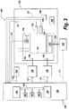
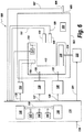
- FIGs. 3 through 6 are schematic block diagrams of environmental chamber systems which use remote sensors such as infrared temperature sensors to directly sense the temperature of the DUT 104.
- the infrared temperature sensor may be of the type manufactured and sold by Exergen Corporation of Watertown, Massachusetts, USA. Other types of infrared temperature sensors may be used according to the disclosure.
- the sensed temperature of the DUT 104 is used as described in detail above to adjust temperature and/or humidity inside the chamber such that condensation at or near the DUT is eliminated or substantially reduced.
- FIG. 3 contains a schematic block diagram of an environmental chamber system 300 using a remote, non-contact DUT temperature sensor 306, according to other exemplary arrangements.
- the chamber system 300 of FIG. 3 is the same as the chamber system 100 of FIG. 1 except that that chamber system 300 of FIG. 3 uses a remote, non-contact infrared DUT temperature sensor 306 instead of the contact temperature sensor 106 in the arrangement of FIG. 1 .
- Elements of the arrangements of FIG. 3 that are the same as elements of the arrangements of FIG. 1 are identified by like reference numerals. Detailed description of these like elements will not be repeated.
- the infrared DUT temperature sensor 306 is positioned and directed such that the DUT 104 is within the field of view of the infrared DUT temperature sensor 306, such that the infrared DUT temperature sensor 306 directly senses the temperature of the DUT 104.
- the sensor 306 generates a signal indicative of the sensed temperature of the DUT 104 and forwards the signal on signal line 307 to the controller 136, which uses the signal as described above in detail to adjust temperature and/or humidity inside the chamber 102 such that condensation at or near the DUT 104 is eliminated or substantially reduced.
- FIG. 4 contains a schematic block diagram of an environmental chamber system 400 using a remote, non-contact DUT temperature sensor 406, according to other exemplary arrangements.
- the chamber system 400 of FIG. 4 is the same as the chamber system 200 of FIG. 2 except that that chamber system 400 of FIG. 4 uses a remote, non-contact infrared DUT temperature sensor 406 instead of the contact temperature sensor 106 in the arrangement of FIG. 2 .
- Elements of the arrangements of FIG. 4 that are the same as elements of the arrangements of FIG. 2 are identified by like reference numerals. Detailed description of these like elements will not be repeated.
- the infrared DUT temperature sensor 406 is positioned and directed such that the DUT 104 is within the field of view of the infrared DUT temperature sensor 406, such that the infrared DUT temperature sensor 406 directly senses the temperature of the DUT 104.
- the sensor 406 generates a signal indicative of the sensed temperature of the DUT 104 and forwards the signal on signal line 407 to the controller 136, which uses the signal as described above in detail to adjust temperature and/or humidity inside the chamber 102 such that condensation at or near the DUT 104 is eliminated or substantially reduced.
- FIG. 5 contains a schematic block diagram of an environmental chamber system 500 using a remote, non-contact DUT temperature sensor 506, according to exemplary embodiments.
- the chamber system 500 of FIG. 5 is the same as the chamber system 300 of FIG. 3 except that, in the chamber system 500 of FIG. 5 , the remote non-contact infrared DUT temperature sensor 506 is outside the chamber 502, in contrast to the system 300 of FIG. 3 in which the infrared DUT temperature sensor 306 is inside the chamber 102.
- Elements of the embodiments of FIG. 5 that are the same as elements of the arrangements of FIG. 3 are identified by like reference numerals. Detailed description of these like elements will not be repeated.
- the infrared DUT temperature sensor 506 is positioned and directed such that the DUT 104 is within the field of view of the infrared DUT temperature sensor 506 through an infrared-transparent window 509 in the chamber 502, such that the infrared DUT temperature sensor 506 directly senses the temperature of the DUT 104.
- the sensor 506 generates a signal indicative of the sensed temperature of the DUT 104 and forwards the signal on signal line 507 to the controller 136, which uses the signal as described above in detail to adjust temperature and/or humidity inside the chamber 502 such that condensation at or near the DUT 104 is eliminated or substantially reduced.
- FIG. 6 contains a schematic block diagram of an environmental chamber system 600 using a remote, non-contact DUT temperature sensor 606, according to other exemplary embodiments.
- the chamber system 600 of FIG. 6 is the same as the chamber system 400 of FIG. 4 except that, in the chamber system 600 of FIG. 6 , the remote non-contact infrared DUT temperature sensor 606 is outside the chamber 602, in contrast to the system 400 of FIG. 4 in which the infrared DUT temperature sensor 406 is inside the chamber 102.
- Elements of the embodiments of FIG. 6 that are the same as elements of the arrangements of FIG. 4 are identified by like reference numerals. Detailed description of these like elements will not be repeated.
- the infrared DUT temperature sensor 606 is positioned and directed such that the DUT 104 is within the field of view of the infrared DUT temperature sensor 606 through an infrared-transparent window 609 in the chamber 602, such that the infrared DUT temperature sensor 606 directly senses the temperature of the DUT 104.
- the sensor 606 generates a signal indicative of the sensed temperature of the DUT 104 and forwards the signal on signal line 607 to the controller 136, which uses the signal as described above in detail to adjust temperature and/or humidity inside the chamber 602 such that condensation at or near the DUT 104 is eliminated or substantially reduced.
- the controller can include a mathematical filter.
- At least one input signal can include two input signals, the two input signals being indicative of humidity and temperature in the chamber.
- At least one control signal can adjust heating in the chamber.
- At least one control signal can adjust cooling in the chamber.
- At least one control signal can be generated to remove moisture from the chamber.
- At least one control signal can be generated to add moisture to the chamber.
Landscapes
- Life Sciences & Earth Sciences (AREA)
- Biodiversity & Conservation Biology (AREA)
- Ecology (AREA)
- Environmental & Geological Engineering (AREA)
- Environmental Sciences (AREA)
- Physics & Mathematics (AREA)
- Health & Medical Sciences (AREA)
- Chemical & Material Sciences (AREA)
- Analytical Chemistry (AREA)
- Biochemistry (AREA)
- General Health & Medical Sciences (AREA)
- General Physics & Mathematics (AREA)
- Immunology (AREA)
- Pathology (AREA)
- Testing Resistance To Weather, Investigating Materials By Mechanical Methods (AREA)
Description
- This application claim priority to
U.S. Patent Application Serial No. 13/281,964 - The present disclosure relates to environmental test systems and methods, and, in particular, to environmental test systems and methods in which temperature and humidity in an environmental chamber are controlled to eliminate condensation at or near the device under test (DUT).
- In conventional humidity-controlled and temperature-controlled chamber systems, a device under test (DUT) can be subjected to various forms of testing regimens under various environments. In a large number of these testing regiments, it is important that condensation not be present at or near the DUT, to ensure accurate testing, prevent failure of or damage to the DUT, or for other reasons. In conventional testing systems, because of the thermal mass of the DUT, or other factors, the temperature of the DUT may be at a temperature that is below the dew point of the controlled chamber environment. As a result, condensation can form, which can result in a spoiled testing regimen.
- The document
US 2007/023536 A1 discloses a humidity control apparatus and methods for use with, e. g., an environmental test chamber. In one embodiment, the apparatus comprises a system having a test chamber, a water tank, motive source for a gaseous humidity carrier, and temperature controllers for the tank and chamber; condensation within the test chamber is reduced or even eliminated. - The document
US 2006/158207 A1 discloses an apparatus and a method for testing semi-conductor wafers by means of a temperature-regulated chuck device, the method comprising controlling the temperature of the chuck device to a predetermined measurement temperature by means of a heating device. - According to one aspect, the present disclosure is directed to an environmental chamber system in which a device under test (DUT) can be tested. The environmental chamber system includes an environmental chamber in which the DUT can be tested. A temperature sensor senses temperature of the DUT and generates a signal indicative of temperature of the DUT. A controller receives at least one input signal related to at least one of temperature and humidity in the chamber and receives the signal indicative of temperature of the DUT. The controller provides at least one control signal for adjusting at least one of temperature and humidity in the chamber, such that the temperature of the DUT is not below a dew point of an environment in the chamber in a region of the chamber near the DUT, such that condensation in the environment in the chamber in the region near the DUT does not occur. The temperature sensor is an infrared temperature sensor, and the DUT is within a field of view of the infrared sensor. The infrared sensor is outside the chamber.
- In some exemplary embodiments, the controller comprises a mathematical filter.
- In some exemplary embodiments, the at least one input signal comprises two input signals, the two input signals being indicative of humidity and temperature in the chamber.
- In some exemplary embodiments, the at least one control signal adjusts heating in the chamber.
- In some exemplary embodiments, the at least one control signal adjusts cooling in the chamber.
- In some exemplary embodiments, the at least one control signal is generated to remove moisture from the chamber.
- In some exemplary embodiments, the at least one control signal is generated to add moisture to the chamber.
- According to another aspect, the present disclosure is directed to a method of testing a device under test (DUT). The method comprises: placing the DUT in an environmental chamber; sensing temperature of the DUT with a temperature sensor, the temperature sensor generating a first signal, the first signal being indicative of temperature of the DUT; sensing at least one of temperature and humidity inside the chamber and generating at least one second signal indicative of the at least one of temperature and humidity inside the chamber; and generating at least one control signal for adjusting at least one of temperature and humidity in the chamber, such that the temperature of the DUT is not below a dew point of an environment in the chamber in a region of the chamber near the DUT, such that condensation in the environment in the chamber in the region near the DUT does not occur, the at least one control signal being based on first signal and the at least one second signal. The temperature sensor is an infrared temperature sensor, and the DUT is within a field of view of the infrared sensor. The infrared sensor is outside the chamber.
- In some exemplary embodiments, the at least one second signal comprises two signals, the two signals being indicative of humidity and temperature in the chamber.
- In some exemplary embodiments, the at least one control signal adjusts heating in the chamber.
- In some exemplary embodiments, the at least one control signal adjusts cooling in the chamber.
- In some exemplary embodiments, the at least one control signal is generated to remove moisture from the chamber.
- In some exemplary embodiments, the at least one control signal is generated to add moisture to the chamber.
- The foregoing and other features and advantages of the disclosure will be apparent from the more particular description of preferred embodiments, as illustrated in the accompanying drawings, in which like reference characters refer to the same parts throughout the different views. The drawings are not necessarily to scale, emphasis instead being placed upon illustrating the principles of the disclosure.
-
FIG. 1 contains a schematic block diagram of an environmental chamber system, useful for understanding the invention. -
FIG. 2 contains a schematic block diagram of an environmental chamber system, useful for understanding the invention. -
FIG. 3 contains a schematic block diagram of an environmental chamber system using a remote, non-contact DUT temperature sensor, useful for understanding the invention. -
FIG. 4 contains a schematic block diagram of an environmental chamber system using a remote, non-contact DUT temperature sensor, useful for understanding the invention. -
FIG. 5 contains a schematic block diagram of an environmental chamber system using a remote, non-contact DUT temperature sensor, according to exemplary embodiments of the invention. -
FIG. 6 contains a schematic block diagram of an environmental chamber system using a remote, non-contact DUT temperature sensor, according to other exemplary embodiments of the invention. -
FIG. 1 contains a schematic block diagram of anenvironmental chamber system 100. Referring toFIG. 1 , thesystem 100 includes an environmentally-controlledchamber 102 in which a device under test (DUT) 104 can be located such that a testing regimen can be carried out on the DUT in certain prescribed environments. For example, in the arrangement illustrated inFIG. 1 , the temperature and humidity inside thechamber 102 is controllable. To that end, thesystem 100 includes atemperature sensor 110 and ahumidity sensor 108 inside thechamber 102. Thetemperature sensor 110 andhumidity sensor 108 sense the temperature and humidity, respectively, inside thechamber 102 and transfer signals indicative of the temperature and humidity, respectively, to asystem controller 136. - The environment inside the
chamber 102 is conditioned such as by adding and/or removing moisture and/or heating and/or cooling the environment using amixing blower 116, which moves the chamber environmental gas, e.g., air, through aplenum 112 located inside thechamber 102. In general, rapid and turbulent air flow through theplenum 112 is achieved by themixing blower 116, under the control of the mixing blower power andcontrol unit 114, which is controlled by a control signal onsignal line 117 from thesystem controller 136. Themixing blower 116 exhausts the flowing air into thechamber 102 to control the environment in thechamber 102. - The air in the
chamber 102 is heated byheater 118. In some exemplary arrangements, theheater 118 is a resistive heater which operates under the control of the heater power andcontrol unit 134, which is controlled by thesystem controller 136 via a control signal onsignal line 135. - In some exemplary arrangements, the air in the
camber 102 is cooled by, for example, anevaporator unit 120. Air from thechamber 102 is drawn into theplenum 112 by themixing blower 116, where theevaporator 120 cools the air. The air entering theplenum 112 can be cooled by theevaporator 120 either mechanically, i.e., by a refrigeration cycle operating in concert with theevaporator 120, or cryogenically by the injection of a cryogenic material into theevaporator 120. In the exemplary arrangement illustrated inFIG. 1 , theevaporator 120 cools the air by injection of a cryogenic material, which can be, for example, liquid nitrogen (LNz), liquid carbon dioxide LCOz, or other such material. The LNz or LCOz is transported from asource 122 through the wall of thechamber 102 via a pipe ortubing 124, and into theevaporator 120. The transport of the cooling material is controlled by thesystem controller 136 via a control signal onsignal line 131 as shown inFIG. 1 . As the injected material enters theevaporator 120, it evaporates, thus cooling the air flowing along the outer surface of theevaporator 120. - As noted above, in some exemplary arrangements, humidity in the
chamber 102 is also controlled. Accordingly, thesystem 100 also includes a moisture input for adding humidity to the environment inside thechamber 102 and a drying input for removing humidity from the environment inside thechamber 102. In some exemplary arrangements, the moisture input may be, for example, atomized water, which is transported from asource 126 through the wall of thechamber 102 via a pipe ortubing 130, and into theplenum 112. The flow and/or the flow rate of the atomized water, and, therefore, the humidity adjustment made by the atomized water, is controlled by thesystem controller 136 via a control signal onsignal line 127, as shown inFIG. 1 . In some exemplary arrangements, the drying input may be, for example, dry nitrogen, which is transported from asource 128 through the wall of thechamber 102 via a pipe ortubing 132, and into theplenum 112. The flow and/or the flow rate of the dry nitrogen, and, therefore, the humidity adjustment made by the dry nitrogen, is controlled by thesystem controller 136 via a control signal onsignal line 129, as shown inFIG. 1 . - Either or both of the moisture input and the drying input are introduced into the turbulent air flow in the
plenum 112. According to the disclosure, thesystem controller 136, via the appropriate control signals, sets the combination of the moisture input and the drying input as desired to achieve the desired humidity in thechamber 102, as measured by thehumidity sensor 108. Similarly, either or both of theheating 118 and cooling 120 are introduced into the turbulent air flow in theplenum 112. According to the disclosure, thesystem controller 136, via the appropriate control signals, sets the combination of the heating input and cooling input as desired to achieve the desired temperature in thechamber 102. - The
system 100 also includes aDUT temperature sensor 106 located in close proximity to and/or in contact with theDUT 104. TheDUT temperature sensor 106 directly senses the temperature of theDUT 104 in situ, independent of any potential influence by any other factors, such as, for example, temperature variations/gradients in the chamber environment. TheDUT temperature sensor 106 senses the temperature of theDUT 104 in situ and forwards a signal indicative of the temperature of theDUT 104 to thesystem controller 136 onsignal line 107. In some exemplary arrangements, theDUT temperature sensor 106 can be or include a resistance to temperature (RTD) device, a thermocouple, a thermistor, or other such contact temperature sensing device. - The
system controller 136 controls the operation of thesystem 100 by processing the various input signals it receives from the various sensors in the system and generating control signals using the input signals. In some exemplary arrangements, thesystem controller 136 includes aprocessing device 140, which can be a microprocessor, a microcontroller, a programmed gate array, or other such device.System controller 136 also includesmemory circuits memory circuits system controller 136 to control thesystem 100. Thesystem controller 136 also includesperipheral circuitry 148 associated with theprocessing device 140 andmemories peripheral circuitry 148 may include, for example, input/output interface circuitry, mathematical operations circuitry, or other circuitry used to carry out the functions of thesystem controller 136 together with theprocessing device 140 and thememories processing device 140, thememories peripheral circuitry 148 are connected via asystem bus 150. Signals among theprocessing device 140,memories peripheral circuitry 148 are carried over thesystem bus 150. - As described above, the
system 100 operates to eliminate condensation at or near theDUT 104 during testing. This is achieved by obtaining an accurate in-situ measurement of the temperature of theDUT 104, via theDUT temperature sensor 106, in addition to accurate measurements of chamber humidity via thehumidity sensor 108 and accurate measurements of chamber temperature via thetemperature sensor 110. By directly sensing the actual temperature of theDUT 104 in situ, the system can make adjustments to the humidity and temperature in thechamber 102 to ensure that the temperature of theDUT 104 is not below the dew point of the air in thechamber 102, which eliminates condensation at or near theDUT 104. - The
system controller 136, through theprocessing device 140,memories peripheral circuitry 148, controls thesystem 100 by executing a control process or function. In some exemplary arrangements, the control process or function can be or can include a mathematical filter. The control process or function receives as input variables the temperature of theDUT 104 viasignal line 107, the temperature of thechamber 102 viasignal line 111 and the humidity of thechamber 102 viasignal line 109. The control process or function processes these received signals and produces a set of control signals to control the humidity and temperature of thechamber 102 such that condensation does not occur at or near theDUT 104. - Specifically, the control process or function generates a heating control signal on
control signal line 135 to command heating as required via the heating power andcontrol unit 134. The control signal can command theheater 118 between on and off states, or it may adjust the power supplied to theheater 118 to adjust the output heat. Similarly, the control process or function generates a cooling control signal onsignal line 131 to command cooling as required via thecooling source 122. The control signal can command thesource 122 between on and off states such that the flow of cryogenic material, e.g., LNz or LCOz, switches between flowing and not flowing, or it may adjust the flow rate of the LNz or LCOz to adjust the cooling. Similarly, the control process or function generates a moisture control signal onsignal line 127 to command the addition of moisture to the air in thechamber 102 as required via themoisture source 126. As noted above, the moisture source may be a source of atomized water. The control signal can command thesource 126 between on and off states such that the flow of moisture, i.e., atomized water, switches between flowing and not flowing, or it may adjust the flow rate of the atomized water. Similarly, the control process or function generates a drying control signal onsignal line 129 to command the reduction of moisture in the air in thechamber 102 as required via the dryingsource 128. As noted above, the dryingsource 128 may be a source of dry nitrogen. The control signal can command thesource 128 between on and off states such that the flow of dry nitrogen switches between flowing and not flowing, or it may adjust the flow rate of the dry nitrogen. The control process or function also generates a control signal onsignal line 117, which controls themixing blower 116 via the mixing blower power andcontrol unit 114, to control flow and mixture of the environmental gas, i.e., air, inside thechamber 102. - In some exemplary arrangements, the
system controller 136 is also provided with an enable input onsignal line 138. The enable input can be used to enable or disable the elimination of condensation at theDUT 104. The enable input can also be an adjustment signal which allows the user to set a desired or acceptable level of condensation at theDUT 104, rather than completely eliminating condensation. This acceptable level signal is used by the control process or function in generating the various control signals described in detail above such that the acceptable level of condensation is achieved. -
FIG. 2 contains a schematic block diagram of an environmental chamber system, according to other exemplary arrangements. The difference between the arrangements ofFIG. 2 and the arrangements ofFIG. 1 is that, in the arrangements ofFIG. 1 , cooling is achieved by injecting cryogenic material into theevaporator 120, whereas, in the arrangements ofFIG. 2 , the cooling is achieved by mechanical refrigeration, i.e., by a mechanical refrigeration cycle, and theevaporator 220 of the arrangements ofFIG. 2 is part of the mechanical refrigeration cycle. - Elements, functions and processes of the arrangements of
FIG. 2 that are the same as those of the arrangements ofFIG. 1 are identified by like reference numerals. Detailed description of these like elements, functions and processes will not be repeated. - Referring to
FIG. 2 , in some exemplary arrangements, the air in thechamber 102 is cooled by, for example, anevaporator unit 220. Air from thechamber 102 is drawn into theplenum 112 by the mixingblower 116, where theevaporator 220 cools the air. In these arrangements, the air entering theplenum 112 is cooled by theevaporator 220 mechanically, i.e., by a refrigeration cycle operating in concert with theevaporator 220. The mechanical refrigeration cycle components are indicated generally by 222. Refrigerant in the refrigeration cycle is transported from the remainder of therefrigeration cycle 222 through the wall of thechamber 102 via a pipe ortubing 224, and into theevaporator 220. The transport of the refrigerant is controlled by thesystem controller 136 via a control signal onsignal line 231 as shown inFIG. 2 . As the refrigerant enters theevaporator 220, it evaporates, thus cooling the air flowing along the outer surface of theevaporator 220. - According to exemplary arrangements, the control process or function generates a cooling control signal on
signal line 231 to command cooling as required via therefrigeration cycle 222. The control signal can command thecycle 222 between on and off states such that the flow of refrigerant switches between flowing and not flowing, or it may adjust the flow rate of the refrigerant to adjust the cooling. - In the arrangements described above, the
DUT temperature sensor 106 is disclosed as being a contact temperature sensor in direct contact with or immediately adjacent to theDUT 104 such that temperature of theDUT 104 is sensed directly. According to the disclosure, other non-contact types of temperature sensors can be used to sense the temperature of theDUT 104 directly. For example, temperature of theDUT 104 may be sensed directly using an infrared temperature sensor, which can be located some distance from theDUT 104 and does not make contact with theDUT 104. The infrared temperature sensor of these arrangements may be located inside the chamber or in certain embodiments outside the chamber. -
FIGs. 3 through 6 are schematic block diagrams of environmental chamber systems which use remote sensors such as infrared temperature sensors to directly sense the temperature of theDUT 104. In any of the arrangements or embodiments described herein, the infrared temperature sensor may be of the type manufactured and sold by Exergen Corporation of Watertown, Massachusetts, USA. Other types of infrared temperature sensors may be used according to the disclosure. The sensed temperature of theDUT 104 is used as described in detail above to adjust temperature and/or humidity inside the chamber such that condensation at or near the DUT is eliminated or substantially reduced. -
FIG. 3 contains a schematic block diagram of anenvironmental chamber system 300 using a remote, non-contactDUT temperature sensor 306, according to other exemplary arrangements. Thechamber system 300 ofFIG. 3 is the same as thechamber system 100 ofFIG. 1 except that thatchamber system 300 ofFIG. 3 uses a remote, non-contact infraredDUT temperature sensor 306 instead of thecontact temperature sensor 106 in the arrangement ofFIG. 1 . Elements of the arrangements ofFIG. 3 that are the same as elements of the arrangements ofFIG. 1 are identified by like reference numerals. Detailed description of these like elements will not be repeated. - Referring to
FIG. 3 , the infraredDUT temperature sensor 306 is positioned and directed such that theDUT 104 is within the field of view of the infraredDUT temperature sensor 306, such that the infraredDUT temperature sensor 306 directly senses the temperature of theDUT 104. Thesensor 306 generates a signal indicative of the sensed temperature of theDUT 104 and forwards the signal onsignal line 307 to thecontroller 136, which uses the signal as described above in detail to adjust temperature and/or humidity inside thechamber 102 such that condensation at or near theDUT 104 is eliminated or substantially reduced. -
FIG. 4 contains a schematic block diagram of anenvironmental chamber system 400 using a remote, non-contactDUT temperature sensor 406, according to other exemplary arrangements. Thechamber system 400 ofFIG. 4 is the same as thechamber system 200 ofFIG. 2 except that thatchamber system 400 ofFIG. 4 uses a remote, non-contact infraredDUT temperature sensor 406 instead of thecontact temperature sensor 106 in the arrangement ofFIG. 2 . Elements of the arrangements ofFIG. 4 that are the same as elements of the arrangements ofFIG. 2 are identified by like reference numerals. Detailed description of these like elements will not be repeated. - Referring to
FIG. 4 , the infraredDUT temperature sensor 406 is positioned and directed such that theDUT 104 is within the field of view of the infraredDUT temperature sensor 406, such that the infraredDUT temperature sensor 406 directly senses the temperature of theDUT 104. Thesensor 406 generates a signal indicative of the sensed temperature of theDUT 104 and forwards the signal onsignal line 407 to thecontroller 136, which uses the signal as described above in detail to adjust temperature and/or humidity inside thechamber 102 such that condensation at or near theDUT 104 is eliminated or substantially reduced. -
FIG. 5 contains a schematic block diagram of anenvironmental chamber system 500 using a remote, non-contactDUT temperature sensor 506, according to exemplary embodiments. Thechamber system 500 ofFIG. 5 is the same as thechamber system 300 ofFIG. 3 except that, in thechamber system 500 ofFIG. 5 , the remote non-contact infraredDUT temperature sensor 506 is outside thechamber 502, in contrast to thesystem 300 ofFIG. 3 in which the infraredDUT temperature sensor 306 is inside thechamber 102. Elements of the embodiments ofFIG. 5 that are the same as elements of the arrangements ofFIG. 3 are identified by like reference numerals. Detailed description of these like elements will not be repeated. - Referring to
FIG. 5 , the infraredDUT temperature sensor 506 is positioned and directed such that theDUT 104 is within the field of view of the infraredDUT temperature sensor 506 through an infrared-transparent window 509 in thechamber 502, such that the infraredDUT temperature sensor 506 directly senses the temperature of theDUT 104. Thesensor 506 generates a signal indicative of the sensed temperature of theDUT 104 and forwards the signal onsignal line 507 to thecontroller 136, which uses the signal as described above in detail to adjust temperature and/or humidity inside thechamber 502 such that condensation at or near theDUT 104 is eliminated or substantially reduced. -
FIG. 6 contains a schematic block diagram of anenvironmental chamber system 600 using a remote, non-contactDUT temperature sensor 606, according to other exemplary embodiments. Thechamber system 600 ofFIG. 6 is the same as thechamber system 400 ofFIG. 4 except that, in thechamber system 600 ofFIG. 6 , the remote non-contact infraredDUT temperature sensor 606 is outside the chamber 602, in contrast to thesystem 400 ofFIG. 4 in which the infraredDUT temperature sensor 406 is inside thechamber 102. Elements of the embodiments ofFIG. 6 that are the same as elements of the arrangements ofFIG. 4 are identified by like reference numerals. Detailed description of these like elements will not be repeated. - Referring to
FIG. 6 , the infraredDUT temperature sensor 606 is positioned and directed such that theDUT 104 is within the field of view of the infraredDUT temperature sensor 606 through an infrared-transparent window 609 in the chamber 602, such that the infraredDUT temperature sensor 606 directly senses the temperature of theDUT 104. Thesensor 606 generates a signal indicative of the sensed temperature of theDUT 104 and forwards the signal onsignal line 607 to thecontroller 136, which uses the signal as described above in detail to adjust temperature and/or humidity inside the chamber 602 such that condensation at or near theDUT 104 is eliminated or substantially reduced. - Various features of the present disclosure have been described above in detail. The following examples illustrate some of the combinations of features contemplated and disclosed herein in accordance with this disclosure.
- In any of the embodiments described in detail and/or claimed herein, the controller can include a mathematical filter.
- In any of the embodiments described in detail and/or claimed herein, at least one input signal can include two input signals, the two input signals being indicative of humidity and temperature in the chamber.
- In any of the embodiments described in detail and/or claimed herein, at least one control signal can adjust heating in the chamber.
- In any of the embodiments described in detail and/or claimed herein, at least one control signal can adjust cooling in the chamber.
- In any of the embodiments described in detail and/or claimed herein, at least one control signal can be generated to remove moisture from the chamber.
- In any of the embodiments described in detail and/or claimed herein, at least one control signal can be generated to add moisture to the chamber.
- While the present disclosure has made reference to exemplary embodiments, it will be understood by those of ordinary skill in the art that various changes in form and details may be made therein without departing from the scope of the present disclosure as defined by the following claims.
Claims (13)
- An environmental chamber system (500) in which a device under test (DUT) (104) can be tested, the environmental chamber system comprising:an environmental chamber (502) in which the DUT can be tested;a temperature sensor (506) for sensing temperature of the DUT, the temperature sensor generating a signal indicative of temperature of the DUT, the temperature sensor being an infrared temperature sensor located outside the chamber, the DUT being within a field of view of the infrared temperature sensor; anda controller (136) for receiving at least one input signal related to at least one of temperature and humidity in the chamber and receiving the signal indicative of temperature of the DUT and providing at least one control signal for adjusting at least one of temperature and humidity in the chamber, such that the temperature of the DUT is not below a dew point of an environment in the chamber in a region of the chamber near the DUT, such that condensation in the environment in the chamber in the region near the DUT does not occur.
- The system of claim 1, wherein the controller comprises a mathematical filter.
- The system of claim 1, wherein the at least one input signal comprises two input signals, the two input signals being indicative of humidity and temperature in the chamber.
- The system of claim 1, wherein the at least one control signal adjusts heating in the chamber.
- The system of claim 1, wherein the at least one control signal adjusts cooling in the chamber.
- The system of claim 1, wherein the at least one control signal is generated to remove moisture from the chamber.
- The system of claim 1, wherein the at least one control signal is generated to add moisture to the chamber.
- A method of testing a device under test (DUT) (104), comprising:placing the DUT in an environmental chamber (502);sensing temperature of the DUT with a temperature sensor (506), the temperature sensor generating a first signal, the first signal being indicative of temperature of the DUT, the temperature sensor being an infrared temperature sensor located outside the environmental chamber, the DUT being within a field of view of the infrared temperature sensor;sensing at least one of temperature and humidity inside the chamber and generating at least one second signal indicative of the at least one of temperature and humidity inside the chamber; andgenerating at least one control signal for adjusting at least one of temperature and humidity in the chamber, such that the temperature of the DUT is not below a dew point of an environment in the chamber in a region of the chamber near the DUT, such that condensation in the environment in the chamber in the region near the DUT does not occur, the at least one control signal being based on first signal and the at least one second signal.
- The method of claim 8, wherein the at least one second signal comprises two signals, the two signals being indicative of humidity and temperature in the chamber.
- The method of claim 8, wherein the at least one control signal adjusts heating in the chamber.
- The method of claim 8, wherein the at least one control signal adjusts cooling in the chamber.
- The method of claim 8, wherein the at least one control signal is generated to remove moisture from the chamber.
- The method of claim 8, wherein the at least one control signal is generated to add moisture to the chamber.
Applications Claiming Priority (2)
| Application Number | Priority Date | Filing Date | Title |
|---|---|---|---|
| US13/281,964 US8602641B2 (en) | 2011-10-26 | 2011-10-26 | Environmental test system and method with in-situ temperature sensing of device under test (DUT) |
| PCT/US2012/062178 WO2013063437A1 (en) | 2011-10-26 | 2012-10-26 | Environmental test system and method with in-situ temperature sensing of device under test (dut) |
Publications (2)
| Publication Number | Publication Date |
|---|---|
| EP2771668A1 EP2771668A1 (en) | 2014-09-03 |
| EP2771668B1 true EP2771668B1 (en) | 2018-10-03 |
Family
ID=47221550
Family Applications (1)
| Application Number | Title | Priority Date | Filing Date |
|---|---|---|---|
| EP12790725.1A Active EP2771668B1 (en) | 2011-10-26 | 2012-10-26 | Environmental test system and method with in-situ temperature sensing of device under test (dut) |
Country Status (7)
| Country | Link |
|---|---|
| US (2) | US8602641B2 (en) |
| EP (1) | EP2771668B1 (en) |
| JP (2) | JP2014532867A (en) |
| CN (1) | CN104114996A (en) |
| MY (1) | MY167932A (en) |
| SG (1) | SG11201401808TA (en) |
| WO (1) | WO2013063437A1 (en) |
Families Citing this family (4)
| Publication number | Priority date | Publication date | Assignee | Title |
|---|---|---|---|---|
| TWI606242B (en) * | 2015-09-17 | 2017-11-21 | 旺矽科技股份有限公司 | Temperature control system and method thereof |
| GB2553592B (en) | 2016-09-13 | 2019-03-27 | Catagen Ltd | Test system with recirculating fluid reactor |
| JP7316798B2 (en) | 2019-01-30 | 2023-07-28 | 株式会社アドバンテスト | Electronic component handling equipment and electronic component testing equipment |
| CN110794277B (en) * | 2018-07-26 | 2022-06-03 | 株式会社爱德万测试 | Electronic component handling apparatus and electronic component testing apparatus |
Citations (2)
| Publication number | Priority date | Publication date | Assignee | Title |
|---|---|---|---|---|
| US20050089076A1 (en) * | 2003-10-28 | 2005-04-28 | Flir Systems Ab | Use of IR camera |
| JP2010181221A (en) * | 2009-02-04 | 2010-08-19 | Espec Corp | Dew condensation testing device |
Family Cites Families (33)
| Publication number | Priority date | Publication date | Assignee | Title |
|---|---|---|---|---|
| US3424231A (en) * | 1967-03-23 | 1969-01-28 | Andrew Truhan | Environmental chamber |
| US3538750A (en) * | 1968-04-26 | 1970-11-10 | Panametrics | High temperature ultrasonic measuring system |
| US3687612A (en) * | 1970-10-12 | 1972-08-29 | Sybron Corp | Method of controlling relative humidity in gaseous sterilizers |
| US3870873A (en) * | 1971-04-07 | 1975-03-11 | Mbr Corp | Environmental chamber |
| US4154089A (en) * | 1978-06-12 | 1979-05-15 | The United States Of America As Represented By The Secretary Of The Army | Apparatus and method for measuring liquid water content of a cloud or fog |
| US4196839A (en) * | 1978-06-29 | 1980-04-08 | International Telephone And Telegraph Corporation | Methods of fabricating printed circuit boards |
| US4185497A (en) * | 1978-10-02 | 1980-01-29 | The United States Of America As Represented By The Secretary Of The Navy | Adiabatic laser calorimeter |
| US4381154A (en) * | 1980-09-26 | 1983-04-26 | The Hetra Corporation | Method of and apparatus for nondestructively determining the composition of an unknown material sample |
| US4602503A (en) * | 1985-07-11 | 1986-07-29 | Parameter Generation & Control, Inc. | Environmental chamber |
| JPH0310140A (en) * | 1989-06-08 | 1991-01-17 | Fujitsu Ltd | Dew-condensation preventing device in low-temperature testing apparatus |
| US5263775A (en) * | 1991-02-01 | 1993-11-23 | Aetrium, Inc. | Apparatus for handling devices under varying temperatures |
| US5440566A (en) * | 1991-09-23 | 1995-08-08 | Southwest Research Institute | Fault detection and diagnosis for printed circuit boards |
| JP2930109B2 (en) * | 1996-09-19 | 1999-08-03 | 日本電気株式会社 | Low temperature test method and low temperature test equipment |
| JPH11183361A (en) * | 1997-12-22 | 1999-07-09 | Canon Inc | High-temperature and high-humidity test apparatus and its heating and humidifying method |
| JP3375305B2 (en) * | 1999-07-22 | 2003-02-10 | ダイキンプラント株式会社 | Environmental test equipment |
| US6526841B1 (en) * | 1999-08-02 | 2003-03-04 | Pemstar, Inc. | Environmental test chamber and a carrier for use therein |
| US6911016B2 (en) * | 2001-08-06 | 2005-06-28 | Scimed Life Systems, Inc. | Guidewire extension system |
| US6957026B2 (en) * | 2004-02-18 | 2005-10-18 | Xerox Corporation | Dual airflow environmental module to provide balanced and thermodynamically adjusted airflows for a device |
| US7330041B2 (en) * | 2004-06-14 | 2008-02-12 | Cascade Microtech, Inc. | Localizing a temperature of a device for testing |
| DE102005001163B3 (en) | 2005-01-10 | 2006-05-18 | Erich Reitinger | Semiconductor wafers` testing method, involves testing wafer by probes, and reducing heating energy with constant cooling efficiency, under consideration of detected increase of temperature of fluids flowing via tempered chuck device |
| US20060254372A1 (en) * | 2005-05-16 | 2006-11-16 | Kurt Scott | Non-contact temperature sensor for a weathering test device |
| EP1894074A4 (en) * | 2005-06-13 | 2010-05-19 | Sigma Systems Corp | Methods and apparatus for optimizing environmental humidity |
| JP3806764B1 (en) * | 2005-12-28 | 2006-08-09 | スガ試験機株式会社 | Constant temperature weather test method and weather test machine |
| JP2008133079A (en) * | 2006-11-28 | 2008-06-12 | Kyocera Mita Corp | Sheet feeder |
| US7719693B2 (en) * | 2007-04-23 | 2010-05-18 | The Aerospace Corporation | Interferometry system chamber viewing window |
| US7806585B2 (en) * | 2007-06-22 | 2010-10-05 | Decagon Devices, Inc. | Apparatus, method, and system for measuring water activity and weight |
| JP5180688B2 (en) * | 2008-06-04 | 2013-04-10 | エスペック株式会社 | Constant temperature and humidity device |
| KR100948587B1 (en) * | 2008-08-27 | 2010-03-18 | 한국원자력연구원 | High Frequency Induction Heating Apparatus of Ceramic Material and Non-Pressure Sintering Method Using the Same |
| JP2010085346A (en) * | 2008-10-02 | 2010-04-15 | Espec Corp | Environmental testing device having dew condensation control mechanism for test object surface |
| JP2011002372A (en) * | 2009-06-19 | 2011-01-06 | Espec Corp | Device and method for testing conduction deterioration |
| CN101858876B (en) * | 2010-06-01 | 2012-03-21 | 东莞市升微机电设备科技有限公司 | Detection system and humidity detection method for detecting volatile organic compounds |
| TW201239282A (en) * | 2011-03-16 | 2012-10-01 | Hon Hai Prec Ind Co Ltd | System and method for controlling an environmental chamber |
| US20140295771A1 (en) * | 2013-03-28 | 2014-10-02 | Qualcomm Incorporated | Off-line device testing using video and audio code control |
-
2011
- 2011-10-26 US US13/281,964 patent/US8602641B2/en not_active Expired - Fee Related
-
2012
- 2012-10-26 EP EP12790725.1A patent/EP2771668B1/en active Active
- 2012-10-26 MY MYPI2014001198A patent/MY167932A/en unknown
- 2012-10-26 WO PCT/US2012/062178 patent/WO2013063437A1/en not_active Ceased
- 2012-10-26 JP JP2014539056A patent/JP2014532867A/en active Pending
- 2012-10-26 CN CN201280064508.7A patent/CN104114996A/en active Pending
- 2012-10-26 SG SG11201401808TA patent/SG11201401808TA/en unknown
-
2013
- 2013-11-04 US US14/070,916 patent/US20140064323A1/en not_active Abandoned
-
2016
- 2016-09-28 JP JP2016189289A patent/JP2017032575A/en active Pending
Patent Citations (2)
| Publication number | Priority date | Publication date | Assignee | Title |
|---|---|---|---|---|
| US20050089076A1 (en) * | 2003-10-28 | 2005-04-28 | Flir Systems Ab | Use of IR camera |
| JP2010181221A (en) * | 2009-02-04 | 2010-08-19 | Espec Corp | Dew condensation testing device |
Also Published As
| Publication number | Publication date |
|---|---|
| US20140064323A1 (en) | 2014-03-06 |
| EP2771668A1 (en) | 2014-09-03 |
| US8602641B2 (en) | 2013-12-10 |
| SG11201401808TA (en) | 2014-05-29 |
| JP2014532867A (en) | 2014-12-08 |
| JP2017032575A (en) | 2017-02-09 |
| US20130107906A1 (en) | 2013-05-02 |
| MY167932A (en) | 2018-10-04 |
| WO2013063437A1 (en) | 2013-05-02 |
| CN104114996A (en) | 2014-10-22 |
Similar Documents
| Publication | Publication Date | Title |
|---|---|---|
| US7271604B2 (en) | Method and apparatus for testing semiconductor wafers by means of a temperature-regulated chuck device | |
| TWI281694B (en) | Control process, temperature control process, temperature regulator, heat treatment and recordable medium | |
| US8602641B2 (en) | Environmental test system and method with in-situ temperature sensing of device under test (DUT) | |
| SE0002690D0 (en) | Device and method for temperature control and ventilation of a seat | |
| JP2007521986A (en) | Method and apparatus for measuring and controlling both the inner and outer surface temperatures of a thermoplastic preform during a stretch blow molding operation | |
| US20140341253A1 (en) | Anomaly detector and environmental tester including the same | |
| US6971793B2 (en) | Test handler temperature monitoring system | |
| JP2015203612A (en) | Environment test device and temperature-humidity control method | |
| EP3819616B1 (en) | Improving, detecting and indicating stability in an industrial temperature dry block calibrator | |
| WO2004017035A2 (en) | Method and apparatus for temperature control | |
| MX2010011596A (en) | Device and method for thermally treating workpieces in particular by convective heat transfer. | |
| US20090030560A1 (en) | Temperature control system for machine tool | |
| US5884235A (en) | Non-contact, zero-flux temperature sensor | |
| CN106020277A (en) | Work temperature control method and casing of low-temperature friction wear machine | |
| JPH02105046A (en) | Analyzing device | |
| JP6401350B2 (en) | Calibration method of temperature adjustment during thermal analysis of sample | |
| KR101013520B1 (en) | Test Handler Chamber Rapid Temperature Control | |
| JP2004273967A (en) | Chamber temperature control system | |
| JP2001051012A (en) | Semiconductor test system and test temperature stably control method | |
| KR100888054B1 (en) | Wafer testing system comprising chiller | |
| JP7729323B2 (en) | Heating furnace simulation system | |
| JP5167008B2 (en) | Condensation amount controllable environment test apparatus and method for controlling condensation amount | |
| JPH03269353A (en) | Surface flaw detector | |
| JP2998557B2 (en) | Room temperature controller for constant temperature bath | |
| KR100789699B1 (en) | Hot and cold testable wafer prober device |
Legal Events
| Date | Code | Title | Description |
|---|---|---|---|
| PUAI | Public reference made under article 153(3) epc to a published international application that has entered the european phase |
Free format text: ORIGINAL CODE: 0009012 |
|
| 17P | Request for examination filed |
Effective date: 20140509 |
|
| AK | Designated contracting states |
Kind code of ref document: A1 Designated state(s): AL AT BE BG CH CY CZ DE DK EE ES FI FR GB GR HR HU IE IS IT LI LT LU LV MC MK MT NL NO PL PT RO RS SE SI SK SM TR |
|
| DAX | Request for extension of the european patent (deleted) | ||
| GRAP | Despatch of communication of intention to grant a patent |
Free format text: ORIGINAL CODE: EPIDOSNIGR1 |
|
| STAA | Information on the status of an ep patent application or granted ep patent |
Free format text: STATUS: GRANT OF PATENT IS INTENDED |
|
| INTG | Intention to grant announced |
Effective date: 20180423 |
|
| GRAS | Grant fee paid |
Free format text: ORIGINAL CODE: EPIDOSNIGR3 |
|
| GRAA | (expected) grant |
Free format text: ORIGINAL CODE: 0009210 |
|
| STAA | Information on the status of an ep patent application or granted ep patent |
Free format text: STATUS: THE PATENT HAS BEEN GRANTED |
|
| AK | Designated contracting states |
Kind code of ref document: B1 Designated state(s): AL AT BE BG CH CY CZ DE DK EE ES FI FR GB GR HR HU IE IS IT LI LT LU LV MC MK MT NL NO PL PT RO RS SE SI SK SM TR |
|
| REG | Reference to a national code |
Ref country code: GB Ref legal event code: FG4D |
|
| REG | Reference to a national code |
Ref country code: CH Ref legal event code: EP Ref country code: AT Ref legal event code: REF Ref document number: 1049126 Country of ref document: AT Kind code of ref document: T Effective date: 20181015 |
|
| REG | Reference to a national code |
Ref country code: DE Ref legal event code: R096 Ref document number: 602012051799 Country of ref document: DE Ref country code: IE Ref legal event code: FG4D |
|
| REG | Reference to a national code |
Ref country code: NL Ref legal event code: MP Effective date: 20181003 |
|
| REG | Reference to a national code |
Ref country code: LT Ref legal event code: MG4D |
|
| REG | Reference to a national code |
Ref country code: AT Ref legal event code: MK05 Ref document number: 1049126 Country of ref document: AT Kind code of ref document: T Effective date: 20181003 |
|
| PG25 | Lapsed in a contracting state [announced via postgrant information from national office to epo] |
Ref country code: NL Free format text: LAPSE BECAUSE OF FAILURE TO SUBMIT A TRANSLATION OF THE DESCRIPTION OR TO PAY THE FEE WITHIN THE PRESCRIBED TIME-LIMIT Effective date: 20181003 |
|
| PG25 | Lapsed in a contracting state [announced via postgrant information from national office to epo] |
Ref country code: ES Free format text: LAPSE BECAUSE OF FAILURE TO SUBMIT A TRANSLATION OF THE DESCRIPTION OR TO PAY THE FEE WITHIN THE PRESCRIBED TIME-LIMIT Effective date: 20181003 Ref country code: LV Free format text: LAPSE BECAUSE OF FAILURE TO SUBMIT A TRANSLATION OF THE DESCRIPTION OR TO PAY THE FEE WITHIN THE PRESCRIBED TIME-LIMIT Effective date: 20181003 Ref country code: CZ Free format text: LAPSE BECAUSE OF FAILURE TO SUBMIT A TRANSLATION OF THE DESCRIPTION OR TO PAY THE FEE WITHIN THE PRESCRIBED TIME-LIMIT Effective date: 20181003 Ref country code: LT Free format text: LAPSE BECAUSE OF FAILURE TO SUBMIT A TRANSLATION OF THE DESCRIPTION OR TO PAY THE FEE WITHIN THE PRESCRIBED TIME-LIMIT Effective date: 20181003 Ref country code: HR Free format text: LAPSE BECAUSE OF FAILURE TO SUBMIT A TRANSLATION OF THE DESCRIPTION OR TO PAY THE FEE WITHIN THE PRESCRIBED TIME-LIMIT Effective date: 20181003 Ref country code: BG Free format text: LAPSE BECAUSE OF FAILURE TO SUBMIT A TRANSLATION OF THE DESCRIPTION OR TO PAY THE FEE WITHIN THE PRESCRIBED TIME-LIMIT Effective date: 20190103 Ref country code: PL Free format text: LAPSE BECAUSE OF FAILURE TO SUBMIT A TRANSLATION OF THE DESCRIPTION OR TO PAY THE FEE WITHIN THE PRESCRIBED TIME-LIMIT Effective date: 20181003 Ref country code: FI Free format text: LAPSE BECAUSE OF FAILURE TO SUBMIT A TRANSLATION OF THE DESCRIPTION OR TO PAY THE FEE WITHIN THE PRESCRIBED TIME-LIMIT Effective date: 20181003 Ref country code: NO Free format text: LAPSE BECAUSE OF FAILURE TO SUBMIT A TRANSLATION OF THE DESCRIPTION OR TO PAY THE FEE WITHIN THE PRESCRIBED TIME-LIMIT Effective date: 20190103 Ref country code: IS Free format text: LAPSE BECAUSE OF FAILURE TO SUBMIT A TRANSLATION OF THE DESCRIPTION OR TO PAY THE FEE WITHIN THE PRESCRIBED TIME-LIMIT Effective date: 20190203 Ref country code: AT Free format text: LAPSE BECAUSE OF FAILURE TO SUBMIT A TRANSLATION OF THE DESCRIPTION OR TO PAY THE FEE WITHIN THE PRESCRIBED TIME-LIMIT Effective date: 20181003 |
|
| PG25 | Lapsed in a contracting state [announced via postgrant information from national office to epo] |
Ref country code: GR Free format text: LAPSE BECAUSE OF FAILURE TO SUBMIT A TRANSLATION OF THE DESCRIPTION OR TO PAY THE FEE WITHIN THE PRESCRIBED TIME-LIMIT Effective date: 20190104 Ref country code: SE Free format text: LAPSE BECAUSE OF FAILURE TO SUBMIT A TRANSLATION OF THE DESCRIPTION OR TO PAY THE FEE WITHIN THE PRESCRIBED TIME-LIMIT Effective date: 20181003 Ref country code: AL Free format text: LAPSE BECAUSE OF FAILURE TO SUBMIT A TRANSLATION OF THE DESCRIPTION OR TO PAY THE FEE WITHIN THE PRESCRIBED TIME-LIMIT Effective date: 20181003 Ref country code: RS Free format text: LAPSE BECAUSE OF FAILURE TO SUBMIT A TRANSLATION OF THE DESCRIPTION OR TO PAY THE FEE WITHIN THE PRESCRIBED TIME-LIMIT Effective date: 20181003 Ref country code: PT Free format text: LAPSE BECAUSE OF FAILURE TO SUBMIT A TRANSLATION OF THE DESCRIPTION OR TO PAY THE FEE WITHIN THE PRESCRIBED TIME-LIMIT Effective date: 20190203 |
|
| REG | Reference to a national code |
Ref country code: CH Ref legal event code: PL |
|
| REG | Reference to a national code |
Ref country code: BE Ref legal event code: MM Effective date: 20181031 |
|
| PG25 | Lapsed in a contracting state [announced via postgrant information from national office to epo] |
Ref country code: LU Free format text: LAPSE BECAUSE OF NON-PAYMENT OF DUE FEES Effective date: 20181026 |
|
| REG | Reference to a national code |
Ref country code: DE Ref legal event code: R097 Ref document number: 602012051799 Country of ref document: DE |
|
| REG | Reference to a national code |
Ref country code: IE Ref legal event code: MM4A |
|
| PG25 | Lapsed in a contracting state [announced via postgrant information from national office to epo] |
Ref country code: DK Free format text: LAPSE BECAUSE OF FAILURE TO SUBMIT A TRANSLATION OF THE DESCRIPTION OR TO PAY THE FEE WITHIN THE PRESCRIBED TIME-LIMIT Effective date: 20181003 Ref country code: IT Free format text: LAPSE BECAUSE OF FAILURE TO SUBMIT A TRANSLATION OF THE DESCRIPTION OR TO PAY THE FEE WITHIN THE PRESCRIBED TIME-LIMIT Effective date: 20181003 |
|
| PLBE | No opposition filed within time limit |
Free format text: ORIGINAL CODE: 0009261 |
|
| STAA | Information on the status of an ep patent application or granted ep patent |
Free format text: STATUS: NO OPPOSITION FILED WITHIN TIME LIMIT |
|
| PG25 | Lapsed in a contracting state [announced via postgrant information from national office to epo] |
Ref country code: SK Free format text: LAPSE BECAUSE OF FAILURE TO SUBMIT A TRANSLATION OF THE DESCRIPTION OR TO PAY THE FEE WITHIN THE PRESCRIBED TIME-LIMIT Effective date: 20181003 Ref country code: RO Free format text: LAPSE BECAUSE OF FAILURE TO SUBMIT A TRANSLATION OF THE DESCRIPTION OR TO PAY THE FEE WITHIN THE PRESCRIBED TIME-LIMIT Effective date: 20181003 Ref country code: CH Free format text: LAPSE BECAUSE OF NON-PAYMENT OF DUE FEES Effective date: 20181031 Ref country code: LI Free format text: LAPSE BECAUSE OF NON-PAYMENT OF DUE FEES Effective date: 20181031 Ref country code: MC Free format text: LAPSE BECAUSE OF FAILURE TO SUBMIT A TRANSLATION OF THE DESCRIPTION OR TO PAY THE FEE WITHIN THE PRESCRIBED TIME-LIMIT Effective date: 20181003 Ref country code: EE Free format text: LAPSE BECAUSE OF FAILURE TO SUBMIT A TRANSLATION OF THE DESCRIPTION OR TO PAY THE FEE WITHIN THE PRESCRIBED TIME-LIMIT Effective date: 20181003 Ref country code: BE Free format text: LAPSE BECAUSE OF NON-PAYMENT OF DUE FEES Effective date: 20181031 Ref country code: SM Free format text: LAPSE BECAUSE OF FAILURE TO SUBMIT A TRANSLATION OF THE DESCRIPTION OR TO PAY THE FEE WITHIN THE PRESCRIBED TIME-LIMIT Effective date: 20181003 |
|
| 26N | No opposition filed |
Effective date: 20190704 |
|
| GBPC | Gb: european patent ceased through non-payment of renewal fee |
Effective date: 20190103 |
|
| PG25 | Lapsed in a contracting state [announced via postgrant information from national office to epo] |
Ref country code: SI Free format text: LAPSE BECAUSE OF FAILURE TO SUBMIT A TRANSLATION OF THE DESCRIPTION OR TO PAY THE FEE WITHIN THE PRESCRIBED TIME-LIMIT Effective date: 20181003 Ref country code: IE Free format text: LAPSE BECAUSE OF NON-PAYMENT OF DUE FEES Effective date: 20181026 Ref country code: FR Free format text: LAPSE BECAUSE OF NON-PAYMENT OF DUE FEES Effective date: 20181203 |
|
| PG25 | Lapsed in a contracting state [announced via postgrant information from national office to epo] |
Ref country code: GB Free format text: LAPSE BECAUSE OF NON-PAYMENT OF DUE FEES Effective date: 20190103 |
|
| PG25 | Lapsed in a contracting state [announced via postgrant information from national office to epo] |
Ref country code: MT Free format text: LAPSE BECAUSE OF NON-PAYMENT OF DUE FEES Effective date: 20181026 |
|
| PG25 | Lapsed in a contracting state [announced via postgrant information from national office to epo] |
Ref country code: TR Free format text: LAPSE BECAUSE OF FAILURE TO SUBMIT A TRANSLATION OF THE DESCRIPTION OR TO PAY THE FEE WITHIN THE PRESCRIBED TIME-LIMIT Effective date: 20181003 |
|
| PG25 | Lapsed in a contracting state [announced via postgrant information from national office to epo] |
Ref country code: MK Free format text: LAPSE BECAUSE OF NON-PAYMENT OF DUE FEES Effective date: 20181003 Ref country code: CY Free format text: LAPSE BECAUSE OF FAILURE TO SUBMIT A TRANSLATION OF THE DESCRIPTION OR TO PAY THE FEE WITHIN THE PRESCRIBED TIME-LIMIT Effective date: 20181003 Ref country code: HU Free format text: LAPSE BECAUSE OF FAILURE TO SUBMIT A TRANSLATION OF THE DESCRIPTION OR TO PAY THE FEE WITHIN THE PRESCRIBED TIME-LIMIT; INVALID AB INITIO Effective date: 20121026 |
|
| PGFP | Annual fee paid to national office [announced via postgrant information from national office to epo] |
Ref country code: DE Payment date: 20251029 Year of fee payment: 14 |