EP2771585B1 - Method of manufacture a raceway element of a bearing arrangement and raceway element - Google Patents
Method of manufacture a raceway element of a bearing arrangement and raceway element Download PDFInfo
- Publication number
- EP2771585B1 EP2771585B1 EP12786867.7A EP12786867A EP2771585B1 EP 2771585 B1 EP2771585 B1 EP 2771585B1 EP 12786867 A EP12786867 A EP 12786867A EP 2771585 B1 EP2771585 B1 EP 2771585B1
- Authority
- EP
- European Patent Office
- Prior art keywords
- rolling
- raceway
- mpa
- deep
- raceway element
- Prior art date
- Legal status (The legal status is an assumption and is not a legal conclusion. Google has not performed a legal analysis and makes no representation as to the accuracy of the status listed.)
- Active
Links
- 238000000034 method Methods 0.000 title claims description 29
- 238000004519 manufacturing process Methods 0.000 title claims description 7
- 238000005096 rolling process Methods 0.000 claims description 74
- 230000008569 process Effects 0.000 claims description 5
- 238000010438 heat treatment Methods 0.000 claims description 2
- 230000009466 transformation Effects 0.000 claims description 2
- 238000000137 annealing Methods 0.000 claims 1
- 230000035882 stress Effects 0.000 description 45
- 239000000463 material Substances 0.000 description 6
- 230000015572 biosynthetic process Effects 0.000 description 4
- 230000007797 corrosion Effects 0.000 description 2
- 238000005260 corrosion Methods 0.000 description 2
- 238000005336 cracking Methods 0.000 description 2
- 230000007423 decrease Effects 0.000 description 2
- 238000010586 diagram Methods 0.000 description 2
- 238000009826 distribution Methods 0.000 description 2
- 230000007246 mechanism Effects 0.000 description 2
- 239000002184 metal Substances 0.000 description 2
- 229910052751 metal Inorganic materials 0.000 description 2
- 238000005480 shot peening Methods 0.000 description 2
- 239000002344 surface layer Substances 0.000 description 2
- 229910000831 Steel Inorganic materials 0.000 description 1
- 230000002411 adverse Effects 0.000 description 1
- 230000032683 aging Effects 0.000 description 1
- 230000000712 assembly Effects 0.000 description 1
- 238000000429 assembly Methods 0.000 description 1
- 239000000919 ceramic Substances 0.000 description 1
- 230000008859 change Effects 0.000 description 1
- 230000000052 comparative effect Effects 0.000 description 1
- 125000004122 cyclic group Chemical group 0.000 description 1
- 230000003247 decreasing effect Effects 0.000 description 1
- 230000001419 dependent effect Effects 0.000 description 1
- 230000000694 effects Effects 0.000 description 1
- 230000002349 favourable effect Effects 0.000 description 1
- 239000011261 inert gas Substances 0.000 description 1
- 239000010410 layer Substances 0.000 description 1
- 239000000314 lubricant Substances 0.000 description 1
- 229910000734 martensite Inorganic materials 0.000 description 1
- 150000002739 metals Chemical class 0.000 description 1
- 230000005405 multipole Effects 0.000 description 1
- 230000000149 penetrating effect Effects 0.000 description 1
- 238000003303 reheating Methods 0.000 description 1
- 150000003839 salts Chemical class 0.000 description 1
- 238000007789 sealing Methods 0.000 description 1
- 238000000926 separation method Methods 0.000 description 1
- 239000010959 steel Substances 0.000 description 1
- 238000005482 strain hardening Methods 0.000 description 1
- 238000005728 strengthening Methods 0.000 description 1
- 230000003746 surface roughness Effects 0.000 description 1
- 230000004083 survival effect Effects 0.000 description 1
- 238000005496 tempering Methods 0.000 description 1
- 238000007669 thermal treatment Methods 0.000 description 1
Images

Classifications
-
- F—MECHANICAL ENGINEERING; LIGHTING; HEATING; WEAPONS; BLASTING
- F16—ENGINEERING ELEMENTS AND UNITS; GENERAL MEASURES FOR PRODUCING AND MAINTAINING EFFECTIVE FUNCTIONING OF MACHINES OR INSTALLATIONS; THERMAL INSULATION IN GENERAL
- F16C—SHAFTS; FLEXIBLE SHAFTS; ELEMENTS OR CRANKSHAFT MECHANISMS; ROTARY BODIES OTHER THAN GEARING ELEMENTS; BEARINGS
- F16C33/00—Parts of bearings; Special methods for making bearings or parts thereof
- F16C33/30—Parts of ball or roller bearings
- F16C33/58—Raceways; Race rings
- F16C33/583—Details of specific parts of races
- F16C33/585—Details of specific parts of races of raceways, e.g. ribs to guide the rollers
-
- B—PERFORMING OPERATIONS; TRANSPORTING
- B23—MACHINE TOOLS; METAL-WORKING NOT OTHERWISE PROVIDED FOR
- B23P—METAL-WORKING NOT OTHERWISE PROVIDED FOR; COMBINED OPERATIONS; UNIVERSAL MACHINE TOOLS
- B23P15/00—Making specific metal objects by operations not covered by a single other subclass or a group in this subclass
- B23P15/003—Making specific metal objects by operations not covered by a single other subclass or a group in this subclass bearings
-
- C—CHEMISTRY; METALLURGY
- C21—METALLURGY OF IRON
- C21D—MODIFYING THE PHYSICAL STRUCTURE OF FERROUS METALS; GENERAL DEVICES FOR HEAT TREATMENT OF FERROUS OR NON-FERROUS METALS OR ALLOYS; MAKING METAL MALLEABLE, e.g. BY DECARBURISATION OR TEMPERING
- C21D1/00—General methods or devices for heat treatment, e.g. annealing, hardening, quenching or tempering
- C21D1/02—Hardening articles or materials formed by forging or rolling, with no further heating beyond that required for the formation
-
- C—CHEMISTRY; METALLURGY
- C21—METALLURGY OF IRON
- C21D—MODIFYING THE PHYSICAL STRUCTURE OF FERROUS METALS; GENERAL DEVICES FOR HEAT TREATMENT OF FERROUS OR NON-FERROUS METALS OR ALLOYS; MAKING METAL MALLEABLE, e.g. BY DECARBURISATION OR TEMPERING
- C21D9/00—Heat treatment, e.g. annealing, hardening, quenching or tempering, adapted for particular articles; Furnaces therefor
- C21D9/40—Heat treatment, e.g. annealing, hardening, quenching or tempering, adapted for particular articles; Furnaces therefor for rings; for bearing races
-
- F—MECHANICAL ENGINEERING; LIGHTING; HEATING; WEAPONS; BLASTING
- F16—ENGINEERING ELEMENTS AND UNITS; GENERAL MEASURES FOR PRODUCING AND MAINTAINING EFFECTIVE FUNCTIONING OF MACHINES OR INSTALLATIONS; THERMAL INSULATION IN GENERAL
- F16C—SHAFTS; FLEXIBLE SHAFTS; ELEMENTS OR CRANKSHAFT MECHANISMS; ROTARY BODIES OTHER THAN GEARING ELEMENTS; BEARINGS
- F16C19/00—Bearings with rolling contact, for exclusively rotary movement
- F16C19/22—Bearings with rolling contact, for exclusively rotary movement with bearing rollers essentially of the same size in one or more circular rows, e.g. needle bearings
- F16C19/24—Bearings with rolling contact, for exclusively rotary movement with bearing rollers essentially of the same size in one or more circular rows, e.g. needle bearings for radial load mainly
-
- F—MECHANICAL ENGINEERING; LIGHTING; HEATING; WEAPONS; BLASTING
- F16—ENGINEERING ELEMENTS AND UNITS; GENERAL MEASURES FOR PRODUCING AND MAINTAINING EFFECTIVE FUNCTIONING OF MACHINES OR INSTALLATIONS; THERMAL INSULATION IN GENERAL
- F16C—SHAFTS; FLEXIBLE SHAFTS; ELEMENTS OR CRANKSHAFT MECHANISMS; ROTARY BODIES OTHER THAN GEARING ELEMENTS; BEARINGS
- F16C33/00—Parts of bearings; Special methods for making bearings or parts thereof
- F16C33/30—Parts of ball or roller bearings
- F16C33/58—Raceways; Race rings
- F16C33/64—Special methods of manufacture
-
- F—MECHANICAL ENGINEERING; LIGHTING; HEATING; WEAPONS; BLASTING
- F16—ENGINEERING ELEMENTS AND UNITS; GENERAL MEASURES FOR PRODUCING AND MAINTAINING EFFECTIVE FUNCTIONING OF MACHINES OR INSTALLATIONS; THERMAL INSULATION IN GENERAL
- F16C—SHAFTS; FLEXIBLE SHAFTS; ELEMENTS OR CRANKSHAFT MECHANISMS; ROTARY BODIES OTHER THAN GEARING ELEMENTS; BEARINGS
- F16C19/00—Bearings with rolling contact, for exclusively rotary movement
- F16C19/22—Bearings with rolling contact, for exclusively rotary movement with bearing rollers essentially of the same size in one or more circular rows, e.g. needle bearings
- F16C19/34—Bearings with rolling contact, for exclusively rotary movement with bearing rollers essentially of the same size in one or more circular rows, e.g. needle bearings for both radial and axial load
- F16C19/36—Bearings with rolling contact, for exclusively rotary movement with bearing rollers essentially of the same size in one or more circular rows, e.g. needle bearings for both radial and axial load with a single row of rollers
- F16C19/364—Bearings with rolling contact, for exclusively rotary movement with bearing rollers essentially of the same size in one or more circular rows, e.g. needle bearings for both radial and axial load with a single row of rollers with tapered rollers, i.e. rollers having essentially the shape of a truncated cone
-
- F—MECHANICAL ENGINEERING; LIGHTING; HEATING; WEAPONS; BLASTING
- F16—ENGINEERING ELEMENTS AND UNITS; GENERAL MEASURES FOR PRODUCING AND MAINTAINING EFFECTIVE FUNCTIONING OF MACHINES OR INSTALLATIONS; THERMAL INSULATION IN GENERAL
- F16C—SHAFTS; FLEXIBLE SHAFTS; ELEMENTS OR CRANKSHAFT MECHANISMS; ROTARY BODIES OTHER THAN GEARING ELEMENTS; BEARINGS
- F16C2202/00—Solid materials defined by their properties
- F16C2202/02—Mechanical properties
- F16C2202/06—Strength or rigidity
-
- F—MECHANICAL ENGINEERING; LIGHTING; HEATING; WEAPONS; BLASTING
- F16—ENGINEERING ELEMENTS AND UNITS; GENERAL MEASURES FOR PRODUCING AND MAINTAINING EFFECTIVE FUNCTIONING OF MACHINES OR INSTALLATIONS; THERMAL INSULATION IN GENERAL
- F16C—SHAFTS; FLEXIBLE SHAFTS; ELEMENTS OR CRANKSHAFT MECHANISMS; ROTARY BODIES OTHER THAN GEARING ELEMENTS; BEARINGS
- F16C2240/00—Specified values or numerical ranges of parameters; Relations between them
- F16C2240/12—Force, load, stress, pressure
- F16C2240/18—Stress
-
- F—MECHANICAL ENGINEERING; LIGHTING; HEATING; WEAPONS; BLASTING
- F16—ENGINEERING ELEMENTS AND UNITS; GENERAL MEASURES FOR PRODUCING AND MAINTAINING EFFECTIVE FUNCTIONING OF MACHINES OR INSTALLATIONS; THERMAL INSULATION IN GENERAL
- F16C—SHAFTS; FLEXIBLE SHAFTS; ELEMENTS OR CRANKSHAFT MECHANISMS; ROTARY BODIES OTHER THAN GEARING ELEMENTS; BEARINGS
- F16C2360/00—Engines or pumps
- F16C2360/31—Wind motors
-
- F—MECHANICAL ENGINEERING; LIGHTING; HEATING; WEAPONS; BLASTING
- F16—ENGINEERING ELEMENTS AND UNITS; GENERAL MEASURES FOR PRODUCING AND MAINTAINING EFFECTIVE FUNCTIONING OF MACHINES OR INSTALLATIONS; THERMAL INSULATION IN GENERAL
- F16C—SHAFTS; FLEXIBLE SHAFTS; ELEMENTS OR CRANKSHAFT MECHANISMS; ROTARY BODIES OTHER THAN GEARING ELEMENTS; BEARINGS
- F16C2361/00—Apparatus or articles in engineering in general
- F16C2361/61—Toothed gear systems, e.g. support of pinion shafts
-
- Y—GENERAL TAGGING OF NEW TECHNOLOGICAL DEVELOPMENTS; GENERAL TAGGING OF CROSS-SECTIONAL TECHNOLOGIES SPANNING OVER SEVERAL SECTIONS OF THE IPC; TECHNICAL SUBJECTS COVERED BY FORMER USPC CROSS-REFERENCE ART COLLECTIONS [XRACs] AND DIGESTS
- Y10—TECHNICAL SUBJECTS COVERED BY FORMER USPC
- Y10T—TECHNICAL SUBJECTS COVERED BY FORMER US CLASSIFICATION
- Y10T29/00—Metal working
- Y10T29/49—Method of mechanical manufacture
- Y10T29/49636—Process for making bearing or component thereof
- Y10T29/49643—Rotary bearing
- Y10T29/49679—Anti-friction bearing or component thereof
- Y10T29/49689—Race making
Definitions
- One aspect of the invention is based essentially on the finding that a particularly advantageous change in the residual stress state and the microstructure at and near the surface of the raceway element can be achieved by the method of deep rolling with at least two differently dimensioned rolling bodies.
- residual stresses here refers to the residual stresses of the first kind (macro-tensions) in the usual way.
- the formation of residual compressive stresses can be achieved below the surface of metals, so cold work the material.
- compressive stresses are built up to a certain extent directly at the surface, which intensifies with increasing depth up to a maximum value. With further increasing depth of the amount of residual compressive stress then decreases again.
- the raceway element according to the invention can be used in particular in highly loaded tapered roller or cylindrical roller bearing arrangements, as used for example in wind power applications, other industrial gears or ship propulsion systems.
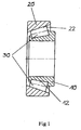
- the FIG. 1 shows as an embodiment of the invention in the form of a schematic diagram of a tapered roller bearing.
- the tapered roller bearing comprises an outer raceway element 20 and an inner raceway element 10, between which rolling elements 30 designed as truncated cones are arranged.
- the rolling elements 30 may be arranged in a cage, not shown, and between the two raceway elements 10 and 20 may be provided for sealing a rolling body 30 containing space corresponding seals.
- the rolling elements 30 are provided for rolling on in the raceway elements 10 and 20 incorporated rolling tracks 12 and 22.
- it may of course also be a multi-row roller bearing and / or cylindrical roller bearings, ball bearings, spherical roller bearings, spherical roller bearings and any other type of rolling bearing.
Landscapes
- Engineering & Computer Science (AREA)
- Chemical & Material Sciences (AREA)
- Mechanical Engineering (AREA)
- General Engineering & Computer Science (AREA)
- Physics & Mathematics (AREA)
- Thermal Sciences (AREA)
- Crystallography & Structural Chemistry (AREA)
- Materials Engineering (AREA)
- Metallurgy (AREA)
- Organic Chemistry (AREA)
- Manufacturing & Machinery (AREA)
- Rolling Contact Bearings (AREA)
Description
Die Erfindung betrifft ein Verfahren zum Herstellen eines Laufbahnelements einer Lageranordnung und ein Laufbahnelement einer Lageranordnung.The invention relates to a method for producing a raceway element of a bearing assembly and a raceway element of a bearing assembly.
Beim Einsatz von Wälzlagerungen gibt es verschiedene Schadensmechanismen, die die Lebensdauer der Wälzlagerung negativ beeinflussen können. Durch Materialermüdung an und unterhalb der Laufbahn eines Wälzlagers können aufgrund der zyklischen Beanspruchung im Hertz'schen Mikro- bzw. Makrokontakt infolge des fortwährenden Überrollens durch die Wälzkörper beispielsweise Gefügeänderungen und Risse entstehen, die in der Folge zum Ausfall des Wälzlagers führen können. Unter dem Einfluss von Mischreibung im Wälzkontakt können zudem beispielsweise spaltbruchähnliche spröde Gewaltbruchanrisse an Laufbahnoberflächen eingeleitet werden, die z. B. unter Mitwirkung von eindringendem alterndem Schmierstoff getrieben von Schwingungsrisskorrosion in die Tiefe des Werkstoffs wachsen und durch Rissrückläufer zur Oberfläche sowie Materialablösung an den Risskanten schließlich Laufbahnschälungen auslösen können. Gerade der zuletzt genannte Mechanismus der Schwingungsrisskorrosion kann zu Frühausfällen von Wälzlagern bis weit vor der nominellen L10-Lebensdauer (90% Überlebenswahrscheinlichkeit) führen. Mittels bekannter Methoden, wie beispielsweise Hartdrehen und anderer randschichtverfestigender Verfahren ist es möglich, durch Aufbau von Druckeigenspannungen an und unter der Oberfläche der Laufbahn die Bildung und Ausbreitung derartiger Risse zu behindern.When using rolling bearings, there are various damage mechanisms that can adversely affect the life of the rolling bearing. Due to the fatigue at and below the track of a rolling bearing due to the cyclic stress in the Hertzian micro or macro contact due to the continuous rolling through the rolling elements, for example, structural changes and cracks, which can lead to failure of the bearing in the sequence. In addition, under the influence of mixed friction in the rolling contact, for example, fracture-fracture-like brittle fracture fractures on raceway surfaces can be initiated, the z. B. driven by penetrating aging lubricant driven by vibration cracking corrosion in the depth of the material grow and can finally trigger cracking by crack returner to the surface and material separation at the crack edges. Especially the last mentioned mechanism of vibration crack corrosion can lead to early failures of rolling bearings well before the nominal L10 service life (90% survival probability). By means of known methods, such as hard turning and other surface layer strengthening methods, it is possible to obstruct the formation and propagation of such cracks by building up compressive stresses at and below the surface of the track.
Ein Verfahren zum Herstellen von Wälzlagerringen, bei dem Druckeigenspannungen unter die Laufbahnen eingebracht werden, ist aus
Es ist Aufgabe der vorliegenden Erfindung ein Laufbahnelement einer Wälzlageranordnung und ein Verfahren zur Herstellung des Laufbahnelements anzugeben, das gegenüber bekannten Wälzlageranordnungen eine erhöhte Lebensdauer aufweist.It is an object of the present invention to provide a raceway element of a rolling bearing assembly and a method for producing the raceway element, which has an increased service life over known roller bearing assemblies.
Diese Aufgabe wird durch ein Verfahren zur Herstellung eines Laufbahnelements einer Lageranordnung mit den Merkmalen des Hauptanspruchs bzw. durch ein Laufbahnelement einer Lageranordnung mit den Merkmalen des nebengeordneten Patentanspruchs gelöst. Vorteilhafte Ausgestaltungen der Erfindung sind Gegenstand der jeweils abhängigen Unteransprüche.This object is achieved by a method for producing a raceway element of a bearing assembly having the features of the main claim or by a raceway element of a bearing assembly having the features of the independent claim. Advantageous embodiments of the invention are the subject of the respective dependent subclaims.
Gemäß Hauptanspruch wird ein Verfahren zum Herstellen eines Laufbahnelements einer Lageranordnung, umfassend folgende Verfahrensschritte angegeben:
- Bereitstellen eines Laufbahnelements mit einer Laufbahn,
- Härten der Laufbahn durch wenigstens teilweises Aufheizen des Laufbahnelements,
- Festwalzen der Laufbahn mit einem ersten Rollkörper und
- Festwalzen der Laufbahn mit einem zweiten Rollkörper, wobei der zweite Rollkörper im Vergleich zum ersten Rollkörper wenigstens eine andere Abmessung aufweist.
- Providing a track element with a track,
- Hardening of the raceway by at least partial heating of the raceway element,
- Deep rolling the raceway with a first rolling body and
- Deep rolling the track with a second rolling body, wherein the second rolling body compared to the first rolling body has at least one other dimension.
Ein Aspekt der Erfindung beruht wesentlich auf der Erkenntnis, dass sich durch die Methode des Festwalzens mit wenigstens zwei unterschiedlich dimensionierten Rollkörpern eine besonders vorteilhafte Veränderung des Eigenspannungszustands und der Mikrostruktur an und nahe der Oberfläche des Laufbahnelements erreichen lässt. Mit dem Begriff Eigenspannungen werden hier in der üblichen Weise die Eigenspannungen 1. Art (Makroeigenspannungen) bezeichnet. Durch Festwalzen lässt sich die Ausbildung von Druckeigenspannungen unter der Oberfläche von Metallen erreichen, das Material also kaltverfestigen. Im Allgemeinen werden dabei, der Vergleichsspannung nach von Mises folgend, unmittelbar an der Oberfläche Druckeigenspannungen zu einem gewissen Grad aufgebaut, der sich mit zunehmender Tiefe bis zu einem Maximalwert intensiviert. Mit weiter zunehmender Tiefe nimmt der Betrag der Druckeigenspannung dann wieder ab. Typischerweise können in gehärteten Stählen Druckeigenspannungen in signifikanter Größe bis zu einem Tiefenbereich von mehreren 100 µm erzeugt werden. Bei bekannten Verfahren des Festwalzens besteht jedoch eine vergleichsweise große Differenz zwischen dem betraglichen Maximalwert der Druckeigenspannungen und dem Betrag der Druckeigenspannungen an der Oberfläche bzw. in geringer Tiefe von ungefähr 10 µm bzw. wenigen 10 µm. Bis zum Maximalwert der Druckeigenspannung am Ort der höchsten von Mises-Vergleichsspannung für den Hertz'schen (Makro-) Kontakt mit dem Rollkörper fällt der Betrag der Druckeigenspannungen zur Oberfläche hin somit vergleichsweise stark ab. Um beim Festwalzen sowohl an und sehr nahe der Oberfläche bis in eine typische Tiefe von mehreren 10 µm als auch in größerer Tiefe von typischerweise mehreren 100 µm einen ausreichenden Betrag an Druckeigenspannungen aufzubauen, ist es vorteilhaft möglich, mit Rollkörpern unterschiedlichen Durchmessers zu arbeiten. Durch das abwechselnde Festwalzen der Laufbahn mit zwei oder mehr unterschiedlich großen Rollkörpern lässt sich gezielt eine optimale Eigenspannungsverteilung zwischen der Oberfläche und den Maxima bzw. dem zusammenwachsenden Maximum der Druckeigenspannungen einstellen, wodurch bereits in geringeren Tiefen bis beispielsweise 100 µm eine dem Maximalwert ausreichend angenäherte Druckeigenspannung erzeugt werden kann. Plastifizierung und Druckeigenspannungsaufbau hängen nämlich maßgeblich mit der Geometrie des beim Festwalzen verwendeten Rollkörpers zusammen. Neben dem Druckeigenspannungsaufbau führt Versetzungsgleiten während der plastischen Verformung zur Ausbildung energetisch günstiger Versetzungsanordnungen (z. B. Versetzungsmultipole), was die Mikrostruktur des Werkstoffs stabilisiert.One aspect of the invention is based essentially on the finding that a particularly advantageous change in the residual stress state and the microstructure at and near the surface of the raceway element can be achieved by the method of deep rolling with at least two differently dimensioned rolling bodies. The term residual stresses here refers to the residual stresses of the first kind (macro-tensions) in the usual way. By deep rolling, the formation of residual compressive stresses can be achieved below the surface of metals, so cold work the material. Generally, according to the comparative stress of Mises, compressive stresses are built up to a certain extent directly at the surface, which intensifies with increasing depth up to a maximum value. With further increasing depth of the amount of residual compressive stress then decreases again. Typically, in tempered steels, compressive stresses of significant magnitude can be generated up to a depth range of several hundred microns. In known methods of deep rolling, however, there is a comparatively large difference between the maximum amount the compressive residual stresses and the amount of residual compressive stresses at the surface or at a shallow depth of about 10 microns or a few 10 microns. Up to the maximum value of the compressive residual stress at the location of the highest von Mises reference stress for the Hertzian (macro) contact with the rolling body, the amount of residual compressive stresses thus decreases comparatively strongly towards the surface. In order to build up a sufficient amount of compressive residual stresses during deep rolling both at and very close to the surface to a typical depth of several 10 μm as well as at a greater depth of typically several 100 μm, it is advantageously possible to work with rolling bodies of different diameters. By alternately deep rolling the track with two or more different sized rolling bodies can be targeted set an optimum residual stress distribution between the surface and the maxima or the growing maximum of compressive residual stresses, which produces a low enough to maximum, for example, 100 microns, the maximum value approximate compressive residual stress can be. Plastification and compressive stress build-up are significantly related to the geometry of the rolling body used in deep rolling. In addition to compressive residual stress, dislocation sliding during plastic deformation leads to the formation of energetically favorable dislocation arrangements (eg, dislocation multipoles), which stabilizes the microstructure of the material.
In einer bevorzugten Ausführungsform der Erfindung weisen beide Rollkörper eine kugeloder zylinderartige Form und unterschiedliche Durchmesser auf. Alternativ sind auch gemischte Verwendungen von Zylindern oder kugelartigen Rollkörpern mit unterschiedlichen Durchmessern möglich.In a preferred embodiment of the invention, both rolling bodies have a spherical or cylindrical shape and different diameters. Alternatively, mixed uses of cylinders or spherical rolling bodies with different diameters are possible.
Vorteilhafterweise lässt sich nach dem Festwalzen mit dem zweiten Rollkörper ein materialabtragender Verfahrensschritt einführen, bei dem die Oberfläche des Laufbahnelements im Bereich der Laufbahn teilweise entfernt wird. Dies ist insbesondere dann von Vorteil, wenn durch den Festwalzschritt die Oberflächenrauhigkeit derart erhöht wurde, dass die Qualität für einen guten Lagerbetrieb im Wälzkontakt nicht mehr ausreichend ist. Dabei ist insbesondere ein Hon- oder schonender Schleifvorgang vorteilhaft, beispielsweise Gleitschleifen, bei dem weniger als 50 µm Material von der Oberfläche entfernt werden, um den Tiefenbereich der aufgebauten Druckeigenspannungen weitgehend zu erhalten. Vorteilhaft ist ebenfalls, eine abschließende thermische Nachbehandlung zumindest der Laufbahn des Laufbahnelements bei einer Temperatur, die kleiner als die Anlass- oder Umwandlungstemperatur beim martensitischen bzw. bainitischen Härten ist. Dieses Nacherwärmen dient der beispielsweise durch die Abnahme der röntgenografischen Linienbreite nachweisbaren Stabilisierung der Mikrostruktur des Werkstoffs in der mechanisch beeinflussten Randschicht und kann an Luft oder in chemisch inerter Umgebung (z. B. Vakuum, Schutzgas, Salzbad) erfolgen. Durch den gewählten Temperaturbereich wird bei typischer Dauer der thermischen Nachbehandlung von etwa 1 Stunde einem Verlust an Härte entgegengewirkt.Advantageously, after the deep rolling with the second rolling body, a material-removing process step can be introduced in which the surface of the raceway element in the region of the raceway is partially removed. This is particularly advantageous if the surface roughness was increased by the deep rolling step such that the quality is no longer sufficient for good bearing operation in rolling contact. In particular, a honing or gentle grinding process is advantageous, for example vibratory grinding, in which less than 50 μm of material is removed from the surface in order to largely preserve the depth range of the built-up residual compressive stresses. It is also advantageous, a final thermal treatment of at least the career of the raceway element at a temperature which is less than the tempering or transformation temperature during martensitic or bainitic hardening. This reheating serves to stabilize the microstructure of the material in the mechanically influenced boundary layer that can be detected, for example, by decreasing the X-ray line width and can take place in air or in a chemically inert environment (eg vacuum, inert gas, salt bath). Due to the selected temperature range, a loss of hardness is counteracted during a typical duration of the thermal aftertreatment of about 1 hour.
Weitere Vorteile und Ausgestaltungen der Erfindung ergeben sich aus dem im Folgenden beschriebenen Ausführungsbeispiel der Erfindung anhand der beigefügten Figuren. Es zeigen:
- Figur 1
- eine Kegelrollenlageranordnung und
- Figur 2
- ein schematisches Diagramm eines typischen Druckeigenspannungsverlaufs eines Laufbahnelements des Kegelrollenlagers der
Figur 1 .
- FIG. 1
- a tapered roller bearing assembly and
- FIG. 2
- a schematic diagram of a typical compressive residual stress profile of a raceway element of the tapered roller bearing of the
FIG. 1 ,
Das erfindungsgemäße Laufbahnelement lässt sich insbesondere bei hoch belasteten Kegelrollen- bzw. Zylinderrollenlageranordnungen einsetzen, wie sie beispielsweise in Windkraftanwendungen, anderen Industriegetrieben oder Schiffsantrieben eingesetzt werden. Die
In Ausführungsbeispielen der Erfindung ist es vorteilhaft, den Verlauf der Druckeigenspannungen von der Oberfläche bis in den Bereich des Druckeigenspannungsmaximums in der Tiefe gleichmäßiger auszugestalten, als dies mit bekannten Verfahren wie Kugelstrahlen, Hartdrehen oder herkömmlichen Festwalzprozessen möglich ist. Dies wird insbesondere dadurch erreicht, dass nach dem Härten der Laufbahn des Laufbahnelements zwei Festwalzschritte mit unterschiedlichen Rollkörpern durchgeführt werden. Dabei wird beispielsweise mit zwei Keramik- oder Hartmetallkugeln unterschiedlichen Durchmessers nacheinander über die Laufbahn gewalzt, wodurch Druckeigenspannungen erzeugt werden. In Abhängigkeit von der Geometrie der Rollkörper bauen sich die Druckeigenspannungen bevorzugt in verschiedenen Tiefen auf Das Tiefenprofil folgt dabei der Verteilung der von Mises-Vergleichsspannung, wobei mit wiederholten Überrollungen eine Überlagerung mit den bereits erzeugten Druckeigenspannungen stattfindet. Insgesamt ergibt sich durch die zwei oder mehr separaten Festwalzprozesse ein überlagerter Druckeigenspannungsverlauf, bei dem bereits in geringer Tiefe eine vergleichsweise nahe dem maximalen Betrag liegende Druckeigenspannung auftritt. Im Gegensatz dazu fällt der Betrag der Druckeigenspannung beim Kugelstrahlen, Festwalzen mit nur einem Wälzkörper oder Hartdrehen in geringer Tiefe vergleichsweise stärker ab. Dieser starke Abfall innerhalb geringer Tiefe bis beispielsweise 50 µm oder 100 µm je nach angewendetem Verfahren wirkt sich insbesondere bei oberflächeninduzierter normalspannungsgesteuerter Rissbildung (z. B. durch Reibzugspannungen) nachteilig auf die Lebensdauer des Laufbahnelements aus. Durch das Festwalzen der Laufbahn mit zwei unterschiedlich großen Rollkörpern lässt sich der Verlauf der Druckeigenspannungen bis zum Maximalwert dem idealen Verlauf einer konstanten Druckeigenspannung mit zunehmender Tiefe im Vergleich zu bekannten Verfahren besser annähern.In embodiments of the invention, it is advantageous to design the course of the residual compressive stresses from the surface to the region of the compressive residual stress maximum in the depth more uniformly than is possible with known methods such as shot peening, hard turning or conventional deep-rolling processes. This is achieved in particular by carrying out two hard rolling steps with different rolling bodies after the curing of the track of the track element. In this case, for example, with two ceramic or hard metal balls of different diameters rolled successively over the track, whereby residual compressive stresses are generated. Depending on the geometry of the rolling bodies, the compressive stresses tend to build up at different depths. The depth profile follows the distribution of the von Mises reference stress, with repeated overrolling taking place with the already generated residual compressive stresses. Overall, results from the two or more separate deep rolling processes superimposed pressure residual stress curve, in which even at a shallow depth, a relatively close to the maximum amount of compressive residual stress occurs. In contrast, the amount of compressive residual stress during shot peening, deep rolling with only one rolling element or hard turning at a shallow depth drops relatively more. This large drop within a shallow depth of up to, for example, 50 μm or 100 μm, depending on the method used, has a disadvantageous effect on the service life of the raceway element, in particular in the case of surface-induced normal stress-controlled crack formation (for example due to friction tensile stresses). Due to the deep rolling of the raceway with two different sized rolling bodies, the course of the compressive residual stresses up to the maximum value can better approximate the ideal course of a constant compressive residual stress with increasing depth in comparison to known methods.
Das Laufbahnelement der Wälzlageranordnung weist bevorzugt unter der Oberfläche der Laufbahn bis zu einer Tiefe von wenigstens 200 µm Druckeigenspannungen von mindestens 400 MPa auf. Bevorzugt liegt das Maximum der Druckeigenspannung jedoch zwischen 500 MPa und 800 MPa bis möglichst nicht wesentlich über 1000 MPa. Bis zu einer Tiefe von 100 µm jedoch liegen die Druckeigenspannungen mindestens bei einem Wert von 40% des Maximalwerts der Druckeigenspannung. Dadurch lässt sich ein mit zunehmender Tiefe gleichmäßigerer Eigenspannungszustand als bei bekannten Verfahren des Randschicht- bzw. Kaltverfestigens erreichen. Dies wiederum resultiert in einer erhöhten Lebensdauer des Laufbahnelements und somit der Wälzlageranordnung unter den genannten Betriebs- bzw. Beanspruchungsbedingungen. In der
Vorteilhaft ist die Verwendung von kugel- und/oder walzenartigen Rollkörpern, wobei allerdings auch andere Geometrien zum Einsatz kommen können. Zudem können die beiden Walzschritte auch mit Rollkörpern unterschiedlicher Grundform erfolgen. Bevorzugt liegen bei zylindrischen Rollkörpern der Durchmesser des kleineren Rollkörpers zwischen 1 und 3 mm und der Durchmesser des größeren Rollkörpers zwischen 6 und 9 mm, besonders vorteilhaft 7 und 8 mm.Advantageous is the use of ball and / or roller-like rolling bodies, although other geometries can be used. In addition, the two rolling steps can also be done with rolling bodies of different basic shape. In cylindrical rolling bodies, the diameter of the smaller rolling body is preferably between 1 and 3 mm and the diameter of the larger rolling body is between 6 and 9 mm, particularly advantageously 7 and 8 mm.
Verfahren nach Ausführungsbeispielen der Erfindung lassen sich vorteilhaft bei allen bekannten Lagertypen, also neben Kegelrollen- insbesondere auch bei Zylinder-, Kugel- und Pendelrollenlagern einsetzen, wobei die Anforderungen an den Verlauf der Druckeigenspannungen je nach Einsatzbereich des Wälzlagers unterschiedlich ausfallen können. Es lassen sich jedoch deutlich gezielter anforderungsgerechte Verläufe erzeugen als bei bekannten Verfahren.Processes according to embodiments of the invention can be used advantageously in all known types of bearings, ie in addition to tapered roller, especially in cylindrical, spherical and spherical roller bearings, the requirements for the course of compressive residual stresses can vary depending on the application of the bearing. However, it is possible to produce processes that are more specifically tailored to requirements than in the case of known methods.
- 10, 2010, 20
- LaufbahnelementTrack element
- 12, 2212, 22
- Abrollbahnrolling path
- 3030
- Wälzkörperrolling elements
Claims (8)
- Method for manufacturing a raceway element of a bearing assembly, said method comprising the following method steps:- providing a raceway element having a raceway,- hardening the raceway by at least partially heating the raceway element, deep rolling the raceway with a first rolling element, and- deep rolling the raceway with a second rolling element, the second rolling element having at least one different dimension as compared to the first rolling element.
- Method according to Claim 1, wherein at least one of the rolling elements has a spherical form.
- Method according to Claim 1, wherein both rolling elements have a spherical or cylindrical shape and have different diameters.
- Method according to one of Claims 1 to 3, wherein, after the deep rolling with the second rolling element, a material-removing method step is carried out, in which the surface of the raceway element is partially removed in the region of the raceway.
- Method according to Claim 4, wherein less than 50 µm of the surface are removed during the material-removing method step.
- Method according to Claim 4 or 5, wherein a thermal post-treatment is carried out after the deep rolling, a honing process or a grinding process.
- Method according to Claim 6, wherein the thermal post-treatment is carried out at a temperature which is lower than the annealing or transformation temperature of the hardening step.
- Raceway element of a rolling bearing assembly, said element comprising the following features:- at least one raceway, on which rolling bodies of the rolling bearing assembly are intended to roll,- residual compressive stresses of at least 400 MPa are formed beneath the surface of the raceway down to a depth of at least 200 µm, the minimum of the residual compressive stress being between 400 and 500 MPa and the maximum of the residual compressive stress being between 500 and 800 MPa; and- the magnitude of the residual compressive stresses changes by at most 500 MPa down to a depth of 100 µm.
Applications Claiming Priority (2)
| Application Number | Priority Date | Filing Date | Title |
|---|---|---|---|
| DE102011085205.0A DE102011085205B4 (en) | 2011-10-26 | 2011-10-26 | Method for producing a raceway element of a bearing arrangement and raceway element |
| PCT/EP2012/071167 WO2013060783A1 (en) | 2011-10-26 | 2012-10-25 | Method for producing a track element of a bearing assembly, and track element |
Publications (2)
| Publication Number | Publication Date |
|---|---|
| EP2771585A1 EP2771585A1 (en) | 2014-09-03 |
| EP2771585B1 true EP2771585B1 (en) | 2016-02-24 |
Family
ID=47178594
Family Applications (1)
| Application Number | Title | Priority Date | Filing Date |
|---|---|---|---|
| EP12786867.7A Active EP2771585B1 (en) | 2011-10-26 | 2012-10-25 | Method of manufacture a raceway element of a bearing arrangement and raceway element |
Country Status (6)
| Country | Link |
|---|---|
| US (1) | US9273727B2 (en) |
| EP (1) | EP2771585B1 (en) |
| JP (1) | JP2014531010A (en) |
| CN (1) | CN104011413B (en) |
| DE (1) | DE102011085205B4 (en) |
| WO (1) | WO2013060783A1 (en) |
Cited By (2)
| Publication number | Priority date | Publication date | Assignee | Title |
|---|---|---|---|---|
| DE102016114895A1 (en) * | 2016-08-11 | 2018-02-15 | Thyssenkrupp Ag | Method for hardening a rolling body raceway of a rolling bearing ring and rolling bearing ring |
| DE102019218794A1 (en) * | 2019-12-03 | 2021-06-10 | Thyssenkrupp Ag | Process for increasing the load-bearing capacity and rolling device for hard rolling a surface-hardened roller bearing raceway |
Families Citing this family (6)
| Publication number | Priority date | Publication date | Assignee | Title |
|---|---|---|---|---|
| DE102015207779A1 (en) * | 2015-04-28 | 2016-11-03 | Schaeffler Technologies AG & Co. KG | Method for producing rolling bearing rings and roller bearings |
| CN106346193A (en) * | 2016-11-17 | 2017-01-25 | 中车洛阳机车有限公司 | Arc rolling strengthening device |
| US10365107B2 (en) * | 2017-08-03 | 2019-07-30 | Honeywell International Inc. | Systems and methods for reducing polarization-related bias errors in RFOGS |
| DE102017121629A1 (en) * | 2017-09-19 | 2019-03-21 | Schaeffler Technologies AG & Co. KG | Method for producing a bearing component and bearing component |
| US11338980B2 (en) | 2018-07-20 | 2022-05-24 | The Procter & Gamble Company | Shaped flexible shipping package and method of making |
| DE102019127123B4 (en) * | 2019-10-09 | 2023-03-16 | Schaeffler Technologies AG & Co. KG | Process and device for machining a rolling bearing component |
Family Cites Families (12)
| Publication number | Priority date | Publication date | Assignee | Title |
|---|---|---|---|---|
| DE854607C (en) * | 1940-05-11 | 1952-11-06 | Charles Antony Ablett | Rolling bearing with an inner and / or outer race that is divided into two or more parts |
| DE3037688C2 (en) * | 1980-10-06 | 1982-12-02 | Wilhelm Hegenscheidt, Gmbh, 5140 Erkelenz | Process for deep rolling crankshafts |
| EP0215179B1 (en) * | 1985-08-30 | 1991-08-28 | Wilhelm Hegenscheidt Gesellschaft mbH | Burnishing device |
| JP3593668B2 (en) * | 1994-06-21 | 2004-11-24 | Ntn株式会社 | Rolling bearing |
| DE10209264B4 (en) * | 2002-03-01 | 2005-06-02 | Ab Skf | Method for producing a metal component |
| KR20050004843A (en) | 2002-05-14 | 2005-01-12 | 고요 세이코 가부시키가이샤 | Method of producing bearing raceway member |
| DE102004041964B4 (en) * | 2004-08-04 | 2012-04-26 | Schaeffler Technologies Gmbh & Co. Kg | Machine element for rolling load |
| JP2006329319A (en) * | 2005-05-26 | 2006-12-07 | Jtekt Corp | Rolling/sliding component, rolling bearing, cam follower, and surface improving method for rolling/sliding component |
| ES2318687T3 (en) * | 2006-10-23 | 2009-05-01 | Cornelius Reuss | PROCEDURE AND DEVICE FOR HARNESSING CRANKSHAFT. |
| DE102006055027A1 (en) * | 2006-11-22 | 2008-05-29 | Schaeffler Kg | Radial rolling bearings, in particular for the storage of shafts in wind power transmissions |
| DE102007055575B4 (en) * | 2007-11-20 | 2016-06-09 | Ab Skf | Raceway element of a roller bearing |
| DE112009000609T5 (en) * | 2008-03-13 | 2011-01-13 | NTN Corporation, Osaka-shi | Method for producing an outer ring, outer ring for double-row angular contact bearing, double-row angular contact bearing and bearing device for wheels |
-
2011
- 2011-10-26 DE DE102011085205.0A patent/DE102011085205B4/en not_active Expired - Fee Related
-
2012
- 2012-10-25 EP EP12786867.7A patent/EP2771585B1/en active Active
- 2012-10-25 CN CN201280064446.XA patent/CN104011413B/en active Active
- 2012-10-25 US US14/354,178 patent/US9273727B2/en active Active
- 2012-10-25 JP JP2014537617A patent/JP2014531010A/en not_active Withdrawn
- 2012-10-25 WO PCT/EP2012/071167 patent/WO2013060783A1/en active Application Filing
Cited By (2)
| Publication number | Priority date | Publication date | Assignee | Title |
|---|---|---|---|---|
| DE102016114895A1 (en) * | 2016-08-11 | 2018-02-15 | Thyssenkrupp Ag | Method for hardening a rolling body raceway of a rolling bearing ring and rolling bearing ring |
| DE102019218794A1 (en) * | 2019-12-03 | 2021-06-10 | Thyssenkrupp Ag | Process for increasing the load-bearing capacity and rolling device for hard rolling a surface-hardened roller bearing raceway |
Also Published As
| Publication number | Publication date |
|---|---|
| DE102011085205B4 (en) | 2016-09-22 |
| CN104011413B (en) | 2018-05-01 |
| US20150036960A1 (en) | 2015-02-05 |
| EP2771585A1 (en) | 2014-09-03 |
| CN104011413A (en) | 2014-08-27 |
| WO2013060783A1 (en) | 2013-05-02 |
| JP2014531010A (en) | 2014-11-20 |
| US9273727B2 (en) | 2016-03-01 |
| DE102011085205A1 (en) | 2013-05-02 |
Similar Documents
| Publication | Publication Date | Title |
|---|---|---|
| EP2771585B1 (en) | Method of manufacture a raceway element of a bearing arrangement and raceway element | |
| EP2759729B1 (en) | Method for manufacturing a roller bearing and roller bearing | |
| DE102007055575B4 (en) | Raceway element of a roller bearing | |
| DE102012204409B3 (en) | Method for producing a rolling bearing and rolling bearing | |
| DE10016316B4 (en) | Rolling bearing and method for its production | |
| WO2008061507A1 (en) | Radial roller bearing, in particular for storing shafts in wind turbine transmissions | |
| EP1774188B1 (en) | Hybrid roller bearing | |
| DE102005060113B4 (en) | Wheel bearing and method for producing the same | |
| DE69228730T2 (en) | Inventory components and processes for their manufacture | |
| DE10080396B4 (en) | Process for producing rolling elements and rolling bearing manufactured according to this method | |
| DE112011103863T5 (en) | Double row bearing assembly | |
| EP2094983B1 (en) | Radial roller bearing, in particular for storing shafts in wind turbine transmissions | |
| DE112015005630T5 (en) | Bearing component and method | |
| DE112019001585T5 (en) | Tapered roller bearings | |
| DE102015201644B4 (en) | Method for deep rolling a metallic object, in particular a raceway of a roller bearing | |
| EP3289235B1 (en) | Method for manufacturing a bearing raceway ring and rolling element bearing | |
| DE102018206635A1 (en) | Hybrid rolling bearing, in particular for a refrigerating compressor | |
| EP3228889B1 (en) | Track element for a large-diameter rolling bearing and bearing assembly | |
| DE102018221175A1 (en) | Hybrid roller bearings, in particular for a refrigerant compressor | |
| EP3538678B1 (en) | Method for producing a rolling bearing ring having an improved robustness against the formation of white etching cracks (wec) | |
| DE10147926B4 (en) | roller bearing | |
| EP2828540A1 (en) | Method for producing a rolling bearing, and rolling bearing | |
| Beer | Nitriding of rolling contact races | |
| WO2008061508A1 (en) | Radial roller bearing, in particular for storing shafts in wind turbine transmissions | |
| DE102019127123B4 (en) | Process and device for machining a rolling bearing component |
Legal Events
| Date | Code | Title | Description |
|---|---|---|---|
| PUAI | Public reference made under article 153(3) epc to a published international application that has entered the european phase |
Free format text: ORIGINAL CODE: 0009012 |
|
| 17P | Request for examination filed |
Effective date: 20140411 |
|
| AK | Designated contracting states |
Kind code of ref document: A1 Designated state(s): AL AT BE BG CH CY CZ DE DK EE ES FI FR GB GR HR HU IE IS IT LI LT LU LV MC MK MT NL NO PL PT RO RS SE SI SK SM TR |
|
| DAX | Request for extension of the european patent (deleted) | ||
| GRAP | Despatch of communication of intention to grant a patent |
Free format text: ORIGINAL CODE: EPIDOSNIGR1 |
|
| RIC1 | Information provided on ipc code assigned before grant |
Ipc: C21D 1/02 20060101ALI20150521BHEP Ipc: B23P 15/00 20060101ALI20150521BHEP Ipc: F16C 19/24 20060101ALI20150521BHEP Ipc: F16C 33/64 20060101AFI20150521BHEP Ipc: F16C 33/58 20060101ALI20150521BHEP Ipc: C21D 9/40 20060101ALI20150521BHEP |
|
| RIC1 | Information provided on ipc code assigned before grant |
Ipc: C21D 1/02 20060101ALI20150529BHEP Ipc: C21D 9/40 20060101ALI20150529BHEP Ipc: B23P 15/00 20060101ALI20150529BHEP Ipc: F16C 19/36 20060101ALN20150529BHEP Ipc: F16C 33/58 20060101ALI20150529BHEP Ipc: F16C 33/64 20060101AFI20150529BHEP |
|
| INTG | Intention to grant announced |
Effective date: 20150617 |
|
| GRAP | Despatch of communication of intention to grant a patent |
Free format text: ORIGINAL CODE: EPIDOSNIGR1 |
|
| RIC1 | Information provided on ipc code assigned before grant |
Ipc: B23P 15/00 20060101ALI20150811BHEP Ipc: C21D 1/02 20060101ALI20150811BHEP Ipc: C21D 9/40 20060101ALI20150811BHEP Ipc: F16C 19/36 20060101ALN20150811BHEP Ipc: F16C 33/58 20060101ALI20150811BHEP Ipc: F16C 33/64 20060101AFI20150811BHEP |
|
| INTG | Intention to grant announced |
Effective date: 20150917 |
|
| GRAS | Grant fee paid |
Free format text: ORIGINAL CODE: EPIDOSNIGR3 |
|
| GRAA | (expected) grant |
Free format text: ORIGINAL CODE: 0009210 |
|
| AK | Designated contracting states |
Kind code of ref document: B1 Designated state(s): AL AT BE BG CH CY CZ DE DK EE ES FI FR GB GR HR HU IE IS IT LI LT LU LV MC MK MT NL NO PL PT RO RS SE SI SK SM TR |
|
| REG | Reference to a national code |
Ref country code: GB Ref legal event code: FG4D Free format text: NOT ENGLISH |
|
| REG | Reference to a national code |
Ref country code: CH Ref legal event code: EP |
|
| REG | Reference to a national code |
Ref country code: AT Ref legal event code: REF Ref document number: 776894 Country of ref document: AT Kind code of ref document: T Effective date: 20160315 |
|
| REG | Reference to a national code |
Ref country code: IE Ref legal event code: FG4D Free format text: LANGUAGE OF EP DOCUMENT: GERMAN |
|
| REG | Reference to a national code |
Ref country code: DE Ref legal event code: R096 Ref document number: 502012006075 Country of ref document: DE |
|
| REG | Reference to a national code |
Ref country code: LT Ref legal event code: MG4D |
|
| REG | Reference to a national code |
Ref country code: NL Ref legal event code: MP Effective date: 20160224 |
|
| PG25 | Lapsed in a contracting state [announced via postgrant information from national office to epo] |
Ref country code: FI Free format text: LAPSE BECAUSE OF FAILURE TO SUBMIT A TRANSLATION OF THE DESCRIPTION OR TO PAY THE FEE WITHIN THE PRESCRIBED TIME-LIMIT Effective date: 20160224 Ref country code: IT Free format text: LAPSE BECAUSE OF FAILURE TO SUBMIT A TRANSLATION OF THE DESCRIPTION OR TO PAY THE FEE WITHIN THE PRESCRIBED TIME-LIMIT Effective date: 20160224 Ref country code: ES Free format text: LAPSE BECAUSE OF FAILURE TO SUBMIT A TRANSLATION OF THE DESCRIPTION OR TO PAY THE FEE WITHIN THE PRESCRIBED TIME-LIMIT Effective date: 20160224 Ref country code: GR Free format text: LAPSE BECAUSE OF FAILURE TO SUBMIT A TRANSLATION OF THE DESCRIPTION OR TO PAY THE FEE WITHIN THE PRESCRIBED TIME-LIMIT Effective date: 20160525 Ref country code: NO Free format text: LAPSE BECAUSE OF FAILURE TO SUBMIT A TRANSLATION OF THE DESCRIPTION OR TO PAY THE FEE WITHIN THE PRESCRIBED TIME-LIMIT Effective date: 20160524 Ref country code: HR Free format text: LAPSE BECAUSE OF FAILURE TO SUBMIT A TRANSLATION OF THE DESCRIPTION OR TO PAY THE FEE WITHIN THE PRESCRIBED TIME-LIMIT Effective date: 20160224 |
|
| PG25 | Lapsed in a contracting state [announced via postgrant information from national office to epo] |
Ref country code: PL Free format text: LAPSE BECAUSE OF FAILURE TO SUBMIT A TRANSLATION OF THE DESCRIPTION OR TO PAY THE FEE WITHIN THE PRESCRIBED TIME-LIMIT Effective date: 20160224 Ref country code: RS Free format text: LAPSE BECAUSE OF FAILURE TO SUBMIT A TRANSLATION OF THE DESCRIPTION OR TO PAY THE FEE WITHIN THE PRESCRIBED TIME-LIMIT Effective date: 20160224 Ref country code: PT Free format text: LAPSE BECAUSE OF FAILURE TO SUBMIT A TRANSLATION OF THE DESCRIPTION OR TO PAY THE FEE WITHIN THE PRESCRIBED TIME-LIMIT Effective date: 20160624 Ref country code: LV Free format text: LAPSE BECAUSE OF FAILURE TO SUBMIT A TRANSLATION OF THE DESCRIPTION OR TO PAY THE FEE WITHIN THE PRESCRIBED TIME-LIMIT Effective date: 20160224 Ref country code: SE Free format text: LAPSE BECAUSE OF FAILURE TO SUBMIT A TRANSLATION OF THE DESCRIPTION OR TO PAY THE FEE WITHIN THE PRESCRIBED TIME-LIMIT Effective date: 20160224 Ref country code: LT Free format text: LAPSE BECAUSE OF FAILURE TO SUBMIT A TRANSLATION OF THE DESCRIPTION OR TO PAY THE FEE WITHIN THE PRESCRIBED TIME-LIMIT Effective date: 20160224 Ref country code: NL Free format text: LAPSE BECAUSE OF FAILURE TO SUBMIT A TRANSLATION OF THE DESCRIPTION OR TO PAY THE FEE WITHIN THE PRESCRIBED TIME-LIMIT Effective date: 20160224 |
|
| PG25 | Lapsed in a contracting state [announced via postgrant information from national office to epo] |
Ref country code: EE Free format text: LAPSE BECAUSE OF FAILURE TO SUBMIT A TRANSLATION OF THE DESCRIPTION OR TO PAY THE FEE WITHIN THE PRESCRIBED TIME-LIMIT Effective date: 20160224 Ref country code: DK Free format text: LAPSE BECAUSE OF FAILURE TO SUBMIT A TRANSLATION OF THE DESCRIPTION OR TO PAY THE FEE WITHIN THE PRESCRIBED TIME-LIMIT Effective date: 20160224 |
|
| REG | Reference to a national code |
Ref country code: DE Ref legal event code: R097 Ref document number: 502012006075 Country of ref document: DE |
|
| PG25 | Lapsed in a contracting state [announced via postgrant information from national office to epo] |
Ref country code: SM Free format text: LAPSE BECAUSE OF FAILURE TO SUBMIT A TRANSLATION OF THE DESCRIPTION OR TO PAY THE FEE WITHIN THE PRESCRIBED TIME-LIMIT Effective date: 20160224 Ref country code: SK Free format text: LAPSE BECAUSE OF FAILURE TO SUBMIT A TRANSLATION OF THE DESCRIPTION OR TO PAY THE FEE WITHIN THE PRESCRIBED TIME-LIMIT Effective date: 20160224 Ref country code: CZ Free format text: LAPSE BECAUSE OF FAILURE TO SUBMIT A TRANSLATION OF THE DESCRIPTION OR TO PAY THE FEE WITHIN THE PRESCRIBED TIME-LIMIT Effective date: 20160224 Ref country code: RO Free format text: LAPSE BECAUSE OF FAILURE TO SUBMIT A TRANSLATION OF THE DESCRIPTION OR TO PAY THE FEE WITHIN THE PRESCRIBED TIME-LIMIT Effective date: 20160224 |
|
| PLBE | No opposition filed within time limit |
Free format text: ORIGINAL CODE: 0009261 |
|
| STAA | Information on the status of an ep patent application or granted ep patent |
Free format text: STATUS: NO OPPOSITION FILED WITHIN TIME LIMIT |
|
| 26N | No opposition filed |
Effective date: 20161125 |
|
| PG25 | Lapsed in a contracting state [announced via postgrant information from national office to epo] |
Ref country code: BG Free format text: LAPSE BECAUSE OF FAILURE TO SUBMIT A TRANSLATION OF THE DESCRIPTION OR TO PAY THE FEE WITHIN THE PRESCRIBED TIME-LIMIT Effective date: 20160524 Ref country code: SI Free format text: LAPSE BECAUSE OF FAILURE TO SUBMIT A TRANSLATION OF THE DESCRIPTION OR TO PAY THE FEE WITHIN THE PRESCRIBED TIME-LIMIT Effective date: 20160224 Ref country code: BE Free format text: LAPSE BECAUSE OF NON-PAYMENT OF DUE FEES Effective date: 20161031 |
|
| REG | Reference to a national code |
Ref country code: CH Ref legal event code: PL |
|
| GBPC | Gb: european patent ceased through non-payment of renewal fee |
Effective date: 20161025 |
|
| REG | Reference to a national code |
Ref country code: IE Ref legal event code: MM4A |
|
| REG | Reference to a national code |
Ref country code: FR Ref legal event code: ST Effective date: 20170630 |
|
| PG25 | Lapsed in a contracting state [announced via postgrant information from national office to epo] |
Ref country code: GB Free format text: LAPSE BECAUSE OF NON-PAYMENT OF DUE FEES Effective date: 20161025 Ref country code: CH Free format text: LAPSE BECAUSE OF NON-PAYMENT OF DUE FEES Effective date: 20161031 Ref country code: LI Free format text: LAPSE BECAUSE OF NON-PAYMENT OF DUE FEES Effective date: 20161031 Ref country code: FR Free format text: LAPSE BECAUSE OF NON-PAYMENT OF DUE FEES Effective date: 20161102 |
|
| PG25 | Lapsed in a contracting state [announced via postgrant information from national office to epo] |
Ref country code: LU Free format text: LAPSE BECAUSE OF NON-PAYMENT OF DUE FEES Effective date: 20161025 |
|
| PG25 | Lapsed in a contracting state [announced via postgrant information from national office to epo] |
Ref country code: IE Free format text: LAPSE BECAUSE OF NON-PAYMENT OF DUE FEES Effective date: 20161025 |
|
| REG | Reference to a national code |
Ref country code: BE Ref legal event code: MM Effective date: 20161031 |
|
| PG25 | Lapsed in a contracting state [announced via postgrant information from national office to epo] |
Ref country code: HU Free format text: LAPSE BECAUSE OF FAILURE TO SUBMIT A TRANSLATION OF THE DESCRIPTION OR TO PAY THE FEE WITHIN THE PRESCRIBED TIME-LIMIT; INVALID AB INITIO Effective date: 20121025 |
|
| PG25 | Lapsed in a contracting state [announced via postgrant information from national office to epo] |
Ref country code: MK Free format text: LAPSE BECAUSE OF FAILURE TO SUBMIT A TRANSLATION OF THE DESCRIPTION OR TO PAY THE FEE WITHIN THE PRESCRIBED TIME-LIMIT Effective date: 20160224 Ref country code: IS Free format text: LAPSE BECAUSE OF FAILURE TO SUBMIT A TRANSLATION OF THE DESCRIPTION OR TO PAY THE FEE WITHIN THE PRESCRIBED TIME-LIMIT Effective date: 20160224 Ref country code: MC Free format text: LAPSE BECAUSE OF FAILURE TO SUBMIT A TRANSLATION OF THE DESCRIPTION OR TO PAY THE FEE WITHIN THE PRESCRIBED TIME-LIMIT Effective date: 20160224 Ref country code: MT Free format text: LAPSE BECAUSE OF FAILURE TO SUBMIT A TRANSLATION OF THE DESCRIPTION OR TO PAY THE FEE WITHIN THE PRESCRIBED TIME-LIMIT Effective date: 20160224 Ref country code: CY Free format text: LAPSE BECAUSE OF FAILURE TO SUBMIT A TRANSLATION OF THE DESCRIPTION OR TO PAY THE FEE WITHIN THE PRESCRIBED TIME-LIMIT Effective date: 20160224 |
|
| PG25 | Lapsed in a contracting state [announced via postgrant information from national office to epo] |
Ref country code: TR Free format text: LAPSE BECAUSE OF FAILURE TO SUBMIT A TRANSLATION OF THE DESCRIPTION OR TO PAY THE FEE WITHIN THE PRESCRIBED TIME-LIMIT Effective date: 20160224 Ref country code: AL Free format text: LAPSE BECAUSE OF FAILURE TO SUBMIT A TRANSLATION OF THE DESCRIPTION OR TO PAY THE FEE WITHIN THE PRESCRIBED TIME-LIMIT Effective date: 20160224 |
|
| REG | Reference to a national code |
Ref country code: AT Ref legal event code: MM01 Ref document number: 776894 Country of ref document: AT Kind code of ref document: T Effective date: 20171025 |
|
| PG25 | Lapsed in a contracting state [announced via postgrant information from national office to epo] |
Ref country code: AT Free format text: LAPSE BECAUSE OF NON-PAYMENT OF DUE FEES Effective date: 20171025 |
|
| P01 | Opt-out of the competence of the unified patent court (upc) registered |
Effective date: 20230513 |
|
| PGFP | Annual fee paid to national office [announced via postgrant information from national office to epo] |
Ref country code: DE Payment date: 20231027 Year of fee payment: 12 |