EP2771431B1 - Emission reduction from mobile sources by on-board carbon dioxide conversion to fuel - Google Patents
Emission reduction from mobile sources by on-board carbon dioxide conversion to fuel Download PDFInfo
- Publication number
- EP2771431B1 EP2771431B1 EP12783772.2A EP12783772A EP2771431B1 EP 2771431 B1 EP2771431 B1 EP 2771431B1 EP 12783772 A EP12783772 A EP 12783772A EP 2771431 B1 EP2771431 B1 EP 2771431B1
- Authority
- EP
- European Patent Office
- Prior art keywords
- carbon dioxide
- nano catalyst
- percent
- exhaust gases
- heat exchanger
- Prior art date
- Legal status (The legal status is an assumption and is not a legal conclusion. Google has not performed a legal analysis and makes no representation as to the accuracy of the status listed.)
- Not-in-force
Links
Images

Classifications
-
- F—MECHANICAL ENGINEERING; LIGHTING; HEATING; WEAPONS; BLASTING
- F02—COMBUSTION ENGINES; HOT-GAS OR COMBUSTION-PRODUCT ENGINE PLANTS
- F02B—INTERNAL-COMBUSTION PISTON ENGINES; COMBUSTION ENGINES IN GENERAL
- F02B43/00—Engines characterised by operating on gaseous fuels; Plants including such engines
- F02B43/10—Engines or plants characterised by use of other specific gases, e.g. acetylene, oxyhydrogen
- F02B43/12—Methods of operating
-
- B—PERFORMING OPERATIONS; TRANSPORTING
- B01—PHYSICAL OR CHEMICAL PROCESSES OR APPARATUS IN GENERAL
- B01D—SEPARATION
- B01D53/00—Separation of gases or vapours; Recovering vapours of volatile solvents from gases; Chemical or biological purification of waste gases, e.g. engine exhaust gases, smoke, fumes, flue gases, aerosols
- B01D53/22—Separation of gases or vapours; Recovering vapours of volatile solvents from gases; Chemical or biological purification of waste gases, e.g. engine exhaust gases, smoke, fumes, flue gases, aerosols by diffusion
- B01D53/229—Integrated processes (Diffusion and at least one other process, e.g. adsorption, absorption)
-
- B—PERFORMING OPERATIONS; TRANSPORTING
- B01—PHYSICAL OR CHEMICAL PROCESSES OR APPARATUS IN GENERAL
- B01D—SEPARATION
- B01D53/00—Separation of gases or vapours; Recovering vapours of volatile solvents from gases; Chemical or biological purification of waste gases, e.g. engine exhaust gases, smoke, fumes, flue gases, aerosols
- B01D53/34—Chemical or biological purification of waste gases
- B01D53/92—Chemical or biological purification of waste gases of engine exhaust gases
-
- B—PERFORMING OPERATIONS; TRANSPORTING
- B01—PHYSICAL OR CHEMICAL PROCESSES OR APPARATUS IN GENERAL
- B01D—SEPARATION
- B01D71/00—Semi-permeable membranes for separation processes or apparatus characterised by the material; Manufacturing processes specially adapted therefor
- B01D71/02—Inorganic material
- B01D71/021—Carbon
-
- B—PERFORMING OPERATIONS; TRANSPORTING
- B01—PHYSICAL OR CHEMICAL PROCESSES OR APPARATUS IN GENERAL
- B01D—SEPARATION
- B01D71/00—Semi-permeable membranes for separation processes or apparatus characterised by the material; Manufacturing processes specially adapted therefor
- B01D71/02—Inorganic material
- B01D71/028—Molecular sieves
- B01D71/0281—Zeolites
-
- B—PERFORMING OPERATIONS; TRANSPORTING
- B01—PHYSICAL OR CHEMICAL PROCESSES OR APPARATUS IN GENERAL
- B01J—CHEMICAL OR PHYSICAL PROCESSES, e.g. CATALYSIS OR COLLOID CHEMISTRY; THEIR RELEVANT APPARATUS
- B01J23/00—Catalysts comprising metals or metal oxides or hydroxides, not provided for in group B01J21/00
- B01J23/38—Catalysts comprising metals or metal oxides or hydroxides, not provided for in group B01J21/00 of noble metals
- B01J23/40—Catalysts comprising metals or metal oxides or hydroxides, not provided for in group B01J21/00 of noble metals of the platinum group metals
- B01J23/46—Ruthenium, rhodium, osmium or iridium
- B01J23/462—Ruthenium
-
- B—PERFORMING OPERATIONS; TRANSPORTING
- B01—PHYSICAL OR CHEMICAL PROCESSES OR APPARATUS IN GENERAL
- B01J—CHEMICAL OR PHYSICAL PROCESSES, e.g. CATALYSIS OR COLLOID CHEMISTRY; THEIR RELEVANT APPARATUS
- B01J23/00—Catalysts comprising metals or metal oxides or hydroxides, not provided for in group B01J21/00
- B01J23/70—Catalysts comprising metals or metal oxides or hydroxides, not provided for in group B01J21/00 of the iron group metals or copper
- B01J23/89—Catalysts comprising metals or metal oxides or hydroxides, not provided for in group B01J21/00 of the iron group metals or copper combined with noble metals
- B01J23/8933—Catalysts comprising metals or metal oxides or hydroxides, not provided for in group B01J21/00 of the iron group metals or copper combined with noble metals also combined with metals, or metal oxides or hydroxides provided for in groups B01J23/02 - B01J23/36
- B01J23/8986—Catalysts comprising metals or metal oxides or hydroxides, not provided for in group B01J21/00 of the iron group metals or copper combined with noble metals also combined with metals, or metal oxides or hydroxides provided for in groups B01J23/02 - B01J23/36 with manganese, technetium or rhenium
-
- B—PERFORMING OPERATIONS; TRANSPORTING
- B01—PHYSICAL OR CHEMICAL PROCESSES OR APPARATUS IN GENERAL
- B01J—CHEMICAL OR PHYSICAL PROCESSES, e.g. CATALYSIS OR COLLOID CHEMISTRY; THEIR RELEVANT APPARATUS
- B01J35/00—Catalysts, in general, characterised by their form or physical properties
- B01J35/40—Catalysts, in general, characterised by their form or physical properties characterised by dimensions, e.g. grain size
- B01J35/45—Nanoparticles
-
- C—CHEMISTRY; METALLURGY
- C10—PETROLEUM, GAS OR COKE INDUSTRIES; TECHNICAL GASES CONTAINING CARBON MONOXIDE; FUELS; LUBRICANTS; PEAT
- C10G—CRACKING HYDROCARBON OILS; PRODUCTION OF LIQUID HYDROCARBON MIXTURES, e.g. BY DESTRUCTIVE HYDROGENATION, OLIGOMERISATION, POLYMERISATION; RECOVERY OF HYDROCARBON OILS FROM OIL-SHALE, OIL-SAND, OR GASES; REFINING MIXTURES MAINLY CONSISTING OF HYDROCARBONS; REFORMING OF NAPHTHA; MINERAL WAXES
- C10G2/00—Production of liquid hydrocarbon mixtures of undefined composition from oxides of carbon
-
- F—MECHANICAL ENGINEERING; LIGHTING; HEATING; WEAPONS; BLASTING
- F02—COMBUSTION ENGINES; HOT-GAS OR COMBUSTION-PRODUCT ENGINE PLANTS
- F02M—SUPPLYING COMBUSTION ENGINES IN GENERAL WITH COMBUSTIBLE MIXTURES OR CONSTITUENTS THEREOF
- F02M27/00—Apparatus for treating combustion-air, fuel, or fuel-air mixture, by catalysts, electric means, magnetism, rays, sound waves, or the like
- F02M27/02—Apparatus for treating combustion-air, fuel, or fuel-air mixture, by catalysts, electric means, magnetism, rays, sound waves, or the like by catalysts
-
- F—MECHANICAL ENGINEERING; LIGHTING; HEATING; WEAPONS; BLASTING
- F02—COMBUSTION ENGINES; HOT-GAS OR COMBUSTION-PRODUCT ENGINE PLANTS
- F02M—SUPPLYING COMBUSTION ENGINES IN GENERAL WITH COMBUSTIBLE MIXTURES OR CONSTITUENTS THEREOF
- F02M31/00—Apparatus for thermally treating combustion-air, fuel, or fuel-air mixture
- F02M31/02—Apparatus for thermally treating combustion-air, fuel, or fuel-air mixture for heating
- F02M31/04—Apparatus for thermally treating combustion-air, fuel, or fuel-air mixture for heating combustion-air or fuel-air mixture
- F02M31/06—Apparatus for thermally treating combustion-air, fuel, or fuel-air mixture for heating combustion-air or fuel-air mixture by hot gases, e.g. by mixing cold and hot air
- F02M31/08—Apparatus for thermally treating combustion-air, fuel, or fuel-air mixture for heating combustion-air or fuel-air mixture by hot gases, e.g. by mixing cold and hot air the gases being exhaust gases
-
- B—PERFORMING OPERATIONS; TRANSPORTING
- B01—PHYSICAL OR CHEMICAL PROCESSES OR APPARATUS IN GENERAL
- B01D—SEPARATION
- B01D2257/00—Components to be removed
- B01D2257/50—Carbon oxides
- B01D2257/504—Carbon dioxide
-
- B—PERFORMING OPERATIONS; TRANSPORTING
- B01—PHYSICAL OR CHEMICAL PROCESSES OR APPARATUS IN GENERAL
- B01D—SEPARATION
- B01D2257/00—Components to be removed
- B01D2257/80—Water
-
- B—PERFORMING OPERATIONS; TRANSPORTING
- B01—PHYSICAL OR CHEMICAL PROCESSES OR APPARATUS IN GENERAL
- B01D—SEPARATION
- B01D2259/00—Type of treatment
- B01D2259/65—Employing advanced heat integration, e.g. Pinch technology
-
- B—PERFORMING OPERATIONS; TRANSPORTING
- B01—PHYSICAL OR CHEMICAL PROCESSES OR APPARATUS IN GENERAL
- B01D—SEPARATION
- B01D71/00—Semi-permeable membranes for separation processes or apparatus characterised by the material; Manufacturing processes specially adapted therefor
- B01D71/02—Inorganic material
- B01D71/024—Oxides
- B01D71/027—Silicium oxide
-
- B—PERFORMING OPERATIONS; TRANSPORTING
- B01—PHYSICAL OR CHEMICAL PROCESSES OR APPARATUS IN GENERAL
- B01J—CHEMICAL OR PHYSICAL PROCESSES, e.g. CATALYSIS OR COLLOID CHEMISTRY; THEIR RELEVANT APPARATUS
- B01J21/00—Catalysts comprising the elements, oxides, or hydroxides of magnesium, boron, aluminium, carbon, silicon, titanium, zirconium, or hafnium
- B01J21/06—Silicon, titanium, zirconium or hafnium; Oxides or hydroxides thereof
- B01J21/063—Titanium; Oxides or hydroxides thereof
-
- B—PERFORMING OPERATIONS; TRANSPORTING
- B01—PHYSICAL OR CHEMICAL PROCESSES OR APPARATUS IN GENERAL
- B01J—CHEMICAL OR PHYSICAL PROCESSES, e.g. CATALYSIS OR COLLOID CHEMISTRY; THEIR RELEVANT APPARATUS
- B01J23/00—Catalysts comprising metals or metal oxides or hydroxides, not provided for in group B01J21/00
- B01J23/16—Catalysts comprising metals or metal oxides or hydroxides, not provided for in group B01J21/00 of arsenic, antimony, bismuth, vanadium, niobium, tantalum, polonium, chromium, molybdenum, tungsten, manganese, technetium or rhenium
- B01J23/32—Manganese, technetium or rhenium
- B01J23/34—Manganese
-
- B—PERFORMING OPERATIONS; TRANSPORTING
- B01—PHYSICAL OR CHEMICAL PROCESSES OR APPARATUS IN GENERAL
- B01J—CHEMICAL OR PHYSICAL PROCESSES, e.g. CATALYSIS OR COLLOID CHEMISTRY; THEIR RELEVANT APPARATUS
- B01J23/00—Catalysts comprising metals or metal oxides or hydroxides, not provided for in group B01J21/00
- B01J23/70—Catalysts comprising metals or metal oxides or hydroxides, not provided for in group B01J21/00 of the iron group metals or copper
- B01J23/74—Iron group metals
- B01J23/755—Nickel
-
- C—CHEMISTRY; METALLURGY
- C10—PETROLEUM, GAS OR COKE INDUSTRIES; TECHNICAL GASES CONTAINING CARBON MONOXIDE; FUELS; LUBRICANTS; PEAT
- C10G—CRACKING HYDROCARBON OILS; PRODUCTION OF LIQUID HYDROCARBON MIXTURES, e.g. BY DESTRUCTIVE HYDROGENATION, OLIGOMERISATION, POLYMERISATION; RECOVERY OF HYDROCARBON OILS FROM OIL-SHALE, OIL-SAND, OR GASES; REFINING MIXTURES MAINLY CONSISTING OF HYDROCARBONS; REFORMING OF NAPHTHA; MINERAL WAXES
- C10G2300/00—Aspects relating to hydrocarbon processing covered by groups C10G1/00 - C10G99/00
- C10G2300/40—Characteristics of the process deviating from typical ways of processing
- C10G2300/405—Limiting CO, NOx or SOx emissions
-
- Y—GENERAL TAGGING OF NEW TECHNOLOGICAL DEVELOPMENTS; GENERAL TAGGING OF CROSS-SECTIONAL TECHNOLOGIES SPANNING OVER SEVERAL SECTIONS OF THE IPC; TECHNICAL SUBJECTS COVERED BY FORMER USPC CROSS-REFERENCE ART COLLECTIONS [XRACs] AND DIGESTS
- Y02—TECHNOLOGIES OR APPLICATIONS FOR MITIGATION OR ADAPTATION AGAINST CLIMATE CHANGE
- Y02C—CAPTURE, STORAGE, SEQUESTRATION OR DISPOSAL OF GREENHOUSE GASES [GHG]
- Y02C20/00—Capture or disposal of greenhouse gases
- Y02C20/40—Capture or disposal of greenhouse gases of CO2
-
- Y—GENERAL TAGGING OF NEW TECHNOLOGICAL DEVELOPMENTS; GENERAL TAGGING OF CROSS-SECTIONAL TECHNOLOGIES SPANNING OVER SEVERAL SECTIONS OF THE IPC; TECHNICAL SUBJECTS COVERED BY FORMER USPC CROSS-REFERENCE ART COLLECTIONS [XRACs] AND DIGESTS
- Y02—TECHNOLOGIES OR APPLICATIONS FOR MITIGATION OR ADAPTATION AGAINST CLIMATE CHANGE
- Y02P—CLIMATE CHANGE MITIGATION TECHNOLOGIES IN THE PRODUCTION OR PROCESSING OF GOODS
- Y02P30/00—Technologies relating to oil refining and petrochemical industry
- Y02P30/40—Ethylene production
-
- Y—GENERAL TAGGING OF NEW TECHNOLOGICAL DEVELOPMENTS; GENERAL TAGGING OF CROSS-SECTIONAL TECHNOLOGIES SPANNING OVER SEVERAL SECTIONS OF THE IPC; TECHNICAL SUBJECTS COVERED BY FORMER USPC CROSS-REFERENCE ART COLLECTIONS [XRACs] AND DIGESTS
- Y02—TECHNOLOGIES OR APPLICATIONS FOR MITIGATION OR ADAPTATION AGAINST CLIMATE CHANGE
- Y02T—CLIMATE CHANGE MITIGATION TECHNOLOGIES RELATED TO TRANSPORTATION
- Y02T10/00—Road transport of goods or passengers
- Y02T10/10—Internal combustion engine [ICE] based vehicles
- Y02T10/12—Improving ICE efficiencies
-
- Y—GENERAL TAGGING OF NEW TECHNOLOGICAL DEVELOPMENTS; GENERAL TAGGING OF CROSS-SECTIONAL TECHNOLOGIES SPANNING OVER SEVERAL SECTIONS OF THE IPC; TECHNICAL SUBJECTS COVERED BY FORMER USPC CROSS-REFERENCE ART COLLECTIONS [XRACs] AND DIGESTS
- Y02—TECHNOLOGIES OR APPLICATIONS FOR MITIGATION OR ADAPTATION AGAINST CLIMATE CHANGE
- Y02T—CLIMATE CHANGE MITIGATION TECHNOLOGIES RELATED TO TRANSPORTATION
- Y02T10/00—Road transport of goods or passengers
- Y02T10/10—Internal combustion engine [ICE] based vehicles
- Y02T10/30—Use of alternative fuels, e.g. biofuels
Definitions
- the present invention relates to a process for reducing vehicle emissions by converting carbon dioxide to hydrocarbon fuel. More specifically, embodiments of the present invention utilize an on-board heat exchanger and catalytic converter to convert vehicle exhaust into hydrocarbon fuel for the vehicle's combustion engine.
- vehicle emissions are harmful to the public health and the environment. It is also well-known that conventional methods of reducing vehicle emissions are inefficient. Typically, vehicle emissions may be reduced by increasing engine efficiency and/or cleansing the exhaust after combustion. For example, vehicle exhaust may be cleansed using secondary air injection, exhaust gas recirculation, and/or catalytic conversion.
- a catalytic converter typically includes metallic catalyst(s) (e.g., platinum, palladium, rhodium) for converting toxic emissions into non-toxic substances.
- the toxic emissions converted may include carbon monoxide, nitrogen oxides, and unburned hydrocarbons.
- the carbon monoxide may be oxidized and converted to carbon dioxide, where the catalyst stimulates the oxidation.
- catalytic converters fail to resolve all the challenges related to reducing vehicle emissions. For example, catalytic converters fail to reduce the amount of hydrocarbon fuel being combusted. Further, catalytic converters produce carbon dioxide, which is a greenhouse gas that contributes to global warming.
- the apparatus for emission reduction from mobile sources of the invention is defined in claim 1 and includes a heat exchanger to extract thermal energy from exhaust gases of a combustion engine, the combustion engine powering propulsion of a vehicle; a membrane separator to separate water and carbon dioxide from the exhaust gases; and a catalytic reactor having a nano catalyst, the catalytic reactor to contain a reaction of the water and the carbon dioxide that produces hydrocarbon fuel, the reaction being facilitated by the nano catalyst.
- the catalytic reactor receives the water and the carbon dioxide from the membrane separator and uses the thermal energy from the heat exchanger to stimulate the reaction of the water and the carbon dioxide.
- the process of the invention is defined in claim 9.
- the nano catalyst is a multimetallic nano catalyst that includes at least one of ruthenium, manganese, and nickel.
- the nano catalyst is 2 to 3 percent ruthenium, 20 to 30 percent nickel, and 15 to 20 percent manganese.
- the nano catalyst is 2 percent ruthenium, 20 percent nickel, and 15 percent manganese.
- the membrane separator includes a selective membrane layer that is a silica-based membrane layer, a carbon-based membrane layer, or a zeolite membrane layer and a support layer that is a ceramic support, a metallic support, or an alumina support.
- the catalytic reactor is encompassed by the heat exchanger such that the thermal energy is directed to a portion of the catalytic reactor holding the nano catalyst.
- the catalytic reactor includes multiple tubes for holding the nano catalyst, the multiple tubes providing increased surface area for receiving the thermal energy from the heat exchanger.
- the hydrocarbon fuel includes ethanol and propyne.
- the apparatus for emission reduction of vehicles includes a heat exchanger for extracting thermal energy from exhaust gas of a combustion vehicle, the combustion engine powering propulsion of a vehicle; a membrane separator for separating water and carbon dioxide from the exhaust gas; and a catalytic reactor comprising a nano catalyst for containing a reaction of the water and carbon dioxide that produces hydrocarbon fuel. Further, the thermal energy extracted by the heat exchanger stimulates the reaction of the water and the carbon dioxide.
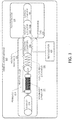
- the apparatus 100 comprises an integrated heat exchanger 102A and catalytic reactor 102B, a catalytic converter 104, a coil-type heat exchanger 106, a membrane separator 108, and an exhaust 110.
- the apparatus 100 is incorporated into the exhaust system of a vehicle (e.g., installed on the undercarriage of the vehicle) as discussed below with respect to FIG. 3 .
- the heat exchanger 102A and catalytic reactor 102B are integrated so that thermal energy extracted from exhaust gases in the heat exchanger 102A can be used to stimulate a reaction in the catalytic reactor 102B.
- the heat exchanger 102A receives the exhaust gases from a combustion engine. Thermal energy is extracted from the exhaust gases as they pass through the heat exchanger 102A thereby cooling down the exhaust gases before the exhaust gases enter the catalytic converter 104.
- the heat exchanger 102A allows for (1) waste heat to be recovered from the engine and used by the catalytic reactor 102B and (2) exhaust gases to be cooled before entering the other components of the apparatus 100.
- the membrane separator 108 can include a membrane that operates at relatively high pressure and temperatures lower than the temperature of the exhaust gas exiting the combustion engine.
- the catalytic reactor 102B includes a catalytic system, a photocatalytic system, an electro-catalytic system, or suitable combination thereof. Further, the catalytic reactor 102B can include a mixed, fluidized bed and a catalytic membrane.
- the catalyst can be a supported nanostructure catalyst that includes alumina, silica, and clay as support and active monometallic, bi-metallic and tri-metallic materials as active ingredients as discussed below.
- the catalytic reactor 102B contains a reaction to convert CO 2 and H 2 O to hydrocarbon fuel.
- the reaction can produce methane (CH 4 ) or mixed products with the release of oxygen as shown in the following reactions:
- the catalyst and reaction temperature can be tailored to maximize the production of certain products (e.g., ethanol).
- the nano catalyst used by the catalytic reactor 102B can be a metallic nano catalyst including ruthenium, manganese, and/or nickel.
- the metallic nano catalyst can be about 2 to 3 percent ruthenium, about 20 to 30 percent nickel, and about 15 to 20 percent manganese (e.g., 2 percent Ruthenium, 20 percent Nickel, and 15 percent Manganese).
- the reaction can be stimulated by the catalyst when H 2 O (steam) and CO 2 decompose over the nano catalyst surface to produce oxygen and hydrogen.
- the hydrogen and oxygen can react with the carbon to produce the hydrocarbon fuel.
- nascent oxygen resulting from the reaction can result in the generation of additional energy, which reduces the requirement for external thermal energy,
- exhaust gases can be emitted from 6.5 grams/sec to 200 grams/sec depending the speed of the vehicle.
- the maximum speed in the driving cycle is around 80 mph, which can be used to calculate a quantity of catalyst for commercial purposes.
- the amount of catalyst used was 0.5 grams, where the corresponding space velocity of the exhaust through the reactor was 6000 - 7200 hr -1 .
- the exhaust mass flow rate through a vehicle can vary from 6.5 g/s to 200 g/s.
- the total amount of catalyst used in the catalytic reactor 102B is about 120 grams.
- the level of conversion of in the reactor is dependent on the exhaust mass flow rate (i.e., the conversion rate in the reactor increases as the exhaust mass flow rate decreases).
- the catalytic converter 104 cleanses toxic substances from the vehicle exhaust.
- the catalytic converter 104 can include metallic catalysts for (1) oxidizing carbon monoxide to generate CO 2 and (2) oxidizing unburned hydrocarbons to generate H 2 O and CO 2 .
- the reactions in the catalytic converter 104 increase the temperature of the exhaust gases before they are passed to a coil type heat exchanger 106.
- the coil type heat exchanger 106 reduces the temperature of the exhaust gas before it is provided to the membrane separator 108.
- the coil type heat exchanger 106 can transfer thermal energy from the exhaust gas to reactants traveling towards the catalytic reactor 102B.
- the membrane separator 108 separates CO 2 and H 2 O from the other gases of the exhaust gases received from the coil type heat exchanger 106.
- the membrane separator 108 can include a variety of membranes, where the CO 2 and H 2 O is separated as permeate or retenate depending on the operating conditions (e.g., temperature).
- the separated CO 2 and H 2 O are passed to the catalytic reactor 102B, and the other gases as passed to the exhaust 110.
- the exhaust 110 can then emit the other gases from the vehicle.
- FIG. 2 an example process flow for converting exhaust gases to hydrocarbon fuel is shown.
- the exhaust gases leaving the vehicle engine enter a double-pipe heat exchanger 102A at a temperature of about 850 °C (i.e., the exhaust gases contain energy in the form of heat generated from combustion in the vehicle engine).
- the double-pipe heat exchanger 102A extracts thermal energy from the exhaust gases before emitting the exhaust gas in 203.
- the exhaust gases leave the double-pipe heat exchanger 102A at a temperature of about 350-500 °C before entering the catalytic converter 104.
- the catalytic converter 104 reactions occur to convert unburned gaseous components into N 2 , CO 2 , H 2 O, etc.
- the converted gases leave the catalytic converter 106 at a temperature of about 500-600 °C.
- the converted gases then pass through a coil type heat exchanger 106 to transfer further heat to reactants moving towards the catalytic reactor 102B.
- the converted gases enter the membrane separator 108 at about 200-300 °C.
- CO 2 and H 2 O are separated from the converted gases.
- the separated CO 2 and H 2 O pass through the coil-type heat exchanger 106 to raise the temperature of the CO 2 and H 2 O to about 500 °C.
- the remaining gases leave the membrane separator 108 and are emitted from the vehicle as exhaust.
- the heated CO 2 and H 2 O are passed to the catalytic reactor 102B.
- a nano catalyst stimulates a reaction that converts the CO 2 and H 2 O into hydrocarbon fuel.
- the hydrocarbon fuel is recycled into the car engine 216 (e.g., the hydrocarbon fuel can be passed to a fuel line, a carburetor, or a fuel tank) thereby reducing CO 2 emissions from the vehicle.
- the process flow arrangement of FIG. 2 cools the exhaust gases so that CO 2 and H 2 O can be separated from the exhaust gases at low temperatures in the membrane separator 108. At the same time, the temperature of the separated CO 2 and H 2 O moving towards the catalytic reactor 102B is raised by heat transfer from both the double-pipe heat exchanger 102A and coil-type heat exchanger 106. In some embodiments, the process flow arrangement utilizes the waste heat of the exhaust gases so that the reaction can be performed without external energy.
- the process flow arrangement can be installed on the undercarriage of the vehicle along the exhaust pipe as discussed below with respect to FIG. 3 .
- FIG. 3 an example apparatus installed on a vehicle undercarriage 302 is shown.
- An exhaust head pipe 306 of the vehicle receives exhaust gases from a combustion engine (not shown).
- the integrated heat exchanger 102A and catalytic reactor 102B is attached to the exhaust head pipe 306.
- the exhaust head pipe 306 and integrated heat exchanger 102A and catalytic reactor 102B are positioned under an engine section 304 of the vehicle (i.e., positioned under the combustion engine of the vehicle). Exhaust gases from the exhaust head pipe 306 are conveyed through the heat exchanger 102A to the catalytic converter 104.
- a heat shield 306 Adjacent to the engine section 304 is a heat shield 306 for protecting the vehicle from the heat of the exhaust gas as it passes through the example apparatus.
- the heat shield 306 encompasses the catalytic converter 104, the coil-type heat exchanger 106, the membrane separator 108, and the exhaust 110, each of which may be substantially similar to the respective components described above with respect to FIGS. 1 and 2 .
- permeate 210 i.e., CO 2 and H 2 O
- the coil-type heat exchanger 106 which transfers thermal energy from the exhaust gas to the permeate 210.
- the heated reactants 212 are then conveyed past the catalytic converter 104 to the catalytic reactor 102B. Further thermal energy can be transferred to the heated reactants 212 from the catalytic converter 104 and the heat exchanger 102A as the heated reactants flow towards and in the catalytic reactor 102B.
- the catalytic reactor 102B converts the heated reactants 212 to hydrocarbon fuel 214, which is then used as recycled fuel 216 for the vehicle.
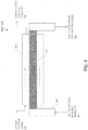
- FIG. 4 an example integrated heat exchanger and catalytic reactor 102A, 102B is shown.
- the integrated heat exchanger and catalytic reactor 102A, 102B can be installed between the combustion engine and the catalytic converter on a vehicle undercarriage.
- the exhaust gases 202 typically leave the engine at around 800 to 900 °C and are quickly cooled to about 500 to 600 °C before leaving an outer pipe 402 of the integrated heat exchanger and catalytic reactor 102A, 102B.
- the integrated heat exchanger and catalytic reactor 102A, 102B is positioned to recover waste heat from the exhaust gases 202 and to supplement the heat requirements of endothermic reactions taking place in an inner pipe 404 of the integrated heat exchanger and catalytic reactor 102A, 102B.
- the integrated heat exchanger and catalytic reactor 102A, 102B is a standard double-pipe heat exchanger in which the inner pipe 404 holds the catalyst 406 for reaction and the outer pipe 402 provide the passage for the exhaust gas.
- the integrated heat exchanger and catalytic reactor 102A, 102B can be a shell and tube type heat exchanger including an inside shell having multiple tubes holding the catalyst 406, where the multiple tubes can be attached to tube-sheets at both ends of the double-pipe heat exchanger.
- the multiple tubes provide a larger surface area for the heat transfer.
- the outer pipe 402 can be properly insulated to conserve heat and facilitate the heat transfer.
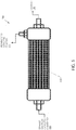
- the membrane separator 108 includes a membrane 502 for separating permeate 210 (CO 2 and H 2 O) from exhaust gases received from the catalytic converter 206.
- the membrane 502 can have a hollow fiber configuration.
- the membrane 502 includes a selective membrane layer (not shown) that is coated on stable supports (e.g., ceramic hollow fibers, etc.).
- the membrane 502 can have a tubular configuration.
- the selective membrane layer is coated on a porous tubular support (e.g., porous alumina tubes, ceramic tubes, porous metallic tubes, etc.).
- sweep gas (not shown) can be injected into the membrane separator 108 to facilitate the collection of the permeate 210.
- Table I below shows example membranes that can be used in the membrane separator 108.
- Example Membranes for Membrane Separator 108 Example # Selective membrane layer material Support layer 1 Silica Ceramic support with alumina/Zirconia interlayer 2 Silica Porous metallic support with zirconias or alumina interlayer 3 Cobalt embedded silica Porous metallic/ceramic support 4 Carbon molecular sieve (CMS) Alumina support 5 Y-type zeolites Alumina support 6 Carbon based (prepared by carbonization of polyimides or similar polymers) Alumina support 7 Faujasite (FAU)-type zeolite
- CMS Carbon molecular sieve
- thermodynamic calculations for an exhaust system e.g., apparatus 100 of FIG. 1 .
- Specific tasks performed in the study include:
- Thermodynamic simulations of engine cycles, delivered power (i.e., indicated mean effective pressure (IMEP)), engine efficiencies, fuel consumption, estimated exhaust temperatures and emissions were conducted using a gas-dynamics engine system simulation platform. Specifically, calculations were performed using the gas-dynamics engine system simulation platform with input data based on a modern single cylinder spark ignition engine as used in laboratory testing, where the ignition engine had inlet and exhaust geometry and Port Fuel Injection (PFI). The model was fully validated for different fuels and combustion conditions against available experimental data. Further, the conditions and gas dynamics of the engine inlet and exhaust geometry were based on the laboratory engine, and the heat transfer in the laboratory engine was based on typical default values.
- delivered power i.e., indicated mean effective pressure (IMEP)
- engine efficiencies fuel consumption
- estimated exhaust temperatures and emissions were conducted using a gas-dynamics engine system simulation platform. Specifically, calculations were performed using the gas-dynamics engine system simulation platform with input data based on a modern single cylinder spark ignition engine as used in laboratory testing, where the ignition engine
- Table II above shows that the average exhaust temperatures at the exhaust head exit is estimated to be around 1152 K (879 °C), and it has been shown that exhaust gases emitted from a vehicle have a temperature of around 520 to 580 °C. Accordingly, the heat loss by the exhaust gases while traveling through the exhaust system is about 300 to 360 °C.
- Table III shows heat liberated (in kJ/kg) from a typical gasoline fuel as a result of combustion under the effect of varying air flows.
- Table IV presents the composition of gas shown in mole fraction when a fuel is burned under excess air conditions.
- Table III Heat liberated from fuel blend, kJ/kg for different values of combustion air. 100 % C 8 H 18 Excess air factor ( ⁇ ) 39583.33 0.9 47947.06 1 47837.57 1.5
- Table IV Products mole fractions for lean fuel burning (Excess Air) Percentage H 2 in Fuel XCO 2 XH 2 O XN 2 XO 2 0 0.08533334 0.096 0.752 0.06666667
- both (1) the heat energy recovered from the waste energy generated by the initial combustion of the fuel (i.e., approximately 121 kJ/s) and (2) the heat energy recovered from the catalytic converter (i.e., -2.8266 x 10 6 kJ/kmol) can be used to heat the reactants provided to the catalytic reactor thereby facilitating the conversion of H 2 O and CO 2 to hydrocarbon fuel as discussed above with respect to FIGS. 1-5 .
Landscapes
- Chemical & Material Sciences (AREA)
- Engineering & Computer Science (AREA)
- Chemical Kinetics & Catalysis (AREA)
- Combustion & Propulsion (AREA)
- Oil, Petroleum & Natural Gas (AREA)
- Organic Chemistry (AREA)
- Mechanical Engineering (AREA)
- General Engineering & Computer Science (AREA)
- General Chemical & Material Sciences (AREA)
- Materials Engineering (AREA)
- Analytical Chemistry (AREA)
- Inorganic Chemistry (AREA)
- Health & Medical Sciences (AREA)
- Biomedical Technology (AREA)
- Environmental & Geological Engineering (AREA)
- Life Sciences & Earth Sciences (AREA)
- Geology (AREA)
- Exhaust Gas After Treatment (AREA)
- Drying Of Gases (AREA)
- Treating Waste Gases (AREA)
- Separation Using Semi-Permeable Membranes (AREA)
- Dispersion Chemistry (AREA)
- Catalysts (AREA)
Description
- The present invention relates to a process for reducing vehicle emissions by converting carbon dioxide to hydrocarbon fuel. More specifically, embodiments of the present invention utilize an on-board heat exchanger and catalytic converter to convert vehicle exhaust into hydrocarbon fuel for the vehicle's combustion engine.
- The automobile industry has recognized for decades that vehicle emissions are harmful to the public health and the environment. It is also well-known that conventional methods of reducing vehicle emissions are inefficient. Typically, vehicle emissions may be reduced by increasing engine efficiency and/or cleansing the exhaust after combustion. For example, vehicle exhaust may be cleansed using secondary air injection, exhaust gas recirculation, and/or catalytic conversion.
- Typically, a catalytic converter includes metallic catalyst(s) (e.g., platinum, palladium, rhodium) for converting toxic emissions into non-toxic substances. The toxic emissions converted may include carbon monoxide, nitrogen oxides, and unburned hydrocarbons. For example, the carbon monoxide may be oxidized and converted to carbon dioxide, where the catalyst stimulates the oxidation.
- The use of a catalytic converter fails to resolve all the challenges related to reducing vehicle emissions. For example, catalytic converters fail to reduce the amount of hydrocarbon fuel being combusted. Further, catalytic converters produce carbon dioxide, which is a greenhouse gas that contributes to global warming.
- Therefore, it would be desirable to have an improved process for reducing vehicle emissions. Preferably, it would be desirable to have a process that converts emissions into usable fuel. Further, it would be desirable to have a process that also reduces the amount of carbon dioxide being emitted.
US 2008/0283411 discloses an apparatus and a method for producing hydrocarbons from carbon dioxide and water produced in hydrocarbon combustion. - The apparatus for emission reduction from mobile sources of the invention is defined in claim 1 and includes a heat exchanger to extract thermal energy from exhaust gases of a combustion engine, the combustion engine powering propulsion of a vehicle; a membrane separator to separate water and carbon dioxide from the exhaust gases; and a catalytic reactor having a nano catalyst, the catalytic reactor to contain a reaction of the water and the carbon dioxide that produces hydrocarbon fuel, the reaction being facilitated by the nano catalyst. In one embodiment, the catalytic reactor receives the water and the carbon dioxide from the membrane separator and uses the thermal energy from the heat exchanger to stimulate the reaction of the water and the carbon dioxide. The process of the invention is defined in claim 9.
- In one embodiment, the nano catalyst is a multimetallic nano catalyst that includes at least one of ruthenium, manganese, and nickel. In another embodiment, the nano catalyst is 2 to 3 percent ruthenium, 20 to 30 percent nickel, and 15 to 20 percent manganese. In yet another embodiment, the nano catalyst is 2 percent ruthenium, 20 percent nickel, and 15 percent manganese.
- In one embodiment, the membrane separator includes a selective membrane layer that is a silica-based membrane layer, a carbon-based membrane layer, or a zeolite membrane layer and a support layer that is a ceramic support, a metallic support, or an alumina support.
- In one embodiment, the catalytic reactor is encompassed by the heat exchanger such that the thermal energy is directed to a portion of the catalytic reactor holding the nano catalyst. In one embodiment, the catalytic reactor includes multiple tubes for holding the nano catalyst, the multiple tubes providing increased surface area for receiving the thermal energy from the heat exchanger.
- In one embodiment, the hydrocarbon fuel includes ethanol and propyne.
- These and other features, aspects, and advantages of the present invention will become better understood with regard to the following description, claims, and accompanying drawings. It is to be noted, however, that the drawings illustrate only several embodiments of the invention and are therefore not to be considered limiting of the invention's scope as it can admit to other equally effective embodiments.
-
FIG. 1 shows an apparatus in accordance with one or more embodiments of the present invention. -
FIG. 2 shows a process flow in accordance with one or more embodiments of the present invention. -
FIG. 3 shows an example apparatus in accordance with one or more embodiments of the present invention. -
FIG. 4 shows a heat exchanger and catalytic reactor in accordance with one or more embodiments of the present invention. -
FIG. 5 shows a heat exchanger in accordance with one or more embodiments of the present invention. - The apparatus for emission reduction of vehicles includes a heat exchanger for extracting thermal energy from exhaust gas of a combustion vehicle, the combustion engine powering propulsion of a vehicle; a membrane separator for separating water and carbon dioxide from the exhaust gas; and a catalytic reactor comprising a nano catalyst for containing a reaction of the water and carbon dioxide that produces hydrocarbon fuel. Further, the thermal energy extracted by the heat exchanger stimulates the reaction of the water and the carbon dioxide.
- As shown in
FIG. 1 , theapparatus 100 comprises an integratedheat exchanger 102A and catalytic reactor 102B, acatalytic converter 104, a coil-type heat exchanger 106, amembrane separator 108, and anexhaust 110. In one embodiment, theapparatus 100 is incorporated into the exhaust system of a vehicle (e.g., installed on the undercarriage of the vehicle) as discussed below with respect toFIG. 3 . - In one embodiment, the
heat exchanger 102A and catalytic reactor 102B are integrated so that thermal energy extracted from exhaust gases in theheat exchanger 102A can be used to stimulate a reaction in the catalytic reactor 102B. Theheat exchanger 102A receives the exhaust gases from a combustion engine. Thermal energy is extracted from the exhaust gases as they pass through theheat exchanger 102A thereby cooling down the exhaust gases before the exhaust gases enter thecatalytic converter 104. Theheat exchanger 102A allows for (1) waste heat to be recovered from the engine and used by the catalytic reactor 102B and (2) exhaust gases to be cooled before entering the other components of theapparatus 100. For example, themembrane separator 108 can include a membrane that operates at relatively high pressure and temperatures lower than the temperature of the exhaust gas exiting the combustion engine. - In some embodiments, the catalytic reactor 102B includes a catalytic system, a photocatalytic system, an electro-catalytic system, or suitable combination thereof. Further, the catalytic reactor 102B can include a mixed, fluidized bed and a catalytic membrane. The catalyst can be a supported nanostructure catalyst that includes alumina, silica, and clay as support and active monometallic, bi-metallic and tri-metallic materials as active ingredients as discussed below.
- In one embodiment, the catalytic reactor 102B contains a reaction to convert CO2 and H2O to hydrocarbon fuel. For example, the reaction can be a general reaction to produce alcohols such as: nCO2 + (n+1)H2O → Cn H2n+1 OH + (3n/2) O2, where n = 1, 2, 3, 4, 5, 6, etc. (e.g., when n=1 then the product is CH3OH (methanol), when n=2 then the product is C2H5OH (ethanol), etc.). In another example, the reaction can be targeted for alkane production such as: 2nH2O + nCO2 → CnH2n+2 + 2nO2, where n = 1, 2, 3, 4, 5, 6, etc. In yet another example, the reaction can produce methane (CH4) or mixed products with the release of oxygen as shown in the following reactions:
- A catalyst stimulated reaction producing ethanol, propyne, and oxygen at 673 K and atmospheric pressure - 5CO2 + 5H2O → C2H5OH + H3C-C≡CH + 7 O2
- A catalyst stimulated reaction producing methanol, ethanol, oxygen, and propyne
- 6CO2 + 7H2O → CH3OH + C2H5OH + 17/2 O2 + H3C-C≡CH
- In this example, the catalyst and reaction temperature can be tailored to maximize the production of certain products (e.g., ethanol). Further, the nano catalyst used by the catalytic reactor 102B can be a metallic nano catalyst including ruthenium, manganese, and/or nickel. Specifically, the metallic nano catalyst can be about 2 to 3 percent ruthenium, about 20 to 30 percent nickel, and about 15 to 20 percent manganese (e.g., 2 percent Ruthenium, 20 percent Nickel, and 15 percent Manganese). The reaction can be stimulated by the catalyst when H2O (steam) and CO2 decompose over the nano catalyst surface to produce oxygen and hydrogen. At this stage, the hydrogen and oxygen can react with the carbon to produce the hydrocarbon fuel. In some cases, nascent oxygen resulting from the reaction can result in the generation of additional energy, which reduces the requirement for external thermal energy,
- An example nano catalyst is described in Hussain S.T., et al., Nano Catalyst for CO2 Conversion to Hydrocarbons, Journal of Nano Systems & Technology, Oct. 31, 2009. In this article, the example nano catalyst is prepared as follows:
- A solution of ruthenium, trichloride (0.103 g), manganese nitrate tetrahydrate (2.285 g) and nickel nitrate hexahydrate (2.47 g) (analar grade) is prepared in deionized H2O and acidified with dilute hydrochloric acid to prevent the precipitation of hydroxide.
- A portion of the slurry (10 cm3) is then added to a titanium dioxide catalyst support (3.95 g), (350 m2g-1) in an evaporation basin, where the mixture is magnetically stirred for 20 minutes and dried at 395 K overnight.
- The prepared catalyst sample is then calcined in air for 6 hours at 600°C.
- Based on a typical driving cycle (e.g. the USO6 drive cycle), exhaust gases can be emitted from 6.5 grams/sec to 200 grams/sec depending the speed of the vehicle. In this case, the maximum speed in the driving cycle is around 80 mph, which can be used to calculate a quantity of catalyst for commercial purposes. In laboratory tests, the amount of catalyst used was 0.5 grams, where the corresponding space velocity of the exhaust through the reactor was 6000 - 7200 hr-1. Comparatively, the exhaust mass flow rate through a vehicle can vary from 6.5 g/s to 200 g/s. In some embodiments, based on the laboratory quantity and the typical driving cycle, the total amount of catalyst used in the catalytic reactor 102B is about 120 grams. In this case, the level of conversion of in the reactor is dependent on the exhaust mass flow rate (i.e., the conversion rate in the reactor increases as the exhaust mass flow rate decreases).
- In one embodiment, the
catalytic converter 104 cleanses toxic substances from the vehicle exhaust. Specifically, thecatalytic converter 104 can include metallic catalysts for (1) oxidizing carbon monoxide to generate CO2 and (2) oxidizing unburned hydrocarbons to generate H2O and CO2. The reactions in thecatalytic converter 104 increase the temperature of the exhaust gases before they are passed to a coil type heat exchanger 106. - In one embodiment, the coil type heat exchanger 106 reduces the temperature of the exhaust gas before it is provided to the
membrane separator 108. The coil type heat exchanger 106 can transfer thermal energy from the exhaust gas to reactants traveling towards the catalytic reactor 102B. - In one embodiment, the
membrane separator 108 separates CO2 and H2O from the other gases of the exhaust gases received from the coil type heat exchanger 106. Themembrane separator 108 can include a variety of membranes, where the CO2 and H2O is separated as permeate or retenate depending on the operating conditions (e.g., temperature). The separated CO2 and H2O are passed to the catalytic reactor 102B, and the other gases as passed to theexhaust 110. Theexhaust 110 can then emit the other gases from the vehicle. - Turning to
FIG. 2 , an example process flow for converting exhaust gases to hydrocarbon fuel is shown. In 202, the exhaust gases leaving the vehicle engine enter a double-pipe heat exchanger 102A at a temperature of about 850 °C (i.e., the exhaust gases contain energy in the form of heat generated from combustion in the vehicle engine). The double-pipe heat exchanger 102A extracts thermal energy from the exhaust gases before emitting the exhaust gas in 203. The exhaust gases leave the double-pipe heat exchanger 102A at a temperature of about 350-500 °C before entering thecatalytic converter 104. In thecatalytic converter 104 reactions occur to convert unburned gaseous components into N2, CO2, H2O, etc. In 204, the converted gases leave the catalytic converter 106 at a temperature of about 500-600 °C. - The converted gases then pass through a coil type heat exchanger 106 to transfer further heat to reactants moving towards the catalytic reactor 102B. In 206, the converted gases enter the
membrane separator 108 at about 200-300 °C. In themembrane separator 108, CO2 and H2O are separated from the converted gases. In 210, the separated CO2 and H2O pass through the coil-type heat exchanger 106 to raise the temperature of the CO2 and H2O to about 500 °C. In 110, the remaining gases leave themembrane separator 108 and are emitted from the vehicle as exhaust. In 212, the heated CO2 and H2O are passed to the catalytic reactor 102B. In the catalytic reactor 102B, a nano catalyst stimulates a reaction that converts the CO2 and H2O into hydrocarbon fuel. In 214, the hydrocarbon fuel is recycled into the car engine 216 (e.g., the hydrocarbon fuel can be passed to a fuel line, a carburetor, or a fuel tank) thereby reducing CO2 emissions from the vehicle. - The process flow arrangement of
FIG. 2 cools the exhaust gases so that CO2 and H2O can be separated from the exhaust gases at low temperatures in themembrane separator 108. At the same time, the temperature of the separated CO2 and H2O moving towards the catalytic reactor 102B is raised by heat transfer from both the double-pipe heat exchanger 102A and coil-type heat exchanger 106. In some embodiments, the process flow arrangement utilizes the waste heat of the exhaust gases so that the reaction can be performed without external energy. The process flow arrangement can be installed on the undercarriage of the vehicle along the exhaust pipe as discussed below with respect toFIG. 3 . - Turning to
FIG. 3 , an example apparatus installed on avehicle undercarriage 302 is shown. Anexhaust head pipe 306 of the vehicle receives exhaust gases from a combustion engine (not shown). Theintegrated heat exchanger 102A and catalytic reactor 102B is attached to theexhaust head pipe 306. In this example, theexhaust head pipe 306 andintegrated heat exchanger 102A and catalytic reactor 102B are positioned under anengine section 304 of the vehicle (i.e., positioned under the combustion engine of the vehicle). Exhaust gases from theexhaust head pipe 306 are conveyed through theheat exchanger 102A to thecatalytic converter 104. - Adjacent to the
engine section 304 is aheat shield 306 for protecting the vehicle from the heat of the exhaust gas as it passes through the example apparatus. In this example, theheat shield 306 encompasses thecatalytic converter 104, the coil-type heat exchanger 106, themembrane separator 108, and theexhaust 110, each of which may be substantially similar to the respective components described above with respect toFIGS. 1 and 2 . As shown inFIG. 3 , permeate 210 (i.e., CO2 and H2O) from themembrane separator 108 is conveyed to the coil-type heat exchanger 106, which transfers thermal energy from the exhaust gas to thepermeate 210. Theheated reactants 212 are then conveyed past thecatalytic converter 104 to the catalytic reactor 102B. Further thermal energy can be transferred to theheated reactants 212 from thecatalytic converter 104 and theheat exchanger 102A as the heated reactants flow towards and in the catalytic reactor 102B. The catalytic reactor 102B converts theheated reactants 212 tohydrocarbon fuel 214, which is then used as recycled fuel 216 for the vehicle. - Turning to
FIG. 4 , an example integrated heat exchanger andcatalytic reactor 102A, 102B is shown. As discussed above, the integrated heat exchanger andcatalytic reactor 102A, 102B can be installed between the combustion engine and the catalytic converter on a vehicle undercarriage. Theexhaust gases 202 typically leave the engine at around 800 to 900 °C and are quickly cooled to about 500 to 600 °C before leaving anouter pipe 402 of the integrated heat exchanger andcatalytic reactor 102A, 102B. The integrated heat exchanger andcatalytic reactor 102A, 102B is positioned to recover waste heat from theexhaust gases 202 and to supplement the heat requirements of endothermic reactions taking place in aninner pipe 404 of the integrated heat exchanger andcatalytic reactor 102A, 102B. - In this example, the integrated heat exchanger and
catalytic reactor 102A, 102B is a standard double-pipe heat exchanger in which theinner pipe 404 holds thecatalyst 406 for reaction and theouter pipe 402 provide the passage for the exhaust gas. In another example, the integrated heat exchanger andcatalytic reactor 102A, 102B can be a shell and tube type heat exchanger including an inside shell having multiple tubes holding thecatalyst 406, where the multiple tubes can be attached to tube-sheets at both ends of the double-pipe heat exchanger. The multiple tubes provide a larger surface area for the heat transfer. In either example, theouter pipe 402 can be properly insulated to conserve heat and facilitate the heat transfer. - Turning to
FIG. 5 , anexample membrane separator 108 is shown. Themembrane separator 108 includes amembrane 502 for separating permeate 210 (CO2 and H2O) from exhaust gases received from thecatalytic converter 206. In some embodiments, themembrane 502 can have a hollow fiber configuration. In this case, themembrane 502 includes a selective membrane layer (not shown) that is coated on stable supports (e.g., ceramic hollow fibers, etc.). In other embodiments, themembrane 502 can have a tubular configuration. In this case, the selective membrane layer is coated on a porous tubular support (e.g., porous alumina tubes, ceramic tubes, porous metallic tubes, etc.). Optionally, sweep gas (not shown) can be injected into themembrane separator 108 to facilitate the collection of thepermeate 210. Table I below shows example membranes that can be used in themembrane separator 108.Table I: Example Membranes for Membrane Separator 108Example # Selective membrane layer material Support layer 1 Silica Ceramic support with alumina/Zirconia interlayer 2 Silica Porous metallic support with zirconias or alumina interlayer 3 Cobalt embedded silica Porous metallic/ceramic support 4 Carbon molecular sieve (CMS) Alumina support 5 Y-type zeolites Alumina support 6 Carbon based (prepared by carbonization of polyimides or similar polymers) Alumina support 7 Faujasite (FAU)-type zeolite - The present invention is illustrated by the following example, which is presented for illustrative purposes only and is not intended as limiting the scope of the invention which is defined by the appended claims.
- A study was performed to characterize (1) the heat released from the exhaust gases, (2) the temperature of the exhaust gases, and (3) the emission composition. In addition, thermodynamic calculations for an exhaust system (e.g.,
apparatus 100 ofFIG. 1 ) were performed. Specific tasks performed in the study include: - Estimating exhaust gases temperature.
- Determining an availability of energy from exhaust engine gases for operating the catalytic reactor at 800 to 850 °C.
- Determining a composition of exhaust emissions.
- Thermodynamic simulations of engine cycles, delivered power (i.e., indicated mean effective pressure (IMEP)), engine efficiencies, fuel consumption, estimated exhaust temperatures and emissions were conducted using a gas-dynamics engine system simulation platform. Specifically, calculations were performed using the gas-dynamics engine system simulation platform with input data based on a modern single cylinder spark ignition engine as used in laboratory testing, where the ignition engine had inlet and exhaust geometry and Port Fuel Injection (PFI). The model was fully validated for different fuels and combustion conditions against available experimental data. Further, the conditions and gas dynamics of the engine inlet and exhaust geometry were based on the laboratory engine, and the heat transfer in the laboratory engine was based on typical default values. Simulations were performed with a blend of 67% iso-octane and 33% toluene measured by liquid volume, which converted to mass fractions is 62.2%/37.8% isooctane/toluene. This fuel blend is often used in laboratory testing as a reproducible representation of modern gasoline.
- Analysis of the simulation results presented below in Table 11 show that:
- The average exhaust temperatures appear to be about 1152 K (879 °C) with the use of vaporized gasoline, where maximum temperatures are achieved at the exhaust valve opening. However, the average exhaust temperatures at the valve and at the head exit are about 1188 K (915 °C) and 1152 K (879 °C) respectively.
- Enthalpy available from exhaust gases (with a maximum exhaust temperature of 1123K (850 °C)) for gasoline is about 1.559E+05 kJ/kmol.
- For the gasoline simulation, the indicated engine efficiency obtained was 40.1 %.
- Table II above shows that the average exhaust temperatures at the exhaust head exit is estimated to be around 1152 K (879 °C), and it has been shown that exhaust gases emitted from a vehicle have a temperature of around 520 to 580 °C. Accordingly, the heat loss by the exhaust gases while traveling through the exhaust system is about 300 to 360 °C.
- Table III below shows heat liberated (in kJ/kg) from a typical gasoline fuel as a result of combustion under the effect of varying air flows. Table IV below presents the composition of gas shown in mole fraction when a fuel is burned under excess air conditions.
Table III: Heat liberated from fuel blend, kJ/kg for different values of combustion air. 100 % C8H18 Excess air factor (λ) 39583.33 0.9 47947.06 1 47837.57 1.5 Table IV: Products mole fractions for lean fuel burning (Excess Air) Percentage H2 in Fuel XCO2 XH2O XN2 XO2 0 0.08533334 0.096 0.752 0.06666667 - As an example of energy recovery from waste heat of a vehicle engine, the following are results of testing performed by Clean Power Technologies:
- With a diesel engine running at 1400 rpm and producing 405 bhp, the exhaust gas temperature is 549 °C.
- At a mass flow rate of 0.46 Kg/s, the exhaust gas has an energy value of 268 kJ/s
- A heat exchanger can recover 250 °C from the exhaust gas, which is 45% of the energy (i.e., approximately 121 kJ/s).
- The system can then convert the recovered thermal energy to mechanical power with a 19 KW output, providing an energy efficiency of around 16% for the heat recovery.
- The recovered energy is equivalent to recovering about 5-10% of the vehicle engine running power.
- Through research it is shown that there is also energy available from the catalytic converter of a vehicle. Specifically, the chemical reactions occurring in a catalytic converter release a total heat of -2.8266 x 10⁶ kJ/kmol.
- Both (1) the heat energy recovered from the waste energy generated by the initial combustion of the fuel (i.e., approximately 121 kJ/s) and (2) the heat energy recovered from the catalytic converter (i.e., -2.8266 x 10⁶ kJ/kmol) can be used to heat the reactants provided to the catalytic reactor thereby facilitating the conversion of H2O and CO2 to hydrocarbon fuel as discussed above with respect to
FIGS. 1-5 . - The singular forms "a", "an" and "the" include plural referents, unless the context clearly dictates otherwise. Optional or optionally means that the subsequently described event or circumstances may or may not occur. The description includes instances where the event or circumstance occurs and instances where it does not occur. Ranges may be expressed herein as from about one particular value, and/or to about another particular value. When such a range is expressed, it is to be understood that another embodiment is from the one particular value and/or to the other particular value, along with all combinations within said range.
- While the invention has been described in conjunction with specific embodiments thereof, it is evident that many alternatives, modifications, and variations within the scope of the claims will be apparent to those skilled in the art in light of the foregoing description. Accordingly, it is intended to embrace all such alternatives, modifications, and variations as fall within the scope of the appended claims. The present invention may suitably comprise, consist or consist essentially of the elements disclosed and may be practiced in the absence of an element not disclosed.
| 100 % Gasoline to ICE | |
| Fuel | (67% iso-octane 33% toluene by liq vol - 62.2%/37.8% by mass, vaporized) |
| LHV (MJ/kg) | 43.340 |
| Indicated power (HP) | 22.060 |
| Indicated power (kW) | 16.225 |
| Indicated mean effective pressure (bar) | 11.630 |
| Indicated specific fuel consumption (kg/kWh) | 0.208 |
| Indicated engine efficiency (%) | 40.1 |
| Average exhaust temperature @ valve (K) | 1,185.0 |
| Average exhaust temperature @ exit (K) | 1,151.9 |
| Maximum exhaust temperature (K) | 1,247.0 |
| NOx (ppm) | 3,575.0 |
| NOx (g/kWh ind) | 12.0 |
| HC (ppm) | 2,861.0 |
| HC (g/kWh ind) | 4.5 |
| CO (ppm) | 1,311.0 |
| CO (g/kWh ind) | 4.1 |
| Total C in HC and CO (g Carbon / kWh ind) - approx. | 5.865 |
| Mass fraction of C in fuel entering engine | 0.862 |
| Total C in fuel entering engine (g Carbon / kWh ind) | 179.342 |
| CO2 in exhaust (g CO2 / kWh ind) - if all C into CO2 | 657.586 |
| CO2 in exhaust (ppm CO2) - if all C into CO2 | 133,937.0 |
| CO2 in exhaust (vol % CO2) - if all C into CO2 | 13.39370 |
Claims (15)
- An on-board, catalytic apparatus characterized by:a heat exchanger (102A) operable to extract thermal energy from exhaust gases of a combustion engine, the combustion engine powering propulsion of a vehicle;a membrane separator (108) operable to separate water and carbon dioxide from the exhaust gases; anda catalytic reactor (102B) contained in a body of the heat exchanger (102A), the catalytic reactor (102B) operable to:receive the water and the carbon dioxide from the membrane separator (108);contain a reaction of the water and the carbon dioxide that produces hydrocarbon fuel, the reaction being facilitated by a nano catalyst; anduse the thermal energy from the heat exchanger (102A) to stimulate the reaction of the water and the carbon dioxide.
- The apparatus as claimed in claim 1, wherein the nano catalyst is a multimetallic nano catalyst that comprises at least one of ruthenium, manganese, and nickel.
- The apparatus as claimed in any of the preceding claims, wherein the nano catalyst is 2 to 3 percent ruthenium, 20 to 30 percent nickel, and 15 to 20 percent manganese.
- The apparatus as claimed in claim 3, wherein the nano catalyst is 2 percent ruthenium, 20 percent nickel, and 15 percent manganese.
- The apparatus as claimed in any of the preceding claims, wherein the membrane separator (108) comprises:a selective membrane layer that is a silica-based membrane layer, a carbon-based membrane layer, or a zeolite membrane layer; anda support layer that is a ceramic support, a metallic support, or an alumina support.
- The apparatus as claimed in any of the preceding claims, wherein the catalytic reactor (102B) is encompassed by the heat exchanger (102A) such that the thermal energy is directed to a portion of the catalytic reactor (102B) holding the nano catalyst.
- The apparatus as claimed in claim 6, wherein the catalytic reactor (102B) comprises multiple tubes for holding the nano catalyst, the multiple tubes providing increased surface area for receiving the thermal energy from the heat exchanger (102A).
- The apparatus as claimed in any of the preceding claims, wherein the hydrocarbon fuel comprises ethanol and propyne.
- A process for on-board carbon dioxide conversion to hydrocarbon fuel, the process characterized by the steps of:extracting thermal energy from exhaust gases of a combustion engine, the combustion engine powering propulsion of a vehicle;separating water and carbon dioxide from the exhaust gases;converting the water and the carbon dioxide to hydrocarbon fuel by performing a reaction that is facilitated by a nano catalyst, the reaction being stimulated by the thermal energy extracted from the exhaust gases; andfeeding the hydrocarbon fuel into the combustion engine for combustion.
- The process as claimed in claim 9, wherein the nano catalyst is a multimetallic nano catalyst that comprises at least one of ruthenium, manganese, and nickel.
- The process as claimed in any of claims 9-10, wherein the nano catalyst is 2 to 3 percent ruthenium, 20 to 30 percent nickel, and 15 to 20 percent manganese.
- The process as claimed in claim 11, wherein the nano catalyst is 2 percent ruthenium, 20 percent nickel, and 15 percent manganese.
- The process as claimed in any of claims 9-12, further characterized by the step of cooling the exhaust gases to 200 to 300 degrees centigrade prior to separating the water and the carbon dioxide from the exhaust gases.
- The process as claimed in any of claims 9-13, further characterized by the step of oxidizing carbon monoxide in the exhaust gases to produce carbon dioxide.
- The process as claimed in any of claims 9-14, wherein the hydrocarbon fuel comprises ethanol and propyne, optionally wherein the reaction is 5CO2 + 5H2O → C2H5OH + H3C-C≡CH + 7 O2, wherein CO2 is the carbon dioxide, H2O is the water, C2H5OH is the ethanol, H3C-C≡CH is the propyne, and O2 is oxygen.
Applications Claiming Priority (2)
| Application Number | Priority Date | Filing Date | Title |
|---|---|---|---|
| US201161550699P | 2011-10-24 | 2011-10-24 | |
| PCT/US2012/061603 WO2013063052A1 (en) | 2011-10-24 | 2012-10-24 | Emission reduction from mobile sources by on-board carbon dioxide conversion to fuel |
Publications (2)
| Publication Number | Publication Date |
|---|---|
| EP2771431A1 EP2771431A1 (en) | 2014-09-03 |
| EP2771431B1 true EP2771431B1 (en) | 2017-11-22 |
Family
ID=47146714
Family Applications (1)
| Application Number | Title | Priority Date | Filing Date |
|---|---|---|---|
| EP12783772.2A Not-in-force EP2771431B1 (en) | 2011-10-24 | 2012-10-24 | Emission reduction from mobile sources by on-board carbon dioxide conversion to fuel |
Country Status (6)
| Country | Link |
|---|---|
| US (2) | US8863701B2 (en) |
| EP (1) | EP2771431B1 (en) |
| JP (2) | JP6006324B2 (en) |
| KR (1) | KR101867652B1 (en) |
| CN (2) | CN105257435B (en) |
| WO (1) | WO2013063052A1 (en) |
Families Citing this family (36)
| Publication number | Priority date | Publication date | Assignee | Title |
|---|---|---|---|---|
| EP4729100A3 (en) | 2009-12-23 | 2026-06-03 | Fisher & Paykel Healthcare Limited | Patient interface and headgear |
| JP5904108B2 (en) * | 2011-12-19 | 2016-04-13 | 株式会社デンソー | Exhaust heat exchanger |
| CN107626023B (en) | 2012-08-08 | 2021-03-02 | 费雪派克医疗保健有限公司 | Interface assembly for use in providing respiratory therapy |
| US20140102297A1 (en) * | 2012-10-17 | 2014-04-17 | Saudi Arabian Oil Company | Method for removal of co2 from exhaust gas using facilitated transport membranes and steam sweeping |
| GB2561734B (en) | 2013-04-24 | 2019-02-20 | Fisher & Paykel Healthcare Ltd | Automatically adjusting headgear for patient interface |
| TWI780489B (en) | 2014-09-16 | 2022-10-11 | 紐西蘭商費雪 & 佩凱爾關心健康有限公司 | Intramold headgear |
| CN122272964A (en) | 2014-09-16 | 2026-06-26 | 费雪派克医疗保健有限公司 | Headgear assembly and interface assembly with headgear |
| US10646680B2 (en) | 2014-09-19 | 2020-05-12 | Fisher & Paykel Healthcare Limited | Headgear assemblies and interface assemblies with headgear |
| EP3310880B1 (en) * | 2015-06-16 | 2019-12-11 | Saudi Arabian Oil Company | Method for on board conversion of co2 to fuel |
| GB2540798A (en) * | 2015-07-28 | 2017-02-01 | John Brown Allan | Method of recaiming and utilizing water and carbon dioxide from the exhaust system of an internal combustion engine to achieve a near zero greenhouse gas |
| CN105604667A (en) * | 2015-12-31 | 2016-05-25 | 北京建筑大学 | A diesel engine CO2 capture system and its working method |
| SG11201807705RA (en) | 2016-03-16 | 2018-10-30 | Fisher & Paykel Healthcare Ltd | Directional lock for interface headgear arrangement |
| AU2017234345B2 (en) | 2016-03-16 | 2022-03-03 | Fisher & Paykel Healthcare Limited | Intra-mould substrate |
| CN109152905B (en) | 2016-03-16 | 2022-07-19 | 费雪派克医疗保健有限公司 | Strap assembly, strap connector, headgear assembly, method of forming headgear, tubular connector, patient interface, and method of joining straps |
| JP2019135378A (en) * | 2016-04-20 | 2019-08-15 | 株式会社日立製作所 | Internal combustion engine |
| US10312536B2 (en) | 2016-05-10 | 2019-06-04 | Hamilton Sundstrand Corporation | On-board aircraft electrochemical system |
| US10300431B2 (en) | 2016-05-31 | 2019-05-28 | Hamilton Sundstrant Corporation | On-board vehicle inert gas generation system |
| US10307708B2 (en) | 2016-06-24 | 2019-06-04 | Hamilton Sundstrand Corporation | Fuel tank system and method |
| DE102016008835A1 (en) | 2016-07-20 | 2018-01-25 | Norbert Lorenz Mergel | Integrated exhaust gas utilization and fuel gasification plant for combustion engines of all kinds |
| JP2018035767A (en) * | 2016-09-01 | 2018-03-08 | ダイハツディーゼル株式会社 | Internal combustion engine |
| US10427800B2 (en) | 2016-10-31 | 2019-10-01 | Hamilton Sundstrand Corporation | Air separation system for fuel stabilization |
| US10150571B2 (en) * | 2016-11-10 | 2018-12-11 | Hamilton Sundstrand Corporation | On-board aircraft reactive inerting dried gas system |
| US12102764B2 (en) | 2017-06-26 | 2024-10-01 | Fisher & Paykel Healthcare Limited | Respiratory mask system |
| US10337370B2 (en) * | 2017-07-13 | 2019-07-02 | Tenneco Automotive Operating Company Inc. | Water separation device for engine exhaust gas |
| EP4241814B1 (en) | 2017-12-21 | 2025-05-07 | Fisher & Paykel Healthcare Limited | Respiratory mask system |
| WO2019175814A1 (en) | 2018-03-16 | 2019-09-19 | Fisher & Paykel Healthcare Limited | Headgear with lock disengagement mechanism |
| JP7064378B2 (en) * | 2018-05-21 | 2022-05-10 | 株式会社Subaru | Exhaust gas analysis method and exhaust gas analysis system |
| JP6996432B2 (en) | 2018-06-20 | 2022-02-04 | トヨタ自動車株式会社 | CO2 separation system for mounting on vehicles that use an internal combustion engine as power |
| US11511263B2 (en) | 2018-10-18 | 2022-11-29 | Beijing Guanghe New Energy Technology Co., Ltd. | Methods for producing long-chain hydrocarbon molecules using heat source |
| US10724415B1 (en) | 2019-04-22 | 2020-07-28 | Faurecia Emissions Control Technologies, Usa, Llc | Exhaust aftertreatment component with heat exchanger |
| JP7092814B2 (en) * | 2020-03-18 | 2022-06-28 | 本田技研工業株式会社 | Carbon dioxide reduction catalyst |
| JP6979478B2 (en) * | 2020-03-18 | 2021-12-15 | 本田技研工業株式会社 | Exhaust purification system |
| JP7133819B1 (en) | 2021-05-19 | 2022-09-09 | 飯田グループホールディングス株式会社 | Hydrogen supply system and hydrogen supply method |
| CN114852305B (en) * | 2022-05-31 | 2023-05-16 | 江南造船(集团)有限责任公司 | Ship carbon emission reduction system and fuel gas transport ship |
| CN116557125B (en) * | 2023-07-11 | 2023-09-15 | 苏州有单互联网科技有限公司 | Automobile exhaust self-checking clean system |
| CN116672989A (en) * | 2023-07-17 | 2023-09-01 | 中国商用飞机有限责任公司 | Photocatalysis device for trapping liquid fuel |
Family Cites Families (31)
| Publication number | Priority date | Publication date | Assignee | Title |
|---|---|---|---|---|
| US3739553A (en) | 1971-06-14 | 1973-06-19 | H Aine | Exhaust emission control means for internal combustion apparatus |
| US3779013A (en) | 1972-10-30 | 1973-12-18 | Krun Corp | Closed system internal combustion engine |
| US5229102A (en) * | 1989-11-13 | 1993-07-20 | Medalert, Inc. | Catalytic ceramic membrane steam-hydrocarbon reformer |
| JPH03232519A (en) * | 1990-02-08 | 1991-10-16 | Takashi Inaga | Method for decomposing and removing carbon dioxide or the like |
| JPH04161227A (en) * | 1990-10-24 | 1992-06-04 | Hitachi Ltd | How to remove CO↓2 from combustion exhaust gas |
| JPH1059872A (en) * | 1996-08-19 | 1998-03-03 | Daicel Chem Ind Ltd | Storage of methylacetylene |
| US5785030A (en) | 1996-12-17 | 1998-07-28 | Dry Systems Technologies | Exhaust gas recirculation in internal combustion engines |
| JP3484921B2 (en) * | 1997-05-13 | 2004-01-06 | いすゞ自動車株式会社 | Gas engine with gas fuel reformer |
| JP3484931B2 (en) * | 1997-06-20 | 2004-01-06 | いすゞ自動車株式会社 | Gas engine with natural gas reformer |
| EP0878615A3 (en) * | 1997-05-13 | 1999-06-16 | Isuzu Ceramics Research Institute Co., Ltd. | A gas engine with a gas fuel reforming device |
| AU7823300A (en) * | 1999-06-08 | 2001-01-31 | Bechtel Bwxt Idaho, Llc | Plasma reforming and partial oxidation of hydrocarbon fuel vapor to produce synthesis gas and/or hydrogen gas |
| GB2368371B (en) | 2000-10-28 | 2004-05-12 | Ribbit Ltd | Method of operating an engine |
| JP4158850B2 (en) * | 2002-07-29 | 2008-10-01 | 独立行政法人産業技術総合研究所 | Carbon dioxide reduction method using photocatalyst |
| US6761155B2 (en) * | 2002-12-17 | 2004-07-13 | Caterpillar Inc | Separation membrane cartridge with bypass |
| US7040088B2 (en) | 2002-12-20 | 2006-05-09 | Raymond Paul Covit | Diesel engine exhaust purification system |
| US20040200209A1 (en) * | 2003-04-14 | 2004-10-14 | Kirwan John E. | Emissions reduction system and method |
| JP4178517B2 (en) | 2003-10-21 | 2008-11-12 | トヨタ自動車株式会社 | Internal combustion engine |
| DE102004002742B4 (en) | 2004-01-20 | 2005-12-08 | Hartmut Lederer | Regenerator of combustion exhaust gases with catalyst |
| ATE549501T1 (en) | 2005-03-01 | 2012-03-15 | Shell Int Research | REFORMING GTL FUEL FOR MARINE APPLICATIONS |
| US7563415B2 (en) * | 2006-03-03 | 2009-07-21 | Geo2 Technologies, Inc | Catalytic exhaust filter device |
| JP2008247778A (en) * | 2007-03-29 | 2008-10-16 | Tokyo Electric Power Co Inc:The | Method for producing ethanol using microwaves |
| US8277631B2 (en) * | 2007-05-04 | 2012-10-02 | Principle Energy Solutions, Inc. | Methods and devices for the production of hydrocarbons from carbon and hydrogen sources |
| US8850789B2 (en) | 2007-06-13 | 2014-10-07 | General Electric Company | Systems and methods for power generation with exhaust gas recirculation |
| JP5069088B2 (en) * | 2007-11-14 | 2012-11-07 | Jfeスチール株式会社 | How to use blast furnace gas |
| US20090194741A1 (en) * | 2008-01-31 | 2009-08-06 | Caterpillar Inc. | Exhaust system having a carbon oxide catalyst |
| US8006653B2 (en) | 2008-07-22 | 2011-08-30 | General Electric Company | Combustion method, system, and article |
| US8624069B2 (en) * | 2008-08-08 | 2014-01-07 | Afognak Native Corporation | Conversion of biomass feedstocks into hydrocarbon liquid transportation fuels |
| US8490617B2 (en) * | 2008-12-26 | 2013-07-23 | GHT Global Heating Technologies, GmbH | Jet cavity catalytic heater |
| JP2010216303A (en) | 2009-03-13 | 2010-09-30 | Denso Corp | Nitrogen-enriched gas supplying device of internal combustion engine |
| US20100300114A1 (en) | 2009-05-29 | 2010-12-02 | General Electric Company | Membrane separation |
| US20110239622A1 (en) * | 2010-03-31 | 2011-10-06 | General Electric Company | Emission treatment system and method of operation |
-
2012
- 2012-10-24 WO PCT/US2012/061603 patent/WO2013063052A1/en not_active Ceased
- 2012-10-24 CN CN201510616079.5A patent/CN105257435B/en not_active Expired - Fee Related
- 2012-10-24 JP JP2014538910A patent/JP6006324B2/en not_active Expired - Fee Related
- 2012-10-24 EP EP12783772.2A patent/EP2771431B1/en not_active Not-in-force
- 2012-10-24 CN CN201280052381.7A patent/CN103975043B/en not_active Expired - Fee Related
- 2012-10-24 KR KR1020147013171A patent/KR101867652B1/en not_active Expired - Fee Related
- 2012-10-24 US US13/659,305 patent/US8863701B2/en active Active
-
2014
- 2014-09-15 US US14/485,872 patent/US9267429B2/en not_active Expired - Fee Related
-
2016
- 2016-09-08 JP JP2016175477A patent/JP6185129B2/en not_active Expired - Fee Related
Also Published As
| Publication number | Publication date |
|---|---|
| JP2017008946A (en) | 2017-01-12 |
| KR101867652B1 (en) | 2018-06-14 |
| JP2015502474A (en) | 2015-01-22 |
| JP6185129B2 (en) | 2017-08-23 |
| JP6006324B2 (en) | 2016-10-12 |
| US20150000615A1 (en) | 2015-01-01 |
| CN103975043A (en) | 2014-08-06 |
| CN105257435B (en) | 2017-11-17 |
| WO2013063052A1 (en) | 2013-05-02 |
| US8863701B2 (en) | 2014-10-21 |
| US9267429B2 (en) | 2016-02-23 |
| US20130098314A1 (en) | 2013-04-25 |
| EP2771431A1 (en) | 2014-09-03 |
| KR20140096064A (en) | 2014-08-04 |
| CN105257435A (en) | 2016-01-20 |
| CN103975043B (en) | 2015-11-25 |
Similar Documents
| Publication | Publication Date | Title |
|---|---|---|
| US9267429B2 (en) | Emission reduction from mobile sources by on-board carbon dioxide conversion to fuel | |
| US7261064B2 (en) | System and method for reducing emission from a combustion engine | |
| KR100919357B1 (en) | On-board decarbonization method of hydrocarbon fuel in vehicle | |
| US20110036310A1 (en) | Hydrogen supply unit for internal combustion engine and method of operating internal combustion engine | |
| US20140356744A1 (en) | Energy storage and conversion with hot carbon deposition | |
| JP2015502474A5 (en) | ||
| CN102121418A (en) | Reformed gas-gasoline blended fuel internal combustion engine and control method | |
| RU2592791C2 (en) | METHOD OF PROCESSING NOx OF EXHAUST GASES USING THREE CONSECUTIVE ZONES OF SCR CATALYSTS | |
| CN101649764A (en) | Device and method for reducing emission of tail gas | |
| RU2010127226A (en) | DEVICE FOR PREPARATION OF ASSOCIATED OIL GASES FOR USE IN POWER PLANTS AND METHOD OF ITS OPERATION | |
| WO2015103391A1 (en) | Processes and apparatus for production and use of fuels sourced from organic wastes | |
| CN102865165A (en) | Fuel regeneration system for internal combustion engines | |
| US10562010B2 (en) | Stratified charge combustion engine | |
| CN116809111A (en) | Petrol engine N 2 Catalyst and catalyst for zero emission of O | |
| GB2513223A (en) | Method for treatment of an exhaust gas from an engine and exhaust gas system | |
| WO2015184368A9 (en) | Carbon fuel cells | |
| EP3377744B1 (en) | Stratified charge combustion engine | |
| EP2383223A1 (en) | Hydrocarbon and water hybrid engine | |
| CN102602885A (en) | Method for manufacturing hydrogen in reforming way by catalyst loaded at heat conducting material through utilizing heat of tail gas of heat engine | |
| TW201300629A (en) | Fuel regeneration system of internal combustion engine | |
| Betsi-Argyropoulou et al. | of Heavy-Duty Vehicles to Meet Euro VI | |
| RU2496578C1 (en) | Catalyst for thermochemical heat recuperation in hybrid power installation | |
| JP2007001792A (en) | Method and apparatus for producing hydrogen and carbon monoxide | |
| Sadykov et al. | Removal of Nitrogen Oxides from Off-Gases of Diesel Engines: the Problems and the Prospects to Solve Them | |
| Wang | NH3 exhaust gas fuel reforming tor diesel engine decarbonisation & lean NOx abatement over Silver/Alumina catalyst |
Legal Events
| Date | Code | Title | Description |
|---|---|---|---|
| PUAI | Public reference made under article 153(3) epc to a published international application that has entered the european phase |
Free format text: ORIGINAL CODE: 0009012 |
|
| 17P | Request for examination filed |
Effective date: 20140410 |
|
| AK | Designated contracting states |
Kind code of ref document: A1 Designated state(s): AL AT BE BG CH CY CZ DE DK EE ES FI FR GB GR HR HU IE IS IT LI LT LU LV MC MK MT NL NO PL PT RO RS SE SI SK SM TR |
|
| RIN1 | Information on inventor provided before grant (corrected) |
Inventor name: BALLAGUET, JEAN-PIERRE, R. Inventor name: IMRAN, HASAN Inventor name: JAMAL, AQIL Inventor name: HARALE, AADESH Inventor name: AL-GHAMDI, MUASED SALEM, MUSAED AL-GHRAMI |
|
| DAX | Request for extension of the european patent (deleted) | ||
| RIN1 | Information on inventor provided before grant (corrected) |
Inventor name: HARALE, AADESH Inventor name: AL-GHAMDI, MUASED SALEM, MUSAED AL-GHRAMI Inventor name: JAMAL, AQIL Inventor name: IMRAN, HASAN Inventor name: BALLAGUET, JEAN-PIERRE, R. |
|
| 17Q | First examination report despatched |
Effective date: 20151211 |
|
| RIN1 | Information on inventor provided before grant (corrected) |
Inventor name: HARALE, AADESH Inventor name: JAMAL, AQIL Inventor name: IMRAN, HASAN Inventor name: AL-GHAMDI, MUASED SALEM, MUSAED AL-GHRAMI Inventor name: BALLAGUET, JEAN-PIERRE, R. |
|
| GRAP | Despatch of communication of intention to grant a patent |
Free format text: ORIGINAL CODE: EPIDOSNIGR1 |
|
| RIC1 | Information provided on ipc code assigned before grant |
Ipc: C10G 2/00 20060101AFI20170531BHEP Ipc: B01J 21/06 20060101ALI20170531BHEP Ipc: B01J 35/00 20060101ALI20170531BHEP Ipc: B01D 53/92 20060101ALI20170531BHEP Ipc: F02M 25/00 20060101ALI20170531BHEP Ipc: F02M 27/02 20060101ALI20170531BHEP Ipc: B01D 71/02 20060101ALI20170531BHEP Ipc: B01J 23/46 20060101ALI20170531BHEP Ipc: B01D 53/22 20060101ALI20170531BHEP Ipc: B01J 23/34 20060101ALI20170531BHEP Ipc: B01J 23/755 20060101ALI20170531BHEP Ipc: F02M 31/08 20060101ALI20170531BHEP Ipc: F02B 43/12 20060101ALI20170531BHEP Ipc: B01J 23/89 20060101ALI20170531BHEP |
|
| INTG | Intention to grant announced |
Effective date: 20170619 |
|
| GRAS | Grant fee paid |
Free format text: ORIGINAL CODE: EPIDOSNIGR3 |
|
| GRAJ | Information related to disapproval of communication of intention to grant by the applicant or resumption of examination proceedings by the epo deleted |
Free format text: ORIGINAL CODE: EPIDOSDIGR1 |
|
| GRAL | Information related to payment of fee for publishing/printing deleted |
Free format text: ORIGINAL CODE: EPIDOSDIGR3 |
|
| GRAR | Information related to intention to grant a patent recorded |
Free format text: ORIGINAL CODE: EPIDOSNIGR71 |
|
| GRAA | (expected) grant |
Free format text: ORIGINAL CODE: 0009210 |
|
| INTC | Intention to grant announced (deleted) | ||
| INTG | Intention to grant announced |
Effective date: 20170929 |
|
| AK | Designated contracting states |
Kind code of ref document: B1 Designated state(s): AL AT BE BG CH CY CZ DE DK EE ES FI FR GB GR HR HU IE IS IT LI LT LU LV MC MK MT NL NO PL PT RO RS SE SI SK SM TR |
|
| REG | Reference to a national code |
Ref country code: GB Ref legal event code: FG4D |
|
| REG | Reference to a national code |
Ref country code: CH Ref legal event code: EP |
|
| REG | Reference to a national code |
Ref country code: IE Ref legal event code: FG4D |
|
| REG | Reference to a national code |
Ref country code: AT Ref legal event code: REF Ref document number: 948368 Country of ref document: AT Kind code of ref document: T Effective date: 20171215 |
|
| REG | Reference to a national code |
Ref country code: DE Ref legal event code: R096 Ref document number: 602012040140 Country of ref document: DE |
|
| REG | Reference to a national code |
Ref country code: NL Ref legal event code: MP Effective date: 20171122 |
|
| REG | Reference to a national code |
Ref country code: LT Ref legal event code: MG4D |
|
| REG | Reference to a national code |
Ref country code: AT Ref legal event code: MK05 Ref document number: 948368 Country of ref document: AT Kind code of ref document: T Effective date: 20171122 |
|
| PG25 | Lapsed in a contracting state [announced via postgrant information from national office to epo] |
Ref country code: FI Free format text: LAPSE BECAUSE OF FAILURE TO SUBMIT A TRANSLATION OF THE DESCRIPTION OR TO PAY THE FEE WITHIN THE PRESCRIBED TIME-LIMIT Effective date: 20171122 Ref country code: LT Free format text: LAPSE BECAUSE OF FAILURE TO SUBMIT A TRANSLATION OF THE DESCRIPTION OR TO PAY THE FEE WITHIN THE PRESCRIBED TIME-LIMIT Effective date: 20171122 Ref country code: NL Free format text: LAPSE BECAUSE OF FAILURE TO SUBMIT A TRANSLATION OF THE DESCRIPTION OR TO PAY THE FEE WITHIN THE PRESCRIBED TIME-LIMIT Effective date: 20171122 Ref country code: ES Free format text: LAPSE BECAUSE OF FAILURE TO SUBMIT A TRANSLATION OF THE DESCRIPTION OR TO PAY THE FEE WITHIN THE PRESCRIBED TIME-LIMIT Effective date: 20171122 Ref country code: NO Free format text: LAPSE BECAUSE OF FAILURE TO SUBMIT A TRANSLATION OF THE DESCRIPTION OR TO PAY THE FEE WITHIN THE PRESCRIBED TIME-LIMIT Effective date: 20180222 Ref country code: SE Free format text: LAPSE BECAUSE OF FAILURE TO SUBMIT A TRANSLATION OF THE DESCRIPTION OR TO PAY THE FEE WITHIN THE PRESCRIBED TIME-LIMIT Effective date: 20171122 |
|
| PG25 | Lapsed in a contracting state [announced via postgrant information from national office to epo] |
Ref country code: HR Free format text: LAPSE BECAUSE OF FAILURE TO SUBMIT A TRANSLATION OF THE DESCRIPTION OR TO PAY THE FEE WITHIN THE PRESCRIBED TIME-LIMIT Effective date: 20171122 Ref country code: GR Free format text: LAPSE BECAUSE OF FAILURE TO SUBMIT A TRANSLATION OF THE DESCRIPTION OR TO PAY THE FEE WITHIN THE PRESCRIBED TIME-LIMIT Effective date: 20180223 Ref country code: RS Free format text: LAPSE BECAUSE OF FAILURE TO SUBMIT A TRANSLATION OF THE DESCRIPTION OR TO PAY THE FEE WITHIN THE PRESCRIBED TIME-LIMIT Effective date: 20171122 Ref country code: AT Free format text: LAPSE BECAUSE OF FAILURE TO SUBMIT A TRANSLATION OF THE DESCRIPTION OR TO PAY THE FEE WITHIN THE PRESCRIBED TIME-LIMIT Effective date: 20171122 Ref country code: LV Free format text: LAPSE BECAUSE OF FAILURE TO SUBMIT A TRANSLATION OF THE DESCRIPTION OR TO PAY THE FEE WITHIN THE PRESCRIBED TIME-LIMIT Effective date: 20171122 Ref country code: BG Free format text: LAPSE BECAUSE OF FAILURE TO SUBMIT A TRANSLATION OF THE DESCRIPTION OR TO PAY THE FEE WITHIN THE PRESCRIBED TIME-LIMIT Effective date: 20180222 |
|
| PG25 | Lapsed in a contracting state [announced via postgrant information from national office to epo] |
Ref country code: CZ Free format text: LAPSE BECAUSE OF FAILURE TO SUBMIT A TRANSLATION OF THE DESCRIPTION OR TO PAY THE FEE WITHIN THE PRESCRIBED TIME-LIMIT Effective date: 20171122 Ref country code: SK Free format text: LAPSE BECAUSE OF FAILURE TO SUBMIT A TRANSLATION OF THE DESCRIPTION OR TO PAY THE FEE WITHIN THE PRESCRIBED TIME-LIMIT Effective date: 20171122 Ref country code: CY Free format text: LAPSE BECAUSE OF FAILURE TO SUBMIT A TRANSLATION OF THE DESCRIPTION OR TO PAY THE FEE WITHIN THE PRESCRIBED TIME-LIMIT Effective date: 20171122 Ref country code: EE Free format text: LAPSE BECAUSE OF FAILURE TO SUBMIT A TRANSLATION OF THE DESCRIPTION OR TO PAY THE FEE WITHIN THE PRESCRIBED TIME-LIMIT Effective date: 20171122 Ref country code: DK Free format text: LAPSE BECAUSE OF FAILURE TO SUBMIT A TRANSLATION OF THE DESCRIPTION OR TO PAY THE FEE WITHIN THE PRESCRIBED TIME-LIMIT Effective date: 20171122 |
|
| REG | Reference to a national code |
Ref country code: DE Ref legal event code: R097 Ref document number: 602012040140 Country of ref document: DE |
|
| PG25 | Lapsed in a contracting state [announced via postgrant information from national office to epo] |
Ref country code: RO Free format text: LAPSE BECAUSE OF FAILURE TO SUBMIT A TRANSLATION OF THE DESCRIPTION OR TO PAY THE FEE WITHIN THE PRESCRIBED TIME-LIMIT Effective date: 20171122 Ref country code: SM Free format text: LAPSE BECAUSE OF FAILURE TO SUBMIT A TRANSLATION OF THE DESCRIPTION OR TO PAY THE FEE WITHIN THE PRESCRIBED TIME-LIMIT Effective date: 20171122 Ref country code: PL Free format text: LAPSE BECAUSE OF FAILURE TO SUBMIT A TRANSLATION OF THE DESCRIPTION OR TO PAY THE FEE WITHIN THE PRESCRIBED TIME-LIMIT Effective date: 20171122 |
|
| REG | Reference to a national code |
Ref country code: FR Ref legal event code: PLFP Year of fee payment: 7 |
|
| PLBE | No opposition filed within time limit |
Free format text: ORIGINAL CODE: 0009261 |
|
| STAA | Information on the status of an ep patent application or granted ep patent |
Free format text: STATUS: NO OPPOSITION FILED WITHIN TIME LIMIT |
|
| 26N | No opposition filed |
Effective date: 20180823 |
|
| PG25 | Lapsed in a contracting state [announced via postgrant information from national office to epo] |
Ref country code: SI Free format text: LAPSE BECAUSE OF FAILURE TO SUBMIT A TRANSLATION OF THE DESCRIPTION OR TO PAY THE FEE WITHIN THE PRESCRIBED TIME-LIMIT Effective date: 20171122 |
|
| REG | Reference to a national code |
Ref country code: CH Ref legal event code: PL |
|
| REG | Reference to a national code |
Ref country code: BE Ref legal event code: MM Effective date: 20181031 |
|
| PG25 | Lapsed in a contracting state [announced via postgrant information from national office to epo] |
Ref country code: MC Free format text: LAPSE BECAUSE OF FAILURE TO SUBMIT A TRANSLATION OF THE DESCRIPTION OR TO PAY THE FEE WITHIN THE PRESCRIBED TIME-LIMIT Effective date: 20171122 Ref country code: LU Free format text: LAPSE BECAUSE OF NON-PAYMENT OF DUE FEES Effective date: 20181024 |
|
| REG | Reference to a national code |
Ref country code: IE Ref legal event code: MM4A |
|
| PG25 | Lapsed in a contracting state [announced via postgrant information from national office to epo] |
Ref country code: CH Free format text: LAPSE BECAUSE OF NON-PAYMENT OF DUE FEES Effective date: 20181031 Ref country code: LI Free format text: LAPSE BECAUSE OF NON-PAYMENT OF DUE FEES Effective date: 20181031 Ref country code: BE Free format text: LAPSE BECAUSE OF NON-PAYMENT OF DUE FEES Effective date: 20181031 |
|
| PG25 | Lapsed in a contracting state [announced via postgrant information from national office to epo] |
Ref country code: IE Free format text: LAPSE BECAUSE OF NON-PAYMENT OF DUE FEES Effective date: 20181024 |
|
| PG25 | Lapsed in a contracting state [announced via postgrant information from national office to epo] |
Ref country code: MT Free format text: LAPSE BECAUSE OF NON-PAYMENT OF DUE FEES Effective date: 20181024 |
|
| PG25 | Lapsed in a contracting state [announced via postgrant information from national office to epo] |
Ref country code: TR Free format text: LAPSE BECAUSE OF FAILURE TO SUBMIT A TRANSLATION OF THE DESCRIPTION OR TO PAY THE FEE WITHIN THE PRESCRIBED TIME-LIMIT Effective date: 20171122 |
|
| PG25 | Lapsed in a contracting state [announced via postgrant information from national office to epo] |
Ref country code: PT Free format text: LAPSE BECAUSE OF FAILURE TO SUBMIT A TRANSLATION OF THE DESCRIPTION OR TO PAY THE FEE WITHIN THE PRESCRIBED TIME-LIMIT Effective date: 20171122 |
|
| PG25 | Lapsed in a contracting state [announced via postgrant information from national office to epo] |
Ref country code: HU Free format text: LAPSE BECAUSE OF FAILURE TO SUBMIT A TRANSLATION OF THE DESCRIPTION OR TO PAY THE FEE WITHIN THE PRESCRIBED TIME-LIMIT; INVALID AB INITIO Effective date: 20121024 Ref country code: MK Free format text: LAPSE BECAUSE OF NON-PAYMENT OF DUE FEES Effective date: 20171122 |
|
| PG25 | Lapsed in a contracting state [announced via postgrant information from national office to epo] |
Ref country code: AL Free format text: LAPSE BECAUSE OF FAILURE TO SUBMIT A TRANSLATION OF THE DESCRIPTION OR TO PAY THE FEE WITHIN THE PRESCRIBED TIME-LIMIT Effective date: 20171122 Ref country code: IS Free format text: LAPSE BECAUSE OF FAILURE TO SUBMIT A TRANSLATION OF THE DESCRIPTION OR TO PAY THE FEE WITHIN THE PRESCRIBED TIME-LIMIT Effective date: 20180322 |
|
| PGFP | Annual fee paid to national office [announced via postgrant information from national office to epo] |
Ref country code: IT Payment date: 20200911 Year of fee payment: 9 |
|
| PGFP | Annual fee paid to national office [announced via postgrant information from national office to epo] |
Ref country code: FR Payment date: 20210913 Year of fee payment: 10 |
|
| PGFP | Annual fee paid to national office [announced via postgrant information from national office to epo] |
Ref country code: GB Payment date: 20210914 Year of fee payment: 10 |
|
| PGFP | Annual fee paid to national office [announced via postgrant information from national office to epo] |
Ref country code: DE Payment date: 20210914 Year of fee payment: 10 |
|
| PG25 | Lapsed in a contracting state [announced via postgrant information from national office to epo] |
Ref country code: IT Free format text: LAPSE BECAUSE OF NON-PAYMENT OF DUE FEES Effective date: 20211024 |
|
| REG | Reference to a national code |
Ref country code: DE Ref legal event code: R119 Ref document number: 602012040140 Country of ref document: DE |
|
| GBPC | Gb: european patent ceased through non-payment of renewal fee |
Effective date: 20221024 |
|
| P01 | Opt-out of the competence of the unified patent court (upc) registered |
Effective date: 20230526 |
|
| PG25 | Lapsed in a contracting state [announced via postgrant information from national office to epo] |
Ref country code: FR Free format text: LAPSE BECAUSE OF NON-PAYMENT OF DUE FEES Effective date: 20221031 Ref country code: DE Free format text: LAPSE BECAUSE OF NON-PAYMENT OF DUE FEES Effective date: 20230503 |
|
| PG25 | Lapsed in a contracting state [announced via postgrant information from national office to epo] |
Ref country code: GB Free format text: LAPSE BECAUSE OF NON-PAYMENT OF DUE FEES Effective date: 20221024 |