EP2770519A1 - Gas circuit breaker - Google Patents
Gas circuit breaker Download PDFInfo
- Publication number
- EP2770519A1 EP2770519A1 EP12841501.5A EP12841501A EP2770519A1 EP 2770519 A1 EP2770519 A1 EP 2770519A1 EP 12841501 A EP12841501 A EP 12841501A EP 2770519 A1 EP2770519 A1 EP 2770519A1
- Authority
- EP
- European Patent Office
- Prior art keywords
- link
- circuit breaker
- operating
- gas circuit
- seal
- Prior art date
- Legal status (The legal status is an assumption and is not a legal conclusion. Google has not performed a legal analysis and makes no representation as to the accuracy of the status listed.)
- Granted
Links
Images




Classifications
-
- H—ELECTRICITY
- H01—ELECTRIC ELEMENTS
- H01H—ELECTRIC SWITCHES; RELAYS; SELECTORS; EMERGENCY PROTECTIVE DEVICES
- H01H33/00—High-tension or heavy-current switches with arc-extinguishing or arc-preventing means
- H01H33/02—Details
- H01H33/28—Power arrangements internal to the switch for operating the driving mechanism
- H01H33/30—Power arrangements internal to the switch for operating the driving mechanism using fluid actuator
-
- H—ELECTRICITY
- H01—ELECTRIC ELEMENTS
- H01H—ELECTRIC SWITCHES; RELAYS; SELECTORS; EMERGENCY PROTECTIVE DEVICES
- H01H33/00—High-tension or heavy-current switches with arc-extinguishing or arc-preventing means
- H01H33/02—Details
- H01H33/42—Driving mechanisms
-
- H—ELECTRICITY
- H01—ELECTRIC ELEMENTS
- H01H—ELECTRIC SWITCHES; RELAYS; SELECTORS; EMERGENCY PROTECTIVE DEVICES
- H01H33/00—High-tension or heavy-current switches with arc-extinguishing or arc-preventing means
- H01H33/02—Details
- H01H33/46—Interlocking mechanisms
- H01H33/50—Interlocking mechanisms for interlocking two or more parts of the mechanism for operating contacts
-
- H—ELECTRICITY
- H01—ELECTRIC ELEMENTS
- H01H—ELECTRIC SWITCHES; RELAYS; SELECTORS; EMERGENCY PROTECTIVE DEVICES
- H01H33/00—High-tension or heavy-current switches with arc-extinguishing or arc-preventing means
- H01H33/02—Details
- H01H33/53—Cases; Reservoirs, tanks, piping or valves, for arc-extinguishing fluid; Accessories therefor, e.g. safety arrangements, pressure relief devices
- H01H33/56—Gas reservoirs
- H01H33/565—Gas-tight sealings for moving parts penetrating into the reservoir
-
- H—ELECTRICITY
- H01—ELECTRIC ELEMENTS
- H01H—ELECTRIC SWITCHES; RELAYS; SELECTORS; EMERGENCY PROTECTIVE DEVICES
- H01H33/00—High-tension or heavy-current switches with arc-extinguishing or arc-preventing means
- H01H33/02—Details
- H01H33/28—Power arrangements internal to the switch for operating the driving mechanism
- H01H33/40—Power arrangements internal to the switch for operating the driving mechanism using spring motor
-
- H—ELECTRICITY
- H01—ELECTRIC ELEMENTS
- H01H—ELECTRIC SWITCHES; RELAYS; SELECTORS; EMERGENCY PROTECTIVE DEVICES
- H01H33/00—High-tension or heavy-current switches with arc-extinguishing or arc-preventing means
- H01H33/70—Switches with separate means for directing, obtaining, or increasing flow of arc-extinguishing fluid
- H01H33/88—Switches with separate means for directing, obtaining, or increasing flow of arc-extinguishing fluid the flow of arc-extinguishing fluid being produced or increased by movement of pistons or other pressure-producing parts
- H01H33/90—Switches with separate means for directing, obtaining, or increasing flow of arc-extinguishing fluid the flow of arc-extinguishing fluid being produced or increased by movement of pistons or other pressure-producing parts this movement being effected by or in conjunction with the contact-operating mechanism
- H01H33/91—Switches with separate means for directing, obtaining, or increasing flow of arc-extinguishing fluid the flow of arc-extinguishing fluid being produced or increased by movement of pistons or other pressure-producing parts this movement being effected by or in conjunction with the contact-operating mechanism the arc-extinguishing fluid being air or gas
Definitions
- the present disclosure relates to a gas circuit breaker including rods and links to transfer an operating force of an operating mechanism to a movable electrode part.
- a gas circuit breaker of a puffer type or the like is used for a gas-insulated switchgear installed in a substation or a switching station.
- the gas circuit breaker includes a container air-tightly filled with an insulating gas, in which a fixed electrode part and a movable electrode part are arranged to face each other and engaging/separating manner under the insulating gas atmosphere.
- the gas circuit breaker further includes an operating mechanism outside the container, i.e., in the air.
- the operating mechanism refers to a mechanism to operate the movable electrode part by transferring an operating force to the movable electrode part in the container.
- the gas circuit breaker further includes a plurality of rotatable links and linearly movable rods configured to transfer and convert a displacement output, which is an operating force of the operating mechanism, to a displacement of the movable electrode part.
- a lever to amplify the displacement output from the operating mechanism may be connected to the rods. The connection of the lever to the rods makes it possible to secure a movement stroke of the rods by shaking of the lever.
- An operating rod and a seal rod may be used as a linearly movable rod.
- the operating rod is a rod configured to provide a driving force to the movable electrode part and may be arranged in its entirety in the container.
- the seal rod is a rod configured to penetrate through a partition of the container and may be slidably attached to a seal bearing (having a gas sealing function) fixed to the partition of the container.
- the conventional gas circuit breaker has the following problems.
- this gas circuit breaker since the combination of rotatable links and linearly movable rods is used to transfer the operating force of the operating mechanism to the movable electrode part, a component force is generated in an operating axial line of the rods in a direction perpendicular to a movement direction of the rods.
- a bending stress may act on the rods due to the component force, which may result in a deformation of the rods.
- a sectional area (section modulus) of the rods tends to be large.
- upsizing of the rods increases weight of the rods in proportion, which causes the operating speed of the rods to be lower.
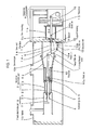
- FIGS. 1 and 2 show a closing state and an opening state of the gas circuit breaker, respectively.
- FIGS. 3 to 5 are partial-enlarged views of a link mechanism assembled in the gas circuit breaker, showing the closing state, an intermediate state between the closing state and the opening state, and the opening state, respectively.
- FIGS. 6 to 10 are graphs for explaining operation and effects of the first embodiment.
- the gas circuit breaker in accordance with the first embodiment includes a container 1 air-tightly filled with an insulating gas, in which a movable electrode part 2 and a fixed electrode part 3 are arranged to face each other and engaging/separating manner.
- the movable electrode part 2 includes a movable arc electrode 2a and a movable main electrode 2b and the fixed electrode part 3 includes a fixed arc electrode 3a and a fixed main electrode 3b. According to an operation of the movable electrode part 2, the movable main electrode 2b is brought in contact with or separated from the fixed main electrode 3b and the movable arc electrode 2a is brought in contact with or separated from the fixed arc electrode 3a.
- a support part 6 is fixed at the inner side of a partition 1a of the container 1 (at a side under the insulating gas atmosphere).
- An insulator 6a for electrical insulation is provided in a portion of the support part 6.
- a mechanism support 1b is fixed at the outer side of the partition 1a of the container 1 (at a side filled with the air).
- a seal bearing 1c having a gas seal function is provided in the partition 1a of the container 1.
- An operating mechanism 8 is disposed on the mechanism support 1b of the container 1.
- the operating mechanism 8 is a mechanism to operate the movable electrode part 2 by providing an operating force to the movable electrode part 2.
- An elastic body such as a spring or the like, or hydraulic system is used as the operating mechanism 8.
- the operating mechanism 8 includes a rotatable output part 16 to output the operating force.
- the movable electrode part 2 is riveted with an insulating nozzle 4 and includes a pressurizing chamber 7 to pressurize the insulating gas.
- the pressurizing chamber 7 is configured to blow out the insulating gas from between the movable arc electrode 2a and the insulating nozzle 4 according to an opening operation by compressing the internal insulating gas.
- the gas circuit breaker according to the first embodiment includes two rods 5 and 14, three links 10, 12 and 15, and an amplification lever 11 to amplify a displacement, all of which are members configured to transfer the operating force of the operating mechanism 8 to the movable electrode part 2. These members are interconnected by six pins 10a, 10b, 12a, 12b, 14a and 14b.
- the rods, the lever and the links are arranged in a direction from the movable electrode part 2 side toward the operating mechanism 8 side in order of the operating rod 5, the first link 10, the amplification lever 11, the second link 12, the seal rod 14 and the third link 15.
- an end near the movable electrode part 2 is referred to as a "front end” and an end near the operating mechanism 8 is referred to as a "rear end”.
- the operating rod 5 is slidably supported by the support part 6 of the partition 1a of the container 1.
- the front end of the operating rod 5 is riveted to the movable electrode part 2.
- the first pin 10a is attached to the rear end of the operating rod 5 and the front end of the first link 10 is rotatably connected through the first pin 10a.
- the second pin 10b is attached to the rear end of the first link 10 and the top of the amplification lever 11 is rotatably connected through the second pin 10b. That is, the first pin 10a and the second pin 10b are respectively attached to both ends of the first link 10. Further, the operating rod 5 and the first link 10 are interconnected by the first pin 10a, and the first link 10 and the amplification lever 11 are interconnected by the second pin 10b.
- the third pin 12a is attached to the bottom of the amplification lever 11, and the front end of the second link 12 is rotatably connected through the third pin 12a.
- the fourth pin 12b is attached to the rear end of the second link 12, and the support bearing 13 is connected by the fourth pin 12b.
- the support bearing 13 is a member to support the second link 12 and is fixed to the inner side of the partition 1a of the container 1, with an insulating spacer 9 interposed therebetween.
- the second link 12 includes the third pin 12a and the fourth pin 12b, which are respectively attached to both ends of the second link 12. Further, the amplification lever 11 and the second link 12 are interconnected by the third pin 12a, and the second link 12 and the support bearing 13 are interconnected by the fourth pin 12b.
- the fifth pin 14a is attached to the substantial center of the amplification lever 11. Accordingly, three pins 10b, 12a and 14a are attached to the amplification lever 11, connected with the first link by the second pin 10b, connected with the second link 12 by the third pin 12a, and rotatably connected with the front end of the seal rod 14 by the fifth pin 14a.
- the front end of the third link 15 is rotatably connected to the rear end of the seal rod 14 through the sixth pin 14b. That is, the fifth pin 14a and the sixth pin 14b are respectively attached to both ends of the seal rod 14. Further, the amplification lever 11 is connected by the fifth pin 14a, and third link 15 is connected by the sixth pin 14b.
- the seal rod 14 is slidably connected to the center of the seal bearing 1c in the partition 1a of the container.
- the output part 16 of the operating mechanism 8 is connected to the rear end of the third link 15.
- a positional relationship between the first link 10, the amplification lever 11 and the seal rod 14 will be now described with reference to FIGS. 1 to 5 .
- a straight line connecting the centers of the second pin 10b and first pin 10a (shown in FIGS. 1 and 2 ) engaged with the first link 10 is defined as a first straight line 10c (shown in FIG 3 ).
- the first straight line 10c and an operating axial line 14c extending in a sliding direction of the seal rod 14 are set to be substantially in parallel or intersect at the seal rod 14 side when viewed from the amplification lever 11, as shown in FIG. 3 .
- the second link 12, the amplification lever 11 and the seal rod 14 are configured to have the following positional relationship with one another.
- a straight line connecting the centers of the fourth pin 12b and third pin 12a included in the second link 12 is defined as a second straight line 12c.
- An angle made between the second straight line 12c on the second link 12 and the operating axial line 14c of the seal rod 14 in the closing state is defined as a support link initial angle ⁇ .
- the support link initial angle ⁇ has a positive value for left rotation with respect to a straight line in parallel to the operating axial line 14c.
- the first link 10, the second link 12, the amplification lever 11 and the seal rod 14 satisfy the above positional relationship, and the support link initial angle ⁇ is set to a range of -2 degrees to 0 degrees. The reason for setting the support link initial angle to this range will be described in detail later with reference to graphs of FIGS. 6 to 10 .
- the seal rod 14 connected to the third link 15 is also moved in the arrow A direction and the amplification lever 11 connected to the seal rod 14 is clockwise rotated around the third pin 12a.
- the first link 10 connected to the amplification lever 11 is moved in the arrow A direction, and the operating rod 5 and the movable electrode part 2 connected thereto are also moved in the arrow A direction.
- the movable electrode part 2 is separated from the fixed electrode part 3 through the above-described movement process.
- the operation of the neighborhood of the amplification lever 11 transitions from the closing state shown in FIG. 3 to the opening state shown in FIG. 5 via an intermediate position shown in FIG. 4 .
- the output part 16 of the operating mechanism 8 has completed the movement of the third link 15 by a predetermined distance, such movement of the third link 15 is also transferred to the movable electrode part 2, thereby completing the opening operation.
- a ratio between the displacement of the seal rod 14 and the displacement of the operating rod 5 is in proportion to a ratio between a distance between the third pin 12a and the fifth pin 14a and a distance between the third pin 12a and the second pin 10b.
- an operating force F m of the operating mechanism 8 is exerted in an opening direction indicated by an arrow A, as shown in FIG. 3 .
- an operating force F m is applied to the seal rod 14 via the third link 15
- a force F 3 along the operating axial line 14c of the seal rod 14 and a force F 3y in a direction perpendicular to the operating axial line 14c are exerted on the fifth pin 14a near the center of the amplification lever 11.
- the direction of the operating axial line 14c is represented by an x axis and the perpendicular direction thereof is represented by a y axis.
- a force F 1 resulting from an inertia force of the movable electrode part 2 and a pressure of the insulating gas compressed in the pressurizing chamber 7 is exerted on the second pin 10b attached to the first link 10.
- the first straight line 10c along the first link 10 intersects the operating axial line 14c of the seal rod 14 at the seal rod 14 side when viewed from the amplification lever 11.
- the radius of rotation of the second pin 10b in the case of the amplification lever 11 is rotated around the fifth pin 14a is shorter than the one in the case of the amplification lever 11 is rotated around the third pin 12a.
- the difference of them is the distance between the fifth pin 14a and the third pin 12a.
- a force F 2 along the second straight line 12c is exerted on the third pin 12a attached to the second link 12.
- the second straight line 12c along the second link 12 is substantially in parallel to or intersects the operating axial line 14c of the seal rod 14 at the operating rod 5 side when viewed from the amplification lever 11.
- the second link 12 is infinitesimal shaken in order to absorb a y-axial component of the displacement of the amplification lever 11 caused by the rotation of the amplification lever 11 around the third pin 12a.
- the amplification lever 11 rotates around the fifth pin 14a with the infinitesimal shake. Therefore, the radius of rotation of the third pin 12a is the distance between the fifth pin 14a and the third pin 12a. Because the fifth pin 14a is located in the approximate center of the amplification lever 11, a y-axial component of displacement of the second link 12(the third pin 12a) and a y-axial component of displacement of the first link 10 can be deemed approximately same.
- a displacement of the second link 12 in a vertical direction is reduced even when the amplification lever 11 is shaken.
- a y-axial component F 2y of the force F 2 applied to the second link 12 may be kept small.
- the vertical force F 3y is small accordingly.
- reference numeral 1d denotes a sliding support to the seal rod 14.
- a distance from the center of the fifth pin 14a located in the center of the amplification lever 11 to the sliding support 1d is S
- the support link initial angle ⁇ refers to the angle made between the second straight line 12c and the operating axial line 14c of the seal rod 14 in the closing state
- the direction of the force F 2 along the second straight line 12c is changed by the support link initial angle ⁇ .
- the y-axial component F 2y of the force F 2 is a factor to determine the vertical force F 3y . Accordingly, the size of the support link initial angle ⁇ has an effect on the vertical force F 3y .
- FIG 6 shows results of calculating a stroke of the movable electrode part 2 and the vertical force F 3y in the opening state of the gas circuit breaker over time.
- the support link initial angle ⁇ is set to 0 degrees.
- FIG. 7 is a graph showing results of calculating a stroke of the movable electrode part 2 and the vertical force F 3y in the opening operation over time in a case where the support link initial angle ⁇ is set to -5 degrees.
- the vertical force F 3y is changed from zero to positive at the start of the opening operation, and thereafter, slowly decreases.
- FIG. 8 shows results of calculating a stroke of the movable electrode part 2 and the bending stress ⁇ of the seal rod 14 in the opening operation of the gas circuit breaker.
- the support link initial angle ⁇ is set to 0 degrees.
- FIG 9 shows results of calculating a stroke of the movable electrode part 2 and the bending stress ⁇ of the seal rod in the opening operation in a case where the support link initial angle ⁇ is set to -5 degrees.
- the bending stress ⁇ is changed from zero to positive at the start of the opening operation, and thereafter, slowly decreases.
- the maximum and minimum of the bending stress ⁇ are ⁇ max and ⁇ min , respectively, their smaller absolute values provide a larger strength of the seal rod 14. Accordingly, when the support link initial angle ⁇ is set so that the absolute values of the maximum and minimum of the bending stress ⁇ decrease, the seal rod 14 can achieve high strength, downsizing and weight reduction.
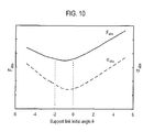
- FIG. 10 shows a relationship between the support link initial angle ⁇ and the sum F abs of absolute values of the maximum (F max ) and minimum (F min ) of the vertical force F 3y .
- FIG. 10 also shows a relationship between the support link initial angle ⁇ and the sum ⁇ abs of absolute values of the maximum ( ⁇ max ) and minimum ( ⁇ min ) of the bending stress ⁇ .
- there exists a support link initial angle ⁇ providing the smallest F abs and ⁇ abs . That is, as shown in the graph of FIG. 10 , the support link initial angle ⁇ in a range of -2 degrees to 0 degrees provides the smallest F abs and ⁇ abs .
- the support link initial angle ⁇ is set to be within the providing the range of -2 degrees to 0 degrees.
- a speed and a force of a movable part (including the movable electrode part 2 and the link mechanism) in the closing operation is generally smaller than those in the opening operation. Accordingly, it is sufficient if strength of each constituent member of the link mechanism is designed with the force generated in the opening operation.
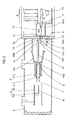
- FIGS. 11 and 12 A puffer type gas circuit breaker in accordance with a second embodiment will be described with reference to FIGS. 11 and 12 .
- FIG 11 is a partial-enlarged view of the gas circuit breaker in a closing state and
- FIG 12 is a side sectional view taken along a direction indicated by an arrow C in FIG 11 .
- the same or similar elements as the first embodiment are denoted by the same reference numerals and explanation of which will not be repeated.
- a guide roller 17 is rotatably attached to the fifth pin 14a of the seal rod 14.
- a guide plate 18 is fixed to the partition 1a and has a long opening 18a formed therein. The longitudinal direction of the long opening 18a is in parallel to the operating axial line 14c.
- the guide roller 17 is slidably inserted in and supported to the long opening 18a.
- the guide roller 17 slidably supporting the seal rod 14 is attached to the fifth pin 14a of the seal rod 14, which eliminates a need to make the entire length of the seal rod 14 large due to such addition of the guide structure.
- the second embodiment employs the guide plate 18 which can be implemented cost-effectively compared to a cylindrical guide member and the like.
- the vertical force F 3y can be also reduced in the second embodiment. Accordingly, there is no need to strengthen the guide plate 18 and the guide roller 17, which can reduce costs and further lead to reduction of the rolling frictional force. As a result, it is possible to reliably prevent the opening speed of the gas circuit breaker from being decreased.
Landscapes
- Driving Mechanisms And Operating Circuits Of Arc-Extinguishing High-Tension Switches (AREA)
- Circuit Breakers (AREA)
Description
- The present disclosure relates to a gas circuit breaker including rods and links to transfer an operating force of an operating mechanism to a movable electrode part.
- A gas circuit breaker of a puffer type or the like is used for a gas-insulated switchgear installed in a substation or a switching station. The gas circuit breaker includes a container air-tightly filled with an insulating gas, in which a fixed electrode part and a movable electrode part are arranged to face each other and engaging/separating manner under the insulating gas atmosphere. The gas circuit breaker further includes an operating mechanism outside the container, i.e., in the air. The operating mechanism refers to a mechanism to operate the movable electrode part by transferring an operating force to the movable electrode part in the container.
- The gas circuit breaker further includes a plurality of rotatable links and linearly movable rods configured to transfer and convert a displacement output, which is an operating force of the operating mechanism, to a displacement of the movable electrode part. In addition, if the displacement output from the operating mechanism is shorter than the displacement of the movable electrode part, a lever to amplify the displacement output from the operating mechanism may be connected to the rods. The connection of the lever to the rods makes it possible to secure a movement stroke of the rods by shaking of the lever.
- An operating rod and a seal rod may be used as a linearly movable rod. The operating rod is a rod configured to provide a driving force to the movable electrode part and may be arranged in its entirety in the container.
- On the other hand, the seal rod is a rod configured to penetrate through a partition of the container and may be slidably attached to a seal bearing (having a gas sealing function) fixed to the partition of the container.
- The conventional gas circuit breaker has the following problems. In this gas circuit breaker, since the combination of rotatable links and linearly movable rods is used to transfer the operating force of the operating mechanism to the movable electrode part, a component force is generated in an operating axial line of the rods in a direction perpendicular to a movement direction of the rods.
- In particular, when the displacement amplification lever is connected to the rods, a large component force is generated since an inertial force of the lever is heavily loaded on the rods. This component force exerts on a portion slidably supporting the rods to increase a frictional force exerted on the rods, which results in a low operating speed of the rods.
- In addition, a bending stress may act on the rods due to the component force, which may result in a deformation of the rods. For the purpose of avoiding such rod deformation, a sectional area (section modulus) of the rods tends to be large. However, such upsizing of the rods increases weight of the rods in proportion, which causes the operating speed of the rods to be lower.
- It is essential to secure a certain level of operating speed of the rods since it has a direct effect on an opening speed of the gas circuit breaker. Accordingly, a large-scaled operating mechanism consuming more driving energy has been conventionally employed in order to secure the operating speed of the rods. However, such large scaling of the operating mechanism leads to increase in costs and size of the entire gas circuit breaker.
-
-
FIG 1 is a sectional view showing a closing state in accordance with a first embodiment. -
FIG 2 is a sectional view showing an opening state in accordance with the first embodiment. -
FIG 3 is a partial-enlarged sectional view ofFIG 1 . -
FIG 4 is a partial-enlarged view showing an intermediate position between the closing state and the opening state. -
FIG 5 is a partial-enlarged sectional view ofFIG 2 . -
FIG 6 is a graph showing results of calculating a stroke of a movable electrode part and a force F3y in the opening state in a case where a support link initial angle θ is set to 0 degrees. -
FIG 7 is a graph showing results of calculating a stroke of a movable electrode part and a force F3y in the opening state in a case where a support link initial angle θ is set to -5 degrees. -
FIG. 8 is a graph showing results of calculating a stroke of a movable electrode part and a bending stress σ of a seal rod in the opening state in a case where a support link initial angle θ is set to 0 degrees. -
FIG. 9 is a graph showing results of calculating a stroke of a movable electrode part and a bending stress σ of a seal rod in the opening state in a case where a support link initial angle θ is set to -5 degrees. -
FIG. 10 is a graph showing a relationship between a support link initial angle θ and the sum Fabs of absolute values of the maximum and minimum of a force F3y. -
FIG. 11 is a partial-enlarged view showing a closing state in accordance with a second embodiment. -
FIG. 12 is a side view ofFIG. 11 . - A puffer type gas circuit breaker in accordance with a first embodiment will be described with reference to
FIGS. 1 to 10 .FIGS. 1 and2 show a closing state and an opening state of the gas circuit breaker, respectively.FIGS. 3 to 5 are partial-enlarged views of a link mechanism assembled in the gas circuit breaker, showing the closing state, an intermediate state between the closing state and the opening state, and the opening state, respectively.FIGS. 6 to 10 are graphs for explaining operation and effects of the first embodiment. - As shown in
FIGS. 1 and2 , the gas circuit breaker in accordance with the first embodiment includes acontainer 1 air-tightly filled with an insulating gas, in which amovable electrode part 2 and afixed electrode part 3 are arranged to face each other and engaging/separating manner. - The
movable electrode part 2 includes a movable arc electrode 2a and a movable main electrode 2b and thefixed electrode part 3 includes a fixed arc electrode 3a and a fixedmain electrode 3b. According to an operation of themovable electrode part 2, the movable main electrode 2b is brought in contact with or separated from the fixedmain electrode 3b and the movable arc electrode 2a is brought in contact with or separated from the fixed arc electrode 3a. - A
support part 6 is fixed at the inner side of apartition 1a of the container 1 (at a side under the insulating gas atmosphere). Aninsulator 6a for electrical insulation is provided in a portion of thesupport part 6. Amechanism support 1b is fixed at the outer side of thepartition 1a of the container 1 (at a side filled with the air). In addition, a seal bearing 1c having a gas seal function is provided in thepartition 1a of thecontainer 1. - An
operating mechanism 8 is disposed on themechanism support 1b of thecontainer 1. Theoperating mechanism 8 is a mechanism to operate themovable electrode part 2 by providing an operating force to themovable electrode part 2. An elastic body such as a spring or the like, or hydraulic system is used as theoperating mechanism 8. Theoperating mechanism 8 includes arotatable output part 16 to output the operating force. - The
movable electrode part 2 is riveted with aninsulating nozzle 4 and includes a pressurizingchamber 7 to pressurize the insulating gas. The pressurizingchamber 7 is configured to blow out the insulating gas from between the movable arc electrode 2a and theinsulating nozzle 4 according to an opening operation by compressing the internal insulating gas. - The gas circuit breaker according to the first embodiment includes two
rods links amplification lever 11 to amplify a displacement, all of which are members configured to transfer the operating force of theoperating mechanism 8 to themovable electrode part 2. These members are interconnected by sixpins - The rods, the lever and the links are arranged in a direction from the
movable electrode part 2 side toward theoperating mechanism 8 side in order of theoperating rod 5, thefirst link 10, theamplification lever 11, thesecond link 12, theseal rod 14 and thethird link 15. In the following description regarding the rods and links included in a link mechanism, an end near themovable electrode part 2 is referred to as a "front end" and an end near theoperating mechanism 8 is referred to as a "rear end". - The
operating rod 5 is slidably supported by thesupport part 6 of thepartition 1a of thecontainer 1. The front end of theoperating rod 5 is riveted to themovable electrode part 2. The first pin 10a is attached to the rear end of theoperating rod 5 and the front end of thefirst link 10 is rotatably connected through the first pin 10a. - The
second pin 10b is attached to the rear end of thefirst link 10 and the top of theamplification lever 11 is rotatably connected through thesecond pin 10b. That is, the first pin 10a and thesecond pin 10b are respectively attached to both ends of thefirst link 10. Further, the operatingrod 5 and thefirst link 10 are interconnected by the first pin 10a, and thefirst link 10 and theamplification lever 11 are interconnected by thesecond pin 10b. - The
third pin 12a is attached to the bottom of theamplification lever 11, and the front end of thesecond link 12 is rotatably connected through thethird pin 12a. Thefourth pin 12b is attached to the rear end of thesecond link 12, and the support bearing 13 is connected by thefourth pin 12b. Thesupport bearing 13 is a member to support thesecond link 12 and is fixed to the inner side of thepartition 1a of thecontainer 1, with an insulatingspacer 9 interposed therebetween. Thesecond link 12 includes thethird pin 12a and thefourth pin 12b, which are respectively attached to both ends of thesecond link 12. Further, theamplification lever 11 and thesecond link 12 are interconnected by thethird pin 12a, and thesecond link 12 and the support bearing 13 are interconnected by thefourth pin 12b. - While the
second pin 10b and thethird pin 12a are respectively attached to the top and bottom of theamplification lever 11 as described above, thefifth pin 14a is attached to the substantial center of theamplification lever 11. Accordingly, threepins amplification lever 11, connected with the first link by thesecond pin 10b, connected with thesecond link 12 by thethird pin 12a, and rotatably connected with the front end of theseal rod 14 by thefifth pin 14a. - The front end of the
third link 15 is rotatably connected to the rear end of theseal rod 14 through thesixth pin 14b. That is, thefifth pin 14a and thesixth pin 14b are respectively attached to both ends of theseal rod 14. Further, theamplification lever 11 is connected by thefifth pin 14a, andthird link 15 is connected by thesixth pin 14b. In addition, theseal rod 14 is slidably connected to the center of the seal bearing 1c in thepartition 1a of the container. In addition, theoutput part 16 of theoperating mechanism 8 is connected to the rear end of thethird link 15. - A positional relationship between the
first link 10, theamplification lever 11 and theseal rod 14 will be now described with reference toFIGS. 1 to 5 . A straight line connecting the centers of thesecond pin 10b and first pin 10a (shown inFIGS. 1 and2 ) engaged with thefirst link 10 is defined as a firststraight line 10c (shown inFIG 3 ). When themovable electrode part 2 and the fixedelectrode part 3 are in the closing state, the firststraight line 10c and an operatingaxial line 14c extending in a sliding direction of theseal rod 14 are set to be substantially in parallel or intersect at theseal rod 14 side when viewed from theamplification lever 11, as shown inFIG. 3 . - The
second link 12, theamplification lever 11 and theseal rod 14 are configured to have the following positional relationship with one another. As shown inFIGS. 3 to 5 , a straight line connecting the centers of thefourth pin 12b andthird pin 12a included in thesecond link 12 is defined as a secondstraight line 12c. When themovable electrode part 2 and the fixedelectrode part 3 are in the closing state, the secondstraight line 12c and the operatingaxial line 14c of theseal rod 14 are set to be substantially in parallel or intersect at the operatingrod 5 side when viewed from theamplification lever 11. - An angle made between the second
straight line 12c on thesecond link 12 and the operatingaxial line 14c of theseal rod 14 in the closing state is defined as a support link initial angle θ. The support link initial angle θ has a positive value for left rotation with respect to a straight line in parallel to the operatingaxial line 14c. In the first embodiment, thefirst link 10, thesecond link 12, theamplification lever 11 and theseal rod 14 satisfy the above positional relationship, and the support link initial angle θ is set to a range of -2 degrees to 0 degrees. The reason for setting the support link initial angle to this range will be described in detail later with reference to graphs ofFIGS. 6 to 10 . - For the opening operation in the first embodiment, a process from the closing state shown in
FIG. 1 to the opening state shown inFIG. 2 will be described below. In the closing state shown inFIG. 1 , when theoperating mechanism 8 receives an opening command from the external, theoutput part 16 is rotated to move thethird link 15 connected to theoutput part 16 in a direction indicated by an arrow A. - The
seal rod 14 connected to thethird link 15 is also moved in the arrow A direction and theamplification lever 11 connected to theseal rod 14 is clockwise rotated around thethird pin 12a. As theamplification lever 11 is rotated, thefirst link 10 connected to theamplification lever 11 is moved in the arrow A direction, and the operatingrod 5 and themovable electrode part 2 connected thereto are also moved in the arrow A direction. Themovable electrode part 2 is separated from the fixedelectrode part 3 through the above-described movement process. - The operation of the neighborhood of the
amplification lever 11 transitions from the closing state shown inFIG. 3 to the opening state shown inFIG. 5 via an intermediate position shown inFIG. 4 . Once theoutput part 16 of theoperating mechanism 8 has completed the movement of thethird link 15 by a predetermined distance, such movement of thethird link 15 is also transferred to themovable electrode part 2, thereby completing the opening operation. In addition, a ratio between the displacement of theseal rod 14 and the displacement of the operatingrod 5 is in proportion to a ratio between a distance between thethird pin 12a and thefifth pin 14a and a distance between thethird pin 12a and thesecond pin 10b. - As a force exerted on each component when the opening operation starts, an operating force Fm of the
operating mechanism 8 is exerted in an opening direction indicated by an arrow A, as shown inFIG. 3 . When the operating force Fm is applied to theseal rod 14 via thethird link 15, a force F3 along the operatingaxial line 14c of theseal rod 14 and a force F3y in a direction perpendicular to the operatingaxial line 14c are exerted on thefifth pin 14a near the center of theamplification lever 11. Here, the direction of the operatingaxial line 14c is represented by an x axis and the perpendicular direction thereof is represented by a y axis. - In addition, in the top of the
amplification lever 11, a force F1 resulting from an inertia force of themovable electrode part 2 and a pressure of the insulating gas compressed in the pressurizingchamber 7 is exerted on thesecond pin 10b attached to thefirst link 10. In the closing state, the firststraight line 10c along thefirst link 10 intersects the operatingaxial line 14c of theseal rod 14 at theseal rod 14 side when viewed from theamplification lever 11. - When the
seal rod 14 moves to the arrow A direction , the linear movement of the seal rod14 is substantially maintained , because the seal rod14 is supported by theseal bearing 1c. In this case, when theamplification lever 11 is rotated around thethird pin 12a, the linear movement of the seal rod14 is restrained. Therefore, when theseal rod 14 moves straight, thefifth pin 14a which connects theamplification lever 11 and theseal rod 14 moves to follow the linear movement of the seal rod14 by the shake of theamplification lever 11 caused by the infinitesimal shake of thesecond link 12. That is, when theseal rod 14 moves to the arrow A direction , theamplification lever 11 is rotated around thefifth pin 14a with the infinitesimal shake. Therefore, the radius of rotation of thesecond pin 10b in the case of theamplification lever 11 is rotated around thefifth pin 14a is shorter than the one in the case of theamplification lever 11 is rotated around thethird pin 12a. The difference of them is the distance between thefifth pin 14a and thethird pin 12a. For these reasons, a y-axial component of the displacement of the first link 10(a y-axial component of the displacement of thesecond pin 10b) is reduced. Accordingly, a y-axial component F1y of the force F1 applied to thefirst link 10 may be kept small. - In addition, in the bottom of the
amplification lever 11, a force F2 along the secondstraight line 12c is exerted on thethird pin 12a attached to thesecond link 12. In the closing state, the secondstraight line 12c along thesecond link 12 is substantially in parallel to or intersects the operatingaxial line 14c of theseal rod 14 at the operatingrod 5 side when viewed from theamplification lever 11. When theseal rod 14 moves to the arrow A direction, the linear movement of the seal rod14 is substantially maintained, because the seal rod14 is supported by theseal bearing 1c. In this case, when theamplification lever 11 is rotated around thethird pin 12a, the linear movement of the seal rod14 is restrained. Therefore, when theseal rod 14 moves straight, thesecond link 12 is infinitesimal shaken in order to absorb a y-axial component of the displacement of theamplification lever 11 caused by the rotation of theamplification lever 11 around thethird pin 12a. As mentioned above, when theseal rod 14 moves to the arrow A direction, theamplification lever 11 rotates around thefifth pin 14a with the infinitesimal shake. Therefore, the radius of rotation of thethird pin 12a is the distance between thefifth pin 14a and thethird pin 12a. Because thefifth pin 14a is located in the approximate center of theamplification lever 11, a y-axial component of displacement of the second link 12(thethird pin 12a) and a y-axial component of displacement of thefirst link 10 can be deemed approximately same. Accordingly, like thefirst link 10, a displacement of thesecond link 12 in a vertical direction is reduced even when theamplification lever 11 is shaken. As a result, a y-axial component F2y of the force F2 applied to thesecond link 12 may be kept small. - The vertical force F3y exerted near the center of the
amplification lever 11 corresponds to the sum of the force F1y exerted on the top of theamplification lever 11 and the force F2y exerted on the bottom of theamplification lever 11, i.e., a relationship of F3y = F1y + F2y is established. In the first embodiment, since both of the forces F1y and F2y are small, the vertical force F3y is small accordingly. - In
FIGS. 3 to 5 ,reference numeral 1d denotes a sliding support to theseal rod 14. Assuming that a distance from the center of thefifth pin 14a located in the center of theamplification lever 11 to the slidingsupport 1d is S, a bending moment M exerted on theseal rod 14 at the slidingsupport 1d can be obtained according to an equation of M = F3y · S. A bending stress σ of theseal rod 14 is accordingly obtained according to an equation of σ = M / Z (where Z is a section modulus of the seal rod 14). - For a frictional force Ff between the seal bearing 1c and the
seal rod 14, assuming that a frictional coefficient is µ, a relationship of Ff = µ · F3y is established. At this time, if the frictional force Ff is large, a resistance in the opening operation is increased, which results in decrease in an opening speed. Thus, in order to make the frictional force Ff small while keeping the frictional coefficient µ constant, it is important to make the vertical force F3y small with respect to the operatingaxial line 14c. - In addition, since the support link initial angle θ refers to the angle made between the second
straight line 12c and the operatingaxial line 14c of theseal rod 14 in the closing state, the direction of the force F2 along the secondstraight line 12c is changed by the support link initial angle θ. The y-axial component F2y of the force F2 is a factor to determine the vertical force F3y. Accordingly, the size of the support link initial angle θ has an effect on the vertical force F3y . - The effect of the support link initial angle θ on the vertical force F3y will be described below with reference to
FIGS. 6 and7 .FIG 6 shows results of calculating a stroke of themovable electrode part 2 and the vertical force F3y in the opening state of the gas circuit breaker over time. Here, the support link initial angle θ is set to 0 degrees. When the opening operation of the gas circuit breaker is started, an absolute value of the vertical force F3y slowly increases from zero and the direction of the vertical force F3y is reversed by an action of a brake (not shown) in theoperating mechanism 8 in the second half of the opening operation. Thereafter, when the opening operation of the gas circuit breaker is completed, the vertical force F3y returns to zero. -
FIG. 7 is a graph showing results of calculating a stroke of themovable electrode part 2 and the vertical force F3y in the opening operation over time in a case where the support link initial angle θ is set to -5 degrees. In comparison withFIG 6 , it can be seen fromFIG. 7 that the vertical force F3y is changed from zero to positive at the start of the opening operation, and thereafter, slowly decreases. - As shown in
FIGS. 6 and7 , assuming that the maximum and minimum of the vertical force F3y are Fmax and Fmin , respectively, their smaller absolute values provide a smaller frictional force Ff of theseal rod 14. Accordingly, when the support link initial angle θ is set so that the frictional force Ff of theseal rod 14 decreases, theseal rod 14 can secure a high operating speed, thereby preventing an opening speed of the gas circuit breaker from decreasing. - In addition, the support link initial angle θ has the effect on the vertical force F3y , which means that it also has an effect on the bending stress σ of the
seal rod 14, as will be described below with reference toFIGS. 8 and9 .FIG. 8 shows results of calculating a stroke of themovable electrode part 2 and the bending stress σ of theseal rod 14 in the opening operation of the gas circuit breaker. Here, the support link initial angle θ is set to 0 degrees. When the opening operation of the gas circuit breaker is started, an absolute value of the bending stress σ slowly increases from zero and the direction of the bending stress σ is reversed by an action of the brake (not shown) in theoperating mechanism 8 in the second half of the opening operation. Thereafter, when the opening operation of the gas circuit breaker is completed, the bending stress σ returns to zero. -
FIG 9 shows results of calculating a stroke of themovable electrode part 2 and the bending stress σ of the seal rod in the opening operation in a case where the support link initial angle θ is set to -5 degrees. As illustrated inFIG 9 in comparison withFIG 8 , the bending stress σ is changed from zero to positive at the start of the opening operation, and thereafter, slowly decreases. Here, as shown inFIG 8 , assuming that the maximum and minimum of the bending stress σ are σ max and σ min , respectively, their smaller absolute values provide a larger strength of theseal rod 14. Accordingly, when the support link initial angle θ is set so that the absolute values of the maximum and minimum of the bending stress σ decrease, theseal rod 14 can achieve high strength, downsizing and weight reduction. -
FIG. 10 shows a relationship between the support link initial angle θ and the sum Fabs of absolute values of the maximum (Fmax) and minimum (Fmin) of the vertical force F3y.FIG. 10 also shows a relationship between the support link initial angle θ and the sum σ abs of absolute values of the maximum (σ max ) and minimum (σ min ) of the bending stress σ. As depicted inFIG. 10 , there exists a support link initial angle θ providing the smallest Fabs and σ abs. That is, as shown in the graph ofFIG. 10 , the support link initial angle θ in a range of -2 degrees to 0 degrees provides the smallest Fabs and σ abs . Accordingly, in the first embodiment, the support link initial angle θ is set to be within the providing the range of -2 degrees to 0 degrees. - The closing operation reaching the closing state shown in
FIG. 1 from the opening state shown inFIG. 2 will be now described. When theoperating mechanism 8 receives a closing command externally in the opening state shown inFIG. 2 , theoutput part 16 is rotated to start movement of thethird link 15 connected to theoutput part 16 in a direction indicated by an arrow B. Theseal rod 14 connected to thethird link 15 is accordingly moved in the direction of arrow B and theamplification lever 11 is counterclockwise rotated around thethird pin 12a. Thefirst link 10 is moved in the direction of arrow B by the rotation of theamplification lever 11 and the operatingrod 5 and themovable electrode part 2 connected thereto are accordingly moved. In this movement process, themovable electrode part 2 is closed to the fixedelectrode part 3. - In addition, in the puffer type gas circuit breaker, a speed and a force of a movable part (including the
movable electrode part 2 and the link mechanism) in the closing operation is generally smaller than those in the opening operation. Accordingly, it is sufficient if strength of each constituent member of the link mechanism is designed with the force generated in the opening operation. - The following is a description on operation and effects of the first embodiment as configured above.
- (1) In the first embodiment, the
second link 12 is fixed to thepartition 1a of thecontainer 1 via thesupport bearing 13. With this configuration, thesecond link 12 and each member connected thereto can achieve improved operability and hence high operation reliability. - (2) The first embodiment can be implemented without a guide or roller to alleviate the bending stress or a case part or the like attached to the guide for the rods which perform the linear operation. Accordingly, the weight of the rods can be reduced and an
operating mechanism 8 consuming less driving energy can be implemented in a compact size. Thus, the gas circuit breaker can be implemented in a compact size as a whole, which reduces the manufacturing cost. - (3) In the first embodiment, the support bearing 13 is attached to the
container 1 via the insulatingspacer 9. This makes it possible to dispose thesecond link 12 attached to the support bearing 13 in close proximity to thecontainer 1. This eliminates a need to secure a large insulating gap between thesecond link 12 and thecontainer 1, which can lead to compactness of thecontainer 1 and hence further compactness of the gas circuit breaker. - (4) Since the operating force from the
operating mechanism 8 is reduced by theamplification lever 11, a large operating force may not be directly exerted on thefirst link 10. This makes it possible to apply an insulating material having a low strength to thefirst link 10 and improve reliability in terms of mechanical strength. - (5) In the first embodiment, the vertical force F3y exerted on the vicinity of the center of the
amplification lever 11 can be reduced, thereby decreasing the frictional force Ff of theseal rod 14 and the bending stress to theseal rod 14. As a result, no deformation occurs even when theseal rod 14 has a small sectional area, which can lead to downsizing and weight reduction of theseal rod 14. This can also lead to an improvement in an operating speed of theseal rod 14. - (6) In addition, in the first embodiment, by setting the support link initial angle θ to a range of -2 degrees to 0 degrees, the frictional force Ff between the seal bearing 1c and the
seal rod 14 can be minimized to obtain a high opening speed. In addition, it is also possible to reduce the bending stress σ exerted on theseal rod 14, which can lead to a high opening speed of the gas circuit breaker. - (7) In addition, in the first embodiment, since the support bearing 13 is fixed to the
partition 1a of thecontainer 1 by thespacer 9, it is possible to easily adjust the support link initial angle θ, which is an angle made between thesecond link 12 and theseal rod 14, by adjusting the thickness of thespacer 9. This can improve the opening speed of the gas circuit breaker. - A puffer type gas circuit breaker in accordance with a second embodiment will be described with reference to
FIGS. 11 and12 .FIG 11 is a partial-enlarged view of the gas circuit breaker in a closing state andFIG 12 is a side sectional view taken along a direction indicated by an arrow C inFIG 11 . The same or similar elements as the first embodiment are denoted by the same reference numerals and explanation of which will not be repeated. - As shown in
FIGS. 11 and12 , aguide roller 17 is rotatably attached to thefifth pin 14a of theseal rod 14. Aguide plate 18 is fixed to thepartition 1a and has along opening 18a formed therein. The longitudinal direction of thelong opening 18a is in parallel to the operatingaxial line 14c. Theguide roller 17 is slidably inserted in and supported to thelong opening 18a. - With the second embodiment as configured above, an opening operation from the closing state shown in
FIG. 11 will be described below. Theguide roller 17 is rotated and moved along thelong opening 18a, while other constituent members have the same movement as those in the opening operation of the first embodiment. At this time, although the vertical force F3y is delivered to thelong opening 18a via theguide roller 17, a reaction having the same size as the vertical force F3y is generated from thelong opening 18a. The closing operation of the second embodiment is similar to that of the first embodiment, which can be easily understood fromFIG. 11 andFIGS. 1 to 5 explained above with respect to the first embodiment, and therefore, explanation thereof will not be repeated. - The second embodiment as configured above has the following operation and effects in addition to the operation and effects of the first embodiment. That is, no bending moment M exerts on the seal rod 14 (i.e., M = 0). Accordingly, the bending stress σ of the
seal rod 14 also becomes zero. Accordingly, there is no need to make the section modulus Z of theseal rod 14 large, which can lead to further downsizing and weight reduction of theseal rod 14. - In addition, in the second embodiment, no vertical force F3y exerts on the
seal bearing 1c. Accordingly, the frictional force Ff becomes substantially zero to prevent the opening speed from being decreased due to increase in the frictional force Ff. Although a frictional force due to contact between theguide roller 17 and thelong opening 18a is generated, a rolling friction coefficient is generally less than 1/100 of a sliding friction coefficient. Accordingly, increase in a frictional force due to the rolling is insignificant and thus have little effect on decrease in the opening speed. - In addition, in the second embodiment, the
guide roller 17 slidably supporting theseal rod 14 is attached to thefifth pin 14a of theseal rod 14, which eliminates a need to make the entire length of theseal rod 14 large due to such addition of the guide structure. In addition, the second embodiment employs theguide plate 18 which can be implemented cost-effectively compared to a cylindrical guide member and the like. - In addition, when the support link initial angle θ described in the first embodiment is appropriately set, the vertical force F3y can be also reduced in the second embodiment. Accordingly, there is no need to strengthen the
guide plate 18 and theguide roller 17, which can reduce costs and further lead to reduction of the rolling frictional force. As a result, it is possible to reliably prevent the opening speed of the gas circuit breaker from being decreased. - While certain embodiments have been described, these embodiments have been presented by way of example only, and are not intended to limit the scope of the disclosures. Indeed, the novel methods and apparatuses described herein may be embodied in a variety of other forms; furthermore, various omissions, substitutions and changes in the form of the embodiments described herein may be made without departing from the spirit of the disclosures. The accompanying claims and their equivalents are intended to cover such forms or modifications as would fall within the scope and spirit of the disclosures. For example, although it has been illustrated in the second embodiment that the
guide roller 17 is guided along thelong opening 18a, thefifth pin 14a may be directly guided along thelong opening 18a.
Claims (9)
- A gas circuit breaker comprising:a movable electrode part and a fixed electrode part which are arranged to face each other and engaging/separating manner in a container air-tightly filled with an insulating gas;an operating mechanism attached to the outer side of a partition of the container and configured to output an operating force from an output part to the movable electrode part;an operating rod including one end attached to the movable electrode part;a first link including one end rotatably attached to the operating rod;a lever including one end rotatably attached to the first link;a support bearing which is fixed to the partition of the container via an insulating spacer;a second link including one end rotatably attached to the lever and the other end rotatably attached to the support bearing;a seal bearing configured to penetrate through the partition of the container;a seal rod which is rotatably attached to the vicinity of the center of the lever and is slidably supported to the seal bearing; anda third link including one end rotatably attached to the seal rod and the other end attached to the output part of the operating mechanism.
- The gas circuit breaker of Claim 1, wherein, when the electrode parts are in a closing state, a central line of the first link along a longitudinal direction intersects an operating axial line of the seal rod at the seal rod side with respect to the lever, and a central line of the second link along a longitudinal direction intersects the operating axial line of the seal rod at the operating rod side with respect to the lever.
- The gas circuit breaker of Claim 1, wherein, when the electrode parts are in a closing state, a central line of the first link along a longitudinal direction intersects an operating axial line of the seal rod at the seal rod side with respect to the lever, and a central line of the second link along a longitudinal direction is substantially in parallel to the operating axial line of the seal rod.
- The gas circuit breaker of Claim 1, wherein a guide plate having a long opening is fixed to the partition, a connection pin is attached to a connection portion of the lever and the seal rod, the connection pin is slidably inserted in the long opening of the guide plate, and the longitudinal direction of the long opening coincides with a direction of linear movement of the seal rod.
- The gas circuit breaker of Claim 4, wherein a guide roller is rotatably attached to the connection pin and is slidably connected to the long opening of the guide plate.
- The gas circuit breaker of Claim 1, wherein the first link is made of an insulating material.
- The gas circuit breaker of Claim 1, wherein an insulating spacer is interposed between the support bearing and the partition of the container.
- The gas circuit breaker of Claim 1, wherein an elastic body is used for a driving source of the operating mechanism.
- The gas circuit breaker of Claim 1, wherein a hydraulic system is used for a driving source of the operating mechanism.
Applications Claiming Priority (2)
| Application Number | Priority Date | Filing Date | Title |
|---|---|---|---|
| JP2011232279 | 2011-10-21 | ||
| PCT/JP2012/006629 WO2013057936A1 (en) | 2011-10-21 | 2012-10-17 | Gas circuit breaker |
Publications (3)
| Publication Number | Publication Date |
|---|---|
| EP2770519A1 true EP2770519A1 (en) | 2014-08-27 |
| EP2770519A4 EP2770519A4 (en) | 2015-07-08 |
| EP2770519B1 EP2770519B1 (en) | 2017-04-26 |
Family
ID=48135113
Family Applications (1)
| Application Number | Title | Priority Date | Filing Date |
|---|---|---|---|
| EP12841501.5A Active EP2770519B1 (en) | 2011-10-21 | 2012-10-17 | Gas circuit breaker |
Country Status (7)
| Country | Link |
|---|---|
| US (1) | US8963039B2 (en) |
| EP (1) | EP2770519B1 (en) |
| JP (1) | JP5735123B2 (en) |
| CN (1) | CN103907168B (en) |
| BR (1) | BR112014009426B1 (en) |
| IN (1) | IN2014DN03043A (en) |
| WO (1) | WO2013057936A1 (en) |
Families Citing this family (6)
| Publication number | Priority date | Publication date | Assignee | Title |
|---|---|---|---|---|
| EP3482408B1 (en) * | 2016-07-06 | 2023-06-07 | Hitachi Energy Switzerland AG | Fast earthing switch device for hv applications |
| DE102016213158A1 (en) | 2016-07-19 | 2018-01-25 | Siemens Aktiengesellschaft | Switchgear arrangement |
| EP3285276B1 (en) * | 2016-08-19 | 2021-09-29 | General Electric Technology GmbH | Drive rod and method of manufacturing a drive rod |
| KR102171601B1 (en) | 2019-01-04 | 2020-10-29 | 효성중공업 주식회사 | Electrode driving apparatus for gas insulated switchgear |
| KR102750160B1 (en) * | 2022-01-25 | 2025-01-07 | 효성중공업 주식회사 | Actuator for gas insulated switchgear |
| US20230420194A1 (en) * | 2022-06-24 | 2023-12-28 | Eaton Intelligent Power Limited | Switch with a movable contact and an elastic assembly |
Family Cites Families (10)
| Publication number | Priority date | Publication date | Assignee | Title |
|---|---|---|---|---|
| JPS58113928U (en) * | 1982-01-29 | 1983-08-04 | 日新電機株式会社 | Roller guide connection mechanism |
| JPH0619937B2 (en) * | 1986-07-14 | 1994-03-16 | 三菱電機株式会社 | Gas circuit breaker coupling device |
| JPH07320611A (en) * | 1994-05-23 | 1995-12-08 | Hitachi Ltd | Gas insulated switchgear |
| JPH0963425A (en) * | 1995-08-21 | 1997-03-07 | Mitsubishi Electric Corp | Gas insulated switch |
| JP3538274B2 (en) * | 1996-01-09 | 2004-06-14 | ティーエム・ティーアンドディー株式会社 | Switchgear coupling device |
| JP2000003643A (en) * | 1998-06-15 | 2000-01-07 | Mitsubishi Electric Corp | Switchgear |
| FR2821696B1 (en) * | 2001-03-01 | 2003-04-25 | Alstom | HIGH VOLTAGE CIRCUIT BREAKER HAVING A SPRING DRIVE WITH AN ADDITIONAL ENERGY RECOVERY SPRING |
| KR100770099B1 (en) * | 2006-04-17 | 2007-10-24 | 금아유압 주식회사 | Manipulators for gas insulated switchgear |
| JP4881120B2 (en) * | 2006-10-03 | 2012-02-22 | 株式会社東芝 | Switch operating mechanism |
| JP5261198B2 (en) * | 2009-01-06 | 2013-08-14 | 株式会社日立製作所 | Gas circuit breaker |
-
2012
- 2012-10-17 EP EP12841501.5A patent/EP2770519B1/en active Active
- 2012-10-17 CN CN201280051708.9A patent/CN103907168B/en active Active
- 2012-10-17 JP JP2013539530A patent/JP5735123B2/en active Active
- 2012-10-17 IN IN3043DEN2014 patent/IN2014DN03043A/en unknown
- 2012-10-17 WO PCT/JP2012/006629 patent/WO2013057936A1/en not_active Ceased
- 2012-10-17 BR BR112014009426-8A patent/BR112014009426B1/en active IP Right Grant
- 2012-10-18 US US13/654,809 patent/US8963039B2/en active Active
Also Published As
| Publication number | Publication date |
|---|---|
| JPWO2013057936A1 (en) | 2015-04-02 |
| IN2014DN03043A (en) | 2015-05-08 |
| BR112014009426A2 (en) | 2017-04-18 |
| US20130098875A1 (en) | 2013-04-25 |
| CN103907168B (en) | 2016-11-23 |
| BR112014009426B1 (en) | 2021-03-16 |
| WO2013057936A1 (en) | 2013-04-25 |
| EP2770519A4 (en) | 2015-07-08 |
| EP2770519B1 (en) | 2017-04-26 |
| CN103907168A (en) | 2014-07-02 |
| JP5735123B2 (en) | 2015-06-17 |
| US8963039B2 (en) | 2015-02-24 |
Similar Documents
| Publication | Publication Date | Title |
|---|---|---|
| EP2770519B1 (en) | Gas circuit breaker | |
| CN1941244B (en) | Gas circuit breaker for electric power | |
| CN100383906C (en) | Control device for actuating at least two switching devices in a coordinated manner | |
| CN102903567B (en) | Power transmission device for vacuum interrupter and vacuum breaker having the same | |
| CN105453209B (en) | Gas circuit breaker | |
| CN1172340C (en) | Multi-pole electrical switching device with drive mechanism and disconnecting module | |
| CN103177900B (en) | Breaker spring operator and breaker | |
| CN101425422B (en) | Electric power opening and closing device and gas insulation circuit-breaker | |
| US20100078302A1 (en) | Insulating switching rod with a contact pressure arrangement comprising a plurality of helical compression springs wound in opposite senses | |
| US2363360A (en) | Circuit interrupter | |
| US11942289B2 (en) | Vacuum interrupter and vacuum breaker | |
| US8878088B2 (en) | Modular MOC driver and interlock assembly for circuit breaker | |
| JP2004281175A (en) | Gas circuit breaker | |
| US10199188B2 (en) | Gas circuit breaker | |
| CN110249403A (en) | Medium voltage switchgear equipment | |
| EP2075813B1 (en) | Spring arrangement for spring drive unit and spring drive unit comprising spring arrangement | |
| US20230160416A1 (en) | Opening/closing device | |
| KR20160003828U (en) | Vacuum circuit breaker | |
| CN107924784B (en) | Opening speed adjustment mechanism and switch device | |
| CN101377984A (en) | Gas circuit breaker | |
| US20240096573A1 (en) | Vacuum circuit breaker | |
| JP2003109476A (en) | Gas circuit breaker | |
| EP4682924A1 (en) | Vacuum circuit breaker | |
| JP2018181502A (en) | Gas circuit breaker | |
| JPS5923335Y2 (en) | Vacuum cutter operating device |
Legal Events
| Date | Code | Title | Description |
|---|---|---|---|
| PUAI | Public reference made under article 153(3) epc to a published international application that has entered the european phase |
Free format text: ORIGINAL CODE: 0009012 |
|
| 17P | Request for examination filed |
Effective date: 20140416 |
|
| AK | Designated contracting states |
Kind code of ref document: A1 Designated state(s): AL AT BE BG CH CY CZ DE DK EE ES FI FR GB GR HR HU IE IS IT LI LT LU LV MC MK MT NL NO PL PT RO RS SE SI SK SM TR |
|
| RIN1 | Information on inventor provided before grant (corrected) |
Inventor name: OHDA, YOSHIAKI Inventor name: SHIMAMURA, AKIRA Inventor name: MARUSHIMA, SATOSHI Inventor name: OCHIAI, RYUSUKE |
|
| DAX | Request for extension of the european patent (deleted) | ||
| RA4 | Supplementary search report drawn up and despatched (corrected) |
Effective date: 20150605 |
|
| RIC1 | Information provided on ipc code assigned before grant |
Ipc: H01H 33/56 20060101ALI20150529BHEP Ipc: H01H 33/91 20060101ALN20150529BHEP Ipc: H01H 33/40 20060101ALN20150529BHEP Ipc: H01H 33/50 20060101ALI20150529BHEP Ipc: H01H 33/30 20060101ALI20150529BHEP Ipc: H01H 33/42 20060101AFI20150529BHEP |
|
| GRAP | Despatch of communication of intention to grant a patent |
Free format text: ORIGINAL CODE: EPIDOSNIGR1 |
|
| STAA | Information on the status of an ep patent application or granted ep patent |
Free format text: STATUS: GRANT OF PATENT IS INTENDED |
|
| RIC1 | Information provided on ipc code assigned before grant |
Ipc: H01H 33/50 20060101ALI20161102BHEP Ipc: H01H 33/56 20060101ALI20161102BHEP Ipc: H01H 33/91 20060101ALN20161102BHEP Ipc: H01H 33/30 20060101ALI20161102BHEP Ipc: H01H 33/42 20060101AFI20161102BHEP Ipc: H01H 33/40 20060101ALN20161102BHEP |
|
| RIC1 | Information provided on ipc code assigned before grant |
Ipc: H01H 33/91 20060101ALN20161110BHEP Ipc: H01H 33/50 20060101ALI20161110BHEP Ipc: H01H 33/30 20060101ALI20161110BHEP Ipc: H01H 33/40 20060101ALN20161110BHEP Ipc: H01H 33/42 20060101AFI20161110BHEP Ipc: H01H 33/56 20060101ALI20161110BHEP |
|
| INTG | Intention to grant announced |
Effective date: 20161207 |
|
| GRAS | Grant fee paid |
Free format text: ORIGINAL CODE: EPIDOSNIGR3 |
|
| GRAA | (expected) grant |
Free format text: ORIGINAL CODE: 0009210 |
|
| STAA | Information on the status of an ep patent application or granted ep patent |
Free format text: STATUS: THE PATENT HAS BEEN GRANTED |
|
| AK | Designated contracting states |
Kind code of ref document: B1 Designated state(s): AL AT BE BG CH CY CZ DE DK EE ES FI FR GB GR HR HU IE IS IT LI LT LU LV MC MK MT NL NO PL PT RO RS SE SI SK SM TR |
|
| REG | Reference to a national code |
Ref country code: GB Ref legal event code: FG4D |
|
| REG | Reference to a national code |
Ref country code: CH Ref legal event code: EP |
|
| REG | Reference to a national code |
Ref country code: AT Ref legal event code: REF Ref document number: 888519 Country of ref document: AT Kind code of ref document: T Effective date: 20170515 |
|
| REG | Reference to a national code |
Ref country code: IE Ref legal event code: FG4D |
|
| REG | Reference to a national code |
Ref country code: DE Ref legal event code: R096 Ref document number: 602012031745 Country of ref document: DE |
|
| REG | Reference to a national code |
Ref country code: NL Ref legal event code: MP Effective date: 20170426 |
|
| REG | Reference to a national code |
Ref country code: LT Ref legal event code: MG4D |
|
| REG | Reference to a national code |
Ref country code: AT Ref legal event code: MK05 Ref document number: 888519 Country of ref document: AT Kind code of ref document: T Effective date: 20170426 |
|
| PG25 | Lapsed in a contracting state [announced via postgrant information from national office to epo] |
Ref country code: NL Free format text: LAPSE BECAUSE OF FAILURE TO SUBMIT A TRANSLATION OF THE DESCRIPTION OR TO PAY THE FEE WITHIN THE PRESCRIBED TIME-LIMIT Effective date: 20170426 |
|
| PG25 | Lapsed in a contracting state [announced via postgrant information from national office to epo] |
Ref country code: GR Free format text: LAPSE BECAUSE OF FAILURE TO SUBMIT A TRANSLATION OF THE DESCRIPTION OR TO PAY THE FEE WITHIN THE PRESCRIBED TIME-LIMIT Effective date: 20170727 Ref country code: LT Free format text: LAPSE BECAUSE OF FAILURE TO SUBMIT A TRANSLATION OF THE DESCRIPTION OR TO PAY THE FEE WITHIN THE PRESCRIBED TIME-LIMIT Effective date: 20170426 Ref country code: AT Free format text: LAPSE BECAUSE OF FAILURE TO SUBMIT A TRANSLATION OF THE DESCRIPTION OR TO PAY THE FEE WITHIN THE PRESCRIBED TIME-LIMIT Effective date: 20170426 Ref country code: ES Free format text: LAPSE BECAUSE OF FAILURE TO SUBMIT A TRANSLATION OF THE DESCRIPTION OR TO PAY THE FEE WITHIN THE PRESCRIBED TIME-LIMIT Effective date: 20170426 Ref country code: HR Free format text: LAPSE BECAUSE OF FAILURE TO SUBMIT A TRANSLATION OF THE DESCRIPTION OR TO PAY THE FEE WITHIN THE PRESCRIBED TIME-LIMIT Effective date: 20170426 Ref country code: FI Free format text: LAPSE BECAUSE OF FAILURE TO SUBMIT A TRANSLATION OF THE DESCRIPTION OR TO PAY THE FEE WITHIN THE PRESCRIBED TIME-LIMIT Effective date: 20170426 Ref country code: NO Free format text: LAPSE BECAUSE OF FAILURE TO SUBMIT A TRANSLATION OF THE DESCRIPTION OR TO PAY THE FEE WITHIN THE PRESCRIBED TIME-LIMIT Effective date: 20170726 |
|
| PG25 | Lapsed in a contracting state [announced via postgrant information from national office to epo] |
Ref country code: IS Free format text: LAPSE BECAUSE OF FAILURE TO SUBMIT A TRANSLATION OF THE DESCRIPTION OR TO PAY THE FEE WITHIN THE PRESCRIBED TIME-LIMIT Effective date: 20170826 Ref country code: LV Free format text: LAPSE BECAUSE OF FAILURE TO SUBMIT A TRANSLATION OF THE DESCRIPTION OR TO PAY THE FEE WITHIN THE PRESCRIBED TIME-LIMIT Effective date: 20170426 Ref country code: BG Free format text: LAPSE BECAUSE OF FAILURE TO SUBMIT A TRANSLATION OF THE DESCRIPTION OR TO PAY THE FEE WITHIN THE PRESCRIBED TIME-LIMIT Effective date: 20170726 Ref country code: RS Free format text: LAPSE BECAUSE OF FAILURE TO SUBMIT A TRANSLATION OF THE DESCRIPTION OR TO PAY THE FEE WITHIN THE PRESCRIBED TIME-LIMIT Effective date: 20170426 Ref country code: PL Free format text: LAPSE BECAUSE OF FAILURE TO SUBMIT A TRANSLATION OF THE DESCRIPTION OR TO PAY THE FEE WITHIN THE PRESCRIBED TIME-LIMIT Effective date: 20170426 Ref country code: SE Free format text: LAPSE BECAUSE OF FAILURE TO SUBMIT A TRANSLATION OF THE DESCRIPTION OR TO PAY THE FEE WITHIN THE PRESCRIBED TIME-LIMIT Effective date: 20170426 |
|
| REG | Reference to a national code |
Ref country code: DE Ref legal event code: R097 Ref document number: 602012031745 Country of ref document: DE |
|
| PG25 | Lapsed in a contracting state [announced via postgrant information from national office to epo] |
Ref country code: DK Free format text: LAPSE BECAUSE OF FAILURE TO SUBMIT A TRANSLATION OF THE DESCRIPTION OR TO PAY THE FEE WITHIN THE PRESCRIBED TIME-LIMIT Effective date: 20170426 Ref country code: EE Free format text: LAPSE BECAUSE OF FAILURE TO SUBMIT A TRANSLATION OF THE DESCRIPTION OR TO PAY THE FEE WITHIN THE PRESCRIBED TIME-LIMIT Effective date: 20170426 Ref country code: RO Free format text: LAPSE BECAUSE OF FAILURE TO SUBMIT A TRANSLATION OF THE DESCRIPTION OR TO PAY THE FEE WITHIN THE PRESCRIBED TIME-LIMIT Effective date: 20170426 Ref country code: CZ Free format text: LAPSE BECAUSE OF FAILURE TO SUBMIT A TRANSLATION OF THE DESCRIPTION OR TO PAY THE FEE WITHIN THE PRESCRIBED TIME-LIMIT Effective date: 20170426 Ref country code: SK Free format text: LAPSE BECAUSE OF FAILURE TO SUBMIT A TRANSLATION OF THE DESCRIPTION OR TO PAY THE FEE WITHIN THE PRESCRIBED TIME-LIMIT Effective date: 20170426 |
|
| PG25 | Lapsed in a contracting state [announced via postgrant information from national office to epo] |
Ref country code: SM Free format text: LAPSE BECAUSE OF FAILURE TO SUBMIT A TRANSLATION OF THE DESCRIPTION OR TO PAY THE FEE WITHIN THE PRESCRIBED TIME-LIMIT Effective date: 20170426 |
|
| PLBE | No opposition filed within time limit |
Free format text: ORIGINAL CODE: 0009261 |
|
| STAA | Information on the status of an ep patent application or granted ep patent |
Free format text: STATUS: NO OPPOSITION FILED WITHIN TIME LIMIT |
|
| 26N | No opposition filed |
Effective date: 20180129 |
|
| REG | Reference to a national code |
Ref country code: DE Ref legal event code: R119 Ref document number: 602012031745 Country of ref document: DE |
|
| PG25 | Lapsed in a contracting state [announced via postgrant information from national office to epo] |
Ref country code: MC Free format text: LAPSE BECAUSE OF FAILURE TO SUBMIT A TRANSLATION OF THE DESCRIPTION OR TO PAY THE FEE WITHIN THE PRESCRIBED TIME-LIMIT Effective date: 20170426 Ref country code: SI Free format text: LAPSE BECAUSE OF FAILURE TO SUBMIT A TRANSLATION OF THE DESCRIPTION OR TO PAY THE FEE WITHIN THE PRESCRIBED TIME-LIMIT Effective date: 20170426 |
|
| REG | Reference to a national code |
Ref country code: CH Ref legal event code: PL |
|
| GBPC | Gb: european patent ceased through non-payment of renewal fee |
Effective date: 20171017 |
|
| REG | Reference to a national code |
Ref country code: IE Ref legal event code: MM4A |
|
| REG | Reference to a national code |
Ref country code: FR Ref legal event code: ST Effective date: 20180629 |
|
| PG25 | Lapsed in a contracting state [announced via postgrant information from national office to epo] |
Ref country code: DE Free format text: LAPSE BECAUSE OF NON-PAYMENT OF DUE FEES Effective date: 20180501 Ref country code: GB Free format text: LAPSE BECAUSE OF NON-PAYMENT OF DUE FEES Effective date: 20171017 Ref country code: CH Free format text: LAPSE BECAUSE OF NON-PAYMENT OF DUE FEES Effective date: 20171031 Ref country code: LI Free format text: LAPSE BECAUSE OF NON-PAYMENT OF DUE FEES Effective date: 20171031 Ref country code: LU Free format text: LAPSE BECAUSE OF NON-PAYMENT OF DUE FEES Effective date: 20171017 |
|
| REG | Reference to a national code |
Ref country code: BE Ref legal event code: MM Effective date: 20171031 |
|
| PG25 | Lapsed in a contracting state [announced via postgrant information from national office to epo] |
Ref country code: FR Free format text: LAPSE BECAUSE OF NON-PAYMENT OF DUE FEES Effective date: 20171031 Ref country code: BE Free format text: LAPSE BECAUSE OF NON-PAYMENT OF DUE FEES Effective date: 20171031 |
|
| PG25 | Lapsed in a contracting state [announced via postgrant information from national office to epo] |
Ref country code: MT Free format text: LAPSE BECAUSE OF NON-PAYMENT OF DUE FEES Effective date: 20171017 |
|
| PG25 | Lapsed in a contracting state [announced via postgrant information from national office to epo] |
Ref country code: IE Free format text: LAPSE BECAUSE OF NON-PAYMENT OF DUE FEES Effective date: 20171017 |
|
| PG25 | Lapsed in a contracting state [announced via postgrant information from national office to epo] |
Ref country code: HU Free format text: LAPSE BECAUSE OF FAILURE TO SUBMIT A TRANSLATION OF THE DESCRIPTION OR TO PAY THE FEE WITHIN THE PRESCRIBED TIME-LIMIT; INVALID AB INITIO Effective date: 20121017 |
|
| PG25 | Lapsed in a contracting state [announced via postgrant information from national office to epo] |
Ref country code: CY Free format text: LAPSE BECAUSE OF NON-PAYMENT OF DUE FEES Effective date: 20170426 |
|
| PG25 | Lapsed in a contracting state [announced via postgrant information from national office to epo] |
Ref country code: MK Free format text: LAPSE BECAUSE OF FAILURE TO SUBMIT A TRANSLATION OF THE DESCRIPTION OR TO PAY THE FEE WITHIN THE PRESCRIBED TIME-LIMIT Effective date: 20170426 |
|
| PG25 | Lapsed in a contracting state [announced via postgrant information from national office to epo] |
Ref country code: TR Free format text: LAPSE BECAUSE OF FAILURE TO SUBMIT A TRANSLATION OF THE DESCRIPTION OR TO PAY THE FEE WITHIN THE PRESCRIBED TIME-LIMIT Effective date: 20170426 |
|
| PG25 | Lapsed in a contracting state [announced via postgrant information from national office to epo] |
Ref country code: PT Free format text: LAPSE BECAUSE OF FAILURE TO SUBMIT A TRANSLATION OF THE DESCRIPTION OR TO PAY THE FEE WITHIN THE PRESCRIBED TIME-LIMIT Effective date: 20170426 |
|
| PG25 | Lapsed in a contracting state [announced via postgrant information from national office to epo] |
Ref country code: AL Free format text: LAPSE BECAUSE OF FAILURE TO SUBMIT A TRANSLATION OF THE DESCRIPTION OR TO PAY THE FEE WITHIN THE PRESCRIBED TIME-LIMIT Effective date: 20170426 |
|
| PGFP | Annual fee paid to national office [announced via postgrant information from national office to epo] |
Ref country code: IT Payment date: 20250922 Year of fee payment: 14 |