EP2770509A1 - Foundation structure for reactor containment vessel - Google Patents
Foundation structure for reactor containment vessel Download PDFInfo
- Publication number
- EP2770509A1 EP2770509A1 EP12840997.6A EP12840997A EP2770509A1 EP 2770509 A1 EP2770509 A1 EP 2770509A1 EP 12840997 A EP12840997 A EP 12840997A EP 2770509 A1 EP2770509 A1 EP 2770509A1
- Authority
- EP
- European Patent Office
- Prior art keywords
- foundation plate
- containment vessel
- reactor containment
- upper foundation
- plate
- Prior art date
- Legal status (The legal status is an assumption and is not a legal conclusion. Google has not performed a legal analysis and makes no representation as to the accuracy of the status listed.)
- Withdrawn
Links
- 238000002955 isolation Methods 0.000 claims abstract description 54
- 210000002435 tendon Anatomy 0.000 claims abstract description 38
- 229910000831 Steel Inorganic materials 0.000 claims description 18
- 239000010959 steel Substances 0.000 claims description 18
- 239000004567 concrete Substances 0.000 claims description 15
- 230000003014 reinforcing effect Effects 0.000 claims description 14
- 239000011150 reinforced concrete Substances 0.000 claims description 10
- 239000011513 prestressed concrete Substances 0.000 claims description 6
- 238000010276 construction Methods 0.000 abstract description 14
- XLYOFNOQVPJJNP-UHFFFAOYSA-N water Substances O XLYOFNOQVPJJNP-UHFFFAOYSA-N 0.000 description 24
- 239000000498 cooling water Substances 0.000 description 19
- 238000010586 diagram Methods 0.000 description 12
- 239000000463 material Substances 0.000 description 6
- 238000003466 welding Methods 0.000 description 4
- 230000005611 electricity Effects 0.000 description 3
- 238000009835 boiling Methods 0.000 description 2
- 239000002826 coolant Substances 0.000 description 2
- 239000003351 stiffener Substances 0.000 description 2
- 229910052770 Uranium Inorganic materials 0.000 description 1
- 238000001816 cooling Methods 0.000 description 1
- 230000000694 effects Effects 0.000 description 1
- 239000000446 fuel Substances 0.000 description 1
- 239000003112 inhibitor Substances 0.000 description 1
- JEIPFZHSYJVQDO-UHFFFAOYSA-N iron(III) oxide Inorganic materials O=[Fe]O[Fe]=O JEIPFZHSYJVQDO-UHFFFAOYSA-N 0.000 description 1
- 238000000034 method Methods 0.000 description 1
- 239000011435 rock Substances 0.000 description 1
- 239000013535 sea water Substances 0.000 description 1
- 230000008719 thickening Effects 0.000 description 1
- JFALSRSLKYAFGM-UHFFFAOYSA-N uranium(0) Chemical compound [U] JFALSRSLKYAFGM-UHFFFAOYSA-N 0.000 description 1
Images



Classifications
-
- G—PHYSICS
- G21—NUCLEAR PHYSICS; NUCLEAR ENGINEERING
- G21C—NUCLEAR REACTORS
- G21C13/00—Pressure vessels; Containment vessels; Containment in general
- G21C13/02—Details
- G21C13/024—Supporting constructions for pressure vessels or containment vessels
-
- E—FIXED CONSTRUCTIONS
- E04—BUILDING
- E04H—BUILDINGS OR LIKE STRUCTURES FOR PARTICULAR PURPOSES; SWIMMING OR SPLASH BATHS OR POOLS; MASTS; FENCING; TENTS OR CANOPIES, IN GENERAL
- E04H5/00—Buildings or groups of buildings for industrial or agricultural purposes
- E04H5/02—Buildings or groups of buildings for industrial purposes, e.g. for power-plants or factories
-
- E—FIXED CONSTRUCTIONS
- E04—BUILDING
- E04H—BUILDINGS OR LIKE STRUCTURES FOR PARTICULAR PURPOSES; SWIMMING OR SPLASH BATHS OR POOLS; MASTS; FENCING; TENTS OR CANOPIES, IN GENERAL
- E04H9/00—Buildings, groups of buildings or shelters adapted to withstand or provide protection against abnormal external influences, e.g. war-like action, earthquake or extreme climate
- E04H9/02—Buildings, groups of buildings or shelters adapted to withstand or provide protection against abnormal external influences, e.g. war-like action, earthquake or extreme climate withstanding earthquake or sinking of ground
- E04H9/021—Bearing, supporting or connecting constructions specially adapted for such buildings
- E04H9/022—Bearing, supporting or connecting constructions specially adapted for such buildings and comprising laminated structures of alternating elastomeric and rigid layers
-
- G—PHYSICS
- G21—NUCLEAR PHYSICS; NUCLEAR ENGINEERING
- G21D—NUCLEAR POWER PLANT
- G21D1/00—Details of nuclear power plant
-
- G—PHYSICS
- G21—NUCLEAR PHYSICS; NUCLEAR ENGINEERING
- G21C—NUCLEAR REACTORS
- G21C13/00—Pressure vessels; Containment vessels; Containment in general
- G21C13/08—Vessels characterised by the material; Selection of materials for pressure vessels
- G21C13/093—Concrete vessels
- G21C13/0933—Concrete vessels made of prestressed concrete
-
- G—PHYSICS
- G21—NUCLEAR PHYSICS; NUCLEAR ENGINEERING
- G21C—NUCLEAR REACTORS
- G21C13/00—Pressure vessels; Containment vessels; Containment in general
- G21C13/08—Vessels characterised by the material; Selection of materials for pressure vessels
- G21C13/093—Concrete vessels
- G21C13/0933—Concrete vessels made of prestressed concrete
- G21C13/0936—Particulars concerning prestressing devices and cables
-
- Y—GENERAL TAGGING OF NEW TECHNOLOGICAL DEVELOPMENTS; GENERAL TAGGING OF CROSS-SECTIONAL TECHNOLOGIES SPANNING OVER SEVERAL SECTIONS OF THE IPC; TECHNICAL SUBJECTS COVERED BY FORMER USPC CROSS-REFERENCE ART COLLECTIONS [XRACs] AND DIGESTS
- Y02—TECHNOLOGIES OR APPLICATIONS FOR MITIGATION OR ADAPTATION AGAINST CLIMATE CHANGE
- Y02E—REDUCTION OF GREENHOUSE GAS [GHG] EMISSIONS, RELATED TO ENERGY GENERATION, TRANSMISSION OR DISTRIBUTION
- Y02E30/00—Energy generation of nuclear origin
-
- Y—GENERAL TAGGING OF NEW TECHNOLOGICAL DEVELOPMENTS; GENERAL TAGGING OF CROSS-SECTIONAL TECHNOLOGIES SPANNING OVER SEVERAL SECTIONS OF THE IPC; TECHNICAL SUBJECTS COVERED BY FORMER USPC CROSS-REFERENCE ART COLLECTIONS [XRACs] AND DIGESTS
- Y02—TECHNOLOGIES OR APPLICATIONS FOR MITIGATION OR ADAPTATION AGAINST CLIMATE CHANGE
- Y02E—REDUCTION OF GREENHOUSE GAS [GHG] EMISSIONS, RELATED TO ENERGY GENERATION, TRANSMISSION OR DISTRIBUTION
- Y02E30/00—Energy generation of nuclear origin
- Y02E30/30—Nuclear fission reactors
Definitions
- Patent Literature 1 Japanese Laid-open Patent Publication No. 2011-163927
- the reactor containment vessel is composed of a thick quake resisting wall, and the quake resisting wall is fixed to the foundation plate by steel rods such as a number of anchor bolts and steel wires. Since the base isolation device is provided between the upper foundation plate and the lower foundation plate in the foundation plate of the building of the conventional nuclear power plant described above, the quake resisting wall is fixed to the upper foundation plate. Therefore, since space has to be provided to fix anchor bolts or the like and an operator is required to perform a fixing operation inside the foundation plate depending on a structural form, the upper foundation plate has a thick structure. The thickening of the upper foundation plate as described above gives rise to the problems that the structure becomes complicated and a construction cost increases due to an increase in construction period and material amount.
- the foundation structure of the reactor containment vessel wherein the reactor containment vessel is a steel plate concrete containment vessel, and anchors serving as the lower structures are fixed to the lower surface of the upper foundation plate through the upper foundation plate.
- the through-holes 34a and the sheath pipes 51 of the upper foundation plate 34 are shaped to be thickened with taper portions in the middle of the ends, and the sheath pipes 51 are fixed wedgewise.
- the through-holes 34a and the sheath pipes 51 of the upper foundation plate 34 may have the same diameter along the longitudinal direction.
- the plurality of base isolation members 36 is horizontally arranged with a prescribed interval between the upper foundation plate 34 and the lower foundation plate 33 as the base isolation device 35, and the lower structures of the reactor containment vessels 11 are extended through the upper foundation plate 34 to the space S between the respective base isolation members 36 to be fixed. Accordingly, since the lower structures of the reactor containment vessel 11 are extended to the space S between the respective base isolation members 36 to be fixed, it is possible for an operator to perform a fixing operation inside the space S. In addition, the space S is not required inside the upper foundation plate 34 to fix the lower structures of the reactor containment vessel 11, and the thinning of the upper foundation plate 34 is allowed.
- FIG. 6 is a cross-sectional diagram illustrating reinforcing-bar fixing portions in the foundation structure of a reactor containment vessel according to a third embodiment of the present invention. Note that members having the same functions as those of the embodiments described above will be denoted by the same reference signs and their detailed descriptions will be omitted.
- the base isolation device 35 is inserted between the upper foundation plate 34 and the lower foundation plate 33 and the reinforcing bars 76 of the reactor containment vessel 11 are fixed to the lower surface of the upper foundation plate 34 through the upper foundation plate 34, the space S is not required inside the upper foundation plate 34 to fix the lower structures of the reactor containment vessel 11 and the thinning of the upper foundation plate 34 and the simplification of a structure are allowed.
- the space S is not required inside the upper foundation plate 34 to fix the lower structures of the reactor containment vessel 11 and the thinning of the upper foundation plate 34 and the simplification of a structure are allowed.
- With a reduction in construction period and material amount it is possible to reduce a construction cost.
Landscapes
- Engineering & Computer Science (AREA)
- Architecture (AREA)
- Physics & Mathematics (AREA)
- High Energy & Nuclear Physics (AREA)
- General Engineering & Computer Science (AREA)
- Plasma & Fusion (AREA)
- Emergency Management (AREA)
- Structural Engineering (AREA)
- Civil Engineering (AREA)
- Environmental & Geological Engineering (AREA)
- Business, Economics & Management (AREA)
- Foundations (AREA)
- Buildings Adapted To Withstand Abnormal External Influences (AREA)
- Vibration Prevention Devices (AREA)
Abstract
Description
- The present invention relates to the foundation structure of a reactor containment vessel to vertically arrange the reactor containment vessel on a foundation plate on the ground.
- As one of nuclear power plants, a pressurized water reactor has been known. The pressurized water reactor uses light water as a reactor coolant and a neutron moderator to produce high-temperature and high-pressure water that does not come to a boil over an entire primary system, supplies the high-temperature and high-pressure water to a steam generator to generate steam through heat exchange, and supplies the steam to a turbine generator to generate electricity.
- In a nuclear power plant having such a pressurized water reactor, a reactor containment vessel is vertically arranged on a foundation plate laid on the ground, and the foundation plate has a base isolation structure. As a foundation plate having such a base isolation structure, there has been known one described in, for example, Patent Literature 1. In the foundation plate of the building of a nuclear plant described in Patent Literature 1, a base isolation device is provided between a lower foundation plate provided on the ground and an upper foundation plate on which a reactor containment vessel is vertically arranged.
- Patent Literature 1: Japanese Laid-open Patent Publication No.
2011-163927 - In the conventional nuclear power plant described above, the reactor containment vessel is composed of a thick quake resisting wall, and the quake resisting wall is fixed to the foundation plate by steel rods such as a number of anchor bolts and steel wires. Since the base isolation device is provided between the upper foundation plate and the lower foundation plate in the foundation plate of the building of the conventional nuclear power plant described above, the quake resisting wall is fixed to the upper foundation plate. Therefore, since space has to be provided to fix anchor bolts or the like and an operator is required to perform a fixing operation inside the foundation plate depending on a structural form, the upper foundation plate has a thick structure. The thickening of the upper foundation plate as described above gives rise to the problems that the structure becomes complicated and a construction cost increases due to an increase in construction period and material amount.
- The present invention is directed to solve the above problems and has an object of providing the foundation structure of a reactor containment vessel that makes it possible to simplify a structure and reduces a construction cost.
- According to an aspect of the present invention in order to achieve the object, there is provided a foundation structure of a reactor containment vessel, including: a lower foundation plate provided on a ground; an upper foundation plate provided over the lower foundation plate; a base isolation device inserted between the upper foundation plate and the lower foundation plate; and a reactor containment vessel provided on the upper foundation plate, wherein lower structures of the reactor containment vessel are fixed to a lower surface of the upper foundation plate through the upper foundation plate.
- Accordingly, since the base isolation device is inserted between the upper foundation plate and the lower foundation plate and the lower structures of the reactor containment vessel are fixed to the lower surface of the upper foundation plate through the upper foundation plate, space is not required inside the upper foundation plate to fix the lower structures of the reactor containment vessel and the thinning of the upper foundation plate and the simplification of a structure are allowed. In addition, with a reduction in construction period and material amount, it is possible to reduce a construction cost.
- According to an another aspect of the present invention, there is provided the foundation structure of the reactor containment vessel, wherein the base isolation device is configured in such a way that a plurality of base isolation members is horizontally arranged with a prescribed interval between the upper foundation plate and the lower foundation plate, and the lower structures of the reactor containment vessel are extended through the upper foundation plate to space between the respective base isolation members to be fixed.
- Accordingly, since the plurality of base isolation members is horizontally arranged with a prescribed interval between the upper foundation plate and the lower foundation plate and the lower structures of the reactor containment vessel are extended to the space between the respective base isolation devices to be fixed, operation space is not required inside the upper foundation plate to fix the lower structures of the reactor containment vessel and the thinning of the upper foundation plate is allowed.
- According to still another aspect of the present invention, there is provided the foundation structure of the reactor containment vessel, wherein the lower structures of the reactor containment vessel are fixed to the lower surface of the upper foundation plate by bearing plates and fixing tools.
- Accordingly, since the lower structures of the reactor containment vessel are fixed to the lower surface of the upper foundation plate by the bearing plates and the fixing tools, it is possible to firmly fix the lower structures to the upper foundation plate.
- According to still another aspect of the present invention, there is provided the foundation structure of the reactor containment vessel, wherein the reactor containment vessel is a prestressed concrete reactor containment vessel, and ends of tendons serving as the lower structures are fixed to the lower surface of the upper foundation plate through the upper foundation plate.
- Accordingly, since the reactor containment vessel is made of a prestressed concrete reactor containment vessel and the ends of the tendons are fixed to the lower surface of the upper foundation plate, it is possible to improve the strength of the reactor containment vessel and thin the upper foundation plate.
- According to still another aspect of the present invention, there is provided the foundation structure of the reactor containment vessel, wherein the reactor containment vessel is a steel plate concrete containment vessel, and anchors serving as the lower structures are fixed to the lower surface of the upper foundation plate through the upper foundation plate.
- Accordingly, since the reactor containment vessel is made of a steel plate concrete containment vessel and the anchors are fixed to the lower surface of the upper foundation plate, it is possible to easily thin the upper foundation plate.
- According to still another aspect of the present invention, there is provided the foundation structure of the reactor containment vessel, wherein the reactor containment vessel is made of a reinforced concrete reactor containment vessel, and ends of reinforcing bars serving as the lower structures are fixed to the lower surface of the upper foundation plate through the upper foundation plate.
- Accordingly, since the reactor containment vessel is made of a reinforced concrete reactor containment vessel and the ends of the reinforcing bars are fixed to the lower surface of the upper foundation plate, it is possible to easily thin the upper foundation plate.
- According to the foundation structure of the reactor containment vessel of the present invention, since a base isolation device is inserted between an upper foundation plate and a lower foundation plate and the lower structures of the reactor containment vessel are fixed to the lower surface of the upper foundation plate through the upper foundation plate, space is not required inside the upper foundation plate to fix the lower structures of the reactor containment vessel and the thinning of the upper foundation plate and the simplification of a structure are allowed. In addition, with a reduction in construction period and material amount, it is possible to reduce a construction cost.
-
-
FIG. 1 is a schematic configuration diagram illustrating a nuclear power plant to which the foundation structure of a reactor containment vessel according to a first embodiment of the present invention is applied. -
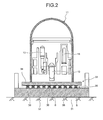
FIG. 2 is a schematic configuration diagram illustrating the foundation structure of the reactor containment vessel of the first embodiment. -
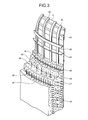
FIG. 3 is a schematic diagram illustrating the wall structure of the prestressed concrete reactor containment vessel of the first embodiment. -
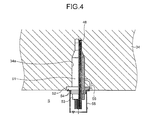
FIG. 4 is a cross-sectional diagram illustrating a tendon fixing portion in the foundation structure of the reactor containment vessel of the first embodiment. -
FIG. 5 is a cross-sectional diagram illustrating anchor fixing portions in the foundation structure of a reactor containment vessel according to a second embodiment of the present invention. -
FIG. 6 is a cross-sectional diagram illustrating reinforcing-bar fixing portions in the foundation structure of a reactor containment vessel according to a third embodiment of the present invention. - Hereinafter, with reference to the accompanying drawings, a description will be given in detail of a preferred embodiment of the foundation structure of a reactor containment vessel according to the present invention. Note that the present invention is not limited to the embodiment but includes, if there is a plurality of embodiments, a combination of the embodiments.
-
FIG. 1 is a schematic configuration diagram illustrating a nuclear power plant to which the foundation structure of a reactor containment vessel according to a first embodiment of the present invention is applied.FIG. 2 is a schematic configuration diagram illustrating the foundation structure of the reactor containment vessel of the first embodiment.FIG. 3 is a schematic diagram illustrating the wall structure of the prestressed concrete reactor containment vessel of the first embodiment.FIG. 4 is a cross-sectional diagram illustrating a tendon fixing portion in the foundation structure of the reactor containment vessel of the first embodiment. - A reactor applied to the nuclear power plant of the first embodiment is made of a pressurized water reactor (PWR: Pressurized Water Reactor) that uses light water as a reactor coolant and a neutron moderator to produce high-temperature and high-pressure water that does not come to a boil over an entire primary system, supplies the high-temperature and high-pressure water to a steam generator to generate steam through heat exchange, and supplies the steam to a turbine generator to generate electricity.
- That is, in the nuclear power plant having the pressurized water reactor, a
reactor containment vessel 11 stores a pressurizedwater reactor 12 and asteam generator 13 as illustrated inFIG. 1 . The pressurizedwater reactor 12 and thesteam generator 13 are connected to each other viacooling water pipes cooling water pipe 14 is provided with apressurizer 16, and thecooling water pipe 15 is provided with acooling water pump 17. In this case, light water is used as a moderator and primary cooling water, and a primary cooling system is controlled by thepressurizer 16 to be kept at a high temperature of about 160 atmospheres to prevent the primary cooling water from coming to a boil in a reactor core portion. Accordingly, the light water serving as the primary cooling water is heated by low-enriched uranium or MOX serving as fuel in the pressurizedwater reactor 12, and the high-temperature primary cooling water is supplied to thesteam generator 13 via thecooling water pipe 14 in a state of being kept at high pressure by thepressurizer 16. The high-pressure and high-temperature primary cooling water is heat-exchanged with secondary cooling water in thesteam generator 13, and the cooled primary cooling water is returned to the pressurizedwater reactor 12 via thecooling water pipe 15. - The
steam generator 13 is connected to aturbine 18 and acondenser 19 provided outside thereactor containment vessel 11 viacooling water pipes cooling water pipe 21 is provided with afeed pump 22. In addition, theturbine 18 is connected to agenerator 23, and thecondenser 19 is connected to anintake pipe 24 and adrain pipe 25 to supply and drain cooling water (for example, seawater). Accordingly, the steam generated by the heat-exchange with the high-pressure and high-temperature primary cooling water in thesteam generator 13 is supplied to theturbine 18 via thecooling water pipe 20, and theturbine 18 is driven by the steam to cause thegenerator 23 to generate electricity. The steam having driven theturbine 18 is cooled by thecondenser 19 and then returned to thesteam generator 13 via thecooling water pipe 21. - As illustrated in
FIG. 2 , thereactor containment vessel 11 of the nuclear power plant thus configured is vertically arranged on afoundation plate 32 laid on ahard ground 31 such as a rock. Further, thereactor containment vessel 11 stores the pressurizedwater reactor 12, thesteam generator 13, thepressurizer 16, and the like described above. - The
reactor containment vessel 11 is made of a reinforced concrete reactor containment vessel (PCCV: Prestressed Concrete Containment Vessel) using prestressed steel wires (called tendons). That is, as illustrated inFIG. 3 , thereactor containment vessel 11 is composed of, from the inside thereof, aliner plate 41,vertical stiffeners 42,horizontal stiffeners 43, reinforcingbars concrete 46,hoop tendons 47,reverse U-shaped tendons 48, and the like. That is, in thereactor containment vessel 11, thehoop tendons 47 and thereverse U-shaped tendons 48 constitute a tendon mechanism that regularly applies a compressive force against inside pressure. - In this case, the
hoop tendons 47 are circumferentially wound inside the wall body of thereactor containment vessel 11, and thereverse U-shaped tendons 48 are axially wound inside the wall body of thereactor containment vessel 11. Therespective hoop tendons 47 are constituted of a bundle of PC steel wires or PC steels and inserted in sheath pipes circumferentially embedded in the wall body of thereactor containment vessel 11 in advance. Further, one or a plurality of buttress portions is circumferentially formed in thereactor containment vessel 11, and the ends of therespective hoop tendons 47 are fixed to the buttress portions. - The respective reverse
U-shaped tendons 48 are constituted of a bundle of PC steel wires or PC steels likewise therespective hoop tendons 47 and inserted in sheath pipes axially embedded in the wall body of thereactor containment vessel 11 in advance. The respective reverseU-shaped tendons 48 are disposed to reticulately cross as viewed from above thereactor containment vessel 11. Further, the ends of the respective reverseU-shaped tendons 48 are fixed to thefoundation plate 32. - Accordingly, the
hoop tendons 47 and the reverseU-shaped tendons 48 are capable of vertically and horizontally shrinking the wall body of thereactor containment vessel 11. Thus, even when starting to expand with an increase in pressure inside thereactor containment vessel 11, thereactor containment vessel 11 may resist the expansion and withstand fluctuations in the inside pressure. - In addition, as illustrated in
FIG. 2 , thefoundation plate 32 is composed of alower foundation plate 33 having a retaining wall on the circumference thereof and disposed on theground 31, anupper foundation plate 34 disposed with a prescribed interval on the upper side in the vertical direction of thelower foundation plate 33, and abase isolation device 35 inserted between thelower foundation plate 33 and theupper foundation plate 34. - The
lower foundation plate 33 has, for example, a reinforced concrete structure (RC structure) incorporating reinforcing bars, is laid on the flatly-developedground 31, and is formed in a square or rectangular shape to have a flat front (upper) surface. Theupper foundation plate 34 has, for example, a reinforced concrete structure (RC structure) incorporating reinforcing bars likewise thelower foundation plate 33 and is formed in a square or rectangular shape to have flat front (upper) and rear (lower) surfaces. - The
base isolation device 35 is provided between the upper surface of thelower foundation plate 33 and the lower surface of theupper foundation plate 34. For example, thebase isolation device 35 is configured in such a way that a plurality ofbase isolation members 36 having a multi-layer base isolation structure in which disc-shaped rubber members and disc-shaped steel plates are alternately laminated together is horizontally arranged with a prescribed interval (preferably with an even interval). Further, the lower side of the respectivebase isolation members 36 is fixed to the upper surface of thelower foundation plate 33, and the upper side thereof is fixed to the lower surface of theupper foundation plate 34. - Further, in the foundation structure of the reactor containment vessel of the first embodiment, the lower structures of the
reactor containment vessel 11 are fixed to the lower surface of theupper foundation plate 34 through theupper foundation plate 34. That is, in thebase isolation device 35 provided between thelower foundation plate 33 and theupper foundation plate 34, the plurality ofbase isolation members 36 is arranged with a prescribed interval, and thus space is secured between the respectivebase isolation members 36. Therefore, the space provided between the respectivebase isolation members 36 is used as operation space to fix the lower structures of thereactor containment vessel 11 to theupper foundation plate 34. Specifically, the lower structures of thereactor containment vessel 11 are extended through theupper foundation plate 34 to the space (operation space) between the respectivebase isolation members 36 to be fixed to the lower surface of theupper foundation plate 34. - Specifically, as illustrated in
FIG. 4 , thefoundation plate 32 is configured in such a way that the plurality ofbase isolation members 36 serving as thebase isolation device 35 is arranged with a prescribed interval between thelower foundation plate 33 and theupper foundation plate 34, and the space (operation space) S is secured between the respectivebase isolation members 36. Since thereactor containment vessel 11 is made of a concrete reactor containment vessel as described above, the reverseU-shaped tendons 48 are applied as the lower structures. The reverseU-shaped tendons 48 are constituted of a bundle of PC steel wires or PC steels and inserted insheath pipes 51 embedded in a wall body 11a of thereactor containment vessel 11. - In the
upper foundation plate 34, through-holes 34a are formed at prescribed positions along a vertical method. The ends of the reverseU-shaped tendons 48 and thesheath pipes 51 are inserted in the through-holes 34a and extended to the space (operation space) S. In addition, bearingplates 52 are fixed to the lower surface of theupper foundation plate 34 at the circumferences of the through-holes 34a, anchor heads 53 serving as fixing tools are fixed to the ends of the reverseU-shaped tendons 48, andshim plates 54 are inserted between the bearingplates 52 and the anchor heads 53. Further, end caps 55 are fixed to the bearingplates 52 to cover the ends of the reverseU-shaped tendons 48, the anchor heads 53, and theshim plates 54, which secures fire protection and fire resistance in the space S of thebase isolation device 35. - In this case, an operator pulls downward the
anchor head 53 fixed to the end of the reverseU-shaped tendon 48 using a jack not illustrated from the space S to apply pressure to the reverseU-shaped tendon 48 in the axial direction of thereactor containment vessel 11. Then, a prescribed number of theshim plates 54 are inserted and fixed between the bearingplate 52 and theanchor head 53 in a state in which the reverseU-shaped tendon 48 is pulled with the prescribed pressure. Afterwards, a rust inhibitor is filled in the reverseU-shaped tendon 48 through a fillingpipe 56 inside the space S. Note that in the fixing operation, the fixing structure is applied to all the reverseU-shaped tendons 48 of thereactor containment vessel 11. - Note that in the first embodiment, the through-
holes 34a and thesheath pipes 51 of theupper foundation plate 34 are shaped to be thickened with taper portions in the middle of the ends, and thesheath pipes 51 are fixed wedgewise. However, without being limited to the shape, the through-holes 34a and thesheath pipes 51 of theupper foundation plate 34 may have the same diameter along the longitudinal direction. - As described above, in the foundation structure of the reactor containment vessel of the first embodiment, the
lower foundation plate 33 provided on theground 31, theupper foundation plate 34 provided over thelower foundation plate 33, thebase isolation device 35 inserted between theupper foundation plate 34 and thelower foundation plate 33, and thereactor containment vessel 11 provided on theupper foundation plate 34 are provided, and the lower structures of thereactor containment vessel 11 are fixed to the lower surface of theupper foundation plate 34 through theupper foundation plate 34. - Accordingly, since the
base isolation device 35 is inserted between theupper foundation plate 34 and thelower foundation plate 33 and the lower structures of thereactor containment vessel 11 are fixed to the lower surface of theupper foundation plate 34 through theupper foundation plate 34, the space S is not required inside theupper foundation plate 34 to fix the lower structures of thereactor containment vessel 11 and the thinning of theupper foundation plate 34 and the simplification of a structure are allowed. In addition, with a reduction in construction period and material amount, it is possible to reduce a construction cost. - In addition, in the foundation structure of the reactor containment vessel of the first embodiment, the plurality of
base isolation members 36 is horizontally arranged with a prescribed interval between theupper foundation plate 34 and thelower foundation plate 33 as thebase isolation device 35, and the lower structures of thereactor containment vessels 11 are extended through theupper foundation plate 34 to the space S between the respectivebase isolation members 36 to be fixed. Accordingly, since the lower structures of thereactor containment vessel 11 are extended to the space S between the respectivebase isolation members 36 to be fixed, it is possible for an operator to perform a fixing operation inside the space S. In addition, the space S is not required inside theupper foundation plate 34 to fix the lower structures of thereactor containment vessel 11, and the thinning of theupper foundation plate 34 is allowed. - Moreover, in the foundation structure of the reactor containment vessel of the first embodiment, the
reactor containment vessel 11 is made of a concrete reactor containment vessel, and the ends of the reverseU-shaped tendons 48 serving as the lower structures are fixed to the lower surface of theupper foundation plate 34 through theupper foundation plate 34. In this case, the ends of the reverseU-shaped tendons 48 are fixed by the bearingplates 52 and the anchor heads 53. Since thereactor containment vessel 11 is made of a concrete reactor containment vessel and the reverseU-shaped tendons 48 are used, it is possible to improve the strength of thereactor containment vessel 11 and firmly fix the reverseU-shaped tendons 48 by the bearingplates 52 and the anchor heads 53. -
FIG. 5 is a cross-sectional diagram illustrating anchor fixing portions in the foundation structure of a reactor containment vessel according to a second embodiment of the present invention. Note that members having the same functions as those of the embodiment described above will be denoted by the same reference signs and their detailed descriptions will be omitted. - A
reactor containment vessel 11 of the second embodiment is made of a steel plate concrete containment vessel (SCCV: Steal Concrete Containment Vessel). That is, as illustrated inFIG. 5 , in thereactor containment vessel 11, awall body 11b is composed ofsteel plates 61,studs 62, tie bars 63, concrete 64, and the like, andbase plates 65 fixed at a lower portion are fixed to afoundation plate 32 byanchors 66. - Further, the
foundation plate 32 is composed of alower foundation plate 33 disposed on aground 31, anupper foundation plate 34 disposed with a prescribed interval on the upper side in the vertical direction of thelower foundation plate 33, and abase isolation device 35 inserted between thelower foundation plate 33 and theupper foundation plate 34, and configured in such a way that a plurality ofbase isolation members 36 is horizontally arranged with a prescribed interval. - That is, the
foundation plate 32 is configured in such a way that the plurality ofbase isolation members 36 serving as thebase isolation device 35 is arranged with a prescribed interval between thelower foundation plate 33 and theupper foundation plate 34, and space (operation space) S is secured between the respectivebase isolation members 36. Since thereactor containment vessel 11 is made of a steel plate concrete containment vessel, theanchors 66 are applied as lower structures. The upper ends of theanchors 66 are fixed to thebase plates 65, and the lower ends thereof are extended through theupper foundation plate 34 to the space (operation space) S. In addition, the bearingplate 67 are fixed to the lower surface of theupper foundation plate 34, and the lower ends of theanchors 66 are fixed to the bearingplates 67 by welding as a fixing means. - In this case, an operator performs an operation to weld the lower ends of the
anchors 66 and the bearingplate 67 together inside the space S. Note that the welding operation is performed at a plurality of places of the lower end of thereactor containment vessel 11 with a prescribed interval in the circumferential direction. - As described above, in the foundation structure of the reactor containment vessel of the second embodiment, the
lower foundation plate 33 provided on theground 31, theupper foundation plate 34 provided over thelower foundation plate 33, thebase isolation device 35 inserted between theupper foundation plate 34 and thelower foundation plate 33, and thereactor containment vessel 11 provided on theupper foundation plate 34 are provided, thereactor containment vessel 11 is made of a steel plate concrete containment vessel, and theanchors 66 serving as the lower structures are extended through theupper foundation plate 34 to the space (operation space) S to be fixed to the bearingplates 67. - Accordingly, since the
base isolation device 35 is inserted between theupper foundation plate 34 and thelower foundation plate 33 and theanchors 66 of thereactor containment vessel 11 are fixed to the lower surface of theupper foundation plate 34 through theupper foundation plate 34, the space S is not required inside theupper foundation plate 34 to fix the lower structures of thereactor containment vessel 11 and the thinning of theupper foundation plate 34 and the simplification of a structure are allowed. In addition, with a reduction in construction period and material amount, it is possible to reduce a construction cost. -
FIG. 6 is a cross-sectional diagram illustrating reinforcing-bar fixing portions in the foundation structure of a reactor containment vessel according to a third embodiment of the present invention. Note that members having the same functions as those of the embodiments described above will be denoted by the same reference signs and their detailed descriptions will be omitted. - A
reactor containment vessel 11 of the third embodiment is made of a reinforced concrete reactor containment vessel (RCCV: Reinforced Concrete Containment Vessel). That is, as illustrated inFIG. 6 , in thereactor containment vessel 11, awall body 11c is composed ofsteel plates 71,studs 72,connection members 73, tie bars 74, concrete 75, and the like, and the lower ends of reinforcingbars 76 having the upper ends thereof embedded in the concrete 75 are fixed to afoundation plate 32. - Further, the
foundation plate 32 is composed of alower foundation plate 33 disposed on aground 31, anupper foundation plate 34 disposed with a prescribed interval on the upper side in the vertical direction of thelower foundation plate 33, and abase isolation device 35 inserted between thelower foundation plate 33 and theupper foundation plate 34, and configured in such a way that a plurality ofbase isolation members 36 is horizontally arranged with a prescribed interval. - That is, the
foundation plate 32 is configured in such a way that the plurality ofbase isolation members 36 serving as thebase isolation device 35 is arranged with a prescribed interval between thelower foundation plate 33 and theupper foundation plate 34, and space (operation space) S is secured between the respectivebase isolation members 36. Since thereactor containment vessel 11 is made of a reinforced concrete reactor containment vessel, the reinforcingbars 76 are applied as lower structures. The upper ends of the reinforcingbars 76 are fixed to the concrete 75 in their embedded state, and the lower ends thereof are extended through theupper foundation plate 34 to the space (operation space) S. In addition, bearingplate 77 are fixed to the lower surface of theupper foundation plate 34, and the lower ends of the reinforcingbars 76 are fixed to the bearingplates 77 by welding as a fixing means. - In this case, an operator performs an operation to weld the lower ends of the reinforcing
bars 76 and the bearingplate 77 together inside the space S. Note that the welding operation is performed at a plurality of places of the lower end of thereactor containment vessel 11 with a prescribed interval in the circumferential direction. - As described above, in the foundation structure of the reactor containment vessel of the third embodiment, the
lower foundation plate 33 provided on theground 31, theupper foundation plate 34 provided over thelower foundation plate 33, thebase isolation device 35 inserted between theupper foundation plate 34 and thelower foundation plate 33, and thereactor containment vessel 11 provided on theupper foundation plate 34 are provided, thereactor containment vessel 11 is made of a reinforced concrete reactor containment vessel, and the reinforcingbars 76 serving as the lower structures are extended through theupper foundation plate 34 to the space (operation space) S to be fixed to the bearingplates 77. - Accordingly, since the
base isolation device 35 is inserted between theupper foundation plate 34 and thelower foundation plate 33 and the reinforcingbars 76 of thereactor containment vessel 11 are fixed to the lower surface of theupper foundation plate 34 through theupper foundation plate 34, the space S is not required inside theupper foundation plate 34 to fix the lower structures of thereactor containment vessel 11 and the thinning of theupper foundation plate 34 and the simplification of a structure are allowed. In addition, with a reduction in construction period and material amount, it is possible to reduce a construction cost. - Note that in each of the embodiments described above, the foundation structure of the reactor containment vessel of the present invention is applied to a pressurized water reactor but may also be applied to a boiling water reactor (BWR: Boiling Water Reactor) and may be applied to any reactor so long as it is a light-water reactor.
-
- 11
- reactor containment vessel
- 12
- pressurized water reactor
- 13
- steam generator
- 31
- ground
- 32
- foundation plate
- 33
- lower foundation plate
- 34
- upper foundation plate
- 35
- base isolation device
- 36
- base isolation member
- 47
- hoop tendon
- 48
- reverse U-shaped tendon (lower structure)
- 51
- sheath pipe
- 52, 67, 77
- bearing plate
- 53
- anchor head (fixing tool)
- 54
- shim plate
- 66
- anchor (lower structure)
- 76
- reinforcing bar (lower structure)
Claims (6)
- A foundation structure of a reactor containment vessel, comprising:a lower foundation plate provided on a ground;an upper foundation plate provided over the lower foundation plate;a base isolation device inserted between the upper foundation plate and the lower foundation plate; anda reactor containment vessel provided on the upper foundation plate, whereinlower structures of the reactor containment vessel are fixed to a lower surface of the upper foundation plate through the upper foundation plate.
- The foundation structure of the reactor containment vessel according to claim 1, wherein
the base isolation device is configured in such a way that a plurality of base isolation members is horizontally arranged with a prescribed interval between the upper foundation plate and the lower foundation plate, and
the lower structures of the reactor containment vessel are extended through the upper foundation plate to space between the respective base isolation members to be fixed. - The foundation structure of the reactor containment vessel according to claim 1 or 2, wherein
the lower structures of the reactor containment vessel are fixed to the lower surface of the upper foundation plate by bearing plates and fixing tools. - The foundation structure of the reactor containment vessel according to any one of claims 1 to 3, wherein
the reactor containment vessel is a prestressed concrete reactor containment vessel, and
ends of tendons serving as the lower structures are fixed to the lower surface of the upper foundation plate through the upper foundation plate. - The foundation structure of the reactor containment vessel according to any one of claims 1 to 3, wherein
the reactor containment vessel is a steel plate concrete containment vessel, and
anchors serving as the lower structures are fixed to the lower surface of the upper foundation plate through the upper foundation plate. - The foundation structure of the reactor containment vessel according to any one of claims 1 to 3, wherein
the reactor containment vessel is a reinforced concrete reactor containment vessel, and
ends of reinforcing bars serving as the lower structures are fixed to the lower surface of the upper foundation plate through the upper foundation plate.
Applications Claiming Priority (2)
| Application Number | Priority Date | Filing Date | Title |
|---|---|---|---|
| JP2011231118A JP5804889B2 (en) | 2011-10-20 | 2011-10-20 | Basic structure of the containment vessel |
| PCT/JP2012/075676 WO2013058113A1 (en) | 2011-10-20 | 2012-10-03 | Foundation structure for reactor containment vessel |
Publications (2)
| Publication Number | Publication Date |
|---|---|
| EP2770509A1 true EP2770509A1 (en) | 2014-08-27 |
| EP2770509A4 EP2770509A4 (en) | 2015-06-17 |
Family
ID=48140765
Family Applications (1)
| Application Number | Title | Priority Date | Filing Date |
|---|---|---|---|
| EP12840997.6A Withdrawn EP2770509A4 (en) | 2011-10-20 | 2012-10-03 | Foundation structure for reactor containment vessel |
Country Status (4)
| Country | Link |
|---|---|
| US (1) | US20140219410A1 (en) |
| EP (1) | EP2770509A4 (en) |
| JP (1) | JP5804889B2 (en) |
| WO (1) | WO2013058113A1 (en) |
Cited By (2)
| Publication number | Priority date | Publication date | Assignee | Title |
|---|---|---|---|---|
| CN105114521A (en) * | 2015-08-26 | 2015-12-02 | 国核电力规划设计研究院 | Nuclear island arrangement structure |
| WO2016092013A1 (en) * | 2014-12-10 | 2016-06-16 | Areva Np | Paraseismic isolation device and assembly comprising a nuclear reactor and the paraseismic isolation device |
Families Citing this family (4)
| Publication number | Priority date | Publication date | Assignee | Title |
|---|---|---|---|---|
| JP6295117B2 (en) * | 2014-03-24 | 2018-03-14 | 大成建設株式会社 | Reactor building |
| GB201907379D0 (en) * | 2019-05-24 | 2019-07-10 | Rolls Royce Plc | A pressure-containing silo for a pressurised water reactor nuclear power plant |
| CN114382829B (en) * | 2022-01-10 | 2023-07-04 | 中广核工程有限公司 | Instrument guide assembly compacting vibration reduction mechanism |
| WO2025144853A1 (en) * | 2023-12-29 | 2025-07-03 | Holtec International | Steam generator enclosure structure for nuclear power generation plant |
Family Cites Families (10)
| Publication number | Priority date | Publication date | Assignee | Title |
|---|---|---|---|---|
| JPS5197698U (en) * | 1975-02-05 | 1976-08-05 | ||
| JPS62162697U (en) * | 1986-04-04 | 1987-10-16 | ||
| FR2603130B1 (en) * | 1986-08-21 | 1988-11-10 | Framatome Sa | RADIATOR FOR NUCLEAR REACTOR CONTAINMENT ENCLOSURE |
| US5490356A (en) * | 1993-11-24 | 1996-02-13 | Mm Systems Of Arizona | Seismic isolation bearing |
| JPH07294682A (en) * | 1994-04-26 | 1995-11-10 | Toshiba Corp | Containment vessel |
| JPH1039078A (en) * | 1996-04-12 | 1998-02-13 | General Electric Co <Ge> | Reactor |
| GB0128820D0 (en) * | 2001-12-01 | 2002-01-23 | Matrice Material Systems Ltd | Fixing cover |
| JP5713552B2 (en) * | 2009-10-30 | 2015-05-07 | 三菱重工業株式会社 | Basic version of building of nuclear facility and construction method of basic version |
| JP5316887B2 (en) * | 2009-12-09 | 2013-10-16 | 清水建設株式会社 | Construction method of seismic isolation building |
| JP5627245B2 (en) | 2010-02-09 | 2014-11-19 | 三菱重工業株式会社 | Basic version of nuclear facility building and nuclear facility |
-
2011
- 2011-10-20 JP JP2011231118A patent/JP5804889B2/en active Active
-
2012
- 2012-10-03 WO PCT/JP2012/075676 patent/WO2013058113A1/en not_active Ceased
- 2012-10-03 US US14/127,593 patent/US20140219410A1/en not_active Abandoned
- 2012-10-03 EP EP12840997.6A patent/EP2770509A4/en not_active Withdrawn
Cited By (3)
| Publication number | Priority date | Publication date | Assignee | Title |
|---|---|---|---|---|
| WO2016092013A1 (en) * | 2014-12-10 | 2016-06-16 | Areva Np | Paraseismic isolation device and assembly comprising a nuclear reactor and the paraseismic isolation device |
| FR3029950A1 (en) * | 2014-12-10 | 2016-06-17 | Areva Np | PARASISMIC ISOLATION DEVICE AND ASSEMBLY COMPRISING A NUCLEAR REACTOR AND THE PARASISMIC INSULATION DEVICE |
| CN105114521A (en) * | 2015-08-26 | 2015-12-02 | 国核电力规划设计研究院 | Nuclear island arrangement structure |
Also Published As
| Publication number | Publication date |
|---|---|
| JP5804889B2 (en) | 2015-11-04 |
| US20140219410A1 (en) | 2014-08-07 |
| JP2013088363A (en) | 2013-05-13 |
| WO2013058113A1 (en) | 2013-04-25 |
| EP2770509A4 (en) | 2015-06-17 |
Similar Documents
| Publication | Publication Date | Title |
|---|---|---|
| US20140219410A1 (en) | Foundation structure of reactor containment vessel | |
| Liu et al. | Technology readiness assessment of small modular reactor (SMR) designs | |
| Alemberti et al. | European lead fast reactor—ELSY | |
| Lee et al. | The concept of the innovative power reactor | |
| Bhardwaj | The future 700áMWe pressurized heavy water reactor | |
| CA1049665A (en) | Nuclear reactor apparatus | |
| Tujikura et al. | Development of passive safety systems for Next Generation PWR in Japan | |
| Schulenberg | Material requirements of the high performance light water reactor | |
| JP2016080359A (en) | Nuclear facility and reinforcement method of nuclear facility outer wall | |
| EP3977486B1 (en) | Pressure-containing silo for a pressurised water reactor nuclear power plant | |
| Forsberg | Goals, requirements, and design implications for the advanced high-temperature reactor | |
| Petrovic et al. | Iris project update: status of the design and licensing activities | |
| Okubo | Small modular reactors (SMRs): The case of Japan | |
| JP2015102394A (en) | Support device of reactor vessel | |
| Southwood | Concrete vessel technology | |
| EP3422361B1 (en) | Turbine building and nuclear power plant | |
| Pieńkowski | Competitiveness Strategies of Key Small Modular Light Water Reactor Projects | |
| Belyaev et al. | Technology Development and Design Approaches Including Economic of Small and Medium Sized Reactor | |
| Campbell | Fukushima nuclear crisis | |
| Lillington et al. | Main Characteristics of Nuclear Power Plants in the European Union and Candidate Countries | |
| ASEA-ATOM | Reactor containment vessel | |
| Iigaki et al. | A safety evaluation of HTTR core graphite structures against the great east japan earthquake | |
| Gou et al. | Containments design for the Advanced and Simplified Boiling Water Reactor standard plants | |
| Caira et al. | MARS II: A design improvement to reduce construction time and cost | |
| Matsuura et al. | Development of next-generation boiling water reactor |
Legal Events
| Date | Code | Title | Description |
|---|---|---|---|
| PUAI | Public reference made under article 153(3) epc to a published international application that has entered the european phase |
Free format text: ORIGINAL CODE: 0009012 |
|
| 17P | Request for examination filed |
Effective date: 20131219 |
|
| AK | Designated contracting states |
Kind code of ref document: A1 Designated state(s): AL AT BE BG CH CY CZ DE DK EE ES FI FR GB GR HR HU IE IS IT LI LT LU LV MC MK MT NL NO PL PT RO RS SE SI SK SM TR |
|
| DAX | Request for extension of the european patent (deleted) | ||
| RA4 | Supplementary search report drawn up and despatched (corrected) |
Effective date: 20150515 |
|
| RIC1 | Information provided on ipc code assigned before grant |
Ipc: G21C 13/024 20060101AFI20150508BHEP Ipc: E04H 5/02 20060101ALI20150508BHEP Ipc: G21D 1/00 20060101ALI20150508BHEP Ipc: E02D 27/34 20060101ALI20150508BHEP Ipc: E02D 27/32 20060101ALI20150508BHEP Ipc: G21C 13/093 20060101ALN20150508BHEP Ipc: E04H 9/02 20060101ALI20150508BHEP |
|
| GRAP | Despatch of communication of intention to grant a patent |
Free format text: ORIGINAL CODE: EPIDOSNIGR1 |
|
| RIC1 | Information provided on ipc code assigned before grant |
Ipc: E04H 9/02 20060101ALI20160804BHEP Ipc: E02D 27/32 20060101ALI20160804BHEP Ipc: G21C 13/024 20060101AFI20160804BHEP Ipc: G21D 1/00 20060101ALI20160804BHEP Ipc: E02D 27/34 20060101ALI20160804BHEP Ipc: G21C 13/093 20060101ALN20160804BHEP Ipc: E04H 5/02 20060101ALI20160804BHEP |
|
| INTG | Intention to grant announced |
Effective date: 20160818 |
|
| RIC1 | Information provided on ipc code assigned before grant |
Ipc: G21D 1/00 20060101ALI20160809BHEP Ipc: E04H 9/02 20060101ALI20160809BHEP Ipc: E02D 27/34 20060101ALI20160809BHEP Ipc: G21C 13/093 20060101ALN20160809BHEP Ipc: E02D 27/32 20060101ALI20160809BHEP Ipc: E04H 5/02 20060101ALI20160809BHEP Ipc: G21C 13/024 20060101AFI20160809BHEP |
|
| STAA | Information on the status of an ep patent application or granted ep patent |
Free format text: STATUS: THE APPLICATION IS DEEMED TO BE WITHDRAWN |
|
| 18D | Application deemed to be withdrawn |
Effective date: 20170103 |