EP2770478A2 - Image processing unit, imaging device, and vehicle control system and program - Google Patents
Image processing unit, imaging device, and vehicle control system and program Download PDFInfo
- Publication number
- EP2770478A2 EP2770478A2 EP14156277.7A EP14156277A EP2770478A2 EP 2770478 A2 EP2770478 A2 EP 2770478A2 EP 14156277 A EP14156277 A EP 14156277A EP 2770478 A2 EP2770478 A2 EP 2770478A2
- Authority
- EP
- European Patent Office
- Prior art keywords
- area
- image
- distortion
- correction
- distortion correction
- Prior art date
- Legal status (The legal status is an assumption and is not a legal conclusion. Google has not performed a legal analysis and makes no representation as to the accuracy of the status listed.)
- Granted
Links
Images




Classifications
-
- G—PHYSICS
- G06—COMPUTING OR CALCULATING; COUNTING
- G06T—IMAGE DATA PROCESSING OR GENERATION, IN GENERAL
- G06T3/00—Geometric image transformations in the plane of the image
- G06T3/18—Image warping, e.g. rearranging pixels individually
-
- G—PHYSICS
- G06—COMPUTING OR CALCULATING; COUNTING
- G06T—IMAGE DATA PROCESSING OR GENERATION, IN GENERAL
- G06T5/00—Image enhancement or restoration
- G06T5/80—Geometric correction
Definitions
- the present invention relates to an image processing unit, an imaging device, and vehicle control system and program applicable to an in-vehicle camera which captures an image of the outside of a vehicle through a front glass element such as windshield.
- Japanese Patent No. 4326999 discloses, as a drive assist, imaging the outside of a vehicle with an in-vehicle camera through a windshield, detecting attached matter such as raindrops on the windshield, and controlling the wiper operation or the ejection of washer liquid of the vehicle based on detected information.
- Reference 1 further describes setting two areas, i.e., attached matter detection area and vehicle forward area in a captured image.
- an optical filter is provided to transmit a light with an infrared wavelength range, for example, to detect attached matter such as raindrops on the windshield.
- an object such as a white line marking ahead of the vehicle is detected.
- the camera includes a lens ahead of an image sensor so that a subject image incident through the lens, such as the raindrops or white line marking ahead of the vehicle, is formed on the image sensor. It is known that due to the optical property of a lens, a distortion occurs in a subject image formed on the image sensor.
- Japanese Patent Application Publication No. 2007-189361 discloses a technique for correcting the distortion of a captured image, for example.
- the entire captured image including the attached matter detection area and vehicle forward area are evenly subjected to the distortion correction. Distortion needs to be accurately corrected in the vehicle forward area to improve the recognition of a target object while distortion does not need to be corrected in the attached matter detection area for detecting raindrops.
- the present invention aims to provide an image processing unit, an imaging device, and vehicle control system and program which can prevent a decrease in the accuracy with which raindrops are detected in an attached matter detection area due to distortion correction.
- an image processing unit comprises a distortion corrector to correct a distortion of an image of a subject formed on an image sensor via an imaging lens in accordance with an optical property of the imaging lens.
- the image sensor has a light-receiving surface including a first area and a second area in which images used for first and second purposes are captured, respectively.
- the distortion corrector is adapted to perform a first distortion correction on an image in the first area, and perform a second distortion correction different from the first distortion correction or perform no distortion correction on an image in the second area.
- FIG. 1 schematically shows the structure of an imaging device incorporating an image processing unit according to one embodiment of the present invention.
- FIG. 2 is a schematic block diagram showing a vehicle control system incorporating the imaging device in FIG. 1 by way of example.
- an imaging device 1 comprises an imaging unit 2 and an image processing unit 3.
- the imaging unit 2 includes an imaging lens 4, an optical filter 5, and an image sensor 7 such as CCD mounted on a substrate 6.
- the optical filter 5 includes an area 5a at the top through which only infrared light in a certain infrared wavelength range is transmitted and another area 5b at the bottom through which light in a visible wavelength range is transmitted.
- Light-receiving elements or pixels are two-dimensionally arranged on the image sensor 7.
- the imaging lens 4 is comprised of plural lenses although only one lens is shown in FIG. 1 .
- the optical filter 5 is disposed to face the front side of the image sensor 7.
- the whole area of an image formed on the image sensor 7 via the imaging lens 4 is divided into a raindrops detection area 8 as a second area and a vehicle forward area 9 as a first area, for example.
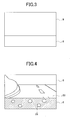
- the raindrops detection area through which infrared light transmits corresponds to the top area 5a while the vehicle forward area 9 through which visible light transmits corresponds to the bottom area 5b, as shown in FIG. 3 .
- the image formed on the image sensor 7 via the imaging lens 4 is an inverted image so that the top area 5a of the optical filter 5 corresponds to the raindrops detection area 8 at the bottom as shown in FIG. 3 .
- the image sensor 7 converts the image into electric signals and outputs them to the image processing unit 3.
- the image processing unit 3 performs known signal processing on the electric signals to generate displayable or storable image data.
- the image processing unit 3 further comprises a distortion corrector 10 to correct a distortion of generated image data by signal processing, which occurs due to the optical property of the lenses of the imaging lens 4.
- the structure of the distortion corrector 10 and distortion correction will be described in detail later.
- a vehicle control system 20 comprises the above-described imaging device 1, a light source 21, a light source controller 22, a raindrops detector 23 as an attached matter detector, a vehicle forward detector 24, an in-vehicle controller (ECU) 25, a wiper controller 26 and a lamp controller 27.
- ECU in-vehicle controller
- the imaging unit 2 of the imaging device 1 images an area ahead of the vehicle through a windshield 28 as a plate element with an optical permeability, and the image processing unit 3 generates an image including the raindrops detection area 8 and vehicle forward area 9 in FIG. 3 .
- the distortion corrector 10 corrects a distortion of the generated image.
- the light source controller 22 controls the light source 21 to project an infrared light beam to the windshield 28 in synchronization with the imaging operation of the imaging device 1.
- the top area 5a of the optical filter 5 functions to selectively transmit a light with an infrared wavelength range among the light beam from the light source 21. Thereby, with raindrops 29 attached on the surface of the windshield 28, the infrared light beam from the light source 21 is reflected by the raindrops and the reflected light is imaged on the image sensor 7 via the imaging lens 4 and the top area 5a of the optical filter 5.
- the imaging unit 2 of the imaging device 1 images a vehicle forward area through the windshield 28 and forms an image on the image sensor 7 via the imaging lens 4 and the bottom area 5b of the optical filter 5.
- FIG. 4 shows an example of an image including a road surface 30 ahead of the vehicle in the vehicle forward area 9 and the raindrops 29 in the raindrops detection area 8 when captured by the imaging device 1 through the windshield 28.
- the infrared light beam is irradiated from the light source 21 to the windshield 28, thereby to be able to properly project the image of the raindrops 29 in the raindrops detection area 8, with an influence from sunlight and streetlights reduced.
- the raindrops detector 23 receives image data in the raindrops detection area 8 from the imaging device 1 or image processing unit 3. Raindrops can be detected in the following manner by way of example.
- the brightness of the entire raindrops detection area 8 differs.
- thresholds of brightness values are acquired by experiment and stored in a memory in advance.
- the raindrops detector 23 is configured to detect an attached raindrop according to the brightness value of image data in the entire raindrops detection area 8. When the brightness value exceeds a threshold, it determines that raindrops are attached on the windshield.
- the vehicle forward detector 24 performs predetermined image processing on the image data in the vehicle forward area 9 input from the imaging device 1 or image processing unit 3 and detects a traffic lane (white line marking) or a preceding vehicle, for example.
- the in-vehicle ECU 25 receives detected raindrops information from the raindrops detector 23 and outputs a signal to the wiper controller 26 in accordance with the raindrops information to operate a not-shown wiper to remove the raindrops from the surface of the windshield 28.
- a washer liquid can be sprayed onto the windshield 28 in replace of the wiper operation.
- the in-vehicle ECU 25 receives vehicle forward information including taillights of a preceding vehicle at night from the vehicle forward detector 24 and outputs a signal to the lamp controller 27 in accordance with the information and controls the switching of the taillights between a high beam and a low beam.
- the in-vehicle ECU 25 can be configured to output a signal to a brake controller to operate the brake when recognizing approaching a preceding vehicle from the vehicle forward information, for example.
- the structure of the distortion corrector 10 is described with reference to FIG. 5 .
- the vehicle forward detector 24 is required to accurately recognize a white line marking or a preceding vehicle ahead of the vehicle so that a distortion of the vehicle forward area 9 of a captured image needs to be accurately corrected.
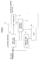
- the distortion corrector 10 in FIG. 5 comprises an image line data buffer 30, a correction area determiner 31, a coordinate calculator 32, a pixel interpolator 33 and a ROM 34 as a storage medium.
- the ROM 34 contains correction target information including a distortion correction parameter for each image area in line with the property of the imaging lens 4, an area ID for each image area, coordinates (X, Y) in the entire effective image area (coordinates of a base point in the top left of each image area) for each area ID, and the width and height of each image area.
- the image line data buffer 30 receives image data and a synchronous signal from the imaging unit 2 and holds a necessary number of lines of pixel data for distortion correction in a ring buffer format. It outputs four neighboring pixel data to the pixel interpolator 33 according to a buffer address designated by the coordinate calculator 32.
- the four neighboring pixels are the pixel designated by the buffer address and three neighboring pixels to the right, below, and obliquely right downward.
- the correction area determiner 31 calculates coordinates of a current image in accordance with a synchronous signal from the imaging unit 2 and compares them with the correction target information from the ROM 34, to determine whether the pixel in question is a target pixel to be distortion-corrected. It then outputs an area ID, a correction valid signal indicating a target or not of distortion correction, and a synchronous signal to the coordinate calculator 32.
- the coordinate calculator 32 then reads a distortion correction parameter from the ROM 34 to calculate coordinates for distortion correction. It calculates pixel coordinates after distortion correction relative to a pixel position before distortion correction as an address of the line data buffer expressed in unit of a pixel (integer value) and a sub-pixel accurate brightness correction amount. Also, it outputs, for each pixel of each image area, an address of the image line data buffer 30 to be a target of correction and a correction amount for calculating a brightness at sub-pixel accuracy, in accordance with the area ID, correction valid signal, and synchronous signal from the correction area determiner 31.
- the coordinate calculator 32 reads the distortion correction parameter from the storage medium and outputs an address, expressed in unit of a pixel, of the image line data buffer specified by the distortion correction parameter and an interpolation value for a distortion correction amount of less than the unit of a pixel based on the address.
- the interpolation value is an X correction amount in a horizontal direction of the image and a Y correction amount in a vertical direction of the image.
- the coordinate calculator 32 designates a pixel data address as a reference to a source pixel to be moved for distortion correction, to control a read of the image line data buffer 30 and outputs an interpolation value to the pixel interpolator 33 as an X correction amount in image horizontal direction and a Y correction amount in image vertical direction.
- the interpolation value is an intermediate value among the four-pixel data and corresponds to a distortion correction amount of less than unit of a pixel.
- the pixel interpolator 33 receives the four-pixel data read from the image line data buffer 30 and the interpolation value from the coordinate calculator 32 to calculate a value of a destination pixel by bilinear interpolation.
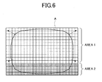
- FIG. 6 shows the entire image area captured by the imaging unit 2, which corresponds to the light-receiving surface of the image sensor 7 on which the pixels are arranged.
- a subject image including a distortion is formed on the light receiving surface.
- an area 1 corresponds to the vehicle forward area 9 as a first area while an area 2 corresponds to the raindrops detection area 8 as a second area.
- An area A surrounded by a broken line is the outermost area of the image in which a distortion occurs.
- the outermost area of an ideal image free from a distortion is located on the outermost pixels of the light receiving surface.
- the arrows in the drawing indicate a direction in which a brightness value is moved by distortion correction. In FIG. 6 distortion correction is performed only on the area 1 corresponding to the vehicle forward area 9.
- FIG. 7 shows the positions of the four source pixels or target pixels to be distortion-corrected and a destination pixel in the top left area of the image area in FIG. 6 , for example. It shows that the brightness value calculated at sub-pixel accuracy is moved from the brightness values of the four source pixels.
- FIG. 8 shows the positions of the four source pixels as a target of correction and the destination pixel in FIG. 7 in detail and the pixel interpolation process of the pixel interpolator 33.
- the pixel interpolator 33 reads the four source-pixel data from the image line data buffer 30 and applies, by bilinear interpolation, the intermediate value thereof to a value of a destination pixel as a sub-pixel correction amount which is the X correction amount in image horizontal direction and the Y correction amount in image vertical direction.
- the interpolation value for the bilinear interpolation of a destination pixel value is calculated in the following manner.
- Pixel value a T - ⁇ Y * A + ⁇ Y * B / T
- the pixel address same as that before distortion correction is read and the X and Y correction amounts of zero are given by the coordinate calculator 32. Thereby, a not-corrected source-pixel value is output.
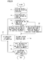
- FIG. 9 the image is divided into the area 1 corresponding to the vehicle forward area 9 and the area 2 corresponding to the raindrops detection area 8 as shown in FIG. 6 . Only the area 1 or vehicle forward area 9 is subjected to the distortion correction.
- step S1 when the distortion corrector 10 starts performing distortion correction the coordinate calculator 32 reads a distortion correction parameter for each image area from the ROM 34 and calculates a default value for calculation of coordinates for distortion correction according to the read parameter.
- step S2 the correction area determiner 31 reads from the ROM 34 the correction target information including coordinates (X, Y) of a base point corresponding to the area 1 or vehicle forward area 9 and the width and height of the image area.
- step S3 the correction area determiner 31 calculates the coordinates of a current image according to the synchronous signal from the imaging unit 2 and compares them with the correction target information read from the ROM 34 to determine whether or not the coordinates or pixel in question is the one to be distortion-corrected. If the coordinates are determined to be a target of distortion correction (YES in step S3), the coordinate calculator 32 calculates a buffer address of correction data and X and Y correction amounts at sub-pixel accuracy in step S4.
- the coordinate calculator 32 With the coordinates determined as not a target of distortion correction (NO in step S3), the coordinate calculator 32 does not calculate a buffer address and the sub-pixel accurate X and Y correction amounts in step S5 when the data in question is not to be corrected.
- step S6 the image line data buffer 30 designates the buffer address to read the four source-pixel data.
- step S7 the pixel interpolator 33 performs the above-described pixel interpolation on the basis of the data read in step S6 and the sub-pixel accurate X and Y correction amounts calculated in step S4.
- a series of distortion correction process is ended.
- a next pixel is set to be a target of distortion correction in step S9 and subjected to the operation in steps S3 to S7.
- an object in the area 1 or vehicle forward area 9 needs to be precisely recognized.
- only the area 1 is subjected to the distortion correction so that it is possible to prevent a part of the area 1 from entering the area 2.
- the brightness signal of an optical component in a wavelength range other than the infrared wavelength range, which should be incident on the area 1 can be prevented from entering a part of the area 2 (raindrops detection area 8) in which the brightness signal of an optical component in the infrared wavelength range is extracted through the top area 5a of the optical filter 5. This makes it possible to stably, accurately detect raindrops and prevent a decrease in the detection accuracy.
- the area 2 is not subjected to the distortion correction as shown in FIG. 6 .
- it can be configured that distortion correction is performed on plural divided areas with respective different correction amounts.
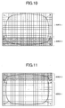
- a captured image include two vertically divided areas 1 and 2 corresponding to the vehicle forward area 9 and raindrops detection area 8, and these divided areas 1 and 2 are subjected to distortion correction at different correction amounts.
- FIG. 11 shows an example of a captured image having the areas 1 and 2 arranged reversely. The area 2 corresponding to the raindrops detection area 8 is placed at top of the image and the area 1 corresponding to the vehicle forward area 9 is placed at bottom. The areas 1 and 2 are subjected to distortion correction with different correction amounts.
- FIG. 12 shows another example of a captured image having three horizontally divided areas, an area 1 at the center corresponding to the vehicle forward area 9 and right and left areas 2a, 2b corresponding to the raindrops detection area 8.
- the areas 1 and 2a and 2b are subjected to distortion correction with different correction amounts.
- the correction amounts applied to the second areas 2a, 2b can be same or different.
- FIG. 13 shows another example of a captured image having an area 1 corresponding to the vehicle forward area 9 and an area 2 corresponding to the raindrops detection area 8 at bottom center.
- the areas 1 and 2 are subjected to distortion correction with different correction amounts.
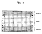
- FIG. 14 shows another example of a captured image having three vertically divided areas, an area 1 at the center corresponding to the vehicle forward area 9 and top and bottom areas 2a, 2b corresponding to the raindrops detection area 8.
- the areas 1, 2a, and 2b are subjected to distortion correction with different correction amounts.
- the correction amounts applied to the second areas 2a, 2b can be same or different.
- the areas of the light receiving surface surrounded by the broken line are the outermost areas of images in which a distortion occurs.
- the outermost area of an ideal image free from a distortion is located on the outermost pixels of the light receiving surface.
- the arrows in the drawings indicate a direction in which a brightness value is moved by distortion correction.
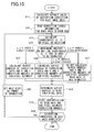
- the coordinate calculator 32 reads a distortion correction parameter for each image area from the ROM 34 and calculates a default value for calculation of coordinates for distortion correction according to the read parameter.
- step S12 the correction area determiner 31 reads from the ROM 34 the correction target information including a correction flag for each area ID (1 to n), coordinates (X, Y) of a base point and the width and height of the image area.
- step S13 the coordinate calculator 32 calculates the coordinates (X, Y) of a current image captured in accordance with the synchronous signal from the imaging unit 2, calculates coordinates (X, Y) of a target pixel according to the correction target information read from the ROM 34, and determines whether or not the coordinates (X, Y) are in an area to be distortion-corrected in step S14.
- Xn ⁇ X ⁇ Xn + Wn Yn ⁇ Y ⁇ Yn + Hn ENn correction flag for indicating validity of correction of area n
- Xn is an X coordinate of a base point of area n
- Yn is a Y coordinate of a base point of area n
- Wn is a width of area n
- Hn is a height of area n.
- the calculated X and Y correction amounts depend on the correction parameter for the area 2.
- step S18 the image line data buffer 30 reads the four source-pixel data designated by the buffer address on the basis of the results in steps S15 and S16.
- step S19 the pixel interpolator 33 interpolates the pixel in question on the basis of the data read in step S18 and the sub-pixel accurate X and Y correction amounts calculated in steps S15 and S16.
- step S20 Upon completion of the distortion correction by the pixel interpolation (YES in step S20) in each area, the series of distortion correction process is ended.
- the distortion correction process is not finished (NO in step S20)
- a next pixel is set to be a target of distortion correction in step S21 and subjected to the operations in steps S13 to S19.
- the two divided areas 1 and 2 of the image corresponding to the vehicle forward area 9 and raindrops detection area 8 can be subjected to the distortion correction with different correction amounts.
- the number of the areas 2 can be two or more such as the areas 2a, 2b in FIGs. 12 , 14 .
- the brightness signal of an optical component in a wavelength range other than the infrared wavelength range, which should be incident on the area 1 can be prevented from entering a part of the area 2 (raindrops detection area 8) in which brightness of an optical component in the infrared wavelength range is extracted through the top area 5a of the optical filter 5. This makes it possible to stably, accurately detect raindrops and prevent a decrease in the detection accuracy.
- the vehicle control system 20 is configured to detect the raindrops attached on the windshield 28 from the area 2 of an image by the imaging unit 2 of the imaging device 1. Alternatively, it can be configured to detect a fog on the inner surface of the windshield or a frost or smudge on the outer surface thereof.
- software or a program for causing a computer to execute the distortion correction by the distortion corrector 10 shown in either or both of FIG. 9 and FIG. 15 can be provided.
- Such software or program can be supplied to the imaging device 1 or vehicle control system 20 via a network or various kinds of storage medium.
- a CPU of a computer in the imaging device 1 or vehicle control system 20 can read and execute the program.
- an image in the first area is subjected to a first distortion correction while an image in the second area is not subjected to a distortion correction or subjected to a second distortion correction different from the first distortion correction to avoid the second area from being affected by the first distortion correction.
Landscapes
- Physics & Mathematics (AREA)
- General Physics & Mathematics (AREA)
- Engineering & Computer Science (AREA)
- Theoretical Computer Science (AREA)
- Image Processing (AREA)
- Closed-Circuit Television Systems (AREA)
- Studio Devices (AREA)
Abstract
Description
- The present invention relates to an image processing unit, an imaging device, and vehicle control system and program applicable to an in-vehicle camera which captures an image of the outside of a vehicle through a front glass element such as windshield.
- Japanese Patent No.
4326999 -
Reference 1 further describes setting two areas, i.e., attached matter detection area and vehicle forward area in a captured image. In the attached matter detection area, an optical filter is provided to transmit a light with an infrared wavelength range, for example, to detect attached matter such as raindrops on the windshield. At the same time, in the vehicle forward area an object such as a white line marking ahead of the vehicle is detected. - In
Reference 1 the camera includes a lens ahead of an image sensor so that a subject image incident through the lens, such as the raindrops or white line marking ahead of the vehicle, is formed on the image sensor. It is known that due to the optical property of a lens, a distortion occurs in a subject image formed on the image sensor. - It may be not be able to accurately identify an object ahead of the vehicle, for example, white line marking or a preceding vehicle from a captured image including a distortion. Japanese Patent Application Publication No.
2007-189361 - If the distortion correction in
Reference 2 is applied to the captured image inReference 1 having the attached matter detection area and vehicle forward area, the entire captured image including the attached matter detection area and vehicle forward area are evenly subjected to the distortion correction. Distortion needs to be accurately corrected in the vehicle forward area to improve the recognition of a target object while distortion does not need to be corrected in the attached matter detection area for detecting raindrops. - By the distortion correction in
Reference 2 to the entire image, a part of the vehicle forward area may be moved and enter the attached matter detection area. - That is, in attached matter detection area brightness signals of optical components in an infrared wavelength range are extracted through the optical filter, as described above. When brightness signals of optical components in the other wavelength range enter the attached matter detection area, an error may occur in the values of brightness signals output therefrom for raindrops detection, decreasing the accuracy of raindrops detection.
- The present invention aims to provide an image processing unit, an imaging device, and vehicle control system and program which can prevent a decrease in the accuracy with which raindrops are detected in an attached matter detection area due to distortion correction.
- In one embodiment an image processing unit comprises a distortion corrector to correct a distortion of an image of a subject formed on an image sensor via an imaging lens in accordance with an optical property of the imaging lens. The image sensor has a light-receiving surface including a first area and a second area in which images used for first and second purposes are captured, respectively. The distortion corrector is adapted to perform a first distortion correction on an image in the first area, and perform a second distortion correction different from the first distortion correction or perform no distortion correction on an image in the second area.
- Features, embodiments, and advantages of the present invention will become apparent from the following detailed description with reference to the accompanying drawings:
-
FIG. 1 schematically shows the structure of an imaging device incorporating an image processing unit according to one embodiment of the present invention; -
FIG. 2 is a schematic block diagram, showing a vehicle control system according to one embodiment incorporating the imaging device inFIG. 1 by way of example; -
FIG. 3 shows the entire image area formed on the image sensor via an imaging lens; -
FIG. 4 shows one example of an image formed on the image sensor via the imaging lens; -
FIG. 5 is a block diagram of the structure of a distortion corrector by way of example; -
FIG. 6 shows the light receiving surface of the image sensor and the entire image area captured by an imaging unit in association with each other; -
FIG. 7 shows one example of the positions of four source pixels and a destination pixel; -
FIG. 8 shows the positions of four source pixels and a destination pixel in detail; -
FIG. 9 is a flowchart of the process of distortion correction by a distortion corrector by way of example; -
FIG. 10 shows an example of an image having two vertically divided areas; -
FIG. 11 shows another example of an image having two vertically divided areas; -
FIG. 12 shows an example of an image having three horizontally divided areas; -
FIG. 13 shows an example of an image having a divided area at the bottom center; -
FIG. 14 shows an example of an image having three vertically divided areas; and -
FIG. 15 is a flowchart of the process of distortion correction by a distortion corrector by way of example. - Hereinafter, embodiments of the present invention will be described in detail with reference to the accompanying drawings. Wherever possible, the same reference numbers will be used throughout the drawings to refer to the same or like parts.
-
FIG. 1 schematically shows the structure of an imaging device incorporating an image processing unit according to one embodiment of the present invention.FIG. 2 is a schematic block diagram showing a vehicle control system incorporating the imaging device inFIG. 1 by way of example. - In
FIG. 1 animaging device 1 comprises animaging unit 2 and animage processing unit 3. - The
imaging unit 2 includes animaging lens 4, anoptical filter 5, and animage sensor 7 such as CCD mounted on asubstrate 6. Theoptical filter 5 includes anarea 5a at the top through which only infrared light in a certain infrared wavelength range is transmitted and anotherarea 5b at the bottom through which light in a visible wavelength range is transmitted. Light-receiving elements or pixels are two-dimensionally arranged on theimage sensor 7. Theimaging lens 4 is comprised of plural lenses although only one lens is shown inFIG. 1 . - The
optical filter 5 is disposed to face the front side of theimage sensor 7. The whole area of an image formed on theimage sensor 7 via theimaging lens 4 is divided into araindrops detection area 8 as a second area and a vehicleforward area 9 as a first area, for example. The raindrops detection area through which infrared light transmits corresponds to thetop area 5a while the vehicleforward area 9 through which visible light transmits corresponds to thebottom area 5b, as shown inFIG. 3 . - Note that the image formed on the
image sensor 7 via theimaging lens 4 is an inverted image so that thetop area 5a of theoptical filter 5 corresponds to theraindrops detection area 8 at the bottom as shown inFIG. 3 . - The
image sensor 7 converts the image into electric signals and outputs them to theimage processing unit 3. Theimage processing unit 3 performs known signal processing on the electric signals to generate displayable or storable image data. - The
image processing unit 3 further comprises adistortion corrector 10 to correct a distortion of generated image data by signal processing, which occurs due to the optical property of the lenses of theimaging lens 4. The structure of thedistortion corrector 10 and distortion correction will be described in detail later. - A
vehicle control system 20 according to the present embodiment inFIG. 2 comprises the above-describedimaging device 1, alight source 21, alight source controller 22, araindrops detector 23 as an attached matter detector, a vehicleforward detector 24, an in-vehicle controller (ECU) 25, awiper controller 26 and alamp controller 27. - According to the
vehicle control system 20 theimaging unit 2 of theimaging device 1 images an area ahead of the vehicle through awindshield 28 as a plate element with an optical permeability, and theimage processing unit 3 generates an image including theraindrops detection area 8 and vehicleforward area 9 inFIG. 3 . Thedistortion corrector 10 corrects a distortion of the generated image. - The
light source controller 22 controls thelight source 21 to project an infrared light beam to thewindshield 28 in synchronization with the imaging operation of theimaging device 1. Thetop area 5a of theoptical filter 5 functions to selectively transmit a light with an infrared wavelength range among the light beam from thelight source 21. Thereby, withraindrops 29 attached on the surface of thewindshield 28, the infrared light beam from thelight source 21 is reflected by the raindrops and the reflected light is imaged on theimage sensor 7 via theimaging lens 4 and thetop area 5a of theoptical filter 5. - Meanwhile, the
imaging unit 2 of theimaging device 1 images a vehicle forward area through thewindshield 28 and forms an image on theimage sensor 7 via theimaging lens 4 and thebottom area 5b of theoptical filter 5. -
FIG. 4 shows an example of an image including aroad surface 30 ahead of the vehicle in the vehicleforward area 9 and theraindrops 29 in theraindrops detection area 8 when captured by theimaging device 1 through thewindshield 28. Thus, the infrared light beam is irradiated from thelight source 21 to thewindshield 28, thereby to be able to properly project the image of theraindrops 29 in theraindrops detection area 8, with an influence from sunlight and streetlights reduced. - The
raindrops detector 23 receives image data in theraindrops detection area 8 from theimaging device 1 orimage processing unit 3. Raindrops can be detected in the following manner by way of example. - When the
windshield 28 is irradiated with the infrared light from thelight source 21 and imaged by theimaging device 1, with or without the raindrops attached thereon, the brightness of the entireraindrops detection area 8 differs. The larger the amount of raindrops attached on thewindshield 28, the higher the brightness value because of an increase in the amount of reflected light by the raindrops. In view of this, thresholds of brightness values are acquired by experiment and stored in a memory in advance. Theraindrops detector 23 is configured to detect an attached raindrop according to the brightness value of image data in the entireraindrops detection area 8. When the brightness value exceeds a threshold, it determines that raindrops are attached on the windshield. - Moreover, the vehicle forward
detector 24 performs predetermined image processing on the image data in the vehicle forwardarea 9 input from theimaging device 1 orimage processing unit 3 and detects a traffic lane (white line marking) or a preceding vehicle, for example. - Then, the in-
vehicle ECU 25 receives detected raindrops information from theraindrops detector 23 and outputs a signal to thewiper controller 26 in accordance with the raindrops information to operate a not-shown wiper to remove the raindrops from the surface of thewindshield 28. Alternatively, a washer liquid can be sprayed onto thewindshield 28 in replace of the wiper operation. - Further, the in-
vehicle ECU 25 receives vehicle forward information including taillights of a preceding vehicle at night from the vehicle forwarddetector 24 and outputs a signal to thelamp controller 27 in accordance with the information and controls the switching of the taillights between a high beam and a low beam. Alternatively, the in-vehicle ECU 25 can be configured to output a signal to a brake controller to operate the brake when recognizing approaching a preceding vehicle from the vehicle forward information, for example. - The structure of the
distortion corrector 10 is described with reference toFIG. 5 . The vehicle forwarddetector 24 is required to accurately recognize a white line marking or a preceding vehicle ahead of the vehicle so that a distortion of the vehicle forwardarea 9 of a captured image needs to be accurately corrected. - The
distortion corrector 10 inFIG. 5 comprises an imageline data buffer 30, acorrection area determiner 31, a coordinatecalculator 32, apixel interpolator 33 and aROM 34 as a storage medium. TheROM 34 contains correction target information including a distortion correction parameter for each image area in line with the property of theimaging lens 4, an area ID for each image area, coordinates (X, Y) in the entire effective image area (coordinates of a base point in the top left of each image area) for each area ID, and the width and height of each image area. - The image
line data buffer 30 receives image data and a synchronous signal from theimaging unit 2 and holds a necessary number of lines of pixel data for distortion correction in a ring buffer format. It outputs four neighboring pixel data to thepixel interpolator 33 according to a buffer address designated by the coordinatecalculator 32. The four neighboring pixels are the pixel designated by the buffer address and three neighboring pixels to the right, below, and obliquely right downward. - The
correction area determiner 31 calculates coordinates of a current image in accordance with a synchronous signal from theimaging unit 2 and compares them with the correction target information from theROM 34, to determine whether the pixel in question is a target pixel to be distortion-corrected. It then outputs an area ID, a correction valid signal indicating a target or not of distortion correction, and a synchronous signal to the coordinatecalculator 32. - The coordinate
calculator 32 then reads a distortion correction parameter from theROM 34 to calculate coordinates for distortion correction. It calculates pixel coordinates after distortion correction relative to a pixel position before distortion correction as an address of the line data buffer expressed in unit of a pixel (integer value) and a sub-pixel accurate brightness correction amount. Also, it outputs, for each pixel of each image area, an address of the imageline data buffer 30 to be a target of correction and a correction amount for calculating a brightness at sub-pixel accuracy, in accordance with the area ID, correction valid signal, and synchronous signal from thecorrection area determiner 31. That is, the coordinatecalculator 32 reads the distortion correction parameter from the storage medium and outputs an address, expressed in unit of a pixel, of the image line data buffer specified by the distortion correction parameter and an interpolation value for a distortion correction amount of less than the unit of a pixel based on the address. The interpolation value is an X correction amount in a horizontal direction of the image and a Y correction amount in a vertical direction of the image. - The coordinate
calculator 32 designates a pixel data address as a reference to a source pixel to be moved for distortion correction, to control a read of the imageline data buffer 30 and outputs an interpolation value to thepixel interpolator 33 as an X correction amount in image horizontal direction and a Y correction amount in image vertical direction. The interpolation value is an intermediate value among the four-pixel data and corresponds to a distortion correction amount of less than unit of a pixel. - The
pixel interpolator 33 receives the four-pixel data read from the imageline data buffer 30 and the interpolation value from the coordinatecalculator 32 to calculate a value of a destination pixel by bilinear interpolation. -
FIG. 6 shows the entire image area captured by theimaging unit 2, which corresponds to the light-receiving surface of theimage sensor 7 on which the pixels are arranged. A subject image including a distortion is formed on the light receiving surface. - In
FIG. 6 anarea 1 corresponds to the vehicle forwardarea 9 as a first area while anarea 2 corresponds to theraindrops detection area 8 as a second area. An area A surrounded by a broken line is the outermost area of the image in which a distortion occurs. The outermost area of an ideal image free from a distortion is located on the outermost pixels of the light receiving surface. The arrows in the drawing indicate a direction in which a brightness value is moved by distortion correction. InFIG. 6 distortion correction is performed only on thearea 1 corresponding to the vehicle forwardarea 9. -
FIG. 7 shows the positions of the four source pixels or target pixels to be distortion-corrected and a destination pixel in the top left area of the image area inFIG. 6 , for example. It shows that the brightness value calculated at sub-pixel accuracy is moved from the brightness values of the four source pixels. -
FIG. 8 shows the positions of the four source pixels as a target of correction and the destination pixel inFIG. 7 in detail and the pixel interpolation process of thepixel interpolator 33. - That is, in
FIG. 8 thepixel interpolator 33 reads the four source-pixel data from the imageline data buffer 30 and applies, by bilinear interpolation, the intermediate value thereof to a value of a destination pixel as a sub-pixel correction amount which is the X correction amount in image horizontal direction and the Y correction amount in image vertical direction. - The interpolation value for the bilinear interpolation of a destination pixel value is calculated in the following manner.
- Assumed that an address designated by the coordinate
calculator 32 falls at (0, 0) in the upper left of the four source-pixel data, a pixel value (a) (inFIG. 8 ) after distortion correction is expressed by the following equation:
where - A = ((T-ΔX) * a00 + ΔX * a10)/T
- B = ((T-ΔX) * a01 + ΔX * a11)/T
- At (0,0) pixel value = a00
- At (1,0) pixel value = a10
- At (0,1) pixel value = a01
- At (1,1) pixel value = a11
- X correction amount (after the decimal point) = ΔX
- Y correction amount (after the decimal point) = ΔY
- Resolution of a component less than a pixel = T
- When not performing distortion correction after a predetermined line in
FIG. 8 , the pixel address same as that before distortion correction is read and the X and Y correction amounts of zero are given by the coordinatecalculator 32. Thereby, a not-corrected source-pixel value is output. - Next, the distortion correction process of the
distortion corrector 10 is described in detail with reference toFIG. 9 by way of example. InFIG. 9 the image is divided into thearea 1 corresponding to the vehicle forwardarea 9 and thearea 2 corresponding to theraindrops detection area 8 as shown inFIG. 6 . Only thearea 1 or vehicleforward area 9 is subjected to the distortion correction. - In step S1 when the
distortion corrector 10 starts performing distortion correction, the coordinatecalculator 32 reads a distortion correction parameter for each image area from theROM 34 and calculates a default value for calculation of coordinates for distortion correction according to the read parameter. - In step S2 the
correction area determiner 31 reads from theROM 34 the correction target information including coordinates (X, Y) of a base point corresponding to thearea 1 or vehicleforward area 9 and the width and height of the image area. - In step S3 the
correction area determiner 31 calculates the coordinates of a current image according to the synchronous signal from theimaging unit 2 and compares them with the correction target information read from theROM 34 to determine whether or not the coordinates or pixel in question is the one to be distortion-corrected. If the coordinates are determined to be a target of distortion correction (YES in step S3), the coordinatecalculator 32 calculates a buffer address of correction data and X and Y correction amounts at sub-pixel accuracy in step S4. - With the coordinates determined as not a target of distortion correction (NO in step S3), the coordinate
calculator 32 does not calculate a buffer address and the sub-pixel accurate X and Y correction amounts in step S5 when the data in question is not to be corrected. - In step S6 the image
line data buffer 30 designates the buffer address to read the four source-pixel data. In step S7 thepixel interpolator 33 performs the above-described pixel interpolation on the basis of the data read in step S6 and the sub-pixel accurate X and Y correction amounts calculated in step S4. - Upon completion of the distortion correction by the pixel interpolation in the area 1(YES in step S8), a series of distortion correction process is ended. When the distortion correction process is not finished (NO in step S8), a next pixel is set to be a target of distortion correction in step S9 and subjected to the operation in steps S3 to S7.
- Thus, regarding the image having the two divided
areas area 9 andraindrops detection area 8, an object in thearea 1 or vehicleforward area 9 needs to be precisely recognized. According to the present embodiment, only thearea 1 is subjected to the distortion correction so that it is possible to prevent a part of thearea 1 from entering thearea 2. - That is, the brightness signal of an optical component in a wavelength range other than the infrared wavelength range, which should be incident on the
area 1, can be prevented from entering a part of the area 2 (raindrops detection area 8) in which the brightness signal of an optical component in the infrared wavelength range is extracted through thetop area 5a of theoptical filter 5. This makes it possible to stably, accurately detect raindrops and prevent a decrease in the detection accuracy. - In the distortion correction in
FIG. 9 thearea 2 is not subjected to the distortion correction as shown inFIG. 6 . Alternatively, it can be configured that distortion correction is performed on plural divided areas with respective different correction amounts. - Referring to
FIG. 10 , for example, a captured image include two vertically dividedareas area 9 andraindrops detection area 8, and these dividedareas FIG. 11 shows an example of a captured image having theareas area 2 corresponding to theraindrops detection area 8 is placed at top of the image and thearea 1 corresponding to the vehicle forwardarea 9 is placed at bottom. Theareas - Further,
FIG. 12 shows another example of a captured image having three horizontally divided areas, anarea 1 at the center corresponding to the vehicle forwardarea 9 and right and leftareas raindrops detection area 8. Theareas second areas -
FIG. 13 shows another example of a captured image having anarea 1 corresponding to the vehicle forwardarea 9 and anarea 2 corresponding to theraindrops detection area 8 at bottom center. Theareas - Further,
FIG. 14 shows another example of a captured image having three vertically divided areas, anarea 1 at the center corresponding to the vehicle forwardarea 9 and top andbottom areas raindrops detection area 8. Theareas second areas - In
FIG. 10 to FIG. 14 the areas of the light receiving surface surrounded by the broken line are the outermost areas of images in which a distortion occurs. The outermost area of an ideal image free from a distortion is located on the outermost pixels of the light receiving surface. The arrows in the drawings indicate a direction in which a brightness value is moved by distortion correction. - Next, referring to
FIG. 15 , the distortion correction to the divided image areas with different correction amounts is described in detail. - First, in step S11 when the
distortion corrector 10 starts performing distortion correction, the coordinatecalculator 32 reads a distortion correction parameter for each image area from theROM 34 and calculates a default value for calculation of coordinates for distortion correction according to the read parameter. - In step S12 the
correction area determiner 31 reads from theROM 34 the correction target information including a correction flag for each area ID (1 to n), coordinates (X, Y) of a base point and the width and height of the image area. - In step S13 the coordinate
calculator 32 calculates the coordinates (X, Y) of a current image captured in accordance with the synchronous signal from theimaging unit 2, calculates coordinates (X, Y) of a target pixel according to the correction target information read from theROM 34, and determines whether or not the coordinates (X, Y) are in an area to be distortion-corrected in step S14. - For the determining in step S14 the following three relations are used.


ENn: correction flag for indicating validity of correction of area n where Xn is an X coordinate of a base point of area n, Yn is a Y coordinate of a base point of area n, Wn is a width of area n, and Hn is a height of area n. - When determining that the coordinates (X, Y) are in the area 1 (in
FIG. 10 , for example) and EN1 = 1 (correction is valid) in step S14 by the three relations, the coordinatecalculator 32 proceeds to step S15 and calculates a buffer address of correction data and X and Y correction amounts at sub-pixel accuracy. The calculated X and Y correction amounts depend on a correction parameter for thearea 1. - Further, when determining that the coordinates (X, Y) are in the area 2 (in
FIG. 10 , for example) by the three relations and EN2 = 1 (correction is valid) in step S14, the coordinatecalculator 32 proceeds to step S16 and calculates a buffer address of data to be corrected and sub-pixel accurate X and Y correction amounts. The calculated X and Y correction amounts depend on the correction parameter for thearea 2. - When determining that the coordinates (X, Y) are in an area n as a non-target of distortion correction and ENn = 0 (correction is invalid) by the three relations in step S14, the coordinate
calculator 32 proceeds to step S17 and does not calculate a buffer address and sub-pixel accurate X and Y correction amounts when the data in question is not to be corrected. - In step S18 the image
line data buffer 30 reads the four source-pixel data designated by the buffer address on the basis of the results in steps S15 and S16. In step S19 thepixel interpolator 33 interpolates the pixel in question on the basis of the data read in step S18 and the sub-pixel accurate X and Y correction amounts calculated in steps S15 and S16. - Upon completion of the distortion correction by the pixel interpolation (YES in step S20) in each area, the series of distortion correction process is ended. When the distortion correction process is not finished (NO in step S20), a next pixel is set to be a target of distortion correction in step S21 and subjected to the operations in steps S13 to S19.
- Thus, having the
areas areas area 9 andraindrops detection area 8 can be subjected to the distortion correction with different correction amounts. Also, the number of theareas 2 can be two or more such as theareas FIGs. 12 ,14 . - As described above, the brightness signal of an optical component in a wavelength range other than the infrared wavelength range, which should be incident on the area 1 (vehicle forward area 9), can be prevented from entering a part of the area 2 (raindrops detection area 8) in which brightness of an optical component in the infrared wavelength range is extracted through the
top area 5a of theoptical filter 5. This makes it possible to stably, accurately detect raindrops and prevent a decrease in the detection accuracy. - According to the present embodiment the
vehicle control system 20 is configured to detect the raindrops attached on thewindshield 28 from thearea 2 of an image by theimaging unit 2 of theimaging device 1. Alternatively, it can be configured to detect a fog on the inner surface of the windshield or a frost or smudge on the outer surface thereof. - Further, according to the present embodiment software or a program for causing a computer to execute the distortion correction by the
distortion corrector 10 shown in either or both ofFIG. 9 andFIG. 15 can be provided. Such software or program can be supplied to theimaging device 1 orvehicle control system 20 via a network or various kinds of storage medium. A CPU of a computer in theimaging device 1 orvehicle control system 20 can read and execute the program. - As described above, according to the present invention an image in the first area is subjected to a first distortion correction while an image in the second area is not subjected to a distortion correction or subjected to a second distortion correction different from the first distortion correction to avoid the second area from being affected by the first distortion correction. This makes it possible to avoid a decrease in the accuracy at which attached matter including raindrops is detected due to the optical property of an imaging lens.
- Although the present invention has been described in terms of exemplary embodiments, it is not limited thereto. It should be appreciated that variations or modifications may be made in the embodiments described by persons skilled in the art without departing from the scope of the present invention as defined by the following claims.
Claims (7)
- An image processing unit (3) comprising a distortion corrector (10) to correct a distortion of an image of a subject formed on an image sensor (7) via an imaging lens (4) in accordance with an optical property of the imaging lens, the image sensor having a light-receiving surface including a first area (9) and a second area (8) in which images used for first and second purposes are captured, respectively, wherein
the distortion corrector (10) is adapted to perform a first distortion correction on an image in the first area, and perform a second distortion correction different from the first distortion correction or perform no distortion correction on an image in the second area. - An imaging device (1) comprising:an imaging unit (2) disposed inside a plate element (28) having a light permeability and including an image sensor (7) on which light-receiving elements are two-dimensionally arranged and an imaging lens (4) to capture an image of a subject on the image sensor through the plate element;a distortion corrector (10) to correct a distortion of an image captured by the imaging unit in accordance with an optical property of the imaging lens, whereinthe image sensor has a light-receiving surface including a first area (9) in which an image of a forward area outside the plate element is captured via the imaging lens and a second area (8) in which an image of attached matter on the plate element is captured via the imaging lens; andthe distortion corrector is adapted to perform a first distortion correction on the image in the first area, and perform a second distortion correction different from the first distortion correction or perform no distortion correction on an image in the second area.
- The imaging device (1) according to claim 2, further comprising:a light source (21) to project a light in a certain wavelength range to the plate element from an imaging unit's side; andan optical filter (5) provided between the imaging lens and the image sensor and including a partial area through which only the light in the certain wavelength range is transmitted, whereinthe second area is an area on which the light from the light source is reflected by the plate element and incident through the partial area of the optical filter.
- The imaging device (1) according to either claim 2 or claim 3, wherein
the distortion corrector (10) comprises:a storage medium (34) in which correction target information is stored, the correction target information including a distortion correction parameter for each image area in accordance with the imaging lens, an area ID for identifying an image area, X and Y coordinates in an entire effective image area, and a width and a height of each image area;an image line data buffer (30) to receive image data and a synchronous signal from the imaging unit and hold a necessary number of lines of pixel data for distortion correction in a ring buffer format;a correction area determiner (31) to calculate coordinates of a current image according to the synchronous signal from the imaging unit, compare the coordinates with the correction target information to determine whether the coordinates are a pixel to be distortion-corrected, and output the area ID, a correction valid signal, and the synchronous signal, the correction valid signal indicating a target or non-target of distortion correction;a coordinate calculator (32) to read the distortion correction parameter from the storage medium and output an address, expressed in unit of a pixel, of the image line data buffer specified by the distortion correction parameter and an interpolation value for a distortion correction amount of less than the unit of a pixel based on the address, the interpolation value being an X correction amount in a horizontal direction of the image and a Y correction amount in a vertical direction of the image; anda pixel interpolator (33) to receive data on four source pixels read from the image line data buffer (30) on the basis of the address specified by the coordinate calculator (32) and the interpolation value output from the coordinate calculator to calculate a value of a destination pixel by bilinear interpolation. - The imaging device (1) according to any one of claims 2 to 4, wherein
the second area includes a single area or a plurality of divided areas. - A vehicle control system (20) comprising:the imaging device (1) according to any one of claims 2 to 5, disposed inside a glass element (28) to capture an image through the glass element;a forward area detector (24) to recognize an object in a forward area of a vehicle from the image in the first area of the light-receiving surface of the image sensor;an attached matter detector (23) to detect attached matter on the glass element from the image in the second area of the light-receiving surface of the image sensor; anda controller (25) to control a predetermined operation of the vehicle on the basis of forward area information obtained by the forward area detector and control a wiper operation or an ejection of washer liquid on the basis of attached matter information obtained by the attached matter detector when the attached matter is detected.
- A non-transitory computer-readable storage medium storing a program for causing a computer to execute the processings of the image line data buffer, correction area determiner, coordinate calculator, and pixel interpolator according to claim 4.
Applications Claiming Priority (1)
| Application Number | Priority Date | Filing Date | Title |
|---|---|---|---|
| JP2013034556A JP6089767B2 (en) | 2013-02-25 | 2013-02-25 | Image processing apparatus, imaging apparatus, moving body control system, and program |
Publications (3)
| Publication Number | Publication Date |
|---|---|
| EP2770478A2 true EP2770478A2 (en) | 2014-08-27 |
| EP2770478A3 EP2770478A3 (en) | 2015-04-29 |
| EP2770478B1 EP2770478B1 (en) | 2019-10-02 |
Family
ID=50241083
Family Applications (1)
| Application Number | Title | Priority Date | Filing Date |
|---|---|---|---|
| EP14156277.7A Active EP2770478B1 (en) | 2013-02-25 | 2014-02-24 | Image processing unit, imaging device, and vehicle control system and program |
Country Status (2)
| Country | Link |
|---|---|
| EP (1) | EP2770478B1 (en) |
| JP (1) | JP6089767B2 (en) |
Cited By (4)
| Publication number | Priority date | Publication date | Assignee | Title |
|---|---|---|---|---|
| CN109429007A (en) * | 2017-08-28 | 2019-03-05 | 丰田自动车株式会社 | Image processing apparatus and filming apparatus |
| EP3557858A4 (en) * | 2016-12-15 | 2020-01-01 | Panasonic Intellectual Property Management Co., Ltd. | IMAGING DEVICE, AND IMAGING METHOD |
| CN112446338A (en) * | 2019-12-06 | 2021-03-05 | 黑芝麻智能科技(上海)有限公司 | Partial frame sensing method |
| WO2025086253A1 (en) * | 2023-10-27 | 2025-05-01 | 京东方科技集团股份有限公司 | Image correction method and system, and display device |
Families Citing this family (5)
| Publication number | Priority date | Publication date | Assignee | Title |
|---|---|---|---|---|
| WO2014007294A1 (en) * | 2012-07-03 | 2014-01-09 | クラリオン株式会社 | On-board device |
| KR101662432B1 (en) * | 2015-03-09 | 2016-10-04 | 주식회사 에스에이치에이치(Shh) | Brightness LED Headlights Automatic Control System for Railway Transport |
| JP6462536B2 (en) * | 2015-08-31 | 2019-01-30 | 日立オートモティブシステムズ株式会社 | Image processing device |
| JP2019004254A (en) * | 2017-06-13 | 2019-01-10 | 株式会社デンソー | Vehicle photographing device |
| JP7324683B2 (en) * | 2019-10-17 | 2023-08-10 | 株式会社Subaru | Image processing device |
Citations (2)
| Publication number | Priority date | Publication date | Assignee | Title |
|---|---|---|---|---|
| JP2007189361A (en) | 2006-01-12 | 2007-07-26 | Fujitsu General Ltd | Image sensor and camera using the same |
| JP4326999B2 (en) | 2003-08-12 | 2009-09-09 | 株式会社日立製作所 | Image processing system |
Family Cites Families (6)
| Publication number | Priority date | Publication date | Assignee | Title |
|---|---|---|---|---|
| US6681163B2 (en) * | 2001-10-04 | 2004-01-20 | Gentex Corporation | Moisture sensor and windshield fog detector |
| JP2005311868A (en) * | 2004-04-23 | 2005-11-04 | Auto Network Gijutsu Kenkyusho:Kk | Vehicle periphery visual recognition device |
| US7881496B2 (en) * | 2004-09-30 | 2011-02-01 | Donnelly Corporation | Vision system for vehicle |
| JP4104631B2 (en) * | 2006-03-27 | 2008-06-18 | 三洋電機株式会社 | Driving support device |
| JP4668838B2 (en) * | 2006-05-16 | 2011-04-13 | 株式会社日本自動車部品総合研究所 | Raindrop detection device and wiper control device |
| JP5448056B2 (en) * | 2009-09-03 | 2014-03-19 | スズキ株式会社 | Distorted image correction apparatus and method |
-
2013
- 2013-02-25 JP JP2013034556A patent/JP6089767B2/en not_active Expired - Fee Related
-
2014
- 2014-02-24 EP EP14156277.7A patent/EP2770478B1/en active Active
Patent Citations (2)
| Publication number | Priority date | Publication date | Assignee | Title |
|---|---|---|---|---|
| JP4326999B2 (en) | 2003-08-12 | 2009-09-09 | 株式会社日立製作所 | Image processing system |
| JP2007189361A (en) | 2006-01-12 | 2007-07-26 | Fujitsu General Ltd | Image sensor and camera using the same |
Cited By (5)
| Publication number | Priority date | Publication date | Assignee | Title |
|---|---|---|---|---|
| EP3557858A4 (en) * | 2016-12-15 | 2020-01-01 | Panasonic Intellectual Property Management Co., Ltd. | IMAGING DEVICE, AND IMAGING METHOD |
| CN109429007A (en) * | 2017-08-28 | 2019-03-05 | 丰田自动车株式会社 | Image processing apparatus and filming apparatus |
| CN109429007B (en) * | 2017-08-28 | 2020-12-18 | 丰田自动车株式会社 | Image processing device and photographing device |
| CN112446338A (en) * | 2019-12-06 | 2021-03-05 | 黑芝麻智能科技(上海)有限公司 | Partial frame sensing method |
| WO2025086253A1 (en) * | 2023-10-27 | 2025-05-01 | 京东方科技集团股份有限公司 | Image correction method and system, and display device |
Also Published As
| Publication number | Publication date |
|---|---|
| EP2770478A3 (en) | 2015-04-29 |
| JP6089767B2 (en) | 2017-03-08 |
| EP2770478B1 (en) | 2019-10-02 |
| JP2014165638A (en) | 2014-09-08 |
Similar Documents
| Publication | Publication Date | Title |
|---|---|---|
| EP2770478B1 (en) | Image processing unit, imaging device, and vehicle control system and program | |
| US11205284B2 (en) | Vehicle-mounted camera pose estimation method, apparatus, and system, and electronic device | |
| US7957559B2 (en) | Apparatus and system for recognizing environment surrounding vehicle | |
| CN104657735B (en) | Method for detecting lane lines, system, lane departure warning method and system | |
| US8077204B2 (en) | Vehicle periphery monitoring device, vehicle, vehicle periphery monitoring program, and vehicle periphery monitoring method | |
| JP4433045B2 (en) | Exposure control device and exposure control program | |
| JP4389999B2 (en) | Exposure control device and exposure control program | |
| JP5950196B2 (en) | Imaging apparatus, and image analysis apparatus and moving apparatus using the same | |
| CN110023951B (en) | Information processing apparatus, imaging apparatus, device control system, information processing method, and computer-readable recording medium | |
| US20130141520A1 (en) | Lane tracking system | |
| US8526681B2 (en) | On-vehicle image processing device for vehicular control | |
| US20140085473A1 (en) | In-vehicle camera apparatus | |
| US10148938B2 (en) | Vehicle-mounted image recognition device to set a stereoscopic-vision and monocular-vision image areas | |
| US20200074212A1 (en) | Information processing device, imaging device, equipment control system, mobile object, information processing method, and computer-readable recording medium | |
| US8983147B2 (en) | Eyelid detection device | |
| JP2013137767A (en) | Obstacle detection method and driver support system | |
| US20120128211A1 (en) | Distance calculation device for vehicle | |
| JP6032141B2 (en) | Travel road marking detection device and travel road marking detection method | |
| US9827906B2 (en) | Image processing apparatus | |
| JP5129094B2 (en) | Vehicle periphery monitoring device | |
| JP2014067320A (en) | Stereo camera device | |
| KR101982091B1 (en) | Surround view monitoring system | |
| JP2015099556A (en) | Positioning device and headlight control system | |
| JP5867207B2 (en) | Image processing apparatus, image processing system, and image processing method | |
| JP4956841B2 (en) | VEHICLE IMAGE PROCESSING DEVICE, VEHICLE, AND VEHICLE IMAGE PROCESSING PROGRAM |
Legal Events
| Date | Code | Title | Description |
|---|---|---|---|
| PUAI | Public reference made under article 153(3) epc to a published international application that has entered the european phase |
Free format text: ORIGINAL CODE: 0009012 |
|
| 17P | Request for examination filed |
Effective date: 20140224 |
|
| AK | Designated contracting states |
Kind code of ref document: A2 Designated state(s): AL AT BE BG CH CY CZ DE DK EE ES FI FR GB GR HR HU IE IS IT LI LT LU LV MC MK MT NL NO PL PT RO RS SE SI SK SM TR |
|
| AX | Request for extension of the european patent |
Extension state: BA ME |
|
| PUAL | Search report despatched |
Free format text: ORIGINAL CODE: 0009013 |
|
| AK | Designated contracting states |
Kind code of ref document: A3 Designated state(s): AL AT BE BG CH CY CZ DE DK EE ES FI FR GB GR HR HU IE IS IT LI LT LU LV MC MK MT NL NO PL PT RO RS SE SI SK SM TR |
|
| AX | Request for extension of the european patent |
Extension state: BA ME |
|
| RIC1 | Information provided on ipc code assigned before grant |
Ipc: G06T 5/00 20060101AFI20150323BHEP Ipc: G06T 3/00 20060101ALI20150323BHEP |
|
| STAA | Information on the status of an ep patent application or granted ep patent |
Free format text: STATUS: EXAMINATION IS IN PROGRESS |
|
| 17Q | First examination report despatched |
Effective date: 20180813 |
|
| GRAP | Despatch of communication of intention to grant a patent |
Free format text: ORIGINAL CODE: EPIDOSNIGR1 |
|
| STAA | Information on the status of an ep patent application or granted ep patent |
Free format text: STATUS: GRANT OF PATENT IS INTENDED |
|
| INTG | Intention to grant announced |
Effective date: 20190520 |
|
| GRAS | Grant fee paid |
Free format text: ORIGINAL CODE: EPIDOSNIGR3 |
|
| GRAA | (expected) grant |
Free format text: ORIGINAL CODE: 0009210 |
|
| STAA | Information on the status of an ep patent application or granted ep patent |
Free format text: STATUS: THE PATENT HAS BEEN GRANTED |
|
| AK | Designated contracting states |
Kind code of ref document: B1 Designated state(s): AL AT BE BG CH CY CZ DE DK EE ES FI FR GB GR HR HU IE IS IT LI LT LU LV MC MK MT NL NO PL PT RO RS SE SI SK SM TR |
|
| REG | Reference to a national code |
Ref country code: GB Ref legal event code: FG4D |
|
| REG | Reference to a national code |
Ref country code: CH Ref legal event code: EP Ref country code: AT Ref legal event code: REF Ref document number: 1187011 Country of ref document: AT Kind code of ref document: T Effective date: 20191015 |
|
| REG | Reference to a national code |
Ref country code: DE Ref legal event code: R096 Ref document number: 602014054449 Country of ref document: DE |
|
| REG | Reference to a national code |
Ref country code: IE Ref legal event code: FG4D |
|
| REG | Reference to a national code |
Ref country code: NL Ref legal event code: MP Effective date: 20191002 |
|
| REG | Reference to a national code |
Ref country code: LT Ref legal event code: MG4D |
|
| REG | Reference to a national code |
Ref country code: AT Ref legal event code: MK05 Ref document number: 1187011 Country of ref document: AT Kind code of ref document: T Effective date: 20191002 |
|
| PG25 | Lapsed in a contracting state [announced via postgrant information from national office to epo] |
Ref country code: ES Free format text: LAPSE BECAUSE OF FAILURE TO SUBMIT A TRANSLATION OF THE DESCRIPTION OR TO PAY THE FEE WITHIN THE PRESCRIBED TIME-LIMIT Effective date: 20191002 Ref country code: AT Free format text: LAPSE BECAUSE OF FAILURE TO SUBMIT A TRANSLATION OF THE DESCRIPTION OR TO PAY THE FEE WITHIN THE PRESCRIBED TIME-LIMIT Effective date: 20191002 Ref country code: NL Free format text: LAPSE BECAUSE OF FAILURE TO SUBMIT A TRANSLATION OF THE DESCRIPTION OR TO PAY THE FEE WITHIN THE PRESCRIBED TIME-LIMIT Effective date: 20191002 Ref country code: BG Free format text: LAPSE BECAUSE OF FAILURE TO SUBMIT A TRANSLATION OF THE DESCRIPTION OR TO PAY THE FEE WITHIN THE PRESCRIBED TIME-LIMIT Effective date: 20200102 Ref country code: FI Free format text: LAPSE BECAUSE OF FAILURE TO SUBMIT A TRANSLATION OF THE DESCRIPTION OR TO PAY THE FEE WITHIN THE PRESCRIBED TIME-LIMIT Effective date: 20191002 Ref country code: GR Free format text: LAPSE BECAUSE OF FAILURE TO SUBMIT A TRANSLATION OF THE DESCRIPTION OR TO PAY THE FEE WITHIN THE PRESCRIBED TIME-LIMIT Effective date: 20200103 Ref country code: PT Free format text: LAPSE BECAUSE OF FAILURE TO SUBMIT A TRANSLATION OF THE DESCRIPTION OR TO PAY THE FEE WITHIN THE PRESCRIBED TIME-LIMIT Effective date: 20200203 Ref country code: LT Free format text: LAPSE BECAUSE OF FAILURE TO SUBMIT A TRANSLATION OF THE DESCRIPTION OR TO PAY THE FEE WITHIN THE PRESCRIBED TIME-LIMIT Effective date: 20191002 Ref country code: PL Free format text: LAPSE BECAUSE OF FAILURE TO SUBMIT A TRANSLATION OF THE DESCRIPTION OR TO PAY THE FEE WITHIN THE PRESCRIBED TIME-LIMIT Effective date: 20191002 Ref country code: SE Free format text: LAPSE BECAUSE OF FAILURE TO SUBMIT A TRANSLATION OF THE DESCRIPTION OR TO PAY THE FEE WITHIN THE PRESCRIBED TIME-LIMIT Effective date: 20191002 Ref country code: LV Free format text: LAPSE BECAUSE OF FAILURE TO SUBMIT A TRANSLATION OF THE DESCRIPTION OR TO PAY THE FEE WITHIN THE PRESCRIBED TIME-LIMIT Effective date: 20191002 Ref country code: NO Free format text: LAPSE BECAUSE OF FAILURE TO SUBMIT A TRANSLATION OF THE DESCRIPTION OR TO PAY THE FEE WITHIN THE PRESCRIBED TIME-LIMIT Effective date: 20200102 |
|
| PGFP | Annual fee paid to national office [announced via postgrant information from national office to epo] |
Ref country code: GB Payment date: 20200219 Year of fee payment: 7 Ref country code: DE Payment date: 20200219 Year of fee payment: 7 |
|
| PG25 | Lapsed in a contracting state [announced via postgrant information from national office to epo] |
Ref country code: RS Free format text: LAPSE BECAUSE OF FAILURE TO SUBMIT A TRANSLATION OF THE DESCRIPTION OR TO PAY THE FEE WITHIN THE PRESCRIBED TIME-LIMIT Effective date: 20191002 Ref country code: HR Free format text: LAPSE BECAUSE OF FAILURE TO SUBMIT A TRANSLATION OF THE DESCRIPTION OR TO PAY THE FEE WITHIN THE PRESCRIBED TIME-LIMIT Effective date: 20191002 Ref country code: IS Free format text: LAPSE BECAUSE OF FAILURE TO SUBMIT A TRANSLATION OF THE DESCRIPTION OR TO PAY THE FEE WITHIN THE PRESCRIBED TIME-LIMIT Effective date: 20200224 Ref country code: CZ Free format text: LAPSE BECAUSE OF FAILURE TO SUBMIT A TRANSLATION OF THE DESCRIPTION OR TO PAY THE FEE WITHIN THE PRESCRIBED TIME-LIMIT Effective date: 20191002 |
|
| PG25 | Lapsed in a contracting state [announced via postgrant information from national office to epo] |
Ref country code: AL Free format text: LAPSE BECAUSE OF FAILURE TO SUBMIT A TRANSLATION OF THE DESCRIPTION OR TO PAY THE FEE WITHIN THE PRESCRIBED TIME-LIMIT Effective date: 20191002 |
|
| PGFP | Annual fee paid to national office [announced via postgrant information from national office to epo] |
Ref country code: FR Payment date: 20200219 Year of fee payment: 7 |
|
| REG | Reference to a national code |
Ref country code: DE Ref legal event code: R097 Ref document number: 602014054449 Country of ref document: DE |
|
| PG2D | Information on lapse in contracting state deleted |
Ref country code: IS |
|
| PG25 | Lapsed in a contracting state [announced via postgrant information from national office to epo] |
Ref country code: RO Free format text: LAPSE BECAUSE OF FAILURE TO SUBMIT A TRANSLATION OF THE DESCRIPTION OR TO PAY THE FEE WITHIN THE PRESCRIBED TIME-LIMIT Effective date: 20191002 Ref country code: EE Free format text: LAPSE BECAUSE OF FAILURE TO SUBMIT A TRANSLATION OF THE DESCRIPTION OR TO PAY THE FEE WITHIN THE PRESCRIBED TIME-LIMIT Effective date: 20191002 Ref country code: DK Free format text: LAPSE BECAUSE OF FAILURE TO SUBMIT A TRANSLATION OF THE DESCRIPTION OR TO PAY THE FEE WITHIN THE PRESCRIBED TIME-LIMIT Effective date: 20191002 Ref country code: IS Free format text: LAPSE BECAUSE OF FAILURE TO SUBMIT A TRANSLATION OF THE DESCRIPTION OR TO PAY THE FEE WITHIN THE PRESCRIBED TIME-LIMIT Effective date: 20200202 |
|
| PLBE | No opposition filed within time limit |
Free format text: ORIGINAL CODE: 0009261 |
|
| STAA | Information on the status of an ep patent application or granted ep patent |
Free format text: STATUS: NO OPPOSITION FILED WITHIN TIME LIMIT |
|
| PG25 | Lapsed in a contracting state [announced via postgrant information from national office to epo] |
Ref country code: SK Free format text: LAPSE BECAUSE OF FAILURE TO SUBMIT A TRANSLATION OF THE DESCRIPTION OR TO PAY THE FEE WITHIN THE PRESCRIBED TIME-LIMIT Effective date: 20191002 Ref country code: IT Free format text: LAPSE BECAUSE OF FAILURE TO SUBMIT A TRANSLATION OF THE DESCRIPTION OR TO PAY THE FEE WITHIN THE PRESCRIBED TIME-LIMIT Effective date: 20191002 Ref country code: SM Free format text: LAPSE BECAUSE OF FAILURE TO SUBMIT A TRANSLATION OF THE DESCRIPTION OR TO PAY THE FEE WITHIN THE PRESCRIBED TIME-LIMIT Effective date: 20191002 |
|
| 26N | No opposition filed |
Effective date: 20200703 |
|
| REG | Reference to a national code |
Ref country code: CH Ref legal event code: PL |
|
| REG | Reference to a national code |
Ref country code: BE Ref legal event code: MM Effective date: 20200229 |
|
| PG25 | Lapsed in a contracting state [announced via postgrant information from national office to epo] |
Ref country code: MC Free format text: LAPSE BECAUSE OF FAILURE TO SUBMIT A TRANSLATION OF THE DESCRIPTION OR TO PAY THE FEE WITHIN THE PRESCRIBED TIME-LIMIT Effective date: 20191002 Ref country code: LU Free format text: LAPSE BECAUSE OF NON-PAYMENT OF DUE FEES Effective date: 20200224 |
|
| PG25 | Lapsed in a contracting state [announced via postgrant information from national office to epo] |
Ref country code: SI Free format text: LAPSE BECAUSE OF FAILURE TO SUBMIT A TRANSLATION OF THE DESCRIPTION OR TO PAY THE FEE WITHIN THE PRESCRIBED TIME-LIMIT Effective date: 20191002 Ref country code: CH Free format text: LAPSE BECAUSE OF NON-PAYMENT OF DUE FEES Effective date: 20200229 Ref country code: LI Free format text: LAPSE BECAUSE OF NON-PAYMENT OF DUE FEES Effective date: 20200229 |
|
| PG25 | Lapsed in a contracting state [announced via postgrant information from national office to epo] |
Ref country code: IE Free format text: LAPSE BECAUSE OF NON-PAYMENT OF DUE FEES Effective date: 20200224 |
|
| PG25 | Lapsed in a contracting state [announced via postgrant information from national office to epo] |
Ref country code: BE Free format text: LAPSE BECAUSE OF NON-PAYMENT OF DUE FEES Effective date: 20200229 |
|
| REG | Reference to a national code |
Ref country code: DE Ref legal event code: R119 Ref document number: 602014054449 Country of ref document: DE |
|
| GBPC | Gb: european patent ceased through non-payment of renewal fee |
Effective date: 20210224 |
|
| PG25 | Lapsed in a contracting state [announced via postgrant information from national office to epo] |
Ref country code: GB Free format text: LAPSE BECAUSE OF NON-PAYMENT OF DUE FEES Effective date: 20210224 Ref country code: FR Free format text: LAPSE BECAUSE OF NON-PAYMENT OF DUE FEES Effective date: 20210228 Ref country code: DE Free format text: LAPSE BECAUSE OF NON-PAYMENT OF DUE FEES Effective date: 20210901 |
|
| PG25 | Lapsed in a contracting state [announced via postgrant information from national office to epo] |
Ref country code: TR Free format text: LAPSE BECAUSE OF FAILURE TO SUBMIT A TRANSLATION OF THE DESCRIPTION OR TO PAY THE FEE WITHIN THE PRESCRIBED TIME-LIMIT Effective date: 20191002 Ref country code: MT Free format text: LAPSE BECAUSE OF FAILURE TO SUBMIT A TRANSLATION OF THE DESCRIPTION OR TO PAY THE FEE WITHIN THE PRESCRIBED TIME-LIMIT Effective date: 20191002 Ref country code: CY Free format text: LAPSE BECAUSE OF FAILURE TO SUBMIT A TRANSLATION OF THE DESCRIPTION OR TO PAY THE FEE WITHIN THE PRESCRIBED TIME-LIMIT Effective date: 20191002 |
|
| PG25 | Lapsed in a contracting state [announced via postgrant information from national office to epo] |
Ref country code: MK Free format text: LAPSE BECAUSE OF FAILURE TO SUBMIT A TRANSLATION OF THE DESCRIPTION OR TO PAY THE FEE WITHIN THE PRESCRIBED TIME-LIMIT Effective date: 20191002 |