EP2770412A1 - Projector - Google Patents
Projector Download PDFInfo
- Publication number
- EP2770412A1 EP2770412A1 EP14154092.2A EP14154092A EP2770412A1 EP 2770412 A1 EP2770412 A1 EP 2770412A1 EP 14154092 A EP14154092 A EP 14154092A EP 2770412 A1 EP2770412 A1 EP 2770412A1
- Authority
- EP
- European Patent Office
- Prior art keywords
- detection object
- touch pen
- laser beam
- received
- change
- Prior art date
- Legal status (The legal status is an assumption and is not a legal conclusion. Google has not performed a legal analysis and makes no representation as to the accuracy of the status listed.)
- Withdrawn
Links
Images





Classifications
-
- G—PHYSICS
- G03—PHOTOGRAPHY; CINEMATOGRAPHY; ANALOGOUS TECHNIQUES USING WAVES OTHER THAN OPTICAL WAVES; ELECTROGRAPHY; HOLOGRAPHY
- G03B—APPARATUS OR ARRANGEMENTS FOR TAKING PHOTOGRAPHS OR FOR PROJECTING OR VIEWING THEM; APPARATUS OR ARRANGEMENTS EMPLOYING ANALOGOUS TECHNIQUES USING WAVES OTHER THAN OPTICAL WAVES; ACCESSORIES THEREFOR
- G03B21/00—Projectors or projection-type viewers; Accessories therefor
- G03B21/14—Details
- G03B21/142—Adjusting of projection optics
-
- G—PHYSICS
- G06—COMPUTING OR CALCULATING; COUNTING
- G06F—ELECTRIC DIGITAL DATA PROCESSING
- G06F3/00—Input arrangements for transferring data to be processed into a form capable of being handled by the computer; Output arrangements for transferring data from processing unit to output unit, e.g. interface arrangements
- G06F3/01—Input arrangements or combined input and output arrangements for interaction between user and computer
- G06F3/03—Arrangements for converting the position or the displacement of a member into a coded form
- G06F3/041—Digitisers, e.g. for touch screens or touch pads, characterised by the transducing means
- G06F3/042—Digitisers, e.g. for touch screens or touch pads, characterised by the transducing means by opto-electronic means
- G06F3/0421—Digitisers, e.g. for touch screens or touch pads, characterised by the transducing means by opto-electronic means by interrupting or reflecting a light beam, e.g. optical touch-screen
- G06F3/0423—Digitisers, e.g. for touch screens or touch pads, characterised by the transducing means by opto-electronic means by interrupting or reflecting a light beam, e.g. optical touch-screen using sweeping light beams, e.g. using rotating or vibrating mirror
-
- H—ELECTRICITY
- H04—ELECTRIC COMMUNICATION TECHNIQUE
- H04N—PICTORIAL COMMUNICATION, e.g. TELEVISION
- H04N9/00—Details of colour television systems
- H04N9/12—Picture reproducers
- H04N9/31—Projection devices for colour picture display, e.g. using electronic spatial light modulators [ESLM]
- H04N9/3129—Projection devices for colour picture display, e.g. using electronic spatial light modulators [ESLM] scanning a light beam on the display screen
-
- H—ELECTRICITY
- H04—ELECTRIC COMMUNICATION TECHNIQUE
- H04N—PICTORIAL COMMUNICATION, e.g. TELEVISION
- H04N9/00—Details of colour television systems
- H04N9/12—Picture reproducers
- H04N9/31—Projection devices for colour picture display, e.g. using electronic spatial light modulators [ESLM]
- H04N9/3191—Testing thereof
- H04N9/3194—Testing thereof including sensor feedback
Definitions
- the present invention relates to a projector, and more particularly, it relates to a projector including a laser beam generation portion.
- a projector including a laser beam generation portion is known in general, as disclosed in Japanese Patent Laying-Open No. 2009-258569 , for example.
- the aforementioned Japanese Patent Laying-Open No. 2009-258569 discloses a projector module (projector) including a laser diode outputting a laser beam, a projector scanning means scanning the laser beam and projecting an image on a projection area, a beam sensing means receiving the laser beam reflected by a measurement object and a control means detecting that the measurement object has touched the projected image such as a button when the beam sensing means receives the laser beam.
- a projector module including a laser diode outputting a laser beam, a projector scanning means scanning the laser beam and projecting an image on a projection area, a beam sensing means receiving the laser beam reflected by a measurement object and a control means detecting that the measurement object has touched the projected image such as a button when the beam sensing means receives the laser beam.
- the control means is configured to detect that the measurement object has touched the projected image when the beam sensing means receives the laser beam, and hence the same may disadvantageously detect the touch operation of the measurement object on a false position if the beam sensing means receives the laser beam reflected by the measurement object on a position other than a touch position while the measurement object approaches the touch position of the projected image such as a button. Therefore, the control portion may not precisely detect the touch operation of the measurement object.
- the present invention has been proposed in order to solve the aforementioned problem, and an object of the present invention is to provide a projector capable of precisely detecting an operation performed on a projected image with a detection object.
- a projector includes a laser beam generation portion outputting a laser beam, an image projection portion including a scanning portion scanning the laser beam and projecting an image on a projection area, a beam receiving portion receiving the laser beam reflected by a detection object and a control portion acquiring a moving state of the detection object from a receptive result of the laser beam received by the beam receiving portion and detecting an operation performed on the projected image with the detection object on the basis of the moving state of the detection object.
- the projector is provided with the control portion acquiring the moving state of the detection object from the receptive result of the laser beam received by the beam receiving portion and detecting the operation performed on the projected image with the detection object on the basis of the moving state of the detection object so that the same can detect the operation performed with the detection object in consideration of moving states of the detection object before and after the operation performed therewith, whereby the control portion can be inhibited from detecting the operation performed with the detection object on a false position when the reflected laser beam is received while the detection object approaches an operating position.
- the control portion can precisely detect the operation such as a touch operation performed on the projected image with the detection object.
- control portion is preferably configured to detect the operation performed on the projected image with the detection object on the basis of change in the moving state of the detection object acquired from the receptive result of the laser beam received by the beam receiving portion.
- control portion can detect the operation performed on the projected image with the detection object on the basis of the change in the moving state of the detection object whose moving speed or direction changes before and after the operation, whereby the same can easily precisely detect the operation performed with the detection object.
- control portion is preferably configured to determine that the operation with the detection object has been performed on a position of the projected image corresponding to a position where movement of the detection object has stopped when determining that the movement of the detection object has stopped on the basis of the change in the moving state of the detection object acquired from the receptive result of the laser beam received by the beam receiving portion.
- control portion can detect the operation when the detection object has stopped on the operating position without detecting the operation in the process of the movement of the detection object to the operating position, whereby the same can be easily inhibited from detecting the operation performed with the detection object on a false position in the process of the movement thereof.
- the control portion is preferably configured to calculate a moving speed of the detection object from the receptive result of the laser beam received by the beam receiving portion, to acquire the change in the moving state of the detection object on the basis of change in the moving speed of the detection object, and to determine that the operation with the detection object has been performed on a position of the projected image corresponding to a position where movement of the detection object has stopped when the movement of the detection object has stopped.
- the control portion can easily determine that the movement of the detection object has stopped on the basis of the moving speed thereof, whereby the same can more easily precisely detect the operation performed with the detection object.
- the control portion is preferably configured to determine that the detection object stands still when the position of the detection object with respect to the projected image remains unchanged in a prescribed range for at least a prescribed time. According to this structure, the control portion can recognize that the detection object has been stopped for the operation while allowing an error, whereby the same can detect the operation performed with the detection object to accord with the user's operational intention.
- the control portion is preferably configured to acquire a scanning position of the laser beam scanned by the scanning portion at a timing of receiving the laser beam reflected by the detection object, to detect a position of the detection object with respect to the projected image and to detect movement of the detection object on the basis of change in the scanning position of the laser beam at the timing of receiving the laser beam reflected by the detection object.
- the control portion can easily detect the movement of the detection object by easily acquiring the position thereof.
- the control portion is preferably configured to acquire the change in the moving state of the detection object on the basis of change in the quantity of the laser beam received by the beam receiving portion and to determine that the operation with the detection object has been performed when the change in the quantity of the received laser beam has stopped in a case where the quantity of the received laser beam has increased and the change in the quantity of the received laser beam has stopped.
- the control portion can easily determine that the movement of the detection object has stopped on the basis of that the change in the quantity of the received laser beam has stopped, whereby the same can more easily precisely detect the operation performed with the detection object.
- the control portion is preferably configured to determine that the operation with the detection object has been performed on a position of the projected image corresponding to a position where the detection object has started moving in a second direction when detecting that the detection object has moved in a first direction, stopped and started moving in the second direction opposite to the first direction on the basis of the change in the moving state of the detection object acquired from the receptive result of the laser beam received by the beam receiving portion.
- the control portion can detect the operation performed on the projected image with the detection object on the basis of a series of moving states of the detection object approaching the projected image by moving in the first direction, stopping and separating from the projected image by moving in the second direction opposite to the first direction, whereby the same can be inhibited from detecting the operation performed with the detection object on a temporarily stopped position when the detection object has temporarily stopped and started moving to the operating position again in the process of moving toward the operating position, for example.
- the control portion can more precisely detect the operation performed with the detection object.
- the control portion is preferably configured to calculate a moving speed of the detection object from the receptive result of the laser beam received by the beam receiving portion, to acquire the change in the moving state of the detection object on the basis of change in the moving speed of the detection object, and to determine that the operation with the detection object has been performed on a position of the projected image corresponding to a position where the detection object has started moving in a second direction when detecting that the detection object has moved in a first direction, stopped and started moving in the second direction opposite to the first direction.
- control portion can easily determine that the detection object has moved in the first direction, stopped and started moving in the second direction opposite to the first direction on the basis of the moving speed of the detection object, whereby the same can more easily precisely detect the operation performed with the detection object.
- the first direction is preferably a direction approaching the projected image
- the second direction is preferably a direction separating from the projected image
- control portion is preferably configured to acquire the change in the moving state of the detection object on the basis of change in the quantity of the laser beam received by the beam receiving portion and to determine that the operation with the detection object has been performed when the quantity of the received laser beam has started decreasing in a case where the quantity of the received laser beam has increased, the change in the quantity of the received laser beam has stopped and the quantity of the received laser beam has started decreasing.
- control portion can easily determine that the detection object has moved in the first direction, stopped and started moving in the second direction opposite to the first direction on the basis of that the quantity of the received laser beam has increased, the change in the quantity of the received laser beam has stopped and the quantity of the received laser beam has started decreasing, whereby the same can more easily precisely detect the operation performed with the detection object.
- control portion is preferably configured to determine that the operation with the detection object has been performed on a position of the projected image corresponding to a position where the detection object has stopped when detecting that the detection object has continuously moved in a third direction and stopped from the receptive result of the laser beam received by the beam receiving portion.
- control portion determines that the operation with the detection object has been performed when the detection object has continuously moved in the third direction and stopped, whereby the same can be easily inhibited from detecting the operation performed with the detection object on a false position in the process of the movement thereof.
- the third direction is preferably a direction approaching the projected image.
- the control portion can precisely detect the touch operation performed with the detection object by detecting that the detection object has approached the projected image for the purpose of the operation.
- the image projection portion preferably includes a rear projection type image projection portion projecting the image from behind the projection area.
- the control portion can be inhibited from detecting the operation performed with the detection object on a false position in the process of the movement thereof for precisely detecting the operation performed with the detection object also in a case where a laser beam reflected on a position separating from a projection area is easily detected in such a rear projector that a detection object is arranged on a side of the projection area opposite to a side where the laser beam is applied.
- control portion is preferably configured to detect a tough operation performed on the projected image with the detection object on the basis of the moving state of the detection object. According to this structure, the control portion can precisely detect the touch operation performed with the detection object.
- control portion can precisely detect the operation performed on the projected image with the detection object.
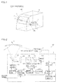
- the projector 100 includes a projector body 1, a beam receiving portion 2, a screen 3 and a case 4, as shown in Fig. 1 .
- This projector 100 is a rear projection type projector (rear projector) projecting an image 31 from behind the screen 3.
- the projector 100 is configured to accept an operation performed on the image 31 with an operating element such as a touch pen 5.
- the screen 3 is an example of the "projection area” in the present invention
- the touch pen 5 is an example of the "detection object" in the present invention.
- the projector body 1 includes a main CPU 101, an operation portion 102, three laser beam sources 103, 104 and 105, two polarizing beam splitters 106 and 107, a lens 108, an image projection portion 109, a position acquisition CPU 110, a picture processing portion 111, a beam source control portion 112, an LD (Laser Diode) driver 113, a mirror control portion 114 and a mirror driver 115, as shown in Fig. 2 .
- the image projection portion 109 has an MEMS (Micro Electro Mechanical System) mirror 109a.
- the main CPU 101 is an example of the "control portion” in the present invention.
- the laser beam sources 103 to 105 are examples of the "laser beam generation portion" in the present invention, and the MEMS mirror 109a is an example of the "scanning portion" in the present invention.
- the beam receiving portion 2 is configured to receive (detect) laser beams reflected by the touch pen 5, as shown in Fig. 2 .
- the beam receiving portion 2 is connected to the position acquisition CPU 110, and configured to transmit beam receiving information indicating that the same has received the laser beams to the position acquisition CPU 110.
- the screen 3 is configured to transmit and diffuse the laser beams projected by the projector body 1 from behind (from the side of the projector body 1) frontward (toward the side of the touch pen 5). More specifically, the screen 3 includes a plurality of diffusion lenses for diffusing the laser beams.
- the screen 3 is mainly made of resin such as vinyl chloride, and configured to be semitransparent for transmitting the laser beams.
- the screen 3 is in the form of a curved surface in conformity to a curved surface of the case 4.
- the case 4 is provided to cover the projector body 1 and the beam receiving portion 2.
- the screen 3 is arranged on a front side of the case 4.
- the main CPU 101 is configured to control the respective portions of the projector 100.
- the operation portion 102 is provided for accepting an operation of turning on the projector 100, an operation of changing the resolution of the image 31 and the like.
- the laser beam source 103 is configured to apply a blue laser beam to the MEMS mirror 109a through the polarizing beam splitter 106 and the lens 108.
- the laser beam sources 104 and 105 are configured to apply green and red laser beams to the MEMS mirror 109a through the beam splitters 107 and 106 and the lens 108 respectively.
- the image projection portion 109 is configured to project the image 31 (see Fig. 1 ) on the screen 3.
- This image projection portion 109 is a rear projection type image projection portion projecting the image 31 from behind the screen 3. More specifically, the image projection portion 109 is so configured that the MEMS mirror 109a thereof scans the laser beams applied from the laser beam sources 103 to 105 and projects the image 31 from behind the screen 3 (from inside the case 4).
- the MEMS mirror 109a is configured to scan the laser beams along two axes in the horizontal direction and the vertical direction. Further, the MEMS mirror 109a is configured to scan the horizontal direction at a high speed by resonance driving and to scan the vertical direction at a low speed by DC driving.
- the position acquisition CPU 110 is configured to acquire the position of the touch pen 5 on the basis of time information as to the time when the beam receiving portion 2 has received the reflected laser beams and scanning loci of the laser beams. More specifically, the position acquisition CPU 110 acquires the position (coordinates) of the touch pen 5 corresponding to the image 31 by specifying positions of the detected laser beams scanned with respect to the image 31 on the basis of an elapsed time up to the detection of the laser beams from horizontal synchronizing signals and the scanning loci of the laser beams.
- the picture processing portion 111 is configured to control projection of a picture on the basis of an externally received picture signal. More specifically, the picture processing portion 111 is configured to control driving of the MEMS mirror 109a through the mirror control portion 114 and to control the application of the laser beams by the laser beam sources 103 to 105 through the beam source control portion 112 on the basis of the externally received picture signal.
- the beam source control portion 112 is configured to control the application of the laser beams by the laser beam sources 103 to 105 by controlling the LD driver 113 on the basis of the control by the picture processing portion 111. More specifically, the beam source control portion 112 is configured to perform control of making the laser beam sources 103 to 105 apply the laser beams of colors corresponding to respective pixels of the image 31 in timing with the scanning of the MEMS mirror 109a.
- the mirror control portion 114 is configured to control driving of the MEMS mirror 109a by controlling the mirror driver 115 on the basis of the control by the picture processing portion 111.
- the main CPU 101 is configured to acquire a moving state of the touch pen 5 from receptive results of the laser beams received by the beam receiving portion 2. More specifically, the main CPU 101 is configured to detect the position of the touch pen 5 with respect to the projected image 31 by acquiring the scanning positions of the laser beams scanned by the MEMS mirror 109a at the timing of receiving the laser beams reflected by the touch pen 5 and to detect movement of the touch pen 5 on the basis of change in the scanning positions of the laser beams at the timing of receiving the laser beams reflected by the touch pen 5.
- the main CPU 101 is configured to calculate a moving speed of the touch pen 5 from the receptive results of the laser beams received by the beam receiving portion 2 and to acquire the change in the moving state of the touch pen 5 on the basis of the change in the moving speed of the touch pen 5. More detailedly, the main CPU 101 calculates the moving speed of the touch pen 5 from temporal change in the position of the touch pen 5 corresponding to the image 31 acquired by the position acquisition CPU 110. Then, the main CPU 101 acquires the change in the moving state of the touch pen 5 on the basis of the change in the moving speed of the touch pen 5.
- the main CPU 101 is configured to detect an operation (touch operation) performed on the projected image 31 with the touch pen 5 on the basis of the moving state of the touch pen 5. More specifically, the main CPU 101 is configured to detect the operation performed on the projected image 31 with the touch pen 5 on the basis of the change in the moving state of the touch pen 5 acquired from the receptive results of the laser beams received by the beam receiving portion 2.
- the main CPU 101 is configured to determine that the operation with the touch pen 5 has been performed on a position of the projected image 31 corresponding to a position where the movement of the touch pen 5 has stopped when the movement of the touch pen 5 has stopped on the basis of the change in the moving state of the touch pen 5 acquired from the receptive results of the laser beams received by the beam receiving portion 2.
- the main CPU 101 is configured to determine that the touch pen 5 stands still when the position of the touch pen 5 with respect to the projected image 31 remains unchanged in a prescribed range for at least a prescribed time. When the position on the image 31 where the touch pen 5 is detected remains unchanged for at least 0.5 seconds in the range of prescribed pixels, for example, the main CPU 101 determines that the touch pen 5 stands still.
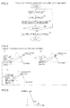
- the main CPU 101 When controlling the projection portion 109 to start projecting the image 31, the main CPU 101 brings the beam receiving portion 2 into a state capable of receiving the laser beams.
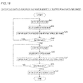
- the main CPU 110 acquires coordinates (position information) of the touch pen 5 with respect to the image 31 acquired by the position acquisition CPU 110 on the basis of receptive information in the beam receiving portion 2 at a step S2. Then, the main CPU 101 compares the coordinates (position information) of the touch pen 5 in a current frame of the image 31 with those in a preceding frame at a step S3.
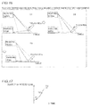
- the position of the touch pen 5 moves in a direction approaching the screen 3 as shown at A1 and A2 in Fig. 4 , for example, scanning positions (coordinates with respect to the image 31) of the laser beams reflected by the touch pen 5 move on the screen 3 (on the image 31).
- the main CPU 101 determines whether or not the coordinates of the touch pen 5 are moving. Further, the main CPU 101 calculates the moving speed of the touch pen 5. When determining that the touch pen 5 is moving (the moving speed is not zero), the main CPU 101 returns to the step S1. When determining that the touch pen 5 is not moving (the moving speed is zero), on the other hand, the main CPU 101 determines that the image 31 has been touched with the touch pen 5 at a step S5. In other words, the main CPU 5 determines that the image 31 has been touched with the touch pen 5 on a position of the projected image 31 corresponding to a position where the movement of the touch pen 5 has stopped. The main CPU 101 repeats the processing at the steps S1 to S5 during the projection.
- the main CPU 101 determines that an operation (touch operation) with the touch pen 5 has been performed on the position of the projected image 31 corresponding to the position where the touch pen 5 has stopped when detecting that the touch pen 5 has continuously moved in the direction approaching the screen 3 (the projected image 31) and stopped, as shown in Fig. 4 . More specifically, the main CPU 101 determines that the touch operation with the touch pen 5 has been performed when detecting that the touch pen 5 has linearly moved to a touch position and stopped. Further, the main CPU 101 determines that the touch operation with the touch pen 5 has been performed when the moving speed of the touch pen 5 has reached zero (corresponding to A3 in Figs. 4 and 5 ), as shown in Fig. 5 .
- the direction where the speed is positive indicates that approaching the screen 3.
- the direction approaching the screen 3 is an example of the "third direction" in the present invention.
- the projector 100 is provided with the main CPU 110 acquiring the moving state of the touch pen 5 from the receptive results of the laser beams received by the beam receiving portion 2 and detecting the operation (touch operation) performed on the projected image 31 with the touch pen 5 on the basis of the moving state of the touch pen 5 so that the same can detect the operation performed with the touch pen 5 in consideration of moving states of the touch pen 3 before and after the operation therewith, whereby the main CPU 101 can be inhibited from detecting the operation performed with the touch pen 5 on a false position when the reflected laser beams are received while the touch pen 5 approaches an operating position.
- the main CPU 101 can precisely detect the operation performed on the projected image 31 with the touch pen 5.
- the main CPU 101 is configured to detect the operation (touch operation) performed on the projected image 31 with the touch pen 5 on the basis of the change in the moving state of the touch pen 5 acquired from the receptive results of the laser beams received by the beam receiving portion 2.
- the main CPU 101 can detect the operation performed on the projected image 31 with the touch pen 5 on the basis of the change in the moving state of the touch pen 5 whose moving speed or direction changes before and after the operation, whereby the same can easily precisely detect the operation performed with the touch pen 5.
- the main CPU 101 is configured to determine that the operation (touch operation) with the touch pen 5 has been performed on the position of the projected image 31 corresponding to the position where the movement of the touch pen 5 has stopped when the movement of the touch pen 5 has stopped on the basis of the change in the moving state of the touch pen 5 acquired from the receptive results of the laser beams received by the beam receiving portion 2.
- the main CPU 101 can detect the operation when the touch pen 5 has stopped on the operating position without detecting the operation in the process of the movement of the touch pen 5 toward the operating position, whereby the same can be easily inhibited from detecting the operation performed with the touch pen 5 on a false position in the process of the movement thereof.
- the main CPU 101 is configured to calculate a moving speed of the touch pen 5 from the receptive results of the laser beams received by the beam receiving portion 2, to acquire the change in the moving state of the touch pen 5 on the basis of the change in the moving speed of the touch pen 5 and to determine that the operation (touch operation) with the touch pen 5 has been performed on the position of the projected image 31 corresponding to the position where the movement of the touch pen 5 has stopped when the movement of the touch pen 5 has stopped.
- the main CPU 101 can easily determine that the movement of the touch pen 5 has stopped on the basis of the moving speed thereof, whereby the same can more easily precisely detect the operation performed with the touch pen 5.
- the main CPU 101 is configured to determine that the touch pen 5 stands still when the position of the touch pen 5 with respect to the projected image 31 remains unchanged in the prescribed range for at least the prescribed time.
- the main CPU 101 can recognize that the touch pen 5 has been stopped for the operation while allowing an error, whereby the same can detect the operation performed with the touch pen 5 to accord with the user's operational intention.
- the main CPU 101 is configured to detect the position of the touch pen 5 with respect to the projected image 31 by acquiring the scanning positions of the laser beams scanned by the MEMS mirror 109a at the timing of receiving the laser beams reflected by the touch pen 5 and to detect the movement of the touch pen 5 on the basis of the change in the scanning positions of the laser beams at the timing of receiving the lase beams reflected by the touch pen 5.
- the main CPU 101 can easily detect the movement of the touch pen 5 by easily acquiring the position thereof.
- the main CPU 101 is configured to determine that the operation (touch operation) with the touch pen 5 has been performed on the position of the projected image 31 corresponding to the position where the touch pen 5 has stopped when detecting that the touch pen 5 has continuously moved in the direction approaching the screen 3 and stopped from the receptive results of the laser beams received by the beam receiving portion 2.
- the main CPU 101 determines that the operation with the touch pen 5 has been performed when the touch pen 5 has continuously moved in the direction approaching the screen 3 toward the operating position and stopped, whereby the same can be easily inhibited from detecting the operation performed with the touch pen 5 on a false position in the process of the movement thereof.
- the image projection portion 109 includes the projection type image projection portion projecting the image 31 from behind the screen 3.
- the main CPU 101 can be inhibited from detecting the operation performed with the touch pen 5 on a false position in the process of the movement thereof to precisely detect the operation performed with the touch pen 5 also in a case where laser beams reflected on positions separating from a screen 3 are easily detected in such a rear projector that a touch pen 5 is arranged on a side of the screen 3 opposite to a side where the laser beams are applied.
- FIG. 1 A modification of the first embodiment is now described. While the rear projection type projector 100 is employed in the aforementioned first embodiment as shown in Fig. 1 , a front projection type projector 200 is employed in the modification thereof, as shown in Fig. 6 .
- the projector 200 is configured to be used in a state arranged on a table 3a, as shown in Fig. 6 . Further, the projector 200 is configured to project an image 31a on the upper surface of a projection area such as the table 3a.
- the table 3a is an example of the "projection area" in the present invention.
- the projector 200 includes a main CPU 101, an operation portion 102, three laser beam sources 103, 104 and 105, two polarizing beam splitters 106 and 107, a lens 108, an image projection portion 109, a position acquisition CPU 110, a picture processing portion 111, a beam source control portion 112, an LD (Laser Diode) driver 113, a mirror control portion 114 and a mirror driver 115, as shown in Fig. 7 . Further, the projector 200 integrally includes a beam receiving portion 2a.
- the image projection portion 109 has an MEMS mirror 109a.
- the main CPU 101 is an example of the "control portion” in the present invention.
- the laser beam sources 103 to 105 are examples of the "laser beam generation portion” in the present invention
- the MEMS mirror 109a is an example of the "scanning portion” in the present invention.
- the main CPU 101 is configured to determine that an operation with a touch pen 5 has been performed on a position of the projected image 31a corresponding to a position where movement of the touch pen 5 has stopped when the movement of the touch pen 5 has stopped on the basis of change in a moving state of the touch pen 5 acquired from receptive results of laser beams received by the beam receiving portion 2a, as shown in Fig. 8 .
- the remaining structure of the modification of the first embodiment is similar to that of the aforementioned first embodiment.
- a main CPU 101 detects a touch operation on the basis of a moving direction of a touch pen 5, dissimilarly to the first embodiment having the main CPU 101 detecting the touch operation through the stopping of the touch pen 5.
- a projector 100 according to the second embodiment of the present invention is constituted of a rear projection type projector similarly to the first embodiment, as shown in Figs. 1 and 2 .
- the main CPU 101 is configured to determine that the operation with the touch pen 5 has been performed on a position of a projected image 31 corresponding to a position where the touch pen 5 has started moving in a direction separating from a screen 3 when detecting that the touch pen 5 has moved in a direction approaching the screen 3 (the projected image 31), stopped and started moving in the direction separating from the screen 3 (the projected image 31) on the basis of change in a moving state of the touch pen 5 acquired from receptive results of laser beams received by a beam receiving portion 2.
- the direction approaching the screen 3 is an example of the "first direction” in the present invention
- the direction separating from the screen 3 is an example of the "second direction" in the present invention.
- the main CPU 101 is configured to calculate a moving speed of the touch pen 5 from the receptive results of the laser beams received by the beam receiving portion 2, to acquire the change in the moving state of the touch pen 5 on the basis of change in the moving speed of the touch pen 5, and to determine that the operation with the touch pen 5 has been performed on the position of the projected image 31 corresponding to the position where the touch pen 5 has started moving in the direction separating from the screen 3 when detecting that the touch pen 5 has moved in the direction approaching the screen 3, stopped and started moving in the direction separating from the screen 3.
- the main CPU 101 When controlling the projection portion 109 to start projecting the image 31, the main CPU 101 brings the beam receiving portion 2 into a state capable of receiving the laser beams.
- the main CPU 110 acquires coordinates (position information) of the touch pen 5 with respect to the image 31 acquired by the position acquisition CPU 110 on the basis of receptive information in the beam receiving portion 2 at a step S12. Then, the main CPU 101 compares the coordinates (position information) of the touch pen 5 in a current frame of the image 31 with those in a preceding frame at a step S13.
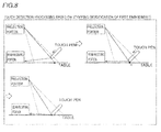
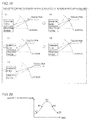
- the position of the touch pen 5 moves in the direction approaching the screen 3 as shown at B1 and B2 in Fig. 10 , for example, scanning positions (coordinates with respect to the image 31) of the laser beams reflected by the touch pen 5 move on the screen 3 (on the image 31).
- the main CPU 101 determines whether or not the coordinates of the touch pen 5 are moving. Further, the main CPU 101 calculates the moving speed of the touch pen 5. When determining that the touch pen 5 is moving (the moving speed is not zero), the main CPU 101 calculates the moving direction of the touch pen 5 at a step S15. More specifically, the main CPU 101 determines whether the touch pen 5 has moved in the direction approaching the screen 3 or in a direction separating from the screen 3. Thereafter the main CPU 101 returns to the step S11. When determining that the touch pen 5 is not moving (the moving speed is zero), on the other hand, the main CPU 101 advances to a step S16.
- the main CPU 101 When determining that the beam receiving portion 2 has detected the laser beams reflected by the touch pen 5 at the step S16, the main CPU 101 acquires the coordinates (position information) of the touch pen 5 with respect to the image 31 acquired by the position acquisition CPU 110 on the basis of the receptive information in the beam receiving portion 2 at a step S17. Then, the main CPU 101 compares the coordinates (position information) of the touch pen 5 in the current frame of the image 31 with those in the preceding frame at a step S18.
- the main CPU 101 determines whether or not the coordinates of the touch pen 5 are moving. Further, the main CPU 101 calculates the moving speed of the touch pen 5. When determining that the touch pen 5 is moving (the moving speed is not zero), the main CPU 101 returns to the step S16. When determining that the touch pen 5 is not moving (the moving speed is zero), on the other hand, the main CPU 101 advances to a step S20.
- the main CPU 101 calculates the moving direction of the touch pen 5. More specifically, the main CPU 101 determines whether the touch pen 5 has moved in the direction approaching the screen 3 or in the direction separating from the screen 3. At a step S21, the main CPU 101 determines whether or not the moving direction of the touch pen 5 before stopping and the current moving direction are opposite to each other. In other words, the main CPU 101 determines whether or not the touch pen 5 has moved in the direction approaching the screen 3, stopped and started moving in the direction separating from the screen 3. If the moving direction of the touch pen 5 is not opposite to the moving direction before the stopping (if the directions are substantially identical to each other), the main CPU 101 returns to the step S11. If the moving direction of the touch pen 5 is opposite to the moving direction before the stopping, on the other hand, the main CPU 101 determines that a touch operation has been performed on the image 31 with the touch pen 5 at a step S22.
- the main CPU 101 determines that the operation with the touch pen 5 has been performed on a position of the projected image 31 corresponding to a position (corresponding to B4 in Fig. 10 ) where the touch pen 5 has started moving in the direction separating from the screen 3 when detecting that the touch pen 5 has moved in the direction approaching the screen 3 as shown at B1 and B2 in Fig. 10 , stopped as shown at B3 in Fig. 10 and started moving in the direction separating from the screen 3 as shown at B4 in Fig. 10 .
- the main CPU 101 determines that the touch operation has been performed on the image 31 with the touch pen 5 when the speed of the touch pen 5 has reached a level (negative value) in the direction separating from the screen 3 from a level (positive value) in the direction approaching the screen 3 after temporary stopping, as shown in Fig. 11 .
- the main CPU 101 repeats the processing at the steps S11 to S22 during the projection.
- the remaining structure of the second embodiment is similar to that of the aforementioned first embodiment.
- the projector 100 is provided with the main CPU 101 acquiring the moving state of the touch pen 5 from the receptive results of the laser beams received by the beam receiving portion 2 and detecting the operation (touch operation) performed on the projected image 31 with the touch pen 5 on the basis of the moving state of the touch pen 5 similarly to the aforementioned first embodiment, whereby the main CPU 101 can precisely detect the operation performed on the projected image 31 with the touch pen 5.
- the main CPU 101 is configured to determine that the operation (touch operation) with the touch pen 5 has been performed on the position of the projected image 31 corresponding to the position where the touch pen 5 has started moving in the direction separating from the screen 3 when detecting that the touch pen 5 has moved in the direction approaching the screen 3, stopped and started moving in the direction separating from the screen 3 on the basis of the change in the moving state of the touch pen 5 acquired from the receptive results of the laser beams received by the beam receiving portion 2.
- the main CPU 101 can detect the operation performed on the projected image 31 with the touch pen 5 on the basis of a series of moving states of the touch pen 5 approaching the projected image 31 by moving in the direction approaching the screen 3, stopping and separating from the projected image 31 by moving in the direction separating from the screen 3, whereby the same can detect the operation performed with the touch pen 5 on a temporarily stopped position when the touch pen 5 has temporarily stopped and started moving to an operating position again in the process of moving toward the operating position, for example. Consequently, the main CPU 101 can more precisely detect the operation performed with the touch pen 5.
- the main CPU 101 is configured to calculate a moving speed of the touch pen 5 from the receptive results of the laser beams received by the beam receiving portion 2, to acquire the change in the moving state of the touch pen 5 on the basis of the change in the moving speed of the touch pen 5, and to determine that the operation (touch operation) with the touch pen 5 has been performed on the position of the projected image 31 corresponding to the position where the touch pen 5 has started moving in the direction separating from the screen 3 when detecting that the touch pen 5 has moved in the direction approaching the screen 3, stopped and started moving in the direction separating from the screen 3.
- the main CPU 101 can easily determine that the touch pen 5 has moved in the direction approaching the screen 3, stopped and started moving in the direction separating from the screen 3 on the basis of the moving speed of the touch pen 5, whereby the same can more easily precisely detect the operation performed with the touch pen 5.
- FIG. 1 A modification of the second embodiment is now described. While the rear projection type projector 100 is employed in the aforementioned second embodiment as shown in Fig. 1 , a front projection type projector 200 is employed in the modification thereof similarly to the modification of the first embodiment, as shown in Fig. 6 .
- a main CPU 101 is configured to calculate a moving speed of a touch pen 5 from receptive results of laser beams received by a beam receiving portion 2a, to acquire change in a moving state of the touch pen 5 on the basis of change in the moving speed of the touch pen 5 and to determine that an operation with the touch pen 5 has been performed on a position of a projected image 31a corresponding to a position where the touch pen 5 has started moving in a direction separating from a table 3a when detecting that the touch pen 5 has moved in a direction approaching the table 3a, stopped and started moving in the direction separating from the table 3a.
- a main CPU 101 detects a moving state of a touch pen 5 on the basis of a quantity of laser beams received by a beam receiving portion 2, dissimilarly to the first and second embodiments each having the main CPU 101 detecting the moving state of the touch pen 5 on the basis of the moving speed thereof.
- a projector 100 according to the third embodiment of the present invention is constituted of a rear projection type projector as shown in Figs. 1 and 2 , similarly to the first embodiment.
- the main CPU 101 is configured to determine that an operation with the touch pen 5 has been performed on a position of a projected image 31 corresponding to a position where movement of the touch pen 5 has stopped when the movement has stopped on the basis of change in a moving state of the touch pen 5 acquired from receptive results of the laser beams received by the beam receiving portion 2.
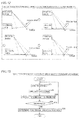
- the main CPU 101 is configured to acquire the change in the moving state of the touch pen 5 on the basis of change in the quantity of the laser beams received by the beam receiving portion 2 and to determine that the operation with the touch pen 5 has been performed when the change in the quantity of the received laser beams has stopped in a case where the quantity of the received laser beams has increased and the change in the quantity of the received laser beams has stopped, as shown in Fig. 15 .
- the main CPU 101 is configured to measure the quantity of laser beams reflected by the touch pen 5 and received by the beam receiving portion 2 every pixel in one frame of the projected image 31. In this case, the main CPU 101 may measure a peak value or an integrated value of the quantity of the received laser beams.
- the main CPU 101 When controlling the projection portion 109 to start projecting the image 31, the main CPU 101 brings the beam receiving portion 2 into a state capable of receiving the laser beams.
- the main CPU 101 stores the quantity of the laser beams received by the beam receiving portion 2 at a step S32.
- the main CPU 101 compares the quantity of the received laser beams in a current frame of the image 31 with that in a preceding frame.
- the main CPU 101 determines whether or not the quantity of the received laser beams in the current frame has increased as compared with the preceding frame. When determining that the quantity of the received laser beams has increased, the main CPU 101 returns to the step S31. When determining that increase in the quantity of the received laser beams has stopped, on the other hand, the main CPU 101 determines that a touch operation has been performed on the image 31 with the touch pen 5 at a step S35. In other words, the main CPU 101 determines that the operation with the touch pen 5 has been performed when the change in the quantity of the received laser beams has stopped in a case where the quantity of the received laser beams has increased and the change in the quantity of the received laser beams has stopped (corresponding to C3 in Figs. 14 and 15 ), as shown in Fig. 15 . The main CPU 101 repeats the processing at the steps S31 to S35 during the projection.
- the remaining structure of the third embodiment is similar to that of the aforementioned first embodiment.
- the projector 100 is provided with the main CPU 101 acquiring the moving state of the touch pen 5 from the receptive results of the laser beams received by the beam receiving portion 2 and detecting the operation (touch operation) performed on the projected image 31 with the touch pen 5 on the basis of the moving state of the touch pen 5, whereby the main CPU 101 can precisely detect the operation performed on the projected image 31 with the touch pen 5.
- the main CPU 101 is configured to acquire the change in the moving state of the touch pen 5 on the basis of the change in the quantity of the laser beams received by the beam receiving portion 2 and to determine that the operation (touch operation) with the touch pen 5 has been performed when the change in the quantity of the received laser beams has stopped in the case where the quantity of the received laser beams has increased and the change in the quantity of the received laser beams has stopped.
- the main CPU 101 can easily determine that movement of the touch pen 5 has stopped on the basis of that the change in the quantity of the received laser beams has stopped, whereby the same can more easily precisely detect the operation performed with the touch pen 5.
- FIG. 1 A modification of the third embodiment is now described. While the rear projection type projector 100 is employed in the aforementioned third embodiment as shown in Fig. 1 , a front projection type projector 200 is employed in the modification thereof similarly to the modification of the first embodiment, as shown in Fig. 6 .
- a main CPU 101 is configured to acquire change in a moving state of a touch pen 5 on the basis of change in the quantity of laser beams received by a beam receiving portion 2a and to determine that an operation with the touch pen 5 has been performed when the change in the quantity of the received laser beams has stopped in a case where the quantity of the received laser beams has increased and the change in the quantity of the received laser beams has stopped (corresponding to D3 in Figs. 16 and 17 ), as shown in Figs. 16 and 17 .
- a main CPU 101 detects a touch operation on the basis of change in the quantity of laser beams received by a beam receiving portion 2, dissimilarly to the third embodiment having the main CPU 101 detecting the touch operation on the basis of the stopping of the change in the quantity of the laser beams received by the beam receiving portion 2.
- a projector 100 according to the fourth embodiment of the present invention is constituted of a rear projection type projector as shown in Figs. 1 and 2 , similarly to the first embodiment.
- the main CPU 101 is configured to determine that an operation with a touch pen 5 has been performed on a position of a projected image 31 corresponding to a position where the touch pen 5 has started moving in a direction separating from a screen 3 when detecting that the touch pen 5 has moved in a direction approaching the screen 3, stopped and started moving in the direction separating from the screen 3 on the basis of change in a moving state of the touch pen 5 acquired from receptive results of the laser beams received by the beam receiving portion 2.
- the main CPU 101 is configured to acquire the change in the moving state of the touch pen 5 on the basis of change in the quantity of the laser beams received by the beam receiving portion 2 and to determine that the operation with the touch pen 5 has been performed when the quantity of the received laser beams has started decreasing in a case where the quantity of the received laser beams has increased, the change in the quantity of the received laser beams has stopped and the quantity of the received laser beams has started decreasing as shown in Fig. 20 .
- the main CPU 101 When controlling a projection portion 109 to start projecting the image 31, the main CPU 101 brings the beam receiving portion 2 into a state capable of receiving the laser beams.
- the main CPU 101 stores the quantity of the laser beams received by the beam receiving portion 2 at a step S42.
- the main CPU 101 compares the quantity of the received laser beams in a current frame of the image 31 with that in a preceding frame.
- the main CPU 101 determines whether or not the quantity of the received laser beams in the current frame has increased as compared with the preceding frame. When determining that the quantity of the received laser beams has increased, the main CPU 101 returns to the step S41. When determining that increase in the quantity of the received laser beams has stopped, on the other hand, the main CPU 101 advances to a step S45.
- the main CPU 101 When determining that the beam receiving portion 2 has detected the laser beams reflected by the touch pen 5 at the step S45, the main CPU 101 stores the quantity of the laser beams received by the beam receiving portion 2 at a step S46. At a step S47, the main CPU 101 compares the quantity of the received laser beams in the current frame of the image 31 with that in the preceding frame.
- the main CPU 101 determines whether or not the quantity of the received laser beams has decreased as compared with that in the preceding frame. When determining that the quantity of the received laser beams has not decreased (the quantity of the received laser beams has remained unchanged), the main CPU 101 returns to the step S45. When determining that the quantity of the received laser beams has decreased, on the other hand, the main CPU 101 determines that the touch operation has been performed on the image 31 with the touch pen 5 at a step S49.
- the main CPU 101 determines that the operation with the touch pen 5 has been performed when the quantity of the received laser beams has started decreasing in a case where the quantity of the received laser beams has increased, change in the quantity of the received laser beams has stopped as shown at E3 in Fig. 20 and the quantity of the received laser beams has started decreasing, as shown in Fig. 20 .
- the main CPU 101 repeats the processing at the steps S41 to S49 during the projection.
- the remaining structure of the fourth embodiment is similar to that of the aforementioned first embodiment.
- the projector 100 is provided with the main CPU 101 acquiring the moving state of the touch pen 5 from the receptive results of the laser beams received by the beam receiving portion 2 and detecting the operation (touch operation) performed on the projected image 31 with the touch pen 5 on the basis of the moving state thereof similarly to the aforementioned first embodiment, whereby the main CPU 101 can precisely detect the operation performed on the projected image 31 with the touch pen 5.
- the main CPU 101 is configured to acquire the change in the moving state of the touch pen 5 on the basis of change in the quantity of the laser beams received by the beam receiving portion 2 and to determine that the operation with the touch pen 5 has been performed when the quantity of the received laser beams has started decreasing in the case where the quantity of the received laser beams has increased, the change in the quantity of the received laser beams has stopped and the quantity of the received laser beams has started decreasing.
- the main CPU 101 can easily determine that the touch pen 5 has moved in the direction approaching the screen 3, stopped and started moving in the direction separating from the screen 3 on the basis of that the quantity of the received laser beams has increased, the change in the quantity of the received laser beams has stopped and the quantity of the received laser beams has started decreasing, whereby the same can more easily precisely detect the operation performed with the touch pen 5.
- FIG. 1 A modification of the fourth embodiment is now described. While the rear projection type projector 100 is employed in the aforementioned fourth embodiment as shown in Fig. 1 , a front projection type projector 200 is employed in the modification thereof similarly to the modification of the first embodiment, as shown in Fig. 6 .
- a main CPU 101 is configured to acquire change in a moving state of a touch pen 5 on the basis of change in the quantity of laser beams received by a beam receiving portion 2 and to determine that an operation with the touch pen 5 has been performed when the quantity of the received laser beams has started decreasing in a case where the quantity of the received laser beams has increased (corresponding to F1 and F2 in Figs. 21 and 22 ), the change in the quantity of the received laser beams has stopped (corresponding to F3 in Figs. 21 and 22 ) and the quantity of the received laser beams has started decreasing (corresponding to F4 in Figs. 21 and 22 ), as shown in Figs. 21 and 22 .
- the remaining structure of the modification of the fourth embodiment is similar to that of the aforementioned fourth embodiment.
- the rear projection type projector may include a projector such as a rear projection television according to the present invention.
- the image projection portion projects the image on the table as the projection area in each of the modifications of the aforementioned first to fourth embodiments
- the present invention is not restricted to this.
- the image projection portion may alternatively project the image on a projection area such as a screen, or may project the image on at least two projection areas such as a table and a screen while dividing laser beams.
- the screen is in the form of a curved surface in each of the aforementioned first to fourth embodiments, the present invention is not restricted to this. According to the present invention, the screen may alternatively be in the form of a planar surface, or may have a stereoscopic shape (such as a spherical shape, for example).
- the present invention is not restricted to this.
- the projector may alternatively integrally include the beam receiving portion and the image projecting portion.
- the touch pen is employed as the detection object in each of the aforementioned first to fourth embodiments, the present invention is not restricted to this. According to the present invention, a finger or a hand may alternatively be employed as the detection object, so far as the same can reflect laser beams.
- the laser beam source applies the red, green and blue laser beams for projecting the image so that the main CPU acquires the position (coordinates) of the touch pen as the detection object in each of the aforementioned first to fourth embodiments
- the present invention is not restricted to this.
- the main CPU may alternatively acquire the position (coordinates) of the detection object with a laser beam (invisible laser beam) such as an infrared laser beam, dedicated to detection, not contributing to image projection.
- control portion main CPU
- the present invention is not restricted to this.
- the control portion may alternatively perform event-driven processing every event.
- the control portion may perform complete event-driven processing, or a combination of event-driven processing and flow-driven processing.
Landscapes
- Engineering & Computer Science (AREA)
- Physics & Mathematics (AREA)
- General Engineering & Computer Science (AREA)
- Theoretical Computer Science (AREA)
- Multimedia (AREA)
- Signal Processing (AREA)
- General Physics & Mathematics (AREA)
- Optics & Photonics (AREA)
- Human Computer Interaction (AREA)
- Mechanical Optical Scanning Systems (AREA)
- Transforming Electric Information Into Light Information (AREA)
- Control Of Indicators Other Than Cathode Ray Tubes (AREA)
Abstract
Description
- The present invention relates to a projector, and more particularly, it relates to a projector including a laser beam generation portion.
- A projector including a laser beam generation portion is known in general, as disclosed in Japanese Patent Laying-Open No.
2009-258569 - The aforementioned Japanese Patent Laying-Open No.
2009-258569 - In the projector module (projector) according to the aforementioned Japanese Patent Laying-Open No.
2009-258569 - The present invention has been proposed in order to solve the aforementioned problem, and an object of the present invention is to provide a projector capable of precisely detecting an operation performed on a projected image with a detection object.
- A projector according to an aspect of the present invention includes a laser beam generation portion outputting a laser beam, an image projection portion including a scanning portion scanning the laser beam and projecting an image on a projection area, a beam receiving portion receiving the laser beam reflected by a detection object and a control portion acquiring a moving state of the detection object from a receptive result of the laser beam received by the beam receiving portion and detecting an operation performed on the projected image with the detection object on the basis of the moving state of the detection object.
- As hereinabove described, the projector according to the aspect of the present invention is provided with the control portion acquiring the moving state of the detection object from the receptive result of the laser beam received by the beam receiving portion and detecting the operation performed on the projected image with the detection object on the basis of the moving state of the detection object so that the same can detect the operation performed with the detection object in consideration of moving states of the detection object before and after the operation performed therewith, whereby the control portion can be inhibited from detecting the operation performed with the detection object on a false position when the reflected laser beam is received while the detection object approaches an operating position. Thus, the control portion can precisely detect the operation such as a touch operation performed on the projected image with the detection object.
- In the aforementioned projector according to the aspect, the control portion is preferably configured to detect the operation performed on the projected image with the detection object on the basis of change in the moving state of the detection object acquired from the receptive result of the laser beam received by the beam receiving portion. According to this structure, the control portion can detect the operation performed on the projected image with the detection object on the basis of the change in the moving state of the detection object whose moving speed or direction changes before and after the operation, whereby the same can easily precisely detect the operation performed with the detection object.
- In the aforementioned structure of detecting the operation performed on the projected image with the detection object on the basis of the change in the moving state of the detection object, the control portion is preferably configured to determine that the operation with the detection object has been performed on a position of the projected image corresponding to a position where movement of the detection object has stopped when determining that the movement of the detection object has stopped on the basis of the change in the moving state of the detection object acquired from the receptive result of the laser beam received by the beam receiving portion. According to this structure, the control portion can detect the operation when the detection object has stopped on the operating position without detecting the operation in the process of the movement of the detection object to the operating position, whereby the same can be easily inhibited from detecting the operation performed with the detection object on a false position in the process of the movement thereof.
- In the aforementioned structure of detecting the operation performed on the projected image with the detection object on the basis of the change in the moving state of the detection object, the control portion is preferably configured to calculate a moving speed of the detection object from the receptive result of the laser beam received by the beam receiving portion, to acquire the change in the moving state of the detection object on the basis of change in the moving speed of the detection object, and to determine that the operation with the detection object has been performed on a position of the projected image corresponding to a position where movement of the detection object has stopped when the movement of the detection object has stopped. According to this structure, the control portion can easily determine that the movement of the detection object has stopped on the basis of the moving speed thereof, whereby the same can more easily precisely detect the operation performed with the detection object.
- In the aforementioned structure of determining that the operation with the detection object has been performed on the position of the projected image corresponding to the position where the movement of the detection object has stopped, the control portion is preferably configured to determine that the detection object stands still when the position of the detection object with respect to the projected image remains unchanged in a prescribed range for at least a prescribed time. According to this structure, the control portion can recognize that the detection object has been stopped for the operation while allowing an error, whereby the same can detect the operation performed with the detection object to accord with the user's operational intention.
- In the aforementioned structure of detecting the operation performed on the projected image with the detection object on the basis of the change in the moving state of the detection object, the control portion is preferably configured to acquire a scanning position of the laser beam scanned by the scanning portion at a timing of receiving the laser beam reflected by the detection object, to detect a position of the detection object with respect to the projected image and to detect movement of the detection object on the basis of change in the scanning position of the laser beam at the timing of receiving the laser beam reflected by the detection object. According to this structure, the control portion can easily detect the movement of the detection object by easily acquiring the position thereof.
- In the aforementioned structure of detecting the operation performed on the projected image with the detection object on the basis of the change in the moving state of the detection object, the control portion is preferably configured to acquire the change in the moving state of the detection object on the basis of change in the quantity of the laser beam received by the beam receiving portion and to determine that the operation with the detection object has been performed when the change in the quantity of the received laser beam has stopped in a case where the quantity of the received laser beam has increased and the change in the quantity of the received laser beam has stopped. According to this structure, the control portion can easily determine that the movement of the detection object has stopped on the basis of that the change in the quantity of the received laser beam has stopped, whereby the same can more easily precisely detect the operation performed with the detection object.
- In the aforementioned structure of detecting the operation performed on the projected image with the detection object on the basis of the change in the moving state of the detection object, the control portion is preferably configured to determine that the operation with the detection object has been performed on a position of the projected image corresponding to a position where the detection object has started moving in a second direction when detecting that the detection object has moved in a first direction, stopped and started moving in the second direction opposite to the first direction on the basis of the change in the moving state of the detection object acquired from the receptive result of the laser beam received by the beam receiving portion. According to this structure, the control portion can detect the operation performed on the projected image with the detection object on the basis of a series of moving states of the detection object approaching the projected image by moving in the first direction, stopping and separating from the projected image by moving in the second direction opposite to the first direction, whereby the same can be inhibited from detecting the operation performed with the detection object on a temporarily stopped position when the detection object has temporarily stopped and started moving to the operating position again in the process of moving toward the operating position, for example. Thus, the control portion can more precisely detect the operation performed with the detection object.
- In the aforementioned structure of detecting the operation performed on the projected image with the detection object on the basis of the change in the moving state of the detection object, the control portion is preferably configured to calculate a moving speed of the detection object from the receptive result of the laser beam received by the beam receiving portion, to acquire the change in the moving state of the detection object on the basis of change in the moving speed of the detection object, and to determine that the operation with the detection object has been performed on a position of the projected image corresponding to a position where the detection object has started moving in a second direction when detecting that the detection object has moved in a first direction, stopped and started moving in the second direction opposite to the first direction. According to this structure, the control portion can easily determine that the detection object has moved in the first direction, stopped and started moving in the second direction opposite to the first direction on the basis of the moving speed of the detection object, whereby the same can more easily precisely detect the operation performed with the detection object.
- In the aforementioned structure of determining that the operation with the detection object has been performed on the position of the projected image corresponding to the position where the detection object has started moving in the second direction, the first direction is preferably a direction approaching the projected image, and the second direction is preferably a direction separating from the projected image. According to this structure, the control portion can precisely detect the touch operation performed with the detection object by detecting that the detection object has approached the projected image for the purpose of the operation and separating from the projected image after termination of the operation.
- In the aforementioned structure of detecting the operation performed on the projected image with the detection object on the basis of the change in the moving state of the detection object, the control portion is preferably configured to acquire the change in the moving state of the detection object on the basis of change in the quantity of the laser beam received by the beam receiving portion and to determine that the operation with the detection object has been performed when the quantity of the received laser beam has started decreasing in a case where the quantity of the received laser beam has increased, the change in the quantity of the received laser beam has stopped and the quantity of the received laser beam has started decreasing. According to this structure, the control portion can easily determine that the detection object has moved in the first direction, stopped and started moving in the second direction opposite to the first direction on the basis of that the quantity of the received laser beam has increased, the change in the quantity of the received laser beam has stopped and the quantity of the received laser beam has started decreasing, whereby the same can more easily precisely detect the operation performed with the detection object.
- In the aforementioned projector according to the aspect, the control portion is preferably configured to determine that the operation with the detection object has been performed on a position of the projected image corresponding to a position where the detection object has stopped when detecting that the detection object has continuously moved in a third direction and stopped from the receptive result of the laser beam received by the beam receiving portion. According to this structure, the control portion determines that the operation with the detection object has been performed when the detection object has continuously moved in the third direction and stopped, whereby the same can be easily inhibited from detecting the operation performed with the detection object on a false position in the process of the movement thereof.
- In this case, the third direction is preferably a direction approaching the projected image. According to this structure, the control portion can precisely detect the touch operation performed with the detection object by detecting that the detection object has approached the projected image for the purpose of the operation.
- In the aforementioned projector according to the aspect, the image projection portion preferably includes a rear projection type image projection portion projecting the image from behind the projection area. According to this structure, the control portion can be inhibited from detecting the operation performed with the detection object on a false position in the process of the movement thereof for precisely detecting the operation performed with the detection object also in a case where a laser beam reflected on a position separating from a projection area is easily detected in such a rear projector that a detection object is arranged on a side of the projection area opposite to a side where the laser beam is applied.
- In the aforementioned projector according to the aspect, the control portion is preferably configured to detect a tough operation performed on the projected image with the detection object on the basis of the moving state of the detection object. According to this structure, the control portion can precisely detect the touch operation performed with the detection object.
- According to the present invention, as hereinabove described, the control portion can precisely detect the operation performed on the projected image with the detection object.
- The foregoing and other objects, features, aspects and advantages of the present invention will become more apparent from the following detailed description of the present invention when taken in conjunction with the accompanying drawings.
-
-
Fig. 1 is a schematic diagram showing a used state of a projector according to a first embodiment of the present invention; -
Fig. 2 is a block diagram showing the structure of the projector according to the first embodiment of the present invention; -
Fig. 3 is a flow chart for illustrating touch detection processing performed by a main CPU of the projector according to the first embodiment of the present invention on the basis of stopping of a touch pen; -
Fig. 4 is a diagram for illustrating movement of the touch pen for operating an image in the projector according to the first embodiment of the present invention; -
Fig. 5 is a graph showing the relation between a moving speed of the touch pen for operating the image in the projector according to the first embodiment of the present invention and time; -
Fig. 6 is a schematic diagram showing a used state of a projector according to a modification of the first embodiment of the present invention; -
Fig. 7 is a block diagram showing the structure of the projector according to the modification of the first embodiment of the present invention; -
Fig. 8 is a diagram for illustrating movement of a touch pen for operating an image in the projector according to the modification of the first embodiment of the present invention; -
Fig. 9 is a flow chart for illustrating touch detection processing performed by a main CPU of a projector according to a second embodiment of the present invention on the basis of a moving direction of a touch pen; -
Fig. 10 is a diagram for illustrating movement of the touch pen for operating an image in the projector according to the second embodiment of the present invention; -
Fig. 11 is a graph showing the relation between a moving speed of the touch pen for operating the image in the projector according to the second embodiment of the present invention and time; -
Fig. 12 is a diagram for illustrating movement of a touch pen for operating an image in a projector according to a modification of the projector according to the second embodiment of the present invention; -
Fig. 13 is a flow chart for illustrating touch detection processing performed by a main CPU of a projector according to a third embodiment of the present invention on the basis of stopping of change in the quantity of received laser beams; -
Fig. 14 is a diagram for illustrating movement of a touch pen for operating an image in the projector according to the third embodiment of the present invention; -
Fig. 15 is a graph showing the relation between the quantity of laser beams received by a beam receiving portion of the projector according to the third embodiment of the present invention and time; -
Fig. 16 is a diagram for illustrating movement of a touch pen for operating an image in a projector according to a modification of the third embodiment of the present invention; -
Fig. 17 is a graph showing the relation between the quantity of laser beams received by a beam receiving portion of the projector according to the modification of the third embodiment of the present invention and time; -
Fig. 18 is a flow chart for illustrating touch detection processing performed by a main CPU of a projector according to a fourth embodiment of the present invention on the basis of change in the quantity of received laser beams; -
Fig. 19 is a diagram for illustrating movement of a touch pen for operating an image in the projector according to the fourth embodiment of the present invention; -
Fig. 20 is graph showing the relation between the quantity of the laser beams received by a beam receiving portion of the projector according to the fourth embodiment of the present invention and time; -
Fig. 21 is a diagram for illustrating movement of a touch pen for operating an image in a projector according to a modification of the fourth embodiment of the present invention and time; and -
Fig. 22 is a graph showing the relation between the quantity of laser beams received by a beam receiving portion of the projector according to the modification of the fourth embodiment of the present invention and time. - Embodiments of the present invention are now described with reference to the drawings.
- The structure of a
projector 100 according to a first embodiment of the present invention is described with reference toFigs. 1 and 2 . - The
projector 100 according to the first embodiment of the present invention includes aprojector body 1, abeam receiving portion 2, ascreen 3 and acase 4, as shown inFig. 1 . Thisprojector 100 is a rear projection type projector (rear projector) projecting animage 31 from behind thescreen 3. Theprojector 100 is configured to accept an operation performed on theimage 31 with an operating element such as atouch pen 5. Thescreen 3 is an example of the "projection area" in the present invention, and thetouch pen 5 is an example of the "detection object" in the present invention. - The
projector body 1 includes amain CPU 101, anoperation portion 102, threelaser beam sources polarizing beam splitters lens 108, animage projection portion 109, aposition acquisition CPU 110, apicture processing portion 111, a beamsource control portion 112, an LD (Laser Diode)driver 113, amirror control portion 114 and amirror driver 115, as shown inFig. 2 . Theimage projection portion 109 has an MEMS (Micro Electro Mechanical System)mirror 109a. Themain CPU 101 is an example of the "control portion" in the present invention. Thelaser beam sources 103 to 105 are examples of the "laser beam generation portion" in the present invention, and theMEMS mirror 109a is an example of the "scanning portion" in the present invention. - The
beam receiving portion 2 is configured to receive (detect) laser beams reflected by thetouch pen 5, as shown inFig. 2 . Thebeam receiving portion 2 is connected to theposition acquisition CPU 110, and configured to transmit beam receiving information indicating that the same has received the laser beams to theposition acquisition CPU 110. - The
screen 3 is configured to transmit and diffuse the laser beams projected by theprojector body 1 from behind (from the side of the projector body 1) frontward (toward the side of the touch pen 5). More specifically, thescreen 3 includes a plurality of diffusion lenses for diffusing the laser beams. Thescreen 3 is mainly made of resin such as vinyl chloride, and configured to be semitransparent for transmitting the laser beams. Thescreen 3 is in the form of a curved surface in conformity to a curved surface of thecase 4. - The
case 4 is provided to cover theprojector body 1 and thebeam receiving portion 2. Thescreen 3 is arranged on a front side of thecase 4. - The
main CPU 101 is configured to control the respective portions of theprojector 100. Theoperation portion 102 is provided for accepting an operation of turning on theprojector 100, an operation of changing the resolution of theimage 31 and the like. Thelaser beam source 103 is configured to apply a blue laser beam to theMEMS mirror 109a through thepolarizing beam splitter 106 and thelens 108. Thelaser beam sources MEMS mirror 109a through thebeam splitters lens 108 respectively. - The
image projection portion 109 is configured to project the image 31 (seeFig. 1 ) on thescreen 3. Thisimage projection portion 109 is a rear projection type image projection portion projecting theimage 31 from behind thescreen 3. More specifically, theimage projection portion 109 is so configured that theMEMS mirror 109a thereof scans the laser beams applied from thelaser beam sources 103 to 105 and projects theimage 31 from behind the screen 3 (from inside the case 4). TheMEMS mirror 109a is configured to scan the laser beams along two axes in the horizontal direction and the vertical direction. Further, theMEMS mirror 109a is configured to scan the horizontal direction at a high speed by resonance driving and to scan the vertical direction at a low speed by DC driving. - The
position acquisition CPU 110 is configured to acquire the position of thetouch pen 5 on the basis of time information as to the time when thebeam receiving portion 2 has received the reflected laser beams and scanning loci of the laser beams. More specifically, theposition acquisition CPU 110 acquires the position (coordinates) of thetouch pen 5 corresponding to theimage 31 by specifying positions of the detected laser beams scanned with respect to theimage 31 on the basis of an elapsed time up to the detection of the laser beams from horizontal synchronizing signals and the scanning loci of the laser beams. - The
picture processing portion 111 is configured to control projection of a picture on the basis of an externally received picture signal. More specifically, thepicture processing portion 111 is configured to control driving of theMEMS mirror 109a through themirror control portion 114 and to control the application of the laser beams by thelaser beam sources 103 to 105 through the beamsource control portion 112 on the basis of the externally received picture signal. - The beam
source control portion 112 is configured to control the application of the laser beams by thelaser beam sources 103 to 105 by controlling theLD driver 113 on the basis of the control by thepicture processing portion 111. More specifically, the beamsource control portion 112 is configured to perform control of making thelaser beam sources 103 to 105 apply the laser beams of colors corresponding to respective pixels of theimage 31 in timing with the scanning of theMEMS mirror 109a. - The
mirror control portion 114 is configured to control driving of theMEMS mirror 109a by controlling themirror driver 115 on the basis of the control by thepicture processing portion 111. - According to the first embodiment, the
main CPU 101 is configured to acquire a moving state of thetouch pen 5 from receptive results of the laser beams received by thebeam receiving portion 2. More specifically, themain CPU 101 is configured to detect the position of thetouch pen 5 with respect to the projectedimage 31 by acquiring the scanning positions of the laser beams scanned by theMEMS mirror 109a at the timing of receiving the laser beams reflected by thetouch pen 5 and to detect movement of thetouch pen 5 on the basis of change in the scanning positions of the laser beams at the timing of receiving the laser beams reflected by thetouch pen 5. Further, themain CPU 101 is configured to calculate a moving speed of thetouch pen 5 from the receptive results of the laser beams received by thebeam receiving portion 2 and to acquire the change in the moving state of thetouch pen 5 on the basis of the change in the moving speed of thetouch pen 5. More detailedly, themain CPU 101 calculates the moving speed of thetouch pen 5 from temporal change in the position of thetouch pen 5 corresponding to theimage 31 acquired by theposition acquisition CPU 110. Then, themain CPU 101 acquires the change in the moving state of thetouch pen 5 on the basis of the change in the moving speed of thetouch pen 5. - According to the first embodiment, the
main CPU 101 is configured to detect an operation (touch operation) performed on the projectedimage 31 with thetouch pen 5 on the basis of the moving state of thetouch pen 5. More specifically, themain CPU 101 is configured to detect the operation performed on the projectedimage 31 with thetouch pen 5 on the basis of the change in the moving state of thetouch pen 5 acquired from the receptive results of the laser beams received by thebeam receiving portion 2. Further, themain CPU 101 is configured to determine that the operation with thetouch pen 5 has been performed on a position of the projectedimage 31 corresponding to a position where the movement of thetouch pen 5 has stopped when the movement of thetouch pen 5 has stopped on the basis of the change in the moving state of thetouch pen 5 acquired from the receptive results of the laser beams received by thebeam receiving portion 2. In addition, themain CPU 101 is configured to determine that thetouch pen 5 stands still when the position of thetouch pen 5 with respect to the projectedimage 31 remains unchanged in a prescribed range for at least a prescribed time. When the position on theimage 31 where thetouch pen 5 is detected remains unchanged for at least 0.5 seconds in the range of prescribed pixels, for example, themain CPU 101 determines that thetouch pen 5 stands still. - Touch detection processing performed by the
main CPU 101 of theprojector 100 according to the first embodiment of the present invention on the basis of stopping of thetouch pen 5 is now described with reference toFigs. 3 to 5 . - When controlling the
projection portion 109 to start projecting theimage 31, themain CPU 101 brings thebeam receiving portion 2 into a state capable of receiving the laser beams. When determining that thebeam receiving portion 2 has detected the laser beams reflected by thetouch pen 5 at a step S1, themain CPU 110 acquires coordinates (position information) of thetouch pen 5 with respect to theimage 31 acquired by theposition acquisition CPU 110 on the basis of receptive information in thebeam receiving portion 2 at a step S2. Then, themain CPU 101 compares the coordinates (position information) of thetouch pen 5 in a current frame of theimage 31 with those in a preceding frame at a step S3. When the position of thetouch pen 5 moves in a direction approaching thescreen 3 as shown at A1 and A2 inFig. 4 , for example, scanning positions (coordinates with respect to the image 31) of the laser beams reflected by thetouch pen 5 move on the screen 3 (on the image 31). - At a step S4, the
main CPU 101 determines whether or not the coordinates of thetouch pen 5 are moving. Further, themain CPU 101 calculates the moving speed of thetouch pen 5. When determining that thetouch pen 5 is moving (the moving speed is not zero), themain CPU 101 returns to the step S1. When determining that thetouch pen 5 is not moving (the moving speed is zero), on the other hand, themain CPU 101 determines that theimage 31 has been touched with thetouch pen 5 at a step S5. In other words, themain CPU 5 determines that theimage 31 has been touched with thetouch pen 5 on a position of the projectedimage 31 corresponding to a position where the movement of thetouch pen 5 has stopped. Themain CPU 101 repeats the processing at the steps S1 to S5 during the projection. - In other words, the
main CPU 101 determines that an operation (touch operation) with thetouch pen 5 has been performed on the position of the projectedimage 31 corresponding to the position where thetouch pen 5 has stopped when detecting that thetouch pen 5 has continuously moved in the direction approaching the screen 3 (the projected image 31) and stopped, as shown inFig. 4 . More specifically, themain CPU 101 determines that the touch operation with thetouch pen 5 has been performed when detecting that thetouch pen 5 has linearly moved to a touch position and stopped. Further, themain CPU 101 determines that the touch operation with thetouch pen 5 has been performed when the moving speed of thetouch pen 5 has reached zero (corresponding to A3 inFigs. 4 and 5 ), as shown inFig. 5 . The direction where the speed is positive indicates that approaching thescreen 3. The direction approaching thescreen 3 is an example of the "third direction" in the present invention. - According to the first embodiment, as hereinabove described, the
projector 100 is provided with themain CPU 110 acquiring the moving state of thetouch pen 5 from the receptive results of the laser beams received by thebeam receiving portion 2 and detecting the operation (touch operation) performed on the projectedimage 31 with thetouch pen 5 on the basis of the moving state of thetouch pen 5 so that the same can detect the operation performed with thetouch pen 5 in consideration of moving states of thetouch pen 3 before and after the operation therewith, whereby themain CPU 101 can be inhibited from detecting the operation performed with thetouch pen 5 on a false position when the reflected laser beams are received while thetouch pen 5 approaches an operating position. Thus, themain CPU 101 can precisely detect the operation performed on the projectedimage 31 with thetouch pen 5. - According to the first embodiment, as hereinabove described, the
main CPU 101 is configured to detect the operation (touch operation) performed on the projectedimage 31 with thetouch pen 5 on the basis of the change in the moving state of thetouch pen 5 acquired from the receptive results of the laser beams received by thebeam receiving portion 2. Thus, themain CPU 101 can detect the operation performed on the projectedimage 31 with thetouch pen 5 on the basis of the change in the moving state of thetouch pen 5 whose moving speed or direction changes before and after the operation, whereby the same can easily precisely detect the operation performed with thetouch pen 5. - According to the first embodiment, as hereinabove described, the
main CPU 101 is configured to determine that the operation (touch operation) with thetouch pen 5 has been performed on the position of the projectedimage 31 corresponding to the position where the movement of thetouch pen 5 has stopped when the movement of thetouch pen 5 has stopped on the basis of the change in the moving state of thetouch pen 5 acquired from the receptive results of the laser beams received by thebeam receiving portion 2. Thus, themain CPU 101 can detect the operation when thetouch pen 5 has stopped on the operating position without detecting the operation in the process of the movement of thetouch pen 5 toward the operating position, whereby the same can be easily inhibited from detecting the operation performed with thetouch pen 5 on a false position in the process of the movement thereof. - According to the first embodiment, as hereinabove described, the
main CPU 101 is configured to calculate a moving speed of thetouch pen 5 from the receptive results of the laser beams received by thebeam receiving portion 2, to acquire the change in the moving state of thetouch pen 5 on the basis of the change in the moving speed of thetouch pen 5 and to determine that the operation (touch operation) with thetouch pen 5 has been performed on the position of the projectedimage 31 corresponding to the position where the movement of thetouch pen 5 has stopped when the movement of thetouch pen 5 has stopped. Thus, themain CPU 101 can easily determine that the movement of thetouch pen 5 has stopped on the basis of the moving speed thereof, whereby the same can more easily precisely detect the operation performed with thetouch pen 5. - According to the first embodiment, as hereinabove described, the
main CPU 101 is configured to determine that thetouch pen 5 stands still when the position of thetouch pen 5 with respect to the projectedimage 31 remains unchanged in the prescribed range for at least the prescribed time. Thus, themain CPU 101 can recognize that thetouch pen 5 has been stopped for the operation while allowing an error, whereby the same can detect the operation performed with thetouch pen 5 to accord with the user's operational intention. - According to the first embodiment, as hereinabove described, the
main CPU 101 is configured to detect the position of thetouch pen 5 with respect to the projectedimage 31 by acquiring the scanning positions of the laser beams scanned by theMEMS mirror 109a at the timing of receiving the laser beams reflected by thetouch pen 5 and to detect the movement of thetouch pen 5 on the basis of the change in the scanning positions of the laser beams at the timing of receiving the lase beams reflected by thetouch pen 5. Thus, themain CPU 101 can easily detect the movement of thetouch pen 5 by easily acquiring the position thereof. - According to the first embodiment, as hereinabove described, the
main CPU 101 is configured to determine that the operation (touch operation) with thetouch pen 5 has been performed on the position of the projectedimage 31 corresponding to the position where thetouch pen 5 has stopped when detecting that thetouch pen 5 has continuously moved in the direction approaching thescreen 3 and stopped from the receptive results of the laser beams received by thebeam receiving portion 2. Thus, themain CPU 101 determines that the operation with thetouch pen 5 has been performed when thetouch pen 5 has continuously moved in the direction approaching thescreen 3 toward the operating position and stopped, whereby the same can be easily inhibited from detecting the operation performed with thetouch pen 5 on a false position in the process of the movement thereof. - According to the first embodiment, as hereinabove described, the
image projection portion 109 includes the projection type image projection portion projecting theimage 31 from behind thescreen 3. Thus, themain CPU 101 can be inhibited from detecting the operation performed with thetouch pen 5 on a false position in the process of the movement thereof to precisely detect the operation performed with thetouch pen 5 also in a case where laser beams reflected on positions separating from ascreen 3 are easily detected in such a rear projector that atouch pen 5 is arranged on a side of thescreen 3 opposite to a side where the laser beams are applied. - A modification of the first embodiment is now described. While the rear
projection type projector 100 is employed in the aforementioned first embodiment as shown inFig. 1 , a frontprojection type projector 200 is employed in the modification thereof, as shown inFig. 6 . - More specifically, the
projector 200 according to the modification of the first embodiment is configured to be used in a state arranged on a table 3a, as shown inFig. 6 . Further, theprojector 200 is configured to project animage 31a on the upper surface of a projection area such as the table 3a. The table 3a is an example of the "projection area" in the present invention. - The
projector 200 includes amain CPU 101, anoperation portion 102, threelaser beam sources polarizing beam splitters lens 108, animage projection portion 109, aposition acquisition CPU 110, apicture processing portion 111, a beamsource control portion 112, an LD (Laser Diode)driver 113, amirror control portion 114 and amirror driver 115, as shown inFig. 7 . Further, theprojector 200 integrally includes abeam receiving portion 2a. Theimage projection portion 109 has anMEMS mirror 109a. Themain CPU 101 is an example of the "control portion" in the present invention. Thelaser beam sources 103 to 105 are examples of the "laser beam generation portion" in the present invention, and theMEMS mirror 109a is an example of the "scanning portion" in the present invention. - According to the modification of the first embodiment, the
main CPU 101 is configured to determine that an operation with atouch pen 5 has been performed on a position of the projectedimage 31a corresponding to a position where movement of thetouch pen 5 has stopped when the movement of thetouch pen 5 has stopped on the basis of change in a moving state of thetouch pen 5 acquired from receptive results of laser beams received by thebeam receiving portion 2a, as shown inFig. 8 . - The remaining structure of the modification of the first embodiment is similar to that of the aforementioned first embodiment.
- A second embodiment of the present invention is now described with reference to
Figs. 1, 2 and9 to 11 . According to the second embodiment, amain CPU 101 detects a touch operation on the basis of a moving direction of atouch pen 5, dissimilarly to the first embodiment having themain CPU 101 detecting the touch operation through the stopping of thetouch pen 5. - A
projector 100 according to the second embodiment of the present invention is constituted of a rear projection type projector similarly to the first embodiment, as shown inFigs. 1 and 2 . - According to the second embodiment, the
main CPU 101 is configured to determine that the operation with thetouch pen 5 has been performed on a position of a projectedimage 31 corresponding to a position where thetouch pen 5 has started moving in a direction separating from ascreen 3 when detecting that thetouch pen 5 has moved in a direction approaching the screen 3 (the projected image 31), stopped and started moving in the direction separating from the screen 3 (the projected image 31) on the basis of change in a moving state of thetouch pen 5 acquired from receptive results of laser beams received by abeam receiving portion 2. The direction approaching thescreen 3 is an example of the "first direction" in the present invention, and the direction separating from thescreen 3 is an example of the "second direction" in the present invention. - More specifically, the
main CPU 101 is configured to calculate a moving speed of thetouch pen 5 from the receptive results of the laser beams received by thebeam receiving portion 2, to acquire the change in the moving state of thetouch pen 5 on the basis of change in the moving speed of thetouch pen 5, and to determine that the operation with thetouch pen 5 has been performed on the position of the projectedimage 31 corresponding to the position where thetouch pen 5 has started moving in the direction separating from thescreen 3 when detecting that thetouch pen 5 has moved in the direction approaching thescreen 3, stopped and started moving in the direction separating from thescreen 3. - Touch detection processing performed by the
main CPU 101 of theprojector 100 according to the second embodiment of the present invention on the basis of the moving direction of thetouch pen 5 is now described with reference toFigs. 9 to 11 . - When controlling the
projection portion 109 to start projecting theimage 31, themain CPU 101 brings thebeam receiving portion 2 into a state capable of receiving the laser beams. When determining that thebeam receiving portion 2 has detected the laser beams reflected by thetouch pen 5 at a step S11, themain CPU 110 acquires coordinates (position information) of thetouch pen 5 with respect to theimage 31 acquired by theposition acquisition CPU 110 on the basis of receptive information in thebeam receiving portion 2 at a step S12. Then, themain CPU 101 compares the coordinates (position information) of thetouch pen 5 in a current frame of theimage 31 with those in a preceding frame at a step S13. When the position of thetouch pen 5 moves in the direction approaching thescreen 3 as shown at B1 and B2 inFig. 10 , for example, scanning positions (coordinates with respect to the image 31) of the laser beams reflected by thetouch pen 5 move on the screen 3 (on the image 31). - At a step S14, the
main CPU 101 determines whether or not the coordinates of thetouch pen 5 are moving. Further, themain CPU 101 calculates the moving speed of thetouch pen 5. When determining that thetouch pen 5 is moving (the moving speed is not zero), themain CPU 101 calculates the moving direction of thetouch pen 5 at a step S15. More specifically, themain CPU 101 determines whether thetouch pen 5 has moved in the direction approaching thescreen 3 or in a direction separating from thescreen 3. Thereafter themain CPU 101 returns to the step S11. When determining that thetouch pen 5 is not moving (the moving speed is zero), on the other hand, themain CPU 101 advances to a step S16. - When determining that the
beam receiving portion 2 has detected the laser beams reflected by thetouch pen 5 at the step S16, themain CPU 101 acquires the coordinates (position information) of thetouch pen 5 with respect to theimage 31 acquired by theposition acquisition CPU 110 on the basis of the receptive information in thebeam receiving portion 2 at a step S17. Then, themain CPU 101 compares the coordinates (position information) of thetouch pen 5 in the current frame of theimage 31 with those in the preceding frame at a step S18. - At a step S19, the
main CPU 101 determines whether or not the coordinates of thetouch pen 5 are moving. Further, themain CPU 101 calculates the moving speed of thetouch pen 5. When determining that thetouch pen 5 is moving (the moving speed is not zero), themain CPU 101 returns to the step S16. When determining that thetouch pen 5 is not moving (the moving speed is zero), on the other hand, themain CPU 101 advances to a step S20. - At the step S20, the
main CPU 101 calculates the moving direction of thetouch pen 5. More specifically, themain CPU 101 determines whether thetouch pen 5 has moved in the direction approaching thescreen 3 or in the direction separating from thescreen 3. At a step S21, themain CPU 101 determines whether or not the moving direction of thetouch pen 5 before stopping and the current moving direction are opposite to each other. In other words, themain CPU 101 determines whether or not thetouch pen 5 has moved in the direction approaching thescreen 3, stopped and started moving in the direction separating from thescreen 3. If the moving direction of thetouch pen 5 is not opposite to the moving direction before the stopping (if the directions are substantially identical to each other), themain CPU 101 returns to the step S11. If the moving direction of thetouch pen 5 is opposite to the moving direction before the stopping, on the other hand, themain CPU 101 determines that a touch operation has been performed on theimage 31 with thetouch pen 5 at a step S22. - In other words, the
main CPU 101 determines that the operation with thetouch pen 5 has been performed on a position of the projectedimage 31 corresponding to a position (corresponding to B4 inFig. 10 ) where thetouch pen 5 has started moving in the direction separating from thescreen 3 when detecting that thetouch pen 5 has moved in the direction approaching thescreen 3 as shown at B1 and B2 inFig. 10 , stopped as shown at B3 inFig. 10 and started moving in the direction separating from thescreen 3 as shown at B4 inFig. 10 . To put it differently, themain CPU 101 determines that the touch operation has been performed on theimage 31 with thetouch pen 5 when the speed of thetouch pen 5 has reached a level (negative value) in the direction separating from thescreen 3 from a level (positive value) in the direction approaching thescreen 3 after temporary stopping, as shown inFig. 11 . Themain CPU 101 repeats the processing at the steps S11 to S22 during the projection. - The remaining structure of the second embodiment is similar to that of the aforementioned first embodiment.
- Also in the structure according to the second embodiment, as hereinabove described, the
projector 100 is provided with themain CPU 101 acquiring the moving state of thetouch pen 5 from the receptive results of the laser beams received by thebeam receiving portion 2 and detecting the operation (touch operation) performed on the projectedimage 31 with thetouch pen 5 on the basis of the moving state of thetouch pen 5 similarly to the aforementioned first embodiment, whereby themain CPU 101 can precisely detect the operation performed on the projectedimage 31 with thetouch pen 5. - According to the second embodiment, as hereinabove described, the
main CPU 101 is configured to determine that the operation (touch operation) with thetouch pen 5 has been performed on the position of the projectedimage 31 corresponding to the position where thetouch pen 5 has started moving in the direction separating from thescreen 3 when detecting that thetouch pen 5 has moved in the direction approaching thescreen 3, stopped and started moving in the direction separating from thescreen 3 on the basis of the change in the moving state of thetouch pen 5 acquired from the receptive results of the laser beams received by thebeam receiving portion 2. Thus, themain CPU 101 can detect the operation performed on the projectedimage 31 with thetouch pen 5 on the basis of a series of moving states of thetouch pen 5 approaching the projectedimage 31 by moving in the direction approaching thescreen 3, stopping and separating from the projectedimage 31 by moving in the direction separating from thescreen 3, whereby the same can detect the operation performed with thetouch pen 5 on a temporarily stopped position when thetouch pen 5 has temporarily stopped and started moving to an operating position again in the process of moving toward the operating position, for example. Consequently, themain CPU 101 can more precisely detect the operation performed with thetouch pen 5. - According to the second embodiment, as hereinabove described, the
main CPU 101 is configured to calculate a moving speed of thetouch pen 5 from the receptive results of the laser beams received by thebeam receiving portion 2, to acquire the change in the moving state of thetouch pen 5 on the basis of the change in the moving speed of thetouch pen 5, and to determine that the operation (touch operation) with thetouch pen 5 has been performed on the position of the projectedimage 31 corresponding to the position where thetouch pen 5 has started moving in the direction separating from thescreen 3 when detecting that thetouch pen 5 has moved in the direction approaching thescreen 3, stopped and started moving in the direction separating from thescreen 3. Thus, themain CPU 101 can easily determine that thetouch pen 5 has moved in the direction approaching thescreen 3, stopped and started moving in the direction separating from thescreen 3 on the basis of the moving speed of thetouch pen 5, whereby the same can more easily precisely detect the operation performed with thetouch pen 5. - The remaining effects of the second embodiment are similar to those of the aforementioned first embodiment.
- A modification of the second embodiment is now described. While the rear
projection type projector 100 is employed in the aforementioned second embodiment as shown inFig. 1 , a frontprojection type projector 200 is employed in the modification thereof similarly to the modification of the first embodiment, as shown inFig. 6 . - According to the modification of the second embodiment, a
main CPU 101 is configured to calculate a moving speed of atouch pen 5 from receptive results of laser beams received by abeam receiving portion 2a, to acquire change in a moving state of thetouch pen 5 on the basis of change in the moving speed of thetouch pen 5 and to determine that an operation with thetouch pen 5 has been performed on a position of a projectedimage 31a corresponding to a position where thetouch pen 5 has started moving in a direction separating from a table 3a when detecting that thetouch pen 5 has moved in a direction approaching the table 3a, stopped and started moving in the direction separating from the table 3a. - The remaining structure of the modification of the second embodiment is similar to that of the aforementioned second embodiment.
- A third embodiment of the present invention is now described with reference to
Figs. 1, 2 and13 to 15 . According to the third embodiment, amain CPU 101 detects a moving state of atouch pen 5 on the basis of a quantity of laser beams received by abeam receiving portion 2, dissimilarly to the first and second embodiments each having themain CPU 101 detecting the moving state of thetouch pen 5 on the basis of the moving speed thereof. - A
projector 100 according to the third embodiment of the present invention is constituted of a rear projection type projector as shown inFigs. 1 and 2 , similarly to the first embodiment. - According to the third embodiment, the
main CPU 101 is configured to determine that an operation with thetouch pen 5 has been performed on a position of a projectedimage 31 corresponding to a position where movement of thetouch pen 5 has stopped when the movement has stopped on the basis of change in a moving state of thetouch pen 5 acquired from receptive results of the laser beams received by thebeam receiving portion 2. More specifically, themain CPU 101 is configured to acquire the change in the moving state of thetouch pen 5 on the basis of change in the quantity of the laser beams received by thebeam receiving portion 2 and to determine that the operation with thetouch pen 5 has been performed when the change in the quantity of the received laser beams has stopped in a case where the quantity of the received laser beams has increased and the change in the quantity of the received laser beams has stopped, as shown inFig. 15 . - Further, the
main CPU 101 is configured to measure the quantity of laser beams reflected by thetouch pen 5 and received by thebeam receiving portion 2 every pixel in one frame of the projectedimage 31. In this case, themain CPU 101 may measure a peak value or an integrated value of the quantity of the received laser beams. - Touch detection processing performed by the
main CPU 101 of theprojector 100 according to the third embodiment of the present invention on the basis of stopping of the change in the quantity of the received laser beams is now described with reference toFigs. 13 to 15 . - When controlling the
projection portion 109 to start projecting theimage 31, themain CPU 101 brings thebeam receiving portion 2 into a state capable of receiving the laser beams. When determining that thebeam receiving portion 2 has detected the laser beams reflected by thetouch pen 5 at a step S31, themain CPU 101 stores the quantity of the laser beams received by thebeam receiving portion 2 at a step S32. At a step S33, themain CPU 101 compares the quantity of the received laser beams in a current frame of theimage 31 with that in a preceding frame. When the position of thetouch pen 5 moves in a direction approaching ascreen 3 as shown at C1 and C2 inFig. 14 , for example, the quantity of the laser beams reflected by thetouch pen 5 and received by thebeam receiving portion 2 increases. - At a step S34, the
main CPU 101 determines whether or not the quantity of the received laser beams in the current frame has increased as compared with the preceding frame. When determining that the quantity of the received laser beams has increased, themain CPU 101 returns to the step S31. When determining that increase in the quantity of the received laser beams has stopped, on the other hand, themain CPU 101 determines that a touch operation has been performed on theimage 31 with thetouch pen 5 at a step S35. In other words, themain CPU 101 determines that the operation with thetouch pen 5 has been performed when the change in the quantity of the received laser beams has stopped in a case where the quantity of the received laser beams has increased and the change in the quantity of the received laser beams has stopped (corresponding to C3 inFigs. 14 and 15 ), as shown inFig. 15 . Themain CPU 101 repeats the processing at the steps S31 to S35 during the projection. - The remaining structure of the third embodiment is similar to that of the aforementioned first embodiment.
- Also in the structure according to the third embodiment, as hereinabove described, the
projector 100 is provided with themain CPU 101 acquiring the moving state of thetouch pen 5 from the receptive results of the laser beams received by thebeam receiving portion 2 and detecting the operation (touch operation) performed on the projectedimage 31 with thetouch pen 5 on the basis of the moving state of thetouch pen 5, whereby themain CPU 101 can precisely detect the operation performed on the projectedimage 31 with thetouch pen 5. - According to the third embodiment, as hereinabove described, the
main CPU 101 is configured to acquire the change in the moving state of thetouch pen 5 on the basis of the change in the quantity of the laser beams received by thebeam receiving portion 2 and to determine that the operation (touch operation) with thetouch pen 5 has been performed when the change in the quantity of the received laser beams has stopped in the case where the quantity of the received laser beams has increased and the change in the quantity of the received laser beams has stopped. Thus, themain CPU 101 can easily determine that movement of thetouch pen 5 has stopped on the basis of that the change in the quantity of the received laser beams has stopped, whereby the same can more easily precisely detect the operation performed with thetouch pen 5. - The remaining effects of the third embodiment are similar to those of the aforementioned first embodiment.
- A modification of the third embodiment is now described. While the rear
projection type projector 100 is employed in the aforementioned third embodiment as shown inFig. 1 , a frontprojection type projector 200 is employed in the modification thereof similarly to the modification of the first embodiment, as shown inFig. 6 . - According to the modification of the third embodiment, a
main CPU 101 is configured to acquire change in a moving state of atouch pen 5 on the basis of change in the quantity of laser beams received by abeam receiving portion 2a and to determine that an operation with thetouch pen 5 has been performed when the change in the quantity of the received laser beams has stopped in a case where the quantity of the received laser beams has increased and the change in the quantity of the received laser beams has stopped (corresponding to D3 inFigs. 16 and 17 ), as shown inFigs. 16 and 17 . - The remaining structure of the modification of the third embodiment is similar to that of the aforementioned third embodiment.
- A fourth embodiment of the present invention is now described with reference to
Figs. 1, 2 and18 to 20 . According to the fourth embodiment, amain CPU 101 detects a touch operation on the basis of change in the quantity of laser beams received by abeam receiving portion 2, dissimilarly to the third embodiment having themain CPU 101 detecting the touch operation on the basis of the stopping of the change in the quantity of the laser beams received by thebeam receiving portion 2. - A
projector 100 according to the fourth embodiment of the present invention is constituted of a rear projection type projector as shown inFigs. 1 and 2 , similarly to the first embodiment. - According to the fourth embodiment, the
main CPU 101 is configured to determine that an operation with atouch pen 5 has been performed on a position of a projectedimage 31 corresponding to a position where thetouch pen 5 has started moving in a direction separating from ascreen 3 when detecting that thetouch pen 5 has moved in a direction approaching thescreen 3, stopped and started moving in the direction separating from thescreen 3 on the basis of change in a moving state of thetouch pen 5 acquired from receptive results of the laser beams received by thebeam receiving portion 2. - More specifically, the
main CPU 101 is configured to acquire the change in the moving state of thetouch pen 5 on the basis of change in the quantity of the laser beams received by thebeam receiving portion 2 and to determine that the operation with thetouch pen 5 has been performed when the quantity of the received laser beams has started decreasing in a case where the quantity of the received laser beams has increased, the change in the quantity of the received laser beams has stopped and the quantity of the received laser beams has started decreasing as shown inFig. 20 . - Touch detection processing performed by the
main CPU 101 of theprojector 100 according to the fourth embodiment of the present invention is now described with reference toFigs. 18 to 20 . - When controlling a
projection portion 109 to start projecting theimage 31, themain CPU 101 brings thebeam receiving portion 2 into a state capable of receiving the laser beams. When determining that thebeam receiving portion 2 has detected the laser beams reflected by thetouch pen 5 at a step S41, themain CPU 101 stores the quantity of the laser beams received by thebeam receiving portion 2 at a step S42. At a step S43, themain CPU 101 compares the quantity of the received laser beams in a current frame of theimage 31 with that in a preceding frame. When the position of thetouch pen 5 moves in the direction approaching thescreen 3 as shown at E1 and E2 inFig. 19 , for example, the quantity of the laser beams reflected by thetouch pen 5 and received by thebeam receiving portion 2 increases. - At a step S44, the
main CPU 101 determines whether or not the quantity of the received laser beams in the current frame has increased as compared with the preceding frame. When determining that the quantity of the received laser beams has increased, themain CPU 101 returns to the step S41. When determining that increase in the quantity of the received laser beams has stopped, on the other hand, themain CPU 101 advances to a step S45. - When determining that the
beam receiving portion 2 has detected the laser beams reflected by thetouch pen 5 at the step S45, themain CPU 101 stores the quantity of the laser beams received by thebeam receiving portion 2 at a step S46. At a step S47, themain CPU 101 compares the quantity of the received laser beams in the current frame of theimage 31 with that in the preceding frame. - At a step S48, the
main CPU 101 determines whether or not the quantity of the received laser beams has decreased as compared with that in the preceding frame. When determining that the quantity of the received laser beams has not decreased (the quantity of the received laser beams has remained unchanged), themain CPU 101 returns to the step S45. When determining that the quantity of the received laser beams has decreased, on the other hand, themain CPU 101 determines that the touch operation has been performed on theimage 31 with thetouch pen 5 at a step S49. In other words, themain CPU 101 determines that the operation with thetouch pen 5 has been performed when the quantity of the received laser beams has started decreasing in a case where the quantity of the received laser beams has increased, change in the quantity of the received laser beams has stopped as shown at E3 inFig. 20 and the quantity of the received laser beams has started decreasing, as shown inFig. 20 . Themain CPU 101 repeats the processing at the steps S41 to S49 during the projection. - The remaining structure of the fourth embodiment is similar to that of the aforementioned first embodiment.
- Also in the structure according to the fourth embodiment, as hereinabove described, the
projector 100 is provided with themain CPU 101 acquiring the moving state of thetouch pen 5 from the receptive results of the laser beams received by thebeam receiving portion 2 and detecting the operation (touch operation) performed on the projectedimage 31 with thetouch pen 5 on the basis of the moving state thereof similarly to the aforementioned first embodiment, whereby themain CPU 101 can precisely detect the operation performed on the projectedimage 31 with thetouch pen 5. - According to the fourth embodiment, as hereinabove described, the
main CPU 101 is configured to acquire the change in the moving state of thetouch pen 5 on the basis of change in the quantity of the laser beams received by thebeam receiving portion 2 and to determine that the operation with thetouch pen 5 has been performed when the quantity of the received laser beams has started decreasing in the case where the quantity of the received laser beams has increased, the change in the quantity of the received laser beams has stopped and the quantity of the received laser beams has started decreasing. Thus, themain CPU 101 can easily determine that thetouch pen 5 has moved in the direction approaching thescreen 3, stopped and started moving in the direction separating from thescreen 3 on the basis of that the quantity of the received laser beams has increased, the change in the quantity of the received laser beams has stopped and the quantity of the received laser beams has started decreasing, whereby the same can more easily precisely detect the operation performed with thetouch pen 5. - The remaining effects of the fourth embodiment are similar to those of the aforementioned first embodiment.
- A modification of the fourth embodiment is now described. While the rear
projection type projector 100 is employed in the aforementioned fourth embodiment as shown inFig. 1 , a frontprojection type projector 200 is employed in the modification thereof similarly to the modification of the first embodiment, as shown inFig. 6 . - According to the modification of the fourth embodiment, a
main CPU 101 is configured to acquire change in a moving state of atouch pen 5 on the basis of change in the quantity of laser beams received by abeam receiving portion 2 and to determine that an operation with thetouch pen 5 has been performed when the quantity of the received laser beams has started decreasing in a case where the quantity of the received laser beams has increased (corresponding to F1 and F2 inFigs. 21 and 22 ), the change in the quantity of the received laser beams has stopped (corresponding to F3 inFigs. 21 and 22 ) and the quantity of the received laser beams has started decreasing (corresponding to F4 inFigs. 21 and 22 ), as shown inFigs. 21 and 22 . - The remaining structure of the modification of the fourth embodiment is similar to that of the aforementioned fourth embodiment.
- Although the present invention has been described and illustrated in detail, it is clearly understood that the same is by way of illustration and example only and is not to be taken by way of limitation, the spirit and scope of the present invention being limited only by the terms of the appended claims.
- For example, while the rear projection type projector is employed in each of the aforementioned first to fourth embodiments, the rear projection type projector may include a projector such as a rear projection television according to the present invention.
- While the image projection portion projects the image on the table as the projection area in each of the modifications of the aforementioned first to fourth embodiments, the present invention is not restricted to this. According to the present invention, the image projection portion may alternatively project the image on a projection area such as a screen, or may project the image on at least two projection areas such as a table and a screen while dividing laser beams.
- While the screen is in the form of a curved surface in each of the aforementioned first to fourth embodiments, the present invention is not restricted to this. According to the present invention, the screen may alternatively be in the form of a planar surface, or may have a stereoscopic shape (such as a spherical shape, for example).
- While the beam receiving portion is provided independently of the projector body including the image projecting portion in each of the aforementioned first to fourth embodiments, the present invention is not restricted to this. According to the present invention, the projector may alternatively integrally include the beam receiving portion and the image projecting portion.
- While the touch pen is employed as the detection object in each of the aforementioned first to fourth embodiments, the present invention is not restricted to this. According to the present invention, a finger or a hand may alternatively be employed as the detection object, so far as the same can reflect laser beams.
- While the laser beam source applies the red, green and blue laser beams for projecting the image so that the main CPU acquires the position (coordinates) of the touch pen as the detection object in each of the aforementioned first to fourth embodiments, the present invention is not restricted to this. According to the present invention, the main CPU may alternatively acquire the position (coordinates) of the detection object with a laser beam (invisible laser beam) such as an infrared laser beam, dedicated to detection, not contributing to image projection.
- While the processing of the control portion (main CPU) according to the present invention is described with reference to the flow chart of a flow-driven type successively performing processing along the processing flow in each of the aforementioned first to fourth embodiments for the convenience of illustration, the present invention is not restricted to this. According to the present invention, the control portion may alternatively perform event-driven processing every event. In this case, the control portion may perform complete event-driven processing, or a combination of event-driven processing and flow-driven processing.
Claims (15)
- A projector (100, 200) comprising:a laser beam generation portion (103, 104, 105) outputting a laser beam;an image projection portion (109) including a scanning portion (109a) scanning the laser beam and projecting an image (31, 31a) on a projection area (3, 3a);a beam receiving portion (2) receiving the laser beam reflected by a detection object (5); anda control portion (101) acquiring a moving state of the detection object from a receptive result of the laser beam received by the beam receiving portion and detecting an operation performed on the projected image with the detection object on the basis of the moving state of the detection object.
- The projector according to claim 1, wherein
the control portion is configured to detect the operation performed on the projected image with the detection object on the basis of change in the moving state of the detection object acquired from the receptive result of the laser beam received by the beam receiving portion. - The projector according to claim 2, wherein
the control portion is configured to determine that the operation with the detection object has been performed on a position of the projected image corresponding to a position where movement of the detection object has stopped when determining that the movement of the detection object has stopped on the basis of the change in the moving state of the detection object acquired from the receptive result of the laser beam received by the beam receiving portion. - The projector according to claim 2 or 3, wherein
the control portion is configured to calculate a moving speed of the detection object from the receptive result of the laser beam received by the beam receiving portion, to acquire the change in the moving state of the detection object on the basis of change in the moving speed of the detection object, and to determine that the operation with the detection object has been performed on a position of the projected image corresponding to a position where movement of the detection object has stopped when the movement of the detection object has stopped. - The projector according to claim 3 or 4, wherein
the control portion is configured to determine that the detection object stands still when the position of the detection object with respect to the projected image remains unchanged in a prescribed range for at least a prescribed time. - The projector according to any of claims 2 to 5, wherein
the control portion is configured to acquire a scanning position of the laser beam scanned by the scanning portion at a timing of receiving the laser beam reflected by the detection object, to detect a position of the detection object with respect to the projected image and to detect movement of the detection object on the basis of change in the scanning position of the laser beam at the timing of receiving the laser beam reflected by the detection object. - The projector according to claim 2 or 3, wherein
the control portion is configured to acquire the change in the moving state of the detection object on the basis of change in the quantity of the laser beam received by the beam receiving portion and to determine that the operation with the detection object has been performed when the change in the quantity of the received laser beam has stopped in a case where the quantity of the received laser beam has increased and the change in the quantity of the received laser beam has stopped. - The projector according to claim 2, wherein
the control portion is configured to determine that the operation with the detection object has been performed on a position of the projected image corresponding to a position where the detection object has started moving in a second direction when detecting that the detection object has moved in a first direction, stopped and started moving in the second direction opposite to the first direction on the basis of the change in the moving state of the detection object acquired from the receptive result of the laser beam received by the beam receiving portion. - The projector according to claim 2 or 8, wherein
the control portion is configured to calculate a moving speed of the detection object from the receptive result of the laser beam received by the beam receiving portion, to acquire the change in the moving state of the detection object on the basis of change in the moving speed of the detection object, and to determine that the operation with the detection object has been performed on a position of the projected image corresponding to a position where the detection object has started moving in a second direction when detecting that the detection object has moved in a first direction, stopped and started moving in the second direction opposite to the first direction. - The projector according to claim 8 or 9, wherein
the first direction is a direction approaching the projected image, and
the second direction is a direction separating from the projected image. - The projector according to claim 2 or 8, wherein the control portion is configured to acquire the change in the moving state of the detection object on the basis of change in the quantity of the laser beam received by the beam receiving portion and to determine that the operation with the detection object has been performed when the quantity of the received laser beam has started decreasing in a case where the quantity of the received laser beam has increased, the change in the quantity of the received laser beam has stopped and the quantity of the received laser beam has started decreasing.
- The projector according to any of claims 1 to 11, wherein
the control portion is configured to determine that the operation with the detection object has been performed on a position of the projected image corresponding to a position where the detection object has stopped when detecting that the detection object has continuously moved in a third direction and stopped from the receptive result of the laser beam received by the beam receiving portion. - The projector according to claim 12, wherein
the third direction is a direction approaching the projected image. - The projector according to any of claims 1 to 13, wherein
the image projection portion includes a rear projection type image projection portion projecting the image from behind the projection area. - The projector according to any of claims 1 to 14, wherein
the control portion is configured to detect a tough operation performed on the projected image with the detection object on the basis of the moving state of the detection object.
Applications Claiming Priority (1)
| Application Number | Priority Date | Filing Date | Title |
|---|---|---|---|
| JP2013032904A JP6102330B2 (en) | 2013-02-22 | 2013-02-22 | projector |
Publications (1)
| Publication Number | Publication Date |
|---|---|
| EP2770412A1 true EP2770412A1 (en) | 2014-08-27 |
Family
ID=50033417
Family Applications (1)
| Application Number | Title | Priority Date | Filing Date |
|---|---|---|---|
| EP14154092.2A Withdrawn EP2770412A1 (en) | 2013-02-22 | 2014-02-06 | Projector |
Country Status (3)
| Country | Link |
|---|---|
| US (1) | US9709878B2 (en) |
| EP (1) | EP2770412A1 (en) |
| JP (1) | JP6102330B2 (en) |
Cited By (1)
| Publication number | Priority date | Publication date | Assignee | Title |
|---|---|---|---|---|
| EP3153950A1 (en) * | 2015-10-08 | 2017-04-12 | Funai Electric Co., Ltd. | Input device |
Families Citing this family (6)
| Publication number | Priority date | Publication date | Assignee | Title |
|---|---|---|---|---|
| JP6696425B2 (en) * | 2014-07-29 | 2020-05-20 | ソニー株式会社 | Projection display device |
| US10447979B2 (en) * | 2014-12-25 | 2019-10-15 | Panasonic Intellectual Property Management Co., Ltd. | Projection device for detecting and recognizing moving objects |
| JP6569361B2 (en) * | 2015-07-31 | 2019-09-04 | セイコーエプソン株式会社 | Interactive projector and method for correcting Z coordinate thereof |
| DE102016215746A1 (en) * | 2016-08-23 | 2018-03-01 | Robert Bosch Gmbh | Projector with non-contact control |
| CN109254481B (en) * | 2018-09-21 | 2021-07-13 | 上海易视计算机科技股份有限公司 | Optical film adjusting method and device, terminal and storage medium |
| JP7893057B2 (en) * | 2022-06-17 | 2026-07-22 | セイコーエプソン株式会社 | Display method and display system |
Citations (5)
| Publication number | Priority date | Publication date | Assignee | Title |
|---|---|---|---|---|
| US20050140832A1 (en) * | 2003-12-31 | 2005-06-30 | Ron Goldman | Laser projection display |
| US20080088587A1 (en) * | 2001-02-22 | 2008-04-17 | Timothy Pryor | Compact rtd instrument panels and computer interfaces |
| US20090128716A1 (en) * | 2007-11-15 | 2009-05-21 | Funai Electric Co., Ltd. | Projector and method for projecting image |
| JP2009258569A (en) | 2008-04-21 | 2009-11-05 | Ricoh Co Ltd | Electronic device |
| US20120032875A1 (en) * | 2010-08-05 | 2012-02-09 | Microvision, Inc. | Scanned Image Projection System Employing Beam Folding Apparatus |
Family Cites Families (19)
| Publication number | Priority date | Publication date | Assignee | Title |
|---|---|---|---|---|
| JPH1078844A (en) | 1996-09-05 | 1998-03-24 | Sharp Corp | Information input device by camera and medium recording program for the same |
| JP2000222127A (en) * | 1999-01-29 | 2000-08-11 | Brother Ind Ltd | Projection display device |
| JP4052498B2 (en) | 1999-10-29 | 2008-02-27 | 株式会社リコー | Coordinate input apparatus and method |
| JP2001184161A (en) | 1999-12-27 | 2001-07-06 | Ricoh Co Ltd | Information input method, information input device, writing input device, writing data management method, display control method, portable electronic writing device, and recording medium |
| US20020140633A1 (en) * | 2000-02-03 | 2002-10-03 | Canesta, Inc. | Method and system to present immersion virtual simulations using three-dimensional measurement |
| JP2001264010A (en) * | 2000-03-15 | 2001-09-26 | Pfu Ltd | Three-dimensional input device and recording medium |
| JP4331002B2 (en) * | 2004-01-15 | 2009-09-16 | ソフトバンクモバイル株式会社 | Mobile communication terminal |
| JP2005295399A (en) * | 2004-04-02 | 2005-10-20 | Smk Corp | Touch panel input device |
| DE102004044999A1 (en) * | 2004-09-16 | 2006-04-06 | Fraunhofer-Gesellschaft zur Förderung der angewandten Forschung e.V. | Input control for devices |
| JP4612853B2 (en) * | 2005-03-29 | 2011-01-12 | キヤノン株式会社 | Pointed position recognition device and information input device having the same |
| JP4627052B2 (en) | 2006-07-06 | 2011-02-09 | 株式会社ソニー・コンピュータエンタテインメント | Audio output method and apparatus linked to image |
| US8184101B2 (en) * | 2007-10-03 | 2012-05-22 | Microsoft Corporation | Detecting touch on a surface via a scanning laser |
| JP5120000B2 (en) * | 2008-03-19 | 2013-01-16 | 船井電機株式会社 | Image display device |
| JP5396975B2 (en) * | 2009-04-01 | 2014-01-22 | 船井電機株式会社 | Image display device |
| WO2011085023A2 (en) * | 2010-01-06 | 2011-07-14 | Celluon, Inc. | System and method for a virtual multi-touch mouse and stylus apparatus |
| JP5510155B2 (en) * | 2010-07-29 | 2014-06-04 | 船井電機株式会社 | projector |
| JP5488306B2 (en) * | 2010-07-29 | 2014-05-14 | 船井電機株式会社 | projector |
| JP2013065061A (en) * | 2011-09-15 | 2013-04-11 | Funai Electric Co Ltd | Projector |
| JP2015088060A (en) * | 2013-10-31 | 2015-05-07 | 船井電機株式会社 | Projector |
-
2013
- 2013-02-22 JP JP2013032904A patent/JP6102330B2/en not_active Expired - Fee Related
-
2014
- 2014-02-06 US US14/174,152 patent/US9709878B2/en not_active Expired - Fee Related
- 2014-02-06 EP EP14154092.2A patent/EP2770412A1/en not_active Withdrawn
Patent Citations (5)
| Publication number | Priority date | Publication date | Assignee | Title |
|---|---|---|---|---|
| US20080088587A1 (en) * | 2001-02-22 | 2008-04-17 | Timothy Pryor | Compact rtd instrument panels and computer interfaces |
| US20050140832A1 (en) * | 2003-12-31 | 2005-06-30 | Ron Goldman | Laser projection display |
| US20090128716A1 (en) * | 2007-11-15 | 2009-05-21 | Funai Electric Co., Ltd. | Projector and method for projecting image |
| JP2009258569A (en) | 2008-04-21 | 2009-11-05 | Ricoh Co Ltd | Electronic device |
| US20120032875A1 (en) * | 2010-08-05 | 2012-02-09 | Microvision, Inc. | Scanned Image Projection System Employing Beam Folding Apparatus |
Cited By (1)
| Publication number | Priority date | Publication date | Assignee | Title |
|---|---|---|---|---|
| EP3153950A1 (en) * | 2015-10-08 | 2017-04-12 | Funai Electric Co., Ltd. | Input device |
Also Published As
| Publication number | Publication date |
|---|---|
| JP6102330B2 (en) | 2017-03-29 |
| JP2014164372A (en) | 2014-09-08 |
| US20140240681A1 (en) | 2014-08-28 |
| US9709878B2 (en) | 2017-07-18 |
Similar Documents
| Publication | Publication Date | Title |
|---|---|---|
| US9709878B2 (en) | Projector and rear projector | |
| US9535538B2 (en) | System, information processing apparatus, and information processing method | |
| US9355314B2 (en) | Head-mounted display apparatus and login method thereof | |
| US6075557A (en) | Image tracking system and method and observer tracking autostereoscopic display | |
| US20130070232A1 (en) | Projector | |
| US10152177B2 (en) | Manipulation detection apparatus, manipulation detection method, and projector | |
| US8123361B2 (en) | Dual-projection projector and method for projecting images on a plurality of planes | |
| US9286819B2 (en) | Display device, display method, integrated circuit, and program | |
| JPWO2018003861A1 (en) | Display device and control device | |
| US9794536B2 (en) | Projector, and method of controlling projector | |
| US10630890B2 (en) | Three-dimensional measurement method and three-dimensional measurement device using the same | |
| KR102001950B1 (en) | Gaze Tracking Apparatus and Method | |
| US11597278B2 (en) | Projection control device, head-up display device, projection control method, and non-transitory storage medium | |
| CN109928290A (en) | User's detection system | |
| EP4071578A1 (en) | Light source control method for vision machine, and vision machine | |
| US20140253884A1 (en) | Projector and Electronic Apparatus Having Projector Function | |
| KR101961266B1 (en) | Gaze Tracking Apparatus and Method | |
| CN104657702A (en) | Eyeball detection device, pupil detection method and iris identification method | |
| JP2011095985A (en) | Image display apparatus | |
| EP2889748A1 (en) | Touch-sensitive display device with palm input rejection | |
| WO2019167527A1 (en) | Projection control device, projection device, projection control method, and projection control program | |
| JP5353484B2 (en) | Biological pattern imaging device | |
| JP7671267B2 (en) | Projection image control system, method, and program | |
| US20170147152A1 (en) | Projector and Electronic Device Having Projector Function | |
| JP6740614B2 (en) | Object detection device and image display device including the object detection device |
Legal Events
| Date | Code | Title | Description |
|---|---|---|---|
| PUAI | Public reference made under article 153(3) epc to a published international application that has entered the european phase |
Free format text: ORIGINAL CODE: 0009012 |
|
| 17P | Request for examination filed |
Effective date: 20140206 |
|
| AK | Designated contracting states |
Kind code of ref document: A1 Designated state(s): AL AT BE BG CH CY CZ DE DK EE ES FI FR GB GR HR HU IE IS IT LI LT LU LV MC MK MT NL NO PL PT RO RS SE SI SK SM TR |
|
| AX | Request for extension of the european patent |
Extension state: BA ME |
|
| R17P | Request for examination filed (corrected) |
Effective date: 20150227 |
|
| RBV | Designated contracting states (corrected) |
Designated state(s): AL AT BE BG CH CY CZ DE DK EE ES FI FR GB GR HR HU IE IS IT LI LT LU LV MC MK MT NL NO PL PT RO RS SE SI SK SM TR |
|
| 17Q | First examination report despatched |
Effective date: 20151221 |
|
| STAA | Information on the status of an ep patent application or granted ep patent |
Free format text: STATUS: THE APPLICATION IS DEEMED TO BE WITHDRAWN |
|
| 18D | Application deemed to be withdrawn |
Effective date: 20170914 |