EP2770360A2 - Microscope system and program - Google Patents
Microscope system and program Download PDFInfo
- Publication number
- EP2770360A2 EP2770360A2 EP14154835.4A EP14154835A EP2770360A2 EP 2770360 A2 EP2770360 A2 EP 2770360A2 EP 14154835 A EP14154835 A EP 14154835A EP 2770360 A2 EP2770360 A2 EP 2770360A2
- Authority
- EP
- European Patent Office
- Prior art keywords
- relative position
- microscope system
- optimum value
- sample
- objective
- Prior art date
- Legal status (The legal status is an assumption and is not a legal conclusion. Google has not performed a legal analysis and makes no representation as to the accuracy of the status listed.)
- Granted
Links
- 238000012937 correction Methods 0.000 claims abstract description 109
- 230000004075 alteration Effects 0.000 claims abstract description 54
- 238000011156 evaluation Methods 0.000 claims description 59
- 238000000034 method Methods 0.000 claims description 58
- 230000008569 process Effects 0.000 claims description 45
- 230000003287 optical effect Effects 0.000 claims description 12
- 230000006870 function Effects 0.000 description 46
- 230000007246 mechanism Effects 0.000 description 25
- 238000004364 calculation method Methods 0.000 description 18
- 238000003384 imaging method Methods 0.000 description 10
- 239000006059 cover glass Substances 0.000 description 5
- 230000008859 change Effects 0.000 description 3
- 238000006073 displacement reaction Methods 0.000 description 2
- 230000000694 effects Effects 0.000 description 2
- XUIMIQQOPSSXEZ-UHFFFAOYSA-N Silicon Chemical compound [Si] XUIMIQQOPSSXEZ-UHFFFAOYSA-N 0.000 description 1
- 238000002474 experimental method Methods 0.000 description 1
- 239000007788 liquid Substances 0.000 description 1
- 239000004973 liquid crystal related substance Substances 0.000 description 1
- 238000012545 processing Methods 0.000 description 1
- 229910052710 silicon Inorganic materials 0.000 description 1
- 239000010703 silicon Substances 0.000 description 1
- 238000004088 simulation Methods 0.000 description 1
Images


Classifications
-
- G—PHYSICS
- G02—OPTICS
- G02B—OPTICAL ELEMENTS, SYSTEMS OR APPARATUS
- G02B21/00—Microscopes
- G02B21/0004—Microscopes specially adapted for specific applications
- G02B21/002—Scanning microscopes
- G02B21/0024—Confocal scanning microscopes (CSOMs) or confocal "macroscopes"; Accessories which are not restricted to use with CSOMs, e.g. sample holders
- G02B21/008—Details of detection or image processing, including general computer control
-
- G—PHYSICS
- G02—OPTICS
- G02B—OPTICAL ELEMENTS, SYSTEMS OR APPARATUS
- G02B21/00—Microscopes
- G02B21/0004—Microscopes specially adapted for specific applications
- G02B21/002—Scanning microscopes
- G02B21/0024—Confocal scanning microscopes (CSOMs) or confocal "macroscopes"; Accessories which are not restricted to use with CSOMs, e.g. sample holders
- G02B21/0052—Optical details of the image generation
- G02B21/0072—Optical details of the image generation details concerning resolution or correction, including general design of CSOM objectives
Definitions
- the present invention relates to a microscope system and a program of the microscope system.
- the correction collar has been mainly used as the means for correcting the spherical aberration caused by the thickness of the cover glass.
- a technique in which a deep portion of a sample is observed has been developed and has been popular, and the correction collar is also used for the purpose of correcting a spherical aberration which changes in accordance with the depth of an observation target surface.
- Japanese Laid-Open Patent Application Publication No. 2005-043624 discloses a microscope system in which an optimum rotation position of a correction collar with a minimum aberration is calculated in accordance with observation conditions, including a temperature of a sample, a refractive index of the sample, and the depth of an observation target surface.
- observation conditions including a temperature of a sample, a refractive index of the sample, and the depth of an observation target surface.
- the correction collar automatically rotates to the optimum rotation position according to the observation conditions.
- a correction collar was given above as means for correcting a spherical aberration which changes according to a thickness of a cover glass or a depth of an observation target surface; however, a similar problem can occur in any optional means for correcting the spherical aberration.
- the present invention aims at providing a technology in which an appropriate correction of a spherical aberration can be easily made in accordance with an observation target surface.
- An aspect of the present invention provides a microscope system which includes: an objective; a correction apparatus which corrects a spherical aberration; a controller which obtains a plurality of combinations of a relative position of the objective to a sample and an optimum value which is a set value of the correction apparatus in a state in which a spherical aberration caused according to the relative position has been corrected, calculates a function expressing the relationship between the relative position and the optimum value on the basis of the obtained plurality of combinations by interpolation, and calculates the optimum value according to an observation target surface on the basis of the function and the relative position which is determined from the observation target surface of the sample, which is orthogonal to an optical axis of the objective; and a correction apparatus driving apparatus which drives the correction apparatus according to the optimum value, which is calculated by the controller.
- Another aspect of the present invention provides a program of a microscope system, which includes an objective, a correction apparatus which corrects a spherical aberration, and a correction apparatus driving apparatus which drives the correction apparatus, the program causing a computer to execute the processes of: obtaining a plurality of combinations of a relative position of the objective to a sample and an optimum value which is a set value of the correction apparatus in a state in which a spherical aberration caused according to the relative position has been corrected; calculating a function which expresses the relationship between the relative position and the optimum value from the obtained plurality of combinations by interpolation; calculating the optimum value according to an observation target surface on the basis of the calculated function and the relative position which is determined from the observation target surface of the sample, which is orthogonal to an optical axis of the objective; and making the correction apparatus driving apparatus drive the correction apparatus in accordance with the calculated optimum value.
- a technology in which an appropriate correction of a spherical aberration according to an observation target surface can be easily performed, can be provided.
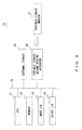
- FIG. 1 illustrates a configuration of a microscope system 100 according to this embodiment.
- FIG. 2 illustrates a hardware configuration of a computer 20 which is included in the microscope system 100. With reference to FIG. 1 and FIG. 2 , the configuration of the microscope system 100 is described.
- the microscope system 100 illustrated in FIG. 1 includes a microscope apparatus 10, a computer 20, a monitor 30, and a plurality of input apparatuses used for inputting instructions to the computer 20 (a keyboard 40, a correction collar operation apparatus 41 used for operating a correction collar 13, and a Z revolver operation apparatus 42 used for operating a Z revolver 15) .
- the monitor 30 is a touch panel display apparatus, and it operates as a display apparatus and an input apparatus.
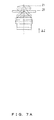
- the microscope apparatus 10 includes a transparent sample table 11 on which a sample S is arranged, a stage 12 which supports the transparent sample table 11, a correction collar 13 which is a correction apparatus which corrects a spherical aberration, an objective 14 including the correction collar 13, a Z revolver 15 on which the objective 14 is mounted, an imaging apparatus 16 which images the sample S, a correction collar driving mechanism 17 which rotates the correction collar 13, and a Z revolver driving mechanism 18 which moves the Z revolver 15 in an optical axis direction of the objective 14.
- the imaging apparatus 16 and the correction collar driving mechanism 17, and the Z revolver driving mechanism 18 are connected to the computer 20, and are configured to operate under the control of the computer 20.
- the microscope apparatus 10 In the microscope apparatus 10, light from the sample S is condensed through the transparent sample table 11 and the objective 14 on the imaging apparatus 16 so that the sample S is imaged by the imaging apparatus 16 and image data of the sample S is obtained. The obtained image data is output to the computer 20.
- the correction collar 13 is means for moving a lens in the objective 14 in an optical axis direction according to the rotation amount, and the amount of spherical aberration which is caused in the objective 14 is changed with the change in distance between lenses configuring the objective 14.
- the correction collar driving mechanism 17 rotates the correction collar 13 so that a spherical aberration in which the generation amount changes according to a thickness of the transparent sample table 11 or the depth of an observation target surface is satisfactorily corrected by the spherical aberration of the objective 14.
- the correction collar 13 is exemplified as a correction apparatus which corrects a spherical aberration; however, the correction apparatus is not limited to the correction collar 13, but may be anything that can change the amount of spherical aberration which occurs on an optical path.
- the correction apparatus may be, for example, an apparatus which moves an optical lens not illustrated which is arranged between the objective 14 and the imaging apparatus 16, or an apparatus using an LCOS (Liquid crystal on silicon (trademark)), a DFM (Deformable Mirror), a liquid lens, or the like.
- LCOS Liquid crystal on silicon
- DFM Deformable Mirror
- FIG. 1 exemplifies a configuration in which the Z revolver 15 is moved in an optical axis direction so that a respective position of the objective 14 to the sample S is changed and the observation target surface of the sample S is changed; however, a configuration in which the observation target surface is changed is not limited to this.
- the configuration may be anything that can change the relative position of the objective 14 to the sample S, and the relative position of the objective 14 to the sample S may be changed by, for example, moving the stage 12 in an optical axis direction.
- the microscope system 100 may include a stage driving mechanism which moves the stage 12 in the optical axis direction, instead of the Z revolver driving mechanism 18.
- the computer 20 is a controller which controls an operation of the entirety of the microscope system 100.
- the computer 20 may be a general-purpose computer such as a work station or a personal computer, or a dedicated apparatus.
- the computer 20 includes a CPU (Central Processing Unit) 21, a memory 22, an input I/F 23, an output I/F 24, an external storage 25, and a portable storage medium driving apparatus 26 into which a portable storage medium 27 is inserted, and these are respectively connected to a bus 28.
- FIG. 2 is an example of a configuration of the computer 20, and the computer 20 is not limited to this configuration.
- the CPU 21 executes a program and controls the entirety of the computer 20.
- the memory 22 is, for example, a RAM (Random Access Memory), and it is a memory which temporarily stores a program or data stored in the external storage 25 or the portable storage medium 27, at the time of executing the program.
- RAM Random Access Memory
- the input I/F 23 is means which detects signals from the keyboard 40, the correction collar operation apparatus 41, the Z revolver operation apparatus 42, and the monitor 30 that are input apparatuses, and it operates as an input reception unit which receives an input by an observer.
- the output I/F 24 is means which outputs signals to the monitor 30 that is a display apparatus, and it operates as a display controller which controls a display of the monitor 30.
- the output I/F 24 may output signals to a printer not illustrated.
- the external storage 25 is, for example, a hard disk storage, and it is mainly used for storing various types of data or programs.
- the portable storage medium driving apparatus 26 accommodates the portable storage medium 27, e.g., an optical disk or a CompactFlash (registered trademark), and it plays a role in assisting the external storage 25.
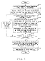
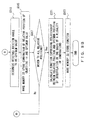
- FIG. 3 is a flowchart of a function calculation process which is performed before the observation by the microscope system according to this embodiment.
- FIG. 4 is a flowchart of a spherical aberration correction process which is performed in the observation by the microscope system according to this embodiment. With reference to FIG. 3 and FIG. 4 , the operation of the microscope system 100 is described below in detail.
- a function calculation process illustrated in FIG. 3 is performed by the computer 20 before the observation of the sample S is started.
- the process illustrated in FIG. 3 is performed by loading a program stored in the external storage 25 or the portable storage medium 27 on the memory 22 and executing it in the CPU 21, and the process is started by an instruction from an observer to start the function calculation process using, for example, the keyboard 40.
- the computer 20 controls the Z revolver driving mechanism 18 and focuses on an interface between the transparent sample table 11 and the sample S (step S101). This step can be performed with a known optional method. A relative position of the objective 14 to the sample S at this time is referred to as a position Z0.
- the computer 20 receives a plurality of inputs by the observer that specify relative positions, and stores the received relative positions in the memory 22 (step S103).
- the inputs by the observer of the relative positions are performed using an input apparatus such as the keyboard 40.
- the computer 20 displays an image of the sample S in the current relative position (in this case, the position Z0) on the monitor 30, and receives an input by the observer that specifies a range to be evaluated in the sample S (hereinafter referred as a "region of interest") (step S105).
- the input by the observer of the region of interest is performed using an input apparatus such as the keyboard 40 so as to include a portion to be observed more satisfactorily, e.g., a portion having a characteristic shape in the sample S, while observing an image 1 of the sample S, which is displayed on the monitor 30, as illustrated in FIG. 5 , for example.
- the computer 20 detects a specified portion of the image 1 of the sample S as a region of interest 2, and stores it in the memory 22.
- the computer 20 calculates an evaluation value for each rotation angle of the correction collar 13 (step S107). Specifically, the computer 20 controls the correction collar driving mechanism 17 first, and makes the correction collar driving mechanism 17 rotate the correction collar 13, as illustrated in FIG. 6A . Then, the computer 20 makes the imaging apparatus 16 obtain image data of the sample S for each rotation angle of the correction collar 13. Namely, the computer 20 makes the imaging apparatus 16 obtain plural pieces of image data while changing the rotation angle that is a set value of the correction apparatus. Furthermore, the computer 20 calculates an evaluation value indicating a contrast of each image from each of the obtained plural pieces of image data with a contrast evaluation method. When this happens, the evaluation value is calculated within the range of the region of interest 2 received from the observer in step S105. As a result, the relationship between the evaluation value and the rotation angle of the correction collar 13 as illustrated in FIG. 6B is obtained.
- the computer 20 determines a rotation angle of the correction collar 13 with a maximum evaluation value to be an optimumvalue (in this case, a rotation angle ⁇ 0) (step S109)
- a rotation angle ⁇ 0 a rotation angle ⁇ 0
- the optimum value is a set value of a correction apparatus (in this case, the rotation angle of the correction collar 13) in a state in which a spherical aberration caused according to a relative position has been corrected.
- the computer 20 makes the memory 22 store a combination of the current relative position (in this case, the position Z0) and the optimum value determined in step S109 (in this case, the rotation angle ⁇ 0) (step S111).
- step S113 the computer 20 judges whether the objective 14 has moved to all of the relative positions received in step S103 (step S113).
- the computer 20 judges that there are relative positions to which the objective 14 has not yet moved, the computer 20 controls the Z revolver driving mechanism 18 so as to move the objective 14 to the next relative position (for example, a position Z1) (step S115). Then, the processes of step S105 to step S111 are repeated.
- step S105 determines a rotation angle with the calculated evaluation value maximum to be an optimum value, for each of the relative positions, and obtains a plurality of combinations of a relative position and an optimum value.
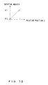
- the computer 20 judges that the objective 14 has already moved to all of the relative positions, the computer 20 reads the plurality of combinations of a relative position and an optimum value, which are stored in step S111, from the memory 22, and calculates a function expressing the relationship between the relative position and the optimum value on the basis of the plurality of combinations by interpolation (step S117).
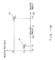
- the function may be calculated by linear interpolation on the basis of the combination of the relative position Z0 and the optimum value ⁇ 0 and the combination of the relative position Z1 and the optimum value ⁇ 1, as illustrated in FIG. 7A and FIG. 7B .
- An interpolation method is not limited to a linear interpolation method, and an optional interpolation method may be used.
- step S119 the computer 20 makes the memory 22 store the function calculated in step S117 (step S119), and finishes the process.
- the computer 20 performs a spherical aberration correction process illustrated in FIG. 4 .
- the spherical aberration correction process illustrated in FIG. 4 is performed by loading a program stored in the external storage 25 or the portable storage medium 27 on the memory 22 and executing it in the CPU 21, and it is started by an instruction from an observer to start the spherical aberration correction process using, for example, the keyboard 40.
- the computer 20 receives an input by an observer which specifies an observation target surface (step S201).
- the input by the observer of the observation target surface is performed using an input apparatus such as the keyboard 40.
- the computer 20 reads the function expressing the relationship between a relative position and an optimum value, which is calculated in the function calculation process illustrated in FIG. 3 , from the memory 22 (step S203).
- the computer 20 calculates an optimum value according to the observation target surface (i.e., a rotation angle of the correction collar 13) on the basis of the function read in step S203 and the relative position which is determined from the observation target surface received in step S201 (step S205). Specifically, the optimum value according to the observation target surface is calculated by substituting the relative position received in step S201 for the function read in step S203.
- the observation target surface i.e., a rotation angle of the correction collar 13
- step S207 the correction collar driving mechanism 17 rotates the correction collar 13 according to the optimum value calculated in step S205 (step S207), and finishes the process.
- the correction collar driving mechanism 17 rotates the correction collar 13 according to the optimum value calculated by the computer 20, and sets the rotation angle of the correction collar 13 to be the optimum value.
- the microscope system 100 calculates a function expressing the relationship between a relative position and an optimum value by interpolation using the sample S that is an observation target, and corrects a spherical aberration using the function. Accordingly, in the microscope system 100, even when the depth of an observation target surface is changed, a spherical aberration which changes according to the depth of the observation target surface can be appropriately corrected.
- the microscope system 100 can appropriately correct the spherical aberration which changes according to the depth of the observation target surface. Therefore, in the microscope system 100, the spherical aberration according to the observation target surface can be easily corrected without the observer's input of information of the sample S, such as a temperature or a refractive index of the sample S. In addition, the spherical aberration can be appropriately corrected even when the observer does not grasp the information of the sample S.
- the microscope system 100 calculates a function using the sample S that is an observation target, before the observation is started, and corrects a spherical aberration using this function. Therefore, in the microscope system 100, a large amount of data does not need to be prepared in advance for each type of the sample S or each state of the sample S, and the observation of an unknown sample S can also be handled.
- the function calculated before the start of the observation is calculated by interpolating a plurality of combinations of a relative position and an optimum value, and an optimum value according to the observation target surface is calculated by substituting a relative position determined from the observation target surface for the function. Therefore, in the microscope system 100, complicated arithmetic operations do not need to be performed in order to correct the spherical aberration, and the spherical aberration according to the observation target surface can be corrected in a short time.
- the microscope system 100 In the microscope system 100, once a function is calculated before the observation is started, the spherical aberration can be corrected every time using the function when the observation target surface changes. In the microscope system 100, a function does not need to be calculated every time the observation target surface changes, and therefore, the spherical aberration according to the observation target surface can be corrected in a short time. Accordingly, the microscope system 100 is especially suitable, for example, in a case in which a Z-stack, in which a large number of images are captured while changing the depth of the observation target surface, is performed.
- an optimum value can be calculated by only substituting a relative position for a function, and therefore, a sample does not need to be irradiated with light only for the purpose of calculating the optimum value. For that reason, the microscope system 100 is especially suitable for fluorescence observation, in which a sample fades in color due to light irradiation.
- the input of a relative position received in step S103 may be limited to only an input of a relative position where a focal position of the objective 14 is located closer to the sample S than the interface between the transparent sample table 11 and the sample S.
- the focal position of the objective 14 corresponding to the relative position is limited within the sample S, and therefore, in step S117, a function which corrects a spherical aberration more appropriately can be calculated.
- a moving distance of the objective 14 from the position Z0 which is a relative position to which the objective 14 moves in step S101, may be limited to be within the working distance (WD) of the objective 14.
- the objective 14 can avoid touching the transparent sample table 11.
- the objective 14 may be configured to move to relative positions in order of nearness to the relative position (the position Z0) to which the objective 14 moves in step S101.
- a direction in which the Z revolver driving mechanism 18 moves the objective 14 is fixed, and therefore, the high-precision positioning is available with the influence of a backlash removed.
- the correction collar driving mechanism 17 rotates the correction collar 13 in step S107 to a fixed direction, the influence of a backlash can be removed similarly.
- a stepping motor is preferably used for the correction collar driving mechanism 17.
- the correction collar driving mechanism 17 is a stepping motor, a displacement amount can be determined by counting the number of drive pulses of the stepping motor, and therefore, high-precision positioning is available without using a displacement sensor.
- FIG. 3 and FIG. 4 are an example of the processes performed in the microscope system 100 according to this embodiment, and they can be modified in various ways.
- step S101 in FIG. 3 an example of focusing on the interface between the transparent sample table 11 and the sample S is given; however, the objective 14 may be moved to a relative position specified by the observer from the beginning.
- step S105 in FIG. 3 in which a region of interest is specified, may be omitted.
- a region of interest is preferably specified in step S105.
- an evaluation value expressing the brightness of an image may be calculated instead of an evaluation value expressing a contrast of an image.
- a brightness evaluation method may be used instead of a contrast evaluation method. This is because the brightness of an image increases in a state in which a spherical aberration has been satisfactorily corrected.
- a configuration of the microscope apparatus 10 is not limited to the configuration illustrated in FIG. 1 .
- the microscope apparatus 10 is illustrated as an inverted microscope; however, the microscope apparatus 10 is not limited to an inverted microscope, and it may be an upright microscope.
- step S101 an interface between a cover glass and the sample S is focused on, instead of the interface between the transparent sample table 11 and the sample S.
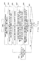
- FIGS. 8A and 8B are flowchart of a function calculation process which is performed before the observation by a microscope system according to this embodiment.
- the microscope system according to this embodiment differs from the microscope system 100 according to Embodiment 1 in that the function calculation process illustrated in FIGS. 8A and 8B is performed instead of the function calculation process illustrated in FIG. 3 .
- the microscope system according to this embodiment is the same as the microscope system 100 according to Embodiment 1, and therefore, the same components are denoted by the same references.
- the function calculation process illustrated in FIGS. 8A and 8B is performed by the computer 20.
- the process illustrated in FIGS. 8A and 8B is performed by loading a program stored in the external storage 25 or the portable storage medium 27 on the memory 22 and executing it in the CPU 21, and the process is started by the instruction from the observer to start the function calculation process using, for example, the keyboard 40.
- step S301 to step S307 are the same as those of step S101 to step S107 in FIG. 3 .
- the computer 20 calculates an evaluation value for each rotation angle of the correction collar 13. Specifically, the computer 20 controls the correction collar driving mechanism 17 first, and makes the correction collar driving mechanism 17 rotate the correction collar 13 as illustrated in FIG. 9A . Then, the computer 20 makes the imaging apparatus 16 obtain image data of the sample S for each of the rotation angles of the correction collar 13. Further, the computer 20 calculates an evaluation value expressing a contrast of each image from each piece of the obtained image data with a contrast evaluation method. When this happens, the evaluation value is calculated within a range of the region of interest 2 received from the observer in step S305. As a result, the relationship between the evaluation value and the rotation angle of the correction collar 13 is obtained as illustrated in FIG. 9B .
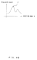
- the computer 20 makes the monitor 30 display a graph illustrating the relationship between the rotation angle of the correction collar 13 and the evaluation value as illustrated in FIG. 9B (step S309).
- the computer 20 receives an input by the observer which specifies the rotation angle (step S311).
- the input by the observer of the rotation angle is performed manually using an input apparatus such as the correction collar operation apparatus 41 while referring to the graph displayed on the monitor 30.
- the computer 20 determines the received rotation angle to be an optimum value (step S313), and makes the memory 22 store a combination of the current relative position and the optimumvalue determined in step S313 (step S315).
- the observer may specify a rotation angle corresponding to a point P by touching the point P with a maximum evaluation value on the graph illustrated in FIG. 9B .
- the computer 20 detects the touch on the monitor displaying the graph, and determines the rotation angle corresponding to the point P on the graph, which is located in the position where the touch is detected, to be an optimum value.
- step S317 the computer 20 judges whether the objective 14 moves to all of the relative positions which were received in step S303 (step S317).
- the computer 20 judges that there is a respective position to which the objective 14 has not yet moved, the computer 20 controls the Z revolver driving mechanism 18 to move the objective 14 to the next relative position (step S319). Then, the processes of step S305 to step S315 are repeated.
- the computer 20 determines the rotation angle which is received after the graph is displayed to be an optimum value, for each of the relative positions, and obtains a plurality of combinations of a relative position and an optimum value.
- the computer 20 judges that the objective 14 has already moved to all of the relative positions, the computer 20 reads the plurality of combinations of the relative position and the optimum value stored in step S315 from the memory 22, and calculates a function expressing the relationship between the relative position and the optimum value on the basis of the plurality of combinations by interpolation (step S321). Then, the computer 20 makes the memory 22 store the calculated function and finishes the process (step S323).
- the microscope system according to this embodiment a similar effect obtained in the microscope system 100 according to Embodiment 1 can be obtained. Further, similarly to the microscope system 100 according to Embodiment 1, the microscope system according to this embodiment can be modified in various ways.
- an optimum value for each of the relative positions is automatically determined, whereas, in the microscope system according to this embodiment, after a graph illustrating the relationship between a rotation angle and an evaluation value for each of the relative positions is displayed on the monitor 30, the observer determines an optimum value for each of the relative positions while referring to the graph. Therefore, an optimum value for each of the relative positions can be appropriately determined, even in a case in which a plurality of peaks of an evaluation value occur as illustrated in FIG. 9B , a case in which it is difficult to automatically specify the peak due to an influence of noise, or other cases.
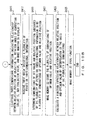
- FIGS. 10A and 10B are flowchart of a function calculation process which is performed before the observation by a microscope system according to this embodiment.
- the microscope system according to this embodiment differs from the microscope system 100 according to Embodiment 1 in that a function calculation process illustrated in FIGS. 10A and 10B is performed instead of the function calculation process illustrated in FIG. 3 .
- the microscope system according to this embodiment is similar to the microscope system 100 according to Embodiment 1, and therefore, the same components are denoted by the same references.
- the computer 20 performs the function calculation process illustrated in FIGS. 10A and 10B .
- the process illustrated in FIGS. 10A and 10B is performed by loading a program stored in the external storage 25 or the portable storage medium 27 on the memory 22 and executing it in the CPU 21, and the process is started by an instruction from the observer to start the function calculation process using, for example, the keyboard 40.
- the processes of step S401 to step S405 are similar to those of step S101 to step S105 in FIG. 3 .
- the computer 20 changes the rotation angle of the correction collar 13 and the relative position of the objective 14 in the vicinity of the relative position of the objective 14 input in step S403, i. e. , within a Z range from the relative position of the objective 14 input in step S403 to a position which is assumed to be varied by the rotation of the correction collar 13, and it calculates a plurality of evaluation values (step S407). Then, the computer 20 makes the memory 22 store a plurality of combinations of a relative position, a rotation angle, and an evaluation value (step S409).
- the computer 20 first controls the correction collar driving mechanism 17 and the Z revolver driving mechanism 18, and makes the correction collar driving mechanism 17 rotate the correction collar 13 and makes the Z revolver driving mechanism 18 move the objective 14, as illustrated in FIG. 11A . Then, the computer 20 makes the imaging apparatus 16 obtain image data of the sample S for each of the rotation angles of the correction collar 13 and for each of the relative positions of the objective 14. Namely, the computer 20 makes the imaging apparatus 16 obtain plural pieces of image data while changing the rotation angle and the relative position. Further, the computer 20 calculates an evaluation value indicating a contrast of each image from each of the obtained pieces of image data with a contrast evaluation method, and makes the memory 22 store a combination of an evaluation value, a relative position, and a rotation angle.
- step S411 the computer 20 judges whether the objective 14 has already moved to all of the relative positions received in step S403 (step S411).
- the computer 20 controls the Z revolver driving mechanism 18 so as to move the objective 14 to the next relative position (step S413). Then, the processes of step S405 to step S409 are repeated.
- step S405 by repeating the processes of step S405 to step S409 in all of the relative positions, the computer 20 obtains, for each of the input relative positions, a plurality of combinations of a relative position, a rotation angle, and an evaluation value in the vicinity of each of the input relative positions. Then, the computer 20 makes the monitor 30 display three-dimensional information indicating the relationship between an evaluation value, a relative position, and a rotation angle, which is the plurality of combinations that the computer obtained and made the memory 22 store, as illustrated in FIG. 11B , for example (step S415).
- FIG. 11B for example
- 11B illustrates contours expressing a distribution of evaluation values in a Z ⁇ plane having axes of a relative position Z and a rotation angle ⁇ , for each of the relative positions received in step S403, and illustrates the three-dimensional information indicating the relationship between the evaluation value, the relative position, and the rotation angle.
- the computer 20 receives an input by the observer which specifies a plurality of points on the illustrated three-dimensional information (step S417).
- the input by the observer of the plurality of points is performed using an input apparatus such as the monitor 30 or a keyboard 40, while referring to the three-dimensional information displayed on the monitor 30.
- the observer may specify the plurality of points by touching one point with a largest evaluation value (e.g., a point P1 or a point P2) for each of the contours on the illustrated three-dimensional information as illustrated in FIG. 11B , for example.
- a largest evaluation value e.g., a point P1 or a point P2
- the computer 20 determines a plurality of combinations of a rotation angle and a relative position, which are expressed by the plurality of points received in step S417, to be a plurality of combinations of an optimum value and a relative position (step S419), and makes the memory 22 store them (step S421).
- the computer 20 obtains the plurality of combinations of an optimum value and a relative position as described above.
- the computer 20 reads the plurality of combinations of a relative position and an optimum value stored in step S421, from the memory 22, and calculates a function expressing the relationship between a relative position and an optimum value on the basis of the plurality of combinations by interpolation (step S423). Lastly, the computer 20 makes the memory 22 store the calculated function and finishes the process (step S425).
- the microscope system according to this embodiment a similar effect in the microscope systems according to Embodiment 1 and Embodiment 2 can be obtained. Further, similarly to Embodiment 1 and Embodiment 2, the microscope system according to this embodiment can be modified in various ways.
- an optimum value for each relative position is automatically determined, whereas, in the microscope system according to this embodiment, after three-dimensional information indicating the relationship between a relative position, a rotation angle, and an evaluation value is displayed on the monitor 30, the observer determines a combination of an optimum value and a relative position which will satisfactorily correct spherical aberration while referring to the three-dimensional information. Therefore, in the microscope system according to this embodiment, similarly to the microscope system according to Embodiment 2, a combination of a relative position and an optimum value can be appropriately determined, even in a case in which a plurality of peaks of an evaluation value occur as illustrated in FIG. 9B , a case in which it is difficult to automatically specify a peak due to an influence of a noise, or other cases.
- a spherical aberration can be satisfactorily corrected even for the objective 14 in which a focal length slightly changes in accordance with the rotation angle of the correction collar 13.
Abstract
Description
- The present invention relates to a microscope system and a program of the microscope system.
- In observing a sample under a microscope, it has been known that a different amount of spherical aberration occurs depending on the thickness of a cover glass, and a correction collar of an objective has been known as means for correcting the spherical aberration caused by the thickness of the cover glass.
- In the past, the correction collar has been mainly used as the means for correcting the spherical aberration caused by the thickness of the cover glass. In recent years, a technique in which a deep portion of a sample is observed has been developed and has been popular, and the correction collar is also used for the purpose of correcting a spherical aberration which changes in accordance with the depth of an observation target surface.
- However, as it is not easy to judge whether a spherical aberration has been optimally corrected while observing a sample image, a task of correcting the spherical aberration using a correction collar tends to be avoided, and the correction collar is not often utilized sufficiently. Therefore, a technology for assisting in the task of correcting the spherical aberration using the correction collar has been proposed, and the technology is disclosed in Japanese Laid-Open Patent Application Publication No.
2005-043624 - Japanese Laid-Open Patent Application Publication No.
2005-043624 2005-043624 - However, in the microscope system disclosed in Japanese Laid-Open Patent Application Publication No.
2005-043624 - In view of the foregoing, a different technology for assisting in the task of correcting a spherical aberration using means for correcting the spherical aberration in a method different from that in the microscope system disclosed in Japanese Laid-Open Patent Application Publication No.
2005-043624 - A correction collar was given above as means for correcting a spherical aberration which changes according to a thickness of a cover glass or a depth of an observation target surface; however, a similar problem can occur in any optional means for correcting the spherical aberration.
- In view of the circumstances described above, the present invention aims at providing a technology in which an appropriate correction of a spherical aberration can be easily made in accordance with an observation target surface.
- An aspect of the present invention provides a microscope system which includes: an objective; a correction apparatus which corrects a spherical aberration; a controller which obtains a plurality of combinations of a relative position of the objective to a sample and an optimum value which is a set value of the correction apparatus in a state in which a spherical aberration caused according to the relative position has been corrected, calculates a function expressing the relationship between the relative position and the optimum value on the basis of the obtained plurality of combinations by interpolation, and calculates the optimum value according to an observation target surface on the basis of the function and the relative position which is determined from the observation target surface of the sample, which is orthogonal to an optical axis of the objective; and a correction apparatus driving apparatus which drives the correction apparatus according to the optimum value, which is calculated by the controller.
- Another aspect of the present invention provides a program of a microscope system, which includes an objective, a correction apparatus which corrects a spherical aberration, and a correction apparatus driving apparatus which drives the correction apparatus, the program causing a computer to execute the processes of: obtaining a plurality of combinations of a relative position of the objective to a sample and an optimum value which is a set value of the correction apparatus in a state in which a spherical aberration caused according to the relative position has been corrected; calculating a function which expresses the relationship between the relative position and the optimum value from the obtained plurality of combinations by interpolation; calculating the optimum value according to an observation target surface on the basis of the calculated function and the relative position which is determined from the observation target surface of the sample, which is orthogonal to an optical axis of the objective; and making the correction apparatus driving apparatus drive the correction apparatus in accordance with the calculated optimum value.
- According to the present invention, a technology in which an appropriate correction of a spherical aberration according to an observation target surface can be easily performed, can be provided.
- The present invention will be more apparent from the following detailed description when the accompanying drawings are referenced.
-
FIG. 1 illustrates a configuration of a microscope system according toEmbodiment 1 of the present invention. -
FIG. 2 illustrates a hardware configuration of acomputer 20 which is included in the microscope system according toEmbodiment 1 of the present invention. -
FIG. 3 is a flowchart of a function calculation process which is performed before the observation by the microscope system according toEmbodiment 1 of the present invention. -
FIG. 4 is a flowchart of a spherical aberration correction process which is performed in the observation by the microscope system according toEmbodiment 1 of the present invention. -
FIG. 5 is a drawing for explaining a method for specifying a region of interest. -
FIG. 6A is a drawing for explaining a method for obtaining the relationship between an evaluation value and a rotation angle of a correction collar, and illustrates the rotation of the correction collar. -
FIG. 6B is a drawing for explaining a method for obtaining the relationship between an evaluation value and a rotation angle of a correction collar, and is a graph which illustrates a evaluation value for each rotation angle. -
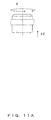
FIG. 7A is a drawing for explaining a method for obtaining a function which expresses the relationship between a relative position and a rotation angle of a correction collar, and illustrates a relative position of an objective. -
FIG. 7B is a drawing for explaining a method for obtaining a function which expresses the relationship between a relative position and a rotation angle of a correction collar, and is a graph which plots an optimum value of a correction collar for each relative position. -
FIGs. 8A and8B are flowchart of a function calculation process which is performed before the observation by a microscope system according toEmbodiment 2 of the present invention. -
FIG. 9A is another drawing for explaining the method for obtaining the relationship between an evaluation value and a rotation angle of a correction collar, and illustrates the rotation of the correction collar. -
FIG. 9B is another drawing for explaining the method for obtaining the relationship between an evaluation value and a rotation angle of a correction collar, and is a graph which illustrates an evaluation value for each rotation angle. -
FIGs. 10A and10B are flowchart of a function calculation process which is performed before the observation by a microscope system according to Embodiment 3 of the present invention. -
FIG. 11A illustrates three-dimensional information which indicates the relationship between an evaluation value, a relative position of an objective, and a rotation angle of a correction collar. -
FIG. 11B illustrates three-dimensional information which indicates the relationship between an evaluation value, a relative position of an objective, and a rotation angle of a correction collar. -
FIG. 1 illustrates a configuration of amicroscope system 100 according to this embodiment.FIG. 2 illustrates a hardware configuration of acomputer 20 which is included in themicroscope system 100. With reference toFIG. 1 andFIG. 2 , the configuration of themicroscope system 100 is described. - The
microscope system 100 illustrated inFIG. 1 includes amicroscope apparatus 10, acomputer 20, amonitor 30, and a plurality of input apparatuses used for inputting instructions to the computer 20 (akeyboard 40, a correctioncollar operation apparatus 41 used for operating acorrection collar 13, and a Zrevolver operation apparatus 42 used for operating a Z revolver 15) . Themonitor 30 is a touch panel display apparatus, and it operates as a display apparatus and an input apparatus. - The
microscope apparatus 10 includes a transparent sample table 11 on which a sample S is arranged, astage 12 which supports the transparent sample table 11, acorrection collar 13 which is a correction apparatus which corrects a spherical aberration, an objective 14 including thecorrection collar 13, aZ revolver 15 on which theobjective 14 is mounted, animaging apparatus 16 which images the sample S, a correctioncollar driving mechanism 17 which rotates thecorrection collar 13, and a Zrevolver driving mechanism 18 which moves theZ revolver 15 in an optical axis direction of theobjective 14. Theimaging apparatus 16 and the correctioncollar driving mechanism 17, and the Zrevolver driving mechanism 18 are connected to thecomputer 20, and are configured to operate under the control of thecomputer 20. - In the
microscope apparatus 10, light from the sample S is condensed through the transparent sample table 11 and the objective 14 on theimaging apparatus 16 so that the sample S is imaged by theimaging apparatus 16 and image data of the sample S is obtained. The obtained image data is output to thecomputer 20. - The
correction collar 13 is means for moving a lens in theobjective 14 in an optical axis direction according to the rotation amount, and the amount of spherical aberration which is caused in theobjective 14 is changed with the change in distance between lenses configuring theobjective 14. In themicroscope apparatus 10, the correctioncollar driving mechanism 17 rotates thecorrection collar 13 so that a spherical aberration in which the generation amount changes according to a thickness of the transparent sample table 11 or the depth of an observation target surface is satisfactorily corrected by the spherical aberration of theobjective 14. - In
FIG. 1 , thecorrection collar 13 is exemplified as a correction apparatus which corrects a spherical aberration; however, the correction apparatus is not limited to thecorrection collar 13, but may be anything that can change the amount of spherical aberration which occurs on an optical path. The correction apparatus may be, for example, an apparatus which moves an optical lens not illustrated which is arranged between the objective 14 and theimaging apparatus 16, or an apparatus using an LCOS (Liquid crystal on silicon (trademark)), a DFM (Deformable Mirror), a liquid lens, or the like. - Further,
FIG. 1 exemplifies a configuration in which theZ revolver 15 is moved in an optical axis direction so that a respective position of theobjective 14 to the sample S is changed and the observation target surface of the sample S is changed; however, a configuration in which the observation target surface is changed is not limited to this. The configuration may be anything that can change the relative position of theobjective 14 to the sample S, and the relative position of theobjective 14 to the sample S may be changed by, for example, moving thestage 12 in an optical axis direction. In this case, themicroscope system 100 may include a stage driving mechanism which moves thestage 12 in the optical axis direction, instead of the Zrevolver driving mechanism 18. - The
computer 20 is a controller which controls an operation of the entirety of themicroscope system 100. Thecomputer 20 may be a general-purpose computer such as a work station or a personal computer, or a dedicated apparatus. - As illustrated in
FIG. 2 , thecomputer 20 includes a CPU (Central Processing Unit) 21, amemory 22, an input I/F 23, an output I/F 24, anexternal storage 25, and a portable storagemedium driving apparatus 26 into which aportable storage medium 27 is inserted, and these are respectively connected to abus 28.FIG. 2 is an example of a configuration of thecomputer 20, and thecomputer 20 is not limited to this configuration. - The
CPU 21 executes a program and controls the entirety of thecomputer 20. Thememory 22 is, for example, a RAM (Random Access Memory), and it is a memory which temporarily stores a program or data stored in theexternal storage 25 or theportable storage medium 27, at the time of executing the program. - The input I/F 23 is means which detects signals from the
keyboard 40, the correctioncollar operation apparatus 41, the Zrevolver operation apparatus 42, and themonitor 30 that are input apparatuses, and it operates as an input reception unit which receives an input by an observer. The output I/F 24 is means which outputs signals to themonitor 30 that is a display apparatus, and it operates as a display controller which controls a display of themonitor 30. The output I/F 24 may output signals to a printer not illustrated. - The
external storage 25 is, for example, a hard disk storage, and it is mainly used for storing various types of data or programs. The portable storagemedium driving apparatus 26 accommodates theportable storage medium 27, e.g., an optical disk or a CompactFlash (registered trademark), and it plays a role in assisting theexternal storage 25. -
FIG. 3 is a flowchart of a function calculation process which is performed before the observation by the microscope system according to this embodiment.FIG. 4 is a flowchart of a spherical aberration correction process which is performed in the observation by the microscope system according to this embodiment. With reference toFIG. 3 andFIG. 4 , the operation of themicroscope system 100 is described below in detail. - In the
microscope system 100, after the sample S is arranged on the transparent sample table 11, a function calculation process illustrated inFIG. 3 is performed by thecomputer 20 before the observation of the sample S is started. The process illustrated inFIG. 3 is performed by loading a program stored in theexternal storage 25 or theportable storage medium 27 on thememory 22 and executing it in theCPU 21, and the process is started by an instruction from an observer to start the function calculation process using, for example, thekeyboard 40. - First, the
computer 20 controls the Zrevolver driving mechanism 18 and focuses on an interface between the transparent sample table 11 and the sample S (step S101). This step can be performed with a known optional method. A relative position of the objective 14 to the sample S at this time is referred to as a position Z0. - Then, the
computer 20 receives a plurality of inputs by the observer that specify relative positions, and stores the received relative positions in the memory 22 (step S103). The inputs by the observer of the relative positions are performed using an input apparatus such as thekeyboard 40. - Next, the
computer 20 displays an image of the sample S in the current relative position (in this case, the position Z0) on themonitor 30, and receives an input by the observer that specifies a range to be evaluated in the sample S (hereinafter referred as a "region of interest") (step S105). The input by the observer of the region of interest is performed using an input apparatus such as thekeyboard 40 so as to include a portion to be observed more satisfactorily, e.g., a portion having a characteristic shape in the sample S, while observing animage 1 of the sample S, which is displayed on themonitor 30, as illustrated inFIG. 5 , for example. Thecomputer 20 detects a specified portion of theimage 1 of the sample S as a region ofinterest 2, and stores it in thememory 22. - Further, the
computer 20 calculates an evaluation value for each rotation angle of the correction collar 13 (step S107). Specifically, thecomputer 20 controls the correctioncollar driving mechanism 17 first, and makes the correctioncollar driving mechanism 17 rotate thecorrection collar 13, as illustrated inFIG. 6A . Then, thecomputer 20 makes theimaging apparatus 16 obtain image data of the sample S for each rotation angle of thecorrection collar 13. Namely, thecomputer 20 makes theimaging apparatus 16 obtain plural pieces of image data while changing the rotation angle that is a set value of the correction apparatus. Furthermore, thecomputer 20 calculates an evaluation value indicating a contrast of each image from each of the obtained plural pieces of image data with a contrast evaluation method. When this happens, the evaluation value is calculated within the range of the region ofinterest 2 received from the observer in step S105. As a result, the relationship between the evaluation value and the rotation angle of thecorrection collar 13 as illustrated inFIG. 6B is obtained. - When the evaluation value for each of the rotation angles is calculated, the
computer 20 determines a rotation angle of thecorrection collar 13 with a maximum evaluation value to be an optimumvalue (in this case, a rotation angle θ0) (step S109) The reason for this is that the contrast of an image is high in a state in which a spherical aberration has been satisfactorily corrected and therefore a state in which an evaluation value is at the maximum is considered to be a state in which the spherical aberration has been satisfactorily corrected. Note that the optimum value is a set value of a correction apparatus (in this case, the rotation angle of the correction collar 13) in a state in which a spherical aberration caused according to a relative position has been corrected. - When the optimum value is calculated, the
computer 20 makes thememory 22 store a combination of the current relative position (in this case, the position Z0) and the optimum value determined in step S109 (in this case, the rotation angle θ0) (step S111). - Then, the
computer 20 judges whether the objective 14 has moved to all of the relative positions received in step S103 (step S113). When thecomputer 20 judges that there are relative positions to which the objective 14 has not yet moved, thecomputer 20 controls the Zrevolver driving mechanism 18 so as to move the objective 14 to the next relative position (for example, a position Z1) (step S115). Then, the processes of step S105 to step S111 are repeated. - As described above, by repeating the processes of step S105 to step S111 in all of the relative positions, the
computer 20 determines a rotation angle with the calculated evaluation value maximum to be an optimum value, for each of the relative positions, and obtains a plurality of combinations of a relative position and an optimum value. - When the
computer 20 judges that the objective 14 has already moved to all of the relative positions, thecomputer 20 reads the plurality of combinations of a relative position and an optimum value, which are stored in step S111, from thememory 22, and calculates a function expressing the relationship between the relative position and the optimum value on the basis of the plurality of combinations by interpolation (step S117). The function may be calculated by linear interpolation on the basis of the combination of the relative position Z0 and the optimum value θ0 and the combination of the relative position Z1 and the optimum value θ1, as illustrated inFIG. 7A andFIG. 7B . An interpolation method is not limited to a linear interpolation method, and an optional interpolation method may be used. - Lastly, the
computer 20 makes thememory 22 store the function calculated in step S117 (step S119), and finishes the process. - In the
microscope system 100, when the function calculation process illustrated inFIG. 3 is finished and the sample S is observed, thecomputer 20 performs a spherical aberration correction process illustrated inFIG. 4 . The spherical aberration correction process illustrated inFIG. 4 is performed by loading a program stored in theexternal storage 25 or theportable storage medium 27 on thememory 22 and executing it in theCPU 21, and it is started by an instruction from an observer to start the spherical aberration correction process using, for example, thekeyboard 40. - First, the
computer 20 receives an input by an observer which specifies an observation target surface (step S201). The input by the observer of the observation target surface is performed using an input apparatus such as thekeyboard 40. - Next, the
computer 20 reads the function expressing the relationship between a relative position and an optimum value, which is calculated in the function calculation process illustrated inFIG. 3 , from the memory 22 (step S203). - Then, the
computer 20 calculates an optimum value according to the observation target surface (i.e., a rotation angle of the correction collar 13) on the basis of the function read in step S203 and the relative position which is determined from the observation target surface received in step S201 (step S205). Specifically, the optimum value according to the observation target surface is calculated by substituting the relative position received in step S201 for the function read in step S203. - Lastly, the
computer 20 makes the correctioncollar driving mechanism 17 rotate thecorrection collar 13 according to the optimum value calculated in step S205 (step S207), and finishes the process. As a result, the correctioncollar driving mechanism 17 rotates thecorrection collar 13 according to the optimum value calculated by thecomputer 20, and sets the rotation angle of thecorrection collar 13 to be the optimum value. - The
microscope system 100 according to this embodiment calculates a function expressing the relationship between a relative position and an optimum value by interpolation using the sample S that is an observation target, and corrects a spherical aberration using the function. Accordingly, in themicroscope system 100, even when the depth of an observation target surface is changed, a spherical aberration which changes according to the depth of the observation target surface can be appropriately corrected. - Further, when the observer merely performs a plurality of inputs which specify a plurality of relative position, a region of interest, and an observation target surface, the
microscope system 100 can appropriately correct the spherical aberration which changes according to the depth of the observation target surface. Therefore, in themicroscope system 100, the spherical aberration according to the observation target surface can be easily corrected without the observer's input of information of the sample S, such as a temperature or a refractive index of the sample S. In addition, the spherical aberration can be appropriately corrected even when the observer does not grasp the information of the sample S. - Further, the
microscope system 100 calculates a function using the sample S that is an observation target, before the observation is started, and corrects a spherical aberration using this function. Therefore, in themicroscope system 100, a large amount of data does not need to be prepared in advance for each type of the sample S or each state of the sample S, and the observation of an unknown sample S can also be handled. - Further, in the
microscope system 100, the function calculated before the start of the observation is calculated by interpolating a plurality of combinations of a relative position and an optimum value, and an optimum value according to the observation target surface is calculated by substituting a relative position determined from the observation target surface for the function. Therefore, in themicroscope system 100, complicated arithmetic operations do not need to be performed in order to correct the spherical aberration, and the spherical aberration according to the observation target surface can be corrected in a short time. - In the
microscope system 100, once a function is calculated before the observation is started, the spherical aberration can be corrected every time using the function when the observation target surface changes. In themicroscope system 100, a function does not need to be calculated every time the observation target surface changes, and therefore, the spherical aberration according to the observation target surface can be corrected in a short time. Accordingly, themicroscope system 100 is especially suitable, for example, in a case in which a Z-stack, in which a large number of images are captured while changing the depth of the observation target surface, is performed. Further, an optimum value can be calculated by only substituting a relative position for a function, and therefore, a sample does not need to be irradiated with light only for the purpose of calculating the optimum value. For that reason, themicroscope system 100 is especially suitable for fluorescence observation, in which a sample fades in color due to light irradiation. - In the
microscope system 100, the input of a relative position received in step S103 may be limited to only an input of a relative position where a focal position of the objective 14 is located closer to the sample S than the interface between the transparent sample table 11 and the sample S. By limiting the input of the relative position as described above, the focal position of the objective 14 corresponding to the relative position is limited within the sample S, and therefore, in step S117, a function which corrects a spherical aberration more appropriately can be calculated. - In the
microscope system 100, a moving distance of the objective 14 from the position Z0, which is a relative position to which the objective 14 moves in step S101, may be limited to be within the working distance (WD) of the objective 14. As a result, the objective 14 can avoid touching the transparent sample table 11. - In the
microscope system 100, in step S115, the objective 14 may be configured to move to relative positions in order of nearness to the relative position (the position Z0) to which the objective 14 moves in step S101. By determining the order of relative positions to which the objective 14 moves as described above, a direction in which the Zrevolver driving mechanism 18 moves the objective 14 is fixed, and therefore, the high-precision positioning is available with the influence of a backlash removed. By also limiting a direction in which the correctioncollar driving mechanism 17 rotates thecorrection collar 13 in step S107 to a fixed direction, the influence of a backlash can be removed similarly. In a case in which the moving direction or the rotation direction is limited to a fixed direction, a stepping motor is preferably used for the correctioncollar driving mechanism 17. When the correctioncollar driving mechanism 17 is a stepping motor, a displacement amount can be determined by counting the number of drive pulses of the stepping motor, and therefore, high-precision positioning is available without using a displacement sensor. - The processes illustrated in
FIG. 3 andFIG. 4 are an example of the processes performed in themicroscope system 100 according to this embodiment, and they can be modified in various ways. For example, in step S101 inFIG. 3 , an example of focusing on the interface between the transparent sample table 11 and the sample S is given; however, the objective 14 may be moved to a relative position specified by the observer from the beginning. - Further, step S105 in
FIG. 3 , in which a region of interest is specified, may be omitted. However, in a case in which a plurality of peaks of an evaluation value occur in step S107 when the entirety of the sample S is evaluated, a region of interest is preferably specified in step S105. By appropriately specifying the region ofinterest 2, a situation in which a plurality of peaks of an evaluation value occur can be avoided, and therefore, thecomputer 20 can determine an optimum value at a higher speed. - In step S107 in
FIG. 3 , an evaluation value expressing the brightness of an image may be calculated instead of an evaluation value expressing a contrast of an image. In this case, a brightness evaluation method may be used instead of a contrast evaluation method. This is because the brightness of an image increases in a state in which a spherical aberration has been satisfactorily corrected. - A configuration of the
microscope apparatus 10 is not limited to the configuration illustrated inFIG. 1 . For example, inFIG. 1 , themicroscope apparatus 10 is illustrated as an inverted microscope; however, themicroscope apparatus 10 is not limited to an inverted microscope, and it may be an upright microscope. In this case, in step S101, an interface between a cover glass and the sample S is focused on, instead of the interface between the transparent sample table 11 and the sample S. -
FIGS. 8A and8B are flowchart of a function calculation process which is performed before the observation by a microscope system according to this embodiment. With reference toFIGS. 8A and8B , the operation of the microscope system according to this embodiment is described below in detail. The microscope system according to this embodiment differs from themicroscope system 100 according toEmbodiment 1 in that the function calculation process illustrated inFIGS. 8A and8B is performed instead of the function calculation process illustrated inFIG. 3 . In the other respects, the microscope system according to this embodiment is the same as themicroscope system 100 according toEmbodiment 1, and therefore, the same components are denoted by the same references. - In the microscope system according to this embodiment, after the sample S is arranged on the transparent sample table 11 and before the observation of the sample S is started, the function calculation process illustrated in
FIGS. 8A and8B is performed by thecomputer 20. The process illustrated inFIGS. 8A and8B is performed by loading a program stored in theexternal storage 25 or theportable storage medium 27 on thememory 22 and executing it in theCPU 21, and the process is started by the instruction from the observer to start the function calculation process using, for example, thekeyboard 40. - The processes of step S301 to step S307 are the same as those of step S101 to step S107 in
FIG. 3 . In step S307, thecomputer 20 calculates an evaluation value for each rotation angle of thecorrection collar 13. Specifically, thecomputer 20 controls the correctioncollar driving mechanism 17 first, and makes the correctioncollar driving mechanism 17 rotate thecorrection collar 13 as illustrated inFIG. 9A . Then, thecomputer 20 makes theimaging apparatus 16 obtain image data of the sample S for each of the rotation angles of thecorrection collar 13. Further, thecomputer 20 calculates an evaluation value expressing a contrast of each image from each piece of the obtained image data with a contrast evaluation method. When this happens, the evaluation value is calculated within a range of the region ofinterest 2 received from the observer in step S305. As a result, the relationship between the evaluation value and the rotation angle of thecorrection collar 13 is obtained as illustrated inFIG. 9B . - When the evaluation value is calculated for each of the rotation angles, the
computer 20 makes themonitor 30 display a graph illustrating the relationship between the rotation angle of thecorrection collar 13 and the evaluation value as illustrated inFIG. 9B (step S309). - Then, the
computer 20 receives an input by the observer which specifies the rotation angle (step S311). The input by the observer of the rotation angle is performed manually using an input apparatus such as the correctioncollar operation apparatus 41 while referring to the graph displayed on themonitor 30. Thecomputer 20 determines the received rotation angle to be an optimum value (step S313), and makes thememory 22 store a combination of the current relative position and the optimumvalue determined in step S313 (step S315). The observer may specify a rotation angle corresponding to a point P by touching the point P with a maximum evaluation value on the graph illustrated inFIG. 9B . In this case, thecomputer 20 detects the touch on the monitor displaying the graph, and determines the rotation angle corresponding to the point P on the graph, which is located in the position where the touch is detected, to be an optimum value. - Then, the
computer 20 judges whether the objective 14 moves to all of the relative positions which were received in step S303 (step S317). When thecomputer 20 judges that there is a respective position to which the objective 14 has not yet moved, thecomputer 20 controls the Zrevolver driving mechanism 18 to move the objective 14 to the next relative position (step S319). Then, the processes of step S305 to step S315 are repeated. - As described above, by repeating the processes of step S305 to step S315 in all of the relative positions, the
computer 20 determines the rotation angle which is received after the graph is displayed to be an optimum value, for each of the relative positions, and obtains a plurality of combinations of a relative position and an optimum value. - When the
computer 20 judges that the objective 14 has already moved to all of the relative positions, thecomputer 20 reads the plurality of combinations of the relative position and the optimum value stored in step S315 from thememory 22, and calculates a function expressing the relationship between the relative position and the optimum value on the basis of the plurality of combinations by interpolation (step S321). Then, thecomputer 20 makes thememory 22 store the calculated function and finishes the process (step S323). - Also in the microscope system according to this embodiment, a similar effect obtained in the
microscope system 100 according toEmbodiment 1 can be obtained. Further, similarly to themicroscope system 100 according toEmbodiment 1, the microscope system according to this embodiment can be modified in various ways. - In the
microscope system 100 according toEmbodiment 1, an optimum value for each of the relative positions is automatically determined, whereas, in the microscope system according to this embodiment, after a graph illustrating the relationship between a rotation angle and an evaluation value for each of the relative positions is displayed on themonitor 30, the observer determines an optimum value for each of the relative positions while referring to the graph. Therefore, an optimum value for each of the relative positions can be appropriately determined, even in a case in which a plurality of peaks of an evaluation value occur as illustrated inFIG. 9B , a case in which it is difficult to automatically specify the peak due to an influence of noise, or other cases. -
FIGS. 10A and10B are flowchart of a function calculation process which is performed before the observation by a microscope system according to this embodiment. With reference toFIGS. 10A and10B , the operation of the microscope system according to this embodiment is described below in detail. The microscope system according to this embodiment differs from themicroscope system 100 according toEmbodiment 1 in that a function calculation process illustrated inFIGS. 10A and10B is performed instead of the function calculation process illustrated inFIG. 3 . In the other respects, the microscope system according to this embodiment is similar to themicroscope system 100 according toEmbodiment 1, and therefore, the same components are denoted by the same references. - In the microscope system according to this embodiment, after the sample S is arranged on the transparent sample table 11 and before the observation of the sample S is started, the
computer 20 performs the function calculation process illustrated inFIGS. 10A and10B . The process illustrated inFIGS. 10A and10B is performed by loading a program stored in theexternal storage 25 or theportable storage medium 27 on thememory 22 and executing it in theCPU 21, and the process is started by an instruction from the observer to start the function calculation process using, for example, thekeyboard 40. The processes of step S401 to step S405 are similar to those of step S101 to step S105 inFIG. 3 . - The
computer 20 changes the rotation angle of thecorrection collar 13 and the relative position of the objective 14 in the vicinity of the relative position of the objective 14 input in step S403, i. e. , within a Z range from the relative position of the objective 14 input in step S403 to a position which is assumed to be varied by the rotation of thecorrection collar 13, and it calculates a plurality of evaluation values (step S407). Then, thecomputer 20 makes thememory 22 store a plurality of combinations of a relative position, a rotation angle, and an evaluation value (step S409). - Specifically, the
computer 20 first controls the correctioncollar driving mechanism 17 and the Zrevolver driving mechanism 18, and makes the correctioncollar driving mechanism 17 rotate thecorrection collar 13 and makes the Zrevolver driving mechanism 18 move the objective 14, as illustrated inFIG. 11A . Then, thecomputer 20 makes theimaging apparatus 16 obtain image data of the sample S for each of the rotation angles of thecorrection collar 13 and for each of the relative positions of the objective 14. Namely, thecomputer 20 makes theimaging apparatus 16 obtain plural pieces of image data while changing the rotation angle and the relative position. Further, thecomputer 20 calculates an evaluation value indicating a contrast of each image from each of the obtained pieces of image data with a contrast evaluation method, and makes thememory 22 store a combination of an evaluation value, a relative position, and a rotation angle. - Then, the
computer 20 judges whether the objective 14 has already moved to all of the relative positions received in step S403 (step S411). When the computer judges that there is a relative position to which the objective 14 has not yet moved, thecomputer 20 controls the Zrevolver driving mechanism 18 so as to move the objective 14 to the next relative position (step S413). Then, the processes of step S405 to step S409 are repeated. - As described above, by repeating the processes of step S405 to step S409 in all of the relative positions, the
computer 20 obtains, for each of the input relative positions, a plurality of combinations of a relative position, a rotation angle, and an evaluation value in the vicinity of each of the input relative positions. Then, thecomputer 20 makes themonitor 30 display three-dimensional information indicating the relationship between an evaluation value, a relative position, and a rotation angle, which is the plurality of combinations that the computer obtained and made thememory 22 store, as illustrated inFIG. 11B , for example (step S415).FIG. 11B illustrates contours expressing a distribution of evaluation values in a Zθ plane having axes of a relative position Z and a rotation angle θ, for each of the relative positions received in step S403, and illustrates the three-dimensional information indicating the relationship between the evaluation value, the relative position, and the rotation angle. - Then, the
computer 20 receives an input by the observer which specifies a plurality of points on the illustrated three-dimensional information (step S417). The input by the observer of the plurality of points is performed using an input apparatus such as themonitor 30 or akeyboard 40, while referring to the three-dimensional information displayed on themonitor 30. The observer may specify the plurality of points by touching one point with a largest evaluation value (e.g., a point P1 or a point P2) for each of the contours on the illustrated three-dimensional information as illustrated inFIG. 11B , for example. - The
computer 20 determines a plurality of combinations of a rotation angle and a relative position, which are expressed by the plurality of points received in step S417, to be a plurality of combinations of an optimum value and a relative position (step S419), and makes thememory 22 store them (step S421). In this embodiment, thecomputer 20 obtains the plurality of combinations of an optimum value and a relative position as described above. - Then, the
computer 20 reads the plurality of combinations of a relative position and an optimum value stored in step S421, from thememory 22, and calculates a function expressing the relationship between a relative position and an optimum value on the basis of the plurality of combinations by interpolation (step S423). Lastly, thecomputer 20 makes thememory 22 store the calculated function and finishes the process (step S425). - In the microscope system according to this embodiment, a similar effect in the microscope systems according to
Embodiment 1 andEmbodiment 2 can be obtained. Further, similarly toEmbodiment 1 andEmbodiment 2, the microscope system according to this embodiment can be modified in various ways. - In the
microscope system 100 according toEmbodiment 1, an optimum value for each relative position is automatically determined, whereas, in the microscope system according to this embodiment, after three-dimensional information indicating the relationship between a relative position, a rotation angle, and an evaluation value is displayed on themonitor 30, the observer determines a combination of an optimum value and a relative position which will satisfactorily correct spherical aberration while referring to the three-dimensional information. Therefore, in the microscope system according to this embodiment, similarly to the microscope system according toEmbodiment 2, a combination of a relative position and an optimum value can be appropriately determined, even in a case in which a plurality of peaks of an evaluation value occur as illustrated inFIG. 9B , a case in which it is difficult to automatically specify a peak due to an influence of a noise, or other cases. - Generally, when the focal length of the objective 14 changes in accordance with the rotation angle of the
correction collar 13, it cannot be judged whether the variation in evaluation value is caused by the correction of an aberration or the movement of a focal position. However, it can be at least considered that the aberration has been satisfactorily corrected in a combination of a relative position and a rotation angle with a largest evaluation value in the three-dimensional information described above, which is illustrated using contours, etc. - Accordingly, in the microscope system according to this embodiment, in which a function expressing the relationship between a relative position and an optimum value is calculated using the combination of the relative position and the rotation angle with a largest evaluation value in the three-dimensional information, a spherical aberration can be satisfactorily corrected even for the objective 14 in which a focal length slightly changes in accordance with the rotation angle of the
correction collar 13. - Each of the embodiments described above is given as a concrete example in order to facilitate the understanding of the invention, and the present invention is not limited to these embodiments. The microscope system according to each of the embodiments should be modified and varied in various ways within the scope of the present invention specified in the claims.
Claims (9)
- A microscope system (100), comprising:an objective (14);a correction apparatus (13) configured to correct a spherical aberration;a controller (20) configured to obtain a plurality of combinations of a relative position of the objective (14) to a sample (S) and an optimum value, which is a set value of the correction apparatus (13) in a state in which a spherical aberration caused in accordance with the relative position has been corrected, configured to calculate a function expressing a relationship between the relative position and the optimum value on the basis of the obtained plurality of combinations by interpolation, and configured to calculate the optimum value according to an observation target surface of the sample (S), which is orthogonal to an optical axis of the objective (14), on the basis of the function and the relative position which is determined from the observation target surface; anda correction apparatus driving apparatus (17) configured to drive the correction apparatus (13) in accordance with the optimum value, which is calculated by the controller (20).
- The microscope system (100) according to claim 1, wherein
the correction apparatus (13) is a correction collar which moves a lens in the objective (14). - The microscope system (100) according to claim 2, wherein
the controller (20) receives a plurality of inputs by an observer which each specify the relative position, determines the set value with a maximum evaluation value among a plurality of evaluation values, each of which is calculated with a contrast evaluation method or a brightness evaluation method from each of obtained plural pieces of image data of the sample while changing the set value for each of the received relative positions, to be the optimum value, and obtains the plurality of combinations of the relative position and the optimum value. - The microscope system (100) according to claim 2, wherein
the controller (20) receives a plurality of inputs by an observer which each specify the relative position, makes a display apparatus (30) display a graph indicating a relationship between an evaluation value, which is calculated with a contrast evaluation method or a brightness evaluation method from each of obtained plural pieces of image data of the sample (S) while changing the set value for each of the received relative positions, and the set value, receives an input by the observer which specifies the set value for each of the received relative positions, determines the received set value to be the optimum value, and obtains the plurality of combinations of the relative position and the optimum value. - The microscope system (100) according to claim 4, wherein
the controller (20) detects a contact to the display apparatus (30), which displays the graph, and determines the set value corresponding to a point on the graph which is located in a position in which the contact is detected to be the optimum value. - The microscope system (100) according to claim 2, wherein
the controller (20) illustrates three-dimensional information indicating a relationship between an evaluation value, which is calculated with the contrast evaluation method or the brightness evaluation method from each of obtained plural pieces of image data of the sample while changing the relative position and the set value of the correction apparatus (13), the relative position, and the set value, and makes the display apparatus (30) display the three-dimensional information, receives an input by the observer which specifies a plurality of points on the three-dimensional information, and obtains a combination of the set value and the relative position which is indicated by each of the received plurality of points as each of the plurality of combinations. - The microscope system (100) according to any one of claims 3 to 6, wherein
the controller (20) receives an input by the observer which specifies a range to be evaluated in the sample (S), and calculates the evaluation value in the received range. - The microscope system (100) according to any one of claims 1 to 7, wherein
the controller (20) receives an input by the observer which specifies the observation target surface, and calculates the optimum value according to the observation target surface on the basis of the function and the relative position, which is determined from the received observation target surface. - A program of a microscope system (100), the microscope system comprising an objective (14), a correction apparatus (13) configured to correct a spherical aberration, and a correction apparatus driving apparatus (17) configured to drive the correction apparatus (13), wherein the program causes a computer (20) to execute processes of:obtaining a plurality of combinations of a relative position of the objective (14) to a sample (S) and an optimum value, which is a set value of the correction apparatus (13) in a state in which a spherical aberration caused in accordance with the relative position has been corrected;calculating a function which indicates a relationship between the relative position and the optimum value from the obtained plurality of combinations by interpolation;calculating the optimum value according to an observation target surface of the sample (S), which is orthogonal to an optical axis of the objective (14), on the basis of the calculated function and the relative position which is determined from the observation target surface; andmaking the correction apparatus driving apparatus (17) drive the correction apparatus (13) in accordance with the calculated optimum value.
Applications Claiming Priority (1)
| Application Number | Priority Date | Filing Date | Title |
|---|---|---|---|
| JP2013031483A JP6180130B2 (en) | 2013-02-20 | 2013-02-20 | Microscope system, program, and method for correcting spherical aberration |
Publications (3)
| Publication Number | Publication Date |
|---|---|
| EP2770360A2 true EP2770360A2 (en) | 2014-08-27 |
| EP2770360A3 EP2770360A3 (en) | 2018-01-03 |
| EP2770360B1 EP2770360B1 (en) | 2022-01-12 |
Family
ID=50071532
Family Applications (1)
| Application Number | Title | Priority Date | Filing Date |
|---|---|---|---|
| EP14154835.4A Active EP2770360B1 (en) | 2013-02-20 | 2014-02-12 | Microscope system and program |
Country Status (3)
| Country | Link |
|---|---|
| US (1) | US9411142B2 (en) |
| EP (1) | EP2770360B1 (en) |
| JP (1) | JP6180130B2 (en) |
Cited By (4)
| Publication number | Priority date | Publication date | Assignee | Title |
|---|---|---|---|---|
| EP3035104A3 (en) * | 2014-12-15 | 2016-07-20 | Olympus Corporation | Microscope system and setting value calculation method |
| US10288877B2 (en) | 2015-07-16 | 2019-05-14 | Olympus Corporation | Microscopy system, determination method, and recording medium |
| US11215808B2 (en) | 2017-01-05 | 2022-01-04 | Olympus Corporation | Microscope parameter setting method and observation method recognizing the shape of a cell |
| WO2022269442A1 (en) * | 2021-06-24 | 2022-12-29 | Fei Deutschland Gmbh | Systems and methods for motorized adjustment of objective lens correction collar |
Families Citing this family (17)
| Publication number | Priority date | Publication date | Assignee | Title |
|---|---|---|---|---|
| JP6196825B2 (en) * | 2013-07-09 | 2017-09-13 | オリンパス株式会社 | Microscope system and method for measuring refractive index of sample |
| JP6422761B2 (en) * | 2014-12-15 | 2018-11-14 | オリンパス株式会社 | Microscope system and method for calculating relationship between Z position and set value of correction device |
| JP6434296B2 (en) * | 2014-12-15 | 2018-12-05 | オリンパス株式会社 | Microscope system, set value calculation method, and program |
| JP6423261B2 (en) * | 2014-12-15 | 2018-11-14 | オリンパス株式会社 | Microscope system, function calculation method, and program |
| JP6562547B2 (en) * | 2015-07-16 | 2019-08-21 | オリンパス株式会社 | Microscope system, calculation method, and program |
| JP6552041B2 (en) * | 2015-07-16 | 2019-07-31 | オリンパス株式会社 | Microscope system, refractive index calculation method, and program |
| JP2018017970A (en) | 2016-07-29 | 2018-02-01 | オリンパス株式会社 | Optical sheet microscope and method for controlling optical sheet microscope |
| WO2018087820A1 (en) * | 2016-11-08 | 2018-05-17 | 株式会社ニコン | Image group generating device, spherical aberration correcting device, microscope, program, and method for correcting spherical aberration |
| DE102017105928A1 (en) | 2017-03-20 | 2018-09-20 | Carl Zeiss Microscopy Gmbh | Microscope and method for imaging an object |
| DE102017105926A1 (en) | 2017-03-20 | 2018-09-20 | Carl Zeiss Microscopy Gmbh | Method and microscope for imaging an object |
| JP6969134B2 (en) * | 2017-03-31 | 2021-11-24 | 株式会社ニコン | Correction amount calculation device, microscope, correction amount calculation program, correction amount calculation method |
| JP6887875B2 (en) * | 2017-05-22 | 2021-06-16 | オリンパス株式会社 | Microscope system, control method, and program |
| JP6957204B2 (en) * | 2017-05-30 | 2021-11-02 | オリンパス株式会社 | Microscope system, control method, and program |
| JP2018205373A (en) * | 2017-05-31 | 2018-12-27 | オリンパス株式会社 | microscope |
| JP7041550B2 (en) * | 2018-02-26 | 2022-03-24 | オリンパス株式会社 | Microscope system |
| DE102018126007B4 (en) | 2018-10-19 | 2024-02-01 | Leica Microsystems Cms Gmbh | Method for correcting a spherical aberration of a microscope and microscope |
| EP3816611B1 (en) | 2019-10-29 | 2023-01-25 | Leica Microsystems CMS GmbH | Microscope and method for determining an aberration in a microscope |
Citations (1)
| Publication number | Priority date | Publication date | Assignee | Title |
|---|---|---|---|---|
| JP2005043624A (en) | 2003-07-28 | 2005-02-17 | Nikon Corp | Microscope control unit, microscope system, and microscope objective lens |
Family Cites Families (8)
| Publication number | Priority date | Publication date | Assignee | Title |
|---|---|---|---|---|
| JP4912545B2 (en) * | 2001-07-13 | 2012-04-11 | オリンパス株式会社 | Confocal laser scanning microscope |
| JP4554174B2 (en) | 2003-07-09 | 2010-09-29 | オリンパス株式会社 | Microscope system, microscope control method, and program |
| GB0407566D0 (en) * | 2004-04-02 | 2004-05-05 | Isis Innovation | Method for the adjustment of spherical aberration |
| JP4766591B2 (en) * | 2005-03-09 | 2011-09-07 | 大学共同利用機関法人情報・システム研究機構 | microscope |
| JP2008276070A (en) * | 2007-05-02 | 2008-11-13 | Olympus Corp | Magnifying image pickup apparatus |
| JP5212382B2 (en) * | 2008-02-01 | 2013-06-19 | 株式会社ニコン | Microscope and aberration correction control method |
| JP2011095685A (en) * | 2009-11-02 | 2011-05-12 | Sony Corp | Microscope system and method for controlling the microscope system |
| JP5736783B2 (en) * | 2011-01-13 | 2015-06-17 | ソニー株式会社 | Microscope apparatus and spherical aberration correction method |
-
2013
- 2013-02-20 JP JP2013031483A patent/JP6180130B2/en active Active
-
2014
- 2014-02-12 EP EP14154835.4A patent/EP2770360B1/en active Active
- 2014-02-13 US US14/180,189 patent/US9411142B2/en active Active
Patent Citations (1)
| Publication number | Priority date | Publication date | Assignee | Title |
|---|---|---|---|---|
| JP2005043624A (en) | 2003-07-28 | 2005-02-17 | Nikon Corp | Microscope control unit, microscope system, and microscope objective lens |
Cited By (5)
| Publication number | Priority date | Publication date | Assignee | Title |
|---|---|---|---|---|
| EP3035104A3 (en) * | 2014-12-15 | 2016-07-20 | Olympus Corporation | Microscope system and setting value calculation method |
| US10379329B2 (en) | 2014-12-15 | 2019-08-13 | Olympus Corporation | Microscope system and setting value calculation method |
| US10288877B2 (en) | 2015-07-16 | 2019-05-14 | Olympus Corporation | Microscopy system, determination method, and recording medium |
| US11215808B2 (en) | 2017-01-05 | 2022-01-04 | Olympus Corporation | Microscope parameter setting method and observation method recognizing the shape of a cell |
| WO2022269442A1 (en) * | 2021-06-24 | 2022-12-29 | Fei Deutschland Gmbh | Systems and methods for motorized adjustment of objective lens correction collar |
Also Published As
| Publication number | Publication date |
|---|---|
| US20140233094A1 (en) | 2014-08-21 |
| US9411142B2 (en) | 2016-08-09 |
| EP2770360B1 (en) | 2022-01-12 |
| JP2014160213A (en) | 2014-09-04 |
| EP2770360A3 (en) | 2018-01-03 |
| JP6180130B2 (en) | 2017-08-16 |
Similar Documents
| Publication | Publication Date | Title |
|---|---|---|
| EP2770360B1 (en) | Microscope system and program | |
| JP7075743B2 (en) | Variable focal length lens with multi-level magnified depth of field image processing function | |
| JP6239232B2 (en) | High performance edge focus tool | |
| WO2017081540A1 (en) | Scanning microscope with real time response | |
| JP2005043624A (en) | Microscope control unit, microscope system, and microscope objective lens | |
| EP3118665B1 (en) | Microscopy system, refractive-index calculating method, and program | |
| US10379329B2 (en) | Microscope system and setting value calculation method | |
| JP2018078880A (en) | Image generation device, image generation method, and program | |
| JP6158183B2 (en) | System and method for continuous asynchronous autofocusing of optical instruments using multiple calibration curves | |
| JP2015230393A (en) | Control method of imaging apparatus, and imaging system | |
| JP6147006B2 (en) | Imaging apparatus, microscope system, and imaging method | |
| US9906729B2 (en) | Imaging apparatus and microscope system | |
| US10527404B2 (en) | Auto-focus method for a coordinate measuring device | |
| JP6887875B2 (en) | Microscope system, control method, and program | |
| JP6434296B2 (en) | Microscope system, set value calculation method, and program | |
| CN109656012A (en) | The method of microscope and the micro-image for generating the depth of field with extension | |
| US10606057B2 (en) | Microscope system, control method and storage medium | |
| US20150130921A1 (en) | Image processing apparatus and image processing method | |
| JP2020034483A5 (en) | ||
| JP6979885B2 (en) | 3D shape auto trace method and measuring machine | |
| JP2023036742A (en) | Manipulation system and driving method of manipulation system | |
| CN112241065B (en) | Microscope and method for producing a microscopic image with an extended depth of field | |
| JP6422761B2 (en) | Microscope system and method for calculating relationship between Z position and set value of correction device | |
| JP2005323712A (en) | Inspection apparatus | |
| CN110764220A (en) | Method and system for acquiring focusing curve of zoom lens and storage medium |
Legal Events
| Date | Code | Title | Description |
|---|---|---|---|
| PUAI | Public reference made under article 153(3) epc to a published international application that has entered the european phase |
Free format text: ORIGINAL CODE: 0009012 |
|
| 17P | Request for examination filed |
Effective date: 20140212 |
|
| AK | Designated contracting states |
Kind code of ref document: A2 Designated state(s): AL AT BE BG CH CY CZ DE DK EE ES FI FR GB GR HR HU IE IS IT LI LT LU LV MC MK MT NL NO PL PT RO RS SE SI SK SM TR |
|
| AX | Request for extension of the european patent |
Extension state: BA ME |
|
| RAP1 | Party data changed (applicant data changed or rights of an application transferred) |
Owner name: OLYMPUS CORPORATION |
|
| RAP1 | Party data changed (applicant data changed or rights of an application transferred) |
Owner name: OLYMPUS CORPORATION |
|
| RIN1 | Information on inventor provided before grant (corrected) |
Inventor name: UE, YOSHIHIRO Inventor name: NISHIWAKI, DAISUKE |
|
| PUAL | Search report despatched |
Free format text: ORIGINAL CODE: 0009013 |
|
| RIC1 | Information provided on ipc code assigned before grant |
Ipc: G02B 21/00 20060101AFI20171123BHEP |
|
| AK | Designated contracting states |
Kind code of ref document: A3 Designated state(s): AL AT BE BG CH CY CZ DE DK EE ES FI FR GB GR HR HU IE IS IT LI LT LU LV MC MK MT NL NO PL PT RO RS SE SI SK SM TR |
|
| AX | Request for extension of the european patent |
Extension state: BA ME |
|
| STAA | Information on the status of an ep patent application or granted ep patent |
Free format text: STATUS: REQUEST FOR EXAMINATION WAS MADE |
|
| R17P | Request for examination filed (corrected) |
Effective date: 20180604 |
|
| RBV | Designated contracting states (corrected) |
Designated state(s): AL AT BE BG CH CY CZ DE DK EE ES FI FR GB GR HR HU IE IS IT LI LT LU LV MC MK MT NL NO PL PT RO RS SE SI SK SM TR |
|
| STAA | Information on the status of an ep patent application or granted ep patent |
Free format text: STATUS: EXAMINATION IS IN PROGRESS |
|
| 17Q | First examination report despatched |
Effective date: 20191111 |
|
| STAA | Information on the status of an ep patent application or granted ep patent |
Free format text: STATUS: EXAMINATION IS IN PROGRESS |
|
| GRAP | Despatch of communication of intention to grant a patent |
Free format text: ORIGINAL CODE: EPIDOSNIGR1 |
|
| STAA | Information on the status of an ep patent application or granted ep patent |
Free format text: STATUS: GRANT OF PATENT IS INTENDED |
|
| INTG | Intention to grant announced |
Effective date: 20210901 |
|
| GRAS | Grant fee paid |
Free format text: ORIGINAL CODE: EPIDOSNIGR3 |
|
| GRAA | (expected) grant |
Free format text: ORIGINAL CODE: 0009210 |
|
| STAA | Information on the status of an ep patent application or granted ep patent |
Free format text: STATUS: THE PATENT HAS BEEN GRANTED |
|
| AK | Designated contracting states |
Kind code of ref document: B1 Designated state(s): AL AT BE BG CH CY CZ DE DK EE ES FI FR GB GR HR HU IE IS IT LI LT LU LV MC MK MT NL NO PL PT RO RS SE SI SK SM TR |
|
| REG | Reference to a national code |
Ref country code: GB Ref legal event code: FG4D |
|
| REG | Reference to a national code |
Ref country code: CH Ref legal event code: EP |
|
| REG | Reference to a national code |
Ref country code: DE Ref legal event code: R096 Ref document number: 602014082130 Country of ref document: DE |
|
| REG | Reference to a national code |
Ref country code: IE Ref legal event code: FG4D |
|
| REG | Reference to a national code |
Ref country code: AT Ref legal event code: REF Ref document number: 1462767 Country of ref document: AT Kind code of ref document: T Effective date: 20220215 |
|
| REG | Reference to a national code |
Ref country code: LT Ref legal event code: MG9D |
|
| REG | Reference to a national code |
Ref country code: NL Ref legal event code: MP Effective date: 20220112 |
|
| REG | Reference to a national code |
Ref country code: AT Ref legal event code: MK05 Ref document number: 1462767 Country of ref document: AT Kind code of ref document: T Effective date: 20220112 |
|
| PG25 | Lapsed in a contracting state [announced via postgrant information from national office to epo] |
Ref country code: NL Free format text: LAPSE BECAUSE OF FAILURE TO SUBMIT A TRANSLATION OF THE DESCRIPTION OR TO PAY THE FEE WITHIN THE PRESCRIBED TIME-LIMIT Effective date: 20220112 |
|
| PG25 | Lapsed in a contracting state [announced via postgrant information from national office to epo] |
Ref country code: SE Free format text: LAPSE BECAUSE OF FAILURE TO SUBMIT A TRANSLATION OF THE DESCRIPTION OR TO PAY THE FEE WITHIN THE PRESCRIBED TIME-LIMIT Effective date: 20220112 Ref country code: RS Free format text: LAPSE BECAUSE OF FAILURE TO SUBMIT A TRANSLATION OF THE DESCRIPTION OR TO PAY THE FEE WITHIN THE PRESCRIBED TIME-LIMIT Effective date: 20220112 Ref country code: PT Free format text: LAPSE BECAUSE OF FAILURE TO SUBMIT A TRANSLATION OF THE DESCRIPTION OR TO PAY THE FEE WITHIN THE PRESCRIBED TIME-LIMIT Effective date: 20220512 Ref country code: NO Free format text: LAPSE BECAUSE OF FAILURE TO SUBMIT A TRANSLATION OF THE DESCRIPTION OR TO PAY THE FEE WITHIN THE PRESCRIBED TIME-LIMIT Effective date: 20220412 Ref country code: LT Free format text: LAPSE BECAUSE OF FAILURE TO SUBMIT A TRANSLATION OF THE DESCRIPTION OR TO PAY THE FEE WITHIN THE PRESCRIBED TIME-LIMIT Effective date: 20220112 Ref country code: HR Free format text: LAPSE BECAUSE OF FAILURE TO SUBMIT A TRANSLATION OF THE DESCRIPTION OR TO PAY THE FEE WITHIN THE PRESCRIBED TIME-LIMIT Effective date: 20220112 Ref country code: ES Free format text: LAPSE BECAUSE OF FAILURE TO SUBMIT A TRANSLATION OF THE DESCRIPTION OR TO PAY THE FEE WITHIN THE PRESCRIBED TIME-LIMIT Effective date: 20220112 Ref country code: BG Free format text: LAPSE BECAUSE OF FAILURE TO SUBMIT A TRANSLATION OF THE DESCRIPTION OR TO PAY THE FEE WITHIN THE PRESCRIBED TIME-LIMIT Effective date: 20220412 |
|
| PG25 | Lapsed in a contracting state [announced via postgrant information from national office to epo] |
Ref country code: PL Free format text: LAPSE BECAUSE OF FAILURE TO SUBMIT A TRANSLATION OF THE DESCRIPTION OR TO PAY THE FEE WITHIN THE PRESCRIBED TIME-LIMIT Effective date: 20220112 Ref country code: LV Free format text: LAPSE BECAUSE OF FAILURE TO SUBMIT A TRANSLATION OF THE DESCRIPTION OR TO PAY THE FEE WITHIN THE PRESCRIBED TIME-LIMIT Effective date: 20220112 Ref country code: GR Free format text: LAPSE BECAUSE OF FAILURE TO SUBMIT A TRANSLATION OF THE DESCRIPTION OR TO PAY THE FEE WITHIN THE PRESCRIBED TIME-LIMIT Effective date: 20220413 Ref country code: FI Free format text: LAPSE BECAUSE OF FAILURE TO SUBMIT A TRANSLATION OF THE DESCRIPTION OR TO PAY THE FEE WITHIN THE PRESCRIBED TIME-LIMIT Effective date: 20220112 Ref country code: AT Free format text: LAPSE BECAUSE OF FAILURE TO SUBMIT A TRANSLATION OF THE DESCRIPTION OR TO PAY THE FEE WITHIN THE PRESCRIBED TIME-LIMIT Effective date: 20220112 |
|
| PG25 | Lapsed in a contracting state [announced via postgrant information from national office to epo] |
Ref country code: IS Free format text: LAPSE BECAUSE OF FAILURE TO SUBMIT A TRANSLATION OF THE DESCRIPTION OR TO PAY THE FEE WITHIN THE PRESCRIBED TIME-LIMIT Effective date: 20220512 |
|
| REG | Reference to a national code |
Ref country code: DE Ref legal event code: R097 Ref document number: 602014082130 Country of ref document: DE |
|
| REG | Reference to a national code |
Ref country code: CH Ref legal event code: PL |
|
| REG | Reference to a national code |
Ref country code: BE Ref legal event code: MM Effective date: 20220228 |
|
| PG25 | Lapsed in a contracting state [announced via postgrant information from national office to epo] |
Ref country code: SM Free format text: LAPSE BECAUSE OF FAILURE TO SUBMIT A TRANSLATION OF THE DESCRIPTION OR TO PAY THE FEE WITHIN THE PRESCRIBED TIME-LIMIT Effective date: 20220112 Ref country code: SK Free format text: LAPSE BECAUSE OF FAILURE TO SUBMIT A TRANSLATION OF THE DESCRIPTION OR TO PAY THE FEE WITHIN THE PRESCRIBED TIME-LIMIT Effective date: 20220112 Ref country code: RO Free format text: LAPSE BECAUSE OF FAILURE TO SUBMIT A TRANSLATION OF THE DESCRIPTION OR TO PAY THE FEE WITHIN THE PRESCRIBED TIME-LIMIT Effective date: 20220112 Ref country code: MC Free format text: LAPSE BECAUSE OF FAILURE TO SUBMIT A TRANSLATION OF THE DESCRIPTION OR TO PAY THE FEE WITHIN THE PRESCRIBED TIME-LIMIT Effective date: 20220112 Ref country code: LU Free format text: LAPSE BECAUSE OF NON-PAYMENT OF DUE FEES Effective date: 20220212 Ref country code: EE Free format text: LAPSE BECAUSE OF FAILURE TO SUBMIT A TRANSLATION OF THE DESCRIPTION OR TO PAY THE FEE WITHIN THE PRESCRIBED TIME-LIMIT Effective date: 20220112 Ref country code: DK Free format text: LAPSE BECAUSE OF FAILURE TO SUBMIT A TRANSLATION OF THE DESCRIPTION OR TO PAY THE FEE WITHIN THE PRESCRIBED TIME-LIMIT Effective date: 20220112 Ref country code: CZ Free format text: LAPSE BECAUSE OF FAILURE TO SUBMIT A TRANSLATION OF THE DESCRIPTION OR TO PAY THE FEE WITHIN THE PRESCRIBED TIME-LIMIT Effective date: 20220112 |
|
| PLBE | No opposition filed within time limit |
Free format text: ORIGINAL CODE: 0009261 |
|
| STAA | Information on the status of an ep patent application or granted ep patent |
Free format text: STATUS: NO OPPOSITION FILED WITHIN TIME LIMIT |
|
| PG25 | Lapsed in a contracting state [announced via postgrant information from national office to epo] |
Ref country code: AL Free format text: LAPSE BECAUSE OF FAILURE TO SUBMIT A TRANSLATION OF THE DESCRIPTION OR TO PAY THE FEE WITHIN THE PRESCRIBED TIME-LIMIT Effective date: 20220112 |
|
| 26N | No opposition filed |
Effective date: 20221013 |
|
| GBPC | Gb: european patent ceased through non-payment of renewal fee |
Effective date: 20220412 |
|
| REG | Reference to a national code |
Ref country code: DE Ref legal event code: R081 Ref document number: 602014082130 Country of ref document: DE Owner name: EVIDENT CORPORATION, JP Free format text: FORMER OWNER: OLYMPUS CORPORATION, HACHIOJI-SHI, TOKYO, JP |
|
| PG25 | Lapsed in a contracting state [announced via postgrant information from national office to epo] |
Ref country code: LI Free format text: LAPSE BECAUSE OF NON-PAYMENT OF DUE FEES Effective date: 20220228 Ref country code: IE Free format text: LAPSE BECAUSE OF NON-PAYMENT OF DUE FEES Effective date: 20220212 Ref country code: GB Free format text: LAPSE BECAUSE OF NON-PAYMENT OF DUE FEES Effective date: 20220412 Ref country code: FR Free format text: LAPSE BECAUSE OF NON-PAYMENT OF DUE FEES Effective date: 20220312 Ref country code: CH Free format text: LAPSE BECAUSE OF NON-PAYMENT OF DUE FEES Effective date: 20220228 |
|
| PG25 | Lapsed in a contracting state [announced via postgrant information from national office to epo] |
Ref country code: SI Free format text: LAPSE BECAUSE OF FAILURE TO SUBMIT A TRANSLATION OF THE DESCRIPTION OR TO PAY THE FEE WITHIN THE PRESCRIBED TIME-LIMIT Effective date: 20220112 Ref country code: BE Free format text: LAPSE BECAUSE OF NON-PAYMENT OF DUE FEES Effective date: 20220228 |
|
| PGFP | Annual fee paid to national office [announced via postgrant information from national office to epo] |
Ref country code: DE Payment date: 20230216 Year of fee payment: 10 |
|
| PG25 | Lapsed in a contracting state [announced via postgrant information from national office to epo] |
Ref country code: IT Free format text: LAPSE BECAUSE OF FAILURE TO SUBMIT A TRANSLATION OF THE DESCRIPTION OR TO PAY THE FEE WITHIN THE PRESCRIBED TIME-LIMIT Effective date: 20220112 |
|
| PG25 | Lapsed in a contracting state [announced via postgrant information from national office to epo] |
Ref country code: HU Free format text: LAPSE BECAUSE OF FAILURE TO SUBMIT A TRANSLATION OF THE DESCRIPTION OR TO PAY THE FEE WITHIN THE PRESCRIBED TIME-LIMIT; INVALID AB INITIO Effective date: 20140212 |