EP2770195A2 - Wind turbine generator, and control unit and control method of the same - Google Patents
Wind turbine generator, and control unit and control method of the same Download PDFInfo
- Publication number
- EP2770195A2 EP2770195A2 EP13166543.2A EP13166543A EP2770195A2 EP 2770195 A2 EP2770195 A2 EP 2770195A2 EP 13166543 A EP13166543 A EP 13166543A EP 2770195 A2 EP2770195 A2 EP 2770195A2
- Authority
- EP
- European Patent Office
- Prior art keywords
- component
- mzn
- rotation shaft
- myn
- basic
- Prior art date
- Legal status (The legal status is an assumption and is not a legal conclusion. Google has not performed a legal analysis and makes no representation as to the accuracy of the status listed.)
- Granted
Links
Images




Classifications
-
- F—MECHANICAL ENGINEERING; LIGHTING; HEATING; WEAPONS; BLASTING
- F03—MACHINES OR ENGINES FOR LIQUIDS; WIND, SPRING, OR WEIGHT MOTORS; PRODUCING MECHANICAL POWER OR A REACTIVE PROPULSIVE THRUST, NOT OTHERWISE PROVIDED FOR
- F03D—WIND MOTORS
- F03D7/00—Controlling wind motors
- F03D7/02—Controlling wind motors the wind motors having rotation axis substantially parallel to the air flow entering the rotor
- F03D7/022—Adjusting aerodynamic properties of the blades
- F03D7/0224—Adjusting blade pitch
-
- F—MECHANICAL ENGINEERING; LIGHTING; HEATING; WEAPONS; BLASTING
- F03—MACHINES OR ENGINES FOR LIQUIDS; WIND, SPRING, OR WEIGHT MOTORS; PRODUCING MECHANICAL POWER OR A REACTIVE PROPULSIVE THRUST, NOT OTHERWISE PROVIDED FOR
- F03D—WIND MOTORS
- F03D7/00—Controlling wind motors
- F03D7/02—Controlling wind motors the wind motors having rotation axis substantially parallel to the air flow entering the rotor
- F03D7/022—Adjusting aerodynamic properties of the blades
- F03D7/024—Adjusting aerodynamic properties of the blades of individual blades
-
- F—MECHANICAL ENGINEERING; LIGHTING; HEATING; WEAPONS; BLASTING
- F05—INDEXING SCHEMES RELATING TO ENGINES OR PUMPS IN VARIOUS SUBCLASSES OF CLASSES F01-F04
- F05B—INDEXING SCHEME RELATING TO WIND, SPRING, WEIGHT, INERTIA OR LIKE MOTORS, TO MACHINES OR ENGINES FOR LIQUIDS COVERED BY SUBCLASSES F03B, F03D AND F03G
- F05B2270/00—Control
- F05B2270/10—Purpose of the control system
- F05B2270/109—Purpose of the control system to prolong engine life
- F05B2270/1095—Purpose of the control system to prolong engine life by limiting mechanical stresses
-
- F—MECHANICAL ENGINEERING; LIGHTING; HEATING; WEAPONS; BLASTING
- F05—INDEXING SCHEMES RELATING TO ENGINES OR PUMPS IN VARIOUS SUBCLASSES OF CLASSES F01-F04
- F05B—INDEXING SCHEME RELATING TO WIND, SPRING, WEIGHT, INERTIA OR LIKE MOTORS, TO MACHINES OR ENGINES FOR LIQUIDS COVERED BY SUBCLASSES F03B, F03D AND F03G
- F05B2270/00—Control
- F05B2270/30—Control parameters, e.g. input parameters
- F05B2270/326—Rotor angle
-
- F—MECHANICAL ENGINEERING; LIGHTING; HEATING; WEAPONS; BLASTING
- F05—INDEXING SCHEMES RELATING TO ENGINES OR PUMPS IN VARIOUS SUBCLASSES OF CLASSES F01-F04
- F05B—INDEXING SCHEME RELATING TO WIND, SPRING, WEIGHT, INERTIA OR LIKE MOTORS, TO MACHINES OR ENGINES FOR LIQUIDS COVERED BY SUBCLASSES F03B, F03D AND F03G
- F05B2270/00—Control
- F05B2270/30—Control parameters, e.g. input parameters
- F05B2270/331—Mechanical loads
-
- Y—GENERAL TAGGING OF NEW TECHNOLOGICAL DEVELOPMENTS; GENERAL TAGGING OF CROSS-SECTIONAL TECHNOLOGIES SPANNING OVER SEVERAL SECTIONS OF THE IPC; TECHNICAL SUBJECTS COVERED BY FORMER USPC CROSS-REFERENCE ART COLLECTIONS [XRACs] AND DIGESTS
- Y02—TECHNOLOGIES OR APPLICATIONS FOR MITIGATION OR ADAPTATION AGAINST CLIMATE CHANGE
- Y02E—REDUCTION OF GREENHOUSE GAS [GHG] EMISSIONS, RELATED TO ENERGY GENERATION, TRANSMISSION OR DISTRIBUTION
- Y02E10/00—Energy generation through renewable energy sources
- Y02E10/70—Wind energy
- Y02E10/72—Wind turbines with rotation axis in wind direction
Definitions
- the present invention relates to a wind turbine generator, a control unit and a control method for the wind turbine generator. More specifically, the present invention relates to a wind turbine generator, a control unit and a control method for the wind turbine generator, which make it possible to adjust a pitch angle of a blade.
- wind turbine generators for generating electric power using wind in a form of renewable energy have come into wide use from the perspective of preserving the environment.
- a force of wind impinging on the blade is converted to a rotational force of a rotation shaft, which is then converted to electrical power by a generator.
- the wind impinging on the blade is uneven temporally and spatially, and thus the moment (a tilt moment) which impinges to tilt the rotation shaft impinges on the blade in some cases.
- Patent Literature 1 describes a technique, in a wind turbine generator, for achieving extended operation time of a main bearing by reducing the mean bending moment on the bearing by means of a tilt moment on the rotor generated by means of aerodynamic forces on the blades.
- the rotation shaft is tilted approximately at 5 degrees with respect to a horizontal axis of the rotation shaft to avoid collision between the blade and the tower.
- the rotation moment around the rotation shaft includes a vertical component. This vertical component of the moment around the rotation shaft affects the tilt moment impinging on the rotation shaft and also affects the variable load impinging on the blade root.
- Patent Literature 1 there is no mention of these effects or countermeasures against these effects. It is an object of at least one embodiment of the present invention to provide a wind turbine generator, and a control unit and a control method for the wind turbine generator, which make it possible to suppress variable load impinging on the blade root and to improve durability of the wind turbine generator.
- the Mzn deviation which is the difference between the basic Mzn component and the correction Mzn component, is calculated and based on this Mzn deviation, the pitch angle adjustment amount is determined.
- the correction Mzn component is a vertical component of the Mxn moment around the rotation shaft impinging on the rotation shaft.
- the pitch angle adjustment amount is determined with consideration of the effect of the vertical component of the Mxn moment caused because the rotation shaft is tilted with respect to the horizontal axis.
- the pitch angle adjustment amount determination unit is configured to determine the adjustment amount of the pitch angle using the Mzn deviation and a periodic variation transfer function.
- PI control normally when the control amount varies periodically in a sinusoidal or cosinusoidal manner, the deviation can be reduced only to a certain extent. By increasing a gain, it is possible to make the deviation smaller. However, the larger gain may make the control unstable.
- the load impinging on the blade contains the component that periodically varies in a sinusoidal or cosinusoidal manner.
- the variable component impinging on the blade can be reduced only to a certain extent.
- the pitch angle adjustment amount is determined using the periodic variation transfer function and thus, even if the load impinging on the blade contains the periodic variation component, it is possible to surely reduce the periodic variation component.
- the wind turbine generator further comprises:
- the wind turbine generator further comprises:
- the blades comprise two blades.
- a two-blade structure compared to a three-blade structure, mechanically has poor balance and a large variable load resulting from the gyroscopic moment, etc. affects the rotation shaft and so on.
- the pitch angle adjustment amount is determined based on the Mzn deviation which is the difference between the basic Mzn component and the correction Mzn component, the variable load can be effectively reduced even in the case where the blade is formed by two blades.
- control unit further comprises:
- the pitch angle adjustment amount of the blade is determined based on the Mzn deviation and the Myn deviation.
- the Myn deviation is a difference between the basic Myn component and the correction Myn component and the correction Myn component is a horizontal component of a gyroscopic moment.
- the pitch angle adjustment amount is determined with consideration of the effect of the horizontal component of the gyroscopic moment generated due to tilting of the rotation shaft.
- the pitch angle adjustment amount determination part is configured to determine the adjustment amount of the pitch angle of each of the blades using the Mzn deviation, the Myn deviation and a periodic variation transfer function.
- the pitch angle adjustment amount is determined using the periodic variation transfer function and thus, even if the load impinging on the blade contains the periodic variation component, it is possible to surely reduce the periodic variation component.
- a control method is for a wind turbine generator which comprises: a tower; a nacelle supported by the tower; a rotation shaft rotatably supported by the nacelle in such a state that the rotation shaft is tilted with respect to a horizontal axis; at least two blades provided for the rotation shaft with a pitch angle of each of the blades around an axis along a radial direction of the rotation shaft being adjustable; and a pitch drive mechanism for adjusting the pitch angle of each of the blades.
- the control method comprises:
- the Mzn deviation which is the difference between the basic Mzn component and the correction Mzn component, is calculated and based on this Mzn deviation, the pitch angle adjustment amount is determined.
- the correction Mzn component is a vertical component of the Mxn moment around the rotation shaft impinging on the rotation shaft.
- the pitch angle adjustment amount is determined with consideration of the effect of the vertical component of the Mxn moment caused because the rotation shaft is tilted with respect to the horizontal axis.
- the adjustment amount of the pitch angle is determined using the Mzn deviation and a periodic variation transfer function.
- the pitch angle adjustment amount is determined using the periodic variation transfer function and thus, even if the load impinging on the blade contains the periodic variation component, it is possible to surely reduce the periodic variation component.
- the wind turbine generator further comprises a yaw drive mechanism for adjusting a yaw angle of the nacelle, and in the correction Mzn component calculation step, the correction Mzn component is calculated based on vibration of the tower in at least two directions and the yaw angle of the nacelle.
- the correction Mzn component is calculated based on vibration of the nacelle in at least two directions.
- control method for the wind turbine generator further comprises:
- the pitch angle adjustment amount of the blade is determined based on the Mzn deviation and the Myn deviation.
- the Myn deviation is a difference between the basic Myn component and the correction Myn component and the correction Myn component is a horizontal component of a gyroscopic moment.
- the pitch angle adjustment amount is determined with consideration of the effect of the horizontal component of the gyroscopic moment generated due to tilting of the rotation shaft.
- the adjustment amount of the pitch angle of each of the blades is determined using the Mzn deviation, the Myn deviation and a periodic variation transfer function.
- the pitch angle adjustment amount is determined using the periodic variation transfer function and thus, even if the load impinging on the blade contains the periodic variation component, it is possible to surely reduce the periodic variation component.
- a control unit for a wind turbine generator which comprises: a tower; a nacelle supported by the tower; a rotation shaft rotatably supported by the nacelle in such a state that the rotation shaft is tilted with respect to a horizontal axis; at least two blades provided for the rotation shaft with a pitch angle of each of the blades around an axis along a radial direction of the rotation shaft being adjustable ; and a pitch drive mechanism for adjusting the pitch angle of each of the blades, comprises:
- the Mzn deviation which is the difference between the basic Mzn component and the correction Mzn component, is calculated and based on this Mzn deviation, the pitch angle adjustment amount is determined.
- the correction Mzn component is a vertical component of the Mxn moment around the rotation shaft impinging on the rotation shaft.
- the pitch angle adjustment amount is determined with consideration of the effect of the vertical component of the Mxn moment caused because the rotation shaft is tilted with respect to the horizontal axis.
- a wind turbine generator a control unit for the wind turbine generator and a control method for the wind turbine generator which make it possible to suppress the variable load impinging on the blade root of the blade and also to improve durability of the wind turbine generator.
- FIG.1 is a schematic view of a structure of a wind turbine generator according to some embodiments of the present invention.
- the wind turbine generator 1 is provided with a tower 10, a nacelle 12 supported by the tower 10, a rotation shaft 14 rotatably supported by the nacelle 12 in such a state that the rotation shaft 14 is tilted relative to the horizontal axis, at least two blades 16 provided for the rotation shaft 14 so that its pitch angle around an axis along the radial direction of the rotation shaft 14 is adjustable, a pitch drive mechanism 18 for adjusting the pitch angle of each of the blades 16, and a control unit 20 configured to determine a pitch angle adjustment amount to be adjusted by the pitch drive mechanism 18.
- the wind turbine generator is provided with a bearing 22 installed in the nacelle 12, a speed increasing mechanism 24, and a generator 26.
- the rotation shaft 14 is rotatably supported by the bearing 22. The rotation shaft 14 is rotated when the wind hits the blade.
- the rotation shaft 14 is connected to the speed-increasing mechanism 24 and the speed-increasing mechanism 24 is connected to the generator 26.
- the speed increasing mechanism 24 is configured to increase the rotation speed of the rotation shaft 24 and then transfer it to the generator 26.
- the speed increasing mechanism 24 is formed by a hydraulic pump 24a and a hydraulic motor 24b and the rotation shaft 14 is connected to the hydraulic pump 24a.
- the hydraulic pump 24a compresses operating oil using the rotation of the rotation shaft 14 resulting from the wind energy, and then supplies the high pressure operating oil to the hydraulic motor 24b.
- the hydraulic motor 24b includes an output shaft connected to the generator 26.
- the hydraulic motor 24b rotates the output shaft using the high pressure operating oil supplied from the hydraulic pump 24a so as to cause the generator 26 to generate electric power.
- the operating oil having performed work in the hydraulic motor 24b undergoes pressure decrease and the operating oil returns to the hydraulic pump 24a.
- the speed increasing mechanism 24 is formed of a planetary gear mechanism.
- the rotation shaft 14 is directly connected to the generator 26 without the speed increasing mechanism 24.
- the tower 10 is, for instance, installed on the ground or offshore.
- the wind turbine generator is provided with a yaw drive mechanism 30 being capable of adjusting the yaw angle of the nacelle 12 around the vertical axis and the control unit 20 is configured to determine the adjustment amount of the yaw angle according to the wind direction.
- the two or more blades 16 is constituted of a first blade 16a and a second blade 16b and the first blade 16a and the second blade 16b are connected to the rotation shaft 14 via a T-shaped hub 28.
- the pitch drive mechanism 18 is formed by a first pitch drive mechanism 18a for the first blade 16a and a second pitch drive mechanism 18b for the second blade 16b.
- the first pitch drive mechanism 18a is provided in a connection part between the first blade 16a and the hub 28.
- the second pitch drive mechanism 18b is provided in a connection part between the second blade 16b and the hub 28.
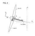
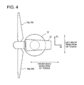
- FIG.2 , FIG.3 and FIG.4 each illustrate how to set coordinates in the wind turbine generator in the present specification.
- FIG.2 is a schematic perspective view of the blades 16 (16a, 16b) and a peripheral area of the blades 16.
- FIG.3 is a schematic side view of the blades 16 (16a, 16b) and the peripheral area of the blades 16.
- FIG.4 is a schematic top view of the blades 16 (16a, 16b) and the peripheral area of the blades 16.
- Xk axis, Yk axis and Zk axis are perpendicular to one another.
- Xk axis extends in the horizontal direction along a front-back direction of the tower 10.
- Yk axis extends in the horizontal direction along the width direction of the tower 10.
- Zk axis extends vertically.
- Xn axis, Yn axis and Zn axis extend perpendicular to one another.
- Xn axis extends along the rotation axis 14 and is oblique to the horizontal axis corresponding to the tilt angle.
- Yn axis extends horizontally along the width direction of the tower 10.
- Zn axis is oblique to the vertical direction corresponding to the tilt angle.
- FIG.5 illustrates a schematic structure of the control system of the wind turbine generator.
- the control system includes the control unit 20 and a sensor group.
- the control unit 20 controls the pitch drive mechanism 18 based on data measured by the sensor group.
- the sensor group includes a tower vibration meter 31, an azimuth angle sensor 32, and a blade load sensor 34.
- the tower vibration meter 31 is provided to detect the load impinging on the tower 10 in at least two directions.
- the tower vibration meter 31 is formed by a vibration meter installed in the tower 10 and is capable of measuring vibration in a front-back direction and in a left-right direction of the tower 10.
- the sensor group includes a nacelle vibration meter 33 (see FIG.1 ) for measuring the load impinging on the nacelle 12 in at least two directions, instead of the tower vibration meter 31.
- the nacelle vibration meter 33 is formed by a vibration meter installed in the nacelle 12 and is capable of measuring vibration in the front-back direction and the left-right direction of the nacelle 12.
- the azimuth angle sensor 32 is a sensor for measuring a rotation angle (the azimuth angle) of the rotation shaft 14.
- the azimuth angle sensor 32 is, for instance, formed by a rotary encoder and is installed adjacent to a part of the rotation shaft 14 that extends inside the nacelle 12.
- the azimuth angle is a rotation angle of the rotation shaft 14 in Yn-Zn plane.
- the blade load sensor 34 is a sensor for measuring the load impinging on the blade root of each blade 16.
- the blade load sensor 34 is formed by a first blade load sensor 34a for measuring the load impinging on the blade root of the first blade 16a, and a second blade load sensor 34b for measuring the load impinging on the blade root of the second blade 16b.
- the first blade load sensor 34a and the second blade load sensor 34b are attached to the blade roots of the first blade 16a and the second blade 16b, respectively.
- the first blade load sensor 16a and the second blade load sensor 16b are attached to the hub 28.
- the sensor group includes a pitch angle sensor 36 housed in the pitch drive mechanism 18.
- the pitch angle sensor 36 is formed by a first pitch angle sensor 36a for measuring the pitch angle of the first blade 16a and a second pitch angle sensor 36b for measuring the pitch angle of the second blade 16b.
- the sensor group includes a wind direction sensor 37 for measuring a wind direction in the periphery of the wind turbine generator, and a yaw angle sensor 38 housed in the yaw drive mechanism 30.
- the yaw angle sensor 38 is provided to measure the yaw angle of the nacelle 12.
- control unit 20 includes a Mzn moment calculation part 40, a Myn moment calculation part 42, a basic Mzn component calculation part 44, a basic Myn component calculation part 46, a correction Mzn component calculation part 48, a correction Myn component calculation part 50, a Mzn deviation calculation part 52, a Myn deviation calculation part 54, and a pitch angle adjustment amount determination part 56.
- the Mzn moment calculation part 40 calculates a Mzn moment impinging on the rotation shaft 14 around a vertical axis based on a load impinging on each of the blades 16 (16a, 16b) (Mzn moment calculation step).
- the Myn moment calculation part 42 calculates a Myn moment around the horizontal axis (Yn axis) impinging on the rotation shaft 14 based on the load impinging on each of the blades 16 (16a, 16b) (Myn moment calculation step).
- the load impinging on each of the blades 16 (16a, 16b) is measured by the blade load sensor 34 (34a, 34b) and then inputted to the control unit 20.
- the basic Mzn component calculation part 44 extracts a basic Mzn component from the Mzn moment calculated by the Mzn moment calculation part 40 (a basic Mzn component calculation step).
- the basic Mzn component includes at least a basic frequency component corresponding to the rotation speed of the rotation shaft 14 and a stationary component.
- the basic Mzn component is generated by the wind and is illustrated as the Mzn component in FIG.2 .
- the basic Myn component calculation part 46 extracts a basic Myn component from the Myn moment calculated by the Myn moment calculation part 42 (a basic Myn component calculation step).
- the basic Myn component includes at least the basic frequency component corresponding to the rotation speed of the rotation shaft 14 and a stationary component.
- the correction Mzn component calculation part 48 calculates a correction Mzn component which is a vertical component of the Mxn moment impinging on the rotation shaft 14 around the rotation shaft 14 (a correction Mzn calculation step).
- the correction Mzn component is illustrated as Mzn in FIG.3 .
- the correction Myn component calculation part 50 calculates a correction Myn component which is a horizontal component of a gyroscopic moment impinging on the rotation shaft 14 (a correction Myn calculation step).
- the Mzn deviation calculation part 52 calculates a Mzn deviation which is a difference between the basic Mzn component and the correction Mzn component (a Mzn deviation calculation step).
- the Myn deviation calculation part 54 calculates a Myn deviation which is a difference between the basic Myn component and the correction Myn component (a Myn deviation calculation step).
- the pitch angle adjustment amount determination part 56 determines the pitch angle adjustment amount of each of the blades 16 (16a, 16b) based on the Mzn deviation and the Myn deviation (a pitch angle adjustment amount determination step).
- the control unit 20 may be constituted of, for instance, a computer formed by a APU, a memory unit, an external storage, and an input-output unit.
- a control unit 20 may be constituted of, for instance, a computer formed by a APU, a memory unit, an external storage, and an input-output unit.
- the program stored in the external storage it is possible to achieve functions of the Mzn moment calculation part 40, the Myn moment calculation part 42, the basic Mzn component calculation part 44, the basic Myn component calculation part 46, the correction Mzn component calculation part 48, the correction Myn component calculation part 50, the Mzn deviation calculation part 52, the Myn deviation calculation part 54, and the pitch angle adjustment amount determination part 56.
- control unit 20 determines the pitch angle adjustment amount of the first blade 16a and the second blade 16b based on the data measured by the sensor group as illustrated in FIG.6 . Then, the pitch drive mechanism 18 adjusts the pitch angles of the first blade 16a and the second blade 16b based on the determined pitch angle adjustment amount.
- the azimuth angle, the load impinging on the blade root of the first blade 16a (the first blade load), the load impinging on the blade root of the second blade 16b (the second blade load), the yaw angle of the nacelle 12, the vibration of the tower 10 in the front-back direction and the vibration of the tower 10 in the left-right direction are inputted to the control unit 20,
- the control unit 20 includes a rotated-fixed coordinate transformation part 60 which forms the Mzn moment calculation part 40 and the Myn moment calculation part 42.
- the rotated-fixed coordinate transformation part 60 transforms the first blade load and the second blade load from rotated system coordinates to fixed system coordinates. Equation (1) described below represents the first blade load and the second blade load before the coordinate transformation. Equation (2) described below represents the first blade load and the second blade load after the coordinate transformation.
- F is an azimuth angle
- Mm is an amplitude of a variable component of the load on the blade root of the blade 16
- M01 is a stationary component of the load on the blade root of the first blade 16a
- M02 is a stationary component of the load of the blade root of the second blade 16b
- P is a circular constant
- D is a constant.
- M01 and M02 each indicate the load impinging on the blade root of each blade 16 (16a, 16b) resulting from imbalance in weight or location of center of gravity of the blade 16 (16a, 16b) or the hub 28.
- the control unit 20 further includes a Mzn notch filter 62a which forms the basic Mzn component calculation part 44.
- the Mzn notch filter 62a passes the basic frequency component corresponding to the second member (( M 01 - M 02 )sin F ) and the stationary component corresponding to the third member ( M m sin D ) of the Mzn moment which are on the right side of equation(2).
- the Mzn notch filter 62a is a band-stop filter that blocks a second harmonic component corresponding to the first member ( M m cos(2 F + D )) of the Mzn moment which is on the right side of equation (2).
- the control unit 20 includes a Myn notch filter 62b forming the basic Myn component calculation part 46.
- the Myn notch filter 62b passes the basic frequency component corresponding to the second member (( M 01 - M 02 )sin F ) and the stationary component corresponding to the third member ( M m sin D ) of the Myn moment which is on the right side of equation (2).
- the Myn notch filter 62b is a band-stop filter that blocks a second harmonic component corresponding to the first member ( M m cos(2 F + D )) of the Myn moment which is on the right side of equation (2).
- the control unit 20 includes a component composition-decomposition part 64 which forms the correction Mzn component calculation part 48 and the correction Myn component calculation part 50.
- the component composition-decomposition part 64 composes the vibration component in the front-back direction of the tower 10 and the vibration component in the left-right direction of the tower that have been inputted thereto, and then decomposes the components into the correction Mzn component and the correction Myn component.
- the nacelle 12 is rotatable and thus, the yaw angle of the nacelle 12 is also inputted to the component composition-decomposition part 64 and the component composition-decomposition part 64 performs composition and decomposition with consideration of the yaw angle as well.
- control unit 20 includes a Mzn LPF (Mzn Low Pass Filter) 66a which forms the correction Mzn component calculation part 48.
- the Mzn LPF 66a removes a high-frequency noise component from the correction Mzn component calculated by the component composition-decomposition part 64.
- control unit 20 includes a Myn LPF (Myn Low Pass Filter) 66b which forms the correction Myn component calculation part 50.
- Myn LPF 66b removes a high-frequency noise component from the correction Myn component calculated by the component composition-decomposition part 64.
- the control unit 20 includes a Mzn subtractor 68a which forms the Mzn deviation calculation part 52.
- the Mzn subtractor 68a calculates the Mzn deviation which is a difference between the basic Mzn component and the correction Mzn component.
- the control unit 20 further includes a Myn subtractor 68b which forms the Myn deviation calculation part 54.
- the Myn subtractor 68b calculates the Myn deviation which is a difference between the basic Myn component and the correction Myn component.
- control unit 20 includes a Mzn PI controller 70a, a Myn PI controller 70b and a rotated-fixed coordinate transformation part 72 which form the pitch angle adjustment amount determination part 56.
- the Mzn PI controller 70a is a proportional-integral controller for calculating a pitch angle operation amount in the fixed system coordinates so as to reduce the Mzn deviation, i.e. to bring the Mzn deviation close to zero.
- the Myn PI controller 70b is a proportional-integral controller for calculating a pitch angle operation amount in the fixed system coordinates so as to reduce the Myn deviation, i.e. to bring the Myn deviation close to zero.
- the rotated-fixed coordinate transformation part 72 transforms the pitch angle operation amounts calculated by the Mzn PI controller 70a and the Myn PI controller 70b into rotated system coordinates and based on this, determines the pitch angle adjustment amount of the first blade 16a and the pitch angle adjustment amount of the second blade 16b. Based on the pitch angle adjustment amount of the first blade 16a and the pitch angle adjustment amount of the second blade 16b determined in this manner, the first pitch drive mechanism 18a and the second pitch drive mechanism 18b adjust the pitch angle of the first blade 16a and the pitch angle of the second blade 16b, respectively.
- the Mzn deviation which is the difference between the basic Mzn component and the correction Mzn component, is calculated and based on this Mzn deviation, the pitch angle adjustment amount is determined.
- the correction Mzn component is a vertical component of the Mxn moment around the rotation shaft 14 impinging on the rotation shaft 14.
- the pitch angle adjustment amount is determined with consideration of the effect of the vertical component of the Mxn moment caused because the rotation shaft 14 is tilted with respect to the horizontal axis.
- the 1P component is expressed by the second member which is on the right side of equation (2), ((M 01 -M 02 )cos F, ( M 01 - M 02 )sin F ).
- the 1P component includes the difference between the load M01 and the load M02 and is the variable load component that causes imbalance resulting from the weight and location of center of gravity of the blade 16 (16a, 16b) or the hub 28.
- the third member on the right side of equation (2), ( M m cos D , M m sinD) indicates a component that is considered almost stationary, i.e. the stationary component.
- This stationary component includes information regarding Mm, i.e. information regarding variable amplitude of the load impinging on the blade root of the blade 16 (16a, 16b). The stationary component is compensated so that the variable load component of the 2P component impinging on the nacelle 12 and the tower 10 can be reduced.
- the control unit 20 includes a yaw angle adjustment amount determination part 58.
- the correction Mzn component calculation part 48 of the control unit 20 is capable of calculating the correction Mzn component based on the vibration of the tower 10 measured by the tower vibration meter 31 and the yaw angle of the nacelle 12.
- the correction Mzn component 48 of the control unit 20 is capable of calculating the correction Mzn component based on the vibration of the nacelle 12 measured by the nacelle vibration meter 33.
- the blade 16 is formed by two blades 16 (16a, 16b).
- a two-blade structure compared to a three-blade structure, mechanically has poor balance and a large variable load resulting from the gyroscopic moment, etc. affects the rotation shaft 14 and so on.
- the pitch angle adjustment amount is determined based on the Mzn deviation which is the difference between the basic Mzn component and the correction Mzn component, the variable load can be effectively reduced even in the case where the blade 16 is formed by two blades.
- the pitch angle adjustment amount of the blade 16 (16a, 16b) is determined based on the Mzn deviation and the Myn deviation.
- the Myn deviation is the difference between the basic Myn component and the correction Myn component and the correction Myn component is a horizontal component of the gyroscopic moment.
- the gyroscopic moment is generated when the rotating rotation shaft 14 is tilted. For instance, when the nacelle 12 rotates around the vertical axis for the yaw angle adjustment, the gyroscopic moment impinges on the rotation shaft 14 to tilt the rotation shaft 14 around the vertical axis and the axis perpendicular to the rotation shaft 14.
- large variable load is loaded on the connection part etc. which connects the blade 16 (16a, 16b) to the rotation shaft 14. It is desirable to reduce this variable load for the purpose of maintaining the operation life of the connection part, etc.
- the pitch angle adjustment amount of the blade 16 (16a, 16b) is determined with consideration of the effect of the horizontal component of the gyroscopic moment generated due to tilting of the rotation shaft 14.
- the basic frequency component (1P component) and the component not greater than the basic frequency (stationary component) that result from the title angle of the rotation shaft 14, the gyroscopic moment and uneven balance.
- the basic frequency component has frequency corresponding to the rotation speed of the rotation shaft 14.
- the pitch angle adjustment amount determination part 56 of the control unit 20 includes a proportioning controller 76, an integrating controller 78, and a periodic variation controller 80.
- the proportioning controller 76 outputs response to the input using a transfer function (Kp) of a proportional element.
- the integrating controller 78 outputs response to the input using a transfer function (Ki/s) of an integrating element.
- the periodic variation controller 80 outputs response to the input using a transfer function F (periodic transfer function: ks ⁇ s/(s ⁇ 2+Arot ⁇ 2) of a cosine wave component.
- Arot in the period transfer function is an angular speed of the rotation shaft 14.
- the proportioning controller 76 is formed by a Mzn proportioning controller 76a and a Myn proportioning controller 76b, the integrating controller 78 being formed by a Mzn integrating controller 78a and a Myn integrating controller, the periodic variation controller 80 being formed by a Mzn periodic variation controller 80a and a Myn periodic variation controller 80b.
- the Mzn deviation is inputted to the Mzn proportioning controller 76a, the Mzn integrating controller 78a and the Mzn periodic variation controller 80a
- the Myn deviation is inputted to the Myn proportioning controller 76b, the Myn integrating controller 78b and the Myn periodic variation controller 80b.
- the deviation can be reduced only to a certain extent.
- the load impinging on the blade 16 (16a, 16b) contains the component that periodically varies in a sinusoidal or cosinusoidal manner.
- the pitch angle adjustment amount is determined using the periodic variation transfer function and thus, even if the load impinging on the blade 16 (16a, 16b) contains the periodic variation component, it is possible to surely reduce the periodic variation component.
Landscapes
- Engineering & Computer Science (AREA)
- Physics & Mathematics (AREA)
- Fluid Mechanics (AREA)
- Life Sciences & Earth Sciences (AREA)
- Sustainable Development (AREA)
- Sustainable Energy (AREA)
- Chemical & Material Sciences (AREA)
- Combustion & Propulsion (AREA)
- Mechanical Engineering (AREA)
- General Engineering & Computer Science (AREA)
- Wind Motors (AREA)
Abstract
Description
- The present invention relates to a wind turbine generator, a control unit and a control method for the wind turbine generator. More specifically, the present invention relates to a wind turbine generator, a control unit and a control method for the wind turbine generator, which make it possible to adjust a pitch angle of a blade.
- In recent years, wind turbine generators for generating electric power using wind in a form of renewable energy have come into wide use from the perspective of preserving the environment. In a wind turbine generator, a force of wind impinging on the blade is converted to a rotational force of a rotation shaft, which is then converted to electrical power by a generator.
In a wind turbine generator, the wind impinging on the blade is uneven temporally and spatially, and thus the moment (a tilt moment) which impinges to tilt the rotation shaft impinges on the blade in some cases. - Patent Literature 1 describes a technique, in a wind turbine generator, for achieving extended operation time of a main bearing by reducing the mean bending moment on the bearing by means of a tilt moment on the rotor generated by means of aerodynamic forces on the blades.
- More specifically, in the wind turbine generator of Patent Literature 1, data of the wind turbine generator are measured with pitch position sensors, blade load sensors and azimuth sensors. The measured sensor data are supplied to a computing unit where the data is converted to a feedback signal. The feedback signal is used in feedback control to control the pitch angle ([0055] of Patent Literature 1).
- PTL 1
US 2010/0014971 A - In a typical wind turbine generator, the rotation shaft is tilted approximately at 5 degrees with respect to a horizontal axis of the rotation shaft to avoid collision between the blade and the tower. As the rotation shaft is tilted, the rotation moment around the rotation shaft includes a vertical component. This vertical component of the moment around the rotation shaft affects the tilt moment impinging on the rotation shaft and also affects the variable load impinging on the blade root.
- In Patent Literature 1, there is no mention of these effects or countermeasures against these effects.
It is an object of at least one embodiment of the present invention to provide a wind turbine generator, and a control unit and a control method for the wind turbine generator, which make it possible to suppress variable load impinging on the blade root and to improve durability of the wind turbine generator. - A wind turbine generator according to at least one embodiment of the present invention comprises:
- a tower;
- a nacelle supported by the tower;
- a rotation shaft rotatably supported by the nacelle in such a state that the rotation shaft is tilted with respect to a horizontal axis;
- at least two blades provided for the rotation shaft with a pitch angle of each of the blades around an axis along a radial direction of the rotation shaft being adjustable;
- a pitch drive mechanism for adjusting the pitch angle of each of the blades; and
- a control unit configured to determine an adjustment amount of the pitch angle by which the pitch drive mechanism is configured to adjust the pitch angle,
- a Mzn moment calculation part for calculating a Mzn moment impinging on the rotation shaft around a vertical axis based on a load impinging on each of the plurality of blades;
- a basic Mzn component calculation part for extracting a basic Mzn component from the Mzn moment, the basic Mzn component comprising at least a basic frequency component corresponding to a rotation speed of the rotation shaft and a stationary component;
- a correction Mzn component calculation part for calculating a correction Mzn component which is a vertical component of the Mxn moment impinging on the rotation shaft around the rotation shaft; and
- a pitch angle adjustment amount determination part for calculating a Mzn deviation which is a difference between the basic Mzn component and the correction Mzn component and determining the adjustment amount of the pitch angle of each of the blades based on the Mzn deviation.
- In the above wind turbine generator, the Mzn deviation, which is the difference between the basic Mzn component and the correction Mzn component, is calculated and based on this Mzn deviation, the pitch angle adjustment amount is determined. The correction Mzn component is a vertical component of the Mxn moment around the rotation shaft impinging on the rotation shaft. According to this configuration, the pitch angle adjustment amount is determined with consideration of the effect of the vertical component of the Mxn moment caused because the rotation shaft is tilted with respect to the horizontal axis. By adjusting the pitch angle based on the pitch angle adjustment amount determined in this manner, the variable load impinging on the blade root of the blade is effectively suppressed and the durability of the wind turbine generator is improved.
- In some embodiments, the pitch angle adjustment amount determination unit is configured to determine the adjustment amount of the pitch angle using the Mzn deviation and a periodic variation transfer function.
In the case of PI control, normally when the control amount varies periodically in a sinusoidal or cosinusoidal manner, the deviation can be reduced only to a certain extent. By increasing a gain, it is possible to make the deviation smaller. However, the larger gain may make the control unstable. The load impinging on the blade contains the component that periodically varies in a sinusoidal or cosinusoidal manner. Thus, solely by PI control, the variable component impinging on the blade can be reduced only to a certain extent.
In this structure, the pitch angle adjustment amount is determined using the periodic variation transfer function and thus, even if the load impinging on the blade contains the periodic variation component, it is possible to surely reduce the periodic variation component. - In some embodiments, the wind turbine generator further comprises:
- at least one vibration meter for measuring vibration of the tower in at least two directions; and
- a yaw drive mechanism for adjusting a yaw angle of the nacelle,
- wherein the correction Mzn component calculation part is configured to calculate the correction Mzn component based on the vibration of the tower measured by the vibration meter and the yaw angle of the nacelle.
- In some embodiments, the wind turbine generator further comprises:
- at least one vibration meter for measuring vibration of the nacelle in at least two directions,
- wherein the correction Mzn component calculation part is configured to calculate the correction Mzn component based on the vibration of the nacelle measured by the vibration meter.
- In some embodiments, the blades comprise two blades.
Normally, a two-blade structure, compared to a three-blade structure, mechanically has poor balance and a large variable load resulting from the gyroscopic moment, etc. affects the rotation shaft and so on.
In this aspect, in the above structure where the pitch angle adjustment amount is determined based on the Mzn deviation which is the difference between the basic Mzn component and the correction Mzn component, the variable load can be effectively reduced even in the case where the blade is formed by two blades. - The above-described control unit further comprises:
- a Myn moment calculation part for calculating a Myn moment impinging on the rotation shaft around a horizontal axis based on a load impinging on each of the blades;
- a basic Myn component calculation part for extracting a basic Myn component from the Myn moment, the basic Myn component comprising at least a basic frequency component corresponding to the rotation speed of the rotation shaft and a stationary component; and
- a correction Myn component calculation part for calculating a correction Myn component which is a horizontal component of a gyroscopic moment impinging on the rotation shaft,
- wherein the pitch angle adjustment amount determination part is configured to calculate a Myn deviation which is a difference between the basic Myn component and the correction Myn component and determine the adjustment amount of the pitch angle of each of the blades based on the Mzn deviation and the Myn deviation.
- In this structure, the pitch angle adjustment amount of the blade is determined based on the Mzn deviation and the Myn deviation. The Myn deviation is a difference between the basic Myn component and the correction Myn component and the correction Myn component is a horizontal component of a gyroscopic moment. According to this c, the pitch angle adjustment amount is determined with consideration of the effect of the horizontal component of the gyroscopic moment generated due to tilting of the rotation shaft. By adjusting the pitch angle based on the pitch angle adjustment amount determined in this manner, the variable load impinging on the rotation shaft, etc. can be suppressed effectively and the durability of the wind turbine generator is improved.
- The pitch angle adjustment amount determination part is configured to determine the adjustment amount of the pitch angle of each of the blades using the Mzn deviation, the Myn deviation and a periodic variation transfer function.
In this structure, the pitch angle adjustment amount is determined using the periodic variation transfer function and thus, even if the load impinging on the blade contains the periodic variation component, it is possible to surely reduce the periodic variation component. - A control method, according to at least one embodiment of the present invention, is for a wind turbine generator which comprises: a tower; a nacelle supported by the tower; a rotation shaft rotatably supported by the nacelle in such a state that the rotation shaft is tilted with respect to a horizontal axis; at least two blades provided for the rotation shaft with a pitch angle of each of the blades around an axis along a radial direction of the rotation shaft being adjustable; and a pitch drive mechanism for adjusting the pitch angle of each of the blades. The control method comprises:
- a Mzn moment calculation step of calculating a Mzn moment impinging on the rotation shaft around a vertical axis based on a load impinging on each of the blades;
- a basic Mzn component calculation step of extracting a basic Mzn component from the Mzn moment, the basic Mzn component comprising a basic frequency component corresponding to a rotation speed of the rotation shaft and a stationary component;
- a correction Mzn component calculation step of calculating a correction Mzn component which is a vertical component of the Mxn moment impinging on the rotation shaft around the rotation shaft; and
- an adjustment amount determination step of calculating a Mzn deviation which is a difference between the basic Mzn component and the correction Mzn component and determining an adjustment amount of the pitch angle of each of the blades based on the Mzn deviation.
- According to the above control method for the wind turbine generator, the Mzn deviation, which is the difference between the basic Mzn component and the correction Mzn component, is calculated and based on this Mzn deviation, the pitch angle adjustment amount is determined. The correction Mzn component is a vertical component of the Mxn moment around the rotation shaft impinging on the rotation shaft. According to this configuration, the pitch angle adjustment amount is determined with consideration of the effect of the vertical component of the Mxn moment caused because the rotation shaft is tilted with respect to the horizontal axis. By adjusting the pitch angle based on the pitch angle adjustment amount determined in this manner, the variable load impinging on the blade root of the blade is effectively suppressed and the durability of the wind turbine generator is improved.
- In some embodiments, in the adjustment amount determination step, the adjustment amount of the pitch angle is determined using the Mzn deviation and a periodic variation transfer function.
In this structure, the pitch angle adjustment amount is determined using the periodic variation transfer function and thus, even if the load impinging on the blade contains the periodic variation component, it is possible to surely reduce the periodic variation component. - In some embodiments, the wind turbine generator further comprises a yaw drive mechanism for adjusting a yaw angle of the nacelle, and
in the correction Mzn component calculation step, the correction Mzn component is calculated based on vibration of the tower in at least two directions and the yaw angle of the nacelle. - In some embodiments, in the correction Mzn component calculation step, the correction Mzn component is calculated based on vibration of the nacelle in at least two directions.
- In some embodiments, the control method for the wind turbine generator further comprises:
- a Myn moment calculation step of calculating a Myn moment impinging on the rotation shaft around a horizontal axis based on a load impinging on each of the blades;
- a basic Myn component calculation part for extracting a basic Myn component from the Myn moment by removing a high-frequency component having frequency higher than a basic frequency component corresponding to the rotation speed of the rotation shaft, the basic Myn component comprising the basic frequency component and a stationary component; and
- a correction Myn component calculation step of calculating a correction Myn component which is a horizontal component impinging on the rotation shaft around a horizontal axis due to a gyroscopic moment impinging on the rotation shaft,
- wherein, in the adjustment amount determination step, a Myn deviation which is a difference between the basic Myn component and the correction Myn component is calculated and the adjustment amount of the pitch angle of each of the blades is determined based on the Mzn deviation and the Myn deviation.
- In this structure, the pitch angle adjustment amount of the blade is determined based on the Mzn deviation and the Myn deviation. The Myn deviation is a difference between the basic Myn component and the correction Myn component and the correction Myn component is a horizontal component of a gyroscopic moment. According to this c, the pitch angle adjustment amount is determined with consideration of the effect of the horizontal component of the gyroscopic moment generated due to tilting of the rotation shaft. By adjusting the pitch angle based on the pitch angle adjustment amount determined in this manner, the variable load impinging on the rotation shaft, etc. can be suppressed effectively and the durability of the wind turbine generator is improved.
- In some embodiments, in the adjustment amount determination step, the adjustment amount of the pitch angle of each of the blades is determined using the Mzn deviation, the Myn deviation and a periodic variation transfer function.
In this structure, the pitch angle adjustment amount is determined using the periodic variation transfer function and thus, even if the load impinging on the blade contains the periodic variation component, it is possible to surely reduce the periodic variation component. - A control unit, according to the present invention, for a wind turbine generator which comprises: a tower; a nacelle supported by the tower; a rotation shaft rotatably supported by the nacelle in such a state that the rotation shaft is tilted with respect to a horizontal axis; at least two blades provided for the rotation shaft with a pitch angle of each of the blades around an axis along a radial direction of the rotation shaft being adjustable ; and a pitch drive mechanism for adjusting the pitch angle of each of the blades, comprises:
- a Mzn moment calculation part for calculating a Mzn moment impinging on the rotation shaft around a vertical axis based on a load impinging on each of the blades;
- a basic Mzn component calculation part for extracting a basic Mzn component from the Mzn moment, the basic Mzn component comprising a basic frequency component corresponding to a rotation speed of the rotation shaft and a stationary component;
- a correction Mzn component calculation part for calculating a correction Mzn component which is a vertical component of the Mxn moment impinging on the rotation shaft around the rotation shaft; and
- a pitch angle adjustment amount determination part for calculating a Mzn deviation which is a difference between the basic Mzn component and the correction Mzn component and determining an adjustment amount of the pitch angle of each of the blades based on the Mzn deviation.
- In the above control unit for the wind turbine generator, the Mzn deviation, which is the difference between the basic Mzn component and the correction Mzn component, is calculated and based on this Mzn deviation, the pitch angle adjustment amount is determined. The correction Mzn component is a vertical component of the Mxn moment around the rotation shaft impinging on the rotation shaft. According to this configuration, the pitch angle adjustment amount is determined with consideration of the effect of the vertical component of the Mxn moment caused because the rotation shaft is tilted with respect to the horizontal axis. By adjusting the pitch angle based on the pitch angle adjustment amount determined in this manner, the variable load impinging on the blade root of the blade is effectively suppressed and the durability of the wind turbine generator is improved.
- According to at least one embodiment of the present invention, provided is a wind turbine generator, a control unit for the wind turbine generator and a control method for the wind turbine generator which make it possible to suppress the variable load impinging on the blade root of the blade and also to improve durability of the wind turbine generator.
-
- [
FIG.1] FIG. 1 is a schematic view of a structure of a wind turbine generator according to some embodiments of the present invention. - [
FIG.2] FIG.2 is a schematic oblique view of blades of the wind turbine generator 1, illustrating how to set coordinates around the blades. - [
FIG.3] FIG.3 is a schematic side view of blades of the wind turbine generator 1, illustrating how to set coordinates around the blades. - [
FIG.4] FIG.4 is a schematic side view of blades of the wind turbine generator 1, illustrating how to set coordinates around the blades. - [
FIG.5] FIG.5 is a block diagram schematically illustrating a control system used in the wind turbine generator ofFIG.1 . - [
FIG.6] FIG.6 is a block diagram schematically illustrating a structure of a control unit ofFIG. 5 . - [
FIG.7] FIG.7 is a block diagram schematically illustrating a structure of a control unit according to another embodiment. - Embodiments of the present invention will now be described in detail with reference to the accompanying drawings. It is intended, however, that unless particularly specified in these embodiments, dimensions, materials, shape, its relative positions and the like shall be interpreted as illustrative only and not limitative of the scope of the present invention.
-
FIG.1 is a schematic view of a structure of a wind turbine generator according to some embodiments of the present invention. As illustrated inFIG.1 , the wind turbine generator 1 is provided with atower 10, anacelle 12 supported by thetower 10, arotation shaft 14 rotatably supported by thenacelle 12 in such a state that therotation shaft 14 is tilted relative to the horizontal axis, at least twoblades 16 provided for therotation shaft 14 so that its pitch angle around an axis along the radial direction of therotation shaft 14 is adjustable, apitch drive mechanism 18 for adjusting the pitch angle of each of theblades 16, and acontrol unit 20 configured to determine a pitch angle adjustment amount to be adjusted by thepitch drive mechanism 18. - In some embodiments, the wind turbine generator is provided with a bearing 22 installed in the
nacelle 12, aspeed increasing mechanism 24, and agenerator 26. Therotation shaft 14 is rotatably supported by the bearing 22. Therotation shaft 14 is rotated when the wind hits the blade. Therotation shaft 14 is connected to the speed-increasingmechanism 24 and the speed-increasingmechanism 24 is connected to thegenerator 26. Thespeed increasing mechanism 24 is configured to increase the rotation speed of therotation shaft 24 and then transfer it to thegenerator 26. - In some embodiments, the
speed increasing mechanism 24 is formed by ahydraulic pump 24a and ahydraulic motor 24b and therotation shaft 14 is connected to thehydraulic pump 24a. Thehydraulic pump 24a compresses operating oil using the rotation of therotation shaft 14 resulting from the wind energy, and then supplies the high pressure operating oil to thehydraulic motor 24b. Thehydraulic motor 24b includes an output shaft connected to thegenerator 26. Thehydraulic motor 24b rotates the output shaft using the high pressure operating oil supplied from thehydraulic pump 24a so as to cause thegenerator 26 to generate electric power. The operating oil having performed work in thehydraulic motor 24b undergoes pressure decrease and the operating oil returns to thehydraulic pump 24a.
In some embodiments, thespeed increasing mechanism 24 is formed of a planetary gear mechanism.
In some embodiments, therotation shaft 14 is directly connected to thegenerator 26 without thespeed increasing mechanism 24. - The
tower 10 is, for instance, installed on the ground or offshore. In some embodiments, the wind turbine generator is provided with ayaw drive mechanism 30 being capable of adjusting the yaw angle of thenacelle 12 around the vertical axis and thecontrol unit 20 is configured to determine the adjustment amount of the yaw angle according to the wind direction.
In some embodiments, the two ormore blades 16 is constituted of afirst blade 16a and asecond blade 16b and thefirst blade 16a and thesecond blade 16b are connected to therotation shaft 14 via a T-shapedhub 28. Thepitch drive mechanism 18 is formed by a firstpitch drive mechanism 18a for thefirst blade 16a and a secondpitch drive mechanism 18b for thesecond blade 16b. The firstpitch drive mechanism 18a is provided in a connection part between thefirst blade 16a and thehub 28. The secondpitch drive mechanism 18b is provided in a connection part between thesecond blade 16b and thehub 28. -
FIG.2 ,FIG.3 andFIG.4 each illustrate how to set coordinates in the wind turbine generator in the present specification.FIG.2 is a schematic perspective view of the blades 16 (16a, 16b) and a peripheral area of theblades 16.FIG.3 is a schematic side view of the blades 16 (16a, 16b) and the peripheral area of theblades 16.FIG.4 is a schematic top view of the blades 16 (16a, 16b) and the peripheral area of theblades 16.
As illustrated inFIG.2 to FIG.4 , Xk axis, Yk axis and Zk axis are perpendicular to one another. Xk axis extends in the horizontal direction along a front-back direction of thetower 10. Yk axis extends in the horizontal direction along the width direction of thetower 10. Zk axis extends vertically.
Xn axis, Yn axis and Zn axis extend perpendicular to one another. Xn axis extends along therotation axis 14 and is oblique to the horizontal axis corresponding to the tilt angle. Yn axis extends horizontally along the width direction of thetower 10. Zn axis is oblique to the vertical direction corresponding to the tilt angle. -
FIG.5 illustrates a schematic structure of the control system of the wind turbine generator.
As illustrated inFIG.5 , in some embodiments, the control system includes thecontrol unit 20 and a sensor group. Thecontrol unit 20 controls thepitch drive mechanism 18 based on data measured by the sensor group.
In some embodiments, the sensor group includes atower vibration meter 31, anazimuth angle sensor 32, and ablade load sensor 34. - The
tower vibration meter 31 is provided to detect the load impinging on thetower 10 in at least two directions. In some embodiments, thetower vibration meter 31 is formed by a vibration meter installed in thetower 10 and is capable of measuring vibration in a front-back direction and in a left-right direction of thetower 10.
In some embodiments, the sensor group includes a nacelle vibration meter 33 (seeFIG.1 ) for measuring the load impinging on thenacelle 12 in at least two directions, instead of thetower vibration meter 31. Thenacelle vibration meter 33 is formed by a vibration meter installed in thenacelle 12 and is capable of measuring vibration in the front-back direction and the left-right direction of thenacelle 12. - The
azimuth angle sensor 32 is a sensor for measuring a rotation angle (the azimuth angle) of therotation shaft 14. Theazimuth angle sensor 32 is, for instance, formed by a rotary encoder and is installed adjacent to a part of therotation shaft 14 that extends inside thenacelle 12. The azimuth angle is a rotation angle of therotation shaft 14 in Yn-Zn plane. - The
blade load sensor 34 is a sensor for measuring the load impinging on the blade root of eachblade 16. In some embodiments, theblade load sensor 34 is formed by a firstblade load sensor 34a for measuring the load impinging on the blade root of thefirst blade 16a, and a secondblade load sensor 34b for measuring the load impinging on the blade root of thesecond blade 16b. The firstblade load sensor 34a and the secondblade load sensor 34b are attached to the blade roots of thefirst blade 16a and thesecond blade 16b, respectively.
In some embodiments, the firstblade load sensor 16a and the secondblade load sensor 16b are attached to thehub 28. - In some embodiments, the sensor group includes a pitch angle sensor 36 housed in the
pitch drive mechanism 18. The pitch angle sensor 36 is formed by a firstpitch angle sensor 36a for measuring the pitch angle of thefirst blade 16a and a secondpitch angle sensor 36b for measuring the pitch angle of thesecond blade 16b.
In some embodiments, the sensor group includes awind direction sensor 37 for measuring a wind direction in the periphery of the wind turbine generator, and ayaw angle sensor 38 housed in theyaw drive mechanism 30. Theyaw angle sensor 38 is provided to measure the yaw angle of thenacelle 12. - In some embodiments, the
control unit 20 includes a Mznmoment calculation part 40, a Mynmoment calculation part 42, a basic Mzncomponent calculation part 44, a basic Myncomponent calculation part 46, a correction Mzncomponent calculation part 48, a correction Myncomponent calculation part 50, a Mzndeviation calculation part 52, a Myndeviation calculation part 54, and a pitch angle adjustmentamount determination part 56. - The Mzn
moment calculation part 40 calculates a Mzn moment impinging on therotation shaft 14 around a vertical axis based on a load impinging on each of the blades 16 (16a, 16b) (Mzn moment calculation step). The Mynmoment calculation part 42 calculates a Myn moment around the horizontal axis (Yn axis) impinging on therotation shaft 14 based on the load impinging on each of the blades 16 (16a, 16b) (Myn moment calculation step). The load impinging on each of the blades 16 (16a, 16b) is measured by the blade load sensor 34 (34a, 34b) and then inputted to thecontrol unit 20. - The basic Mzn
component calculation part 44 extracts a basic Mzn component from the Mzn moment calculated by the Mzn moment calculation part 40 (a basic Mzn component calculation step). The basic Mzn component includes at least a basic frequency component corresponding to the rotation speed of therotation shaft 14 and a stationary component. The basic Mzn component is generated by the wind and is illustrated as the Mzn component inFIG.2 .
The basic Myncomponent calculation part 46 extracts a basic Myn component from the Myn moment calculated by the Myn moment calculation part 42 (a basic Myn component calculation step). The basic Myn component includes at least the basic frequency component corresponding to the rotation speed of therotation shaft 14 and a stationary component. - The correction Mzn
component calculation part 48 calculates a correction Mzn component which is a vertical component of the Mxn moment impinging on therotation shaft 14 around the rotation shaft 14 (a correction Mzn calculation step). The correction Mzn component is illustrated as Mzn inFIG.3 .
The correction Myncomponent calculation part 50 calculates a correction Myn component which is a horizontal component of a gyroscopic moment impinging on the rotation shaft 14 (a correction Myn calculation step). - The Mzn
deviation calculation part 52 calculates a Mzn deviation which is a difference between the basic Mzn component and the correction Mzn component (a Mzn deviation calculation step).
The Myndeviation calculation part 54 calculates a Myn deviation which is a difference between the basic Myn component and the correction Myn component (a Myn deviation calculation step).
The pitch angle adjustmentamount determination part 56 determines the pitch angle adjustment amount of each of the blades 16 (16a, 16b) based on the Mzn deviation and the Myn deviation (a pitch angle adjustment amount determination step). - The
control unit 20 may be constituted of, for instance, a computer formed by a APU, a memory unit, an external storage, and an input-output unit. In this case, by running the program stored in the external storage, it is possible to achieve functions of the Mznmoment calculation part 40, the Mynmoment calculation part 42, the basic Mzncomponent calculation part 44, the basic Myncomponent calculation part 46, the correction Mzncomponent calculation part 48, the correction Myncomponent calculation part 50, the Mzndeviation calculation part 52, the Myndeviation calculation part 54, and the pitch angle adjustmentamount determination part 56. - The method for controlling the pitch angle of the blade 16 (16a, 16b), which is performed by the
control unit 20, is explained below. In some embodiments, thecontrol unit 20 determines the pitch angle adjustment amount of thefirst blade 16a and thesecond blade 16b based on the data measured by the sensor group as illustrated inFIG.6 . Then, thepitch drive mechanism 18 adjusts the pitch angles of thefirst blade 16a and thesecond blade 16b based on the determined pitch angle adjustment amount.
More specifically, as illustrated inFIG.6 , the azimuth angle, the load impinging on the blade root of thefirst blade 16a (the first blade load), the load impinging on the blade root of thesecond blade 16b (the second blade load), the yaw angle of thenacelle 12, the vibration of thetower 10 in the front-back direction and the vibration of thetower 10 in the left-right direction are inputted to thecontrol unit 20, - The
control unit 20 includes a rotated-fixed coordinatetransformation part 60 which forms the Mznmoment calculation part 40 and the Mynmoment calculation part 42. The rotated-fixed coordinatetransformation part 60 transforms the first blade load and the second blade load from rotated system coordinates to fixed system coordinates. Equation (1) described below represents the first blade load and the second blade load before the coordinate transformation. Equation (2) described below represents the first blade load and the second blade load after the coordinate transformation.
In equation (1) and equation (2), F is an azimuth angle, Mm is an amplitude of a variable component of the load on the blade root of theblade 16, M01 is a stationary component of the load on the blade root of thefirst blade 16a, M02 is a stationary component of the load of the blade root of thesecond blade 16b, P is a circular constant, D is a constant. M01 and M02 each indicate the load impinging on the blade root of each blade 16 (16a, 16b) resulting from imbalance in weight or location of center of gravity of the blade 16 (16a, 16b) or thehub 28.

- The
control unit 20 further includes aMzn notch filter 62a which forms the basic Mzncomponent calculation part 44. TheMzn notch filter 62a passes the basic frequency component corresponding to the second member ((M 01-M 02)sinF) and the stationary component corresponding to the third member (Mm sinD) of the Mzn moment which are on the right side of equation(2). In other words, theMzn notch filter 62a is a band-stop filter that blocks a second harmonic component corresponding to the first member (Mm cos(2F+D)) of the Mzn moment which is on the right side of equation (2). - The
control unit 20 includes aMyn notch filter 62b forming the basic Myncomponent calculation part 46. TheMyn notch filter 62b passes the basic frequency component corresponding to the second member ((M 01-M 02)sinF) and the stationary component corresponding to the third member (Mm sinD) of the Myn moment which is on the right side of equation (2). In other words, theMyn notch filter 62b is a band-stop filter that blocks a second harmonic component corresponding to the first member (Mm cos(2F+D)) of the Myn moment which is on the right side of equation (2). - The
control unit 20 includes a component composition-decomposition part 64 which forms the correction Mzncomponent calculation part 48 and the correction Myncomponent calculation part 50. The component composition-decomposition part 64 composes the vibration component in the front-back direction of thetower 10 and the vibration component in the left-right direction of the tower that have been inputted thereto, and then decomposes the components into the correction Mzn component and the correction Myn component.
In some embodiments, thenacelle 12 is rotatable and thus, the yaw angle of thenacelle 12 is also inputted to the component composition-decomposition part 64 and the component composition-decomposition part 64 performs composition and decomposition with consideration of the yaw angle as well. - In some embodiments, the
control unit 20 includes a Mzn LPF (Mzn Low Pass Filter) 66a which forms the correction Mzncomponent calculation part 48. TheMzn LPF 66a removes a high-frequency noise component from the correction Mzn component calculated by the component composition-decomposition part 64.
In some embodiments, thecontrol unit 20 includes a Myn LPF (Myn Low Pass Filter) 66b which forms the correction Myncomponent calculation part 50. TheMyn LPF 66b removes a high-frequency noise component from the correction Myn component calculated by the component composition-decomposition part 64. - The
control unit 20 includes aMzn subtractor 68a which forms the Mzndeviation calculation part 52. TheMzn subtractor 68a calculates the Mzn deviation which is a difference between the basic Mzn component and the correction Mzn component.
Thecontrol unit 20 further includes aMyn subtractor 68b which forms the Myndeviation calculation part 54. TheMyn subtractor 68b calculates the Myn deviation which is a difference between the basic Myn component and the correction Myn component. - Further, the
control unit 20 includes aMzn PI controller 70a, aMyn PI controller 70b and a rotated-fixed coordinatetransformation part 72 which form the pitch angle adjustmentamount determination part 56.
TheMzn PI controller 70a is a proportional-integral controller for calculating a pitch angle operation amount in the fixed system coordinates so as to reduce the Mzn deviation, i.e. to bring the Mzn deviation close to zero.
Further, theMyn PI controller 70b is a proportional-integral controller for calculating a pitch angle operation amount in the fixed system coordinates so as to reduce the Myn deviation, i.e. to bring the Myn deviation close to zero. - The rotated-fixed coordinate
transformation part 72 transforms the pitch angle operation amounts calculated by theMzn PI controller 70a and theMyn PI controller 70b into rotated system coordinates and based on this, determines the pitch angle adjustment amount of thefirst blade 16a and the pitch angle adjustment amount of thesecond blade 16b.
Based on the pitch angle adjustment amount of thefirst blade 16a and the pitch angle adjustment amount of thesecond blade 16b determined in this manner, the firstpitch drive mechanism 18a and the secondpitch drive mechanism 18b adjust the pitch angle of thefirst blade 16a and the pitch angle of thesecond blade 16b, respectively. - In the wind turbine generator in relation to the above-described embodiments, the Mzn deviation, which is the difference between the basic Mzn component and the correction Mzn component, is calculated and based on this Mzn deviation, the pitch angle adjustment amount is determined. The correction Mzn component is a vertical component of the Mxn moment around the
rotation shaft 14 impinging on therotation shaft 14. According to this configuration, the pitch angle adjustment amount is determined with consideration of the effect of the vertical component of the Mxn moment caused because therotation shaft 14 is tilted with respect to the horizontal axis. By adjusting the pitch angle based on the pitch angle adjustment amount determined in this manner, the variable load impinging on the blade root of the blade 16 (16a, 16b) is effectively suppressed and the durability of the wind turbine generator is improved.
In other words, by adjusting the tilt angle based on the load impinging on the blade root of the blade 16 (16a, 16b) and the load impinging on other part of the blade 16 (16a, 16b), it is possible to reduce the basic frequency component (1P component) corresponding to the rotation speed of the blade 16 (16a, 16b) together with a double frequency component (2P component) of the variable load impinging on thenacelle 12 and thetower 10. The double frequency component (2P component) has frequency twice as high as the basic frequency component. By reducing both the 2P component and the 1P component in this manner, it is possible to reduce the fatigue load impinging on thetower 10 and on thenacelle 12 and the durability of the wind turbine generator is improved. - The 1P component is expressed by the second member which is on the right side of equation (2), ((M 01 -M 02)cosF, (M 01-M 02)sinF). The 1P component includes the difference between the load M01 and the load M02 and is the variable load component that causes imbalance resulting from the weight and location of center of gravity of the blade 16 (16a, 16b) or the
hub 28.
Further, the third member on the right side of equation (2), (Mm cosD, MmsinD) indicates a component that is considered almost stationary, i.e. the stationary component. This stationary component includes information regarding Mm, i.e. information regarding variable amplitude of the load impinging on the blade root of the blade 16 (16a, 16b). The stationary component is compensated so that the variable load component of the 2P component impinging on thenacelle 12 and thetower 10 can be reduced. - In the wind turbine generator according to some embodiments, the
control unit 20 includes a yaw angle adjustmentamount determination part 58. By adjusting the yaw angle of thenacelle 12 corresponding to the wind direction by means of the yaw angle adjustmentamount determination part 58, it is possible to produce electric power effectively. The correction Mzncomponent calculation part 48 of thecontrol unit 20 is capable of calculating the correction Mzn component based on the vibration of thetower 10 measured by thetower vibration meter 31 and the yaw angle of thenacelle 12. - In the wind turbine generator according to some embodiments, the
correction Mzn component 48 of thecontrol unit 20 is capable of calculating the correction Mzn component based on the vibration of thenacelle 12 measured by thenacelle vibration meter 33. - In the wind turbine generator according to some embodiments, the
blade 16 is formed by two blades 16 (16a, 16b). Normally, a two-blade structure, compared to a three-blade structure, mechanically has poor balance and a large variable load resulting from the gyroscopic moment, etc. affects therotation shaft 14 and so on.
In this aspect, in the above structure where the pitch angle adjustment amount is determined based on the Mzn deviation which is the difference between the basic Mzn component and the correction Mzn component, the variable load can be effectively reduced even in the case where theblade 16 is formed by two blades. - In the wind turbine generator according to some embodiments, the pitch angle adjustment amount of the blade 16 (16a, 16b) is determined based on the Mzn deviation and the Myn deviation. The Myn deviation is the difference between the basic Myn component and the correction Myn component and the correction Myn component is a horizontal component of the gyroscopic moment.
The gyroscopic moment is generated when therotating rotation shaft 14 is tilted. For instance, when thenacelle 12 rotates around the vertical axis for the yaw angle adjustment, the gyroscopic moment impinges on therotation shaft 14 to tilt therotation shaft 14 around the vertical axis and the axis perpendicular to therotation shaft 14. When the gyroscopic moment occurs, large variable load is loaded on the connection part etc. which connects the blade 16 (16a, 16b) to therotation shaft 14. It is desirable to reduce this variable load for the purpose of maintaining the operation life of the connection part, etc. - In this aspect, in the wind turbine generator according to some embodiments, by determining the pitch angle adjustment amount of the blade 16 (16a, 16b) based on the Mzn deviation and the Myn deviation, the pitch angle adjustment amount is determined with consideration of the effect of the horizontal component of the gyroscopic moment generated due to tilting of the
rotation shaft 14. By adjusting the pitch angle based on the pitch angle adjustment amount determined in this manner, the variable load impinging on therotation shaft 14, etc. can be suppressed effectively and the durability of the wind turbine generator is improved.
Therefore, according to this structure, even if the gyroscopic moment is generated due to adjustment of the yaw angle, the variable load resulting from the gyroscopic moment can be suppressed by adjusting the pitch angle. - More specifically, according to this structure, it is possible to suppress the basic frequency component (1P component) and the component not greater than the basic frequency (stationary component) that result from the title angle of the
rotation shaft 14, the gyroscopic moment and uneven balance. Further, the basic frequency component has frequency corresponding to the rotation speed of therotation shaft 14. - In some embodiments, as illustrated in
FIG.7 , the pitch angle adjustmentamount determination part 56 of thecontrol unit 20 includes aproportioning controller 76, an integratingcontroller 78, and aperiodic variation controller 80. Theproportioning controller 76 outputs response to the input using a transfer function (Kp) of a proportional element. The integratingcontroller 78 outputs response to the input using a transfer function (Ki/s) of an integrating element. Then, theperiodic variation controller 80 outputs response to the input using a transfer function F (periodic transfer function: ks· s/(s^2+Arot^2) of a cosine wave component. The outputs from theproportioning controller 76, the integratingcontroller 78 and theperiodic variation controller 80 are added by an adder and then inputted to the rotated-fixed coordinatetransformation part 72. Further, Arot in the period transfer function is an angular speed of therotation shaft 14. - In some embodiments, the
proportioning controller 76 is formed by aMzn proportioning controller 76a and a Myn proportioning controller 76b, the integratingcontroller 78 being formed by aMzn integrating controller 78a and a Myn integrating controller, theperiodic variation controller 80 being formed by a Mznperiodic variation controller 80a and a Mynperiodic variation controller 80b. The Mzn deviation is inputted to theMzn proportioning controller 76a, theMzn integrating controller 78a and the Mznperiodic variation controller 80a, whereas the Myn deviation is inputted to the Myn proportioning controller 76b, the Myn integrating controller 78b and the Mynperiodic variation controller 80b. - In the case of the PI control, normally when the control amount varies periodically in a sinusoidal or cosinusoidal manner, the deviation can be reduced only to a certain extent. By increasing a gain, it is possible to make the deviation smaller. However, the larger gain may make the control unstable. The load impinging on the blade 16 (16a, 16b) contains the component that periodically varies in a sinusoidal or cosinusoidal manner. Thus, solely by PI control, the variable component impinging on the blade 16 (16a, 16b) can be reduced only to a certain extent.
In this aspect, in the wind turbine generator according to the some of the embodiments described above, the pitch angle adjustment amount is determined using the periodic variation transfer function and thus, even if the load impinging on the blade 16 (16a, 16b) contains the periodic variation component, it is possible to surely reduce the periodic variation component. - While the embodiments of the present invention have been described, it is obvious to those skilled in the art that various changes may be made without departing from the scope of the invention.
[Reference Signs list] 10 Tower 12 Nacelle 14 Rotation shaft 16 Blade 16a First blade 16b Second blade 18 Pitch drive mechanism 20 Control unit 22 Bearing 24 Speed-increasing mechanism 24a Hydraulic pump 24b Hydraulic motor 26 Generator 28 Hub 30 Yaw drive mechanism 31 Tower vibration meter 32 Azimuth angle sensor 33 Nacelle vibration meter 34 Blade load sensor 34a First blade load sensor 34b Second blade load sensor 36 Pitch angle sensor 36a First pitch angle sensor 36b Second pitch angle sensor 37 Wind direction sensor 38 Yaw angle sensor 40 Mzn moment calculation part 42 Myn moment calculation part 44 Basic Mzn component calculation part 46 Basic Myn component calculation part 48 Correction Mzn component calculation part 50 Correction Myn component calculation part 52 Mzn deviation calculation part 54 Myn deviation calculation part 56 Pitch angle adjustment amount determination part 58 Yaw angle adjustment amount determination part
Claims (14)
- A wind turbine generator (1) comprising:a tower (10);a nacelle (12) supported by the tower (10);a rotation shaft (14) rotatably supported by the nacelle (12) in such a state that the rotation shaft (14) is tilted with respect to a horizontal axis of the rotation shaft (14);at least two blades (16) provided for the rotation shaft (14) with a pitch angle of each of the blades (16a, 16b) around an axis along a radial direction of the rotation shaft (14) being adjustable ;a pitch drive mechanism (18) for adjusting the pitch angle of each of the blades (16a, 16b); anda control unit (20) configured to determine an adjustment amount of the pitch angle by which the pitch drive mechanism (18) is configured to adjust the pitch angle,wherein the control unit characterized by comprising:a Mzn moment calculation part (40) for calculating a Mzn moment impinging on the rotation shaft (14) around a vertical axis based on a load impinging on each of the plurality of blades (16);a basic Mzn component calculation part (44) for extracting a basic Mzn component from the Mzn moment, the basic Mzn component comprising at least a basic frequency component corresponding to a rotation speed of the rotation shaft (14) and a stationary component;a correction Mzn component calculation part (48) for calculating a correction Mzn component which is a vertical component of the Mxn moment impinging on the rotation shaft (14) around the rotation shaft (14); anda pitch angle adjustment amount determination part (56) for calculating a Mzn deviation which is a difference between the basic Mzn component and the correction Mzn component and determining the adjustment amount of the pitch angle of each of the blades (16) based on the Mzn deviation.
- The wind turbine generator (1) according to claim 1,
wherein the pitch angle adjustment amount determination unit (56) is configured to determine the adjustment amount of the pitch angle using the Mzn deviation and a periodic variation transfer function. - The wind turbine generator (1) according to claim 1 or 2, further comprising:at least one vibration meter (31) for measuring vibration of the tower (10) in at least two directions; anda yaw drive mechanism (30) for adjusting a yaw angle of the nacelle (12),wherein the correction Mzn component calculation part (44) is configured to calculate the correction Mzn component based on the vibration of the tower (10) measured by the vibration meter (31) and the yaw angle of the nacelle (12).
- The wind turbine generator (1) according to claim 1 or 2, further comprising:at least one vibration meter (33) for measuring vibration of the nacelle (12) in at least two directions,wherein the correction Mzn component calculation part (44) is configured to calculate the correction Mzn component based on the vibration of the nacelle (12) measured by the vibration meter (33).
- The wind turbine generator (1) according to any one of claims 1 to 4,
wherein the blades (16) comprise two blades (16a, 16b). - The wind turbine generator (1) according to any one of claims 1 to 5,
wherein the control unit (20) further comprises:a Myn moment calculation part (42) for calculating a Myn moment impinging on the rotation shaft (14) around a horizontal axis based on a load impinging on each of the blades (16);a basic Myn component calculation part (44) for extracting a basic Myn component from the Myn moment, the basic Myn component comprising at least a basic frequency component corresponding to the rotation speed of the rotation shaft (14) and a stationary component; anda correction Myn component calculation part (50) for calculating a correction Myn component which is a horizontal component of a gyroscopic moment impinging on the rotation shaft (14),wherein the pitch angle adjustment amount determination part (56) is configured to calculate a Myn deviation which is a difference between the basic Myn component and the correction Myn component and determine the adjustment amount of the pitch angle of each of the blades (16) based on the Mzn deviation and the Myn deviation. - The wind turbine generator (1) according to claim 6,
wherein the pitch angle adjustment amount determination part (56) is configured to determine the adjustment amount of the pitch angle of each of the blades (16) using the Mzn deviation, the Myn deviation and a periodic variation transfer function. - A control method for a wind turbine generator (1) which comprises: a tower (10); a nacelle (12) supported by the tower (10); a rotation shaft (14) rotatably supported by the nacelle (12) in such a state that the rotation shaft (14) is tilted with respect to a horizontal axis of the rotation shaft (14); at least two blades (16) provided for the rotation shaft (12) with a pitch angle of each of the blades (16a, 16b) around an axis along a radial direction of the rotation shaft (14) being adjustable; and a pitch drive mechanism (18) for adjusting the pitch angle of each of the blades (16), the method characterized by comprising:a Mzn moment calculation step of calculating a Mzn moment impinging on the rotation shaft (12) around a vertical axis based on a load impinging on each of the blades (16);a basic Mzn component calculation step of extracting a basic Mzn component from the Mzn moment, the basic Mzn component comprising a basic frequency component corresponding to a rotation speed of the rotation shaft (12) and a stationary component;a correction Mzn component calculation step of calculating a correction Mzn component which is a vertical component of the Mxn moment impinging on the rotation shaft (12) around the rotation shaft (12); andan adjustment amount determination step of calculating a Mzn deviation which is a difference between the basic Mzn component and the correction Mzn component and determining an adjustment amount of the pitch angle of each of the blades (16) based on the Mzn deviation.
- The control method for the wind turbine generator (1) according to claim 8,
wherein, in the adjustment amount determination step, the adjustment amount of the pitch angle is determined using the Mzn deviation and a periodic variation transfer function. - The control method for the wind turbine generator (1) according to claim 8 or 9, wherein the wind turbine generator (1) further comprises a yaw drive mechanism (30) for adjusting a yaw angle of the nacelle (12), and
wherein, in the correction Mzn component calculation step, the correction Mzn component is calculated based on vibration of the tower (10) in at least two directions and the yaw angle of the nacelle (12). - The control method for the wind turbine generator (1) according to claim 8 or 9,
wherein, in the correction Mzn component calculation step, the correction Mzn component is calculated based on vibration of the nacelle (12) in at least two directions. - The control method for the wind turbine generator (1) according to any one of claims 8 to 11, further comprising:a Myn moment calculation step of calculating a Myn moment impinging on the rotation shaft (12) around a horizontal axis based on a load impinging on each of the blades (16);a basic Myn component calculation step of extracting a basic Myn component from the Myn moment by removing a high-frequency component having frequency higher than a basic frequency component corresponding to the rotation speed of the rotation shaft (14), the basic Myn component comprising the basic frequency component and a stationary component; anda correction Myn component calculation step of calculating a correction Myn component which is a horizontal component impinging on the rotation shaft (12) around a horizontal axis due to a gyroscopic moment impinging on the rotation shaft (12),wherein, in the adjustment amount determination step, a Myn deviation which is a difference between the basic Myn component and the correction Myn component is calculated and the adjustment amount of the pitch angle of each of the blades (16) is determined based on the Mzn deviation and the Myn deviation.
- The control method for the wind turbine generator (1) according to claim 12,
wherein, in the adjustment amount determination step, the adjustment amount of the pitch angle of each of the blades is determined using the Mzn deviation, the Myn deviation and a periodic variation transfer function. - A control unit (20) for a wind turbine generator (1) which comprises: a tower (10); a nacelle (12) supported by the tower (10); a rotation shaft (14) rotatably supported by the nacelle (12) in such a state that the rotation shaft (14) is tilted with respect to a horizontal axis of the rotation shaft (14); at least two blades (16) provided for the rotation shaft (14) with a pitch angle of each of the blades (16a, 16b) around an axis along a radial direction of the rotation shaft (14) being adjustable ; and a pitch drive mechanism (18) for adjusting the pitch angle of each of the blades (16), the control unit (20) characterized by comprising:a Mzn moment calculation part (40) for calculating a Mzn moment impinging on the rotation shaft (14) around a vertical axis based on a load impinging on each of the blades (16);a basic Mzn component calculation part (44) for extracting a basic Mzn component from the Mzn moment, the basic Mzn component comprising a basic frequency component corresponding to a rotation speed of the rotation shaft (14) and a stationary component;a correction Mzn component calculation part (48) for calculating a correction Mzn component which is a vertical component of the Mxn moment impinging on the rotation shaft (14) around the rotation shaft (14); anda pitch angle adjustment amount determination part (56) for calculating a Mzn deviation which is a difference between the basic Mzn component and the correction Mzn component and determining an adjustment amount of the pitch angle of each of the blades (16) based on the Mzn deviation.
Applications Claiming Priority (1)
| Application Number | Priority Date | Filing Date | Title |
|---|---|---|---|
| JP2013035733A JP5881631B2 (en) | 2013-02-26 | 2013-02-26 | Wind turbine generator, wind turbine generator controller and control method |
Publications (3)
| Publication Number | Publication Date |
|---|---|
| EP2770195A2 true EP2770195A2 (en) | 2014-08-27 |
| EP2770195A3 EP2770195A3 (en) | 2015-12-02 |
| EP2770195B1 EP2770195B1 (en) | 2016-11-09 |
Family
ID=48446052
Family Applications (1)
| Application Number | Title | Priority Date | Filing Date |
|---|---|---|---|
| EP13166543.2A Not-in-force EP2770195B1 (en) | 2013-02-26 | 2013-05-03 | Wind turbine generator, and control unit and control method of the same |
Country Status (2)
| Country | Link |
|---|---|
| EP (1) | EP2770195B1 (en) |
| JP (1) | JP5881631B2 (en) |
Cited By (6)
| Publication number | Priority date | Publication date | Assignee | Title |
|---|---|---|---|---|
| CN104978453A (en) * | 2015-06-18 | 2015-10-14 | 广东明阳风电产业集团有限公司 | Fan authentication test system analysis platform |
| CN105550403A (en) * | 2015-12-04 | 2016-05-04 | 广东明阳风电产业集团有限公司 | A tool for checking the strength of fan purchased parts |
| CN105971821A (en) * | 2016-05-30 | 2016-09-28 | 广东明阳风电产业集团有限公司 | A Control Algorithm Based on Wind Wheel Thrust Prediction for Wind Turbine |
| CN112196735A (en) * | 2020-09-30 | 2021-01-08 | 重庆科凯前卫风电设备有限责任公司 | Pitch control method based on doubly-fed wind turbines |
| CN113803209A (en) * | 2020-06-15 | 2021-12-17 | 新疆金风科技股份有限公司 | Blade pitch angle compensation control method and device |
| US12228107B2 (en) | 2018-12-20 | 2025-02-18 | Vestas Wind Systems A/S | Correcting pitch angle |
Families Citing this family (7)
| Publication number | Priority date | Publication date | Assignee | Title |
|---|---|---|---|---|
| JP6457783B2 (en) * | 2014-11-06 | 2019-01-23 | 株式会社日立製作所 | Wind power generator |
| CN107676230A (en) * | 2017-10-12 | 2018-02-09 | 佛山伊贝尔科技有限公司 | A kind of turbine performance monitoring method |
| CN110259637B (en) * | 2019-06-25 | 2021-03-23 | 中国船舶重工集团海装风电股份有限公司 | Pneumatic unbalance correction method, device and equipment for blades of wind generating set |
| CN113090473B (en) * | 2019-12-23 | 2022-07-15 | 北京金风科创风电设备有限公司 | Wind turbine and its fatigue damage calculation method and equipment |
| KR102228726B1 (en) * | 2020-10-30 | 2021-03-17 | 한밭대학교 산학협력단 | Gain-scheduling method and apparatus of individual pitch controller in wind turbine systems |
| KR102228727B1 (en) * | 2020-11-10 | 2021-03-17 | 한밭대학교 산학협력단 | A method and apparatus of individual pitch control with blade mode notch filter in wind turbine systems |
| NO346208B1 (en) * | 2020-12-22 | 2022-04-19 | Roar Ramde | OFFSHORE POWER GENERATION SYSTEM |
Citations (1)
| Publication number | Priority date | Publication date | Assignee | Title |
|---|---|---|---|---|
| US20100014971A1 (en) | 2007-03-30 | 2010-01-21 | Lars Risager | Wind Turbine With Pitch Control Arranged To Reduce Life Shortening Loads On Components Thereof |
Family Cites Families (6)
| Publication number | Priority date | Publication date | Assignee | Title |
|---|---|---|---|---|
| EP2803854B1 (en) * | 2003-09-10 | 2016-01-06 | MITSUBISHI HEAVY INDUSTRIES, Ltd. | Blade-pitch-angle control device and wind power generator |
| JP2005325742A (en) * | 2004-05-13 | 2005-11-24 | Mitsubishi Heavy Ind Ltd | Blade pitch angle controller and wind turbine generator |
| JP4994947B2 (en) * | 2007-05-21 | 2012-08-08 | 三菱重工業株式会社 | Wind power generator and yaw rotation drive method for wind power generator |
| GB2455296A (en) * | 2007-12-03 | 2009-06-10 | Kelvin Inst Ltd | Compensation system for a rotor |
| DE102009036517A1 (en) * | 2009-08-07 | 2011-02-17 | Aerodyn Engineering Gmbh | Wind energy plant with device for minimizing load |
| AU2011202348A1 (en) * | 2011-03-11 | 2012-09-27 | Mitsubishi Heavy Industries, Ltd. | Blade pitch control system, wind turbine generator, and blade pitch control method |
-
2013
- 2013-02-26 JP JP2013035733A patent/JP5881631B2/en active Active
- 2013-05-03 EP EP13166543.2A patent/EP2770195B1/en not_active Not-in-force
Patent Citations (1)
| Publication number | Priority date | Publication date | Assignee | Title |
|---|---|---|---|---|
| US20100014971A1 (en) | 2007-03-30 | 2010-01-21 | Lars Risager | Wind Turbine With Pitch Control Arranged To Reduce Life Shortening Loads On Components Thereof |
Cited By (10)
| Publication number | Priority date | Publication date | Assignee | Title |
|---|---|---|---|---|
| CN104978453A (en) * | 2015-06-18 | 2015-10-14 | 广东明阳风电产业集团有限公司 | Fan authentication test system analysis platform |
| CN104978453B (en) * | 2015-06-18 | 2017-12-05 | 明阳智慧能源集团股份公司 | Fan certification test system analysis platform |
| CN105550403A (en) * | 2015-12-04 | 2016-05-04 | 广东明阳风电产业集团有限公司 | A tool for checking the strength of fan purchased parts |
| CN105550403B (en) * | 2015-12-04 | 2018-10-12 | 明阳智慧能源集团股份公司 | Fan outsourcing spare intensity check instrument |
| CN105971821A (en) * | 2016-05-30 | 2016-09-28 | 广东明阳风电产业集团有限公司 | A Control Algorithm Based on Wind Wheel Thrust Prediction for Wind Turbine |
| CN105971821B (en) * | 2016-05-30 | 2018-11-09 | 明阳智慧能源集团股份公司 | Wind turbine thrust estimation-based control method for wind generating set |
| US12228107B2 (en) | 2018-12-20 | 2025-02-18 | Vestas Wind Systems A/S | Correcting pitch angle |
| CN113803209A (en) * | 2020-06-15 | 2021-12-17 | 新疆金风科技股份有限公司 | Blade pitch angle compensation control method and device |
| CN112196735A (en) * | 2020-09-30 | 2021-01-08 | 重庆科凯前卫风电设备有限责任公司 | Pitch control method based on doubly-fed wind turbines |
| CN112196735B (en) * | 2020-09-30 | 2023-07-21 | 重庆科凯前卫风电设备有限责任公司 | Variable pitch control method based on doubly-fed wind generator set |
Also Published As
| Publication number | Publication date |
|---|---|
| JP2014163312A (en) | 2014-09-08 |
| JP5881631B2 (en) | 2016-03-09 |
| EP2770195A3 (en) | 2015-12-02 |
| EP2770195B1 (en) | 2016-11-09 |
Similar Documents
| Publication | Publication Date | Title |
|---|---|---|
| EP2770195B1 (en) | Wind turbine generator, and control unit and control method of the same | |
| US20120257967A1 (en) | Method and controller for generating a blade pitch angle control signal and wind turbine comprising the controller | |
| US11098695B2 (en) | System and method to manage torsional oscillation of a wind turbine tower | |
| US9835137B2 (en) | Compensation for asymmetric load moment experienced by wind turbine rotor | |
| US10590912B2 (en) | Counteracting tower oscillations of an idling wind turbine | |
| US10294923B2 (en) | Damping oscillations in a wind turbine | |
| CN102792012B (en) | Wing tilt control device, wind power generation device and wing tilt control method | |
| EP2489872B1 (en) | Blade load reduction for wind turbine | |
| US7772713B2 (en) | Method and system for controlling a wind turbine | |
| EP2520795B1 (en) | Method and computing module for determining pitch angle adjustment signals of a wind turbine based on the maximum rotational speed | |
| US9303626B2 (en) | Control system and method for mitigating loads during yaw error on a wind turbine | |
| EP2500562A2 (en) | Methods and systems for alleviating the loads generated in wind turbines by wind asymmetries | |
| EP3276166A1 (en) | Wind power generating system | |
| US20150285222A1 (en) | Wind turbine control method using an estimation of the incident wind speed | |
| EP2981710B1 (en) | Method for controlling thrust load on a wind turbine | |
| AU2008252208A1 (en) | Wind turbine generator and yaw driving method for wind turbine generator | |
| EP4288659A1 (en) | Method and device of controlling an operation of a floating wind turbine | |
| CA2826342C (en) | Damping tower shifting in wind turbine systems | |
| JP6933990B2 (en) | Wind power generators and their control methods | |
| EP4448957B1 (en) | Wind turbine rotor blade pitch control for tower fatigue reduction | |
| JP5097729B2 (en) | Horizontal axis windmill | |
| CN119183500A (en) | Controlling activation of individual pitch control of wind turbine rotor blades based on detected wind events | |
| JP6997049B2 (en) | Wind power generators and their control methods | |
| US20140161610A1 (en) | Method and device for reducing a pitching moment which loads a rotor of a wind power plant | |
| KR20250046196A (en) | Methods for estimating values of wind turbine operational parameters |
Legal Events
| Date | Code | Title | Description |
|---|---|---|---|
| PUAI | Public reference made under article 153(3) epc to a published international application that has entered the european phase |
Free format text: ORIGINAL CODE: 0009012 |
|
| 17P | Request for examination filed |
Effective date: 20130503 |
|
| AK | Designated contracting states |
Kind code of ref document: A2 Designated state(s): AL AT BE BG CH CY CZ DE DK EE ES FI FR GB GR HR HU IE IS IT LI LT LU LV MC MK MT NL NO PL PT RO RS SE SI SK SM TR |
|
| AX | Request for extension of the european patent |
Extension state: BA ME |
|
| PUAL | Search report despatched |
Free format text: ORIGINAL CODE: 0009013 |
|
| AK | Designated contracting states |
Kind code of ref document: A3 Designated state(s): AL AT BE BG CH CY CZ DE DK EE ES FI FR GB GR HR HU IE IS IT LI LT LU LV MC MK MT NL NO PL PT RO RS SE SI SK SM TR |
|
| AX | Request for extension of the european patent |
Extension state: BA ME |
|
| RIC1 | Information provided on ipc code assigned before grant |
Ipc: F03D 7/02 20060101AFI20151027BHEP |
|
| R17P | Request for examination filed (corrected) |
Effective date: 20160113 |
|
| RBV | Designated contracting states (corrected) |
Designated state(s): AL AT BE BG CH CY CZ DE DK EE ES FI FR GB GR HR HU IE IS IT LI LT LU LV MC MK MT NL NO PL PT RO RS SE SI SK SM TR |
|
| GRAP | Despatch of communication of intention to grant a patent |
Free format text: ORIGINAL CODE: EPIDOSNIGR1 |
|
| INTG | Intention to grant announced |
Effective date: 20160623 |
|
| GRAS | Grant fee paid |
Free format text: ORIGINAL CODE: EPIDOSNIGR3 |
|
| GRAA | (expected) grant |
Free format text: ORIGINAL CODE: 0009210 |
|
| AK | Designated contracting states |
Kind code of ref document: B1 Designated state(s): AL AT BE BG CH CY CZ DE DK EE ES FI FR GB GR HR HU IE IS IT LI LT LU LV MC MK MT NL NO PL PT RO RS SE SI SK SM TR |
|
| REG | Reference to a national code |
Ref country code: GB Ref legal event code: FG4D |
|
| REG | Reference to a national code |
Ref country code: AT Ref legal event code: REF Ref document number: 844174 Country of ref document: AT Kind code of ref document: T Effective date: 20161115 Ref country code: CH Ref legal event code: EP |
|
| REG | Reference to a national code |
Ref country code: IE Ref legal event code: FG4D |
|
| REG | Reference to a national code |
Ref country code: DE Ref legal event code: R096 Ref document number: 602013013713 Country of ref document: DE |
|
| PG25 | Lapsed in a contracting state [announced via postgrant information from national office to epo] |
Ref country code: LV Free format text: LAPSE BECAUSE OF FAILURE TO SUBMIT A TRANSLATION OF THE DESCRIPTION OR TO PAY THE FEE WITHIN THE PRESCRIBED TIME-LIMIT Effective date: 20161109 |
|
| REG | Reference to a national code |
Ref country code: LT Ref legal event code: MG4D |
|
| REG | Reference to a national code |
Ref country code: NL Ref legal event code: MP Effective date: 20161109 |
|
| REG | Reference to a national code |
Ref country code: AT Ref legal event code: MK05 Ref document number: 844174 Country of ref document: AT Kind code of ref document: T Effective date: 20161109 |
|
| PG25 | Lapsed in a contracting state [announced via postgrant information from national office to epo] |
Ref country code: GR Free format text: LAPSE BECAUSE OF FAILURE TO SUBMIT A TRANSLATION OF THE DESCRIPTION OR TO PAY THE FEE WITHIN THE PRESCRIBED TIME-LIMIT Effective date: 20170210 Ref country code: NO Free format text: LAPSE BECAUSE OF FAILURE TO SUBMIT A TRANSLATION OF THE DESCRIPTION OR TO PAY THE FEE WITHIN THE PRESCRIBED TIME-LIMIT Effective date: 20170209 Ref country code: SE Free format text: LAPSE BECAUSE OF FAILURE TO SUBMIT A TRANSLATION OF THE DESCRIPTION OR TO PAY THE FEE WITHIN THE PRESCRIBED TIME-LIMIT Effective date: 20161109 Ref country code: NL Free format text: LAPSE BECAUSE OF FAILURE TO SUBMIT A TRANSLATION OF THE DESCRIPTION OR TO PAY THE FEE WITHIN THE PRESCRIBED TIME-LIMIT Effective date: 20161109 Ref country code: LT Free format text: LAPSE BECAUSE OF FAILURE TO SUBMIT A TRANSLATION OF THE DESCRIPTION OR TO PAY THE FEE WITHIN THE PRESCRIBED TIME-LIMIT Effective date: 20161109 |
|
| REG | Reference to a national code |
Ref country code: FR Ref legal event code: PLFP Year of fee payment: 5 |
|
| PG25 | Lapsed in a contracting state [announced via postgrant information from national office to epo] |
Ref country code: RS Free format text: LAPSE BECAUSE OF FAILURE TO SUBMIT A TRANSLATION OF THE DESCRIPTION OR TO PAY THE FEE WITHIN THE PRESCRIBED TIME-LIMIT Effective date: 20161109 Ref country code: AT Free format text: LAPSE BECAUSE OF FAILURE TO SUBMIT A TRANSLATION OF THE DESCRIPTION OR TO PAY THE FEE WITHIN THE PRESCRIBED TIME-LIMIT Effective date: 20161109 Ref country code: ES Free format text: LAPSE BECAUSE OF FAILURE TO SUBMIT A TRANSLATION OF THE DESCRIPTION OR TO PAY THE FEE WITHIN THE PRESCRIBED TIME-LIMIT Effective date: 20161109 Ref country code: PL Free format text: LAPSE BECAUSE OF FAILURE TO SUBMIT A TRANSLATION OF THE DESCRIPTION OR TO PAY THE FEE WITHIN THE PRESCRIBED TIME-LIMIT Effective date: 20161109 Ref country code: HR Free format text: LAPSE BECAUSE OF FAILURE TO SUBMIT A TRANSLATION OF THE DESCRIPTION OR TO PAY THE FEE WITHIN THE PRESCRIBED TIME-LIMIT Effective date: 20161109 Ref country code: FI Free format text: LAPSE BECAUSE OF FAILURE TO SUBMIT A TRANSLATION OF THE DESCRIPTION OR TO PAY THE FEE WITHIN THE PRESCRIBED TIME-LIMIT Effective date: 20161109 Ref country code: IS Free format text: LAPSE BECAUSE OF FAILURE TO SUBMIT A TRANSLATION OF THE DESCRIPTION OR TO PAY THE FEE WITHIN THE PRESCRIBED TIME-LIMIT Effective date: 20170309 Ref country code: PT Free format text: LAPSE BECAUSE OF FAILURE TO SUBMIT A TRANSLATION OF THE DESCRIPTION OR TO PAY THE FEE WITHIN THE PRESCRIBED TIME-LIMIT Effective date: 20170309 |
|
| PG25 | Lapsed in a contracting state [announced via postgrant information from national office to epo] |
Ref country code: DK Free format text: LAPSE BECAUSE OF FAILURE TO SUBMIT A TRANSLATION OF THE DESCRIPTION OR TO PAY THE FEE WITHIN THE PRESCRIBED TIME-LIMIT Effective date: 20161109 Ref country code: RO Free format text: LAPSE BECAUSE OF FAILURE TO SUBMIT A TRANSLATION OF THE DESCRIPTION OR TO PAY THE FEE WITHIN THE PRESCRIBED TIME-LIMIT Effective date: 20161109 Ref country code: SK Free format text: LAPSE BECAUSE OF FAILURE TO SUBMIT A TRANSLATION OF THE DESCRIPTION OR TO PAY THE FEE WITHIN THE PRESCRIBED TIME-LIMIT Effective date: 20161109 Ref country code: EE Free format text: LAPSE BECAUSE OF FAILURE TO SUBMIT A TRANSLATION OF THE DESCRIPTION OR TO PAY THE FEE WITHIN THE PRESCRIBED TIME-LIMIT Effective date: 20161109 Ref country code: CZ Free format text: LAPSE BECAUSE OF FAILURE TO SUBMIT A TRANSLATION OF THE DESCRIPTION OR TO PAY THE FEE WITHIN THE PRESCRIBED TIME-LIMIT Effective date: 20161109 |
|
| REG | Reference to a national code |
Ref country code: DE Ref legal event code: R097 Ref document number: 602013013713 Country of ref document: DE |
|
| PG25 | Lapsed in a contracting state [announced via postgrant information from national office to epo] |
Ref country code: IT Free format text: LAPSE BECAUSE OF FAILURE TO SUBMIT A TRANSLATION OF THE DESCRIPTION OR TO PAY THE FEE WITHIN THE PRESCRIBED TIME-LIMIT Effective date: 20161109 Ref country code: BE Free format text: LAPSE BECAUSE OF FAILURE TO SUBMIT A TRANSLATION OF THE DESCRIPTION OR TO PAY THE FEE WITHIN THE PRESCRIBED TIME-LIMIT Effective date: 20161109 Ref country code: SM Free format text: LAPSE BECAUSE OF FAILURE TO SUBMIT A TRANSLATION OF THE DESCRIPTION OR TO PAY THE FEE WITHIN THE PRESCRIBED TIME-LIMIT Effective date: 20161109 Ref country code: BG Free format text: LAPSE BECAUSE OF FAILURE TO SUBMIT A TRANSLATION OF THE DESCRIPTION OR TO PAY THE FEE WITHIN THE PRESCRIBED TIME-LIMIT Effective date: 20170209 Ref country code: LU Free format text: LAPSE BECAUSE OF NON-PAYMENT OF DUE FEES Effective date: 20170531 |
|
| PLBE | No opposition filed within time limit |
Free format text: ORIGINAL CODE: 0009261 |
|
| STAA | Information on the status of an ep patent application or granted ep patent |
Free format text: STATUS: NO OPPOSITION FILED WITHIN TIME LIMIT |
|
| 26N | No opposition filed |
Effective date: 20170810 |
|
| PG25 | Lapsed in a contracting state [announced via postgrant information from national office to epo] |
Ref country code: SI Free format text: LAPSE BECAUSE OF FAILURE TO SUBMIT A TRANSLATION OF THE DESCRIPTION OR TO PAY THE FEE WITHIN THE PRESCRIBED TIME-LIMIT Effective date: 20161109 |
|
| REG | Reference to a national code |
Ref country code: CH Ref legal event code: PL |
|
| PG25 | Lapsed in a contracting state [announced via postgrant information from national office to epo] |
Ref country code: MC Free format text: LAPSE BECAUSE OF FAILURE TO SUBMIT A TRANSLATION OF THE DESCRIPTION OR TO PAY THE FEE WITHIN THE PRESCRIBED TIME-LIMIT Effective date: 20161109 |
|
| REG | Reference to a national code |
Ref country code: IE Ref legal event code: MM4A |
|
| PG25 | Lapsed in a contracting state [announced via postgrant information from national office to epo] |
Ref country code: CH Free format text: LAPSE BECAUSE OF NON-PAYMENT OF DUE FEES Effective date: 20170531 Ref country code: LI Free format text: LAPSE BECAUSE OF NON-PAYMENT OF DUE FEES Effective date: 20170531 |
|
| PG25 | Lapsed in a contracting state [announced via postgrant information from national office to epo] |
Ref country code: LU Free format text: LAPSE BECAUSE OF NON-PAYMENT OF DUE FEES Effective date: 20170503 |
|
| PG25 | Lapsed in a contracting state [announced via postgrant information from national office to epo] |
Ref country code: IE Free format text: LAPSE BECAUSE OF NON-PAYMENT OF DUE FEES Effective date: 20170503 |
|
| REG | Reference to a national code |
Ref country code: FR Ref legal event code: PLFP Year of fee payment: 6 |
|
| PG25 | Lapsed in a contracting state [announced via postgrant information from national office to epo] |
Ref country code: MT Free format text: LAPSE BECAUSE OF NON-PAYMENT OF DUE FEES Effective date: 20170503 |
|
| PG25 | Lapsed in a contracting state [announced via postgrant information from national office to epo] |
Ref country code: HU Free format text: LAPSE BECAUSE OF FAILURE TO SUBMIT A TRANSLATION OF THE DESCRIPTION OR TO PAY THE FEE WITHIN THE PRESCRIBED TIME-LIMIT; INVALID AB INITIO Effective date: 20130503 |
|
| PG25 | Lapsed in a contracting state [announced via postgrant information from national office to epo] |
Ref country code: CY Free format text: LAPSE BECAUSE OF FAILURE TO SUBMIT A TRANSLATION OF THE DESCRIPTION OR TO PAY THE FEE WITHIN THE PRESCRIBED TIME-LIMIT Effective date: 20161109 |
|
| PG25 | Lapsed in a contracting state [announced via postgrant information from national office to epo] |
Ref country code: MK Free format text: LAPSE BECAUSE OF FAILURE TO SUBMIT A TRANSLATION OF THE DESCRIPTION OR TO PAY THE FEE WITHIN THE PRESCRIBED TIME-LIMIT Effective date: 20161109 |
|
| PG25 | Lapsed in a contracting state [announced via postgrant information from national office to epo] |
Ref country code: TR Free format text: LAPSE BECAUSE OF FAILURE TO SUBMIT A TRANSLATION OF THE DESCRIPTION OR TO PAY THE FEE WITHIN THE PRESCRIBED TIME-LIMIT Effective date: 20161109 |
|
| PG25 | Lapsed in a contracting state [announced via postgrant information from national office to epo] |
Ref country code: AL Free format text: LAPSE BECAUSE OF FAILURE TO SUBMIT A TRANSLATION OF THE DESCRIPTION OR TO PAY THE FEE WITHIN THE PRESCRIBED TIME-LIMIT Effective date: 20161109 |
|
| REG | Reference to a national code |
Ref country code: DE Ref legal event code: R082 Ref document number: 602013013713 Country of ref document: DE Representative=s name: CBDL PATENTANWAELTE GBR, DE Ref country code: DE Ref legal event code: R082 Ref document number: 602013013713 Country of ref document: DE Representative=s name: CBDL PATENTANWAELTE EGBR, DE |
|
| REG | Reference to a national code |
Ref country code: FR Ref legal event code: PLFP Year of fee payment: 11 |
|
| PGFP | Annual fee paid to national office [announced via postgrant information from national office to epo] |
Ref country code: FR Payment date: 20240328 Year of fee payment: 12 |
|
| PGFP | Annual fee paid to national office [announced via postgrant information from national office to epo] |
Ref country code: GB Payment date: 20240402 Year of fee payment: 12 |
|
| PGFP | Annual fee paid to national office [announced via postgrant information from national office to epo] |
Ref country code: DE Payment date: 20240328 Year of fee payment: 12 |
|
| REG | Reference to a national code |
Ref country code: DE Ref legal event code: R119 Ref document number: 602013013713 Country of ref document: DE |
|
| GBPC | Gb: european patent ceased through non-payment of renewal fee |
Effective date: 20250503 |
|
| PG25 | Lapsed in a contracting state [announced via postgrant information from national office to epo] |
Ref country code: GB Free format text: LAPSE BECAUSE OF NON-PAYMENT OF DUE FEES Effective date: 20250503 |
|
| PG25 | Lapsed in a contracting state [announced via postgrant information from national office to epo] |
Ref country code: DE Free format text: LAPSE BECAUSE OF NON-PAYMENT OF DUE FEES Effective date: 20251202 |
|
| PG25 | Lapsed in a contracting state [announced via postgrant information from national office to epo] |
Ref country code: FR Free format text: LAPSE BECAUSE OF NON-PAYMENT OF DUE FEES Effective date: 20250531 |