EP2770118A1 - Device for fixing the hydraulic piping of construction equipment - Google Patents
Device for fixing the hydraulic piping of construction equipment Download PDFInfo
- Publication number
- EP2770118A1 EP2770118A1 EP20110874258 EP11874258A EP2770118A1 EP 2770118 A1 EP2770118 A1 EP 2770118A1 EP 20110874258 EP20110874258 EP 20110874258 EP 11874258 A EP11874258 A EP 11874258A EP 2770118 A1 EP2770118 A1 EP 2770118A1
- Authority
- EP
- European Patent Office
- Prior art keywords
- hydraulic piping
- piping
- fixing plate
- hydraulic
- fixing
- Prior art date
- Legal status (The legal status is an assumption and is not a legal conclusion. Google has not performed a legal analysis and makes no representation as to the accuracy of the status listed.)
- Withdrawn
Links
Images

Classifications
-
- E—FIXED CONSTRUCTIONS
- E02—HYDRAULIC ENGINEERING; FOUNDATIONS; SOIL SHIFTING
- E02F—DREDGING; SOIL-SHIFTING
- E02F9/00—Component parts of dredgers or soil-shifting machines, not restricted to one of the kinds covered by groups E02F3/00 - E02F7/00
- E02F9/14—Booms only for booms with cable suspension arrangements; Cable suspensions
-
- E—FIXED CONSTRUCTIONS
- E02—HYDRAULIC ENGINEERING; FOUNDATIONS; SOIL SHIFTING
- E02F—DREDGING; SOIL-SHIFTING
- E02F9/00—Component parts of dredgers or soil-shifting machines, not restricted to one of the kinds covered by groups E02F3/00 - E02F7/00
- E02F9/20—Drives; Control devices
- E02F9/22—Hydraulic or pneumatic drives
- E02F9/2264—Arrangements or adaptations of elements for hydraulic drives
- E02F9/2275—Hoses and supports therefor and protection therefor
-
- E—FIXED CONSTRUCTIONS
- E02—HYDRAULIC ENGINEERING; FOUNDATIONS; SOIL SHIFTING
- E02F—DREDGING; SOIL-SHIFTING
- E02F9/00—Component parts of dredgers or soil-shifting machines, not restricted to one of the kinds covered by groups E02F3/00 - E02F7/00
- E02F9/08—Superstructures; Supports for superstructures
- E02F9/0858—Arrangement of component parts installed on superstructures not otherwise provided for, e.g. electric components, fenders, air-conditioning units
- E02F9/0875—Arrangement of valve arrangements on superstructures
-
- F—MECHANICAL ENGINEERING; LIGHTING; HEATING; WEAPONS; BLASTING
- F16—ENGINEERING ELEMENTS AND UNITS; GENERAL MEASURES FOR PRODUCING AND MAINTAINING EFFECTIVE FUNCTIONING OF MACHINES OR INSTALLATIONS; THERMAL INSULATION IN GENERAL
- F16L—PIPES; JOINTS OR FITTINGS FOR PIPES; SUPPORTS FOR PIPES, CABLES OR PROTECTIVE TUBING; MEANS FOR THERMAL INSULATION IN GENERAL
- F16L3/00—Supports for pipes, cables or protective tubing, e.g. hangers, holders, clamps, cleats, clips, brackets
- F16L3/08—Supports for pipes, cables or protective tubing, e.g. hangers, holders, clamps, cleats, clips, brackets substantially surrounding the pipe, cable or protective tubing
- F16L3/10—Supports for pipes, cables or protective tubing, e.g. hangers, holders, clamps, cleats, clips, brackets substantially surrounding the pipe, cable or protective tubing divided, i.e. with two members engaging the pipe, cable or protective tubing
- F16L3/1033—Supports for pipes, cables or protective tubing, e.g. hangers, holders, clamps, cleats, clips, brackets substantially surrounding the pipe, cable or protective tubing divided, i.e. with two members engaging the pipe, cable or protective tubing with two members engaging the pipe, cable or tubing, the two members being joined only on one side of the pipe
-
- F—MECHANICAL ENGINEERING; LIGHTING; HEATING; WEAPONS; BLASTING
- F16—ENGINEERING ELEMENTS AND UNITS; GENERAL MEASURES FOR PRODUCING AND MAINTAINING EFFECTIVE FUNCTIONING OF MACHINES OR INSTALLATIONS; THERMAL INSULATION IN GENERAL
- F16L—PIPES; JOINTS OR FITTINGS FOR PIPES; SUPPORTS FOR PIPES, CABLES OR PROTECTIVE TUBING; MEANS FOR THERMAL INSULATION IN GENERAL
- F16L3/00—Supports for pipes, cables or protective tubing, e.g. hangers, holders, clamps, cleats, clips, brackets
- F16L3/22—Supports for pipes, cables or protective tubing, e.g. hangers, holders, clamps, cleats, clips, brackets specially adapted for supporting a number of parallel pipes at intervals
- F16L3/237—Supports for pipes, cables or protective tubing, e.g. hangers, holders, clamps, cleats, clips, brackets specially adapted for supporting a number of parallel pipes at intervals for two pipes
Definitions
- the present invention relates to a hydraulic piping fixing device for a construction machine. More particularly, the present invention relates to a hydraulic piping fixing device for a construction machine, in which even when bolts that fasten the clamps for securely fixing the hydraulic piping (e.g., hydraulic piping for an arm cylinder) to the upper plate of the boom structure is loosened due to vibration occurring during the work (e. g. , quarry work, breaker work or the like), the hydraulic piping can be prevented for drooping.
- the hydraulic piping e.g., hydraulic piping for an arm cylinder
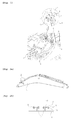
- a conventional hydraulic piping fixing device for a construction machine in accordance with the prior art shown in Fig. 1 includes:
- the hydraulic piping 3 is a metal pipe that is join-connected to a main piping (e.g., hydraulic hose) through a connector 9 mounted on an outlet side of the main piping connected at an inlet side thereof to a main control valve (MCV) 7 mounted on the upper swing structure.
- a main piping e.g., hydraulic hose
- MCV main control valve
- the conventional hydraulic piping fixing device entails a shortcoming in that since the fastening member 6 is loosened from the piping seat 2 due to vibration, and the fastening member 6 loosened due to the repeated work may escape from the piping seat 2, the device is very vulnerable to vibration. Despite the disadvantage of causing damage to the machine image due to degradation of quality by the loosening of the fastening member 6 that fastens the steel clamp 5 to the piping seat, the conventional hydraulic piping fixing device constructed as an inexpensive structure is still applied to some construction sites.
- Fig. 2(a) is a side view of a boom structure
- Fig. 2(b) is a cross-sectional view taken along the line A-A of Fig. 2(a) .
- FIG. 2(a) and 2(b) Another conventional hydraulic piping fixing device for a construction machine in accordance with the prior art shown in Figs. 2(a) and 2(b) includes:
- the conventional hydraulic piping fixing device encounters a problem in that the fastening member 12 is loosened due to vibration occurring during the quarry work or the like to cause the hydraulic piping 3 to droop in a state in which the hydraulic piping 3 is connected to the main piping 9 by means of a connector 9 and then is mounted on the upper plate of the boom structure 1.
- main piping 8 e.g., hydraulic hose
- MCV main control valve
- the hydraulic piping 3 mounted on the upper plate of the boom structure 1 are connected to each other using the connector 9 so as to be fit for a hydraulic circuit.
- the arm cylinder can be driven by a hydraulic fluid supplied from the main control valve 7 through the main piping 8 and the hydraulic piping 3.
- the fastening member 12 is gradually loosened due to vibration occurring during the quarry work and thus the fastening state of the upper clamp 11 that securely fixes the hydraulic piping 3 is also released gradually.
- the main piping 8 forcibly pulls the hydraulic piping 3 toward the upper swing structure to cause the hydraulic piping 3 to droop.
- the boom structure 1 rotatably connected to the upper swing structure by the boom fixing pin 13 is pivotally driven along a given trajectory about a boom fixing pin 13 in a vertical direction, at which time, the fastening member 12 that securely fixes the upper clamp 11 to the lower clamp 10 is loosened due to vibration to cause the clamping force of the upper clamp 11 to the lower clamp 10 to be weakened.
- the main piping 8 connected to the main control valve 7 forcibly pulls the hydraulic piping 3 securely fixed between the lower clamp 10 and the upper clamp 11 to cause the hydraulic piping 3 to droop.
- the hydraulic piping 3 is maintained in a state of being aligned in a straight line at an early stage in which the hydraulic piping 3 is securely mounted on the boom structure 1.
- the hydraulic piping 3 droops due to vibration occurring during the work, the non-matched assembly position is exposed, thereby degrading an outer appearance image of the construction machine.
- the fastening member 12 is designed to have a size larger than a reference size in order to prevent the fastening member 12 from drooping due to vibration occurring during the work.
- a separate clamp is installed in order to prevent the fastening member 12 from drooping, which leads to an increase in the number of parts, thereby deteriorating assembly workability.
- the present invention has been made to solve the aforementioned problem occurring in the prior art, and it is an object of the present invention to provide a hydraulic piping fixing device for a construction machine, in which even when bolts that fasten clamps for securely fixing the hydraulic piping to an upper plate of a boom structure are loosened due to vibration occurring during the work, the hydraulic piping can be prevented for drooping so that a coating layer formed on the outer surface of the hydraulic piping can be avoided from being peeled off.
- Another object of the present invention is to provide a hydraulic piping fixing device for a construction machine, in which the hydraulic piping can fixedly aligned easily in a straight line on the boom structure even without using a separate assembly jig.
- a hydraulic piping fixing device for a construction machine, including a piping seat weldingly fixed to a boom structure, a pair of upper and lower clamps having a fixing portion fixed onto the piping seat and arc-shaped grooves symmetrically formed on the left and right sides of the fixing portion to support hydraulic piping arranged on the boom structure, and a fastening member configured to securely fix the fixing portion of the upper and lower clamps to the piping seat, the hydraulic piping fixing device including:
- a hydraulic piping fixing device for a construction machine, including a piping seat weldingly fixed to a boom structure, a pair of upper and lower clamps having a fixing portion fixed onto the piping seat and arc-shaped grooves formed to extend from the fixing portion to support a hydraulic piping arranged on the boom structure, and a fastening member configured to securely fix the fixing portion of the upper and lower clamps to the piping seat, the hydraulic piping fixing device including:
- the hydraulic piping fixing plate may be securely fixed to the piping seat 51 by a bolt 63 that is fastened to a screw hole 51a formed on a side surface of the piping seat 51.
- the hydraulic piping fixing plate 58 may include a first fixing plate 66 mounted on the fixing portion 52 of the upper clamp 55, and a second fixing plate 67 which is curvedly formed to extend from the first fixing plate 66 and to which the bolt 63 for securely fixing the connector 62 to the hydraulic piping fixing plate 58 is fastened.
- the hydraulic piping fixing plate may be mounted on an auxiliary piping seat weldingly fixed to the boom structure.
- the nut 64 engaged with the bolt for securely fixing the connector to one surface of the hydraulic piping fixing plate may be weldingly fixed to the other surface of the hydraulic piping fixing plate.
- the bolt 63 for securely fixing the connector 62 to the hydraulic piping fixing plate 58 may be primarily fastened to a screw hole 51a that is formed on a plate-shaped connector 62a fixed to the hydraulic piping side, and may be secondarily fastened to the nut 64.
- the hydraulic piping fixing device for a construction machine in accordance with an embodiment of the present invention as constructed above has the following advantages.
- the hydraulic piping can be prevented for drooping so that a coating layer formed on the outer surface of the hydraulic piping can be avoided from being peeled off.
- the hydraulic piping can fixedly aligned easily in a straight line on the boom structure even without using a separate assembly jig, thereby improving workability.
- a hydraulic piping fixing device for a construction machine in accordance with a first embodiment of the present invention as shown in Figs. 3 to 7 includes a piping seat 51 weldingly fixed to a boom structure 50, a pair of upper and lower clamps 55 and 56 having a fixing portion 52 fixed onto the piping seat 51 and arc-shaped grooves 54 symmetrically formed on the left and right sides of the fixing portion 52 to support a hydraulic piping (e.g., hydraulic piping for an arm cylinder) 53 arranged on the boom structure 50, and a fastening member 57 configured to securely fix the fixing portion 52 of the upper and lower clamps 55 and 56 to the piping seat 51.
- a hydraulic piping e.g., hydraulic piping for an arm cylinder
- the hydraulic piping fixing device for a construction machine includes:
- the bolt 63 that securely fixes the connector 62 to the hydraulic piping fixing plate 58 is primarily fastened to a screw hole 51a that is formed on a plate-shaped connector 62a fixed to the hydraulic piping 53 side, and then is secondarily fastened to the nut 64.
- the hydraulic piping fixing plate 58 is securely fixed to the piping seat 51 by a plurality of bolts 63 that is fastened to a plurality of screw holes 51a formed on a side surface of the piping seat 51.
- the hydraulic piping fixing plate 58 includes a first fixing plate 66 mounted on the fixing portion 52 of the upper clamp 55 by the fastening member 57, and a second fixing plate 67 which is curvedly formed to extend from the first fixing plate 66 and to which the bolts 63 for securely fixing the connector 62 to the hydraulic piping fixing plate 58 are fastened.
- the configuration of the piping seat 51 weldingly fixed to a boom structure 50, and the pair of upper and lower clamps 55 and 56 having a fixing portion 52 fixed onto the piping seat 51 by the fastening member 57 and the arc-shaped grooves 54 symmetrically formed on the left and right sides of the fixing portion 52 to support the hydraulic piping 53 is the same as that of the hydraulic piping shown in Fig. 4 .
- the detailed description of the same configuration thereof will be omitted to avoid redundancy, and the same elements are denoted by the same reference numerals.
- the hydraulic piping fixing plate 58 is mounted on an auxiliary piping seat 68 weldingly fixed to the boom structure 50 by bolts 71.
- the configuration of the piping seat 51 weldingly fixed to a boom structure 50, and the pair of upper and lower clamps 55 and 56 having a fixing portion 52 fixed onto the piping seat 51 by the fastening member 57 and the arc-shaped grooves 54 symmetrically formed on the left and right sides of the fixing portion 52 to support the hydraulic piping 53 is the same as that of the hydraulic piping shown in Fig. 4 .
- the detailed description of the same configuration thereof will be omitted to avoid redundancy, and the same elements are denoted by the same reference numerals.
- the nut 64 engaged with the bolt 63 for securely fixing the connector 62 to one surface of the hydraulic piping fixing plate 58 is weldingly fixed to the other surface of the hydraulic piping fixing plate 58.
- the lower clamp 56 is seated on the piping seat 51 weldingly fixed to the boom structure 50, and the hydraulic piping 53 is seated on the grooves formed on the left and right sides of the lower clamp 56. Thereafter, the upper clamp 55 is superimposed on the lower clamp 56 and the fastening member 57 is fastened to the piping seat 51 to securely fix the hydraulic piping 53.
- plate-shaped connectors 62a respectively mounted on the hydraulic piping 53 are aligned in a straight line on the boom structure 50 (indicated by a reference symbol "a"). That is, the connectors 62a are is fixed to form a straight line using the hydraulic piping fixing plate 58 fastened to the piping seat 51 by the bolts 65.
- the hydraulic piping fixing plate 58 is securely fixed to the piping seat 51 by bolts 63 that are fastened to screw holes 51a formed on a side surface of the piping seat 51.
- the boom structure 50 is docked to the upper swing structure so as to joint-connect the main piping 60 that is at one end thereof to the main control valve 59 mounted the upper swing structure and the hydraulic piping 53 mounted on the boom structure 50.
- the connector 62b fixed to the other end of the main piping 60 and the connector 62a fixed to the hydraulic piping 53 are closely abut against with each other, and then the connector 62b and the connector 62a are fastened to each other by the bolts 61 so that the main piping 60 and the hydraulic piping 53 can be join-connected so as to fluidically communicate with each other.
- the bolts 63 (for example, two bolts are used) that securely fix the connector 62; 62a, 62b to one surface of the hydraulic piping fixing plate 58 are required to have a sufficient length enough to pass through the main piping-side connector 62b, the hydraulic piping-side connector 62a, and the hydraulic piping fixing plate 58 in this order and then to be fastened to the nuts 64 on the other surface of the hydraulic piping fixing plate 58.
- the connectors 62b and 62a weldingly fixed to the main piping 60 and the hydraulic piping 53, respectively, are fixed to the hydraulic piping fixing plate 58 by the bolts 63, so that even if the fastening member 57 that securely fixes the upper and lower clamps 55 and 56 to the piping seat 51 to support the hydraulic piping 53 is loosened due to vibration occurring during the quarry work or the like, the hydraulic piping 53 supported by the upper and lower clamps 55 and 56 can be prevented from drooping.
- the connector 62b weldingly fixed to the main piping 60 and the connector 62a weldingly fixed to the hydraulic piping 53 are closely abut against each other and then are coupled to each other by bolts 61.
- These connectors 62; 62a,62b are fastened to the hydraulic piping fixing plate 58 by the bolts 63 passing therethrough.
- the boom structure 50 is pivotally rotated about a boom fixing pin 73 in a vertical direction while forming a given trajectory, so that even when the main piping 60 pulls the hydraulic piping 53 toward the upper swing structure, the connector 62a fixed to the hydraulic piping 53 can be maintained in a state of being fixed to the hydraulic piping fixing plate 58 by the bolts 63, thereby preventing the hydraulic piping 53 from drooping.
- the bolts 63 are primarily screwed to screw holes formed on the connector 62a fixed to the hydraulic piping 53 and then are secondarily fastened to nuts 64 positioned on the other surface of the hydraulic piping fixing plate 58 after passing through through-holes of the hydraulic piping fixing plate 58.
- the fastening force by which the connector 62a fixed to the hydraulic piping 53 is securely fixed to the hydraulic piping fixing plate 58 is maintained semipermanently so that the hydraulic piping 53 is prevented from drooping.
- a hydraulic piping fixing device for a construction machine in accordance with a second embodiment of the present invention as shown in Figs. 8 to 10 includes a piping seat 51 weldingly fixed to a boom structure 50, a pair of upper and lower clamps 69 and 70 having a fixing portion 72 fixed onto the piping seat 51 and arc-shaped grooves 74 formed to extend from one side of the fixing portion 72 to support a hydraulic piping 53 arranged on the boom structure 50, and a fastening member 57 configured to securely fix the fixing portion 72 of the upper and lower clamps 69 and 70 to the piping seat 51.
- the hydraulic piping fixing device for a construction machine includes: a hydraulic piping fixing plate 58 that is mounted on the piping seat 51; a connector 62 (62a; a connector on a hydraulic piping 53 side/62b: a connector on a main piping 60 side) that is weldingly fixed to an end of a main piping (e.g.
- hydraulic hose 60 that is connected to the main control valve (MCV) 59 mounted on an upper swing structure and an end of the hydraulic piping (e.g., metal pipe) 53 that is arranged on the boom structure 50, respectively, and joint-connects the fixed ends of the main piping and the hydraulic piping through the fastening of a bolt 61; and a bolt 63 and a nut 64 that securely fix the connector 62 to the hydraulic piping fixing plate 58, whereby when the fastening member 57 is loosened due to vibration occurring during the work, the hydraulic piping 53 is prevented from drooping by the connector 62 fixed to the hydraulic piping fixing plate 58.
- MCV main control valve
- the detailed description of the same configuration thereof will be omitted to avoid redundancy, and the same elements are denoted by the same reference numerals.
- the lower clamp 70 is seated on the piping seat 51 weldingly fixed to the boom structure 50, and the hydraulic piping 53 is seated on the grooves formed to extend from one side of the fixing portion 72. Thereafter, the upper clamp 69 is superimposed on the lower clamp 70 and the fastening member 57 is fastened to the piping seat 51 to securely fix the hydraulic piping 53.
- the hydraulic piping fixing device for a construction machine in accordance with an embodiment of the present invention, even when the bolts that fasten the clamps for securely fixing the hydraulic piping to the upper plate of the boom structure are loosened due to vibration occurring during the work, the hydraulic piping can be prevented for drooping by securely fixing a flange of the hydraulic piping to the hydraulic piping fixing plate fixed to the piping seat using a separate bolt.
- the hydraulic piping can fixedly aligned in a straight line on the boom structure even without using a separate assembly jig.
Landscapes
- Engineering & Computer Science (AREA)
- General Engineering & Computer Science (AREA)
- Mining & Mineral Resources (AREA)
- Civil Engineering (AREA)
- Structural Engineering (AREA)
- Mechanical Engineering (AREA)
- Supports For Pipes And Cables (AREA)
- Shovels (AREA)
- Component Parts Of Construction Machinery (AREA)
Abstract
Description
- The present invention relates to a hydraulic piping fixing device for a construction machine. More particularly, the present invention relates to a hydraulic piping fixing device for a construction machine, in which even when bolts that fasten the clamps for securely fixing the hydraulic piping (e.g., hydraulic piping for an arm cylinder) to the upper plate of the boom structure is loosened due to vibration occurring during the work (e. g. , quarry work, breaker work or the like), the hydraulic piping can be prevented for drooping.
- A conventional hydraulic piping fixing device for a construction machine in accordance with the prior art shown in
Fig. 1 includes: - a
piping seat 2 weldingly fixed to an upper plate of a boom structure 1 such as an excavator; - a hydraulic piping 3 (e.g., hydraulic piping for an arm cylinder) seated on the
piping seat 2; - a
steel clamp 5 having semi-circular shaped seating grooves formed therein to support thehydraulic piping 3; and - a fastening
member 6 configured to fasten thesteel clamp 5 to thepiping seat 2 to allow thehydraulic piping 3 to be securely fixed by thesteel clamp 5 and thepiping seat 2. - In this case, the
hydraulic piping 3 is a metal pipe that is join-connected to a main piping (e.g., hydraulic hose) through a connector 9 mounted on an outlet side of the main piping connected at an inlet side thereof to a main control valve (MCV) 7 mounted on the upper swing structure. - As described above, if a quarry work or breaker work is performed in a state in which the
hydraulic piping 3 is securely fixed to the boom structure, since vibration occurring due to an external shock is directly transferred to thehydraulic piping 3 and thesteel clamp 5, leakage of hydraulic fluid occurs through a crack formed on thehydraulic piping 3 due to frequent vibration. - Meanwhile, the conventional hydraulic piping fixing device entails a shortcoming in that since the
fastening member 6 is loosened from thepiping seat 2 due to vibration, and the fasteningmember 6 loosened due to the repeated work may escape from thepiping seat 2, the device is very vulnerable to vibration. Despite the disadvantage of causing damage to the machine image due to degradation of quality by the loosening of thefastening member 6 that fastens thesteel clamp 5 to the piping seat, the conventional hydraulic piping fixing device constructed as an inexpensive structure is still applied to some construction sites. -
Fig. 2(a) is a side view of a boom structure, andFig. 2(b) is a cross-sectional view taken along the line A-A ofFig. 2(a) . - Another conventional hydraulic piping fixing device for a construction machine in accordance with the prior art shown in
Figs. 2(a) and 2(b) includes: - a
piping seat 2 weldingly fixed to an upper plate of a boom structure 1 of an excavator; - a
lower clamp 10 seated on thepiping seat 2; - a hydraulic piping 3 (e.g. , hydraulic piping for an arm cylinder) seated on seating grooves symmetrically formed on the left and right sides of the
lower clamp 10; - an
upper claim 11 configured to securely fix thehydraulic piping 3 seated on thelower clamp 10; and - a fastening
member 12 configured to fasten theupper clamp 11 to thelower clamp 10 to allow thehydraulic piping 3 to be securely seated on the seating grooves of the upper andlower clamps - Thus, since the
hydraulic piping 3 is securely fixed in a state of being not brought into direct contact with thepiping seat 2, a problem associated with occurrence of vibration during the work can be overcome. - In the meantime, the conventional hydraulic piping fixing device encounters a problem in that the
fastening member 12 is loosened due to vibration occurring during the quarry work or the like to cause thehydraulic piping 3 to droop in a state in which thehydraulic piping 3 is connected to the main piping 9 by means of a connector 9 and then is mounted on the upper plate of the boom structure 1. - More specifically, the main piping 8 (e.g., hydraulic hose) connected to the main control valve (MCV) mounted on the upper swing structure of the excavator and the
hydraulic piping 3 mounted on the upper plate of the boom structure 1 are connected to each other using the connector 9 so as to be fit for a hydraulic circuit. Thus, the arm cylinder can be driven by a hydraulic fluid supplied from the main control valve 7 through the main piping 8 and thehydraulic piping 3. - In this case, the fastening
member 12 is gradually loosened due to vibration occurring during the quarry work and thus the fastening state of theupper clamp 11 that securely fixes thehydraulic piping 3 is also released gradually. Thus, the main piping 8 forcibly pulls thehydraulic piping 3 toward the upper swing structure to cause thehydraulic piping 3 to droop. - The reason for this is that the boom structure 1 rotatably connected to the upper swing structure by the
boom fixing pin 13 is pivotally driven along a given trajectory about aboom fixing pin 13 in a vertical direction, at which time, the fasteningmember 12 that securely fixes theupper clamp 11 to thelower clamp 10 is loosened due to vibration to cause the clamping force of theupper clamp 11 to thelower clamp 10 to be weakened. - For this reason, the main piping 8 connected to the main control valve 7 forcibly pulls the
hydraulic piping 3 securely fixed between thelower clamp 10 and theupper clamp 11 to cause thehydraulic piping 3 to droop. - As described above, the
hydraulic piping 3 is maintained in a state of being aligned in a straight line at an early stage in which thehydraulic piping 3 is securely mounted on the boom structure 1. However, there is caused a problem in that when thehydraulic piping 3 droops due to vibration occurring during the work, the non-matched assembly position is exposed, thereby degrading an outer appearance image of the construction machine. - For this reason, the fastening
member 12 is designed to have a size larger than a reference size in order to prevent the fasteningmember 12 from drooping due to vibration occurring during the work. Alternatively, a separate clamp is installed in order to prevent thefastening member 12 from drooping, which leads to an increase in the number of parts, thereby deteriorating assembly workability. - Accordingly, the present invention has been made to solve the aforementioned problem occurring in the prior art, and it is an object of the present invention to provide a hydraulic piping fixing device for a construction machine, in which even when bolts that fasten clamps for securely fixing the hydraulic piping to an upper plate of a boom structure are loosened due to vibration occurring during the work, the hydraulic piping can be prevented for drooping so that a coating layer formed on the outer surface of the hydraulic piping can be avoided from being peeled off.
- Another object of the present invention is to provide a hydraulic piping fixing device for a construction machine, in which the hydraulic piping can fixedly aligned easily in a straight line on the boom structure even without using a separate assembly jig.
- To accomplish the above object, in accordance with a first embodiment of the present invention, there is provided a hydraulic piping fixing device for a construction machine, including a piping seat weldingly fixed to a boom structure, a pair of upper and lower clamps having a fixing portion fixed onto the piping seat and arc-shaped grooves symmetrically formed on the left and right sides of the fixing portion to support hydraulic piping arranged on the boom structure, and a fastening member configured to securely fix the fixing portion of the upper and lower clamps to the piping seat, the hydraulic piping fixing device including:
- a hydraulic piping fixing plate mounted on the piping seat;
- a connector configured to joint-connect a main piping that is connected to a main control valve mounted on an upper swing structure and a hydraulic piping that is arranged on the boom structure; and
- a bolt and a nut configured to securely fix the connector to the hydraulic piping fixing plate;
- whereby when the fastening member is loosened due to vibration occurring during the work, the hydraulic piping are prevented from drooping by the connector fixed to the hydraulic piping fixing plate.
- In accordance with a second embodiment of the present invention, there is provided a hydraulic piping fixing device for a construction machine, including a piping seat weldingly fixed to a boom structure, a pair of upper and lower clamps having a fixing portion fixed onto the piping seat and arc-shaped grooves formed to extend from the fixing portion to support a hydraulic piping arranged on the boom structure, and a fastening member configured to securely fix the fixing portion of the upper and lower clamps to the piping seat, the hydraulic piping fixing device including:
- a hydraulic piping fixing plate mounted on the piping seat;
- a connector configured to joint-connect a main piping that is connected to a main control valve mounted on an upper swing structure and a hydraulic piping that is arranged on the boom structure; and
- a bolt and a nut configured to securely fix the connector to the hydraulic piping fixing plate
- whereby when the fastening member is loosened due to vibration occurring during the work, the hydraulic piping are prevented from drooping by the connector fixed to the hydraulic piping fixing plate.
- In accordance with a preferred embodiment of the present invention, the hydraulic piping fixing plate may be securely fixed to the
piping seat 51 by abolt 63 that is fastened to ascrew hole 51a formed on a side surface of thepiping seat 51. - The hydraulic
piping fixing plate 58 may include afirst fixing plate 66 mounted on thefixing portion 52 of theupper clamp 55, and asecond fixing plate 67 which is curvedly formed to extend from thefirst fixing plate 66 and to which thebolt 63 for securely fixing theconnector 62 to the hydraulicpiping fixing plate 58 is fastened. - The hydraulic piping fixing plate may be mounted on an auxiliary piping seat weldingly fixed to the boom structure.
- The
nut 64 engaged with the bolt for securely fixing the connector to one surface of the hydraulic piping fixing plate may be weldingly fixed to the other surface of the hydraulic piping fixing plate. - The
bolt 63 for securely fixing theconnector 62 to the hydraulicpiping fixing plate 58 may be primarily fastened to ascrew hole 51a that is formed on a plate-shaped connector 62a fixed to the hydraulic piping side, and may be secondarily fastened to thenut 64. - The hydraulic piping fixing device for a construction machine in accordance with an embodiment of the present invention as constructed above has the following advantages.
- Even when bolts that fasten the clamps for securely fixing the hydraulic piping to the upper plate of the boom structure are loosened due to vibration occurring during the work, the hydraulic piping can be prevented for drooping so that a coating layer formed on the outer surface of the hydraulic piping can be avoided from being peeled off. In addition, the hydraulic piping can fixedly aligned easily in a straight line on the boom structure even without using a separate assembly jig, thereby improving workability.
- The above objects, other features and advantages of the present invention will become more apparent by describing the preferred embodiments thereof with reference to the accompanying drawings, in which:
-
Fig. 1 is a schematic view showing a conventional hydraulic piping fixing device for a construction machine in accordance with the prior art; -
Figs. 2(a) and 2(b) are another conventional hydraulic piping fixing device for a construction machine in accordance with the prior art; -
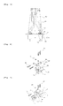
Fig. 3 is a schematic view showing a use state of a hydraulic piping fixing device for a construction machine in accordance with a first embodiment of the present invention; -
Fig. 4 is an exploded perspective view showing main elements of a hydraulic piping fixing device for a construction machine in accordance with a first embodiment of the present invention; -
Fig. 5 is an exploded perspective view showing a state in which the hydraulic piping is fixedly aligned in a straight line on a boom structure in a hydraulic piping fixing device for a construction machine in accordance with a first embodiment of the present invention; -
Fig. 6 is an exploded perspective view showing a modification of a hydraulic piping fixing device for a construction machine in accordance with a first embodiment of the present invention; -
Fig. 7 is an exploded perspective view showing another modification of a hydraulic piping fixing device for a construction machine in accordance with a first embodiment of the present invention; -
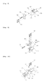
Fig. 8 is an exploded perspective view showing main elements of a hydraulic piping fixing device for a construction machine in accordance with a second embodiment of the present invention; -
Fig. 9 is an exploded perspective view showing a modification of a hydraulic piping fixing device for a construction machine in accordance with a second embodiment of the present invention; and -
Fig. 10 is an exploded perspective view showing another modification of a hydraulic piping fixing device for a construction machine in accordance with a second embodiment of the present invention. -
- 50:
- first rubber pad
- 50;
- boom structure
- 52;
- fixing portion
- 54;
- groove
- 56;
- lower clamp
- 58;
- hydraulic piping fixing plate
- 60;
- main piping
- 62;
- connector
- 64;
- nut
- 66;
- first fixing plate
- 68;
- auxiliary piping seat
- 70;
- lower clamp
- 72;
- fixing portion
- Now, preferred embodiments of the present invention will be described in detail with reference to the accompanying drawings. The matters defined in the description, such as the detailed construction and elements, are nothing but specific details provided to assist those of ordinary skill in the art in a comprehensive understanding of the invention, and the present invention is not limited to the embodiments disclosed hereinafter.
- A hydraulic piping fixing device for a construction machine in accordance with a first embodiment of the present invention as shown in
Figs. 3 to 7 includes a pipingseat 51 weldingly fixed to aboom structure 50, a pair of upper andlower clamps portion 52 fixed onto the pipingseat 51 and arc-shapedgrooves 54 symmetrically formed on the left and right sides of the fixingportion 52 to support a hydraulic piping (e.g., hydraulic piping for an arm cylinder) 53 arranged on theboom structure 50, and afastening member 57 configured to securely fix the fixingportion 52 of the upper andlower clamps seat 51. - The hydraulic piping fixing device for a construction machine includes:
- a hydraulic
piping fixing plate 58 that is mounted on the pipingseat 51; - a connector 62 (62a; a connector on a
hydraulic piping 53 side/62b: a connector on amain piping 60 side) that is weldingly fixed to an end of a main piping (e.g., hydraulic hose) 60 that is connected to the main control valve (MCV) 59 mounted on an upper swing structure and an end of the hydraulic piping (e.g., metal pipe) 53 that is arranged on theboom structure 50, respectively, and joint-connects the fixed ends of the main piping and the hydraulic piping through the fastening of abolt 61; and - a
bolt 63 and anut 64 that securely fix theconnector 62 to the hydraulicpiping fixing plate 58, - whereby when the
fastening member 57 is loosened due to vibration occurring during the work, thehydraulic piping 53 is prevented from drooping by theconnector 62 fixed to the hydraulicpiping fixing plate 58. - As shown in
Fig. 3 , thebolt 63 that securely fixes theconnector 62 to the hydraulicpiping fixing plate 58 is primarily fastened to ascrew hole 51a that is formed on a plate-shapedconnector 62a fixed to thehydraulic piping 53 side, and then is secondarily fastened to thenut 64. - As shown in
Fig. 4 , the hydraulicpiping fixing plate 58 is securely fixed to the pipingseat 51 by a plurality ofbolts 63 that is fastened to a plurality ofscrew holes 51a formed on a side surface of the pipingseat 51. - As shown in
Fig. 6 , the hydraulicpiping fixing plate 58 includes afirst fixing plate 66 mounted on the fixingportion 52 of theupper clamp 55 by thefastening member 57, and asecond fixing plate 67 which is curvedly formed to extend from thefirst fixing plate 66 and to which thebolts 63 for securely fixing theconnector 62 to the hydraulicpiping fixing plate 58 are fastened. - In this case, the configuration of the piping
seat 51 weldingly fixed to aboom structure 50, and the pair of upper andlower clamps portion 52 fixed onto the pipingseat 51 by thefastening member 57 and the arc-shapedgrooves 54 symmetrically formed on the left and right sides of the fixingportion 52 to support thehydraulic piping 53 is the same as that of the hydraulic piping shown inFig. 4 . Thus, the detailed description of the same configuration thereof will be omitted to avoid redundancy, and the same elements are denoted by the same reference numerals. - As shown in
Fig. 7 , the hydraulicpiping fixing plate 58 is mounted on anauxiliary piping seat 68 weldingly fixed to theboom structure 50 bybolts 71. - In this case, the configuration of the piping
seat 51 weldingly fixed to aboom structure 50, and the pair of upper andlower clamps portion 52 fixed onto the pipingseat 51 by thefastening member 57 and the arc-shapedgrooves 54 symmetrically formed on the left and right sides of the fixingportion 52 to support thehydraulic piping 53 is the same as that of the hydraulic piping shown inFig. 4 . Thus, the detailed description of the same configuration thereof will be omitted to avoid redundancy, and the same elements are denoted by the same reference numerals. - Although not shown in the drawings, the
nut 64 engaged with thebolt 63 for securely fixing theconnector 62 to one surface of the hydraulicpiping fixing plate 58 is weldingly fixed to the other surface of the hydraulicpiping fixing plate 58. - Hereinafter, a use example of the hydraulic piping fixing device for a construction machine in accordance with a first embodiment of the present invention will be described in detail with reference to the accompanying drawings.
- As shown in
Figs. 3 to 5 , thelower clamp 56 is seated on the pipingseat 51 weldingly fixed to theboom structure 50, and thehydraulic piping 53 is seated on the grooves formed on the left and right sides of thelower clamp 56. Thereafter, theupper clamp 55 is superimposed on thelower clamp 56 and thefastening member 57 is fastened to the pipingseat 51 to securely fix thehydraulic piping 53. - In this case, as shown in
Fig. 5 , plate-shapedconnectors 62a respectively mounted on thehydraulic piping 53 are aligned in a straight line on the boom structure 50 (indicated by a reference symbol "a"). That is, theconnectors 62a are is fixed to form a straight line using the hydraulicpiping fixing plate 58 fastened to the pipingseat 51 by thebolts 65. - Hereinafter, a process of fixing the
hydraulic piping 53 using the hydraulicpiping fixing plate 58 fixed to the pipingseat 51 will be described in detail. - As shown in
Figs. 3 to 5 , the hydraulicpiping fixing plate 58 is securely fixed to the pipingseat 51 bybolts 63 that are fastened to screwholes 51a formed on a side surface of the pipingseat 51. In this case, theboom structure 50 is docked to the upper swing structure so as to joint-connect themain piping 60 that is at one end thereof to themain control valve 59 mounted the upper swing structure and thehydraulic piping 53 mounted on theboom structure 50. Thereafter, theconnector 62b fixed to the other end of themain piping 60 and theconnector 62a fixed to thehydraulic piping 53 are closely abut against with each other, and then theconnector 62b and theconnector 62a are fastened to each other by thebolts 61 so that themain piping 60 and thehydraulic piping 53 can be join-connected so as to fluidically communicate with each other. - In the meantime, the bolts 63 (for example, two bolts are used) that securely fix the
connector 62; 62a, 62b to one surface of the hydraulicpiping fixing plate 58 are required to have a sufficient length enough to pass through the main piping-side connector 62b, the hydraulic piping-side connector 62a, and the hydraulicpiping fixing plate 58 in this order and then to be fastened to the nuts 64 on the other surface of the hydraulicpiping fixing plate 58. - As described above, the
connectors main piping 60 and thehydraulic piping 53, respectively, are fixed to the hydraulicpiping fixing plate 58 by thebolts 63, so that even if thefastening member 57 that securely fixes the upper andlower clamps seat 51 to support thehydraulic piping 53 is loosened due to vibration occurring during the quarry work or the like, thehydraulic piping 53 supported by the upper andlower clamps - That is, the
connector 62b weldingly fixed to themain piping 60 and theconnector 62a weldingly fixed to thehydraulic piping 53 are closely abut against each other and then are coupled to each other bybolts 61. Theseconnectors 62; 62a,62b are fastened to the hydraulicpiping fixing plate 58 by thebolts 63 passing therethrough. - For this reason, if the
fastening member 57 by which the upper andlower clamps seat 51 is loosened due to vibration occurring during the work to cause a fastening force of the upper andlower clamps boom structure 50 is pivotally rotated about aboom fixing pin 73 in a vertical direction while forming a given trajectory, so that even when themain piping 60 pulls thehydraulic piping 53 toward the upper swing structure, theconnector 62a fixed to thehydraulic piping 53 can be maintained in a state of being fixed to the hydraulicpiping fixing plate 58 by thebolts 63, thereby preventing the hydraulic piping 53 from drooping. - In this case, the
bolts 63 are primarily screwed to screw holes formed on theconnector 62a fixed to thehydraulic piping 53 and then are secondarily fastened tonuts 64 positioned on the other surface of the hydraulicpiping fixing plate 58 after passing through through-holes of the hydraulicpiping fixing plate 58. Thus, the fastening force by which theconnector 62a fixed to thehydraulic piping 53 is securely fixed to the hydraulicpiping fixing plate 58 is maintained semipermanently so that thehydraulic piping 53 is prevented from drooping. For this reason, when thehydraulic piping 53 droops, it can be prevented that a coating layer formed on thehydraulic piping 53 is peeled off or the assembled position of thehydraulic piping 53 with respect to theboom structure 50 is not uniform to cause an outer appearance image to be degraded. In the meantime, when theconnector 62 that join-connects thehydraulic piping 53 and themain piping 60 is securely fixed to theboom structure 50, it can be fixedly aligned in a straight line on relative to the hydraulicpiping fixing plate 58 fixed to the pipingseat 51 without using a separate jig. - A hydraulic piping fixing device for a construction machine in accordance with a second embodiment of the present invention as shown in
Figs. 8 to 10 includes a pipingseat 51 weldingly fixed to aboom structure 50, a pair of upper andlower clamps portion 72 fixed onto the pipingseat 51 and arc-shapedgrooves 74 formed to extend from one side of the fixingportion 72 to support ahydraulic piping 53 arranged on theboom structure 50, and afastening member 57 configured to securely fix the fixingportion 72 of the upper andlower clamps seat 51. - The hydraulic piping fixing device for a construction machine includes: a hydraulic
piping fixing plate 58 that is mounted on the pipingseat 51;
a connector 62 (62a; a connector on ahydraulic piping 53 side/62b: a connector on amain piping 60 side) that is weldingly fixed to an end of a main piping (e.g. , hydraulic hose) 60 that is connected to the main control valve (MCV) 59 mounted on an upper swing structure and an end of the hydraulic piping (e.g., metal pipe) 53 that is arranged on theboom structure 50, respectively, and joint-connects the fixed ends of the main piping and the hydraulic piping through the fastening of abolt 61; and
abolt 63 and anut 64 that securely fix theconnector 62 to the hydraulicpiping fixing plate 58,
whereby when thefastening member 57 is loosened due to vibration occurring during the work, thehydraulic piping 53 is prevented from drooping by theconnector 62 fixed to the hydraulicpiping fixing plate 58. - In this case, the configuration of the hydraulic
piping fixing plate 58 mounted on the pipingseat 51, theconnector 62 that joint-connects themain piping 60 mounted on theupper swing structure 50 and thehydraulic piping 53 arranged on theboom structure 50, and thebolt 63 that securely fixes theconnector 62 to the hydraulicpiping fixing plate 58 so that even when thefastening member 57 that securely fixes the upper andlower clamps seat 51 to support thehydraulic piping 53 is loosened due to vibration occurring during the work, thehydraulic piping 53 is prevented from drooping by the hydraulicpiping fixing plate 58 is the same that of the hydraulic piping fixing device in accordance with the first embodiment of the present invention. Thus, the detailed description of the same configuration thereof will be omitted to avoid redundancy, and the same elements are denoted by the same reference numerals. - Hereinafter, a use example of the hydraulic piping fixing device for a construction machine in accordance with a second embodiment of the present invention will be described in detail with reference to the accompanying drawings.
- As shown in
Figs. 8 to 10 , thelower clamp 70 is seated on the pipingseat 51 weldingly fixed to theboom structure 50, and thehydraulic piping 53 is seated on the grooves formed to extend from one side of the fixingportion 72. Thereafter, theupper clamp 69 is superimposed on thelower clamp 70 and thefastening member 57 is fastened to the pipingseat 51 to securely fix thehydraulic piping 53. - As described above, since the
hydraulic piping 53 supported by the upper andlower clamps seat 51, vibration occurring during the work can be prevented from being directly transferred to thehydraulic piping 53 and the upper andlower clamps - While the present invention has been described in connection with the specific embodiments illustrated in the drawings, they are merely illustrative, and the invention is not limited to these embodiments. It is to be understood that various equivalent modifications and variations of the embodiments can be made by a person having an ordinary skill in the art without departing from the spirit and scope of the present invention. Therefore, the true technical scope of the present invention should not be defined by the above-mentioned embodiments but should be defined by the appended claims and equivalents thereof.
- As described above, according to the hydraulic piping fixing device for a construction machine in accordance with an embodiment of the present invention, even when the bolts that fasten the clamps for securely fixing the hydraulic piping to the upper plate of the boom structure are loosened due to vibration occurring during the work, the hydraulic piping can be prevented for drooping by securely fixing a flange of the hydraulic piping to the hydraulic piping fixing plate fixed to the piping seat using a separate bolt. In addition, the hydraulic piping can fixedly aligned in a straight line on the boom structure even without using a separate assembly jig.
Claims (12)
- A hydraulic piping fixing device for a construction machine, including a piping seat weldingly fixed to a boom structure, a pair of upper and lower clamps having a fixing portion fixed onto the piping seat and arc-shaped grooves symmetrically formed on the left and right sides of the fixing portion to support hydraulic piping arranged on the boom structure, and a fastening member configured to securely fix the fixing portion of the upper and lower clamps to the piping seat, the hydraulic piping fixing device comprising:a hydraulic piping fixing plate 58 mounted on the piping seat 51;a connector configured to joint-connect a main piping that is connected to a main control valve mounted on an upper swing structure and a hydraulic piping that is arranged on the boom structure; anda bolt and a nut configured to securely fix the connector 62 to the hydraulic piping fixing plate;whereby when the fastening member is loosened due to vibration occurring during the work, the hydraulic piping are prevented from drooping by the connector fixed to the hydraulic piping fixing plate.
- A hydraulic piping fixing device for a construction machine, including a piping seat weldingly fixed to a boom structure, a pair of upper and lower clamps having a fixing portion fixed onto the piping seat and arc-shaped grooves formed to extend from the fixing portion to support a hydraulic piping arranged on the boom structure, and a fastening member configured to securely fix the fixing portion of the upper and lower clamps to the piping seat, the hydraulic piping fixing device comprising:a hydraulic piping fixing plate mounted on the piping seat;a connector configured to joint-connect a main piping that is connected to a main control valve mounted on an upper swing structure and a hydraulic piping that is arranged on the boom structure; anda bolt and a nut configured to securely fix the connector to the hydraulic piping fixing plate;whereby when the fastening member is loosened due to vibration occurring during the work, the hydraulic piping are prevented from drooping by the connector fixed to the hydraulic piping fixing plate.
- The hydraulic piping fixing device for a construction machine according to claim 1, wherein the hydraulic piping fixing plate is securely fixed to the piping seat by a bolt that is fastened to a screw hole formed on a side surface of the piping seat.
- The hydraulic piping fixing device for a construction machine according to claim 1, wherein the hydraulic piping fixing plate comprises a first fixing plate mounted on the fixing portion of the upper clamp, and a second fixing plate which is curvedly formed to extend from the first fixing plate and to which the bolt for securely fixing the connector to the hydraulic piping fixing plate is fastened.
- The hydraulic piping fixing device for a construction machine according to claim 1, wherein the hydraulic piping fixing plate is mounted on an auxiliary piping seat weldingly fixed to the boom structure.
- The hydraulic piping fixing device for a construction machine according to claim 1, wherein the nut engaged with the bolt for securely fixing the connector to one surface of the hydraulic piping fixing plate is weldingly fixed to the other surface of the hydraulic piping fixing plate.
- The hydraulic piping fixing device for a construction machine according to claim 2, wherein the hydraulic piping fixing plate is securely fixed to the piping seat by a bolt that is fastened to a screw hole formed on a side surface of the piping seat.
- The hydraulic piping fixing device for a construction machine according to claim 2, wherein the hydraulic piping fixing plate comprises a first fixing plate mounted on the fixing portion of the upper clamp, and a second fixing plate which is curvedly formed to extend from the first fixing plate 66 and to which the bolt for securely fixing the connector to the hydraulic piping fixing plate is fastened.
- The hydraulic piping fixing device for a construction machine according to claim 2, wherein the hydraulic piping fixing plate is mounted on an auxiliary piping seat weldingly fixed to the boom structure.
- The hydraulic piping fixing device for a construction machine according to claim 2, wherein the nut engaged with the bolt for securely fixing the connector to one surface of the hydraulic piping fixing plate is weldingly fixed to the other surface of the hydraulic piping fixing plate.
- The hydraulic piping fixing device for a construction machine according to claim 1, wherein the bolt for securely fixing the connector to the hydraulic piping fixing plate is primarily fastened to a screw hole that is formed on a plate-shaped connector fixed to the hydraulic piping side, and then is secondarily fastened to the nut.
- The hydraulic piping fixing device for a construction machine according to claim 2, wherein the bolt for securely fixing the connector to the hydraulic piping fixing plate is primarily fastened to a screw hole that is formed on a plate-shaped connector fixed to the hydraulic piping side, and then is secondarily fastened to the nut.
Applications Claiming Priority (1)
| Application Number | Priority Date | Filing Date | Title |
|---|---|---|---|
| PCT/KR2011/007696 WO2013058413A1 (en) | 2011-10-17 | 2011-10-17 | Device for fixing the hydraulic piping of construction equipment |
Publications (2)
| Publication Number | Publication Date |
|---|---|
| EP2770118A1 true EP2770118A1 (en) | 2014-08-27 |
| EP2770118A4 EP2770118A4 (en) | 2015-06-03 |
Family
ID=48141052
Family Applications (1)
| Application Number | Title | Priority Date | Filing Date |
|---|---|---|---|
| EP11874258.4A Withdrawn EP2770118A4 (en) | 2011-10-17 | 2011-10-17 | DEVICE FOR ATTACHING THE HYDRAULIC PIPING OF CONSTRUCTION EQUIPMENT |
Country Status (6)
| Country | Link |
|---|---|
| US (1) | US9255383B2 (en) |
| EP (1) | EP2770118A4 (en) |
| JP (1) | JP5856683B2 (en) |
| KR (1) | KR20140091672A (en) |
| CN (1) | CN103890278A (en) |
| WO (1) | WO2013058413A1 (en) |
Cited By (1)
| Publication number | Priority date | Publication date | Assignee | Title |
|---|---|---|---|---|
| CN104930266A (en) * | 2015-06-10 | 2015-09-23 | 安徽江淮汽车股份有限公司 | Air conditioner refrigeration pipeline fixing pipe clamp structure |
Families Citing this family (12)
| Publication number | Priority date | Publication date | Assignee | Title |
|---|---|---|---|---|
| JP5403013B2 (en) * | 2011-08-24 | 2014-01-29 | コベルコ建機株式会社 | Piping mounting structure for work machines |
| WO2013081212A1 (en) * | 2011-11-30 | 2013-06-06 | 볼보 컨스트럭션 이큅먼트 에이비 | Hydraulic line fixing apparatus for boom swing-type excavators |
| EP2955393A1 (en) * | 2014-06-13 | 2015-12-16 | Siemens Aktiengesellschaft | Connection clamp with metal wire mat as damping element |
| JP6345087B2 (en) * | 2014-11-14 | 2018-06-20 | Kyb−Ys株式会社 | Equipment mounting structure |
| KR20170000956U (en) * | 2015-09-04 | 2017-03-14 | 현대중공업 주식회사 | Rubber Clamp for Hydraulic Pipe in Construction Equipment |
| JP6350564B2 (en) * | 2016-03-01 | 2018-07-04 | コベルコ建機株式会社 | Valve arrangement structure for construction machinery |
| CN106194906B (en) * | 2016-08-30 | 2017-11-03 | 九方泰禾国际重工(青岛)股份有限公司 | Self propelled harvester tool hydraulic pressure four-wheel drive hydraulic oil pipe |
| US20200149662A1 (en) * | 2017-03-17 | 2020-05-14 | Meggitt Safety Systems, Inc. | High temperature clamps and methods of making the same |
| CN108978745B (en) * | 2018-09-28 | 2021-05-28 | 景冲 | An excavator with stable oil path |
| DE102021126429A1 (en) * | 2021-10-12 | 2023-04-13 | Witzenmann Gmbh | Method for fluid-conducting connection of function modules that are temperature-controlled by means of a fluid, correspondingly temperature-controlled function modules and associated connection device |
| US12428800B2 (en) * | 2022-07-22 | 2025-09-30 | Caterpillar Inc. | Apparatus to secure angle of hydraulic coupling connections |
| CN118561147B (en) * | 2024-08-01 | 2024-10-18 | 济宁鲁南公路工程公司 | Prefabricated pipe positioning and installing construction equipment |
Family Cites Families (16)
| Publication number | Priority date | Publication date | Assignee | Title |
|---|---|---|---|---|
| JPS5638313Y2 (en) * | 1976-07-07 | 1981-09-07 | ||
| JPH0137633B2 (en) * | 1979-07-16 | 1989-08-08 | Caterpillar Mitsubishi Ltd | |
| WO1982000844A1 (en) * | 1979-07-16 | 1982-03-18 | T Mueller | Guard structure for fluid conduits of hydraulic cylinders of mobile apparatus |
| JPH0731963U (en) * | 1993-11-16 | 1995-06-16 | 株式会社小松製作所 | Mounting structure of hydraulically operated valve |
| JPH08311925A (en) * | 1995-05-17 | 1996-11-26 | Hitachi Constr Mach Co Ltd | Pipe fixing / protection device |
| JP3785027B2 (en) * | 2000-06-28 | 2006-06-14 | 日立建機株式会社 | Hose connection device used for construction machinery |
| JP2002327453A (en) * | 2001-05-07 | 2002-11-15 | Komatsu Ltd | Hydraulic piping clamp device for construction machine working machine |
| JP2004137676A (en) * | 2002-10-15 | 2004-05-13 | Hitachi Constr Mach Co Ltd | Greasing pipe fitting structure and construction machine having it |
| US6883761B2 (en) * | 2003-02-13 | 2005-04-26 | General Electric Company | Support for tubular members |
| US8523120B2 (en) * | 2004-06-14 | 2013-09-03 | Komatsu Ltd. | Component support device and construction machine with component attached via the same |
| EP2012060A1 (en) * | 2007-07-03 | 2009-01-07 | Siemens Aktiengesellschaft | Three-point anchorage of ignition electrodes of a burner |
| US20090084454A1 (en) * | 2007-10-01 | 2009-04-02 | Volvo Construction Equipment Holding Sweden Ab. | Apparatus for fixing hydraulic pipes for zero tail swing excavator |
| KR101121706B1 (en) * | 2009-10-26 | 2012-03-09 | 볼보 컨스트럭션 이큅먼트 에이비 | fixing device of hydraulic pipe of construction equipment |
| JP5602944B2 (en) | 2010-05-17 | 2014-10-08 | ボルボ コンストラクション イクイップメント アーベー | Hydraulic piping fixing device for construction machinery |
| WO2012091182A1 (en) | 2010-12-27 | 2012-07-05 | 볼보 컨스트럭션 이큅먼트 에이비 | Hydraulic pump for construction machinery |
| WO2012091186A1 (en) | 2010-12-27 | 2012-07-05 | 볼보 컨스트럭션 이큅먼트 에이비 | Drive control system for construction machinery |
-
2011
- 2011-10-17 CN CN201180074203.XA patent/CN103890278A/en active Pending
- 2011-10-17 WO PCT/KR2011/007696 patent/WO2013058413A1/en not_active Ceased
- 2011-10-17 EP EP11874258.4A patent/EP2770118A4/en not_active Withdrawn
- 2011-10-17 US US14/351,201 patent/US9255383B2/en not_active Expired - Fee Related
- 2011-10-17 KR KR20147009193A patent/KR20140091672A/en not_active Withdrawn
- 2011-10-17 JP JP2014536964A patent/JP5856683B2/en not_active Expired - Fee Related
Cited By (1)
| Publication number | Priority date | Publication date | Assignee | Title |
|---|---|---|---|---|
| CN104930266A (en) * | 2015-06-10 | 2015-09-23 | 安徽江淮汽车股份有限公司 | Air conditioner refrigeration pipeline fixing pipe clamp structure |
Also Published As
| Publication number | Publication date |
|---|---|
| JP5856683B2 (en) | 2016-02-10 |
| US20140252179A1 (en) | 2014-09-11 |
| JP2014535015A (en) | 2014-12-25 |
| CN103890278A (en) | 2014-06-25 |
| WO2013058413A1 (en) | 2013-04-25 |
| EP2770118A4 (en) | 2015-06-03 |
| KR20140091672A (en) | 2014-07-22 |
| US9255383B2 (en) | 2016-02-09 |
Similar Documents
| Publication | Publication Date | Title |
|---|---|---|
| US9255383B2 (en) | Device for fixing the hydraulic piping of construction equipment | |
| US8770537B2 (en) | Fixing device of hydraulic pipe of construction machine | |
| US7540540B2 (en) | Pipe coupling | |
| US8920105B2 (en) | Rotation-type construction machine | |
| JP2009530550A (en) | Fluid coupling equipment and related components and methods | |
| CN102979714A (en) | Chain lathedog and concrete pumping system | |
| US8757956B2 (en) | Protection system for articulated machine | |
| US20070093776A1 (en) | Methods, systems, and apparatus for a fill port for a flexible container | |
| KR20140081164A (en) | Clamp Having Different Diameter | |
| JP5218976B2 (en) | Compressive force member and tensile force member for temporary repair of submarine cable, apparatus for temporary repair of submarine cable, and provisional repair method of submarine cable | |
| KR20160001763U (en) | The fit-up apparatus of pipeflange | |
| JP6346506B2 (en) | Power pole band for temporary restoration | |
| CN103874805B (en) | Pipe arrangement clamping device and engineering machinery | |
| KR102006924B1 (en) | Apparatus for connecting pipes | |
| JP3922918B2 (en) | scaffold | |
| JP2010285816A (en) | Pipe detent structure of working machine | |
| JP2782687B2 (en) | Piping installation equipment | |
| KR102657669B1 (en) | Clamp Assembly with Inner and Outer Band Parts | |
| JP2002302065A (en) | Swing frame of construction machinery | |
| KR20170128004A (en) | Pipe connecting apparatus | |
| JP2016023478A (en) | Hose clamp device | |
| CN223078047U (en) | Composite material R region strength test clamping device | |
| CN223257697U (en) | Difficult not hard up clamp for engine | |
| CN211362033U (en) | A flexible socket wrench | |
| JP2013253395A (en) | Clamp device for front piping |
Legal Events
| Date | Code | Title | Description |
|---|---|---|---|
| PUAI | Public reference made under article 153(3) epc to a published international application that has entered the european phase |
Free format text: ORIGINAL CODE: 0009012 |
|
| 17P | Request for examination filed |
Effective date: 20140415 |
|
| AK | Designated contracting states |
Kind code of ref document: A1 Designated state(s): AL AT BE BG CH CY CZ DE DK EE ES FI FR GB GR HR HU IE IS IT LI LT LU LV MC MK MT NL NO PL PT RO RS SE SI SK SM TR |
|
| DAX | Request for extension of the european patent (deleted) | ||
| RA4 | Supplementary search report drawn up and despatched (corrected) |
Effective date: 20150507 |
|
| RIC1 | Information provided on ipc code assigned before grant |
Ipc: F16L 3/10 20060101ALI20150429BHEP Ipc: F16L 3/237 20060101ALI20150429BHEP Ipc: F16L 3/02 20060101ALI20150429BHEP Ipc: B66C 13/12 20060101ALI20150429BHEP Ipc: E02F 9/22 20060101ALI20150429BHEP Ipc: E02F 9/14 20060101AFI20150429BHEP Ipc: E02F 9/08 20060101ALI20150429BHEP |
|
| 17Q | First examination report despatched |
Effective date: 20160727 |
|
| 18D | Application deemed to be withdrawn |
Effective date: 20161207 |