EP2769877B1 - An agricultural work vehicle - Google Patents
An agricultural work vehicle Download PDFInfo
- Publication number
- EP2769877B1 EP2769877B1 EP14155512.8A EP14155512A EP2769877B1 EP 2769877 B1 EP2769877 B1 EP 2769877B1 EP 14155512 A EP14155512 A EP 14155512A EP 2769877 B1 EP2769877 B1 EP 2769877B1
- Authority
- EP
- European Patent Office
- Prior art keywords
- seat
- backrest
- cabin
- compartment
- vehicle
- Prior art date
- Legal status (The legal status is an assumption and is not a legal conclusion. Google has not performed a legal analysis and makes no representation as to the accuracy of the status listed.)
- Active
Links
Images


Classifications
-
- B—PERFORMING OPERATIONS; TRANSPORTING
- B60—VEHICLES IN GENERAL
- B60N—SEATS SPECIALLY ADAPTED FOR VEHICLES; VEHICLE PASSENGER ACCOMMODATION NOT OTHERWISE PROVIDED FOR
- B60N2/00—Seats specially adapted for vehicles; Arrangement or mounting of seats in vehicles
- B60N2/24—Seats specially adapted for vehicles; Arrangement or mounting of seats in vehicles for particular purposes or particular vehicles
- B60N2/38—Seats specially adapted for vehicles; Arrangement or mounting of seats in vehicles for particular purposes or particular vehicles specially constructed for use on tractors or like off-road vehicles
-
- B—PERFORMING OPERATIONS; TRANSPORTING
- B62—LAND VEHICLES FOR TRAVELLING OTHERWISE THAN ON RAILS
- B62D—MOTOR VEHICLES; TRAILERS
- B62D33/00—Superstructures for load-carrying vehicles
- B62D33/06—Drivers' cabs
- B62D33/0617—Drivers' cabs for tractors or off-the-road vehicles
-
- B—PERFORMING OPERATIONS; TRANSPORTING
- B60—VEHICLES IN GENERAL
- B60N—SEATS SPECIALLY ADAPTED FOR VEHICLES; VEHICLE PASSENGER ACCOMMODATION NOT OTHERWISE PROVIDED FOR
- B60N2/00—Seats specially adapted for vehicles; Arrangement or mounting of seats in vehicles
- B60N2/80—Head-rests
- B60N2/806—Head-rests movable or adjustable
- B60N2/809—Head-rests movable or adjustable vertically slidable
Definitions
- the present invention relates to agricultural tractors and more in general to agricultural work vehicles, i.e. self-propelling machines able to carry out agricultural work driven by an on-board driver (see, for example, GB 2 140 283 A , disclosing an auxiliary seat conceived for the cab of a vehicle such as a truck rather than an agricultural work vehicle and otherwise corresponding to the preamble of claim 1).
- agricultural tractors generally comprise a cabin positioned between the wheels of the rear axle, internally of which a main seat is installed, which can be occupied by the driver controlling and guiding the tractor.
- the cabin can be completely open and possibly equipped with only a roll-bar to protect the driver in a case of overturning.
- the cabin can instead be made in the form of a true and proper cabin, which generally comprises a cover and a series of transparent lateral panels which enable the driver to have a complete view of the surrounding environment.
- the internal space of the cockpit is typically also delimited by a series of cladding elements borrowed from the automobile sector, which can integrate the various commands of the agricultural tractor and are able to cover the in-view parts of the chassis or other mechanical structures, so as to improve the aesthetic appeal of the cabin as well as the driver's comfort.
- These cladding elements are generally suitably-shaped casings which can be made of a plastic material, for example by hot-forming, and therefore conveniently fixed to the various parts to be covered.
- the cladding elements normally include at least a front dashboard covering the part of the frame that separates the cabin from the engine compartment, and two lateral panels having a substantially arched shape, which are located on opposite sides with respect to the driver's seat and are singly able to cover a respective wheel well, connecting with the external mudguard.
- the front portion of at least one of the lateral panels is normally separated and distanced from the front dashboard, so as to leave a strict access corridor which enables the driver to climb into and out of the cabin.
- auxiliary seat which is located internally of the cabin and is destined to be used by a passenger who might need a ride on the agricultural tractor.
- This auxiliary seat is often completed by a backrest which is located in a substantially vertical or slightly inclined position to the wall of the lateral panel.
- the auxiliary seat Owing to its location, the auxiliary seat is a considerable encumbrance to the access corridor to the cabin, obstructing the driver's and passenger's access to and from the cabin. For this reason, the auxiliary seat is normally reclinable upwards or downwards between a use position, in which it is substantially horizontal and projects from the wall of the panel, and a rest position in which it is arranged substantially vertically and parallel to the backrest, at least partially freeing the access corridor to the cabin.
- the auxiliary seat and the backrest create a certain obstruction, which adds to the encumbrance of the lateral panel and therefore reduces the dimensions of the access corridor and, more generally, the cabin.
- this extra encumbrance constitutes a further significant limitation to the comfort and overall ergonomics of the driver's position as well as a limitation to safety considerations, as it obstructs escape in case of emergency.
- auxiliary seats consists in the fact that they are always visible on the lateral panel, thus harming the aesthetic appeal of the cabin.
- auxiliary seats for agricultural work vehicles are disclosed in EP 0 430 905 A1 or EP 0 842 812 A2 .
- An aim of the present invention is therefore to provide a solution enabling obviating the limits of the known auxiliary seats, improving the exploitation of the spaces in order to improve comfort, ergonomics and aesthetic appeal of the cabins of agricultural tractors.
- a further aim is to attain the above-mentioned objective with a solution that is simple, rational and relatively inexpensive.
- an embodiment of the present invention discloses an agricultural work vehicle comprising a cabin and at least a cladding element for delimiting an internal space of the cabin, in which the cladding element comprises an opening able to place the internal space of the cabin in communication with a compartment in which at least a seat is housed, the seat being mobile with respect to the cladding element between a rest position, in which it is completely contained in the compartment, and a use position, in which it is horizontally (or virtually horizontally) orientated and projects at least partially into the internal space of the cabin.
- the seat in the work position, can be advantageously used to transport a passenger, while in the rest position the seat is completely contained within the volume of the cladding element (for example and preferably in the lateral panel), without occupying space internally of the cabin.
- the available space in the cabin also intrinsically increases safety, as the seat does not obstruct rapid exit in case of emergency.
- a lid is fixed to the seat, which lid is able to close the opening of the cladding element when the seat is in the rest position.
- This solution has the advantage of improving the aesthetic appeal of the cabin, as the seat in the rest position is completely hidden by the lid, which in turn can be profiled so as to connect continuously with the shape of the cladding element, creating an effect of total or near-total concealing of the seat.
- the compartment in which the seat is housed is delimited by a bin which branches from the opening of the cladding element.
- the seat in the rest position the seat is advantageously protected in the cavity of the bin, which further has the advantage of preventing the structural parts normally covered by the cladding element from being visible when the seat is in the use position.
- the bin can be realised as a separate body with respect to the cladding element and be subsequently inserted in the opening of the cladding element, where it can be fixed by hot-welding, gluing or other known systems.
- the bin can be formed in a single body with the cladding element. In this case, the above-mentioned opening of the cladding element is in fact defined by the edge of the bin.
- an elastically yielding element is included, able to push the seat towards the rest position.
- this elastic element can be any type of spring, including a gas spring or other pneumatic devices and/or like hydraulic devices.
- the elastically-acting element can advantageously ensure that the seat does not impact against the cladding element, for example following vibrations or jolts to which the tractor is normally subjected during agricultural work, resulting in noise and in any case transmitting a sense of poor quality.
- the elastically-acting element can be configured so as to be completely contained in the compartment, at least when the seat is in the rest position.
- the compartment includes a backrest for the seat, which backrest is in turn mobile with respect to the cladding element between a rest position, in which it is completely contained in the compartment, and a use position, in which it is orientated vertically (or nearly vertically) and projects at least partially into the internal space of the cabin.
- the backrest in the use position the backrest enables the passenger to rest his or her back, improving the comfort and ergonomic advantages of the seat, while in the rest position, the backrest is completely contained, together with the seat, within the volume of the cladding element and thus does not occupy space internally of the cabin.
- the seat and the backrest can be reciprocally mobile between a closed configuration, in which they are substantially parallel and superposed, and an open configuration, in which they are substantially at a right angle.
- the seat and the backrest when the seat and the backrest are brought into the use position, they take on the above-mentioned open configuration, so as to perform the function of providing a rest for the passenger.
- the seat and the backrest When on the other hand the seat and the backrest are brought into the rest position, they take on the above-mentioned closed configuration, so as to significantly reduce the overall encumbrance thereof.
- the compartment where the seat and the backrest are housed can advantageously be realized in quite modest dimensions, enabling a further optimization of the spaces in the cabin.
- An additional feature of this solution according to the invention relates to means for regulating a distance of the backrest from the seat when both are in use position.
- the passenger can, if desired, regulate the height of the backrest so as to make it more comfortable and ergonomic.
- the seat is mobile with respect to the cladding element using first hinge means which enable the seat to rotate about a substantially horizontal axis.
- This aspect has the advantage of configuring a very simple solution for enabling the seat to be displaced between the use position and the rest position.
- the backrest is in turn mobile with respect to the cladding element, using second hinge means which enable the backrest to rotate about an axis parallel to the rotation axis of the seat.
- This aspect has the advantage of configuring a very simple solution which enables the backrest to be displaced between the rest position thereof and the use position thereof.
- first and second hinge means independent of one another, further means that the seat and the backrest can rotate with respect to one another, for example so as to pass from the open configuration to the closed configuration as delineated in the foregoing.
- the first and the second hinge means can be configured so that the rotation axis of the backrest coincides with the rotation axis of the seat.
- the agricultural tractor (not visible in its entirety in the accompanying figures) is an agricultural work vehicle that generally comprises two pairs of wheels arranged respectively on a front axle and a rear axle, an internal combustion engine positioned inside an engine compartment placed at the front of the tractor, substantially between the wheels of the front axle, and a transmission system able to transfer the mechanical power generated by the engine to the wheels.
- the agricultural tractor further comprises a passenger cabin for the driver and for an eventual passenger, which is generally located behind the engine compartment, positioned substantially between the wheels of the rear axle.
- the interior of the agricultural tractor can be realized in the form of a true and proper cabin, which comprises a cover (not visible) and a series of transparent side panels 100 which allow the driver a complete view of the surrounding environment.
- These transparent side panels generally include a front windshield, a rear window and two flanks, at least one of which is openable to enable ascent and descent of the driver and an eventual passenger.
- the cabin of the agricultural tractor could, however, be partially or fully open, i.e. without the panels 100 and possibly also without covers.
- the internal space of the cabin is also delimited by a series of cladding elements borrowed from the automobile sector, adapted to cover the visible parts of the body or other mechanical structures of the agricultural tractor, in order to improve the aesthetic appeal of the cabin and the driver's comfort.
- These cladding elements are generally suitably-shaped casings that can be made of a plastic material, for example via a hot-forming process, and then advantageously fixed to the inside of the cabin so as to cover the various parts to be clad.
- the cladding elements can include a front dashboard (not visible) able to cover the part of the body that separates the passenger compartment from the engine compartment, and two lateral panels 105 and 110 of substantially arcuate shape, which are individually adapted to cover a respective wheel arch, in collaboration with an external mudguard.
- a front portion of the lateral panel 105 is separate and distanced from the front dashboard, in such a way as to create a narrow access corridor 112 enabling the driver to access and exit the cabin.
- Various command organs of the agricultural tractor can be installed on the front dashboard and the lateral panels 105 and 110.
- the driving controls such as the steering wheel and the pedals, are normally installed on the front dashboard.
- a driver seat 115 is located internally of the cabin, which seat is positioned between the two lateral panels 105 and 110 and faces towards the front dashboard.
- the driver seat 115 is conformed as a chair provided with a backrest 120 and two lateral arms, of which a left arm 125, made simply for resting an arm, and a right arm 130 for control of the vehicle, which has larger dimensions and in which various controls of the agricultural tractor can be integrated.
- the front wall of the lateral panel 105 facing the access corridor 112 affords a front opening 135, which places the interior space of the passenger in communication with a hidden compartment 140, a volume of which is contained within the volume of the lateral panel 105.
- this compartment 140 is posteriorly and laterally delimited by a bin 145, which branches from an edge of the front opening 135 of the lateral panel 105, in such a way that the concavity thereof is turned towards an inside of the cabin.
- the bin 145 is realized as a separate body with respect to the lateral panel 105, for example is made of a plastic material by means of a further hot-forming process, which separate body is inserted into the front opening 135 and is fixed along the edge of the front opening using a heat-welding process, gluing or any other known system.
- the bin 145 could however be formed in a single body with the lateral panel 105, for example using the same plastic material and by means of a single hot-forming process. In this case, the edge of the bin 145 would in fact also define the front opening 135 of the lateral panel 105.
- a small auxiliary seat is housed in the compartment 140, which auxiliary seat is denoted in its entirety by reference number 150 in figure 2 ; the auxiliary chair 150 is intended for use by a passenger needing to be transported on-board the cabin of the agricultural tractor.
- the chair 150 primarily comprises a first connecting plate 155 intended to be fixed on the rear wall or bottom of the bin 145, for example by means of a series of bolts that can possibly also fasten on a rear wheel-well (see figures 5-8 ).
- Two profiled plates 160 branch from the connecting plate 155, which plates 160 are vertically-orientated, mutually facing, and separated by a certain distance.
- the connecting plate 155 and the profiled plates 160 are preferably made of a metal material and are solidly constrained to one another, for example by welding, so as to form an overall single rigid element.
- each profiled plate 160 exhibits a through-hole (not visible), which is aligned with the through-hole afforded in the end portion of the other profiled plate 160.
- These two mutually aligned through-holes are able to receive a hinge pin 165, which is distanced from the connecting plate 155 and is perpendicular to the profiled plates 160, so as to be horizontally orientated.
- the chair 150 further comprises a backrest, denoted in its entirety by 180. As illustrated for example in figures 3 and 4 , the backrest 180 comprises a support plate 185, which is orientated parallel to the hinge pin 165 and is covered with a layer of soft material 190.
- Two profiled plates 200 are fixed to a lower edge of the support plate 185, which profiled plates 200 are orientated perpendicular to the hinge pin 165, face each other and are separated by a distance of less than a distance separating the profiled plates 160 of the connecting plate 155.
- the support plate 185 and the profiled plates 200 are preferably made of a metal material and are solidly constrained to one another, for example by welding, so as to form a single rigid element.
- the profiled plates 200 of the backrest 180 are accommodated between the profiled plates 160 of the connecting plate 155 and exhibit through-holes (not visible), by means of which they are rotatably coupled to the hinge pin 165, so as to define a pair of hinges that enable the backrest 180 to rotate with respect to the connecting plate 155, between the rest position shown in figure 5 and the use position shown in figures 7 and 2 .
- the backrest 180 In the rest position, the backrest 180 is completely contained internally of the compartment 140, with the support plate 185 orientated substantially parallel to the connecting plate 155. In the use position, the backrest 180 partially projects inside the vehicle through the front opening 135 of the lateral panel 105, and is orientated substantially vertically or possibly slightly inclined. The rotation of the backrest 180 can be limited between the rest and use positions of by means of suitable limit switches.
- the chair 150 also includes a seat, denoted in its entirety by 205.
- the seat 205 also comprises a support plate 210, which is orientated parallel to the hinge pin 165 and is covered with a pad of soft material 215.
- Two bushings 217 are fixed to a rear edge of the support plate 210, which two bushings 217 are mutually coaxially arranged and are separated by a distance greater than a distance separating the profiled plates 160 of the connecting plate 155.
- the support plate 210 and bushings 217 are preferably made of a metal material and are solidly constrained to one another, for example by welding, so as to form a single rigid element.
- the bushings 217 are positioned in such a way as to embrace the profiled plates 160 of the connecting plate 155 and are rotatably threaded on the hinge pin 165, so as to define a pair of hinges enabling the seat 205 to rotate with respect both to the connecting plate 155 and to the backrest 180.
- the seat 205 can rotate with respect to the connection plate 155 between the rest position shown in figure 5 and the use position shown in figure 7 .
- the seat 205 In the rest position, the seat 205 is completely contained internally of the compartment 140, with the supporting plate 210 orientated substantially parallel to the connecting plate 155. In the use position, the seat 205 projects almost completely internally of the vehicle through the front opening 135 of the lateral panel 105, and is orientated substantially horizontally. The rotation of the seat 205 can be limited between the rest and use positions by means of suitable end run devices.
- the seat 205 can also rotate relative to the backrest 180 between the closed configuration shown in figure 5 and the open configuration shown in figures 6 and 7 .
- the seat 205 In the closed configuration, the seat 205 is substantially parallel and superimposed on the backrest 180, with the respective paddings of soft material 215 and 190 practically in mutual contact, so as to minimize the overall dimensions of the chair 150. In the open configuration, the seat 205 is instead orientated substantially at right angles relative to the backrest 180, so as to enable use of the chair 150. The rotation of the seat 205 relative to the backrest 180 between the rest and use positions can be limited by means of suitable endrun devices.
- the chair 150 when the backrest 180 and the seat 205 are both in the rest position, the chair 150 is in the closed configuration and is completely contained within the compartment 140, as illustrated in figure 5 .
- the seat 205 can be manually rotated towards the use position thereof.
- the backrest 180 remains stationary until the seat 205 is perpendicular thereto as shown in figure 6 .
- a simultaneous forward rotation of the backrest 180 also takes place.
- This movement stops when the seat 205 and the backrest 180 simultaneously reach the respective use positions, in which the chair 150 is in the open configuration and projects internally of the vehicle so that it can be used, as shown in figures 7 and 2 .
- the chair 150 can then, obviously, be returned from this configuration into the initial configuration by simply being rotated in the opposite direction, up until the seat 205 and the backrest 180 have both returned into the relative rest positions, in which they are completely contained inside the lateral panel 105.
- a lid 225 is also associated to the chair 150, which lid 225 is fixed to the lower face of the support plate 210 of the seat 205, opposite the pad of soft material 215, and is shaped so as to completely or almost completely close the front opening 135 of the side panel 105, when both the seat 205 and the backrest 180 are in the rest position, so as to hide the seat 205 and backrest 180 inside the compartment 140 (see figures 1 and 5 ).
- the lid 225 can be profiled so as to provide a handle 230 (only visible in figures 1 and 2 ) that can be grasped by a user to bring the seat 205 and the backrest into the use position when required.
- the lid 225 can be made of a plastic material, for example by means of a hot-forming process, and then be fixed to the support plate 210 of the seat 205 by means of any system of known type.
- the chair 150 also includes an elastically-acting element, in the present case a gas spring 235, ends of which are hinged respectively to the connecting plate 155 and the support plate 210 of the seat 205, so as to be also completely contained internally of the compartment 140 of the lateral panel 105 when the seat 205 is in the non-use position.
- the hinge points of the gas spring 235 are chosen so that the spring 235 will push the seat 205 (and thus indirectly also the backrest 180) tendentially into the rest position thereof. In this way, in the rest position the seat 205 will be prevented from vibrating, as the lid 225 will strike against the lateral panel 105 following jolts to which the agricultural tractor will be subjected, for example during normal use thereof in fields.
- the chair 150 is equipped with a conventional safety belt for the passenger sitting on the seat 205.
- the safety belt (of which only the engagement socket 240 is visible in the figures) is generally fixed to the connecting plate 155 so as also to remain enclosed within the compartment 140 of the lateral panel 105 when the seat 205 is in the rest position.
- the chair 150 can also comprise means for regulating the height of the backrest 180 relative to the seat 205 when both are in the use position, so that the chair is made more comfortable and ergonomic.
- the pad of soft material 215 could be fixed to an auxiliary plate, which might in turn be fixed on the support plate 210 so as to be able to slide on it upwards and downwards when the backrest 180 is in the use position.
- the backrest 180 might include an upper portion 182, able to slide vertically relative to a lower portion of the backrest 180, when the backrest 180 is in the use position.
Landscapes
- Engineering & Computer Science (AREA)
- Transportation (AREA)
- Mechanical Engineering (AREA)
- Aviation & Aerospace Engineering (AREA)
- Chemical & Material Sciences (AREA)
- Combustion & Propulsion (AREA)
- Body Structure For Vehicles (AREA)
- Soil Working Implements (AREA)
Description
- The present invention relates to agricultural tractors and more in general to agricultural work vehicles, i.e. self-propelling machines able to carry out agricultural work driven by an on-board driver (see, for example,
GB 2 140 283 A - As is known, agricultural tractors generally comprise a cabin positioned between the wheels of the rear axle, internally of which a main seat is installed, which can be occupied by the driver controlling and guiding the tractor. In economical models, the cabin can be completely open and possibly equipped with only a roll-bar to protect the driver in a case of overturning. In more sophisticated models, the cabin can instead be made in the form of a true and proper cabin, which generally comprises a cover and a series of transparent lateral panels which enable the driver to have a complete view of the surrounding environment.
- Especially when the driver position is a cabin, the internal space of the cockpit is typically also delimited by a series of cladding elements borrowed from the automobile sector, which can integrate the various commands of the agricultural tractor and are able to cover the in-view parts of the chassis or other mechanical structures, so as to improve the aesthetic appeal of the cabin as well as the driver's comfort.
- These cladding elements are generally suitably-shaped casings which can be made of a plastic material, for example by hot-forming, and therefore conveniently fixed to the various parts to be covered.
- In particular, the cladding elements normally include at least a front dashboard covering the part of the frame that separates the cabin from the engine compartment, and two lateral panels having a substantially arched shape, which are located on opposite sides with respect to the driver's seat and are singly able to cover a respective wheel well, connecting with the external mudguard.
- The front portion of at least one of the lateral panels is normally separated and distanced from the front dashboard, so as to leave a strict access corridor which enables the driver to climb into and out of the cabin.
- Often associated to the front portion of the lateral panel is an auxiliary seat, which is located internally of the cabin and is destined to be used by a passenger who might need a ride on the agricultural tractor. This auxiliary seat is often completed by a backrest which is located in a substantially vertical or slightly inclined position to the wall of the lateral panel.
- Owing to its location, the auxiliary seat is a considerable encumbrance to the access corridor to the cabin, obstructing the driver's and passenger's access to and from the cabin. For this reason, the auxiliary seat is normally reclinable upwards or downwards between a use position, in which it is substantially horizontal and projects from the wall of the panel, and a rest position in which it is arranged substantially vertically and parallel to the backrest, at least partially freeing the access corridor to the cabin.
- In the rest position too, the auxiliary seat and the backrest create a certain obstruction, which adds to the encumbrance of the lateral panel and therefore reduces the dimensions of the access corridor and, more generally, the cabin. As the space available internally of the cabin of agricultural tractors is in itself very restricted, due to the number of structural constraints relating to the type of vehicle, it follows that this extra encumbrance, however modest, constitutes a further significant limitation to the comfort and overall ergonomics of the driver's position as well as a limitation to safety considerations, as it obstructs escape in case of emergency.
- A further significant limitation of these auxiliary seats consists in the fact that they are always visible on the lateral panel, thus harming the aesthetic appeal of the cabin.
- Examples of auxiliary seats for agricultural work vehicles are disclosed in
EP 0 430 905 A1 orEP 0 842 812 A2 . - An aim of the present invention is therefore to provide a solution enabling obviating the limits of the known auxiliary seats, improving the exploitation of the spaces in order to improve comfort, ergonomics and aesthetic appeal of the cabins of agricultural tractors. A further aim is to attain the above-mentioned objective with a solution that is simple, rational and relatively inexpensive.
- These and other aims are attained with the characteristics of the invention as set out in the claims; more particularly, the invention is defined by the technical features set forth in claim 1, with additional features thereof disclosed in the dependent claims.
- In particular, an embodiment of the present invention discloses an agricultural work vehicle comprising a cabin and at least a cladding element for delimiting an internal space of the cabin, in which the cladding element comprises an opening able to place the internal space of the cabin in communication with a compartment in which at least a seat is housed, the seat being mobile with respect to the cladding element between a rest position, in which it is completely contained in the compartment, and a use position, in which it is horizontally (or virtually horizontally) orientated and projects at least partially into the internal space of the cabin.
- Thanks to this solution, the seat, in the work position, can be advantageously used to transport a passenger, while in the rest position the seat is completely contained within the volume of the cladding element (for example and preferably in the lateral panel), without occupying space internally of the cabin. In this way the available space in the cabin also intrinsically increases safety, as the seat does not obstruct rapid exit in case of emergency.
- According to an additional feature of the invention, a lid is fixed to the seat, which lid is able to close the opening of the cladding element when the seat is in the rest position.
- This solution has the advantage of improving the aesthetic appeal of the cabin, as the seat in the rest position is completely hidden by the lid, which in turn can be profiled so as to connect continuously with the shape of the cladding element, creating an effect of total or near-total concealing of the seat.
- According to an additional feature of the invention, the compartment in which the seat is housed is delimited by a bin which branches from the opening of the cladding element. In this way, in the rest position the seat is advantageously protected in the cavity of the bin, which further has the advantage of preventing the structural parts normally covered by the cladding element from being visible when the seat is in the use position.
- The bin can be realised as a separate body with respect to the cladding element and be subsequently inserted in the opening of the cladding element, where it can be fixed by hot-welding, gluing or other known systems. Alternatively, the bin can be formed in a single body with the cladding element. In this case, the above-mentioned opening of the cladding element is in fact defined by the edge of the bin.
- According to an additional feature of the invention, an elastically yielding element is included, able to push the seat towards the rest position. By way of example, this elastic element can be any type of spring, including a gas spring or other pneumatic devices and/or like hydraulic devices.
- In this way, when the seat is in the rest position, the elastically-acting element can advantageously ensure that the seat does not impact against the cladding element, for example following vibrations or jolts to which the tractor is normally subjected during agricultural work, resulting in noise and in any case transmitting a sense of poor quality.
- With the aim of not contributing additional clutter, and not compromising the aesthetic appeal of the cladding element, the elastically-acting element can be configured so as to be completely contained in the compartment, at least when the seat is in the rest position.
- According to the invention, the compartment includes a backrest for the seat, which backrest is in turn mobile with respect to the cladding element between a rest position, in which it is completely contained in the compartment, and a use position, in which it is orientated vertically (or nearly vertically) and projects at least partially into the internal space of the cabin.
- With this solution, in the use position the backrest enables the passenger to rest his or her back, improving the comfort and ergonomic advantages of the seat, while in the rest position, the backrest is completely contained, together with the seat, within the volume of the cladding element and thus does not occupy space internally of the cabin.
- In an aspect of this solution, the seat and the backrest can be reciprocally mobile between a closed configuration, in which they are substantially parallel and superposed, and an open configuration, in which they are substantially at a right angle.
- With this solution, when the seat and the backrest are brought into the use position, they take on the above-mentioned open configuration, so as to perform the function of providing a rest for the passenger. When on the other hand the seat and the backrest are brought into the rest position, they take on the above-mentioned closed configuration, so as to significantly reduce the overall encumbrance thereof. This means that the compartment where the seat and the backrest are housed can advantageously be realized in quite modest dimensions, enabling a further optimization of the spaces in the cabin.
- An additional feature of this solution according to the invention relates to means for regulating a distance of the backrest from the seat when both are in use position.
- In this way, the passenger can, if desired, regulate the height of the backrest so as to make it more comfortable and ergonomic.
- Passing on to aspects in greater detail, in the invention the seat is mobile with respect to the cladding element using first hinge means which enable the seat to rotate about a substantially horizontal axis.
- This aspect has the advantage of configuring a very simple solution for enabling the seat to be displaced between the use position and the rest position.
- In a further aspect of the invention, the backrest is in turn mobile with respect to the cladding element, using second hinge means which enable the backrest to rotate about an axis parallel to the rotation axis of the seat.
- This aspect has the advantage of configuring a very simple solution which enables the backrest to be displaced between the rest position thereof and the use position thereof.
- Including first and second hinge means, independent of one another, further means that the seat and the backrest can rotate with respect to one another, for example so as to pass from the open configuration to the closed configuration as delineated in the foregoing.
- According to an additional feature of the invention, the first and the second hinge means can be configured so that the rotation axis of the backrest coincides with the rotation axis of the seat.
- In this way it is advantageously possible to obtain a further structural simplification of the device and a further reduction of the overall encumbrances.
- Further characteristics and advantages of the invention will emerge from a reading of the following description, provided by way of non-limiting example, with the aid of the figures illustrated in the accompanying tables of drawings.
-
Figure 1 is a perspective view of the interior of the passenger compartment of an agricultural tractor equipped with a seat for a passenger, a seat and backrest of which are shown in the rest position. -
Figure 2 is the view offigure 1 in which the seat and backrest of the seat for the passenger are shown in the use position. -
Figure 3 is a schematic lateral view of the passenger seat offigure 2 de-assembled from the agricultural tractor. -
figure 4 is a plan view of the seat offigure 3 . -
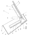
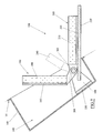
Figures 5 ,6 and7 schematically show the seat for the passenger offigure 2 sectioned according to plane V-V indicated infigure 4 , and in three different positions. -
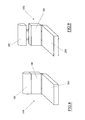
Figures 8 and 9 very schematically show a seat according to a variant of the present invention in two different configurations. - The agricultural tractor (not visible in its entirety in the accompanying figures) is an agricultural work vehicle that generally comprises two pairs of wheels arranged respectively on a front axle and a rear axle, an internal combustion engine positioned inside an engine compartment placed at the front of the tractor, substantially between the wheels of the front axle, and a transmission system able to transfer the mechanical power generated by the engine to the wheels.
- The agricultural tractor further comprises a passenger cabin for the driver and for an eventual passenger, which is generally located behind the engine compartment, positioned substantially between the wheels of the rear axle. As illustrated in
figure 1 , the interior of the agricultural tractor can be realized in the form of a true and proper cabin, which comprises a cover (not visible) and a series oftransparent side panels 100 which allow the driver a complete view of the surrounding environment. These transparent side panels generally include a front windshield, a rear window and two flanks, at least one of which is openable to enable ascent and descent of the driver and an eventual passenger. In other, more economic, embodiments, the cabin of the agricultural tractor could, however, be partially or fully open, i.e. without thepanels 100 and possibly also without covers. - The internal space of the cabin is also delimited by a series of cladding elements borrowed from the automobile sector, adapted to cover the visible parts of the body or other mechanical structures of the agricultural tractor, in order to improve the aesthetic appeal of the cabin and the driver's comfort. These cladding elements are generally suitably-shaped casings that can be made of a plastic material, for example via a hot-forming process, and then advantageously fixed to the inside of the cabin so as to cover the various parts to be clad.
- The cladding elements can include a front dashboard (not visible) able to cover the part of the body that separates the passenger compartment from the engine compartment, and two
lateral panels lateral panel 105 is separate and distanced from the front dashboard, in such a way as to create anarrow access corridor 112 enabling the driver to access and exit the cabin. - Various command organs of the agricultural tractor can be installed on the front dashboard and the
lateral panels - A
driver seat 115 is located internally of the cabin, which seat is positioned between the twolateral panels driver seat 115 is conformed as a chair provided with abackrest 120 and two lateral arms, of which aleft arm 125, made simply for resting an arm, and aright arm 130 for control of the vehicle, which has larger dimensions and in which various controls of the agricultural tractor can be integrated. - As illustrated in
figure 2 , the front wall of thelateral panel 105 facing theaccess corridor 112 affords afront opening 135, which places the interior space of the passenger in communication with ahidden compartment 140, a volume of which is contained within the volume of thelateral panel 105. - In particular, this
compartment 140 is posteriorly and laterally delimited by abin 145, which branches from an edge of thefront opening 135 of thelateral panel 105, in such a way that the concavity thereof is turned towards an inside of the cabin. In the illustrated example, thebin 145 is realized as a separate body with respect to thelateral panel 105, for example is made of a plastic material by means of a further hot-forming process, which separate body is inserted into thefront opening 135 and is fixed along the edge of the front opening using a heat-welding process, gluing or any other known system. In other embodiments, thebin 145 could however be formed in a single body with thelateral panel 105, for example using the same plastic material and by means of a single hot-forming process. In this case, the edge of thebin 145 would in fact also define thefront opening 135 of thelateral panel 105. - A small auxiliary seat is housed in the
compartment 140, which auxiliary seat is denoted in its entirety byreference number 150 infigure 2 ; theauxiliary chair 150 is intended for use by a passenger needing to be transported on-board the cabin of the agricultural tractor. - As illustrated in
figures 3 and 4 , thechair 150 primarily comprises a first connectingplate 155 intended to be fixed on the rear wall or bottom of thebin 145, for example by means of a series of bolts that can possibly also fasten on a rear wheel-well (seefigures 5-8 ). Two profiledplates 160 branch from the connectingplate 155, whichplates 160 are vertically-orientated, mutually facing, and separated by a certain distance. The connectingplate 155 and the profiledplates 160 are preferably made of a metal material and are solidly constrained to one another, for example by welding, so as to form an overall single rigid element. - The end portion of each profiled
plate 160 exhibits a through-hole (not visible), which is aligned with the through-hole afforded in the end portion of the other profiledplate 160. These two mutually aligned through-holes are able to receive ahinge pin 165, which is distanced from the connectingplate 155 and is perpendicular to the profiledplates 160, so as to be horizontally orientated. Thechair 150 further comprises a backrest, denoted in its entirety by 180. As illustrated for example infigures 3 and 4 , thebackrest 180 comprises asupport plate 185, which is orientated parallel to thehinge pin 165 and is covered with a layer ofsoft material 190. Two profiledplates 200 are fixed to a lower edge of thesupport plate 185, which profiledplates 200 are orientated perpendicular to thehinge pin 165, face each other and are separated by a distance of less than a distance separating the profiledplates 160 of the connectingplate 155. Thesupport plate 185 and the profiledplates 200 are preferably made of a metal material and are solidly constrained to one another, for example by welding, so as to form a single rigid element. - The profiled
plates 200 of thebackrest 180 are accommodated between the profiledplates 160 of the connectingplate 155 and exhibit through-holes (not visible), by means of which they are rotatably coupled to thehinge pin 165, so as to define a pair of hinges that enable thebackrest 180 to rotate with respect to the connectingplate 155, between the rest position shown infigure 5 and the use position shown infigures 7 and2 . - In the rest position, the
backrest 180 is completely contained internally of thecompartment 140, with thesupport plate 185 orientated substantially parallel to the connectingplate 155. In the use position, thebackrest 180 partially projects inside the vehicle through thefront opening 135 of thelateral panel 105, and is orientated substantially vertically or possibly slightly inclined. The rotation of thebackrest 180 can be limited between the rest and use positions of by means of suitable limit switches. - The
chair 150 also includes a seat, denoted in its entirety by 205. As illustrated infigures 3 and 4 , theseat 205 also comprises asupport plate 210, which is orientated parallel to thehinge pin 165 and is covered with a pad ofsoft material 215. Twobushings 217 are fixed to a rear edge of thesupport plate 210, which twobushings 217 are mutually coaxially arranged and are separated by a distance greater than a distance separating the profiledplates 160 of the connectingplate 155. Thesupport plate 210 andbushings 217 are preferably made of a metal material and are solidly constrained to one another, for example by welding, so as to form a single rigid element. - The
bushings 217 are positioned in such a way as to embrace the profiledplates 160 of the connectingplate 155 and are rotatably threaded on thehinge pin 165, so as to define a pair of hinges enabling theseat 205 to rotate with respect both to the connectingplate 155 and to thebackrest 180. - In particular, the
seat 205 can rotate with respect to theconnection plate 155 between the rest position shown infigure 5 and the use position shown infigure 7 . - In the rest position, the
seat 205 is completely contained internally of thecompartment 140, with the supportingplate 210 orientated substantially parallel to the connectingplate 155. In the use position, theseat 205 projects almost completely internally of the vehicle through thefront opening 135 of thelateral panel 105, and is orientated substantially horizontally. The rotation of theseat 205 can be limited between the rest and use positions by means of suitable end run devices. - As mentioned herein above, the
seat 205 can also rotate relative to thebackrest 180 between the closed configuration shown infigure 5 and the open configuration shown infigures 6 and7 . - In the closed configuration, the
seat 205 is substantially parallel and superimposed on thebackrest 180, with the respective paddings ofsoft material chair 150. In the open configuration, theseat 205 is instead orientated substantially at right angles relative to thebackrest 180, so as to enable use of thechair 150. The rotation of theseat 205 relative to thebackrest 180 between the rest and use positions can be limited by means of suitable endrun devices. - With the above-described specifications, when the
backrest 180 and theseat 205 are both in the rest position, thechair 150 is in the closed configuration and is completely contained within thecompartment 140, as illustrated infigure 5 . Starting from the initial configuration, theseat 205 can be manually rotated towards the use position thereof. During the rotation, thebackrest 180 remains stationary until theseat 205 is perpendicular thereto as shown infigure 6 . From this intermediate configuration, by continuing to rotate theseat 205 towards the use position, a simultaneous forward rotation of thebackrest 180 also takes place. This movement stops when theseat 205 and thebackrest 180 simultaneously reach the respective use positions, in which thechair 150 is in the open configuration and projects internally of the vehicle so that it can be used, as shown infigures 7 and2 . Thechair 150 can then, obviously, be returned from this configuration into the initial configuration by simply being rotated in the opposite direction, up until theseat 205 and thebackrest 180 have both returned into the relative rest positions, in which they are completely contained inside thelateral panel 105. - With this solution, when the
chair 150 is housed in thecompartment 140 the available space in the passenger compartment is advantageously increased, as is also the safety aspect, since the seat does not clutter theaccess corridor 112 in an emergency. - As illustrated in all the figures, a
lid 225 is also associated to thechair 150, whichlid 225 is fixed to the lower face of thesupport plate 210 of theseat 205, opposite the pad ofsoft material 215, and is shaped so as to completely or almost completely close thefront opening 135 of theside panel 105, when both theseat 205 and thebackrest 180 are in the rest position, so as to hide theseat 205 andbackrest 180 inside the compartment 140 (seefigures 1 and5 ). Thelid 225 can be profiled so as to provide a handle 230 (only visible infigures 1 and2 ) that can be grasped by a user to bring theseat 205 and the backrest into the use position when required. Thelid 225 can be made of a plastic material, for example by means of a hot-forming process, and then be fixed to thesupport plate 210 of theseat 205 by means of any system of known type. - As illustrated in
figure 3 , thechair 150 also includes an elastically-acting element, in the present case agas spring 235, ends of which are hinged respectively to the connectingplate 155 and thesupport plate 210 of theseat 205, so as to be also completely contained internally of thecompartment 140 of thelateral panel 105 when theseat 205 is in the non-use position. In particular, the hinge points of thegas spring 235 are chosen so that thespring 235 will push the seat 205 (and thus indirectly also the backrest 180) tendentially into the rest position thereof. In this way, in the rest position theseat 205 will be prevented from vibrating, as thelid 225 will strike against thelateral panel 105 following jolts to which the agricultural tractor will be subjected, for example during normal use thereof in fields. - Lastly, the
chair 150 is equipped with a conventional safety belt for the passenger sitting on theseat 205. The safety belt (of which only theengagement socket 240 is visible in the figures) is generally fixed to the connectingplate 155 so as also to remain enclosed within thecompartment 140 of thelateral panel 105 when theseat 205 is in the rest position. - In conclusion, it is specified that in a further embodiment, the
chair 150 can also comprise means for regulating the height of thebackrest 180 relative to theseat 205 when both are in the use position, so that the chair is made more comfortable and ergonomic. For example, the pad ofsoft material 215 could be fixed to an auxiliary plate, which might in turn be fixed on thesupport plate 210 so as to be able to slide on it upwards and downwards when thebackrest 180 is in the use position. Alternatively, as illustrated infigures 8 and 9 , thebackrest 180 might include anupper portion 182, able to slide vertically relative to a lower portion of thebackrest 180, when thebackrest 180 is in the use position. - Obviously a technical expert of the sector might make numerous modifications of a technical-applicational nature to the invention as described in the foregoing, if not thereby forsaking the scope of the invention as claimed in the following.
Claims (7)
- An agricultural work vehicle comprising a cabin and at least a cladding element (105) for delimiting an internal space of the cabin, the cladding element (105) comprising an opening (135) able to place the internal space of the cabin in communication with a compartment (140) in which at least a seat (205) is housed, the seat (205) being mobile with respect to the cladding element (105) by means of hinge means (165, 217) which enable the seating (205) to rotate about a substantially horizontal axis between a rest position in which it is completely contained in the compartment (140), and a use position, in which it is orientated horizontally and at least partly projects into an internal space of the cabin, a backrest (180) for the seat (205) being also housed in the compartment (140), characterised the backrest (180) being mobile with respect to the cladding element (105) by means of second hinge means (165, 200) which enable the backrest to rotate about an axis that is parallel to the rotation axis of the seat (205) between a rest position, in which it is completely contained in the compartment (140), and a use position, in which it is vertically orientated and at least partially projects into the internal space of the cabin.
- The vehicle of claim 1, characterised in that a lid (225) is fixed to the seat (205), which lid (225) is able to close the opening (135) of the cladding element (105) when the seat (205) is in the rest position.
- The vehicle of any one of the preceding claims, characterised in that the compartment (140) is delimited by a bin (145) which branches from the opening (135) of the cladding element (105).
- The vehicle of any one of the preceding claims, characterised in that it comprises at least an elastically yielding element (235) able to push the seat (205) towards the rest position.
- The vehicle of claim 1, characterized in that the seat (205) and the backrest (180) are reciprocally mobile between a closed configuration, in which they are substantially parallel and superposed, and an open configuration, in which they are arranged substantially at a right angle.
- The vehicle of claim 1, characterised in that it comprises means for regulating a distance of the backrest (180) from the seat (205) when both are in use position.
- The vehicle of claim 1, characterised in that the first and the second hinge means are configured such that the rotation axis of the backrest (180) coincides with the rotation axis of the seat (205).
Applications Claiming Priority (1)
| Application Number | Priority Date | Filing Date | Title |
|---|---|---|---|
| IT000010A ITRE20130010A1 (en) | 2013-02-21 | 2013-02-21 | WORKING AGRICULTURAL VEHICLE |
Publications (2)
| Publication Number | Publication Date |
|---|---|
| EP2769877A1 EP2769877A1 (en) | 2014-08-27 |
| EP2769877B1 true EP2769877B1 (en) | 2015-11-04 |
Family
ID=48096069
Family Applications (1)
| Application Number | Title | Priority Date | Filing Date |
|---|---|---|---|
| EP14155512.8A Active EP2769877B1 (en) | 2013-02-21 | 2014-02-18 | An agricultural work vehicle |
Country Status (3)
| Country | Link |
|---|---|
| US (1) | US9016754B2 (en) |
| EP (1) | EP2769877B1 (en) |
| IT (1) | ITRE20130010A1 (en) |
Families Citing this family (2)
| Publication number | Priority date | Publication date | Assignee | Title |
|---|---|---|---|---|
| KR102638796B1 (en) * | 2016-11-24 | 2024-02-20 | 주식회사 대동 | Folding instructional seat for an agricultural work vehicle |
| CN110433407B (en) * | 2019-07-22 | 2020-12-15 | 江西云帆环保建材有限公司 | High-altitude buffering escape and pressurization spraying device for building |
Citations (4)
| Publication number | Priority date | Publication date | Assignee | Title |
|---|---|---|---|---|
| US1412367A (en) * | 1920-11-04 | 1922-04-11 | Murphy Door Bed Company | Disappearing structure |
| US4527828A (en) | 1983-08-08 | 1985-07-09 | General Motors Corporation | Side mounted jump seat for an automotive vehicle |
| FR2724608A1 (en) | 1994-09-21 | 1996-03-22 | Peugeot | Child seat integrated into dashboard of vehicle |
| US5797649A (en) | 1996-12-02 | 1998-08-25 | Case Corporation | Folding auxiliary seat for a vehicle |
Family Cites Families (11)
| Publication number | Priority date | Publication date | Assignee | Title |
|---|---|---|---|---|
| US1323693A (en) * | 1919-12-02 | Folding seat for vehicles | ||
| US954222A (en) * | 1909-07-10 | 1910-04-05 | Melville R Bissell | Disappearing chair. |
| US1698036A (en) * | 1927-10-28 | 1929-01-08 | El Paso Sash & Door Company | Built-ing wall seat |
| JPS59216736A (en) * | 1983-05-23 | 1984-12-06 | Ikeda Bussan Co Ltd | Jump seat |
| IT219148Z2 (en) * | 1989-11-27 | 1992-12-11 | Same Spa | AUXILIARY SEAT FOR AGRICULTURAL TRACTORS |
| US5533774A (en) * | 1995-04-03 | 1996-07-09 | Cavanaugh; James C. | Vehicle exterior body panel seat |
| DE69731871T2 (en) * | 1996-11-12 | 2005-04-07 | Cnh Belgium N.V. | Double joint seat with sliding tray |
| JP4306735B2 (en) * | 2007-01-31 | 2009-08-05 | トヨタ自動車株式会社 | Vehicle seat |
| JP2009292405A (en) * | 2008-06-09 | 2009-12-17 | Toyota Boshoku Corp | Vehicular seat |
| DE102009034681A1 (en) * | 2009-07-24 | 2011-02-03 | Bombardier Transportation Gmbh | Rail vehicle with a folding seat device |
| US8708393B2 (en) * | 2012-06-25 | 2014-04-29 | Chrysler Group Llc | Stowable seating arrangement for a vehicle |
-
2013
- 2013-02-21 IT IT000010A patent/ITRE20130010A1/en unknown
-
2014
- 2014-02-18 EP EP14155512.8A patent/EP2769877B1/en active Active
- 2014-02-19 US US14/184,385 patent/US9016754B2/en not_active Expired - Fee Related
Patent Citations (4)
| Publication number | Priority date | Publication date | Assignee | Title |
|---|---|---|---|---|
| US1412367A (en) * | 1920-11-04 | 1922-04-11 | Murphy Door Bed Company | Disappearing structure |
| US4527828A (en) | 1983-08-08 | 1985-07-09 | General Motors Corporation | Side mounted jump seat for an automotive vehicle |
| FR2724608A1 (en) | 1994-09-21 | 1996-03-22 | Peugeot | Child seat integrated into dashboard of vehicle |
| US5797649A (en) | 1996-12-02 | 1998-08-25 | Case Corporation | Folding auxiliary seat for a vehicle |
Also Published As
| Publication number | Publication date |
|---|---|
| ITRE20130010A1 (en) | 2014-08-22 |
| US20140232139A1 (en) | 2014-08-21 |
| US9016754B2 (en) | 2015-04-28 |
| EP2769877A1 (en) | 2014-08-27 |
Similar Documents
| Publication | Publication Date | Title |
|---|---|---|
| EP1564058B1 (en) | Fuel tank disposition structure and vehicle provided therewith | |
| CN104395183B (en) | small vehicle | |
| EP2137024B1 (en) | Compact seating arrangement | |
| EP1520748B1 (en) | Vehicular seat structure | |
| JP2010502498A (en) | Vehicle seat | |
| US5538309A (en) | Vehicle body | |
| US20180186253A1 (en) | Vehicle with moveable interior door panel | |
| US6585073B2 (en) | Device for steering a motor vehicle | |
| EP0677002B1 (en) | Vehicle body | |
| US9016754B2 (en) | Agricultural work vehicle | |
| CA2847554C (en) | Cabin space structure for all terrain vehicle | |
| US7140656B2 (en) | Motor vehicle with partition | |
| CN110550109A (en) | light vehicle | |
| JP5808376B2 (en) | Storage structure for rough terrain vehicle | |
| JP7589651B2 (en) | Vehicle front structure | |
| CN216761417U (en) | Vehicle with front-back riding channel | |
| KR20090005151A (en) | Car cabin with adaptive opening | |
| KR101285703B1 (en) | Vehicles equipped space where you can relax | |
| JPH107018A (en) | Car body | |
| JP2010076674A (en) | Lower vehicle body structure for vehicle | |
| CN210337846U (en) | Driver surrounding assembly convenient for assembling taxi driver | |
| GB2282576A (en) | Vehicle seating arrangement | |
| JP2025155235A (en) | Multipurpose vehicle | |
| JP5286920B2 (en) | Vehicle seat device | |
| JP2025155236A (en) | Multipurpose vehicle |
Legal Events
| Date | Code | Title | Description |
|---|---|---|---|
| PUAI | Public reference made under article 153(3) epc to a published international application that has entered the european phase |
Free format text: ORIGINAL CODE: 0009012 |
|
| 17P | Request for examination filed |
Effective date: 20140218 |
|
| AK | Designated contracting states |
Kind code of ref document: A1 Designated state(s): AL AT BE BG CH CY CZ DE DK EE ES FI FR GB GR HR HU IE IS IT LI LT LU LV MC MK MT NL NO PL PT RO RS SE SI SK SM TR |
|
| AX | Request for extension of the european patent |
Extension state: BA ME |
|
| R17P | Request for examination filed (corrected) |
Effective date: 20150224 |
|
| RBV | Designated contracting states (corrected) |
Designated state(s): AL AT BE BG CH CY CZ DE DK EE ES FI FR GB GR HR HU IE IS IT LI LT LU LV MC MK MT NL NO PL PT RO RS SE SI SK SM TR |
|
| REG | Reference to a national code |
Ref country code: DE Ref legal event code: R079 Ref document number: 602014000402 Country of ref document: DE Free format text: PREVIOUS MAIN CLASS: B60N0002300000 Ipc: B60N0002480000 |
|
| GRAP | Despatch of communication of intention to grant a patent |
Free format text: ORIGINAL CODE: EPIDOSNIGR1 |
|
| RIC1 | Information provided on ipc code assigned before grant |
Ipc: B62D 33/06 20060101ALI20150417BHEP Ipc: B60N 2/48 20060101AFI20150417BHEP Ipc: B60N 2/38 20060101ALI20150417BHEP |
|
| INTG | Intention to grant announced |
Effective date: 20150528 |
|
| GRAS | Grant fee paid |
Free format text: ORIGINAL CODE: EPIDOSNIGR3 |
|
| GRAA | (expected) grant |
Free format text: ORIGINAL CODE: 0009210 |
|
| AK | Designated contracting states |
Kind code of ref document: B1 Designated state(s): AL AT BE BG CH CY CZ DE DK EE ES FI FR GB GR HR HU IE IS IT LI LT LU LV MC MK MT NL NO PL PT RO RS SE SI SK SM TR |
|
| REG | Reference to a national code |
Ref country code: GB Ref legal event code: FG4D |
|
| REG | Reference to a national code |
Ref country code: CH Ref legal event code: EP |
|
| REG | Reference to a national code |
Ref country code: AT Ref legal event code: REF Ref document number: 758941 Country of ref document: AT Kind code of ref document: T Effective date: 20151115 |
|
| REG | Reference to a national code |
Ref country code: IE Ref legal event code: FG4D |
|
| REG | Reference to a national code |
Ref country code: DE Ref legal event code: R096 Ref document number: 602014000402 Country of ref document: DE |
|
| REG | Reference to a national code |
Ref country code: FR Ref legal event code: PLFP Year of fee payment: 3 |
|
| REG | Reference to a national code |
Ref country code: NL Ref legal event code: MP Effective date: 20151104 |
|
| REG | Reference to a national code |
Ref country code: LT Ref legal event code: MG4D |
|
| REG | Reference to a national code |
Ref country code: AT Ref legal event code: MK05 Ref document number: 758941 Country of ref document: AT Kind code of ref document: T Effective date: 20151104 |
|
| PG25 | Lapsed in a contracting state [announced via postgrant information from national office to epo] |
Ref country code: IS Free format text: LAPSE BECAUSE OF FAILURE TO SUBMIT A TRANSLATION OF THE DESCRIPTION OR TO PAY THE FEE WITHIN THE PRESCRIBED TIME-LIMIT Effective date: 20160304 Ref country code: IT Free format text: LAPSE BECAUSE OF FAILURE TO SUBMIT A TRANSLATION OF THE DESCRIPTION OR TO PAY THE FEE WITHIN THE PRESCRIBED TIME-LIMIT Effective date: 20151104 Ref country code: NO Free format text: LAPSE BECAUSE OF FAILURE TO SUBMIT A TRANSLATION OF THE DESCRIPTION OR TO PAY THE FEE WITHIN THE PRESCRIBED TIME-LIMIT Effective date: 20160204 Ref country code: LT Free format text: LAPSE BECAUSE OF FAILURE TO SUBMIT A TRANSLATION OF THE DESCRIPTION OR TO PAY THE FEE WITHIN THE PRESCRIBED TIME-LIMIT Effective date: 20151104 Ref country code: NL Free format text: LAPSE BECAUSE OF FAILURE TO SUBMIT A TRANSLATION OF THE DESCRIPTION OR TO PAY THE FEE WITHIN THE PRESCRIBED TIME-LIMIT Effective date: 20151104 Ref country code: HR Free format text: LAPSE BECAUSE OF FAILURE TO SUBMIT A TRANSLATION OF THE DESCRIPTION OR TO PAY THE FEE WITHIN THE PRESCRIBED TIME-LIMIT Effective date: 20151104 Ref country code: ES Free format text: LAPSE BECAUSE OF FAILURE TO SUBMIT A TRANSLATION OF THE DESCRIPTION OR TO PAY THE FEE WITHIN THE PRESCRIBED TIME-LIMIT Effective date: 20151104 |
|
| PG25 | Lapsed in a contracting state [announced via postgrant information from national office to epo] |
Ref country code: GR Free format text: LAPSE BECAUSE OF FAILURE TO SUBMIT A TRANSLATION OF THE DESCRIPTION OR TO PAY THE FEE WITHIN THE PRESCRIBED TIME-LIMIT Effective date: 20160205 Ref country code: BE Free format text: LAPSE BECAUSE OF NON-PAYMENT OF DUE FEES Effective date: 20160229 Ref country code: PL Free format text: LAPSE BECAUSE OF FAILURE TO SUBMIT A TRANSLATION OF THE DESCRIPTION OR TO PAY THE FEE WITHIN THE PRESCRIBED TIME-LIMIT Effective date: 20151104 Ref country code: AT Free format text: LAPSE BECAUSE OF FAILURE TO SUBMIT A TRANSLATION OF THE DESCRIPTION OR TO PAY THE FEE WITHIN THE PRESCRIBED TIME-LIMIT Effective date: 20151104 Ref country code: RS Free format text: LAPSE BECAUSE OF FAILURE TO SUBMIT A TRANSLATION OF THE DESCRIPTION OR TO PAY THE FEE WITHIN THE PRESCRIBED TIME-LIMIT Effective date: 20151104 Ref country code: PT Free format text: LAPSE BECAUSE OF FAILURE TO SUBMIT A TRANSLATION OF THE DESCRIPTION OR TO PAY THE FEE WITHIN THE PRESCRIBED TIME-LIMIT Effective date: 20160304 Ref country code: FI Free format text: LAPSE BECAUSE OF FAILURE TO SUBMIT A TRANSLATION OF THE DESCRIPTION OR TO PAY THE FEE WITHIN THE PRESCRIBED TIME-LIMIT Effective date: 20151104 Ref country code: LV Free format text: LAPSE BECAUSE OF FAILURE TO SUBMIT A TRANSLATION OF THE DESCRIPTION OR TO PAY THE FEE WITHIN THE PRESCRIBED TIME-LIMIT Effective date: 20151104 Ref country code: SE Free format text: LAPSE BECAUSE OF FAILURE TO SUBMIT A TRANSLATION OF THE DESCRIPTION OR TO PAY THE FEE WITHIN THE PRESCRIBED TIME-LIMIT Effective date: 20151104 |
|
| REG | Reference to a national code |
Ref country code: DE Ref legal event code: R026 Ref document number: 602014000402 Country of ref document: DE |
|
| PG25 | Lapsed in a contracting state [announced via postgrant information from national office to epo] |
Ref country code: CZ Free format text: LAPSE BECAUSE OF FAILURE TO SUBMIT A TRANSLATION OF THE DESCRIPTION OR TO PAY THE FEE WITHIN THE PRESCRIBED TIME-LIMIT Effective date: 20151104 |
|
| PLBI | Opposition filed |
Free format text: ORIGINAL CODE: 0009260 |
|
| 26 | Opposition filed |
Opponent name: CNH INDUSTRIAL BELGIUM NV Effective date: 20160720 |
|
| PG25 | Lapsed in a contracting state [announced via postgrant information from national office to epo] |
Ref country code: SK Free format text: LAPSE BECAUSE OF FAILURE TO SUBMIT A TRANSLATION OF THE DESCRIPTION OR TO PAY THE FEE WITHIN THE PRESCRIBED TIME-LIMIT Effective date: 20151104 Ref country code: SM Free format text: LAPSE BECAUSE OF FAILURE TO SUBMIT A TRANSLATION OF THE DESCRIPTION OR TO PAY THE FEE WITHIN THE PRESCRIBED TIME-LIMIT Effective date: 20151104 Ref country code: EE Free format text: LAPSE BECAUSE OF FAILURE TO SUBMIT A TRANSLATION OF THE DESCRIPTION OR TO PAY THE FEE WITHIN THE PRESCRIBED TIME-LIMIT Effective date: 20151104 Ref country code: DK Free format text: LAPSE BECAUSE OF FAILURE TO SUBMIT A TRANSLATION OF THE DESCRIPTION OR TO PAY THE FEE WITHIN THE PRESCRIBED TIME-LIMIT Effective date: 20151104 Ref country code: RO Free format text: LAPSE BECAUSE OF FAILURE TO SUBMIT A TRANSLATION OF THE DESCRIPTION OR TO PAY THE FEE WITHIN THE PRESCRIBED TIME-LIMIT Effective date: 20151104 |
|
| PLAX | Notice of opposition and request to file observation + time limit sent |
Free format text: ORIGINAL CODE: EPIDOSNOBS2 |
|
| PG25 | Lapsed in a contracting state [announced via postgrant information from national office to epo] |
Ref country code: MC Free format text: LAPSE BECAUSE OF FAILURE TO SUBMIT A TRANSLATION OF THE DESCRIPTION OR TO PAY THE FEE WITHIN THE PRESCRIBED TIME-LIMIT Effective date: 20151104 Ref country code: LU Free format text: LAPSE BECAUSE OF FAILURE TO SUBMIT A TRANSLATION OF THE DESCRIPTION OR TO PAY THE FEE WITHIN THE PRESCRIBED TIME-LIMIT Effective date: 20160218 |
|
| PG25 | Lapsed in a contracting state [announced via postgrant information from national office to epo] |
Ref country code: SI Free format text: LAPSE BECAUSE OF FAILURE TO SUBMIT A TRANSLATION OF THE DESCRIPTION OR TO PAY THE FEE WITHIN THE PRESCRIBED TIME-LIMIT Effective date: 20151104 |
|
| REG | Reference to a national code |
Ref country code: IE Ref legal event code: MM4A |
|
| PG25 | Lapsed in a contracting state [announced via postgrant information from national office to epo] |
Ref country code: BE Free format text: LAPSE BECAUSE OF FAILURE TO SUBMIT A TRANSLATION OF THE DESCRIPTION OR TO PAY THE FEE WITHIN THE PRESCRIBED TIME-LIMIT Effective date: 20151104 |
|
| PLBB | Reply of patent proprietor to notice(s) of opposition received |
Free format text: ORIGINAL CODE: EPIDOSNOBS3 |
|
| PG25 | Lapsed in a contracting state [announced via postgrant information from national office to epo] |
Ref country code: IE Free format text: LAPSE BECAUSE OF NON-PAYMENT OF DUE FEES Effective date: 20160218 |
|
| REG | Reference to a national code |
Ref country code: FR Ref legal event code: PLFP Year of fee payment: 4 |
|
| PG25 | Lapsed in a contracting state [announced via postgrant information from national office to epo] |
Ref country code: MT Free format text: LAPSE BECAUSE OF FAILURE TO SUBMIT A TRANSLATION OF THE DESCRIPTION OR TO PAY THE FEE WITHIN THE PRESCRIBED TIME-LIMIT Effective date: 20151104 |
|
| REG | Reference to a national code |
Ref country code: CH Ref legal event code: PL |
|
| PG25 | Lapsed in a contracting state [announced via postgrant information from national office to epo] |
Ref country code: CH Free format text: LAPSE BECAUSE OF NON-PAYMENT OF DUE FEES Effective date: 20170228 Ref country code: LI Free format text: LAPSE BECAUSE OF NON-PAYMENT OF DUE FEES Effective date: 20170228 |
|
| REG | Reference to a national code |
Ref country code: DE Ref legal event code: R079 Ref document number: 602014000402 Country of ref document: DE Free format text: PREVIOUS MAIN CLASS: B60N0002480000 Ipc: B60N0002800000 |
|
| REG | Reference to a national code |
Ref country code: DE Ref legal event code: R100 Ref document number: 602014000402 Country of ref document: DE |
|
| REG | Reference to a national code |
Ref country code: FR Ref legal event code: PLFP Year of fee payment: 5 |
|
| PLCK | Communication despatched that opposition was rejected |
Free format text: ORIGINAL CODE: EPIDOSNREJ1 |
|
| PG25 | Lapsed in a contracting state [announced via postgrant information from national office to epo] |
Ref country code: HU Free format text: LAPSE BECAUSE OF FAILURE TO SUBMIT A TRANSLATION OF THE DESCRIPTION OR TO PAY THE FEE WITHIN THE PRESCRIBED TIME-LIMIT; INVALID AB INITIO Effective date: 20140218 Ref country code: CY Free format text: LAPSE BECAUSE OF FAILURE TO SUBMIT A TRANSLATION OF THE DESCRIPTION OR TO PAY THE FEE WITHIN THE PRESCRIBED TIME-LIMIT Effective date: 20151104 |
|
| PG25 | Lapsed in a contracting state [announced via postgrant information from national office to epo] |
Ref country code: TR Free format text: LAPSE BECAUSE OF FAILURE TO SUBMIT A TRANSLATION OF THE DESCRIPTION OR TO PAY THE FEE WITHIN THE PRESCRIBED TIME-LIMIT Effective date: 20151104 Ref country code: MT Free format text: LAPSE BECAUSE OF FAILURE TO SUBMIT A TRANSLATION OF THE DESCRIPTION OR TO PAY THE FEE WITHIN THE PRESCRIBED TIME-LIMIT Effective date: 20160229 Ref country code: MK Free format text: LAPSE BECAUSE OF FAILURE TO SUBMIT A TRANSLATION OF THE DESCRIPTION OR TO PAY THE FEE WITHIN THE PRESCRIBED TIME-LIMIT Effective date: 20151104 |
|
| PLBN | Opposition rejected |
Free format text: ORIGINAL CODE: 0009273 |
|
| STAA | Information on the status of an ep patent application or granted ep patent |
Free format text: STATUS: OPPOSITION REJECTED |
|
| PG25 | Lapsed in a contracting state [announced via postgrant information from national office to epo] |
Ref country code: BG Free format text: LAPSE BECAUSE OF FAILURE TO SUBMIT A TRANSLATION OF THE DESCRIPTION OR TO PAY THE FEE WITHIN THE PRESCRIBED TIME-LIMIT Effective date: 20151104 |
|
| 27O | Opposition rejected |
Effective date: 20180125 |
|
| PG25 | Lapsed in a contracting state [announced via postgrant information from national office to epo] |
Ref country code: AL Free format text: LAPSE BECAUSE OF FAILURE TO SUBMIT A TRANSLATION OF THE DESCRIPTION OR TO PAY THE FEE WITHIN THE PRESCRIBED TIME-LIMIT Effective date: 20151104 |
|
| PGFP | Annual fee paid to national office [announced via postgrant information from national office to epo] |
Ref country code: GB Payment date: 20260227 Year of fee payment: 13 |
|
| PGFP | Annual fee paid to national office [announced via postgrant information from national office to epo] |
Ref country code: DE Payment date: 20260227 Year of fee payment: 13 |
|
| PGFP | Annual fee paid to national office [announced via postgrant information from national office to epo] |
Ref country code: FR Payment date: 20260225 Year of fee payment: 13 |