EP2769874A2 - Vehicle and vehicle driving device - Google Patents
Vehicle and vehicle driving device Download PDFInfo
- Publication number
- EP2769874A2 EP2769874A2 EP14156584.6A EP14156584A EP2769874A2 EP 2769874 A2 EP2769874 A2 EP 2769874A2 EP 14156584 A EP14156584 A EP 14156584A EP 2769874 A2 EP2769874 A2 EP 2769874A2
- Authority
- EP
- European Patent Office
- Prior art keywords
- torque
- wheel
- motor
- wheel motor
- wheels
- Prior art date
- Legal status (The legal status is an assumption and is not a legal conclusion. Google has not performed a legal analysis and makes no representation as to the accuracy of the status listed.)
- Withdrawn
Links
Images


Classifications
-
- B—PERFORMING OPERATIONS; TRANSPORTING
- B60—VEHICLES IN GENERAL
- B60L—PROPULSION OF ELECTRICALLY-PROPELLED VEHICLES; SUPPLYING ELECTRIC POWER FOR AUXILIARY EQUIPMENT OF ELECTRICALLY-PROPELLED VEHICLES; ELECTRODYNAMIC BRAKE SYSTEMS FOR VEHICLES IN GENERAL; MAGNETIC SUSPENSION OR LEVITATION FOR VEHICLES; MONITORING OPERATING VARIABLES OF ELECTRICALLY-PROPELLED VEHICLES; ELECTRIC SAFETY DEVICES FOR ELECTRICALLY-PROPELLED VEHICLES
- B60L15/00—Methods, circuits, or devices for controlling the traction-motor speed of electrically-propelled vehicles
- B60L15/20—Methods, circuits, or devices for controlling the traction-motor speed of electrically-propelled vehicles for control of the vehicle or its driving motor to achieve a desired performance, e.g. speed, torque, programmed variation of speed
-
- B—PERFORMING OPERATIONS; TRANSPORTING
- B60—VEHICLES IN GENERAL
- B60K—ARRANGEMENT OR MOUNTING OF PROPULSION UNITS OR OF TRANSMISSIONS IN VEHICLES; ARRANGEMENT OR MOUNTING OF PLURAL DIVERSE PRIME-MOVERS IN VEHICLES; AUXILIARY DRIVES FOR VEHICLES; INSTRUMENTATION OR DASHBOARDS FOR VEHICLES; ARRANGEMENTS IN CONNECTION WITH COOLING, AIR INTAKE, GAS EXHAUST OR FUEL SUPPLY OF PROPULSION UNITS IN VEHICLES
- B60K1/00—Arrangement or mounting of electrical propulsion units
- B60K1/02—Arrangement or mounting of electrical propulsion units comprising more than one electric motor
-
- B—PERFORMING OPERATIONS; TRANSPORTING
- B60—VEHICLES IN GENERAL
- B60K—ARRANGEMENT OR MOUNTING OF PROPULSION UNITS OR OF TRANSMISSIONS IN VEHICLES; ARRANGEMENT OR MOUNTING OF PLURAL DIVERSE PRIME-MOVERS IN VEHICLES; AUXILIARY DRIVES FOR VEHICLES; INSTRUMENTATION OR DASHBOARDS FOR VEHICLES; ARRANGEMENTS IN CONNECTION WITH COOLING, AIR INTAKE, GAS EXHAUST OR FUEL SUPPLY OF PROPULSION UNITS IN VEHICLES
- B60K23/00—Arrangement or mounting of control devices for vehicle transmissions, or parts thereof, not otherwise provided for
- B60K23/08—Arrangement or mounting of control devices for vehicle transmissions, or parts thereof, not otherwise provided for for changing number of driven wheels, for switching from driving one axle to driving two or more axles
- B60K23/0808—Arrangement or mounting of control devices for vehicle transmissions, or parts thereof, not otherwise provided for for changing number of driven wheels, for switching from driving one axle to driving two or more axles for varying torque distribution between driven axles, e.g. by transfer clutch
-
- B—PERFORMING OPERATIONS; TRANSPORTING
- B60—VEHICLES IN GENERAL
- B60L—PROPULSION OF ELECTRICALLY-PROPELLED VEHICLES; SUPPLYING ELECTRIC POWER FOR AUXILIARY EQUIPMENT OF ELECTRICALLY-PROPELLED VEHICLES; ELECTRODYNAMIC BRAKE SYSTEMS FOR VEHICLES IN GENERAL; MAGNETIC SUSPENSION OR LEVITATION FOR VEHICLES; MONITORING OPERATING VARIABLES OF ELECTRICALLY-PROPELLED VEHICLES; ELECTRIC SAFETY DEVICES FOR ELECTRICALLY-PROPELLED VEHICLES
- B60L15/00—Methods, circuits, or devices for controlling the traction-motor speed of electrically-propelled vehicles
- B60L15/20—Methods, circuits, or devices for controlling the traction-motor speed of electrically-propelled vehicles for control of the vehicle or its driving motor to achieve a desired performance, e.g. speed, torque, programmed variation of speed
- B60L15/2036—Electric differentials, e.g. for supporting steering vehicles
-
- B—PERFORMING OPERATIONS; TRANSPORTING
- B60—VEHICLES IN GENERAL
- B60L—PROPULSION OF ELECTRICALLY-PROPELLED VEHICLES; SUPPLYING ELECTRIC POWER FOR AUXILIARY EQUIPMENT OF ELECTRICALLY-PROPELLED VEHICLES; ELECTRODYNAMIC BRAKE SYSTEMS FOR VEHICLES IN GENERAL; MAGNETIC SUSPENSION OR LEVITATION FOR VEHICLES; MONITORING OPERATING VARIABLES OF ELECTRICALLY-PROPELLED VEHICLES; ELECTRIC SAFETY DEVICES FOR ELECTRICALLY-PROPELLED VEHICLES
- B60L15/00—Methods, circuits, or devices for controlling the traction-motor speed of electrically-propelled vehicles
- B60L15/20—Methods, circuits, or devices for controlling the traction-motor speed of electrically-propelled vehicles for control of the vehicle or its driving motor to achieve a desired performance, e.g. speed, torque, programmed variation of speed
- B60L15/2045—Methods, circuits, or devices for controlling the traction-motor speed of electrically-propelled vehicles for control of the vehicle or its driving motor to achieve a desired performance, e.g. speed, torque, programmed variation of speed for optimising the use of energy
-
- B—PERFORMING OPERATIONS; TRANSPORTING
- B60—VEHICLES IN GENERAL
- B60L—PROPULSION OF ELECTRICALLY-PROPELLED VEHICLES; SUPPLYING ELECTRIC POWER FOR AUXILIARY EQUIPMENT OF ELECTRICALLY-PROPELLED VEHICLES; ELECTRODYNAMIC BRAKE SYSTEMS FOR VEHICLES IN GENERAL; MAGNETIC SUSPENSION OR LEVITATION FOR VEHICLES; MONITORING OPERATING VARIABLES OF ELECTRICALLY-PROPELLED VEHICLES; ELECTRIC SAFETY DEVICES FOR ELECTRICALLY-PROPELLED VEHICLES
- B60L15/00—Methods, circuits, or devices for controlling the traction-motor speed of electrically-propelled vehicles
- B60L15/20—Methods, circuits, or devices for controlling the traction-motor speed of electrically-propelled vehicles for control of the vehicle or its driving motor to achieve a desired performance, e.g. speed, torque, programmed variation of speed
- B60L15/2054—Methods, circuits, or devices for controlling the traction-motor speed of electrically-propelled vehicles for control of the vehicle or its driving motor to achieve a desired performance, e.g. speed, torque, programmed variation of speed by controlling transmissions or clutches
-
- B—PERFORMING OPERATIONS; TRANSPORTING
- B60—VEHICLES IN GENERAL
- B60W—CONJOINT CONTROL OF VEHICLE SUB-UNITS OF DIFFERENT TYPE OR DIFFERENT FUNCTION; CONTROL SYSTEMS SPECIALLY ADAPTED FOR HYBRID VEHICLES; ROAD VEHICLE DRIVE CONTROL SYSTEMS FOR PURPOSES NOT RELATED TO THE CONTROL OF A PARTICULAR SUB-UNIT
- B60W10/00—Conjoint control of vehicle sub-units of different type or different function
- B60W10/02—Conjoint control of vehicle sub-units of different type or different function including control of driveline clutches
-
- B—PERFORMING OPERATIONS; TRANSPORTING
- B60—VEHICLES IN GENERAL
- B60W—CONJOINT CONTROL OF VEHICLE SUB-UNITS OF DIFFERENT TYPE OR DIFFERENT FUNCTION; CONTROL SYSTEMS SPECIALLY ADAPTED FOR HYBRID VEHICLES; ROAD VEHICLE DRIVE CONTROL SYSTEMS FOR PURPOSES NOT RELATED TO THE CONTROL OF A PARTICULAR SUB-UNIT
- B60W10/00—Conjoint control of vehicle sub-units of different type or different function
- B60W10/04—Conjoint control of vehicle sub-units of different type or different function including control of propulsion units
- B60W10/08—Conjoint control of vehicle sub-units of different type or different function including control of propulsion units including control of electric propulsion units, e.g. motors or generators
-
- B—PERFORMING OPERATIONS; TRANSPORTING
- B60—VEHICLES IN GENERAL
- B60K—ARRANGEMENT OR MOUNTING OF PROPULSION UNITS OR OF TRANSMISSIONS IN VEHICLES; ARRANGEMENT OR MOUNTING OF PLURAL DIVERSE PRIME-MOVERS IN VEHICLES; AUXILIARY DRIVES FOR VEHICLES; INSTRUMENTATION OR DASHBOARDS FOR VEHICLES; ARRANGEMENTS IN CONNECTION WITH COOLING, AIR INTAKE, GAS EXHAUST OR FUEL SUPPLY OF PROPULSION UNITS IN VEHICLES
- B60K17/00—Arrangement or mounting of transmissions in vehicles
- B60K17/34—Arrangement or mounting of transmissions in vehicles for driving both front and rear wheels, e.g. four wheel drive vehicles
- B60K17/348—Arrangement or mounting of transmissions in vehicles for driving both front and rear wheels, e.g. four wheel drive vehicles having differential means for driving one set of wheels, e.g. the front, at one speed and the other set, e.g. the rear, at a different speed
- B60K17/35—Arrangement or mounting of transmissions in vehicles for driving both front and rear wheels, e.g. four wheel drive vehicles having differential means for driving one set of wheels, e.g. the front, at one speed and the other set, e.g. the rear, at a different speed including arrangements for suppressing or influencing the power transfer, e.g. viscous clutches
- B60K17/3505—Arrangement or mounting of transmissions in vehicles for driving both front and rear wheels, e.g. four wheel drive vehicles having differential means for driving one set of wheels, e.g. the front, at one speed and the other set, e.g. the rear, at a different speed including arrangements for suppressing or influencing the power transfer, e.g. viscous clutches with self-actuated means, e.g. by difference of speed
-
- B—PERFORMING OPERATIONS; TRANSPORTING
- B60—VEHICLES IN GENERAL
- B60K—ARRANGEMENT OR MOUNTING OF PROPULSION UNITS OR OF TRANSMISSIONS IN VEHICLES; ARRANGEMENT OR MOUNTING OF PLURAL DIVERSE PRIME-MOVERS IN VEHICLES; AUXILIARY DRIVES FOR VEHICLES; INSTRUMENTATION OR DASHBOARDS FOR VEHICLES; ARRANGEMENTS IN CONNECTION WITH COOLING, AIR INTAKE, GAS EXHAUST OR FUEL SUPPLY OF PROPULSION UNITS IN VEHICLES
- B60K17/00—Arrangement or mounting of transmissions in vehicles
- B60K17/34—Arrangement or mounting of transmissions in vehicles for driving both front and rear wheels, e.g. four wheel drive vehicles
- B60K17/356—Arrangement or mounting of transmissions in vehicles for driving both front and rear wheels, e.g. four wheel drive vehicles having fluid or electric motor, for driving one or more wheels
-
- B—PERFORMING OPERATIONS; TRANSPORTING
- B60—VEHICLES IN GENERAL
- B60L—PROPULSION OF ELECTRICALLY-PROPELLED VEHICLES; SUPPLYING ELECTRIC POWER FOR AUXILIARY EQUIPMENT OF ELECTRICALLY-PROPELLED VEHICLES; ELECTRODYNAMIC BRAKE SYSTEMS FOR VEHICLES IN GENERAL; MAGNETIC SUSPENSION OR LEVITATION FOR VEHICLES; MONITORING OPERATING VARIABLES OF ELECTRICALLY-PROPELLED VEHICLES; ELECTRIC SAFETY DEVICES FOR ELECTRICALLY-PROPELLED VEHICLES
- B60L2220/00—Electrical machine types; Structures or applications thereof
- B60L2220/40—Electrical machine applications
- B60L2220/44—Wheel Hub motors, i.e. integrated in the wheel hub
-
- B—PERFORMING OPERATIONS; TRANSPORTING
- B60—VEHICLES IN GENERAL
- B60L—PROPULSION OF ELECTRICALLY-PROPELLED VEHICLES; SUPPLYING ELECTRIC POWER FOR AUXILIARY EQUIPMENT OF ELECTRICALLY-PROPELLED VEHICLES; ELECTRODYNAMIC BRAKE SYSTEMS FOR VEHICLES IN GENERAL; MAGNETIC SUSPENSION OR LEVITATION FOR VEHICLES; MONITORING OPERATING VARIABLES OF ELECTRICALLY-PROPELLED VEHICLES; ELECTRIC SAFETY DEVICES FOR ELECTRICALLY-PROPELLED VEHICLES
- B60L2220/00—Electrical machine types; Structures or applications thereof
- B60L2220/40—Electrical machine applications
- B60L2220/46—Wheel motors, i.e. motor connected to only one wheel
-
- B—PERFORMING OPERATIONS; TRANSPORTING
- B60—VEHICLES IN GENERAL
- B60L—PROPULSION OF ELECTRICALLY-PROPELLED VEHICLES; SUPPLYING ELECTRIC POWER FOR AUXILIARY EQUIPMENT OF ELECTRICALLY-PROPELLED VEHICLES; ELECTRODYNAMIC BRAKE SYSTEMS FOR VEHICLES IN GENERAL; MAGNETIC SUSPENSION OR LEVITATION FOR VEHICLES; MONITORING OPERATING VARIABLES OF ELECTRICALLY-PROPELLED VEHICLES; ELECTRIC SAFETY DEVICES FOR ELECTRICALLY-PROPELLED VEHICLES
- B60L2240/00—Control parameters of input or output; Target parameters
- B60L2240/10—Vehicle control parameters
- B60L2240/12—Speed
-
- B—PERFORMING OPERATIONS; TRANSPORTING
- B60—VEHICLES IN GENERAL
- B60L—PROPULSION OF ELECTRICALLY-PROPELLED VEHICLES; SUPPLYING ELECTRIC POWER FOR AUXILIARY EQUIPMENT OF ELECTRICALLY-PROPELLED VEHICLES; ELECTRODYNAMIC BRAKE SYSTEMS FOR VEHICLES IN GENERAL; MAGNETIC SUSPENSION OR LEVITATION FOR VEHICLES; MONITORING OPERATING VARIABLES OF ELECTRICALLY-PROPELLED VEHICLES; ELECTRIC SAFETY DEVICES FOR ELECTRICALLY-PROPELLED VEHICLES
- B60L2240/00—Control parameters of input or output; Target parameters
- B60L2240/40—Drive Train control parameters
- B60L2240/42—Drive Train control parameters related to electric machines
- B60L2240/421—Speed
-
- B—PERFORMING OPERATIONS; TRANSPORTING
- B60—VEHICLES IN GENERAL
- B60L—PROPULSION OF ELECTRICALLY-PROPELLED VEHICLES; SUPPLYING ELECTRIC POWER FOR AUXILIARY EQUIPMENT OF ELECTRICALLY-PROPELLED VEHICLES; ELECTRODYNAMIC BRAKE SYSTEMS FOR VEHICLES IN GENERAL; MAGNETIC SUSPENSION OR LEVITATION FOR VEHICLES; MONITORING OPERATING VARIABLES OF ELECTRICALLY-PROPELLED VEHICLES; ELECTRIC SAFETY DEVICES FOR ELECTRICALLY-PROPELLED VEHICLES
- B60L2240/00—Control parameters of input or output; Target parameters
- B60L2240/40—Drive Train control parameters
- B60L2240/44—Drive Train control parameters related to combustion engines
- B60L2240/441—Speed
-
- B—PERFORMING OPERATIONS; TRANSPORTING
- B60—VEHICLES IN GENERAL
- B60L—PROPULSION OF ELECTRICALLY-PROPELLED VEHICLES; SUPPLYING ELECTRIC POWER FOR AUXILIARY EQUIPMENT OF ELECTRICALLY-PROPELLED VEHICLES; ELECTRODYNAMIC BRAKE SYSTEMS FOR VEHICLES IN GENERAL; MAGNETIC SUSPENSION OR LEVITATION FOR VEHICLES; MONITORING OPERATING VARIABLES OF ELECTRICALLY-PROPELLED VEHICLES; ELECTRIC SAFETY DEVICES FOR ELECTRICALLY-PROPELLED VEHICLES
- B60L2240/00—Control parameters of input or output; Target parameters
- B60L2240/40—Drive Train control parameters
- B60L2240/50—Drive Train control parameters related to clutches
- B60L2240/507—Operating parameters
-
- B—PERFORMING OPERATIONS; TRANSPORTING
- B60—VEHICLES IN GENERAL
- B60L—PROPULSION OF ELECTRICALLY-PROPELLED VEHICLES; SUPPLYING ELECTRIC POWER FOR AUXILIARY EQUIPMENT OF ELECTRICALLY-PROPELLED VEHICLES; ELECTRODYNAMIC BRAKE SYSTEMS FOR VEHICLES IN GENERAL; MAGNETIC SUSPENSION OR LEVITATION FOR VEHICLES; MONITORING OPERATING VARIABLES OF ELECTRICALLY-PROPELLED VEHICLES; ELECTRIC SAFETY DEVICES FOR ELECTRICALLY-PROPELLED VEHICLES
- B60L2260/00—Operating Modes
- B60L2260/20—Drive modes; Transition between modes
- B60L2260/28—Four wheel or all wheel drive
-
- Y—GENERAL TAGGING OF NEW TECHNOLOGICAL DEVELOPMENTS; GENERAL TAGGING OF CROSS-SECTIONAL TECHNOLOGIES SPANNING OVER SEVERAL SECTIONS OF THE IPC; TECHNICAL SUBJECTS COVERED BY FORMER USPC CROSS-REFERENCE ART COLLECTIONS [XRACs] AND DIGESTS
- Y02—TECHNOLOGIES OR APPLICATIONS FOR MITIGATION OR ADAPTATION AGAINST CLIMATE CHANGE
- Y02T—CLIMATE CHANGE MITIGATION TECHNOLOGIES RELATED TO TRANSPORTATION
- Y02T10/00—Road transport of goods or passengers
- Y02T10/60—Other road transportation technologies with climate change mitigation effect
- Y02T10/64—Electric machine technologies in electromobility
-
- Y—GENERAL TAGGING OF NEW TECHNOLOGICAL DEVELOPMENTS; GENERAL TAGGING OF CROSS-SECTIONAL TECHNOLOGIES SPANNING OVER SEVERAL SECTIONS OF THE IPC; TECHNICAL SUBJECTS COVERED BY FORMER USPC CROSS-REFERENCE ART COLLECTIONS [XRACs] AND DIGESTS
- Y02—TECHNOLOGIES OR APPLICATIONS FOR MITIGATION OR ADAPTATION AGAINST CLIMATE CHANGE
- Y02T—CLIMATE CHANGE MITIGATION TECHNOLOGIES RELATED TO TRANSPORTATION
- Y02T10/00—Road transport of goods or passengers
- Y02T10/60—Other road transportation technologies with climate change mitigation effect
- Y02T10/72—Electric energy management in electromobility
Definitions
- the invention relates to a vehicle in which wheels are driven by motors, such as an electric automobile.
- the invention also relates to a vehicle driving device provided with drive motors that drive first wheels and second wheels, respectively, and to an electric vehicle equipped with the vehicle driving device.
- Electric vehicles using an in-wheel motor system in which a motor driving a wheel is disposed inside the wheel have been disclosed.
- electric vehicles using a direct drive system by which a wheel is driven by a motor directly connected to the wheel see, for example, Japanese Patent Application Publication No. 2011-188557 ( JP 2011-188557 A )).
- a torque necessary when the vehicle is driven is distributed to front-wheel motors driving the front wheels and rear-wheel motors driving the rear wheels in order to minimize the total power consumed by all of the motors.
- the torque that can be efficiently outputted by the front-wheel motors is combined with the torque that can be efficiently outputted by the rear-wheel motors to output the torque necessary when the vehicle is driven.
- a vehicle driving device has a configuration in which two first drive motors that drive a pair of respective first wheels and two second drive motors that drive a pair of respective second wheels are contained in respective first wheels and second wheels.
- the vehicle driving device distributes the torque when the electric vehicle is driven to the first drive motors and second drive motors so that the total power consumed by all of the drive motors is minimized.
- the vehicle driving device combines the torque at which the individual efficiency of the first drive motor is increased and the torque at which the individual efficiency of the second drive motor is increased to output the torque necessary when the electric vehicle is driven.
- JP 2011-188557 A shows an example of such a vehicle driving device.
- the front-wheel motors and rear-wheel motors are required to output torques that make it possible to run the vehicle at a rotation speed corresponding to the actual running speed of the vehicle.
- the front-wheel motors and rear-wheel motors have practically identical rotation speed characteristics and torque characteristics required therefrom. Accordingly, in the abovementioned electric vehicle, high-efficiency regions in the front-wheel motors and rear-wheel motors are positioned in relatively close rotation speed regions (wheel speed regions) and torque regions.
- the invention provides a vehicle in which the total efficiency of the power system that drives the wheels can be increased.
- the region with a high individual efficiency of the first drive motor and the region with a high individual efficiency of the second drive motor both shift to a high-rotation region. Therefore, for example, in a low-rotation region of the wheel rotation speed of the wheels, for example, as in the case where the electric vehicle is repeatedly stopped and started during traffic congestion, the total efficiency of all of the drive motors decreases. As a result, the total efficiency of the drive system also decreases in the low-rotation region.
- the total efficiency of the power system is calculated as a value obtained by dividing the drive power transmitted to the first wheels and second wheels by the power consumed by the batteries of the drive motors.
- the drive force transmitted to the first wheels and second wheels is calculated on the basis of the torque of the first drive motors and second drive motors. Therefore, the total efficiency of the power system behaves similarly to the total efficiency of all of the drive motors.
- the invention also provides a vehicle driving device that can inhibit the decrease in the total efficiency of the power system in a low-rotation region and an electric vehicle equipped with the vehicle driving device.
- a vehicle includes a pair of front wheels; a pair of rear wheels; a front-wheel motor configured to drive the front wheels; a rear-wheel motor configured to drive the rear wheels; and a reducer configured to reduce a rotation speed of one of the front-wheel motor and the rear-wheel motor and transmit drive power to the wheels driven by the one motor, wherein one of the front-wheel motor and the rear-wheel motor is a motor with a rotation speed higher and torque lower than those of the other one of the motors.
- one of the front-wheel motor and the rear-wheel motor is a motor with a rotation speed higher and torque lower than those of the other one of the motors.
- the other one the motors is a motor with a rotation speed lower and a torque higher than those of the one of the motors.
- the one of the motors and the other one of the motors have high-efficiency regions in mutually different rotation speed regions and torque regions.
- the one of the motors has an efficiency characteristic such that even after the reduction with the reducer, the loss in the high-rotation region and low-torque region is higher and the loss in the low-rotation region and high-torque region is lower than those in the other one the motors.
- the one of the motors subjected to reduction with the reducer is easy to provide with a difference in the efficiency characteristic related to rotation speed and torque as compared with the other one the motors that is not subjected to reduction with the reducer. For this reason, torque distribution that increases the total efficiency of the power system can be performed in a rotation speed region and a torque region that are wider than those in the case where all of the wheels (front wheels and rear wheels) are directly driven by the motors. Therefore, in the vehicle of the abovementioned configuration, the total efficiency of the power system driving the wheels can be increased under various driving conditions.
- one of the motors has a rotation speed higher and a torque lower than those of the other one the motors.
- the no-load rotation speed of the one of the motors is higher than the no-load rotation speed of the other one the motors, and the maximum torque of the one of the motors is lower than the maximum torque of the other one the motors.
- a reduction ratio of the reducer may be set according to a value obtained by dividing a maximum torque of the other one the motors by a maximum torque of the one of the motors.
- the vehicle according to the abovementioned aspect may further include a clutch configured to allow or prohibit the transmission of drive power between the one of the motors and the wheels driven by the one of the motors.
- a clutch configured to allow or prohibit the transmission of drive power between the one of the motors and the wheels driven by the one of the motors.
- the vehicle according to the abovementioned aspect may be by further provided on a front wheel side with a steering mechanism for changing a traveling direction, wherein the one motor is the front-wheel motor, and the other one the motors is the rear-wheel motor.
- the motor body when it is desired to increase the torque outputted by a motor, the motor body is radially enlarged to increase the number of windings of the motor.
- the body of the rear-wheel motor is enlarged to output a high torque, as compared with the front-wheel motor.
- the front wheels are driven by the front-wheel motor via the reducer.
- the rear wheels are directly driven by the rear-wheel motor which is larger in body size than the front-wheel motor. Therefore, the vehicle can be provided with a wider empty space in the radial direction of the motor in the front wheel, as compared with the case in which the front wheels are driven by the rear-wheel motor. As a result, the degree of freedom in the arrangement of a steering mechanism when it is provided on the front wheel side can be increased.
- the total efficiency of the power system driving the wheels can be increased.
- a vehicle driving device includes: a first driving unit having a first drive motor driving first wheels; and a second driving unit having a second drive motor driving second wheels.
- the first drive motor is set such that an iron loss is larger than an iron loss of the second drive motor in a high-rotation region and a low-torque region of the first drive motor, and a copper loss is smaller than a copper loss of the second drive motor in a low-rotation region and a high-torque region of the first drive motor.
- the second drive motor is set such that a copper loss is larger than a copper loss of the first drive motor in a low-rotation region and a high-torque region of the second drive motor, and an iron loss is smaller than an iron loss of the first drive motor in a high-rotation region and a low-torque region of the second drive motor.
- An upper limit value of a wheel rotation speed of the first wheels driven by the first drive motor is less than an upper limit value of a wheel rotation speed of the second wheels driven by the second drive motor.
- the motor efficiency increases in the low-rotation region and high-torque region of the first drive motor. Therefore, the motor efficiency increases in the low-rotation region, as compared with the conventional vehicle driving device.
- the upper limit value of the wheel rotation speed of the first wheels driven by the first drive motor is less than the upper limit value of the wheel rotation speed of the second wheels driven by the second drive motor.
- the motor efficiency in the lower-rotation region increases over than in the case in which the upper limit value of the wheel rotation speed of the first wheels driven by the first drive motor is assumed to be equal to the upper limit value of the wheel rotation speed of the second wheels driven by the second drive motor. Therefore, in the present vehicle driving device, the total power efficiency in the lower-rotation region is increased.
- the vehicle driving device may further include a reducer configured to transmit a torque of the first drive motor to the first wheels in a state in which a rotation speed of the first drive motor is reduced.
- the first wheels may be front wheels
- the second wheels may be rear wheels
- the vehicle driving device may further include a steering mechanism configured to change a steering angle of the front wheels.
- the number of windings (number of turns) of a conductive wire in a drive motor is typically increased when the torque outputted by the drive motor is increased.
- a space is necessary for inserting the conductive wire into the slots of the stator core onto which the conductive wire is wound. Therefore, the stator core is enlarged in the radial direction of the drive motor. As a result, the drive motor is radially enlarged.
- the reducer is connected to the first drive motor, when the maximum torque of the first drive motor after the reduction and the maximum torque of a virtual drive motor that is assumed to drive the first wheels (front wheels) directly are equal to each other, the individual maximum torque of the first drive motor becomes less than the maximum torque of the virtual drive motor. Therefore, the first drive motor is less in the body size than the virtual drive motor.
- the first driving unit may be further provided with a clutch that switches between a connected state in which a torque of the first drive motor can be transmitted to the first wheels, and a disconnected state in which the torque of the first drive motor cannot be transmitted to the first wheels.
- the clutch when only the second drive motor is driven, the clutch may be in the disconnected state.
- the torque necessary to drive the electric vehicle is distributed only to the second drive motor, the transmission of torque between the first wheels and the first drive motor is cut off by the clutch.
- the occurrence of loss caused by the rotation of the first drive motor through the first wheels by the torque generated by the second drive motor is inhibited.
- the electric vehicle may be equipped with the vehicle driving device.
- the decrease in the total efficiency of the power system in a low-rotation region can be inhibited.
- a vehicle 1 is provided with a steering mechanism 10, a pair of left and right front wheels 20, a pair of left and right rear wheels 30, an ECU 41, an inverter 42, and a battery 43.
- the steering mechanism 10 has a steering wheel 11, a steering shaft 12, a rack shaft 13, a rack-and-pinion mechanism 14, and two tie rods 15.
- the steering shaft 12 rotates following the rotation of the steering wheel 11.
- the rotation of the steering shaft 12 is converted by the rack-and-pinion mechanism 14 into the reciprocating movement of the rack shaft 13, whereby the steering angle of the front wheels 20 is changed.
- the front wheel 20 has a front-wheel motor 21, a reducer 22, and a clutch 23.
- the front-wheel motor 21 is, for example, an alternate current (AC) motor such as a synchronous motor. Further, the front-wheel motor 21 drives the front wheel 20 through the reducer 22 and the clutch 23.
- the reducer 22 reduces the rotation speed of the front-wheel motor 21 and transmits the reduced rotation speed to the front wheel 20.
- the rotation speed of the front wheel 20 is determined by dividing the rotation speed of the front-wheel motor 21 by the gear ratio of the reducer 22.
- the clutch 23 is provided between the reducer 22 and the front wheel 20. The clutch 23 allows or prohibits the transmission of drive power between the front-wheel motor 21 and the front wheel 20.
- connection state the state of the clutch 23 in which the transmission of drive power between the front-wheel motor 21 and the front wheel 20 is allowed is referred to as "connected state”
- disconnected state the state in which the transmission of drive power is prohibited is referred to as "disconnected state”.
- the front-wheel motor 21, the reducer 22, and the clutch 23 are contained in the front wheel 20.
- the front wheel 20 constitutes the so-called in-wheel motor.
- the rear wheel 30 has a rear-wheel motor 31.
- the rear-wheel motor 31 is an AC motor such as a synchronous motor, similarly to the front-wheel motor 21.
- the rear-wheel motor 31 directly drives the rear wheel 30. Therefore, the rotation speed of the rear wheel 30 is equal to the rotation speed of the rear-wheel motor 31.
- the rear-wheel motor 31 is contained in the rear wheel 30.
- the rear wheel 30 constitutes an in-wheel motor of the so-called direct drive system. Since the rear-wheel motor 31 directly drives the rear wheel 30, it is larger in the body size than the combination of the front-wheel motor 21 and the reducer 22.
- the inverter 42 converts the electric power stored in the battery 43 from a direct current (DC) current to a three-phase AC current and supplies the converted power to the front-wheel motor 21 and the rear-wheel motor 31.
- the inverter 42 can change individually the supply mode of the electric power to the front-wheel motor 21 and the rear-wheel motor 31.
- An electronic control unit (ECU) 41 is electrically connected to the clutch 23 and the inverter 42.
- the ECU 41 transmits a control signal to the clutch 23 and the inverter 42 and controls the operation of the clutch 23 and the inverter 42.
- the ECU 41 performs switching control of the connected state and disconnected state of the clutch 23.
- the ECU 41 also performs variable control of the rotation speed and torque of the front-wheel motor 21 and the rear-wheel motor 31 through the inverter 42.
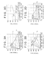
- the front-wheel motor 21 is of a high-rotation and low-torque type as compared with the rear-wheel motor 31. Therefore, in the front-wheel motor 21, the loss caused by iron loss is higher and the loss caused by copper loss is lower than those in the rear-wheel motor 31.
- the "high-rotation and low-torque type" as referred to herein means that the no-load rotation speed of the front-wheel motor 21 is higher than the no-load rotation speed of the rear-wheel motor 31, and the maximum torque Tf of the front-wheel motor 21 is lower than the maximum torque Tb of the rear-wheel motor 31.
- the front-wheel motor 21 has a large loss in a high-rotation region (for example, 7000 rpm to 10,000 rpm) and a low-torque region (for example, 0 N ⁇ m to 10 N ⁇ m) of the motor. Further, the front-wheel motor 21 has a small loss in a low-rotation region (for example, 1500 rpm to 5000 rpm) and a high-torque region (for example, 20 N ⁇ m to 30 N ⁇ m) of the motor. Therefore, the front-wheel motor 21 has a high-efficiency region in the low-rotation region and high-torque region of the motor.
- the rear-wheel motor 31 is a motor of a low-rotation and high-torque type as compared with the front-wheel motor 21. Therefore, in the rear-wheel motor 31, the loss caused by iron loss is lower and the loss caused by copper loss is higher than those in the front-wheel motor 21.
- the "low-rotation and high-torque type" as referred to herein means that the no-load rotation speed of the rear-wheel motor 31 is lower than the no-load rotation speed of the front-wheel motor 21, and the maximum torque Tb of the rear-wheel motor 31 is higher than the maximum torque Tf of the front-wheel motor 21.
- the rear-wheel motor 31 has a large loss in a low-rotation region (for example, 0 rpm to 500 rpm) and a high-torque region (for example, 150 N ⁇ m to 300 N ⁇ m) of the motor. Further, the rear-wheel motor 31 has a small loss in a high-rotation region (for example, 500 rpm to 1000 rpm) and a low-torque region (for example, 50 N ⁇ m to 150 N ⁇ m) of the motor. Therefore, the rear-wheel motor 31 has a high-efficiency region in the high-rotation region and low-torque region of the motor.
- the individual efficiency of the reducer 22 weakly depends on the rotation speed and strongly depends on the torque. The efficiency is higher when the torque is high than when the torque is low because a constant brake drag torque is generated, regardless of the rotation speed, inside the reducer 22. Thus, because of this constant brake drag torque, the ratio of the brake drag torque to the input torque inputted to the reducer 22 increases with the decrease in torque, and the efficiency decreases. This is why the reducer 22 has a high-efficiency region in a high-torque region.
- the rotation speed plotted on the abscissa and the torque plotted on the ordinate in FIG. 2C are the rotation speed and torque after the reduction that are outputted from the reducer 22.
- the combined efficiency of the front-wheel motor 21 and the reducer 22 shown in FIG. 2D can be determined by multiplying the individual efficiency of the front-wheel motor 21 shown in FIG. 2A and the individual efficiency of the reducer 22 shown in FIG. 2C .
- the gear ratio of the reducer 22 (referred to hereinbelow as “reduction ratio RR") is taken as "10".
- the combined characteristic of the front-wheel motor 21 and the reducer 22 is referred to hereinbelow as the characteristic of the front-wheel motor 21 after the reduction.
- the rotation speed region is reduced to one tenth and the torque region becomes tenfold those in the individual characteristic of the front-wheel motor 21 shown in FIG. 2A due to the reduction ratio RR of the reducer 22.
- the efficiency of the front-wheel motor 21 after the reduction has a high-efficiency region in the low-rotation region and high-torque region similarly to the individual efficiency of the front-wheel motor 21. This is because the high-efficiency region (low-rotation region and high-torque region) in the individual efficiency of the front-wheel motor 21 overlaps the high-efficiency region (high-torque region) in the individual efficiency of the reducer 22.
- the front-wheel motor 21 after the reduction and the rear-wheel motor 31 have the following characteristics.
- the rotation speed region of the front-wheel motor 21 after the reduction is the same rotation speed region (0 rpm to 1000 rpm), as compared with the rotation speed region of the rear-wheel motor 31.
- the torque region of the front-wheel motor 21 after the reduction is the same torque region (0 N ⁇ m to 300 N ⁇ m), as compared with the torque region of the rear-wheel motor 31. Therefore, the front-wheel motor 21 after the reduction and the rear-wheel motor 31 have the same respective rotation region in which the motors can rotate and torque region in which the motors can output torque.
- the maximum speed of the vehicle 1 is assumed to be realized at a wheel rotation speed of "1000 rpm" for the front wheels 20 and rear wheels 30.
- the maximum torque Tb of the rear-wheel motor 31 shown in FIG. 2B and the maximum torque Tfr of the front-wheel motor 21 after the reduction shown in FIG. 2D are each "300 N ⁇ m".
- the reduction ratio RR (10) of the reducer 22 is set such that the maximum torque Tf (30 N ⁇ m) of the front-wheel motor 21 becomes equal to the maximum torque Tb (300 N ⁇ m) of the rear-wheel motor 31.
- a value obtained by dividing the maximum torque Tb (300 N ⁇ m) of the rear-wheel motor 31 by the maximum torque Tf (30 N ⁇ m) of the front-wheel motor 21 is the reduction ratio RR (10) of the reducer 22 of the present embodiment.
- the front-wheel motor 21 after the reduction has a low efficiency in the rotation speed region (for example, 500 rpm to 1000 rpm) and torque region (for example, 50 N ⁇ m to 150 N ⁇ m) corresponding to the high-efficiency region of the rear-wheel motor 31.
- the rear-wheel motor 31 has a low efficiency in the rotation speed region (for example, 100 rpm to 500 rpm) and torque region (for example, 200 N ⁇ m to 300 N ⁇ m) corresponding to the high-efficiency region of the front-wheel motor 21 after the reduction. Therefore, there is a difference in the positions of high-efficiency regions at respective rotation speeds and torques between the front-wheel motor 21 after the reduction and the rear-wheel motor 31.
- the total torque at the required vehicle speed is distributed to the front-wheel motor 21 after the reduction and the rear-wheel motor 31, which have different efficiency characteristics, in order to increase the total efficiency of the power system of the vehicle 1.
- the total efficiency of the power system can be also the energy efficiency of the vehicle 1. Further, the total efficiency of the power system can be determined by dividing the power transmitted to the wheels (front wheels 20 and rear wheels 30) by the power consumed by the battery 43. More specifically, the total efficiency of the power system can be defined by the following Eq. (1) to Eq. (3).
- N FR stands for the wheel rotation speed of the front right wheel
- N FL stands for the wheel rotation speed of the front left wheel
- N RR the wheel rotation speed of the rear right wheel
- N RL the wheel rotation speed of the rear left wheel
- T FR stands for the output torque of the front right wheel
- T FL stands for the output torque of the front left wheel
- T RR the output torque of the rear right wheel
- T RL the output torque of the rear left wheel.
- I BAT stands for the battery output current
- V BAT the battery output voltage
- P BAT the battery power consumption
- P V the vehicle drive power
- ⁇ P the total efficiency of the power system.
- the units of rotation speed and torque are “rpm” and “N ⁇ m”, respectively.
- the units of the battery output current, battery output voltage, battery output power and vehicle drive power, and total efficiency are “ampere (A)”, “volt (V)”, “watt (W)", and "%”, respectively.
- SIGN(P BAT ) is a dimensionless value equal to "1" when the battery 43 consumes power and drives the motors 21 and 31 and to "-1" when the motors 21 and 31 are driven and the power is regenerated in the battery 43.
- FIG. 3A is a graph illustrating the total efficiency of the power system related to the vehicle speed and total torque when the optimum torque distribution is performed.
- the combined value of the torque outputted by the wheels (front wheels 20 and rear wheels 30) of four shafts of the vehicle 1 is plotted on the ordinate.
- FIG. 3B shows the distribution ratio of the torque outputted by the front-wheel motor 21 (front wheel 20) after the reduction and the rear-wheel motor 31 (rear wheel 30) when the total efficiency shown in FIG. 3A is obtained.
- the ratio shown in FIG. 3B indicates the distribution ratio for the torque of the front-wheel motor 21 after the reduction in the required torque.
- the distribution ratio is "100%” it means that the required torque is outputted only by the front-wheel motor 21.
- the distribution ratio is "50%" it means that one half of the required torque is outputted by the front-wheel motor 21 after the reduction and the other half is outputted by the rear-wheel motor 31.
- the high-efficiency region of the front-wheel motor 21 after the reduction and the high-efficiency region of the rear-wheel motor 31 are positioned in respectively different rotation speed regions and torque regions. Therefore, the maximization of the total efficiency by torque distribution is facilitated by comparison with the case in which the aforementioned high-efficiency regions are positioned in respectively equal rotation speed regions and torque regions.
- the total efficiency increases in the intermediate-speed region (20 km/h to 60 km/h) and intermediate-torque region (400 N ⁇ m to 800 N ⁇ m), and also in the high-speed region (70 km/h to 100 km/h) and low-torque region (100 N ⁇ m to 250 N ⁇ m).
- the torque is mainly distributed to the front-wheel motor 21 after the reduction that has a high efficiency in the same regions, as shown in FIG. 3B , and in the high-speed region and low-torque region, the torque is mainly distributed to the rear-wheel motor 31 that has a high efficiency in the same regions, as shown in FIG. 3B .
- the wheel speed region corresponding to the rotation speed region of the front-wheel motor 21 after the reduction is "0 km/h to 50 km/h” and the wheel speed region corresponding to the rotation speed region of the rear-wheel motor 31 is "0 km/h to 150 km/h”.
- the front wheels 20 can rotate at a maximum speed of "50 km/h”
- the rear wheels 30 can rotate at a maximum speed of "150 km/h” but where the vehicle 1 runs at a speed equal to or higher than "50 km/h", only the rear-wheel motor 31 is driven.
- the degree of freedom in torque distribution is decreased and the efficient torque distribution is difficult to perform.
- the front-wheel motor 21 after the reduction and the rear-wheel motor 31 have about the same rotation speed region (0 rpm to 1000 rpm).
- the maximum rotation speed of the front-wheel motor 21 after the reduction and the rear-wheel motor 31 is the wheel rotation speed (1000 rpm) corresponding to the maximum speed of the vehicle 1. Therefore, since the vehicle 1 of the present embodiment does not have a speed range in which only any one wheel can rotate, the degree of freedom in torque distribution is high and the efficient torque distribution can be easily performed.
- the torque region of the front-wheel motor 21 after the reduction is "0 N ⁇ m to 50 N ⁇ m” and the torque region of the rear-wheel motor 31 is "0 N ⁇ m to 500 N ⁇ m”
- a torque with a maximum of "100 N ⁇ m” can be outputted on the front wheel 20 side and a torque with a maximum of "1000 N ⁇ m” can be outputted at the rear wheel 30 side.
- a torque with a maximum of" 1100 N ⁇ m” can be outputted for the vehicle 1, but where a torque equal to or higher than "100 N ⁇ m” is required, the rear-wheel motor 31 is surely driven.
- the degree of freedom in torque distribution is decreased and the efficient torque distribution is difficult to perform.
- the front-wheel motor 21 after the reduction and the rear-wheel motor 31 have about the same torque region (0 N.m to 300 N ⁇ m), as can be deduced from FIGS. 2B and 2D .
- the maximum torques Tfr and Tb of the front-wheel motor 21 after the reduction and the rear-wheel motor 31 are about the same (300 N ⁇ m). Therefore, in the vehicle 1 of the present embodiment, the degree of freedom in torque distribution is high and the efficient torque distribution can be easily performed.
- the front-wheel motor 21 after the reduction and the rear-wheel motor 31 are set to have the same rotation speed characteristics and torque characteristics, but different efficiency characteristics with respect to the rotation speed and torque.
- the total efficiency is "equal to or higher than 93%".
- the total torque from the torque (100 N ⁇ m) required for the vehicle 1, is distributed to the rear wheels 30. Therefore, the torque distributed to the front wheels 20 is "0 (zero)" and the front-wheel motor 21 is not driven.
- the reducer 22 and the front-wheel motor 21 are rotated through the front wheels 20 that are rotated by the running vehicle 1.
- part of the torque outputted by the rear-wheel motor 31 is consumed on rotating the front-wheel motor 21 and the reducer 22 and lost. Therefore, in the present embodiment, where the rear-wheel motor 31 is driven, but the front-wheel motor 21 is not driven, the torque is not transmitted to the front-wheel motor 21 and the reducer 22 through the front wheels 20 that are rotated by the running vehicle.
- the torque distribution and total efficiency under the second driving condition DC2 at which the vehicle 1 runs at a low speed (20 km/h) and an intermediate torque (500 N ⁇ m) are explained below.
- the total efficiency is "93%”.
- the total torque, from the torque (500 N ⁇ m) required for the vehicle 1 is distributed to the front wheels 20. Therefore, the torque distributed to the rear wheels 30 is "0 (zero)", and the rear-wheel motor 31 is not driven.
- the rear-wheel motor 31 is rotated through the rear wheels 30 that are rotated by the running vehicle 1.
- the rear wheels 30 are not provided with the reducers 22 and also the iron loss in the rear-wheel motor 31 is comparatively small and the brake drag torque is low, the loss generated by the rotation of the rear-wheel motor 31 is very small.
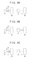
- the clutch of the front wheel 20 is set to the connected state to distribute the entire torque required for the vehicle 1 to the front wheels 20. Further, only the front-wheel motor 21 is driven. Meanwhile, the rear-wheel motor 31 is rotated by the rear wheels 30 rotated by the running vehicle. In this case, the rear-wheel motor 31 may perform regeneration by using the inputted rotation energy, as shown by an arrow in FIG. 4B .
- the torque distribution and total efficiency under the third driving condition DC3 at which the vehicle 1 runs at a high speed (60 km/h) and a high torque (850 N ⁇ m) are described below. As shown in FIG. 3A , under the third driving condition DC3, the total efficiency is "89%". Further, as shown in FIG. 3B , under the third driving condition DC3, 50% (425 N ⁇ m) of the torque (850 N ⁇ m) required for the vehicle 1 is distributed to the front wheels 20, and 50% (425 N ⁇ m) of the torque is distributed to the rear wheels 30.
- the clutches 23 of the front wheels 20 are set to the connected state in order to drive both the front-wheel motor 21 and the rear-wheel motor 31. Further, the front wheels 20 and the rear wheels 30 output an equal torque of "425 N ⁇ m".
- the front-wheel motor 21 and the rear-wheel motor 31 with different positions of high-efficiency regions relating to the rotation speed and torque are controlled according to the driving conditions of the vehicle 1. Further, the total efficiency of the power system is maximized by changing the torque distribution ratio for the front wheels 20 (front-wheel motor 21 after the reduction) and rear wheels 30 (rear-wheel motor 31) according to the running conditions.
- torque (drive power) distribution is explained with respect to the case in which the vehicle 1 accelerates or runs at the same speed, but a similar explanation is applicable to braking power (regenerated power) distribution in the case where the vehicle 1 decelerates.
- braking power regenerated power
- the same approach can be also followed with respect to the front-wheel motor 21 and the rear-wheel motor 31 when determining the braking power distribution at which the regenerated energy can be maximized.
- the effect of the vehicle 1 of the present embodiment is explained below.
- the front-wheel motor 21 after the reduction and the rear-wheel motor 31 have a difference in the efficiency characteristic relating to rotation speed and torque due to respective motor characteristics thereof. Therefore, the torque distribution that increases the total efficiency can be performed in the rotation speed region and torque region that are wider than those in the case of the direct drive system in which all of the wheels (front wheels 20 and rear wheels 30) are directly driven by the motors.
- the reducer 22 is not provided on the rear wheel 30 side, the efficiency on the rear wheel 30 side can be increased accordingly by comparison with the case where all of the wheels (front wheels 20 and rear wheels 30) are driven by the motors through the reducers. Therefore, in the vehicle 1 of the embodiment, the total efficiency of the power system driving the wheels can be increased under various driving conditions.
- the torque region (0 N ⁇ m to 300 N ⁇ m) that can be generated by the front-wheel motor 21 after the reduction is the same as the torque region (0 N ⁇ m to 300 N ⁇ m) that can be generated by the rear-wheel motor 31.
- the torque required for the vehicle 1 can be generated only by either one pair of wheels from among the front wheels 20 and rear wheels 30 driven by the motors 21 and 31, respectively.
- the clutch 23 prohibits the transmission of drive power between the front-wheel motor 21 and the front wheels 20.
- the loss generated as a result of the drive power from the rear-wheel motor 31 rotating the front-wheel motor 21 through the front wheels 20 can be decreased.
- the front-wheel motor 21 driving the front wheel 20 through the reducer 22 is less in size than the rear-wheel motor 31 driving the rear wheel 30. Therefore, the vehicle can be provided with a wider empty space in the radial direction of the motor in the front wheels 20, as compared with the case in which the front wheels 20 are driven by the direct drive system. As a result, the degree of freedom in the arrangement of the steering mechanism 10 on the front wheel 20 side can be increased.
- the abovementioned embodiment may be also changed to the below-descried other embodiments.
- the reduction ratio RR of the reducer 22 may be set from the following Eq. (4) according to the maximum torque Tf of the front-wheel motor 21 and the maximum torque Tb of the rear-wheel motor 31.
- CT is a positive constant; for example, it is preferred that a value thereof be taken within a range of "0.5 to 2.0".
- RR CT ⁇ Tb / Tf
- the reduction ratio RR of the reducer 22 be "5 to 20". In such a case, the torque region of the front-wheel motor 21 after the reduction and the torque region of the rear-wheel motor 31 can be prevented from diverging from each other.
- other torque parameters of the motor such as a rated torque and an initial torque, may be used instead of the maximum torques Tf and Tb.
- the reduction ratio RR of the reducer 22 may be also set from the following Eq. (5) according to the no-load rotation speed (no-load speed) of the front-wheel motor 21 and the no-load rotation speed of the rear-wheel motor 31.
- the no-load rotation speed of the front-wheel motor 21 is denoted by "Nf” and the no-load rotation speed of the rear-wheel motor 31 is denoted by "Nb”.
- CN is a positive constant; for example, it is preferred that a value thereof be taken within a range of "0.5 to 2.0".
- RR CN ⁇ Nf / Nb
- the reduction ratio RR of the reducer 22 be "5 to 20".
- the rotation speed (speed) region of the front-wheel motor 21 after the reduction and the rotation speed region of the rear-wheel motor 31 can be prevented from diverging from each other.
- other rotation speed parameters of the motor such as a rated rotation speed (rated speed) and an initial rotation speed (initial speed), may be used instead of the no-load rotation speed Nf and Nb.
- the reduction ratio RR of the reducer 22 may be such that the reduction ratio RR satisfies either of Eq. (4) and Eq. (5).
- the maximum torque Tfr of the front-wheel motor 21 and the maximum torque Tb of the rear-wheel motor 31 are not necessarily equal to each other.
- the rear-wheel motor 31 be a motor with a rotation speed higher or a torque lower than that of the front-wheel motor 21.
- the clutch 23 may be provided between the rear-wheel motor 31 and the rear wheel 30. It is possible not to provide the clutch 23 between the front-wheel motor 21 and the front wheels 20.
- the front-wheel motor 21 and the rear-wheel motor 31 are not necessarily disposed in each of the front wheels 20 and the rear wheels 30.
- front-wheel motor 21 may be other AC motors such as induction motors.
- the characteristics relating to the rotation speed, torque, and efficiency of the front-wheel motor 21, reducer 22, and rear-wheel motor 31 are not limited to the numerical values in the abovementioned embodiment and may be freely changed.
- Technical concepts that can be grasped from the abovementioned embodiment and other embodiments are additionally described below.
- the reduction ratio of the reducer is preferably set correspondingly, to a value obtained by dividing the no-load rotation speed of the aforementioned one motor by the no-load rotation speed of the other motor.
- the configuration of an electric vehicle 100 is explained below with reference to FIG. 5 .
- the electric vehicle 100 has a pair of front wheels 20 as first wheels, a pair of rear wheels 30 as second wheels, a steering part 4, a vehicle driving device 50, and the battery 43.
- the electric vehicle 100 has a four-wheel drive system such that the vehicle is driven by the drive power of a set of front-wheel driving units 2 and a set of rear-wheel driving units 3 constituting the vehicle driving device 50.
- the front-wheel driving unit 2 is an example of the "first driving unit”
- the rear-wheel driving units 3 is an example of the "second driving unit”.
- Each front wheel 20 has a tire 20A and a wheel 20B.
- Each rear wheel 30 has a tire 30A and a wheel 30B.
- the vehicle driving device 50 has a set of the front-wheel driving units 2, a set of the rear-wheel driving units 3, a control unit 40, and the steering mechanism 10. In the vehicle driving device 50, the front-wheel driving units 2 and the rear-wheel driving units 3 are controlled by the control unit 40.
- the front-wheel driving unit 2 is contained in the wheel 20B of each front wheel 20.
- the front-wheel driving unit 2 has the front-wheel motor 21, the reducer 22, the clutch 23, and a hub unit (not shown in the figure).
- the front-wheel driving unit 2 has a configuration in which front-wheel motor 21 indirectly drives the front wheel 20 through the reducer 22, the clutch 23, and the hub unit.
- the front-wheel motor 21 is an example of the "first drive motor”.
- a three-phase brushless motor of an embedded magnet type is used as the front-wheel motor 21.
- the front-wheel motor 21 has a rotor including a permanent magnet, and a stator configured by winding a conductive wire on a stator core.
- the front-wheel motor 21 is coupled to the reducer 22.
- the reducer 22 uses a planetary gear mechanism.
- the reducer 22 is mounted on the clutch 23.
- the reducer 22 transmits the torque of the front-wheel motor 21 to the wheel 20B through the clutch 23 in a state in which the rotation speed of the front-wheel motor 21 is reduced.
- the clutch 23 is mounted on the wheel 20B, with the hub unit being interposed therebetween.
- the clutch 23 is switched between a connected state in which the torque of the front-wheel motor 21 (reducer 22) can be transmitted to the wheel 20B, and a disconnected state in which the torque of the front-wheel motor 21 (reducer 22) cannot be transmitted to the wheel 20B.
- the rear-wheel driving unit 3 is contained in the wheel 30B of each rear wheel 30.
- the rear-wheel driving unit 3 has the rear-wheel motor 31 and a hub unit.
- the rear-wheel driving unit 3 is configured such that the rear-wheel motor 31 directly drives the rear wheel 30.
- the rear-wheel motor 31 is an example of the "second drive motor”.
- a three-phase brushless motor of an embedded magnet type is used as the rear-wheel motor 31.
- the rear-wheel motor 31 has a rotor including a permanent magnet and a stator configured by winding a conductive wire on a stator core.
- the body of the rear-wheel motor 31 is larger than the combined body of the front-wheel motor 21 and the reducer 22.
- the control unit 40 has the ECU 41 and the inverter 42.
- the control unit 40 is electrically connected to the battery 43. Electric power from the battery 43 is supplied to the control unit 40.
- the ECU 41 is electrically connected to the clutch 23 and the inverter 42.
- the ECU 41 transmits a control signal that controls the operation of the clutch 23 and the inverter 42 to the clutch 23 and the inverter 42. More specifically, the ECU 41 performs switching control of the connected state and disconnected state of the clutch 23 by a clutch control signal.
- the ECU 41 also performs variable control of the rotation speed and torque of the front-wheel motor 21 and the rear-wheel motor 31 by a motor control signal.
- the inverter 42 converts the DC power of the battery 43 into three-phase AC power.
- the inverter 42 supplies the three-phase AC power to the front-wheel motors 21 and the rear-wheel motors 31.
- the inverter 42 can individually change the supply form of the electric power to the front-wheel motors 21 and the rear-wheel motors 31.
- the steering mechanism 10 is connected to the front wheels 20.
- the steering mechanism 10 has the steering shaft 12, the rack shaft 13, the rack-and-pinion mechanism 14, and two tie rods 15.
- One end of the steering shaft 12 is connected to the steering part 4.
- the other end of the steering shaft 12 is connected to the rack shaft 13. Both ends of the rack shaft 13 are connected by the tie rods 15 to the front wheels 20.
- the steering shaft 12 rotates integrally following the rotational operation of the steering part 4.
- the rotation of the steering shaft 12 is converted into the reciprocating movement of the rack shaft 13 by the rack-and-pinion mechanism 14.
- the steering angle of the front wheels 20 is changed through the tie rods 15 by the reciprocating movement of the rack shaft 13.
- the constituent elements of the electric vehicle 100 that are assigned with reference numerals indicate the constituent elements described in FIG. 5 .
- the "motor efficiency" indicates the individual efficiency of the motors 21 and 31. The motor efficiency is calculated on the basis of the power supplied to the motors 21 and 31 and a product of the torque and rotation speed outputted by the motors 21 and 31.
- the front-wheel motor 21 is configured as a motor with a rotation speed higher and a torque lower than those of the rear-wheel motor 31.
- the no-load rotation speed of the front-wheel motor 21 when the same voltage and current are supplied to the motors 21 and 31 is higher than the no-load rotation speed (intersection of broken lines in FIG. 6B ) of the rear-wheel motor 31.
- the maximum torque TF of the front-wheel motor 21 when the same voltage and current are supplied to the motors 21 and 31 is less than the maximum torque TB of the rear-wheel motor 31.
- the upper limit of the rotation speed is set to "7000 rpm" and the maximum torque TF is set to "25 N ⁇ m".
- the front-wheel motor 21 is configured such that the loss caused by iron loss is larger and the loss caused by copper loss is lower than those in the rear-wheel motor 31.
- the iron loss in the front-wheel motor 21 of such a configuration is set to increase by increasing the amount of the permanent magnet, changing the arrangement of the permanent magnet, and increasing the voltage applied to the front-wheel motor 21.
- the copper loss is set to decrease by decreasing the resistance of the conductive wire wound on the stator core and reducing the electric current supplied to the front-wheel motor 21.
- the loss (iron loss) is large in a high-rotation region (for example, 5000 rpm to 7000 rpm) and a low-torque region (for example, 0 N ⁇ m to 5 N ⁇ m) of the front-wheel motor 21.
- the loss (copper loss) is small in a low-rotation region (for example, 500 rpm to 3000 rpm) and a high-torque region (for example, 15 N ⁇ m to 25 N ⁇ m) of the front-wheel motor 21. Therefore, the front-wheel motor 21 has a high motor efficiency in the low-rotation region and high-torque region of the front-wheel motor 21.
- the rear-wheel motor 31 is configured as a motor with a rotation speed lower and a torque higher than those of the front-wheel motor 21.
- the no-load rotation speed of the rear-wheel motor 31 when the same voltage and current are supplied to the motors 21 and 31 is lower than the no-load rotation speed of the front-wheel motor 21.
- the maximum torque TB of the rear-wheel motor 31 when the same voltage and current are supplied to the motors 21 and 31 is larger than the maximum torque TF of the front-wheel motor 21.
- the upper limit of the rotation speed is set to "1000 rpm" and the maximum torque TR is set to "250 N ⁇ m".
- the rear-wheel motor 31 is configured such that the loss caused by iron loss is lower and the loss caused by copper loss is higher than those in the front-wheel motor 21.
- the iron loss is set to decrease by decreasing the amount of the permanent magnet, changing the arrangement of the permanent magnet, and decreasing the voltage applied to the rear-wheel motor 31.
- the copper loss is set to increase by increasing the resistance of the conductive wire wound on the stator core and increasing the electric current supplied to the rear-wheel motor 31.
- the loss (copper loss) is large in a low-rotation region (for example, 0 rpm to 300 rpm) and a high-torque region (for example, 150 N ⁇ m to 250 N ⁇ m) of the rear-wheel motor 31.
- the loss (iron loss) is small in a high-rotation region (for example, 700 rpm to 1000 rpm) and a low-torque region (for example, 50 N ⁇ m to 100 N ⁇ m) of the rear-wheel motor 31. Therefore, the rear-wheel motor 31 has a high motor efficiency in the high-rotation region and low-torque region of the rear-wheel motor 31.
- the individual characteristic of the reducer 22 and the combined characteristic of the front-wheel motor 21 and the reducer 22 are explained below with reference to FIGS. 6C and 6D .
- the individual efficiency of the reducer 22 has weak dependence on the rotation speed outputted by the reducer 22 and a strong dependence on the torque outputted by the reducer 22.
- the individual efficiency of the reducer 22 increases with the increase in the torque outputted by the reducer 22. The reason therefor is explained below.
- a constant brake drag torque is generated regardless of the rotation speed outputted by the reducer 22. Therefore, the ratio of the brake drag torque to the torque outputted by the reducer 22 decreases with the increase in the torque outputted by the reducer 22.
- the individual efficiency of the reducer 22 increases with the increase in the torque outputted by the reducer 22.
- the reduction ratio RR is set to "10".
- the combined characteristic of the front-wheel motor 21 and the reducer 22 shown in FIG. 6D (referred to hereinbelow as "characteristic of front-wheel motor 21 after the reduction") is calculated by multiplying the motor efficiency of the front-wheel motor 21 shown in FIG. 6A and the individual efficiency of the reducer 22 shown in FIG. 6C .
- the rotation speed region is reduced to one tenth and the torque region becomes tenfold those in the individual characteristic of the front-wheel motor 21 shown in FIG. 6A due to the reduction ratio RR.
- the efficiency of the front-wheel motor 21 after the reduction increases in the low-rotation region and high-torque region similarly to the individual efficiency of the front-wheel motor 21. This is because the high-efficiency region in the individual efficiency of the front-wheel motor 21 overlaps the high-efficiency region in the individual efficiency of the reducer 22.
- the front-wheel motor 21 after the reduction and the rear-wheel motor have the following characteristics.
- the upper limit value (700 rpm) of the rotation speed region of the front-wheel motor 21 after the reduction is less than the upper limit value (1000 rpm) of the rotation speed region of the rear-wheel motor 31. Therefore, the upper limit value (700 rpm) of the wheel rotation speed of the wheel 20 driven by the front-wheel motor 21 is less than the upper limit value (1000 rpm) of the wheel rotation speed of the rear wheel 30 driven by the rear-wheel motor 31.
- the electric vehicle 100 of the present embodiment assumes the highest speed when the wheel rotation speed of the front wheels 20 and the rear wheels 30 is "1000 rpm". When the electric vehicle 100 has the highest speed, only the rear-wheel motor 31 is driven.
- the maximum torque TF of the front-wheel motor 21 after the reduction which is shown in FIG. 6D and the maximum torque TB of the rear-wheel motor 31 which is shown in FIG. 6D are each "250 N ⁇ m".
- the reduction ratio RR of the reducer 22 in the present embodiment is set such that the maximum torque TF (250 N ⁇ m) of the front-wheel motor 21 becomes equal to the maximum torque TB (250 N ⁇ m) of the rear-wheel motor 31.
- the reduction ratio RR of the reducer 22 in the present embodiment is calculated as a value obtained by dividing the maximum torque TB of the rear-wheel motor 31 by the maximum torque TF of the front-wheel motor 21.
- the front-wheel motor 21 after the reduction cannot be used in the rotation speed region (700 rpm to 1000 rpm) corresponding to the region with a high motor efficiency of the rear-wheel motor 31.
- the front-wheel motor 21 after the reduction has a low efficiency in the rotation speed region (for example, 400 rpm to 700 rpm) and torque region (for example, 50 N ⁇ m to 150 N ⁇ m) corresponding to the region with a high motor efficiency region of the rear-wheel motor 31.
- the rear-wheel motor 31 has a low efficiency in the rotation speed region (for example, 100 rpm to 300 rpm) and torque region (for example, 150 N ⁇ m to 250 N ⁇ m) corresponding to the region with a high motor efficiency in the front-wheel motor 21 after the reduction. Therefore, there is a difference in the positions of high-efficiency regions at respective rotation speeds and torques between the front-wheel motor 21 after the reduction and the rear-wheel motor 31.
- the control unit 40 of the present embodiment distributes the total torque (total drive power) at the required running speed (vehicle speed) of the electric vehicle 100 to the front-wheel motor 21 after the reduction and the rear-wheel motor 31, which have different efficiency characteristics, in order to increase the total efficiency of the power system of the electric vehicle 100.
- the total efficiency of the power system indicates the energy efficiency of the electric vehicle 100 (vehicle driving device 50).
- the total efficiency of the power system is calculated by dividing the power transmitted to the front wheels 20 and the rear wheels 30 by the power consumed by the battery 43. More specifically, the total efficiency of the power system is calculated by the following Eq. (6), Eq. (7), and to Eq. (8).
- P V 2 ⁇ ⁇ 60 ⁇ N FL ⁇ T FL + N FR ⁇ T FR + N RL ⁇ T RL + N RR ⁇ T RR
- I BAT ⁇ V BAT ⁇ P P V P BAT SIGN P BAT ⁇ 100
- N FR stands for the wheel rotation speed of the front right wheel
- N FL stands for the wheel rotation speed of the front left wheel
- N RR the wheel rotation speed of the rear right wheel
- N RL the wheel rotation speed of the rear left wheel
- T FR stands for the output torque of the front right wheel
- T FL stands for the output torque of the front left wheel
- T RR stands for the output torque of the rear right wheel
- T RL stands for the output torque of the rear left wheel.
- SIGN(P BAT ) is a dimensionless value equal to "1” when the battery 43 consumes power and drives the front-wheel motors 21 and the rear-wheel motors 31 and SIGN(P BAT ) is a dimensionless value equal to "-1" when the electric power is regenerated from the front-wheel motors 21 and the rear-wheel motors 31 in the battery 43.
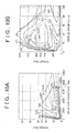
- the total efficiency of the power system is explained below with reference to FIGS. 7A and 7B .
- the graph in FIG. 7A shows how the total efficiency of the power system depends on the vehicle speed and total torque when the optimum torque distribution of the total torque at the vehicle speed of the electric vehicle 100 is performed.
- a vehicle speed (km/h) calculated on the basis of the rotation speed of the front-wheel motor 21 after the reduction and the rear-wheel motor 31 and the diameter of the front wheels 20 and the rear wheels 30 is plotted on the abscissa of the graph shown in FIG. 7A .
- the total torque (N ⁇ m) calculated as a combined value of the torque outputted by the front wheels 20 and the rear wheels 30 is plotted on the ordinate of the graph shown in FIG. 7A .
- the graph in FIG. 7B shows the distribution ratio of the torque outputted by the front-wheel motor 21 after the reduction and the rear-wheel motor 31 when the total efficiency of the power system shown in FIG. 7A is obtained.
- the distribution ratio shown in FIG. 7B indicates the ratio of the output torque of the front-wheel motor 21 after the reduction to the total torque required for the electric vehicle 100 (referred to hereinbelow as "required torque”). More specifically, when the distribution ratio is "100%”, it means that the required torque is outputted only by the front-wheel motor 21 after the reduction. Where the distribution ratio is "50%", it means that one half of the required torque is outputted by the front-wheel motor 21 after the reduction and the other half is outputted by the rear-wheel motor 31. When the distribution ratio is "0%”, the required torque is outputted only by the torque of the rear-wheel motor 31.
- the required torque is calculated, for example, on the basis of the depression amount of the accelerator pedal.
- the distribution ratio increases in the low-speed region to intermediate-speed region (10 km/h to 50 km/h) of the vehicle speed and in the intermediate-torque region (400 N ⁇ m to 800 N ⁇ m) of the total torque.
- the torque is mainly distributed to the front-wheel motor 21 after the reduction that has a high efficiency.
- the distribution ratio decreases in the high-speed region (70 km/h to 100 km/h) of the vehicle speed and the low-torque region (100 N ⁇ m to 250 N ⁇ m) of the total torque:
- the torque is mainly distributed to the rear-wheel motor 31 that has a high efficiency.
- the total power efficiency increases in the low-speed region to intermediate-speed region (10 km/h to 50 km/h) of the vehicle speed and the intermediate-torque region (400 N ⁇ m to 800 N ⁇ m) of the total torque and also in the high-speed region (70 km/h to 100 km/h) of the vehicle speed and the low-torque region (100 N ⁇ m to 250 N ⁇ m) of the total torque, as shown in FIG. 7A .
- Examples of the driving states of the electric vehicle 100 include the first driving state DC1 to fourth driving state DC4 such as shown in FIG. 8 .
- the first driving state DC1 is when the electric vehicle 100 is repeatedly stopped and started, as in the congested traffic or when the electric vehicle 100 is stopped and started at the traffic lights.
- the second driving state DC2 is when the electric vehicle 100 moves up on a steep hill.
- the third driving state DC3 is when the electric vehicle 100 is driven at a high speed on a highway.
- the fourth driving state DC4 is when the electric vehicle 100 is driven in an urban area.
- the electric vehicle 100 In the first driving state DC1, the electric vehicle 100 is driven in the low-speed region of the vehicle speed and the intermediate-torque region of the total torque. In the second driving state DC2, the electric vehicle 100 is driven in the low-speed region of the vehicle speed and the high-torque region of the total torque. In the third driving state DC3, the electric vehicle 100 is driven in the high-speed region of the vehicle speed and the low-torque region of the total torque. In the fourth driving state DC4, the electric vehicle 100 is driven in the intermediate-speed region of the vehicle speed and the low-torque region of the total torque.
- the torque distribution and total power efficiency in the case where the electric vehicle 100 is driven, for example, at a low speed (20 km/h) and an intermediate torque (600 N.m), as the first driving state DC1, are explained below.
- the total power efficiency in the first driving state DC1 is equal to or higher than "93%”.
- the torque (540 N ⁇ m) constituting 90% of the required torque (600 N ⁇ m) is distributed to the front wheels 20, and the torque (60 N ⁇ m) constituting 10% is distributed to the rear wheels 30.
- both the front-wheel motor 21 and the rear-wheel motor 31 are driven. Therefore, the clutch 23 of the front-wheel driving unit 2 is in the connected state.
- the front wheels 20 output a torque of "540 N ⁇ m" and the rear wheels 30 output a torque of "60 N ⁇ m”.
- the torque distribution and total power efficiency in the case where the electric vehicle 100 is driven, for example, at a low speed (20 km/h) and a high torque (900 N ⁇ m), as the second driving state DC2, are explained below.
- the total power efficiency in the second driving state DC2 is equal to or higher than "87%” and lower than "89%”.
- the torque (450 N ⁇ m) constituting 50% of the required torque (900 N ⁇ m) is distributed to the front wheels 20, and the torque (450 N ⁇ m) constituting 50% is distributed to the rear wheels 30.
- both the front-wheel motor 21 and the rear-wheel motor 31 are driven. Therefore, the control unit 40 sets the clutch 23 of the front-wheel driving unit 2 to the connected state.
- the front wheels 20 and the rear wheels 30 output a torque of "450 N ⁇ m".
- the torque distribution and total power efficiency in the case where the electric vehicle 100 is driven, for example, at a high speed (100 km/h) and a low torque (100 N ⁇ m), as the third driving state DC3, are explained below.
- the total power efficiency in the third driving state DC3 is equal to or higher than "93%”.
- the entire required torque (100 N ⁇ m) is distributed to the rear wheels 30.
- the control unit 40 sets the clutch 23 of the front-wheel driving unit 2 to the disconnected state.
- the clutch 23 cuts off the transmission of torque to the front-wheel motor 21 and the reducer 22 through the front wheels 20 rotated by the rotation of the rear wheels 30.
- the clutch 23 inhibits the occurrence of loss caused by the rotation of the front-wheel motor 21 and the reducer 22 caused by the front wheels 20.
- the torque distribution and total power efficiency in the case where the electric vehicle 100 is driven, for example, at an intermediate speed (50 km/h) and an intermediate torque (500 N ⁇ m), as the fourth driving state DC4, are explained below.
- the total power efficiency in the fourth driving state DC4 is equal to or higher than "93%”.
- the entire required torque (500 N ⁇ m) is distributed to the front wheels 20.
- the control unit 40 sets the clutch 23 of the front-wheel driving unit 2 to the connected state.
- the rear wheels 30 are rotated by the running electric vehicle 100. Therefore, the rear-wheel motor 31 is rotated by the rear wheels 30.
- the rear-wheel motor 31 performs regeneration by using the inputted rotation energy as shown by an arrow in FIG. 9C .
- the iron loss is lower than that in the front-wheel motor 21, and therefore the brake drag torque is also lower.
- the rear-wheel motor 31 is not coupled to the reducer. As a result, in the rear-wheel motor 31, the loss generated by the rotation of the rear-wheel motor 31 is less than the loss generated by the rotation of the front-wheel motor 21.
- FIG. 10A the graph of motor efficiency of a motor in which the upper limit value of the rotation speed of the front-wheel motor 21 is assumed to be 10000 rpm (referred to hereinbelow as “comparative motor”) is shown as a comparative example by a broken line.
- the amount of permanent magnet is larger and the voltage applied is lower than those of the comparative motor.
- FIG. 10B the graph of the total power efficiency of the vehicle driving device provided with a comparative motor (referred to hereinbelow as "comparative driving device”) is shown by a broken line.
- a line LE1 indicating the lower limit value of the rotation speed range of a region RE1 in which the motor efficiency of the front-wheel motor 21 of the present embodiment is equal to or higher than "96%” is positioned on the lower rotation speed side in relation to a line LAR1 indicating the lower limit value of the rotation speed range of a region RAR1 in which the motor efficiency of the comparative motor is equal to or higher than "96%”. Therefore, as shown in FIG. 10A , a line LE1 indicating the lower limit value of the rotation speed range of a region RE1 in which the motor efficiency of the front-wheel motor 21 of the present embodiment is equal to or higher than "96%" is positioned on the lower rotation speed side in relation to a line LAR1 indicating the lower limit value of the rotation speed range of a region RAR1 in which the motor efficiency of the comparative motor is equal to or higher than "96%”. Therefore, as shown in FIG.
- a line LE2 indicating the lower limit value of the rotation speed range of a region RE2 in which the motor efficiency of the front-wheel motor 21 after the reduction is equal to or higher than "93%” is positioned on the lower rotation speed side in relation to a line LAR2 indicating the lower limit value of the rotation speed range of a region RAR2 in which the efficiency of the comparative motor is equal to or higher than "93%”.
- the efficiency in the front-wheel motor 21 after the reduction is also positioned on the lower rotation speed side with respect to a motor efficiency of the front-wheel motor 21 of "94%" and "92%".
- the total power efficiency of the comparative driving device is equal to or higher than "91%” and less than "93%", whereas the total power efficiency of the vehicle driving device 50 of the present embodiment is equal to or higher than "93%”.
- the total power efficiency in a lower rotation speed region is increased over that in the comparative driving device. Therefore, in the vehicle driving device 50 of the present embodiment, a high total power efficiency can be provided over a wider rotation speed range than in the comparative driving device.
- the vehicle driving device 50 can have a high total power efficiency when the electric vehicle 100 is driven under traffic congestion conditions, in rural areas, and at a high speed on highways.
- the vehicle driving device 50 of the present embodiment demonstrates the following effects.
- the front-wheel motor 21 is set such that the iron loss in the high-rotation region and high-torque region of the front-wheel motor 21 becomes large and the copper loss in the low-rotation region and high-torque region of the front-wheel motor 21 becomes small.
- the rear-wheel motor 31 is set such that the copper loss in the low-rotation region and high-torque region of the rear-wheel motor 31 becomes large and the iron loss in the high-rotation region and low-torque region of the rear-wheel motor 31 becomes small.
- the upper limit value of the wheel rotation speed of the front wheels 20 driven by the front-wheel motor 21 is less than the upper limit value of the wheel rotation speed of the rear wheels 30 driven by the rear-wheel motor 31.
- the motor efficiency of the front-wheel motor 21 in the low-rotation region and high-torque region of the front-wheel motor 21 increases.
- the motor efficiency of the rear-wheel motor 31 in the high-rotation region and low-torque region of the rear-wheel motor 31 increases.
- the front-wheel motor 21 after the reduction has a higher efficiency in a lower rotation speed region than the configuration in which the upper limit value of the wheel rotation speed of the front wheels 20 driven by the front-wheel motor 21 is assumed to be equal to the upper limit value of the wheel rotation speed of the rear wheels 30 driven by the rear-wheel motor 31. Therefore, in the vehicle driving device 50, the total power efficiency increases in a lower rotation speed region.
- the front-wheel motor 21 after the reduction and the rear-wheel motor 31 differ in the position of a high-efficiency region related to the rotation speed and torque.
- the vehicle driving device 50 makes it possible to perform torque distribution that increases the total efficiency of the power system in a rotation speed region and torque region that are wider than the respective regions in the conventional vehicle driving device.
- the front-wheel driving unit 2 has the front-wheel motor 21 and the reducer 22.
- the steering mechanism 10 is connected to the front wheels 20.
- the maximum torque TF of the front-wheel motor 21 can be decreased by the reducer 22 with respect to that of the configuration in which the front-wheel motor is supposed to drive the front wheels directly (referred to hereinbelow as "virtual driving unit").
- the front-wheel motor 21 can be reduced in body size with respect to the front-wheel motor of the virtual driving unit.
- an empty space formed between the front wheels 20 and the front-wheel motor 21 is larger than that in the virtual driving unit. Therefore, the degree of freedom in arranging the steering mechanism 10 with respect to the front wheels 20 when the steering mechanism 10 is mounted on the front wheels 20 is increased.
- the front-wheel driving unit 2 has the clutch 23.
- the clutch 23 When the entire torque of the required torque is distributed to the rear-wheel motor 31, the clutch 23 is in the disconnected state. With such a configuration, the occurrence of loss caused by the rotation of the front-wheel motor 21 by the torque of the rear-wheel motor 31 through the front wheels 20 can be inhibited.
- the torque region (0 N ⁇ m to 250 N ⁇ m) of the front-wheel motor 21 after the reduction is set to be equal to the torque region (0 N ⁇ m to 250 N ⁇ m) of the rear-wheel motor 31.
- the vehicle driving device and electric vehicle of the invention include embodiments other than the above-described embodiment. Variation examples of the above-described embodiment are presented below as other embodiments of the vehicle driving device and electric vehicle of the invention. The below-described variation examples can be also combined with each other.
- the reduction ratio RR of the reducer 22 of the embodiment is set to "10".
- the setting of the reduction ratio RR is not limited to the contents shown by way of example in the above-described embodiment.
- the reduction ratio RR of the reducer 22 of a variation example is set from the following Eq. (9) on the basis of the maximum torque TF of the front-wheel motor 21 and the maximum torque TB of the rear-wheel motor 31.
- CT is a positive constant.
- RR CT ⁇ TB / TF
- the reduction ratio RR assumes a value between "5" and "20".
- other torque parameters of the motors 21 and 31, such as a rated torque and an initial torque may be used instead of the maximum torques TF and TB.
- the maximum torque TF of the front-wheel motor 21 and the maximum torque TB of the rear-wheel motor 31 can have mutually different values.
- a three-phase brushless motor of an embedded magnet type is used as the front-wheel motor 21 of the embodiment.
- the configuration of the front-wheel motor 21 is not limited to the contents disclosed by way of example in the embodiment.
- a three-phase brushless motor of a surface magnet type can be used as the front-wheel motor 21 of a variation example.
- An AC motor of another configuration, such as an induction motor, can be used as the front-wheel motor 21 of another variation example. The same changes can be made with respect to the rear-wheel motor 31.
- the clutch 23 can be omitted.
- the reducer 22 can be also omitted.
- the upper limit value of the wheel rotation speed of the front wheels 20 driven by the front-wheel motor 21 is set to a value that is less than the wheel rotation speed of the rear wheels 30 driven by the rear-wheel motor 31, such as "700 rpm".
- the clutch 23 can be also added to the rear-wheel driving unit 3 of the embodiment.
- a reducer can be also added to the rear-wheel driving unit 3 of the embodiment.
- the reduction ratio of the reducer of the rear-wheel driving unit 3 is preferably less than the reduction ratio of the reducer 22.
- the front-wheel driving unit 2 of the embodiment has a configuration in which each front-wheel motor 21 directly drives the respective front wheel 20.
- the configuration of the front-wheel driving unit 2 is not limited to the contents disclosed by way of example in the embodiment.
- the front-wheel driving unit 2 of a variation example has a drive shaft connecting the front wheels 20 to each other, and a drive motor rotating the drive shaft In the front-wheel driving unit 2 of the variation example, the motor rotates the drive shaft, thereby rotating the front wheels 20.
- the rear-wheel driving unit 3 can be changed in a similar manner.
- the vehicle driving device 50 of the embodiment has a steering mechanism 10.
- the configuration of the vehicle driving device 50 is not limited to the contents disclosed by way of example in the embodiment.
- the vehicle driving device 50 of a variation example does not have the steering mechanism 10.
- the electric vehicle 100 of a variation example has the steering mechanism 10.
- the vehicle driving device 50 of the embodiment uses a motor of a high-rotation low-torque type as the front-wheel motor 21 and a motor of a low-rotation high-torque type as the rear-wheel motor 31.
- the motor characteristics of the motors 21 and 31 are not limited to the contents disclosed by way of example in the embodiment.
- a motor of a low-rotation high torque is used as the front-wheel motor 21, and a motor of a high-rotation low-torque type is used as the rear-wheel motor 31.
- the reducer 22 and the clutch 23 are omitted from the front-wheel driving unit 2, and the reducer 22 and the clutch 23 are added to the rear-wheel driving unit 3.
- the graphs of the characteristics relating to the rotation speed, torque, and motor efficiency of the front-wheel motor 21, the reducer 22, and the rear-wheel motor 31 are not limited to the graphs (see FIGS. 6A to 9C ) presented in the embodiment.
- the graphs of the characteristics relating to the rotation speed, torque, and motor efficiency of the front-wheel motor 21 and the reducer 22 can be freely changed with consideration for providing the front-wheel motor 21 with the increased iron loss in the high-rotation region and low-torque region and decreased copper loss in the low-rotation region and high-torque region of the front-wheel motor 21.
- the graphs of the characteristics relating to the rotation speed, torque, and motor efficiency of the rear-wheel motor 31 can be freely changed with consideration for providing the rear-wheel motor 31 with the increased copper loss in the low-rotation region and high-torque region and decreased iron loss in the high-rotation region and low-torque region of the rear-wheel motor 31.
Abstract
Description
- The invention relates to a vehicle in which wheels are driven by motors, such as an electric automobile.
- The invention also relates to a vehicle driving device provided with drive motors that drive first wheels and second wheels, respectively, and to an electric vehicle equipped with the vehicle driving device.
- Electric vehicles using an in-wheel motor system in which a motor driving a wheel is disposed inside the wheel have been disclosed. Among them, there are electric vehicles using a direct drive system by which a wheel is driven by a motor directly connected to the wheel (see, for example, Japanese Patent Application Publication No.
2011-188557 JP 2011-188557 A - In such an electric vehicle, a torque necessary when the vehicle is driven is distributed to front-wheel motors driving the front wheels and rear-wheel motors driving the rear wheels in order to minimize the total power consumed by all of the motors. Thus, in the electric vehicle, the torque that can be efficiently outputted by the front-wheel motors is combined with the torque that can be efficiently outputted by the rear-wheel motors to output the torque necessary when the vehicle is driven.
- A vehicle driving device has a configuration in which two first drive motors that drive a pair of respective first wheels and two second drive motors that drive a pair of respective second wheels are contained in respective first wheels and second wheels. The vehicle driving device distributes the torque when the electric vehicle is driven to the first drive motors and second drive motors so that the total power consumed by all of the drive motors is minimized. Thus, the vehicle driving device combines the torque at which the individual efficiency of the first drive motor is increased and the torque at which the individual efficiency of the second drive motor is increased to output the torque necessary when the electric vehicle is driven.
JP 2011-188557 A - However, since the electric vehicle disclosed in
JP 2011-188557 A - Therefore, it is possible that at a certain speed of the running vehicle, the required torque could not be outputted with the torque that can be efficiently outputted by the front-wheel motors and rear-wheel motors. Thus, a problem associated with the abovementioned electric vehicles is that driving conditions at which the total efficiency of the power system can be increased are restricted to a narrow range.
- This problem is generally common to vehicles in which a plurality of wheels are driven by a plurality of motors. The invention provides a vehicle in which the total efficiency of the power system that drives the wheels can be increased.
- In the vehicle driving device described in
JP 2011-188557 A - The invention also provides a vehicle driving device that can inhibit the decrease in the total efficiency of the power system in a low-rotation region and an electric vehicle equipped with the vehicle driving device.
- The means of the invention and the operation effects thereof are described below. According to a first aspect of the invention, a vehicle includes a pair of front wheels; a pair of rear wheels; a front-wheel motor configured to drive the front wheels; a rear-wheel motor configured to drive the rear wheels; and a reducer configured to reduce a rotation speed of one of the front-wheel motor and the rear-wheel motor and transmit drive power to the wheels driven by the one motor, wherein one of the front-wheel motor and the rear-wheel motor is a motor with a rotation speed higher and torque lower than those of the other one of the motors.
- According to the abovementioned aspect, one of the front-wheel motor and the rear-wheel motor is a motor with a rotation speed higher and torque lower than those of the other one of the motors. Further, the other one the motors is a motor with a rotation speed lower and a torque higher than those of the one of the motors. Thus, in the one of the motors, the loss (iron loss) in the high-rotation region and low-torque region of the motor is large, and the loss (copper loss) in the low-rotation region and high-torque region of the motor is low. In the other one the motors, the loss (copper loss) in the low-rotation region and high-torque region of the motor is large, and the loss (iron loss) in the high-rotation region and low-torque region of the motor is low.
- Therefore, the one of the motors and the other one of the motors have high-efficiency regions in mutually different rotation speed regions and torque regions. The one of the motors has an efficiency characteristic such that even after the reduction with the reducer, the loss in the high-rotation region and low-torque region is higher and the loss in the low-rotation region and high-torque region is lower than those in the other one the motors.
- Thus, the one of the motors subjected to reduction with the reducer is easy to provide with a difference in the efficiency characteristic related to rotation speed and torque as compared with the other one the motors that is not subjected to reduction with the reducer. For this reason, torque distribution that increases the total efficiency of the power system can be performed in a rotation speed region and a torque region that are wider than those in the case where all of the wheels (front wheels and rear wheels) are directly driven by the motors. Therefore, in the vehicle of the abovementioned configuration, the total efficiency of the power system driving the wheels can be increased under various driving conditions.
- The expression "one of the motors has a rotation speed higher and a torque lower than those of the other one the motors" means that the no-load rotation speed of the one of the motors is higher than the no-load rotation speed of the other one the motors, and the maximum torque of the one of the motors is lower than the maximum torque of the other one the motors.
- In the vehicle according to the abovementioned aspect, a reduction ratio of the reducer may be set according to a value obtained by dividing a maximum torque of the other one the motors by a maximum torque of the one of the motors. With such a feature, the torque region that can be generated by the one of the motors reduced by the reducer can be prevented from diverging from the torque region that can be generated by the other one the motors. As a result, for example, it is possible to avoid the case in which the torque required for the vehicle can be generated only by the one of the motors reduced by the reducer or the other one the motors which is not reduced by the reducer.
- The vehicle according to the abovementioned aspect may further include a clutch configured to allow or prohibit the transmission of drive power between the one of the motors and the wheels driven by the one of the motors. With such a configuration, where the drive power is distributed only to the other one the motors when the vehicle is driven, the clutch prohibits the transmission of drive power between the one of the motors and the wheels driven by the one of the motors. As a result, the loss generated when the drive power produced by the other one the motors rotates the one of the motors through the wheels driven by the one of the motors can be reduced.
- The vehicle according to the abovementioned aspect may be by further provided on a front wheel side with a steering mechanism for changing a traveling direction, wherein the one motor is the front-wheel motor, and the other one the motors is the rear-wheel motor.
- In general, when it is desired to increase the torque outputted by a motor, the motor body is radially enlarged to increase the number of windings of the motor. Thus, the body of the rear-wheel motor is enlarged to output a high torque, as compared with the front-wheel motor.
- With the above-described configuration, the front wheels are driven by the front-wheel motor via the reducer. Meanwhile, the rear wheels are directly driven by the rear-wheel motor which is larger in body size than the front-wheel motor. Therefore, the vehicle can be provided with a wider empty space in the radial direction of the motor in the front wheel, as compared with the case in which the front wheels are driven by the rear-wheel motor. As a result, the degree of freedom in the arrangement of a steering mechanism when it is provided on the front wheel side can be increased.
- According to the abovementioned aspect, the total efficiency of the power system driving the wheels can be increased.
- According to a second aspect of the invention, a vehicle driving device includes: a first driving unit having a first drive motor driving first wheels; and a second driving unit having a second drive motor driving second wheels. The first drive motor is set such that an iron loss is larger than an iron loss of the second drive motor in a high-rotation region and a low-torque region of the first drive motor, and a copper loss is smaller than a copper loss of the second drive motor in a low-rotation region and a high-torque region of the first drive motor. The second drive motor is set such that a copper loss is larger than a copper loss of the first drive motor in a low-rotation region and a high-torque region of the second drive motor, and an iron loss is smaller than an iron loss of the first drive motor in a high-rotation region and a low-torque region of the second drive motor. An upper limit value of a wheel rotation speed of the first wheels driven by the first drive motor is less than an upper limit value of a wheel rotation speed of the second wheels driven by the second drive motor.
- According to the abovementioned aspect, the motor efficiency increases in the low-rotation region and high-torque region of the first drive motor. Therefore, the motor efficiency increases in the low-rotation region, as compared with the conventional vehicle driving device. In addition, the upper limit value of the wheel rotation speed of the first wheels driven by the first drive motor is less than the upper limit value of the wheel rotation speed of the second wheels driven by the second drive motor. For this reason, in the present vehicle driving device, the motor efficiency in the lower-rotation region increases over than in the case in which the upper limit value of the wheel rotation speed of the first wheels driven by the first drive motor is assumed to be equal to the upper limit value of the wheel rotation speed of the second wheels driven by the second drive motor. Therefore, in the present vehicle driving device, the total power efficiency in the lower-rotation region is increased.
- The vehicle driving device according to the abovementioned aspect may further include a reducer configured to transmit a torque of the first drive motor to the first wheels in a state in which a rotation speed of the first drive motor is reduced. Further, in this configuration, the first wheels may be front wheels, the second wheels may be rear wheels, and the vehicle driving device may further include a steering mechanism configured to change a steering angle of the front wheels.
- The number of windings (number of turns) of a conductive wire in a drive motor is typically increased when the torque outputted by the drive motor is increased. In this case, a space is necessary for inserting the conductive wire into the slots of the stator core onto which the conductive wire is wound. Therefore, the stator core is enlarged in the radial direction of the drive motor. As a result, the drive motor is radially enlarged.
- Meanwhile, since the reducer is connected to the first drive motor, when the maximum torque of the first drive motor after the reduction and the maximum torque of a virtual drive motor that is assumed to drive the first wheels (front wheels) directly are equal to each other, the individual maximum torque of the first drive motor becomes less than the maximum torque of the virtual drive motor. Therefore, the first drive motor is less in the body size than the virtual drive motor.
- In the abovementioned configuration, since the first drive motor drives the front wheels, an empty space formed between the front wheels and the first drive motor can be made wider than in the configuration in which the virtual drive motor drives the front wheels. Therefore, when a steering mechanism is mounted on the front wheels, the degree of freedom in arranging the steering mechanism relative to the front wheels is increased.
- In the vehicle driving device according to the abovementioned aspect, the first driving unit may be further provided with a clutch that switches between a connected state in which a torque of the first drive motor can be transmitted to the first wheels, and a disconnected state in which the torque of the first drive motor cannot be transmitted to the first wheels.
- Further, in the abovementioned configuration, when only the second drive motor is driven, the clutch may be in the disconnected state. In such a configuration, when the torque necessary to drive the electric vehicle is distributed only to the second drive motor, the transmission of torque between the first wheels and the first drive motor is cut off by the clutch. As a result, the occurrence of loss caused by the rotation of the first drive motor through the first wheels by the torque generated by the second drive motor is inhibited.
- In the above-described aspect, the electric vehicle may be equipped with the vehicle driving device.
- With the vehicle driving device and electric vehicle according to the above-described aspects, the decrease in the total efficiency of the power system in a low-rotation region can be inhibited.
- Features, advantages, and technical and industrial significance of exemplary embodiments of the invention will be described below with reference to the accompanying drawings, in which like numerals denote like elements, and wherein:
-
FIG. 1 is a schematic drawing illustrating the general configuration of the vehicle of an embodiment; -
FIG. 2A is a graph showing the individual efficiency of a front-wheel motor; -
FIG. 2B is a graph showing the individual efficiency of a rear-wheel motor; -
FIG. 2C is a graph showing the individual efficiency of a reducer; -
FIG. 2D is a graph showing the combined efficiency of the front-wheel motor and reducer; -
FIG. 3A is a graph showing the total efficiency of a power system; -
FIG. 3B is a graph showing a torque distribution ratio; -
FIG. 4A is a schematic diagram showing the pattern of torque distribution corresponding to the driving conditions of the vehicle; -
FIG. 4B is a schematic diagram showing the pattern of torque distribution corresponding to the driving conditions of the vehicle; -
FIG. 4C is a schematic diagram showing the pattern of torque distribution corresponding to the driving conditions of the vehicle; -
FIG. 5 is a schematic diagram of an electric vehicle equipped with the vehicle driving device of the embodiment; -
FIG. 6A is a graph showing the individual efficiency of a front-wheel drive motor, this graph relating to the vehicle driving device of the embodiment; -
FIG. 6B is a graph showing the individual efficiency of a rear-wheel drive motor, this graph relating to the vehicle driving device of the embodiment; -
FIG. 6C is a graph showing the individual efficiency of a reducer, this graph relating to the vehicle driving device of the embodiment; -
FIG. 6D is a graph showing the combined efficiency obtained by combining the individual efficiency of the front-wheel drive motor and the individual efficiency of the reducer, this graph relating to the vehicle driving device of the embodiment; -
FIG. 7A is a graph showing the total efficiency of the power system, this graph relating to the vehicle driving device of the embodiment; -
FIG. 7B is a graph showing the torque distribution ratio, this graph relating to the vehicle driving device of the embodiment; -
FIG. 8 is a graph showing schematically the rotation speed region and torque region in the running state of the electric vehicle of the embodiment; -
FIG. 9A is a plan view illustrating schematically the state of the front wheels and rear wheels corresponding to the running state of the electric vehicle of the embodiment; -
FIG. 9B is a plan view illustrating schematically the state of the front wheels and rear wheels corresponding to the running state of the electric vehicle of the embodiment; -
FIG. 9C is a plan view illustrating schematically the state of the front wheels and rear wheels corresponding to the running state of the electric vehicle of the embodiment; -
FIG. 10A is a graph showing the individual efficiency of the front-wheel drive motor, this graph relating to the vehicle driving device of the embodiment; and -
FIG. 10B is a graph showing the total efficiency of the power system, this graph relating to the vehicle driving device of the embodiment. - An embodiment of the invention will be explained hereinbelow with reference to the appended drawings. As shown in
FIG. 1 , avehicle 1 is provided with asteering mechanism 10, a pair of left and rightfront wheels 20, a pair of left and rightrear wheels 30, anECU 41, aninverter 42, and abattery 43. - The
steering mechanism 10 has asteering wheel 11, a steeringshaft 12, arack shaft 13, a rack-and-pinion mechanism 14, and twotie rods 15. In thesteering mechanism 10, the steeringshaft 12 rotates following the rotation of thesteering wheel 11. The rotation of the steeringshaft 12 is converted by the rack-and-pinion mechanism 14 into the reciprocating movement of therack shaft 13, whereby the steering angle of thefront wheels 20 is changed. - The
front wheel 20 has a front-wheel motor 21, areducer 22, and a clutch 23. The front-wheel motor 21 is, for example, an alternate current (AC) motor such as a synchronous motor. Further, the front-wheel motor 21 drives thefront wheel 20 through thereducer 22 and the clutch 23. Thereducer 22 reduces the rotation speed of the front-wheel motor 21 and transmits the reduced rotation speed to thefront wheel 20. The rotation speed of thefront wheel 20 is determined by dividing the rotation speed of the front-wheel motor 21 by the gear ratio of thereducer 22. The clutch 23 is provided between thereducer 22 and thefront wheel 20. The clutch 23 allows or prohibits the transmission of drive power between the front-wheel motor 21 and thefront wheel 20. In this case, the state of the clutch 23 in which the transmission of drive power between the front-wheel motor 21 and thefront wheel 20 is allowed is referred to as "connected state", and the state in which the transmission of drive power is prohibited is referred to as "disconnected state". The front-wheel motor 21, thereducer 22, and the clutch 23 are contained in thefront wheel 20. In this respect, thefront wheel 20 constitutes the so-called in-wheel motor. - The
rear wheel 30 has a rear-wheel motor 31. The rear-wheel motor 31 is an AC motor such as a synchronous motor, similarly to the front-wheel motor 21. The rear-wheel motor 31 directly drives therear wheel 30. Therefore, the rotation speed of therear wheel 30 is equal to the rotation speed of the rear-wheel motor 31. Further, the rear-wheel motor 31 is contained in therear wheel 30. In this respect, therear wheel 30 constitutes an in-wheel motor of the so-called direct drive system. Since the rear-wheel motor 31 directly drives therear wheel 30, it is larger in the body size than the combination of the front-wheel motor 21 and thereducer 22. - The
inverter 42 converts the electric power stored in thebattery 43 from a direct current (DC) current to a three-phase AC current and supplies the converted power to the front-wheel motor 21 and the rear-wheel motor 31. Theinverter 42 can change individually the supply mode of the electric power to the front-wheel motor 21 and the rear-wheel motor 31. - An electronic control unit (ECU) 41 is electrically connected to the clutch 23 and the
inverter 42. TheECU 41 transmits a control signal to the clutch 23 and theinverter 42 and controls the operation of the clutch 23 and theinverter 42. Thus, theECU 41 performs switching control of the connected state and disconnected state of the clutch 23. TheECU 41 also performs variable control of the rotation speed and torque of the front-wheel motor 21 and the rear-wheel motor 31 through theinverter 42. - Characteristics of the front-
wheel motor 21 and the rear-wheel motor 31 are explained below, As shown inFIGS. 2A and 2B , the front-wheel motor 21 is of a high-rotation and low-torque type as compared with the rear-wheel motor 31. Therefore, in the front-wheel motor 21, the loss caused by iron loss is higher and the loss caused by copper loss is lower than those in the rear-wheel motor 31. The "high-rotation and low-torque type" as referred to herein means that the no-load rotation speed of the front-wheel motor 21 is higher than the no-load rotation speed of the rear-wheel motor 31, and the maximum torque Tf of the front-wheel motor 21 is lower than the maximum torque Tb of the rear-wheel motor 31. - Thus, as shown in
FIG. 2A , the front-wheel motor 21 has a large loss in a high-rotation region (for example, 7000 rpm to 10,000 rpm) and a low-torque region (for example, 0 N·m to 10 N·m) of the motor. Further, the front-wheel motor 21 has a small loss in a low-rotation region (for example, 1500 rpm to 5000 rpm) and a high-torque region (for example, 20 N·m to 30 N·m) of the motor. Therefore, the front-wheel motor 21 has a high-efficiency region in the low-rotation region and high-torque region of the motor. - As shown in
FIGS. 2A and 2B , the rear-wheel motor 31 is a motor of a low-rotation and high-torque type as compared with the front-wheel motor 21. Therefore, in the rear-wheel motor 31, the loss caused by iron loss is lower and the loss caused by copper loss is higher than those in the front-wheel motor 21. The "low-rotation and high-torque type" as referred to herein means that the no-load rotation speed of the rear-wheel motor 31 is lower than the no-load rotation speed of the front-wheel motor 21, and the maximum torque Tb of the rear-wheel motor 31 is higher than the maximum torque Tf of the front-wheel motor 21. - Thus, as shown in
FIG. 2B , the rear-wheel motor 31 has a large loss in a low-rotation region (for example, 0 rpm to 500 rpm) and a high-torque region (for example, 150 N·m to 300 N·m) of the motor. Further, the rear-wheel motor 31 has a small loss in a high-rotation region (for example, 500 rpm to 1000 rpm) and a low-torque region (for example, 50 N·m to 150 N·m) of the motor. Therefore, the rear-wheel motor 31 has a high-efficiency region in the high-rotation region and low-torque region of the motor. - In the region with an efficiency equal to or lower than "88%" in
FIG. 2A and the region with an efficiency equal to or lower than "88%" inFIG. 2B , the efficiency actually greatly changes in the direction of reduction; this is not shown in the figures to simplify the figures. The same is true for the region with an efficiency equal to or lower than "88%" inFIG. 2C and the region with an efficiency equal to or lower than "84%" inFIG. 2D , which are described hereinbelow. - Individual characteristics of the
reducer 22 that reduces the rotation speed of the front-wheel motor 21 and combined characteristics of the front-wheel motor 21 and thereducer 22 are explained below. As shown inFIG. 2C , the individual efficiency of thereducer 22 weakly depends on the rotation speed and strongly depends on the torque. The efficiency is higher when the torque is high than when the torque is low because a constant brake drag torque is generated, regardless of the rotation speed, inside thereducer 22. Thus, because of this constant brake drag torque, the ratio of the brake drag torque to the input torque inputted to thereducer 22 increases with the decrease in torque, and the efficiency decreases. This is why thereducer 22 has a high-efficiency region in a high-torque region. The rotation speed plotted on the abscissa and the torque plotted on the ordinate inFIG. 2C are the rotation speed and torque after the reduction that are outputted from thereducer 22. - The combined efficiency of the front-
wheel motor 21 and thereducer 22 shown inFIG. 2D can be determined by multiplying the individual efficiency of the front-wheel motor 21 shown inFIG. 2A and the individual efficiency of thereducer 22 shown inFIG. 2C . In the present embodiment, the gear ratio of the reducer 22 (referred to hereinbelow as "reduction ratio RR") is taken as "10". Further, the combined characteristic of the front-wheel motor 21 and thereducer 22 is referred to hereinbelow as the characteristic of the front-wheel motor 21 after the reduction. - As shown in
FIG. 2D , in the characteristic of the front-wheel motor 21 after the reduction, the rotation speed region is reduced to one tenth and the torque region becomes tenfold those in the individual characteristic of the front-wheel motor 21 shown inFIG. 2A due to the reduction ratio RR of thereducer 22. The efficiency of the front-wheel motor 21 after the reduction has a high-efficiency region in the low-rotation region and high-torque region similarly to the individual efficiency of the front-wheel motor 21. This is because the high-efficiency region (low-rotation region and high-torque region) in the individual efficiency of the front-wheel motor 21 overlaps the high-efficiency region (high-torque region) in the individual efficiency of thereducer 22. - Accordingly, the front-
wheel motor 21 after the reduction and the rear-wheel motor 31 have the following characteristics. Thus, the rotation speed region of the front-wheel motor 21 after the reduction is the same rotation speed region (0 rpm to 1000 rpm), as compared with the rotation speed region of the rear-wheel motor 31. Further, the torque region of the front-wheel motor 21 after the reduction is the same torque region (0 N·m to 300 N·m), as compared with the torque region of the rear-wheel motor 31. Therefore, the front-wheel motor 21 after the reduction and the rear-wheel motor 31 have the same respective rotation region in which the motors can rotate and torque region in which the motors can output torque. In the present embodiment, the maximum speed of thevehicle 1 is assumed to be realized at a wheel rotation speed of "1000 rpm" for thefront wheels 20 andrear wheels 30. - Further, the maximum torque Tb of the rear-
wheel motor 31 shown inFIG. 2B and the maximum torque Tfr of the front-wheel motor 21 after the reduction shown inFIG. 2D are each "300 N·m". This is because in the present embodiment, the reduction ratio RR (10) of thereducer 22 is set such that the maximum torque Tf (30 N·m) of the front-wheel motor 21 becomes equal to the maximum torque Tb (300 N·m) of the rear-wheel motor 31. Thus, a value obtained by dividing the maximum torque Tb (300 N·m) of the rear-wheel motor 31 by the maximum torque Tf (30 N·m) of the front-wheel motor 21 is the reduction ratio RR (10) of thereducer 22 of the present embodiment. - The front-
wheel motor 21 after the reduction has a low efficiency in the rotation speed region (for example, 500 rpm to 1000 rpm) and torque region (for example, 50 N·m to 150 N·m) corresponding to the high-efficiency region of the rear-wheel motor 31. Further, the rear-wheel motor 31 has a low efficiency in the rotation speed region (for example, 100 rpm to 500 rpm) and torque region (for example, 200 N·m to 300 N·m) corresponding to the high-efficiency region of the front-wheel motor 21 after the reduction. Therefore, there is a difference in the positions of high-efficiency regions at respective rotation speeds and torques between the front-wheel motor 21 after the reduction and the rear-wheel motor 31. In the present embodiment, the total torque at the required vehicle speed is distributed to the front-wheel motor 21 after the reduction and the rear-wheel motor 31, which have different efficiency characteristics, in order to increase the total efficiency of the power system of thevehicle 1. - The total efficiency of the power system can be also the energy efficiency of the
vehicle 1. Further, the total efficiency of the power system can be determined by dividing the power transmitted to the wheels (front wheels 20 and rear wheels 30) by the power consumed by thebattery 43. More specifically, the total efficiency of the power system can be defined by the following Eq. (1) to Eq. (3). - In the equations, "NFR" stands for the wheel rotation speed of the front right wheel, "NFL" - the wheel rotation speed of the front left wheel, "NRR" - the wheel rotation speed of the rear right wheel, and "NRL" - the wheel rotation speed of the rear left wheel. "TFR" stands for the output torque of the front right wheel, "TFL" - the output torque of the front left wheel, "TRR" - the output torque of the rear right wheel, and "TRL" - the output torque of the rear left wheel. Further, "IBAT" stands for the battery output current, "VBAT" - the battery output voltage, "PBAT" - the battery power consumption, "PV" - the vehicle drive power, and "ηP" - the total efficiency of the power system. The units of rotation speed and torque are "rpm" and "N·m", respectively. The units of the battery output current, battery output voltage, battery output power and vehicle drive power, and total efficiency are "ampere (A)", "volt (V)", "watt (W)", and "%", respectively.


- SIGN(PBAT) is a dimensionless value equal to "1" when the
battery 43 consumes power and drives themotors motors battery 43. - The total efficiency of the power system of the
vehicle 1 is explained below with reference toFIGS. 3A and 3B. FIG. 3A is a graph illustrating the total efficiency of the power system related to the vehicle speed and total torque when the optimum torque distribution is performed. A wheel speed (= vehicle speed) corresponding to the wheel diameter and the rotation speed of the front-wheel motor 21 after the reduction and the rear-wheel motor 31 is plotted on the abscissa of the graph. The combined value of the torque outputted by the wheels (front wheels 20 and rear wheels 30) of four shafts of thevehicle 1 is plotted on the ordinate.FIG. 3B shows the distribution ratio of the torque outputted by the front-wheel motor 21 (front wheel 20) after the reduction and the rear-wheel motor 31 (rear wheel 30) when the total efficiency shown inFIG. 3A is obtained. The ratio shown inFIG. 3B indicates the distribution ratio for the torque of the front-wheel motor 21 after the reduction in the required torque. Thus, where the distribution ratio is "100%", it means that the required torque is outputted only by the front-wheel motor 21. Meanwhile, where the distribution ratio is "50%", it means that one half of the required torque is outputted by the front-wheel motor 21 after the reduction and the other half is outputted by the rear-wheel motor 31. - Thus, in the present embodiment the high-efficiency region of the front-
wheel motor 21 after the reduction and the high-efficiency region of the rear-wheel motor 31 are positioned in respectively different rotation speed regions and torque regions. Therefore, the maximization of the total efficiency by torque distribution is facilitated by comparison with the case in which the aforementioned high-efficiency regions are positioned in respectively equal rotation speed regions and torque regions. - As shown in
FIG. 3A , the total efficiency increases in the intermediate-speed region (20 km/h to 60 km/h) and intermediate-torque region (400 N·m to 800 N·m), and also in the high-speed region (70 km/h to 100 km/h) and low-torque region (100 N·m to 250 N·m). This is because in the intermediate-speed region and intermediate-torque region, the torque is mainly distributed to the front-wheel motor 21 after the reduction that has a high efficiency in the same regions, as shown inFIG. 3B , and in the high-speed region and low-torque region, the torque is mainly distributed to the rear-wheel motor 31 that has a high efficiency in the same regions, as shown inFIG. 3B . - Let us assume the case in which the wheel speed region corresponding to the rotation speed region of the front-
wheel motor 21 after the reduction is "0 km/h to 50 km/h" and the wheel speed region corresponding to the rotation speed region of the rear-wheel motor 31 is "0 km/h to 150 km/h". In this case, thefront wheels 20 can rotate at a maximum speed of "50 km/h", and therear wheels 30 can rotate at a maximum speed of "150 km/h", but where thevehicle 1 runs at a speed equal to or higher than "50 km/h", only the rear-wheel motor 31 is driven. Therefore, where the rotation speed regions of the front-wheel motor 21 after the reduction and the rear-wheel motor 31 diverge from each other, as indicated hereinabove, the degree of freedom in torque distribution is decreased and the efficient torque distribution is difficult to perform. By contrast, in the present embodiment, the front-wheel motor 21 after the reduction and the rear-wheel motor 31 have about the same rotation speed region (0 rpm to 1000 rpm). Furthermore, the maximum rotation speed of the front-wheel motor 21 after the reduction and the rear-wheel motor 31 is the wheel rotation speed (1000 rpm) corresponding to the maximum speed of thevehicle 1. Therefore, since thevehicle 1 of the present embodiment does not have a speed range in which only any one wheel can rotate, the degree of freedom in torque distribution is high and the efficient torque distribution can be easily performed. - Further, where the torque region of the front-
wheel motor 21 after the reduction is "0 N·m to 50 N·m" and the torque region of the rear-wheel motor 31 is "0 N·m to 500 N·m", a torque with a maximum of "100 N·m" can be outputted on thefront wheel 20 side and a torque with a maximum of "1000 N·m" can be outputted at therear wheel 30 side. Further, a torque with a maximum of" 1100 N·m" can be outputted for thevehicle 1, but where a torque equal to or higher than "100 N·m" is required, the rear-wheel motor 31 is surely driven. Therefore, when the torque regions of the front-wheel motor 21 after the reduction and the rear-wheel motor 31, in particular the maximum torques Tfr and Tb, diverge from each other, as mentioned hereinabove, the degree of freedom in torque distribution is decreased and the efficient torque distribution is difficult to perform. By contrast, in the present embodiment, the front-wheel motor 21 after the reduction and the rear-wheel motor 31 have about the same torque region (0 N.m to 300 N·m), as can be deduced fromFIGS. 2B and 2D . Furthermore, the maximum torques Tfr and Tb of the front-wheel motor 21 after the reduction and the rear-wheel motor 31 are about the same (300 N·m). Therefore, in thevehicle 1 of the present embodiment, the degree of freedom in torque distribution is high and the efficient torque distribution can be easily performed. - Thus, in the
vehicle 1 of the present embodiment, the front-wheel motor 21 after the reduction and the rear-wheel motor 31 are set to have the same rotation speed characteristics and torque characteristics, but different efficiency characteristics with respect to the rotation speed and torque. - The operation of the
vehicle 1 of the present embodiment is explained below. Initially, the torque distribution and total efficiency under the first driving condition DC1 at which thevehicle 1 runs at a high speed (100 km/h) and a low torque (100 N·m) is explained. - As shown in
FIG. 3A , under the first driving condition DC1, the total efficiency is "equal to or higher than 93%". Further, as shown inFIG. 3B , under the first driving condition DC1, the total torque, from the torque (100 N·m) required for thevehicle 1, is distributed to therear wheels 30. Therefore, the torque distributed to thefront wheels 20 is "0 (zero)" and the front-wheel motor 21 is not driven. - However, under the first driving condition DC1, the
reducer 22 and the front-wheel motor 21 are rotated through thefront wheels 20 that are rotated by the runningvehicle 1. In this case, part of the torque outputted by the rear-wheel motor 31 is consumed on rotating the front-wheel motor 21 and thereducer 22 and lost. Therefore, in the present embodiment, where the rear-wheel motor 31 is driven, but the front-wheel motor 21 is not driven, the torque is not transmitted to the front-wheel motor 21 and thereducer 22 through thefront wheels 20 that are rotated by the running vehicle. - As shown in
FIG. 4A , under the first driving conditions DC1, since the entire torque required for thevehicle 1 is distributed to therear wheels 30, the clutch 23 disposed between thefront wheel 20 and thereducer 22 is in the disconnected state. As a result, the clutch 23 prohibits the transmission of torque to the front-wheel motor 21 and thereducer 22 through thefront wheel 20 rotated by the running vehicle. Thus, under the abovementioned condition, the front-wheel motor 21 and thereducer 22 are prevented from rotating and the occurrence of loss is inhibited. Actually, the rotation energy generated when the front-wheel motor 21 is rotated by thefront wheel 20 can be regenerated, but where the transmission efficiency is taken into account, the total loss is less when the clutch 23 is disconnected. - The torque distribution and total efficiency under the second driving condition DC2 at which the
vehicle 1 runs at a low speed (20 km/h) and an intermediate torque (500 N·m) are explained below. As shown inFIG. 3A , under the second driving condition DC2, the total efficiency is "93%". Further, as shown inFIG. 3B , under the second driving condition DC2, the total torque, from the torque (500 N·m) required for thevehicle 1, is distributed to thefront wheels 20. Therefore, the torque distributed to therear wheels 30 is "0 (zero)", and the rear-wheel motor 31 is not driven. - Under the second driving condition DC2, the rear-
wheel motor 31 is rotated through therear wheels 30 that are rotated by the runningvehicle 1. However, since therear wheels 30 are not provided with thereducers 22 and also the iron loss in the rear-wheel motor 31 is comparatively small and the brake drag torque is low, the loss generated by the rotation of the rear-wheel motor 31 is very small. - As shown in
FIG. 4B , under the second driving condition DC2, the clutch of thefront wheel 20 is set to the connected state to distribute the entire torque required for thevehicle 1 to thefront wheels 20. Further, only the front-wheel motor 21 is driven. Meanwhile, the rear-wheel motor 31 is rotated by therear wheels 30 rotated by the running vehicle. In this case, the rear-wheel motor 31 may perform regeneration by using the inputted rotation energy, as shown by an arrow inFIG. 4B . - The torque distribution and total efficiency under the third driving condition DC3 at which the
vehicle 1 runs at a high speed (60 km/h) and a high torque (850 N·m) are described below. As shown inFIG. 3A , under the third driving condition DC3, the total efficiency is "89%". Further, as shown inFIG. 3B , under the third driving condition DC3, 50% (425 N·m) of the torque (850 N·m) required for thevehicle 1 is distributed to thefront wheels rear wheels 30. - As shown in
FIG. 4C , under the third driving conditions DC3, theclutches 23 of thefront wheels 20 are set to the connected state in order to drive both the front-wheel motor 21 and the rear-wheel motor 31. Further, thefront wheels 20 and therear wheels 30 output an equal torque of "425 N·m". - Thus, in the present embodiment, the front-
wheel motor 21 and the rear-wheel motor 31 with different positions of high-efficiency regions relating to the rotation speed and torque are controlled according to the driving conditions of thevehicle 1. Further, the total efficiency of the power system is maximized by changing the torque distribution ratio for the front wheels 20 (front-wheel motor 21 after the reduction) and rear wheels 30 (rear-wheel motor 31) according to the running conditions. - In the embodiment, torque (drive power) distribution is explained with respect to the case in which the
vehicle 1 accelerates or runs at the same speed, but a similar explanation is applicable to braking power (regenerated power) distribution in the case where thevehicle 1 decelerates. Thus, the same approach can be also followed with respect to the front-wheel motor 21 and the rear-wheel motor 31 when determining the braking power distribution at which the regenerated energy can be maximized. - The effect of the
vehicle 1 of the present embodiment is explained below. The front-wheel motor 21 after the reduction and the rear-wheel motor 31 have a difference in the efficiency characteristic relating to rotation speed and torque due to respective motor characteristics thereof. Therefore, the torque distribution that increases the total efficiency can be performed in the rotation speed region and torque region that are wider than those in the case of the direct drive system in which all of the wheels (front wheels 20 and rear wheels 30) are directly driven by the motors. Meanwhile, since thereducer 22 is not provided on therear wheel 30 side, the efficiency on therear wheel 30 side can be increased accordingly by comparison with the case where all of the wheels (front wheels 20 and rear wheels 30) are driven by the motors through the reducers. Therefore, in thevehicle 1 of the embodiment, the total efficiency of the power system driving the wheels can be increased under various driving conditions. - The torque region (0 N·m to 300 N·m) that can be generated by the front-
wheel motor 21 after the reduction is the same as the torque region (0 N·m to 300 N·m) that can be generated by the rear-wheel motor 31. As a result, for example, it is possible to avoid the case in which the torque required for thevehicle 1 can be generated only by either one pair of wheels from among thefront wheels 20 andrear wheels 30 driven by themotors - Where the drive power is distributed only to the rear-
wheel motor 31 when the vehicle is driven, the clutch 23 prohibits the transmission of drive power between the front-wheel motor 21 and thefront wheels 20. As a result, the loss generated as a result of the drive power from the rear-wheel motor 31 rotating the front-wheel motor 21 through thefront wheels 20 can be decreased. - The front-
wheel motor 21 driving thefront wheel 20 through thereducer 22 is less in size than the rear-wheel motor 31 driving therear wheel 30. Therefore, the vehicle can be provided with a wider empty space in the radial direction of the motor in thefront wheels 20, as compared with the case in which thefront wheels 20 are driven by the direct drive system. As a result, the degree of freedom in the arrangement of thesteering mechanism 10 on thefront wheel 20 side can be increased. - The abovementioned embodiment may be also changed to the below-descried other embodiments. The reduction ratio RR of the
reducer 22 may be set from the following Eq. (4) according to the maximum torque Tf of the front-wheel motor 21 and the maximum torque Tb of the rear-wheel motor 31. Here, "CT" is a positive constant; for example, it is preferred that a value thereof be taken within a range of "0.5 to 2.0".
- According to this equation, when the maximum torque Tf of the front-
wheel motor 21 is "30 N·m" and the maximum torque Tb of the rear-wheel motor 31 is "300 N·m", it is preferred that the reduction ratio RR of thereducer 22 be "5 to 20". In such a case, the torque region of the front-wheel motor 21 after the reduction and the torque region of the rear-wheel motor 31 can be prevented from diverging from each other. In the equation above, other torque parameters of the motor, such as a rated torque and an initial torque, may be used instead of the maximum torques Tf and Tb. - The reduction ratio RR of the
reducer 22 may be also set from the following Eq. (5) according to the no-load rotation speed (no-load speed) of the front-wheel motor 21 and the no-load rotation speed of the rear-wheel motor 31. The no-load rotation speed of the front-wheel motor 21 is denoted by "Nf" and the no-load rotation speed of the rear-wheel motor 31 is denoted by "Nb". Further, "CN" is a positive constant; for example, it is preferred that a value thereof be taken within a range of "0.5 to 2.0".
- According to this equation, where the no-load rotation speed Nf of the front-
wheel motor 21 is "10000 rpm" and the no-load rotation speed Nb of the rear-wheel motor 31 is "1000 rpm", it is preferred that the reduction ratio RR of thereducer 22 be "5 to 20". In such a case, the rotation speed (speed) region of the front-wheel motor 21 after the reduction and the rotation speed region of the rear-wheel motor 31 can be prevented from diverging from each other. In the equation above, other rotation speed parameters of the motor, such as a rated rotation speed (rated speed) and an initial rotation speed (initial speed), may be used instead of the no-load rotation speed Nf and Nb. - The reduction ratio RR of the
reducer 22 may be such that the reduction ratio RR satisfies either of Eq. (4) and Eq. (5). After implementing reduction, the maximum torque Tfr of the front-wheel motor 21 and the maximum torque Tb of the rear-wheel motor 31 are not necessarily equal to each other. - It is also possible to provide the
reducer 22 in therear wheel 30, without providing thereducer 22 in thefront wheel 20. In this case, it is preferred that the rear-wheel motor 31 be a motor with a rotation speed higher or a torque lower than that of the front-wheel motor 21. - The clutch 23 may be provided between the rear-
wheel motor 31 and therear wheel 30. It is possible not to provide the clutch 23 between the front-wheel motor 21 and thefront wheels 20. The front-wheel motor 21 and the rear-wheel motor 31 are not necessarily disposed in each of thefront wheels 20 and therear wheels 30. - It is also possible to drive the
front wheels 20 with a single front-wheel motor 21 and to drive therear wheels 30 with a single rear-wheel motor 31. The front-wheel motor 21 and the rear-wheel motor 31 may be other AC motors such as induction motors. - The characteristics relating to the rotation speed, torque, and efficiency of the front-
wheel motor 21,reducer 22, and rear-wheel motor 31 are not limited to the numerical values in the abovementioned embodiment and may be freely changed. Technical concepts that can be grasped from the abovementioned embodiment and other embodiments are additionally described below. - In the vehicle, the reduction ratio of the reducer is preferably set correspondingly, to a value obtained by dividing the no-load rotation speed of the aforementioned one motor by the no-load rotation speed of the other motor. With such a configuration, the rotation speed region in which the one motor reduced by the reducer can rotate can be prevented from diverging from the rotation speed region in which the other motor, which is not reduced by the reducer, can rotate. As a result, for example, it is possible to avoid the case in which the rotation speed (wheel speed) required for the vehicle can be generated only by the one motor reduced by the reducer or the other motor.
- The configuration of an
electric vehicle 100 is explained below with reference toFIG. 5 . Theelectric vehicle 100 has a pair offront wheels 20 as first wheels, a pair ofrear wheels 30 as second wheels, asteering part 4, avehicle driving device 50, and thebattery 43. Theelectric vehicle 100 has a four-wheel drive system such that the vehicle is driven by the drive power of a set of front-wheel driving units 2 and a set of rear-wheel driving units 3 constituting thevehicle driving device 50. The front-wheel driving unit 2 is an example of the "first driving unit", and the rear-wheel driving units 3 is an example of the "second driving unit". - Each
front wheel 20 has atire 20A and awheel 20B. Eachrear wheel 30 has atire 30A and awheel 30B. Thevehicle driving device 50 has a set of the front-wheel driving units 2, a set of the rear-wheel driving units 3, acontrol unit 40, and thesteering mechanism 10. In thevehicle driving device 50, the front-wheel driving units 2 and the rear-wheel driving units 3 are controlled by thecontrol unit 40. - The front-
wheel driving unit 2 is contained in thewheel 20B of eachfront wheel 20. The front-wheel driving unit 2 has the front-wheel motor 21, thereducer 22, the clutch 23, and a hub unit (not shown in the figure). The front-wheel driving unit 2 has a configuration in which front-wheel motor 21 indirectly drives thefront wheel 20 through thereducer 22, the clutch 23, and the hub unit. The front-wheel motor 21 is an example of the "first drive motor". - A three-phase brushless motor of an embedded magnet type is used as the front-
wheel motor 21. The front-wheel motor 21 has a rotor including a permanent magnet, and a stator configured by winding a conductive wire on a stator core. The front-wheel motor 21 is coupled to thereducer 22. - The
reducer 22 uses a planetary gear mechanism. Thereducer 22 is mounted on the clutch 23. Thereducer 22 transmits the torque of the front-wheel motor 21 to thewheel 20B through the clutch 23 in a state in which the rotation speed of the front-wheel motor 21 is reduced. - The clutch 23 is mounted on the
wheel 20B, with the hub unit being interposed therebetween. The clutch 23 is switched between a connected state in which the torque of the front-wheel motor 21 (reducer 22) can be transmitted to thewheel 20B, and a disconnected state in which the torque of the front-wheel motor 21 (reducer 22) cannot be transmitted to thewheel 20B. - The rear-
wheel driving unit 3 is contained in thewheel 30B of eachrear wheel 30. The rear-wheel driving unit 3 has the rear-wheel motor 31 and a hub unit. The rear-wheel driving unit 3 is configured such that the rear-wheel motor 31 directly drives therear wheel 30. The rear-wheel motor 31 is an example of the "second drive motor". - A three-phase brushless motor of an embedded magnet type is used as the rear-
wheel motor 31. The rear-wheel motor 31 has a rotor including a permanent magnet and a stator configured by winding a conductive wire on a stator core. The body of the rear-wheel motor 31 is larger than the combined body of the front-wheel motor 21 and thereducer 22. - The
control unit 40 has theECU 41 and theinverter 42. Thecontrol unit 40 is electrically connected to thebattery 43. Electric power from thebattery 43 is supplied to thecontrol unit 40. - The
ECU 41 is electrically connected to the clutch 23 and theinverter 42. TheECU 41 transmits a control signal that controls the operation of the clutch 23 and theinverter 42 to the clutch 23 and theinverter 42. More specifically, theECU 41 performs switching control of the connected state and disconnected state of the clutch 23 by a clutch control signal. TheECU 41 also performs variable control of the rotation speed and torque of the front-wheel motor 21 and the rear-wheel motor 31 by a motor control signal. - The
inverter 42 converts the DC power of thebattery 43 into three-phase AC power. Theinverter 42 supplies the three-phase AC power to the front-wheel motors 21 and the rear-wheel motors 31. Theinverter 42 can individually change the supply form of the electric power to the front-wheel motors 21 and the rear-wheel motors 31. - The
steering mechanism 10 is connected to thefront wheels 20. Thesteering mechanism 10 has the steeringshaft 12, therack shaft 13, the rack-and-pinion mechanism 14, and twotie rods 15. One end of the steeringshaft 12 is connected to thesteering part 4. The other end of the steeringshaft 12 is connected to therack shaft 13. Both ends of therack shaft 13 are connected by thetie rods 15 to thefront wheels 20. In thesteering mechanism 10, the steeringshaft 12 rotates integrally following the rotational operation of thesteering part 4. In thesteering mechanism 10, the rotation of the steeringshaft 12 is converted into the reciprocating movement of therack shaft 13 by the rack-and-pinion mechanism 14. In thesteering mechanism 10, the steering angle of thefront wheels 20 is changed through thetie rods 15 by the reciprocating movement of therack shaft 13. - The characteristics of the front-
wheel driving unit 2 and the rear-wheel driving unit 3 are explained below with reference toFIGS. 6A to 6D . In the explanation below that refers toFIGS. 6A to 6D , the constituent elements of theelectric vehicle 100 that are assigned with reference numerals indicate the constituent elements described inFIG. 5 . Further, the "motor efficiency" indicates the individual efficiency of themotors motors motors - In the region in
FIG. 6A in which the motor efficiency is equal to or less than "88%" and in the region inFIG. 6B in which the motor efficiency is equal to or less than "84%", the motor efficiency actually changes significantly in the direction of decreasing (this is not shown inFIGS. 6A to 6D to simplify the drawings). The same is true for the region inFIG. 6C in which the motor efficiency is equal to or less than "88%" and the region inFIG. 6D in which the motor efficiency is equal to or less than "84%". - First, the motor characteristics of the front-
wheel motor 21 and the rear-wheel motor 31 are explained with reference toFIGS. 6A and 6B . As shown inFIGS. 6A and 6B , the front-wheel motor 21 is configured as a motor with a rotation speed higher and a torque lower than those of the rear-wheel motor 31. Thus, the no-load rotation speed of the front-wheel motor 21 when the same voltage and current are supplied to themotors FIG. 6B ) of the rear-wheel motor 31. The maximum torque TF of the front-wheel motor 21 when the same voltage and current are supplied to themotors wheel motor 31. When the front-wheel motor 21 of the present embodiment is used to drive theelectric vehicle 100, the upper limit of the rotation speed is set to "7000 rpm" and the maximum torque TF is set to "25 N·m". - Further, the front-
wheel motor 21 is configured such that the loss caused by iron loss is larger and the loss caused by copper loss is lower than those in the rear-wheel motor 31. The iron loss in the front-wheel motor 21 of such a configuration is set to increase by increasing the amount of the permanent magnet, changing the arrangement of the permanent magnet, and increasing the voltage applied to the front-wheel motor 21. Further, in the front-wheel motor 21, the copper loss is set to decrease by decreasing the resistance of the conductive wire wound on the stator core and reducing the electric current supplied to the front-wheel motor 21. - As shown in
FIG. 6A , in the front-wheel motor 21, the loss (iron loss) is large in a high-rotation region (for example, 5000 rpm to 7000 rpm) and a low-torque region (for example, 0 N·m to 5 N·m) of the front-wheel motor 21. Further, in the front-wheel motor 21, the loss (copper loss) is small in a low-rotation region (for example, 500 rpm to 3000 rpm) and a high-torque region (for example, 15 N·m to 25 N·m) of the front-wheel motor 21. Therefore, the front-wheel motor 21 has a high motor efficiency in the low-rotation region and high-torque region of the front-wheel motor 21. - As shown in
FIGS. 6A and 6B , the rear-wheel motor 31 is configured as a motor with a rotation speed lower and a torque higher than those of the front-wheel motor 21. Thus, the no-load rotation speed of the rear-wheel motor 31 when the same voltage and current are supplied to themotors wheel motor 21. The maximum torque TB of the rear-wheel motor 31 when the same voltage and current are supplied to themotors wheel motor 21. When the rear-wheel motor 31 of the present embodiment is used to drive theelectric vehicle 100, the upper limit of the rotation speed is set to "1000 rpm" and the maximum torque TR is set to "250 N·m". - Further, the rear-
wheel motor 31 is configured such that the loss caused by iron loss is lower and the loss caused by copper loss is higher than those in the front-wheel motor 21. In the rear-wheel motor 31 of such a configuration, the iron loss is set to decrease by decreasing the amount of the permanent magnet, changing the arrangement of the permanent magnet, and decreasing the voltage applied to the rear-wheel motor 31. Furthermore, in the rear-wheel motor 31, the copper loss is set to increase by increasing the resistance of the conductive wire wound on the stator core and increasing the electric current supplied to the rear-wheel motor 31. - As shown in
FIG. 6B , in the rear-wheel motor 31, the loss (copper loss) is large in a low-rotation region (for example, 0 rpm to 300 rpm) and a high-torque region (for example, 150 N·m to 250 N·m) of the rear-wheel motor 31. Further, in the rear-wheel motor 31, the loss (iron loss) is small in a high-rotation region (for example, 700 rpm to 1000 rpm) and a low-torque region (for example, 50 N·m to 100 N·m) of the rear-wheel motor 31. Therefore, the rear-wheel motor 31 has a high motor efficiency in the high-rotation region and low-torque region of the rear-wheel motor 31. - The individual characteristic of the
reducer 22 and the combined characteristic of the front-wheel motor 21 and thereducer 22 are explained below with reference toFIGS. 6C and 6D . As shown inFIG. 6C , the individual efficiency of thereducer 22 has weak dependence on the rotation speed outputted by thereducer 22 and a strong dependence on the torque outputted by thereducer 22. The individual efficiency of thereducer 22 increases with the increase in the torque outputted by thereducer 22. The reason therefor is explained below. Thus, inside thereducer 22, a constant brake drag torque is generated regardless of the rotation speed outputted by thereducer 22. Therefore, the ratio of the brake drag torque to the torque outputted by thereducer 22 decreases with the increase in the torque outputted by thereducer 22. As a result, the individual efficiency of thereducer 22 increases with the increase in the torque outputted by thereducer 22. In thereducer 22 of the present embodiment, the reduction ratio RR is set to "10". - The combined characteristic of the front-
wheel motor 21 and thereducer 22 shown inFIG. 6D (referred to hereinbelow as "characteristic of front-wheel motor 21 after the reduction") is calculated by multiplying the motor efficiency of the front-wheel motor 21 shown inFIG. 6A and the individual efficiency of thereducer 22 shown inFIG. 6C . In the characteristic of the front-wheel motor 21 after the reduction, the rotation speed region is reduced to one tenth and the torque region becomes tenfold those in the individual characteristic of the front-wheel motor 21 shown inFIG. 6A due to the reduction ratio RR. The efficiency of the front-wheel motor 21 after the reduction increases in the low-rotation region and high-torque region similarly to the individual efficiency of the front-wheel motor 21. This is because the high-efficiency region in the individual efficiency of the front-wheel motor 21 overlaps the high-efficiency region in the individual efficiency of thereducer 22. - Accordingly, the front-
wheel motor 21 after the reduction and the rear-wheel motor have the following characteristics. Thus, the upper limit value (700 rpm) of the rotation speed region of the front-wheel motor 21 after the reduction is less than the upper limit value (1000 rpm) of the rotation speed region of the rear-wheel motor 31. Therefore, the upper limit value (700 rpm) of the wheel rotation speed of thewheel 20 driven by the front-wheel motor 21 is less than the upper limit value (1000 rpm) of the wheel rotation speed of therear wheel 30 driven by the rear-wheel motor 31. Theelectric vehicle 100 of the present embodiment assumes the highest speed when the wheel rotation speed of thefront wheels 20 and therear wheels 30 is "1000 rpm". When theelectric vehicle 100 has the highest speed, only the rear-wheel motor 31 is driven. - Further, the maximum torque TF of the front-
wheel motor 21 after the reduction which is shown inFIG. 6D and the maximum torque TB of the rear-wheel motor 31 which is shown inFIG. 6D are each "250 N·m". Thus, the reduction ratio RR of thereducer 22 in the present embodiment is set such that the maximum torque TF (250 N·m) of the front-wheel motor 21 becomes equal to the maximum torque TB (250 N·m) of the rear-wheel motor 31. Thus, the reduction ratio RR of thereducer 22 in the present embodiment is calculated as a value obtained by dividing the maximum torque TB of the rear-wheel motor 31 by the maximum torque TF of the front-wheel motor 21. - The front-
wheel motor 21 after the reduction cannot be used in the rotation speed region (700 rpm to 1000 rpm) corresponding to the region with a high motor efficiency of the rear-wheel motor 31. In addition, the front-wheel motor 21 after the reduction has a low efficiency in the rotation speed region (for example, 400 rpm to 700 rpm) and torque region (for example, 50 N·m to 150 N·m) corresponding to the region with a high motor efficiency region of the rear-wheel motor 31. Further, the rear-wheel motor 31 has a low efficiency in the rotation speed region (for example, 100 rpm to 300 rpm) and torque region (for example, 150 N·m to 250 N·m) corresponding to the region with a high motor efficiency in the front-wheel motor 21 after the reduction. Therefore, there is a difference in the positions of high-efficiency regions at respective rotation speeds and torques between the front-wheel motor 21 after the reduction and the rear-wheel motor 31. - The
control unit 40 of the present embodiment distributes the total torque (total drive power) at the required running speed (vehicle speed) of theelectric vehicle 100 to the front-wheel motor 21 after the reduction and the rear-wheel motor 31, which have different efficiency characteristics, in order to increase the total efficiency of the power system of theelectric vehicle 100. - The total efficiency of the power system indicates the energy efficiency of the electric vehicle 100 (vehicle driving device 50). The total efficiency of the power system is calculated by dividing the power transmitted to the
front wheels 20 and therear wheels 30 by the power consumed by thebattery 43. More specifically, the total efficiency of the power system is calculated by the following Eq. (6), Eq. (7), and to Eq. (8).


- In the equations, "NFR" stands for the wheel rotation speed of the front right wheel, "NFL" - the wheel rotation speed of the front left wheel, "NRR" - the wheel rotation speed of the rear right wheel, and "NRL" - the wheel rotation speed of the rear left wheel. "TFR" stands for the output torque of the front right wheel, "TFL" - the output torque of the front left wheel, "TRR" - the output torque of the rear right wheel, and "TRL"-the output torque of the rear left wheel. Further, "IBAT" stands for the output current of the
battery 43, "VBAT" - the output voltage of thebattery 43, "PBAT" - the power consumption of thebattery 43, "PV" - the vehicle drive power, and "ηP" - the total efficiency of the power system. SIGN(PBAT) is a dimensionless value equal to "1" when thebattery 43 consumes power and drives the front-wheel motors 21 and the rear-wheel motors 31 and SIGN(PBAT) is a dimensionless value equal to "-1" when the electric power is regenerated from the front-wheel motors 21 and the rear-wheel motors 31 in thebattery 43. - The total efficiency of the power system is explained below with reference to
FIGS. 7A and 7B . The graph inFIG. 7A shows how the total efficiency of the power system depends on the vehicle speed and total torque when the optimum torque distribution of the total torque at the vehicle speed of theelectric vehicle 100 is performed. A vehicle speed (km/h) calculated on the basis of the rotation speed of the front-wheel motor 21 after the reduction and the rear-wheel motor 31 and the diameter of thefront wheels 20 and therear wheels 30 is plotted on the abscissa of the graph shown inFIG. 7A . The total torque (N·m) calculated as a combined value of the torque outputted by thefront wheels 20 and therear wheels 30 is plotted on the ordinate of the graph shown inFIG. 7A . - The graph in
FIG. 7B shows the distribution ratio of the torque outputted by the front-wheel motor 21 after the reduction and the rear-wheel motor 31 when the total efficiency of the power system shown inFIG. 7A is obtained. The distribution ratio shown inFIG. 7B indicates the ratio of the output torque of the front-wheel motor 21 after the reduction to the total torque required for the electric vehicle 100 (referred to hereinbelow as "required torque"). More specifically, when the distribution ratio is "100%", it means that the required torque is outputted only by the front-wheel motor 21 after the reduction. Where the distribution ratio is "50%", it means that one half of the required torque is outputted by the front-wheel motor 21 after the reduction and the other half is outputted by the rear-wheel motor 31. When the distribution ratio is "0%", the required torque is outputted only by the torque of the rear-wheel motor 31. The required torque is calculated, for example, on the basis of the depression amount of the accelerator pedal. - In the graph shown in
FIG. 7B , the distribution ratio increases in the low-speed region to intermediate-speed region (10 km/h to 50 km/h) of the vehicle speed and in the intermediate-torque region (400 N·m to 800 N·m) of the total torque. Thus, in the low-speed region to intermediate-speed region and in the intermediate-torque region, the torque is mainly distributed to the front-wheel motor 21 after the reduction that has a high efficiency. Further, the distribution ratio decreases in the high-speed region (70 km/h to 100 km/h) of the vehicle speed and the low-torque region (100 N·m to 250 N·m) of the total torque: Thus, in the high-speed region and low-torque region, the torque is mainly distributed to the rear-wheel motor 31 that has a high efficiency. - Since the distribution ratio is set as shown in
FIG. 7B , the total power efficiency increases in the low-speed region to intermediate-speed region (10 km/h to 50 km/h) of the vehicle speed and the intermediate-torque region (400 N·m to 800 N·m) of the total torque and also in the high-speed region (70 km/h to 100 km/h) of the vehicle speed and the low-torque region (100 N·m to 250 N·m) of the total torque, as shown inFIG. 7A . - The relationship between the driving state of the
electric vehicle 100 and the total power efficiency is explained below with reference toFIGS. 7A to 9C . Examples of the driving states of theelectric vehicle 100 include the first driving state DC1 to fourth driving state DC4 such as shown inFIG. 8 . The first driving state DC1 is when theelectric vehicle 100 is repeatedly stopped and started, as in the congested traffic or when theelectric vehicle 100 is stopped and started at the traffic lights. The second driving state DC2 is when theelectric vehicle 100 moves up on a steep hill. The third driving state DC3 is when theelectric vehicle 100 is driven at a high speed on a highway. The fourth driving state DC4 is when theelectric vehicle 100 is driven in an urban area. - In the first driving state DC1, the
electric vehicle 100 is driven in the low-speed region of the vehicle speed and the intermediate-torque region of the total torque. In the second driving state DC2, theelectric vehicle 100 is driven in the low-speed region of the vehicle speed and the high-torque region of the total torque. In the third driving state DC3, theelectric vehicle 100 is driven in the high-speed region of the vehicle speed and the low-torque region of the total torque. In the fourth driving state DC4, theelectric vehicle 100 is driven in the intermediate-speed region of the vehicle speed and the low-torque region of the total torque. - The torque distribution and total power efficiency in the case where the
electric vehicle 100 is driven, for example, at a low speed (20 km/h) and an intermediate torque (600 N.m), as the first driving state DC1, are explained below. As shown inFIG. 7A , in the first driving state DC1, the total power efficiency is equal to or higher than "93%". As shown inFIG. 7B , in the first driving state DC1, the torque (540 N·m) constituting 90% of the required torque (600 N·m) is distributed to thefront wheels 20, and the torque (60 N·m) constituting 10% is distributed to therear wheels 30. - As shown in
FIG. 9A , in the first driving state DC1, both the front-wheel motor 21 and the rear-wheel motor 31 are driven. Therefore, the clutch 23 of the front-wheel driving unit 2 is in the connected state. Thefront wheels 20 output a torque of "540 N·m" and therear wheels 30 output a torque of "60 N·m". - The torque distribution and total power efficiency in the case where the
electric vehicle 100 is driven, for example, at a low speed (20 km/h) and a high torque (900 N·m), as the second driving state DC2, are explained below. As shown inFIG. 7A , in the second driving state DC2, the total power efficiency is equal to or higher than "87%" and lower than "89%". As shown inFIG. 7B , in the second driving state DC2, the torque (450 N·m) constituting 50% of the required torque (900 N·m) is distributed to thefront wheels 20, and the torque (450 N·m) constituting 50% is distributed to therear wheels 30. - In the second driving state DC2, similarly the first driving state DC1, both the front-
wheel motor 21 and the rear-wheel motor 31 are driven. Therefore, thecontrol unit 40 sets the clutch 23 of the front-wheel driving unit 2 to the connected state. Thefront wheels 20 and therear wheels 30 output a torque of "450 N·m". - The torque distribution and total power efficiency in the case where the
electric vehicle 100 is driven, for example, at a high speed (100 km/h) and a low torque (100 N·m), as the third driving state DC3, are explained below. As shown inFIG. 7A , in the third driving state DC3, the total power efficiency is equal to or higher than "93%". As shown inFIG. 7B , in the third driving state DC3, the entire required torque (100 N·m) is distributed to therear wheels 30. - As shown in
FIG. 9B , in the third driving state DC3, only the rear-wheel motor 31 is driven. Therefore, thecontrol unit 40 sets the clutch 23 of the front-wheel driving unit 2 to the disconnected state. As a result, the clutch 23 cuts off the transmission of torque to the front-wheel motor 21 and thereducer 22 through thefront wheels 20 rotated by the rotation of therear wheels 30. Thus, the clutch 23 inhibits the occurrence of loss caused by the rotation of the front-wheel motor 21 and thereducer 22 caused by thefront wheels 20. - The torque distribution and total power efficiency in the case where the
electric vehicle 100 is driven, for example, at an intermediate speed (50 km/h) and an intermediate torque (500 N·m), as the fourth driving state DC4, are explained below. As shown inFIG. 7A , in the fourth driving state DC4, the total power efficiency is equal to or higher than "93%". As shown inFIG. 7B , in the fourth driving state DC4, the entire required torque (500 N·m) is distributed to thefront wheels 20. - As shown in
FIG. 9C , in the fourth driving state DC4, only the front-wheel motor 21 is driven. Therefore, thecontrol unit 40 sets the clutch 23 of the front-wheel driving unit 2 to the connected state. Meanwhile, therear wheels 30 are rotated by the runningelectric vehicle 100. Therefore, the rear-wheel motor 31 is rotated by therear wheels 30. In this case, the rear-wheel motor 31 performs regeneration by using the inputted rotation energy as shown by an arrow inFIG. 9C . Further, in the rear-wheel motor 31, the iron loss is lower than that in the front-wheel motor 21, and therefore the brake drag torque is also lower. In addition, the rear-wheel motor 31 is not coupled to the reducer. As a result, in the rear-wheel motor 31, the loss generated by the rotation of the rear-wheel motor 31 is less than the loss generated by the rotation of the front-wheel motor 21. - The operation of the
vehicle driving device 50 of the present embodiment is explained below with reference toFIGS. 10A and 10B . InFIG. 10A , the graph of motor efficiency of a motor in which the upper limit value of the rotation speed of the front-wheel motor 21 is assumed to be 10000 rpm (referred to hereinbelow as "comparative motor") is shown as a comparative example by a broken line. In the front-wheel motor 21, the amount of permanent magnet is larger and the voltage applied is lower than those of the comparative motor. Further, inFIG. 10B , the graph of the total power efficiency of the vehicle driving device provided with a comparative motor (referred to hereinbelow as "comparative driving device") is shown by a broken line. - As shown in
FIG. 10A , a line LE1 indicating the lower limit value of the rotation speed range of a region RE1 in which the motor efficiency of the front-wheel motor 21 of the present embodiment is equal to or higher than "96%" is positioned on the lower rotation speed side in relation to a line LAR1 indicating the lower limit value of the rotation speed range of a region RAR1 in which the motor efficiency of the comparative motor is equal to or higher than "96%". Therefore, as shown inFIG. 10B , a line LE2 indicating the lower limit value of the rotation speed range of a region RE2 in which the motor efficiency of the front-wheel motor 21 after the reduction is equal to or higher than "93%" is positioned on the lower rotation speed side in relation to a line LAR2 indicating the lower limit value of the rotation speed range of a region RAR2 in which the efficiency of the comparative motor is equal to or higher than "93%". The efficiency in the front-wheel motor 21 after the reduction is also positioned on the lower rotation speed side with respect to a motor efficiency of the front-wheel motor 21 of "94%" and "92%". - For example, where the
electric vehicle 100 is driven at a low speed (20 km/h) and an intermediate torque (600 N·m), as the first driving state DC1, the total power efficiency of the comparative driving device is equal to or higher than "91%" and less than "93%", whereas the total power efficiency of thevehicle driving device 50 of the present embodiment is equal to or higher than "93%". Thus, in thevehicle driving device 50 of the present embodiment, the total power efficiency in a lower rotation speed region is increased over that in the comparative driving device. Therefore, in thevehicle driving device 50 of the present embodiment, a high total power efficiency can be provided over a wider rotation speed range than in the comparative driving device. As a result, thevehicle driving device 50 can have a high total power efficiency when theelectric vehicle 100 is driven under traffic congestion conditions, in rural areas, and at a high speed on highways. - The
vehicle driving device 50 of the present embodiment demonstrates the following effects. The front-wheel motor 21 is set such that the iron loss in the high-rotation region and high-torque region of the front-wheel motor 21 becomes large and the copper loss in the low-rotation region and high-torque region of the front-wheel motor 21 becomes small. The rear-wheel motor 31 is set such that the copper loss in the low-rotation region and high-torque region of the rear-wheel motor 31 becomes large and the iron loss in the high-rotation region and low-torque region of the rear-wheel motor 31 becomes small. In addition, the upper limit value of the wheel rotation speed of thefront wheels 20 driven by the front-wheel motor 21 is less than the upper limit value of the wheel rotation speed of therear wheels 30 driven by the rear-wheel motor 31. - With such a configuration, the motor efficiency of the front-
wheel motor 21 in the low-rotation region and high-torque region of the front-wheel motor 21 increases. Further, the motor efficiency of the rear-wheel motor 31 in the high-rotation region and low-torque region of the rear-wheel motor 31 increases. In addition, the front-wheel motor 21 after the reduction has a higher efficiency in a lower rotation speed region than the configuration in which the upper limit value of the wheel rotation speed of thefront wheels 20 driven by the front-wheel motor 21 is assumed to be equal to the upper limit value of the wheel rotation speed of therear wheels 30 driven by the rear-wheel motor 31. Therefore, in thevehicle driving device 50, the total power efficiency increases in a lower rotation speed region. - Further, the front-
wheel motor 21 after the reduction and the rear-wheel motor 31 differ in the position of a high-efficiency region related to the rotation speed and torque. As a result, thevehicle driving device 50 makes it possible to perform torque distribution that increases the total efficiency of the power system in a rotation speed region and torque region that are wider than the respective regions in the conventional vehicle driving device. - The front-
wheel driving unit 2 has the front-wheel motor 21 and thereducer 22. Thesteering mechanism 10 is connected to thefront wheels 20. With such a configuration, the maximum torque TF of the front-wheel motor 21 can be decreased by thereducer 22 with respect to that of the configuration in which the front-wheel motor is supposed to drive the front wheels directly (referred to hereinbelow as "virtual driving unit"). As a result, the front-wheel motor 21 can be reduced in body size with respect to the front-wheel motor of the virtual driving unit. Thus, an empty space formed between thefront wheels 20 and the front-wheel motor 21 is larger than that in the virtual driving unit. Therefore, the degree of freedom in arranging thesteering mechanism 10 with respect to thefront wheels 20 when thesteering mechanism 10 is mounted on thefront wheels 20 is increased. - The front-
wheel driving unit 2 has the clutch 23. When the entire torque of the required torque is distributed to the rear-wheel motor 31, the clutch 23 is in the disconnected state. With such a configuration, the occurrence of loss caused by the rotation of the front-wheel motor 21 by the torque of the rear-wheel motor 31 through thefront wheels 20 can be inhibited. - The torque region (0 N·m to 250 N·m) of the front-
wheel motor 21 after the reduction is set to be equal to the torque region (0 N·m to 250 N·m) of the rear-wheel motor 31. With such a configuration, it is possible to avoid the situation in which the required torque can be generated only by either of thefront wheels 20 andrear wheels 30 driven by themotors - The vehicle driving device and electric vehicle of the invention include embodiments other than the above-described embodiment. Variation examples of the above-described embodiment are presented below as other embodiments of the vehicle driving device and electric vehicle of the invention. The below-described variation examples can be also combined with each other.
- The reduction ratio RR of the
reducer 22 of the embodiment is set to "10". However, the setting of the reduction ratio RR is not limited to the contents shown by way of example in the above-described embodiment. For example, the reduction ratio RR of thereducer 22 of a variation example is set from the following Eq. (9) on the basis of the maximum torque TF of the front-wheel motor 21 and the maximum torque TB of the rear-wheel motor 31. Here, "CT" is a positive constant. For example, it is preferred that a value between "0.5 and "2.0" be used.
- According to the equation above, when the maximum torque TF of the front-
wheel motor 21 is "25 N·m" and the maximum torque TB of the rear-wheel motor 31 is "250 N·m", the reduction ratio RR assumes a value between "5" and "20". Further, in the equation above, other torque parameters of themotors - In the
vehicle driving device 50 of the embodiment, the maximum torque TF of the front-wheel motor 21 and the maximum torque TB of the rear-wheel motor 31 can have mutually different values. A three-phase brushless motor of an embedded magnet type is used as the front-wheel motor 21 of the embodiment. However, the configuration of the front-wheel motor 21 is not limited to the contents disclosed by way of example in the embodiment. For example, a three-phase brushless motor of a surface magnet type can be used as the front-wheel motor 21 of a variation example. An AC motor of another configuration, such as an induction motor, can be used as the front-wheel motor 21 of another variation example. The same changes can be made with respect to the rear-wheel motor 31. - In the front-
wheel driving unit 2 of the embodiment, the clutch 23 can be omitted. In the front-wheel driving unit 2 of the embodiment, thereducer 22 can be also omitted. In this case, the upper limit value of the wheel rotation speed of thefront wheels 20 driven by the front-wheel motor 21 is set to a value that is less than the wheel rotation speed of therear wheels 30 driven by the rear-wheel motor 31, such as "700 rpm". - The clutch 23 can be also added to the rear-
wheel driving unit 3 of the embodiment. A reducer can be also added to the rear-wheel driving unit 3 of the embodiment. The reduction ratio of the reducer of the rear-wheel driving unit 3 is preferably less than the reduction ratio of thereducer 22. - The front-
wheel driving unit 2 of the embodiment has a configuration in which each front-wheel motor 21 directly drives the respectivefront wheel 20. However, the configuration of the front-wheel driving unit 2 is not limited to the contents disclosed by way of example in the embodiment. For example, the front-wheel driving unit 2 of a variation example has a drive shaft connecting thefront wheels 20 to each other, and a drive motor rotating the drive shaft In the front-wheel driving unit 2 of the variation example, the motor rotates the drive shaft, thereby rotating thefront wheels 20. The rear-wheel driving unit 3 can be changed in a similar manner. - The
vehicle driving device 50 of the embodiment has asteering mechanism 10. However, the configuration of thevehicle driving device 50 is not limited to the contents disclosed by way of example in the embodiment. For example, thevehicle driving device 50 of a variation example does not have thesteering mechanism 10. Theelectric vehicle 100 of a variation example has thesteering mechanism 10. - The
vehicle driving device 50 of the embodiment uses a motor of a high-rotation low-torque type as the front-wheel motor 21 and a motor of a low-rotation high-torque type as the rear-wheel motor 31. However, the motor characteristics of themotors vehicle driving device 50 of a variation example, a motor of a low-rotation high torque is used as the front-wheel motor 21, and a motor of a high-rotation low-torque type is used as the rear-wheel motor 31. In thevehicle driving device 50 of a variation example, thereducer 22 and the clutch 23 are omitted from the front-wheel driving unit 2, and thereducer 22 and the clutch 23 are added to the rear-wheel driving unit 3. - In the
vehicle driving device 50 of the embodiment, the graphs of the characteristics relating to the rotation speed, torque, and motor efficiency of the front-wheel motor 21, thereducer 22, and the rear-wheel motor 31 are not limited to the graphs (seeFIGS. 6A to 9C ) presented in the embodiment. Thus, in the vehicle driving device, the graphs of the characteristics relating to the rotation speed, torque, and motor efficiency of the front-wheel motor 21 and thereducer 22 can be freely changed with consideration for providing the front-wheel motor 21 with the increased iron loss in the high-rotation region and low-torque region and decreased copper loss in the low-rotation region and high-torque region of the front-wheel motor 21. Further, in the vehicle driving device, the graphs of the characteristics relating to the rotation speed, torque, and motor efficiency of the rear-wheel motor 31 can be freely changed with consideration for providing the rear-wheel motor 31 with the increased copper loss in the low-rotation region and high-torque region and decreased iron loss in the high-rotation region and low-torque region of the rear-wheel motor 31.
Claims (10)
- A vehicle characterized by comprising:a pair of front wheels (20);a pair of rear wheels (30);a front-wheel motor (21) configured to drive each of the front wheels (20);a rear-wheel motor (31) configured to drive each of the rear wheels (30); anda reducer (22) configured to reduce a rotation speed of one of the front-wheel motor (21) and the rear-wheel motor (31), and transmit drive power to the wheels driven by one of the motors, whereinone of the front-wheel motor (21) and the rear-wheel motor (31) is a motor with a rotation speed higher and torque lower than those of the other one of the motors.
- The vehicle according to claim 1, wherein
a reduction ratio of the reducer (22) is set according to a value obtained by dividing a maximum torque of the other one of the motors by a maximum torque of the one of the motors. - The vehicle according to claim 1 or 2, further comprising a clutch (23) configured to allow or prohibit the transmission of drive power between the one of the motors and the wheels driven by the one of the motors.
- The vehicle according to any one of claims 1 to 3, further comprising a steering mechanism (10) configured to change a traveling direction, wherein
the steering mechanism (10) is provided on the front wheel (20) side, and
the one of the motors is the front-wheel motor (21), and the other one of the motors is the rear-wheel motor (31). - A vehicle driving device characterized by comprising:a first driving unit having a first drive motor driving first wheels; anda second driving unit having a second drive motor driving second wheels, whereinthe first drive motor is set such that an iron loss is larger than an iron loss of the second drive motor in a high-rotation region and a low-torque region of the first drive motor, and a copper loss is smaller than a copper loss of the second drive motor in a low-rotation region and a high-torque region of the first drive motor;the second drive motor is set such that a copper loss is larger than a copper loss of the first drive motor in a low-rotation region and a high-torque region of the second drive motor, and an iron loss is smaller than an iron loss of the first drive motor in a high-rotation region and a low-torque region of the second drive motor; andan upper limit value of a wheel rotation speed of the first wheels driven by the first drive motor is less than an upper limit value of a wheel rotation speed of the second wheels driven by the second drive motor.
- The vehicle driving device according to claim 5, further comprising a reducer (22) configured to transmit a torque of the first drive motor to the first wheels in a state in which a rotation speed of the first drive motor is reduced.
- The vehicle driving device according to claim 6, wherein
the first wheels are front wheels (20), the second wheels are rear wheels (30),
the vehicle driving device (50) further comprising:a steering mechanism (10) configured to change a steering angle of the front wheels (20). - The vehicle driving device according to any one of claims 5 to 7, wherein
the first driving unit is provided with a clutch (23) that switches between a connected state in which a torque of the first drive motor can be transmitted to the first wheels, and a disconnected state in which the torque of the first drive motor cannot be transmitted to the first wheels. - The vehicle driving device according to claim 8, wherein
when only the second drive motor is driven, the clutch (23) is in the disconnected state. - An electric vehicle comprising the vehicle driving device (50) according to any one of claims 5 to 9.
Applications Claiming Priority (2)
| Application Number | Priority Date | Filing Date | Title |
|---|---|---|---|
| JP2013036116A JP2014166069A (en) | 2013-02-26 | 2013-02-26 | Vehicle |
| JP2013082325A JP2014207727A (en) | 2013-04-10 | 2013-04-10 | Vehicle traveling apparatus and electric vehicle equipped with the vehicle traveling apparatus |
Publications (2)
| Publication Number | Publication Date |
|---|---|
| EP2769874A2 true EP2769874A2 (en) | 2014-08-27 |
| EP2769874A3 EP2769874A3 (en) | 2016-04-20 |
Family
ID=50238115
Family Applications (1)
| Application Number | Title | Priority Date | Filing Date |
|---|---|---|---|
| EP14156584.6A Withdrawn EP2769874A3 (en) | 2013-02-26 | 2014-02-25 | Vehicle and vehicle driving device |
Country Status (3)
| Country | Link |
|---|---|
| US (1) | US9199526B2 (en) |
| EP (1) | EP2769874A3 (en) |
| CN (1) | CN104002669A (en) |
Cited By (5)
| Publication number | Priority date | Publication date | Assignee | Title |
|---|---|---|---|---|
| CN106965658A (en) * | 2015-10-27 | 2017-07-21 | 昶洧新能源汽车发展有限公司 | Four motor direct-drive systems |
| EP3213957A1 (en) * | 2016-03-04 | 2017-09-06 | Jtekt Corporation | Electric vehicle |
| CN107856574A (en) * | 2016-09-21 | 2018-03-30 | 株式会社斯巴鲁 | The driving-force control apparatus of vehicle |
| EP3363672A1 (en) * | 2017-02-21 | 2018-08-22 | Toyota Jidosha Kabushiki Kaisha | Drive force control system |
| US10933878B2 (en) | 2017-02-21 | 2021-03-02 | Toyota Jidosha Kabushiki Kaisha | Drive force control system |
Families Citing this family (12)
| Publication number | Priority date | Publication date | Assignee | Title |
|---|---|---|---|---|
| US9914348B2 (en) * | 2014-06-30 | 2018-03-13 | Nissan North America, Inc. | Electric drive motor assembly for a wheel |
| US9866163B2 (en) * | 2015-03-16 | 2018-01-09 | Thunder Power New Energy Vehicle Development Company Limited | Method for controlling operating speed and torque of electric motor |
| US9637022B2 (en) * | 2015-04-30 | 2017-05-02 | E-Aam Driveline Systems Ab | Electric drive module and method for operating an electric drive module |
| DE102015216949A1 (en) * | 2015-09-04 | 2017-03-09 | Bayerische Motoren Werke Aktiengesellschaft | Motorcycle with electrically driven front wheel |
| DE102015220122A1 (en) * | 2015-10-15 | 2017-04-20 | Zf Friedrichshafen Ag | Drive system for a vehicle with wheel-individual drive and vehicle with a drive system |
| CN106080265B (en) * | 2016-07-14 | 2018-06-15 | 山东众和植保机械股份有限公司 | The farmland electric three-wheel vehicle control and control method of in due course a11wheel drive |
| JP6574830B2 (en) * | 2017-12-21 | 2019-09-11 | 本田技研工業株式会社 | Spoke angle deviation measuring device |
| JP7041398B2 (en) * | 2018-03-20 | 2022-03-24 | マツダ株式会社 | Vehicle drive |
| US11148518B2 (en) * | 2018-12-26 | 2021-10-19 | Kubota Corporation | Electric work vehicle arrangement |
| CN113272194B (en) * | 2019-01-18 | 2023-08-04 | 三菱自动车工业株式会社 | Control device for vehicle |
| CN110816514B (en) * | 2019-10-30 | 2021-05-28 | 武汉理工大学 | Multi-mode switching-based control method and system for hub motor driven vehicle |
| US11850946B2 (en) * | 2021-04-09 | 2023-12-26 | Dana Heavy Vehicle Systems Group, Llc | Electric drive axle system and operating method |
Citations (1)
| Publication number | Priority date | Publication date | Assignee | Title |
|---|---|---|---|---|
| JP2011188557A (en) | 2010-03-04 | 2011-09-22 | Yokohama National Univ | System and method for controlling extension of distance-to-empty by powering regenerative distribution |
Family Cites Families (14)
| Publication number | Priority date | Publication date | Assignee | Title |
|---|---|---|---|---|
| US4962821A (en) * | 1989-03-22 | 1990-10-16 | Daewoo Heavy Industries Ltd. | Discrete drive system for a skid steer loader |
| US5453930A (en) * | 1991-02-08 | 1995-09-26 | Nissan Motor Co., Ltd. | Drive system for electric automobiles |
| JP3536844B2 (en) * | 2002-08-27 | 2004-06-14 | 日産自動車株式会社 | Vehicle driving force control device |
| JP2005151691A (en) * | 2003-11-14 | 2005-06-09 | Nissan Motor Co Ltd | Controller for electric vehicle |
| JP4654781B2 (en) * | 2005-06-10 | 2011-03-23 | 株式会社デンソー | Vehicle drive device by motor |
| US20070084646A1 (en) * | 2005-10-13 | 2007-04-19 | Scruggs Donald E | Simple control device for skid steer vehicles |
| US7954574B2 (en) * | 2007-03-23 | 2011-06-07 | Fairfield Manufacturing Company, Inc. | Offset drive system for utility vehicles |
| US20090152030A1 (en) * | 2007-12-14 | 2009-06-18 | Dennis Palatov | Apparatus and Method for Electric Vehicle Utilizing Dissimilar Electric Motors |
| US8285465B2 (en) * | 2009-06-30 | 2012-10-09 | Robert Bosch Gmbh | Cooperative traction control system using dual slip controllers |
| US8727053B2 (en) * | 2009-07-31 | 2014-05-20 | Honda Motor Co., Ltd. | Vehicle |
| KR101391047B1 (en) * | 2010-01-07 | 2014-04-30 | 미쯔비시 지도샤 고교 가부시끼가이샤 | Front-and-rear-wheel drive vehicle |
| DE102011056046B4 (en) * | 2011-12-05 | 2022-05-25 | Dr.Ing.H.C.F.Porsche Aktiengesellschaft | Drive train of a purely electric all-wheel drive motor vehicle |
| US8738207B2 (en) * | 2012-04-30 | 2014-05-27 | GM Global Technology Operations LLC | Hybrid vehicle with electric transmission and electric drive module |
| US8979694B2 (en) * | 2013-02-22 | 2015-03-17 | GM Global Technology Operations LLC | Hybrid vehicle with power-split and parallel hybrid transmission and method of controlling same |
-
2014
- 2014-02-21 US US14/186,208 patent/US9199526B2/en not_active Expired - Fee Related
- 2014-02-25 EP EP14156584.6A patent/EP2769874A3/en not_active Withdrawn
- 2014-02-26 CN CN201410066523.6A patent/CN104002669A/en active Pending
Patent Citations (1)
| Publication number | Priority date | Publication date | Assignee | Title |
|---|---|---|---|---|
| JP2011188557A (en) | 2010-03-04 | 2011-09-22 | Yokohama National Univ | System and method for controlling extension of distance-to-empty by powering regenerative distribution |
Cited By (7)
| Publication number | Priority date | Publication date | Assignee | Title |
|---|---|---|---|---|
| CN106965658A (en) * | 2015-10-27 | 2017-07-21 | 昶洧新能源汽车发展有限公司 | Four motor direct-drive systems |
| EP3213957A1 (en) * | 2016-03-04 | 2017-09-06 | Jtekt Corporation | Electric vehicle |
| CN107856574A (en) * | 2016-09-21 | 2018-03-30 | 株式会社斯巴鲁 | The driving-force control apparatus of vehicle |
| EP3363672A1 (en) * | 2017-02-21 | 2018-08-22 | Toyota Jidosha Kabushiki Kaisha | Drive force control system |
| US20180237014A1 (en) * | 2017-02-21 | 2018-08-23 | Toyota Jidosha Kabushiki Kaisha | Drive force control system |
| US10654483B2 (en) | 2017-02-21 | 2020-05-19 | Toyota Jidosha Kabushiki Kaisha | Drive force control system |
| US10933878B2 (en) | 2017-02-21 | 2021-03-02 | Toyota Jidosha Kabushiki Kaisha | Drive force control system |
Also Published As
| Publication number | Publication date |
|---|---|
| CN104002669A (en) | 2014-08-27 |
| US9199526B2 (en) | 2015-12-01 |
| EP2769874A3 (en) | 2016-04-20 |
| US20140238766A1 (en) | 2014-08-28 |
Similar Documents
| Publication | Publication Date | Title |
|---|---|---|
| EP2769874A2 (en) | Vehicle and vehicle driving device | |
| US9925889B2 (en) | Electric machine for hybrid powertrain with dual voltage power system | |
| CN103237706B (en) | Hybrid electric vehicle | |
| EP3213957A1 (en) | Electric vehicle | |
| CN103419616B (en) | Four-drive hybrid electric vehicle and control method thereof | |
| CN101564986A (en) | Integrated electric wheel drive unit for electric automobile | |
| JP2009142036A (en) | Electric vehicle | |
| CN105438007A (en) | Electric vehicle driving device | |
| CN101028799A (en) | Double-rotor hybrid power device and driving method for 4-wheel-driven automobile | |
| CN102795221A (en) | Electric vehicle electric-hydraulic hybrid driving system and control method thereof | |
| CN102514568B (en) | A kind of control method of four-drive hybrid electric vehicle driving torque and drive system thereof | |
| CN103166422A (en) | Retarder capable of generating electricity by self | |
| US20100065356A1 (en) | Electric powertrain for off-highway trucks | |
| JP2009227221A (en) | Hybrid electric car | |
| CN202669458U (en) | Counter-rotating double-rotor motor vehicle drive axle system | |
| US11271504B2 (en) | Motor control system | |
| RU2613752C2 (en) | Method and device of drive mechanism controlling in electric transport vehicle | |
| US20140195079A1 (en) | Method and device for controlling the drive train of an electric vehicle | |
| JP2011031698A (en) | Regenerative braking force controller for hybrid four-wheel drive vehicle | |
| CN108248366A (en) | A kind of multi-mode hybrid transmission system | |
| Magallan et al. | A neighbourhood-electric vehicle development with individual traction on rear wheels | |
| JP2001320806A (en) | Moving object and controlling method thereof | |
| WO2013129024A1 (en) | Induction motor, electric drive system, and electric vehicle comprising both | |
| CN106956578A (en) | Electric automobile | |
| US20040089485A1 (en) | Vehicle drive arrangement having multiple-sized electric motors |
Legal Events
| Date | Code | Title | Description |
|---|---|---|---|
| PUAI | Public reference made under article 153(3) epc to a published international application that has entered the european phase |
Free format text: ORIGINAL CODE: 0009012 |
|
| 17P | Request for examination filed |
Effective date: 20140225 |
|
| AK | Designated contracting states |
Kind code of ref document: A2 Designated state(s): AL AT BE BG CH CY CZ DE DK EE ES FI FR GB GR HR HU IE IS IT LI LT LU LV MC MK MT NL NO PL PT RO RS SE SI SK SM TR |
|
| AX | Request for extension of the european patent |
Extension state: BA ME |
|
| PUAL | Search report despatched |
Free format text: ORIGINAL CODE: 0009013 |
|
| AK | Designated contracting states |
Kind code of ref document: A3 Designated state(s): AL AT BE BG CH CY CZ DE DK EE ES FI FR GB GR HR HU IE IS IT LI LT LU LV MC MK MT NL NO PL PT RO RS SE SI SK SM TR |
|
| AX | Request for extension of the european patent |
Extension state: BA ME |
|
| RIC1 | Information provided on ipc code assigned before grant |
Ipc: B60K 1/02 20060101ALI20160311BHEP Ipc: B60K 17/35 20060101ALI20160311BHEP Ipc: B60K 17/356 20060101ALI20160311BHEP Ipc: B60W 10/02 20060101ALI20160311BHEP Ipc: B62D 6/00 20060101ALI20160311BHEP Ipc: B60K 23/08 20060101ALI20160311BHEP Ipc: B60L 11/18 20060101AFI20160311BHEP Ipc: B60W 10/08 20060101ALI20160311BHEP Ipc: B60L 15/20 20060101ALI20160311BHEP |
|
| R17P | Request for examination filed (corrected) |
Effective date: 20161017 |
|
| RBV | Designated contracting states (corrected) |
Designated state(s): AL AT BE BG CH CY CZ DE DK EE ES FI FR GB GR HR HU IE IS IT LI LT LU LV MC MK MT NL NO PL PT RO RS SE SI SK SM TR |
|
| STAA | Information on the status of an ep patent application or granted ep patent |
Free format text: STATUS: THE APPLICATION HAS BEEN WITHDRAWN |
|
| 18W | Application withdrawn |
Effective date: 20170222 |