EP2769834A1 - An artificially defective cured laminate. - Google Patents
An artificially defective cured laminate. Download PDFInfo
- Publication number
- EP2769834A1 EP2769834A1 EP13382058.9A EP13382058A EP2769834A1 EP 2769834 A1 EP2769834 A1 EP 2769834A1 EP 13382058 A EP13382058 A EP 13382058A EP 2769834 A1 EP2769834 A1 EP 2769834A1
- Authority
- EP
- European Patent Office
- Prior art keywords
- layers
- layer
- adherent material
- insert
- adherent
- Prior art date
- Legal status (The legal status is an assumption and is not a legal conclusion. Google has not performed a legal analysis and makes no representation as to the accuracy of the status listed.)
- Granted
Links
- 230000002950 deficient Effects 0.000 title claims abstract description 25
- 239000000463 material Substances 0.000 claims abstract description 54
- 230000000181 anti-adherent effect Effects 0.000 claims abstract description 52
- 239000003911 antiadherent Substances 0.000 claims abstract description 52
- 239000002131 composite material Substances 0.000 claims abstract description 33
- 238000004519 manufacturing process Methods 0.000 claims abstract description 22
- 230000007547 defect Effects 0.000 claims abstract description 21
- 230000032798 delamination Effects 0.000 claims abstract description 14
- 238000012360 testing method Methods 0.000 claims abstract description 13
- 229920005989 resin Polymers 0.000 claims abstract description 7
- 239000011347 resin Substances 0.000 claims abstract description 7
- 230000001681 protective effect Effects 0.000 claims description 14
- 239000000853 adhesive Substances 0.000 claims description 13
- 230000001070 adhesive effect Effects 0.000 claims description 13
- 239000002313 adhesive film Substances 0.000 claims description 11
- 229920001343 polytetrafluoroethylene Polymers 0.000 claims description 7
- 239000004810 polytetrafluoroethylene Substances 0.000 claims description 7
- 238000000034 method Methods 0.000 claims description 4
- -1 polytetrafluoroethylene Polymers 0.000 claims description 3
- 239000010410 layer Substances 0.000 description 77
- 238000000926 separation method Methods 0.000 description 3
- 241000761557 Lamina Species 0.000 description 2
- 230000001464 adherent effect Effects 0.000 description 2
- 238000010438 heat treatment Methods 0.000 description 2
- 238000003466 welding Methods 0.000 description 2
- OKTJSMMVPCPJKN-UHFFFAOYSA-N Carbon Chemical compound [C] OKTJSMMVPCPJKN-UHFFFAOYSA-N 0.000 description 1
- 239000012790 adhesive layer Substances 0.000 description 1
- 238000004458 analytical method Methods 0.000 description 1
- 230000015572 biosynthetic process Effects 0.000 description 1
- 229910052799 carbon Inorganic materials 0.000 description 1
- 238000011109 contamination Methods 0.000 description 1
- 230000000694 effects Effects 0.000 description 1
- 229920006332 epoxy adhesive Polymers 0.000 description 1
- 239000000835 fiber Substances 0.000 description 1
- 238000007689 inspection Methods 0.000 description 1
- 239000000203 mixture Substances 0.000 description 1
- 238000009659 non-destructive testing Methods 0.000 description 1
- 238000002360 preparation method Methods 0.000 description 1
- 239000012815 thermoplastic material Substances 0.000 description 1
Images

Classifications
-
- B—PERFORMING OPERATIONS; TRANSPORTING
- B29—WORKING OF PLASTICS; WORKING OF SUBSTANCES IN A PLASTIC STATE IN GENERAL
- B29C—SHAPING OR JOINING OF PLASTICS; SHAPING OF MATERIAL IN A PLASTIC STATE, NOT OTHERWISE PROVIDED FOR; AFTER-TREATMENT OF THE SHAPED PRODUCTS, e.g. REPAIRING
- B29C70/00—Shaping composites, i.e. plastics material comprising reinforcements, fillers or preformed parts, e.g. inserts
- B29C70/68—Shaping composites, i.e. plastics material comprising reinforcements, fillers or preformed parts, e.g. inserts by incorporating or moulding on preformed parts, e.g. inserts or layers, e.g. foam blocks
- B29C70/86—Incorporated in coherent impregnated reinforcing layers, e.g. by winding
- B29C70/865—Incorporated in coherent impregnated reinforcing layers, e.g. by winding completely encapsulated
-
- B—PERFORMING OPERATIONS; TRANSPORTING
- B32—LAYERED PRODUCTS
- B32B—LAYERED PRODUCTS, i.e. PRODUCTS BUILT-UP OF STRATA OF FLAT OR NON-FLAT, e.g. CELLULAR OR HONEYCOMB, FORM
- B32B37/00—Methods or apparatus for laminating, e.g. by curing or by ultrasonic bonding
- B32B37/0076—Methods or apparatus for laminating, e.g. by curing or by ultrasonic bonding characterised in that the layers are not bonded on the totality of their surfaces
-
- B—PERFORMING OPERATIONS; TRANSPORTING
- B32—LAYERED PRODUCTS
- B32B—LAYERED PRODUCTS, i.e. PRODUCTS BUILT-UP OF STRATA OF FLAT OR NON-FLAT, e.g. CELLULAR OR HONEYCOMB, FORM
- B32B2305/00—Condition, form or state of the layers or laminate
- B32B2305/07—Parts immersed or impregnated in a matrix
- B32B2305/076—Prepregs
-
- B—PERFORMING OPERATIONS; TRANSPORTING
- B32—LAYERED PRODUCTS
- B32B—LAYERED PRODUCTS, i.e. PRODUCTS BUILT-UP OF STRATA OF FLAT OR NON-FLAT, e.g. CELLULAR OR HONEYCOMB, FORM
- B32B2305/00—Condition, form or state of the layers or laminate
- B32B2305/34—Inserts
-
- B—PERFORMING OPERATIONS; TRANSPORTING
- B32—LAYERED PRODUCTS
- B32B—LAYERED PRODUCTS, i.e. PRODUCTS BUILT-UP OF STRATA OF FLAT OR NON-FLAT, e.g. CELLULAR OR HONEYCOMB, FORM
- B32B43/00—Operations specially adapted for layered products and not otherwise provided for, e.g. repairing; Apparatus therefor
- B32B43/006—Delaminating
-
- G—PHYSICS
- G01—MEASURING; TESTING
- G01N—INVESTIGATING OR ANALYSING MATERIALS BY DETERMINING THEIR CHEMICAL OR PHYSICAL PROPERTIES
- G01N2203/00—Investigating strength properties of solid materials by application of mechanical stress
- G01N2203/0058—Kind of property studied
- G01N2203/0092—Visco-elasticity, solidification, curing, cross-linking degree, vulcanisation or strength properties of semi-solid materials
-
- G—PHYSICS
- G01—MEASURING; TESTING
- G01N—INVESTIGATING OR ANALYSING MATERIALS BY DETERMINING THEIR CHEMICAL OR PHYSICAL PROPERTIES
- G01N2203/00—Investigating strength properties of solid materials by application of mechanical stress
- G01N2203/02—Details not specific for a particular testing method
- G01N2203/026—Specifications of the specimen
- G01N2203/0298—Manufacturing or preparing specimens
Definitions
- This invention relates to structures of composite materials and more in particular to test specimens for analyzing the influence of the presence of delamination defects in composite laminates.
- Composites are made up from individual laminas bonded together at a certain temperature in a single consolidated laminate. Each layer is composed of a mixture of fibers and resin. The resin flows within and between the laminas before getting to its curing temperature.
- Composite laminates are used extensively in the aeronautical industry as well as in other industries.
- the separation of layers (also called delamination or debonding) is one of said defects.
- test specimens i.e. artificially defective laminates
- test specimens i.e. artificially defective laminates
- the prior art teaches the use of test specimens with a layer of polytetrafluoroethylene (PTFE) (whether a flat layer or a folded layer) within the laminate with the shape and size of the typical delamination defects encountered during manufacturing to allow assessing the effect of such defects in the real part.
- PTFE polytetrafluoroethylene
- a folded layer is used where a certain delamination between the layers is sought.
- a drawback of this technique is that one flat layer or a folded layer is prone to deviations during the manufacturing of the test specimen due to the reduced tacking of the non-cured composite material against the non-adherent material and also to the tear produced by the roller in automated manufacturing processes that tends to move or unfold the flat layer or the folded layer.
- the present invention is directed to the solution of said drawback.
- an artificially defective cured laminate comprising a plurality of layers of a composite material and an insert of an anti-adherent material between two of said layers for simulating a delamination defect
- an anti-adherent material preferably PTFE
- a double layer (or a multi-layer) of non-adherent material guarantees a total separation between the layers of the composite material, including a certain portion of trapped air, to simulate a delamination naturally produced during the manufacture of a composite part.
- the thickness of the layers of anti-adherent material is lesser than the thickness of the layers of composite material.
- the insert comprises two layers of an anti-adherent material (preferably of a rectangular or circular shape) of the same size bonded in at least two areas of them (preferably four areas close to their edges).
- the insert comprises two layers of an anti-adherent material of different size, the smaller being placed under the bigger.
- a manufacturing method of an artificially defective cured laminate of a composite material including an inner insert of an anti-adherent material for simulating a delamination defect comprising steps of: a) laying-up a first group of layers of a composite material; b) applying local heat to the area of the last layer where said insert will be placed to increase its tacking; c) placing an insert comprising at least two layers of an anti-adherent material over the heated zone of the last layer of the first group; d) laying-up a second group of layers of a composite material; e) curing the laminate resulting from step d).
- step c) is performed by placing over the last layer of the first group, one upon another, a first and a second layer of an anti-adherent material, being the first layer smaller than the second layer.
- the insert comprising two identical layers of an anti-adherent material
- a process comprising the following steps: c1) placing on a working surface, one upon another, a protective base, a first layer of an anti-adherent material with at least a small hole or puncture (preferably four holes in areas close to the borders), at least an adhesive film piece of enough dimension for covering said hole, a second layer of an anti-adherent material and a protective cover; c2) applying heat to the lay-up obtained in the previous step to reduce the viscosity of the adhesive allowing it to flow between the two layers of anti-adherent material; c3) withdrawing the protective base and the protective cover.
- This manufacturing process guarantees the union of the two layers of anti-adherent material through the adhesive seal formed between the two layers as a rivet-like joint by means of the adhesive that flows between the holes.
- the two layers keep together as a single insert and the heating of the subjacent material in step b) facilitates the fixation of the insert to the desired zone.
- step c) is performed by placing over the last layer of the first group, one upon another, a first layer of anti-adherent material with at least a hole (preferably four holes in areas close to the borders), at least an adhesive film piece covering said hole, and a second layer of anti-adherent material and applying heat over the second layer of an anti-adherent material larger than the first layer to reduce the viscosity of the adhesive as in the previous embodiment.
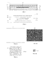
- Figure 1 shows an artificially defective laminate 11 comprising several layers 12a, 12b, ..., 12f of a composite material and an insert 15 for simulating a delamination defect placed between the layers 12c and 12d.
- the location of the insert 15 in the laminate 11 will be defined to suit the defect to be simulated (it can be an internal or a superficial defect).
- the insert 15 can adopt any form although most common forms for simulating real defects are squared and circular patterns, with sizes varying to cope with the severity of the defect to be simulated.
- Figures 2, 3a to 3c, 4a, 4b show the lay-up 13 used for preparing an insert 15 according to one embodiment of the invention comprising:
- the insert 15 avoids the flow of the resin of the layers of composite material 12a, 12b, ..., 12f between the layers of anti-adherent material 21a, 21b during the curing stage of the laminate 11.
- the number and dimensions of the holes 17 is selected to allow a welding of the anti-adherent layers 21a and 21b.
- the size shall be such as not to disturb the laminate 11 in an area comparable to the thickness of each composite layer and with sufficient distance between welding points to not influence each other.
- the size of the holes 17 can be in the order of 1 mm2 and the size of the adhesive film pieces 27 slightly bigger, in the order of 2 mm2.
- the adhesive film pieces 27 shall be of a compatible material with the composite material of the layers 12a, 12b, ..., 12f of the laminate 11.
- the material of the adhesive film pieces 27 can be an epoxy adhesive.
- the adhesive shall be able to reduce its viscosity with the above-mentioned heat application without curing. This allows the flow of the adhesive and a reduced thickness of the adhesive layer in the cured laminate, which does not affect the laminate layers profile.
- the protective base and the protective cover are withdrawn and the insert 15, illustrated in Figure 4b , is ready to be used in the manufacturing process of the artificially defective laminate 11.
- the insert 15 is placed over the layer 12c of the laminate 11 after having applied heat on it to increase its tacking, ensuring thus that the application of the next layer 12d will not move the insert 15.
- the two layers of an anti-adherent material 21a, 21b with four rectangular holes 17 in their borders and the four rectangular adhesive film pieces 27 having a suitable dimension to cover the holes 17 are placed directly over the layer 12c of the laminate 11 so that the lower overflow of the adhesive film pieces 27 reaches the layer 12c, ensuring the fixation of two layers of anti-adherent material 21a, 21b to each other and to the layer 12c.
- the insert 15 impedes the flow of resin of the layers of a composite material 12a, 12b, ..., 12f between the layers of anti-adherent material 21a, 21b during the curing stage of the laminate 11.
- two layers of an anti-adherent material 21a, 21b (without adhesive film pieces between them) of a different size are placed directly over the layer 12c after having applied heat on it to increase its tacking.
- the invention has the following advantages:
- the artificially defective cured laminate 11 according to the invention can be used as a test specimen for conducting structural tests intended to analyse the influence of the defect caused by the insert 15 in the structural integrity of the laminate 11 as in the prior art.
- non-destructive testing techniques i.e. ultrasonic inspection
Landscapes
- Chemical & Material Sciences (AREA)
- Engineering & Computer Science (AREA)
- Composite Materials (AREA)
- Mechanical Engineering (AREA)
- Laminated Bodies (AREA)
Abstract
Description
- This invention relates to structures of composite materials and more in particular to test specimens for analyzing the influence of the presence of delamination defects in composite laminates.
- Composites are made up from individual laminas bonded together at a certain temperature in a single consolidated laminate. Each layer is composed of a mixture of fibers and resin. The resin flows within and between the laminas before getting to its curing temperature.
- Composite laminates are used extensively in the aeronautical industry as well as in other industries.
- Defects appear in composite laminates during manufacture due to material contamination, manufacturing parameter variability or other causes.
- The separation of layers (also called delamination or debonding) is one of said defects.
- To assess the validity of a composite part with delamination defects it is necessary to carry out structural tests on test specimens (i.e. artificially defective laminates) that include artificially simulated delamination defects.
- The prior art teaches the use of test specimens with a layer of polytetrafluoroethylene (PTFE) (whether a flat layer or a folded layer) within the laminate with the shape and size of the typical delamination defects encountered during manufacturing to allow assessing the effect of such defects in the real part. A folded layer is used where a certain delamination between the layers is sought.
- A drawback of this technique is that one flat layer or a folded layer is prone to deviations during the manufacturing of the test specimen due to the reduced tacking of the non-cured composite material against the non-adherent material and also to the tear produced by the roller in automated manufacturing processes that tends to move or unfold the flat layer or the folded layer.
- The present invention is directed to the solution of said drawback.
- It is an object of the present invention to provide an artificially defective cured laminate suitable for being used as a test specimen to simulate real delamination defects produced naturally in the manufacture of a composite part for further testing and assessment of the influence of such defects in the structural integrity of the part.
- It is another object of the present invention to provide manufacturing methods of said artificially defective cured laminate.
- In one aspect, these and other objects are met by an artificially defective cured laminate comprising a plurality of layers of a composite material and an insert of an anti-adherent material between two of said layers for simulating a delamination defect comprising at least two layers of an anti-adherent material (preferably PTFE) arranged for avoiding that the resin of the layers of a composite material can flow between the layers of the anti-adherent material during the curing stage of the laminate. A double layer (or a multi-layer) of non-adherent material guarantees a total separation between the layers of the composite material, including a certain portion of trapped air, to simulate a delamination naturally produced during the manufacture of a composite part.
- Advantageously, the thickness of the layers of anti-adherent material is lesser than the thickness of the layers of composite material.
- In one embodiment, the insert comprises two layers of an anti-adherent material (preferably of a rectangular or circular shape) of the same size bonded in at least two areas of them (preferably four areas close to their edges).
- In another embodiment, the insert comprises two layers of an anti-adherent material of different size, the smaller being placed under the bigger.
- In another aspect, the above-mentioned objects are met by a manufacturing method of an artificially defective cured laminate of a composite material including an inner insert of an anti-adherent material for simulating a delamination defect comprising steps of: a) laying-up a first group of layers of a composite material; b) applying local heat to the area of the last layer where said insert will be placed to increase its tacking; c) placing an insert comprising at least two layers of an anti-adherent material over the heated zone of the last layer of the first group; d) laying-up a second group of layers of a composite material; e) curing the laminate resulting from step d).
- In one embodiment step c) is performed by placing over the last layer of the first group, one upon another, a first and a second layer of an anti-adherent material, being the first layer smaller than the second layer. Even though there is not a full guarantee of the location of the insert in the desired place in the laminate, the different size of the anti-adherent layers and the pre-heating of the subjacent laminate reduces the risk.
- In another embodiment, the insert, comprising two identical layers of an anti-adherent material, is prepared independently by a process comprising the following steps: c1) placing on a working surface, one upon another, a protective base, a first layer of an anti-adherent material with at least a small hole or puncture (preferably four holes in areas close to the borders), at least an adhesive film piece of enough dimension for covering said hole, a second layer of an anti-adherent material and a protective cover; c2) applying heat to the lay-up obtained in the previous step to reduce the viscosity of the adhesive allowing it to flow between the two layers of anti-adherent material; c3) withdrawing the protective base and the protective cover.
- This manufacturing process guarantees the union of the two layers of anti-adherent material through the adhesive seal formed between the two layers as a rivet-like joint by means of the adhesive that flows between the holes. The two layers keep together as a single insert and the heating of the subjacent material in step b) facilitates the fixation of the insert to the desired zone.
- In another embodiment, step c) is performed by placing over the last layer of the first group, one upon another, a first layer of anti-adherent material with at least a hole (preferably four holes in areas close to the borders), at least an adhesive film piece covering said hole, and a second layer of anti-adherent material and applying heat over the second layer of an anti-adherent material larger than the first layer to reduce the viscosity of the adhesive as in the previous embodiment. This manufacturing process guarantees the union of the two layers of the insert and the location of the insert in the desired position in the laminate.
- Other characteristics and advantages of the present invention will be clear from the following detailed description of embodiments illustrative of its object in relation to the attached figures.
-
-
Figures 1 is a schematic cross sectional view of an artificially defective cured laminate according to the present invention. -
Figure 2 is a schematic cross section view of the components used for preparing the insert included in an artificially defective cured laminate according to an embodiment of the present invention. -
Figures 3a, 3b, 3c, 3d and 3e are schematic plan views of the components used for preparing the insert included in an artificially defective cured laminate according to the present invention. -
Figures 4a and 4b are plan views of the insert included in an artificially defective cured laminate according to the present invention in two stages of its preparation. -
Figures 5a and 5b are schematic cross section views of the insert included in an artificially defective cured laminate according to the present invention illustrating the formation of the adhesive seal between the layers of an anti-adherent material. -
Figure 1 shows an artificiallydefective laminate 11 comprisingseveral layers insert 15 for simulating a delamination defect placed between thelayers insert 15 in thelaminate 11 will be defined to suit the defect to be simulated (it can be an internal or a superficial defect). - The
insert 15 can adopt any form although most common forms for simulating real defects are squared and circular patterns, with sizes varying to cope with the severity of the defect to be simulated. -
Figures 2, 3a to3c, 4a, 4b show the lay-up 13 used for preparing aninsert 15 according to one embodiment of the invention comprising: - A protective base and a protective cover comprising a
paper layer 31 capable of withstanding heat (the carrier paper from the prepreg tapes has shown to be effective) and ananti-adherent layer 29 avoiding that some flowing adhesive can be adhered to thepaper layer 31. - Two rectangular layers of an
anti-adherent material rectangular holes 17 in their borders having a thickness lesser than the thickness of the layers of a composite material12a, 12b, ... 12f. - Four rectangular
adhesive film pieces 27 to cover theholes 17. The dimensions of these pieces will be just enough to cover the holes. - Once the lay-
up 13 is prepared over a working surface as illustrated inFigures 2 and4a (a half lay-up), heat is applied on it so that the adhesive will flow through theholes 17 between the twolayers Figure 5a ) to form a rivet-like adhesive seal (seeFigure 5b ) so that the two layers of ananti-adherent material laminate 11. - The
insert 15 avoids the flow of the resin of the layers ofcomposite material anti-adherent material laminate 11. - The number and dimensions of the
holes 17 is selected to allow a welding of theanti-adherent layers laminate 11 in an area comparable to the thickness of each composite layer and with sufficient distance between welding points to not influence each other. The size of theholes 17 can be in the order of 1 mm2 and the size of theadhesive film pieces 27 slightly bigger, in the order of 2 mm2. - The
adhesive film pieces 27 shall be of a compatible material with the composite material of thelayers laminate 11. For example, for a carbon reinforced thermoplastic material, the material of theadhesive film pieces 27 can be an epoxy adhesive. The adhesive shall be able to reduce its viscosity with the above-mentioned heat application without curing. This allows the flow of the adhesive and a reduced thickness of the adhesive layer in the cured laminate, which does not affect the laminate layers profile. - After the application of heat, the protective base and the protective cover are withdrawn and the
insert 15, illustrated inFigure 4b , is ready to be used in the manufacturing process of the artificiallydefective laminate 11. Theinsert 15 is placed over thelayer 12c of thelaminate 11 after having applied heat on it to increase its tacking, ensuring thus that the application of thenext layer 12d will not move theinsert 15. - In another embodiment of the invention, the two layers of an
anti-adherent material rectangular holes 17 in their borders and the four rectangularadhesive film pieces 27 having a suitable dimension to cover theholes 17 are placed directly over thelayer 12c of thelaminate 11 so that the lower overflow of theadhesive film pieces 27 reaches thelayer 12c, ensuring the fixation of two layers ofanti-adherent material layer 12c. - As in the previous embodiment, the
insert 15 impedes the flow of resin of the layers of acomposite material anti-adherent material laminate 11. - In another embodiment of the invention, two layers of an
anti-adherent material layer 12c after having applied heat on it to increase its tacking. This is the simplest embodiment of the invention. Although this embodiment involves a certain risk that the two layers ofanti-adherent material - Among others, the invention has the following advantages:
- The
insert 15 is not moved when the next layer ofcomposite material 12d is laid up. - The two layers of
anti-adherent material - The artificially defective cured
laminate 11 according to the invention can be used as a test specimen for conducting structural tests intended to analyse the influence of the defect caused by theinsert 15 in the structural integrity of the laminate 11 as in the prior art. In this respect, non-destructive testing techniques (i.e. ultrasonic inspection) to confirm size and location of theinsert 15 before the specimen is tested are well known. - Although the present invention has been described in connection with various embodiments, it will be appreciated from the specification that various combinations of elements, variations or improvements therein may be made, and are within the scope of the invention.
Claims (15)
- An artificially defective cured laminate (11) comprising a plurality of layers of a composite material (12a, 12b, ..., 12f) and an insert (15) of an anti-adherent material between two of said layers for simulating a delamination defect, characterized in that said insert (15) comprises at least two layers of an anti-adherent material (21a, 21b) arranged for avoiding that the resin of the layers of a composite material (12a, 12b, ..., 12f) can flow between them during the curing stage of the laminate.
- An artificially defective cured laminate (11) according to claim 1, wherein the thickness of the layers of the anti-adherent material (21a, 21b) is lesser than the thickness of the layers of the composite material (12a, 12b, ..., 12f).
- An artificially defective cured laminate (11) according to any of claims 1-2, wherein the insert (15) comprises two layers of an anti-adherent material (21a, 21b) of the same size bonded in at least two areas of them.
- An artificially defective cured laminate (11) according to claim 3, wherein the layers of the anti-adherent material (21a, 21b) have a rectangular or circular shape and are bonded in four areas close to their edges.
- An artificially defective cured laminate (11) according to any of claims 1-2, wherein the insert (15) comprises two layers of anti-adherent material (21a, 21b) of different size, being placed the smaller under the bigger.
- An artificially defective cured laminate (11) according to any of claims 1-5, wherein said anti-adherent material is polytetrafluoroethylene (PTFE).
- A manufacturing method of an artificially defective cured laminate (11) of a composite material including an inner insert of an anti-adherent material for simulating a delamination defect, characterized by comprising steps of:a) laying-up a first group of layers of a composite material (12a, 12b, 12c);b) applying local heat on the area of the last layer (12c) where said insert (15) will be placed to increase its tacking;c) placing an insert (15) comprising at least two layers of an anti-adherent material (21a, 21b) over the heated area of the last layer (12c) of the first group;d) laying-up a second group of layers of a composite material (12d, 12e, 12f);e) curing the laminate resulting from step d).
- A manufacturing method according to claim 7, wherein the step c) is performed by placing over the last layer (12c) of the first group, one upon another, a first and a second layer of an anti-adherent material (21a, 21b), being the first layer (21a) smaller than the second layer (21b).
- A manufacturing method according to claim 7, wherein the insert (15) of step c) is prepared by a process comprising the following steps:c1) placing on a working surface, one upon the other, a protective base, a first layer of an anti-adherent material (21a) with at least a hole (17), an adhesive film piece (27) of enough dimension for covering said hole (17), a second layer of an anti-adherent material (21b) identical to the first layer (21a) and a protective cover;c2) applying heat to the lay-up (13) obtained in the previous step to reduce the viscosity of the adhesive allowing that can flow between the two layers of an anti-adherent material (21a, 21b);c3) withdrawing the protective base and the protective cover.
- A manufacturing method according to claim 9, wherein said protective base and said protective cover comprise a paper layer (31) and an anti-adherent layer (29).
- A manufacturing method according to claim 7, wherein step c) is performed by:- placing over the last layer (12c) of the first group, one upon another, a first layer of an anti-adherent material (21a) with at least a hole (17), an adhesive film piece (27) covering said hole (17), and a second layer of an anti-adherent material (21b) larger than the first layer (21a);- applying heat over the second layer of an anti-adherent material (21b) to reduce the viscosity of the adhesive allowing it to flow between the two layers of an anti-adherent material (21a, 21b).
- A manufacturing method according to any of claims 9-11, wherein the layers of an anti-adherent material (21a, 21b) have a rectangular or circular shape and four holes (17) in four areas close to their edges.
- A manufacturing method according to any of claims 7-12, wherein the thickness of the layers of an anti-adherent material (21a, 21b) is lesser than the thickness of the layers of a composite material (12a, 12b, ..., 12f).
- A manufacturing method according to any of claims 7-13, wherein said anti-adherent material is polytetrafluoroethylene (PTFE).
- Use of an artificially defective cured laminate (11) according to any of claims 1-6, as a test specimen for conducting structural tests intended to analyze the influence of the defect caused by said insert (15) in the structural integrity of the laminate.
Priority Applications (2)
| Application Number | Priority Date | Filing Date | Title |
|---|---|---|---|
| EP13382058.9A EP2769834B1 (en) | 2013-02-26 | 2013-02-26 | An artificially defective cured laminate. |
| ES13382058.9T ES2583979T3 (en) | 2013-02-26 | 2013-02-26 | An artificially defective cured laminate |
Applications Claiming Priority (1)
| Application Number | Priority Date | Filing Date | Title |
|---|---|---|---|
| EP13382058.9A EP2769834B1 (en) | 2013-02-26 | 2013-02-26 | An artificially defective cured laminate. |
Publications (2)
| Publication Number | Publication Date |
|---|---|
| EP2769834A1 true EP2769834A1 (en) | 2014-08-27 |
| EP2769834B1 EP2769834B1 (en) | 2016-07-06 |
Family
ID=47900987
Family Applications (1)
| Application Number | Title | Priority Date | Filing Date |
|---|---|---|---|
| EP13382058.9A Not-in-force EP2769834B1 (en) | 2013-02-26 | 2013-02-26 | An artificially defective cured laminate. |
Country Status (2)
| Country | Link |
|---|---|
| EP (1) | EP2769834B1 (en) |
| ES (1) | ES2583979T3 (en) |
Cited By (13)
| Publication number | Priority date | Publication date | Assignee | Title |
|---|---|---|---|---|
| CN107330202A (en) * | 2017-07-05 | 2017-11-07 | 北京航空航天大学 | A kind of composite I types layering bridging rule based on virtual hierarchy expanding test determines method |
| US10488369B2 (en) * | 2017-04-06 | 2019-11-26 | United States Of America As Represented By The Administrator Of Nasa | Method for creating a structure for calibration or verification for non-destructive evaluation inspection |
| CN110554094A (en) * | 2019-07-22 | 2019-12-10 | 中国航空工业集团公司济南特种结构研究所 | Artificial simulation defect and preparation method thereof |
| CN111044426A (en) * | 2018-10-15 | 2020-04-21 | 中国商用飞机有限责任公司 | Manufacturing method of porosity contrast test block and porosity contrast test block |
| CN111208195A (en) * | 2018-11-22 | 2020-05-29 | 中国航发商用航空发动机有限责任公司 | Detection structure and detection method for adhesive bonding quality |
| CN112248482A (en) * | 2020-08-25 | 2021-01-22 | 航天材料及工艺研究所 | Preparation method of internal delamination defect of composite material |
| US20210190710A1 (en) * | 2018-09-10 | 2021-06-24 | Facc Ag | Method for producing a fiber-plastic composite reference body and test method |
| CN113324902A (en) * | 2021-05-13 | 2021-08-31 | 山东非金属材料研究所 | Reference block for composite armor plate debonding defect knocking detection and preparation method thereof |
| CN113702512A (en) * | 2021-09-22 | 2021-11-26 | 广东汇天航空航天科技有限公司 | Reference block for nondestructive testing of functional honeycomb composite material and preparation method thereof |
| CN113733594A (en) * | 2021-08-20 | 2021-12-03 | 昌河飞机工业(集团)有限责任公司 | Method and die for manufacturing pre-impregnated glass roving wrinkle defect test piece |
| CN116141706A (en) * | 2023-04-19 | 2023-05-23 | 中南大学 | A prefabrication method for pore defects in composite materials |
| JP2023529029A (en) * | 2020-06-05 | 2023-07-07 | 中国航発商用航空発動機有限責任公司 | Method for manufacturing a bonded structure test block with defects |
| RU2840922C1 (en) * | 2020-06-05 | 2025-05-30 | Аесс Кемешл Эйркрафт Энджин Ко., Лтд. | Test structural glued block with defects manufacturing method |
Families Citing this family (1)
| Publication number | Priority date | Publication date | Assignee | Title |
|---|---|---|---|---|
| FR3162016A1 (en) * | 2024-05-13 | 2025-11-14 | Safran Aircraft Engines | Method for manufacturing a part of revolution from composite material with the insertion of an inter-ply anti-stick coating |
Citations (3)
| Publication number | Priority date | Publication date | Assignee | Title |
|---|---|---|---|---|
| US5142141A (en) * | 1990-09-19 | 1992-08-25 | The Boeing Company | Crack growth measurement network with primary and shunt optical fibers |
| US20100170746A1 (en) * | 2009-01-06 | 2010-07-08 | Cytec Technology Corp. | Structural composite material with improved acoustic and vibrational damping properties |
| EP2363271A1 (en) * | 2010-03-04 | 2011-09-07 | Rolls-Royce plc | A layered component comprising release material between the layers |
-
2013
- 2013-02-26 EP EP13382058.9A patent/EP2769834B1/en not_active Not-in-force
- 2013-02-26 ES ES13382058.9T patent/ES2583979T3/en active Active
Patent Citations (3)
| Publication number | Priority date | Publication date | Assignee | Title |
|---|---|---|---|---|
| US5142141A (en) * | 1990-09-19 | 1992-08-25 | The Boeing Company | Crack growth measurement network with primary and shunt optical fibers |
| US20100170746A1 (en) * | 2009-01-06 | 2010-07-08 | Cytec Technology Corp. | Structural composite material with improved acoustic and vibrational damping properties |
| EP2363271A1 (en) * | 2010-03-04 | 2011-09-07 | Rolls-Royce plc | A layered component comprising release material between the layers |
Cited By (24)
| Publication number | Priority date | Publication date | Assignee | Title |
|---|---|---|---|---|
| US10488369B2 (en) * | 2017-04-06 | 2019-11-26 | United States Of America As Represented By The Administrator Of Nasa | Method for creating a structure for calibration or verification for non-destructive evaluation inspection |
| CN107330202B (en) * | 2017-07-05 | 2020-06-30 | 北京航空航天大学 | A method for determining type I layered bridging rule for composite materials |
| CN107330202A (en) * | 2017-07-05 | 2017-11-07 | 北京航空航天大学 | A kind of composite I types layering bridging rule based on virtual hierarchy expanding test determines method |
| US20210190710A1 (en) * | 2018-09-10 | 2021-06-24 | Facc Ag | Method for producing a fiber-plastic composite reference body and test method |
| US11971379B2 (en) * | 2018-09-10 | 2024-04-30 | Facc Ag | Method for producing a fiber-plastic composite reference body and test method |
| CN111044426A (en) * | 2018-10-15 | 2020-04-21 | 中国商用飞机有限责任公司 | Manufacturing method of porosity contrast test block and porosity contrast test block |
| CN111044426B (en) * | 2018-10-15 | 2021-05-07 | 中国商用飞机有限责任公司 | A kind of manufacturing method of porosity comparison test block and porosity comparison test block |
| CN111208195A (en) * | 2018-11-22 | 2020-05-29 | 中国航发商用航空发动机有限责任公司 | Detection structure and detection method for adhesive bonding quality |
| CN111208195B (en) * | 2018-11-22 | 2022-07-19 | 中国航发商用航空发动机有限责任公司 | Detection structure and detection method for adhesive bonding quality |
| CN110554094B (en) * | 2019-07-22 | 2021-10-15 | 中国航空工业集团公司济南特种结构研究所 | Artificial simulation defect and preparation method thereof |
| CN110554094A (en) * | 2019-07-22 | 2019-12-10 | 中国航空工业集团公司济南特种结构研究所 | Artificial simulation defect and preparation method thereof |
| RU2840922C1 (en) * | 2020-06-05 | 2025-05-30 | Аесс Кемешл Эйркрафт Энджин Ко., Лтд. | Test structural glued block with defects manufacturing method |
| EP4163630A4 (en) * | 2020-06-05 | 2024-03-20 | Aecc Commercial Aircraft Engine Co., Ltd. | MANUFACTURING METHOD FOR DEFECT TEST BLOCK OF A CONNECTION STRUCTURE |
| JP7590342B2 (en) | 2020-06-05 | 2024-11-26 | 中国航発商用航空発動機有限責任公司 | Method for manufacturing a defective bonded structure test block |
| JP2023529029A (en) * | 2020-06-05 | 2023-07-07 | 中国航発商用航空発動機有限責任公司 | Method for manufacturing a bonded structure test block with defects |
| US11951725B2 (en) | 2020-06-05 | 2024-04-09 | Aecc Commercial Aircraft Engine Co., Ltd. | Method of manufacturing bonding structural test block with defects |
| CN112248482B (en) * | 2020-08-25 | 2022-04-12 | 航天材料及工艺研究所 | A kind of preparation method of internal delamination defect of composite material |
| CN112248482A (en) * | 2020-08-25 | 2021-01-22 | 航天材料及工艺研究所 | Preparation method of internal delamination defect of composite material |
| CN113324902A (en) * | 2021-05-13 | 2021-08-31 | 山东非金属材料研究所 | Reference block for composite armor plate debonding defect knocking detection and preparation method thereof |
| CN113733594A (en) * | 2021-08-20 | 2021-12-03 | 昌河飞机工业(集团)有限责任公司 | Method and die for manufacturing pre-impregnated glass roving wrinkle defect test piece |
| CN113733594B (en) * | 2021-08-20 | 2023-03-28 | 昌河飞机工业(集团)有限责任公司 | Method and die for manufacturing pre-impregnated glass roving wrinkle defect test piece |
| CN113702512A (en) * | 2021-09-22 | 2021-11-26 | 广东汇天航空航天科技有限公司 | Reference block for nondestructive testing of functional honeycomb composite material and preparation method thereof |
| CN116141706B (en) * | 2023-04-19 | 2023-07-14 | 中南大学 | Prefabrication method for pore defects of composite material |
| CN116141706A (en) * | 2023-04-19 | 2023-05-23 | 中南大学 | A prefabrication method for pore defects in composite materials |
Also Published As
| Publication number | Publication date |
|---|---|
| ES2583979T3 (en) | 2016-09-23 |
| EP2769834B1 (en) | 2016-07-06 |
Similar Documents
| Publication | Publication Date | Title |
|---|---|---|
| EP2769834B1 (en) | An artificially defective cured laminate. | |
| CN105482723B (en) | Joint assembly and inspection method thereof | |
| US10488369B2 (en) | Method for creating a structure for calibration or verification for non-destructive evaluation inspection | |
| US20070028661A1 (en) | Composite articles with artificial defects and methods for making them | |
| CN110554094B (en) | Artificial simulation defect and preparation method thereof | |
| Moradi et al. | Experimental and numerical study of the effect of using polyurethane instead of Teflon strip to simulate debonding defect in composite patch repairs aluminum plate under thermography inspection | |
| CN109406629A (en) | A kind of test block of the angle R and production method for composite structure ultrasound detection | |
| CN112033874A (en) | Method for obtaining porosity and interface strength of composite material cementing interface | |
| Shin et al. | Pulsed phase thermography imaging of fatigue-loaded composite adhesively bonded joints | |
| CN106769302A (en) | A kind of method for preparing composite material defect testpieces | |
| Pierce et al. | Injection repair of composites for automotive and aerospace applications | |
| US11971379B2 (en) | Method for producing a fiber-plastic composite reference body and test method | |
| CN209311394U (en) | A kind of angle R test block for composite structure ultrasound detection | |
| US11951725B2 (en) | Method of manufacturing bonding structural test block with defects | |
| Telford et al. | A novel method to produce kiss-bonds in composites components for NDI and characterisation purposes | |
| DE102010018980B4 (en) | Method and device for measuring connection properties of a composite material | |
| Lee | Assessment of adhesive bonded repairs | |
| US7935200B1 (en) | Process development protocol and vacuum bag process for carbon-epoxy prepreg production | |
| Jribi et al. | Damage control measures in composites: BVID damage progression | |
| RU2756583C1 (en) | Method for producing reference samples from fiber-reinforced plastic and method for testing | |
| Biswal et al. | Manufacturing aspects of fabrication of composite reference standard for NDT ultrasonic inspection | |
| Jolibois | Characterization of Bonding Defects in Carbon Fiber-Epoxy Plates via Thermal Wave Imaging | |
| Heilmann et al. | Advances in the bondline control technology for the certification of adhesively bonded composite repairs | |
| Ecault et al. | Extended Non-destructive Testing Technique Demonstration in a Realistic Environment with Technology Assessment | |
| BR112021001797B1 (en) | PROCESS FOR MANUFACTURING A COMPOSITE FIBER AND PLASTIC COMPOSITE COMPARISON BODY AND PROCESS FOR TESTING |
Legal Events
| Date | Code | Title | Description |
|---|---|---|---|
| PUAI | Public reference made under article 153(3) epc to a published international application that has entered the european phase |
Free format text: ORIGINAL CODE: 0009012 |
|
| 17P | Request for examination filed |
Effective date: 20130226 |
|
| AK | Designated contracting states |
Kind code of ref document: A1 Designated state(s): AL AT BE BG CH CY CZ DE DK EE ES FI FR GB GR HR HU IE IS IT LI LT LU LV MC MK MT NL NO PL PT RO RS SE SI SK SM TR |
|
| AX | Request for extension of the european patent |
Extension state: BA ME |
|
| R17P | Request for examination filed (corrected) |
Effective date: 20150224 |
|
| RBV | Designated contracting states (corrected) |
Designated state(s): AL AT BE BG CH CY CZ DE DK EE ES FI FR GB GR HR HU IE IS IT LI LT LU LV MC MK MT NL NO PL PT RO RS SE SI SK SM TR |
|
| GRAP | Despatch of communication of intention to grant a patent |
Free format text: ORIGINAL CODE: EPIDOSNIGR1 |
|
| RIC1 | Information provided on ipc code assigned before grant |
Ipc: B29C 65/00 20060101ALI20160215BHEP Ipc: B32B 37/00 20060101ALI20160215BHEP Ipc: B29C 70/86 20060101AFI20160215BHEP Ipc: G01N 1/00 20060101ALI20160215BHEP |
|
| INTG | Intention to grant announced |
Effective date: 20160324 |
|
| GRAS | Grant fee paid |
Free format text: ORIGINAL CODE: EPIDOSNIGR3 |
|
| GRAA | (expected) grant |
Free format text: ORIGINAL CODE: 0009210 |
|
| AK | Designated contracting states |
Kind code of ref document: B1 Designated state(s): AL AT BE BG CH CY CZ DE DK EE ES FI FR GB GR HR HU IE IS IT LI LT LU LV MC MK MT NL NO PL PT RO RS SE SI SK SM TR |
|
| REG | Reference to a national code |
Ref country code: GB Ref legal event code: FG4D |
|
| REG | Reference to a national code |
Ref country code: AT Ref legal event code: REF Ref document number: 810393 Country of ref document: AT Kind code of ref document: T Effective date: 20160715 Ref country code: CH Ref legal event code: EP |
|
| REG | Reference to a national code |
Ref country code: IE Ref legal event code: FG4D |
|
| REG | Reference to a national code |
Ref country code: DE Ref legal event code: R096 Ref document number: 602013009099 Country of ref document: DE |
|
| REG | Reference to a national code |
Ref country code: ES Ref legal event code: FG2A Ref document number: 2583979 Country of ref document: ES Kind code of ref document: T3 Effective date: 20160923 |
|
| REG | Reference to a national code |
Ref country code: NL Ref legal event code: MP Effective date: 20160706 |
|
| REG | Reference to a national code |
Ref country code: LT Ref legal event code: MG4D |
|
| REG | Reference to a national code |
Ref country code: AT Ref legal event code: MK05 Ref document number: 810393 Country of ref document: AT Kind code of ref document: T Effective date: 20160706 |
|
| PG25 | Lapsed in a contracting state [announced via postgrant information from national office to epo] |
Ref country code: IT Free format text: LAPSE BECAUSE OF FAILURE TO SUBMIT A TRANSLATION OF THE DESCRIPTION OR TO PAY THE FEE WITHIN THE PRESCRIBED TIME-LIMIT Effective date: 20160706 Ref country code: FI Free format text: LAPSE BECAUSE OF FAILURE TO SUBMIT A TRANSLATION OF THE DESCRIPTION OR TO PAY THE FEE WITHIN THE PRESCRIBED TIME-LIMIT Effective date: 20160706 Ref country code: IS Free format text: LAPSE BECAUSE OF FAILURE TO SUBMIT A TRANSLATION OF THE DESCRIPTION OR TO PAY THE FEE WITHIN THE PRESCRIBED TIME-LIMIT Effective date: 20161106 Ref country code: RS Free format text: LAPSE BECAUSE OF FAILURE TO SUBMIT A TRANSLATION OF THE DESCRIPTION OR TO PAY THE FEE WITHIN THE PRESCRIBED TIME-LIMIT Effective date: 20160706 Ref country code: NL Free format text: LAPSE BECAUSE OF FAILURE TO SUBMIT A TRANSLATION OF THE DESCRIPTION OR TO PAY THE FEE WITHIN THE PRESCRIBED TIME-LIMIT Effective date: 20160706 Ref country code: HR Free format text: LAPSE BECAUSE OF FAILURE TO SUBMIT A TRANSLATION OF THE DESCRIPTION OR TO PAY THE FEE WITHIN THE PRESCRIBED TIME-LIMIT Effective date: 20160706 Ref country code: LT Free format text: LAPSE BECAUSE OF FAILURE TO SUBMIT A TRANSLATION OF THE DESCRIPTION OR TO PAY THE FEE WITHIN THE PRESCRIBED TIME-LIMIT Effective date: 20160706 Ref country code: NO Free format text: LAPSE BECAUSE OF FAILURE TO SUBMIT A TRANSLATION OF THE DESCRIPTION OR TO PAY THE FEE WITHIN THE PRESCRIBED TIME-LIMIT Effective date: 20161006 |
|
| REG | Reference to a national code |
Ref country code: FR Ref legal event code: PLFP Year of fee payment: 5 |
|
| PG25 | Lapsed in a contracting state [announced via postgrant information from national office to epo] |
Ref country code: AT Free format text: LAPSE BECAUSE OF FAILURE TO SUBMIT A TRANSLATION OF THE DESCRIPTION OR TO PAY THE FEE WITHIN THE PRESCRIBED TIME-LIMIT Effective date: 20160706 Ref country code: GR Free format text: LAPSE BECAUSE OF FAILURE TO SUBMIT A TRANSLATION OF THE DESCRIPTION OR TO PAY THE FEE WITHIN THE PRESCRIBED TIME-LIMIT Effective date: 20161007 Ref country code: LV Free format text: LAPSE BECAUSE OF FAILURE TO SUBMIT A TRANSLATION OF THE DESCRIPTION OR TO PAY THE FEE WITHIN THE PRESCRIBED TIME-LIMIT Effective date: 20160706 Ref country code: PL Free format text: LAPSE BECAUSE OF FAILURE TO SUBMIT A TRANSLATION OF THE DESCRIPTION OR TO PAY THE FEE WITHIN THE PRESCRIBED TIME-LIMIT Effective date: 20160706 Ref country code: BE Free format text: LAPSE BECAUSE OF FAILURE TO SUBMIT A TRANSLATION OF THE DESCRIPTION OR TO PAY THE FEE WITHIN THE PRESCRIBED TIME-LIMIT Effective date: 20160706 Ref country code: SE Free format text: LAPSE BECAUSE OF FAILURE TO SUBMIT A TRANSLATION OF THE DESCRIPTION OR TO PAY THE FEE WITHIN THE PRESCRIBED TIME-LIMIT Effective date: 20160706 Ref country code: PT Free format text: LAPSE BECAUSE OF FAILURE TO SUBMIT A TRANSLATION OF THE DESCRIPTION OR TO PAY THE FEE WITHIN THE PRESCRIBED TIME-LIMIT Effective date: 20161107 |
|
| REG | Reference to a national code |
Ref country code: DE Ref legal event code: R097 Ref document number: 602013009099 Country of ref document: DE |
|
| PG25 | Lapsed in a contracting state [announced via postgrant information from national office to epo] |
Ref country code: EE Free format text: LAPSE BECAUSE OF FAILURE TO SUBMIT A TRANSLATION OF THE DESCRIPTION OR TO PAY THE FEE WITHIN THE PRESCRIBED TIME-LIMIT Effective date: 20160706 Ref country code: RO Free format text: LAPSE BECAUSE OF FAILURE TO SUBMIT A TRANSLATION OF THE DESCRIPTION OR TO PAY THE FEE WITHIN THE PRESCRIBED TIME-LIMIT Effective date: 20160706 |
|
| PGFP | Annual fee paid to national office [announced via postgrant information from national office to epo] |
Ref country code: FR Payment date: 20170217 Year of fee payment: 5 Ref country code: DE Payment date: 20170217 Year of fee payment: 5 |
|
| PLBE | No opposition filed within time limit |
Free format text: ORIGINAL CODE: 0009261 |
|
| STAA | Information on the status of an ep patent application or granted ep patent |
Free format text: STATUS: NO OPPOSITION FILED WITHIN TIME LIMIT |
|
| PG25 | Lapsed in a contracting state [announced via postgrant information from national office to epo] |
Ref country code: CZ Free format text: LAPSE BECAUSE OF FAILURE TO SUBMIT A TRANSLATION OF THE DESCRIPTION OR TO PAY THE FEE WITHIN THE PRESCRIBED TIME-LIMIT Effective date: 20160706 Ref country code: SK Free format text: LAPSE BECAUSE OF FAILURE TO SUBMIT A TRANSLATION OF THE DESCRIPTION OR TO PAY THE FEE WITHIN THE PRESCRIBED TIME-LIMIT Effective date: 20160706 Ref country code: BG Free format text: LAPSE BECAUSE OF FAILURE TO SUBMIT A TRANSLATION OF THE DESCRIPTION OR TO PAY THE FEE WITHIN THE PRESCRIBED TIME-LIMIT Effective date: 20161006 Ref country code: DK Free format text: LAPSE BECAUSE OF FAILURE TO SUBMIT A TRANSLATION OF THE DESCRIPTION OR TO PAY THE FEE WITHIN THE PRESCRIBED TIME-LIMIT Effective date: 20160706 Ref country code: SM Free format text: LAPSE BECAUSE OF FAILURE TO SUBMIT A TRANSLATION OF THE DESCRIPTION OR TO PAY THE FEE WITHIN THE PRESCRIBED TIME-LIMIT Effective date: 20160706 |
|
| PGFP | Annual fee paid to national office [announced via postgrant information from national office to epo] |
Ref country code: GB Payment date: 20170216 Year of fee payment: 5 |
|
| 26N | No opposition filed |
Effective date: 20170407 |
|
| PGFP | Annual fee paid to national office [announced via postgrant information from national office to epo] |
Ref country code: ES Payment date: 20170213 Year of fee payment: 5 |
|
| PG25 | Lapsed in a contracting state [announced via postgrant information from national office to epo] |
Ref country code: SI Free format text: LAPSE BECAUSE OF FAILURE TO SUBMIT A TRANSLATION OF THE DESCRIPTION OR TO PAY THE FEE WITHIN THE PRESCRIBED TIME-LIMIT Effective date: 20160706 |
|
| PG25 | Lapsed in a contracting state [announced via postgrant information from national office to epo] |
Ref country code: MC Free format text: LAPSE BECAUSE OF FAILURE TO SUBMIT A TRANSLATION OF THE DESCRIPTION OR TO PAY THE FEE WITHIN THE PRESCRIBED TIME-LIMIT Effective date: 20160706 |
|
| REG | Reference to a national code |
Ref country code: CH Ref legal event code: PL |
|
| PG25 | Lapsed in a contracting state [announced via postgrant information from national office to epo] |
Ref country code: LI Free format text: LAPSE BECAUSE OF NON-PAYMENT OF DUE FEES Effective date: 20170228 Ref country code: CH Free format text: LAPSE BECAUSE OF NON-PAYMENT OF DUE FEES Effective date: 20170228 |
|
| REG | Reference to a national code |
Ref country code: IE Ref legal event code: MM4A |
|
| PG25 | Lapsed in a contracting state [announced via postgrant information from national office to epo] |
Ref country code: LU Free format text: LAPSE BECAUSE OF NON-PAYMENT OF DUE FEES Effective date: 20170226 |
|
| PG25 | Lapsed in a contracting state [announced via postgrant information from national office to epo] |
Ref country code: IE Free format text: LAPSE BECAUSE OF NON-PAYMENT OF DUE FEES Effective date: 20170226 |
|
| REG | Reference to a national code |
Ref country code: DE Ref legal event code: R119 Ref document number: 602013009099 Country of ref document: DE |
|
| PG25 | Lapsed in a contracting state [announced via postgrant information from national office to epo] |
Ref country code: MT Free format text: LAPSE BECAUSE OF NON-PAYMENT OF DUE FEES Effective date: 20170226 |
|
| GBPC | Gb: european patent ceased through non-payment of renewal fee |
Effective date: 20180226 |
|
| PG25 | Lapsed in a contracting state [announced via postgrant information from national office to epo] |
Ref country code: AL Free format text: LAPSE BECAUSE OF FAILURE TO SUBMIT A TRANSLATION OF THE DESCRIPTION OR TO PAY THE FEE WITHIN THE PRESCRIBED TIME-LIMIT Effective date: 20160706 |
|
| REG | Reference to a national code |
Ref country code: FR Ref legal event code: ST Effective date: 20181031 |
|
| PG25 | Lapsed in a contracting state [announced via postgrant information from national office to epo] |
Ref country code: DE Free format text: LAPSE BECAUSE OF NON-PAYMENT OF DUE FEES Effective date: 20180901 |
|
| PG25 | Lapsed in a contracting state [announced via postgrant information from national office to epo] |
Ref country code: FR Free format text: LAPSE BECAUSE OF NON-PAYMENT OF DUE FEES Effective date: 20180228 Ref country code: GB Free format text: LAPSE BECAUSE OF NON-PAYMENT OF DUE FEES Effective date: 20180226 |
|
| PG25 | Lapsed in a contracting state [announced via postgrant information from national office to epo] |
Ref country code: HU Free format text: LAPSE BECAUSE OF FAILURE TO SUBMIT A TRANSLATION OF THE DESCRIPTION OR TO PAY THE FEE WITHIN THE PRESCRIBED TIME-LIMIT; INVALID AB INITIO Effective date: 20130226 |
|
| REG | Reference to a national code |
Ref country code: ES Ref legal event code: FD2A Effective date: 20190801 |
|
| PG25 | Lapsed in a contracting state [announced via postgrant information from national office to epo] |
Ref country code: CY Free format text: LAPSE BECAUSE OF NON-PAYMENT OF DUE FEES Effective date: 20160706 Ref country code: ES Free format text: LAPSE BECAUSE OF NON-PAYMENT OF DUE FEES Effective date: 20180227 |
|
| PG25 | Lapsed in a contracting state [announced via postgrant information from national office to epo] |
Ref country code: MK Free format text: LAPSE BECAUSE OF FAILURE TO SUBMIT A TRANSLATION OF THE DESCRIPTION OR TO PAY THE FEE WITHIN THE PRESCRIBED TIME-LIMIT Effective date: 20160706 |
|
| PG25 | Lapsed in a contracting state [announced via postgrant information from national office to epo] |
Ref country code: TR Free format text: LAPSE BECAUSE OF FAILURE TO SUBMIT A TRANSLATION OF THE DESCRIPTION OR TO PAY THE FEE WITHIN THE PRESCRIBED TIME-LIMIT Effective date: 20160706 |