EP2769684A2 - Surgical suture device - Google Patents
Surgical suture device Download PDFInfo
- Publication number
- EP2769684A2 EP2769684A2 EP13199161.4A EP13199161A EP2769684A2 EP 2769684 A2 EP2769684 A2 EP 2769684A2 EP 13199161 A EP13199161 A EP 13199161A EP 2769684 A2 EP2769684 A2 EP 2769684A2
- Authority
- EP
- European Patent Office
- Prior art keywords
- stylet
- shaft
- movement
- handle
- medical instrument
- Prior art date
- Legal status (The legal status is an assumption and is not a legal conclusion. Google has not performed a legal analysis and makes no representation as to the accuracy of the status listed.)
- Granted
Links
Images


Classifications
-
- A—HUMAN NECESSITIES
- A61—MEDICAL OR VETERINARY SCIENCE; HYGIENE
- A61B—DIAGNOSIS; SURGERY; IDENTIFICATION
- A61B17/00—Surgical instruments, devices or methods
- A61B17/04—Surgical instruments, devices or methods for suturing wounds; Holders or packages for needles or suture materials
- A61B17/0483—Hand-held instruments for holding sutures
-
- A—HUMAN NECESSITIES
- A61—MEDICAL OR VETERINARY SCIENCE; HYGIENE
- A61B—DIAGNOSIS; SURGERY; IDENTIFICATION
- A61B17/00—Surgical instruments, devices or methods
- A61B17/04—Surgical instruments, devices or methods for suturing wounds; Holders or packages for needles or suture materials
- A61B17/0469—Suturing instruments for use in minimally invasive surgery, e.g. endoscopic surgery
-
- A—HUMAN NECESSITIES
- A61—MEDICAL OR VETERINARY SCIENCE; HYGIENE
- A61B—DIAGNOSIS; SURGERY; IDENTIFICATION
- A61B17/00—Surgical instruments, devices or methods
- A61B17/04—Surgical instruments, devices or methods for suturing wounds; Holders or packages for needles or suture materials
- A61B17/0485—Devices or means, e.g. loops, for capturing the suture thread and threading it through an opening of a suturing instrument or needle eyelet
-
- A—HUMAN NECESSITIES
- A61—MEDICAL OR VETERINARY SCIENCE; HYGIENE
- A61B—DIAGNOSIS; SURGERY; IDENTIFICATION
- A61B17/00—Surgical instruments, devices or methods
- A61B2017/00367—Details of actuation of instruments, e.g. relations between pushing buttons, or the like, and activation of the tool, working tip, or the like
-
- A—HUMAN NECESSITIES
- A61—MEDICAL OR VETERINARY SCIENCE; HYGIENE
- A61B—DIAGNOSIS; SURGERY; IDENTIFICATION
- A61B17/00—Surgical instruments, devices or methods
- A61B2017/0046—Surgical instruments, devices or methods with a releasable handle; with handle and operating part separable
-
- A—HUMAN NECESSITIES
- A61—MEDICAL OR VETERINARY SCIENCE; HYGIENE
- A61B—DIAGNOSIS; SURGERY; IDENTIFICATION
- A61B17/00—Surgical instruments, devices or methods
- A61B17/04—Surgical instruments, devices or methods for suturing wounds; Holders or packages for needles or suture materials
- A61B17/06—Needles ; Sutures; Needle-suture combinations; Holders or packages for needles or suture materials
- A61B17/06004—Means for attaching suture to needle
- A61B2017/06042—Means for attaching suture to needle located close to needle tip
Definitions
- the present invention relates generally to a medical instrument and more particularly, to a surgical device for manipulating a tissue suture and methods of using the same.
- suture placement is desired or necessary arises in endoscopic, arthroscopic, laparoscopic and other surgical procedures, including but not limited to a hernia repair, in which sutures are introduced in the interior of the body.
- sutures must be positioned in difficult to reach orientations or tissue sites in the body which may possibly result in restrictions on the shape, size and number of the tool(s) used to perform a suture placement procedure and/or lead to an increased complexity and duration of the particular procedure. Therefore, it is desirable to provide a manually operated surgical instrument to access a target tissue location and accurately manipulate and place one or more sutures therein, while minimizing factors such as cost, tissue trauma, user fatigue and/or handling difficulties.
- the instrument includes a handle assembly comprising an elongated housing defining an interior chamber and a longitudinal slot formed in the housing.
- the longitudinal slot has a proximal end and a distal end. At least one lateral slot is also formed in the housing.
- An actuation member is moveable in the longitudinal slot between a proximal position and a distal position and moveable in the at least one lateral slot between a first lateral position and a second lateral position.
- the instrument further preferably comprises a hollow shaft having a distal end portion and a proximal end portion removably coupled to the handle assembly, and a longitudinal axis extending between the proximal and distal end portions of the shaft.
- a stylet extends within the hollow shaft and is longitudinally slideable therein, and preferably, the stylet is not rotationally moveable relative to the shaft axis.
- the stylet has a distal end portion with a grasping member configured for engagement with a suture and a proximal end portion extending at least partially into the handle interior chamber.
- the stylet is moveable between a first position wherein the grasping member is retracted into the distal end portion of the shaft and a second position wherein the grasping member extends distally beyond the distal end portion of the shaft. Movement of the actuation member to the distal position within the longitudinal slot correspondingly moves the stylet to the extended position and movement of the actuation member to the proximal position within the longitudinal slot correspondingly moves the stylet to the retracted position. Preferably, movement between the first and second lateral positions does not impart rotational movement of the stylet relative to the shaft.
- a method for using an apparatus to manipulate and place an object in a bodily tissue is disclosed.
- the object is a tissue suture
- the method preferably utilizes an apparatus having a handle assembly comprising an elongated housing defining an interior chamber and a longitudinal slot formed in the housing.
- the longitudinal slot has a proximal end and a distal end and at least one lateral slot formed in the housing.
- An actuation member is moveable in the longitudinal slot between a proximal position and a distal position and is also moveable in the at least one lateral slot between a first lateral position and a second lateral position.
- a hollow shaft having a distal end portion and a proximal end portion is removably coupled to the handle assembly and has a longitudinal axis extending between the proximal and distal end portions of the shaft.
- a stylet extends within the hollow shaft and is longitudinally slideable therein, and preferably, the stylet is not rotationally moveable relative to the shaft axis.
- the stylet has a distal end portion with a grasping member configured for engagement with a suture and a proximal end portion, wherein the actuation member is configured impart proximal and distal longitudinal movement of the stylet relative to the shaft.
- the stylet has a first position wherein the grasping member is retracted into the distal end portion of the shaft and a second position wherein the grasping member extends distally beyond the distal end portion of the shaft.
- the method of using the exemplary apparatus comprises the steps of penetrating a bodily tissue with the apparatus when the stylet is in the retracted position, moving the actuation member distally within the longitudinal slot to move the stylet to the second distally extended position while rotational movement of the stylet relative to the hollow shaft is prevented, manipulating a suture with the grasping member at the distal end portion of the stylet and withdrawing the apparatus from the bodily tissue.
- FIG. 1 illustrates one example of a medical instrument, such as a surgical device shown generally at 2.
- the device includes a handle 4 having a proximal end portion 6 and a distal end portion 8.
- the handle 4 may be constructed from various materials including thermoplastic and/or polymeric materials such as acrylonitrile butadiene styrene (ABS) polymer.
- a suture assembly 10 is coupled to the distal end portion 8 of the handle 4.
- the suture assembly 10 preferably comprises an outer hollow shaft 12 and an inner actuatable stylet 14 that extends longitudinally within the hollow shaft 12.
- the shaft 12 and the stylet 14 may be formed from a variety of materials, including, but not limited to stainless steel.
- the shaft 12 preferably comprises a hollow cannula that may be straight or curved shown in Figures 1 and 2 , respectively, and having a generally circular cross section, although a variety of sizes, shapes and cross-sectional configurations of the shaft 12 may also be used as necessary or desired, depending on the particular intended use of the instrument, the tissue site being accessed, the target suture placement location and/or the procedure being performed.
- the shaft 12 may be flared, such that it has a larger cross-section or outer diameter at the shaft proximal end 16 where the shaft is mounted on or otherwise secured to the handle 4.
- a portion of the shaft 12 may be captured by a flare fitting 18 to secure the suture assembly 10 at the handle distal end 8.
- the shaft 12 may be mounted or secured to the handle 4 by various other acceptable methods including adhesive, bonding, welding and/or one or more fasteners.
- the shaft 12 may have a length of about 15 cm and an outer cross-sectional diameter of about 2.75 mm.
- the cross-sectional dimensions may vary along the length of the shaft.
- the shaft 12 is removably secured to the handle 4 so that it can be detached and replaced with a shaft having alternate configurations and/or dimensions. While the outer hollow shaft 12 may terminate at or near the point at which it is secured to the handle 4, the inner actuatable stylet 14 may extend farther into the handle interior 20, where it may be mounted or removably secured therein as described in further detail below.
- the stylet 14, having a proximal end portion 22 and a distal end portion 24, is disposed coaxially within the hollow shaft 12.
- the stylet 14 may be a generally solid wire rod or elongated structure that is longitudinally slideable within the shaft 12.
- the distal end 24 of the stylet is preferably configured to allow it to pierce, puncture or be pushed or pulled though one or more membrane, graft and tissue layers or perforations formed therein.
- the stylet 14 preferably terminates in a sharpened tip 26 and includes a recessed "hook" or suture grasping member 28 formed in the stylet 14 located just proximal to the sharpened tip 26. This suture grasping member 28 is preferably configured to snag, grasp and retain a suture 30 therein and facilitate manipulation of the suture 30 during use of the instrument.
- the handle 4 preferably includes a mechanism that can be manually actuated by the user, which facilitates longitudinal movement of the stylet 14 relative to the shaft 12.
- a mechanism includes a thumb-actuated slideable trigger 32, although, other mechanisms may also be used for sliding the stylet within the shaft, such as a knob, lever, rolling wheel or ball, button, slide, switch, and the like.
- the stylet 14 is moveable between a distally extended position as illustrated in Figure 5 and a proximally retracted position as illustrated in Figure 6 .
- mechanisms within the handle interior 20 bias or urge the stylet 14 in the retracted position.
- the suture grasping portion 28 In the extended position, the suture grasping portion 28 extends distally beyond the distal end 17 of the shaft, while in the retracted position, the suture grasping portion 28 is preferably withdrawn inside the distal end 17 of the shaft. Yet, as shown in Figure 6 , even when the stylet 14 is in the retracted position, the sharpened tip 26 of the stylet 14 still preferably protrudes or extends beyond the distal end 17 of the shaft.
- the sharpened tip 26 helps the suture assembly 10 to be passed freely through tissue when the stylet 14 is in the retracted position, while the suture grasping portion 28 is covered by the outer hollow shaft 12 and thus preventing the suture grasping portion 28 from snagging or inadvertently tearing the tissue as the suture assembly 10 is passed therethrough.
- the handle 4 includes a user-actuated mechanism that facilitates movement of the stylet 14 relative to the shaft 12.
- the mechanism includes a thumb-actuated trigger 32 that slides within in a generally longitudinal slot 34 or channel that is formed in the handle 4 as shown in Figures 1, 1A and 2 .
- the trigger 32 is moved in a forward or distal direction, this causes the stylet 14 to also move distally to extend the suture grasping portion 28 at least partially out of the distal end 17 of the shaft as shown in Figures 1, 2 and 5 .
- the stylet 14 is retracted back into the shaft 12.
- the trigger 32 can also preferably be moved laterally or "side-to-side" relative to the handle 4 in one or more lateral slots 36, 38 as shown in Figures 1-2 .
- the lateral slots 36, 38 may be located at the proximal-most and distal-most (or both) ends of the longitudinal slot 34.
- the lateral slots 36, 38 may be generally straight channels formed at approximately 90 degree angles from the proximal and distal ends of the longitudinal slot 34, or alternatively, the lateral slots 36, 38 may be angled, curved or otherwise arranged in different configurations that would also allow for the thumb-actuated trigger 32 to move out of the longitudinal slot 34 and into one of the lateral slots in order to secure or lock the stylet 14 in a particular position relative to the shaft 12.
- the stylet 14 is preferably biased in the retracted position, it may be desirable to lock or at least temporarily secure the stylet 14 in the retracted position. This may be accomplished by moving the trigger 32 laterally within the proximally located lateral slot 36 when the stylet 14 is in the fully retracted position and the trigger 32 in its proximal-most position within the longitudinal slot 34 formed on the handle 4. When the trigger 32 has been moved into the lateral slot 36, the user can relax his grip upon the handle 4 and even release his thumb from the trigger 32 and the stylet 14 will remain locked in the retracted position to prevent unwanted distal movement of the stylet.
- the stylet 14 may also be desirable to lock or temporarily secure the stylet 14 in the distal or extended position, where at least a portion of the distal end 24 of the stylet is exposed and extended beyond the distal end 17 of the shaft as Figure 5 illustrates.
- the suture grasping portion 28 located at the distal end 24 of the stylet is extended out of the shaft 12 when the thumb actuated trigger 32 is moved forward to its distal-most position in the longitudinal slot 34 in the handle. At this position, the trigger 32 may be moved laterally into the distally located lateral slot 38 as shown in Figure 3 to lock the stylet 14 in this extended position.
- the grasping portion 28 remains exposed beyond the shaft distal end 17 and is capable of grasping or snagging a suture 30 without the user having to retain his thumb grip on the trigger 32 and manually keep the trigger pushed forward to keep the stylet 14 extended until the suture 30 has been located and grasped.
- the user's thumb can be freed from having to engage the thumb trigger 32 and maintain a forward (distal) pushing force thereon.
- This may have several advantages including, but not limited to, reducing user fatigue, preventing potential slippage or lost grip on the trigger and unwanted or premature retraction of the stylet during the course of a particular procedure.
- the thumb-actuated trigger 32 is part of or is engageable with, an actuatable unit 40.
- the actuatable unit 40 is, in one example, longitudinally translatable within the handle interior 20 in order to control proximal and distal movement of the stylet 14.
- the thumb actuated trigger 32 is secured to, engaged with and/or integrally formed with, a generally hollow cylindrical member 42 that is located within the handle 20. More specifically, a narrowed neck portion 44 extends from the underside of the thumb trigger 32, through the lateral slots 36, 38 and/or longitudinal slot 34 formed in the handle 4, and engages the cylindrical member 42 within the interior of the handle 20.
- An elongated hollow rod 46 extends through the cylindrical member 42, and the proximal end portion 22 of the stylet extends into the handle interior 20 where the stylet 14 is preferably removably secured to and/or within the hollow rod 46.
- the cylindrical member 42 and the elongated rod 46 (and the proximal end of the stylet 22 secured to the rod) form an actuatable unit 40 that can be moved longitudinally between a proximal and distal position within the handle interior 20 by movement of the thumb trigger 32 located on the outside of the handle 4 to accurately control the position of the stylet 14 relative to the shaft 12.
- distal movement of the thumb trigger 32 facilitates distal movement of the actuatable unit 40 within the handle causing the stylet 14 to move to an extended position
- proximal movement of the thumb trigger 32 facilitates proximal movement of the actuatable unit 40 within the handle causing the stylet 14 to retract within the shaft 12.
- a member is located at or near the proximal and distal ends of the rod and extends radially outwardly from the rod 46, thus providing a "stop" on each end of the rod.
- the members or stops 48, 50 may be integrally formed with the rod 46 or, alternatively, one or more of the stops 48, 50 may be separately molded structures that are secured to the rod such as by bonding, adhesive, one or more fasteners and the like.
- the stops 48, 50 on each end of the rod 46 are preferably configured to engage with one or more protrusions 52, 54 that extend radially inwardly from an interior surface of the handle to prevent the rod 46 from sliding longitudinally beyond the respective protrusions 52, 54.
- the rod 46 when the thumb trigger 32 is pushed forward or distally by the user, the rod 46 also slides distally within the handle until the stop 50 at the distal end of the rod 46 abuts the distally located protrusions 54 within the handle or until the thumb trigger 32 is moved to the distal-most point in the longitudinal slot 34.
- the rod 46 having the proximal end 22 of the stylet 14 mounted thereto, is prevented from moving any further forward in the handle interior 20 and, as such, the distal end 24 of the stylet 14 cannot be advanced any further forward out of the distal end 17 of the shaft.
- the rod 46 slides proximally within the handle interior 20 until the stop 48 at the proximal end of the rod 46 abuts the proximally located protrusions 52 within the handle interior 20 or until the thumb trigger 32 is moved to the proximal-most point in the longitudinal slot 34.
- the rod 46 is thus prevented from sliding any further backwards, thus signaling the user that the stylet 14 is fully retracted within the shaft 12.
- a biasing member such as a spring 56
- the spring 56 is preferably positioned in front of the rod 46 so that the proximal end of the spring 56 abuts the distal stop 50 on the rod 46, while the distal end of the spring 56 abuts a distal end portion of the handle interior 20.
- the distal end of the spring 56 may abut or extend into the flare fitting 18 where the suture assembly 10 is mounted to the distal end 8 of the handle 4.
- the spring 56 preferably biases or urges the elongated rod 46 in a proximal direction within the handle interior 20 in order to force the stylet 14 (which is secured within and carried by the rod 46) in the retracted position.
- the spring 56 when the spring 56 is in a relaxed (e.g. an expanded state) as shown in Figure 4 , the stylet is biased rearwardly in the retracted position (and the thumb trigger 32 urged to slide to the proximal-most position in the longitudinal slot 34) until the user manually pushes the thumb trigger 32 forward (in a distal direction) to extend the stylet 14 out of the shaft 12.
- the spring 56 When the user pushes the thumb trigger 32 distally forward, the spring 56 is compressed as shown in Figure 3 , so that in order to keep the stylet 14 in the distally extended position, the user must manually maintain forward pressure or force upon the trigger 32 or, alternatively, slide the trigger 32 into the distally located lateral slot 38 to lock the stylet 14 in the extended position. If the thumb trigger 32 is not moved into the distally located lateral slot 38 to lock the stylet 14 in the extended position, release of the users thumb would allow for the spring 56 to return to its relaxed (expanded) position under the bias of the spring coil, thus pushing the elongated rod 46 and thumb trigger 32 proximally back towards the user so that the stylet 14 retracts back into the distal end 17 of the shaft.
- the cylindrical member 42 may also be flanked on one or both of its distal and/or proximal ends by additional biasing members or springs 58, 60.
- the additional springs 58, 60 are held in place between the proximal and distal ends of the cylindrical member 42 and the proximal 48 and distal stops 50 of the rod 46, respectively.
- the additional biasing members 58, 60 help hold the cylindrical member 42 in a relatively centrally located position on the elongated rod 46 and also help to control any longitudinal sliding of the cylindrical member 42 relative to the rod 46 when the thumb trigger 32 is actuated by the user.
- the additional biasing members 58, 60 still allow for movement of the cylindrical member 42 relative to the elongated rod 46, but prevent the cylindrical member 42 from sliding loosely and freely in either a forward (distal) or backwards (proximal) direction within the handle interior 20 unless the user intentionally supplies a pushing force upon the thumb trigger 32 to initiate movement of the stylet 14 during a particular procedure.
- stops 48 and/or 50 may have at least one channel or groove formed therein. More particularly, stop 48 may include a channel 49 formed therein, and similarly, stop 50 may include a channel 51 formed therein. Preferably, one or more corresponding surfaces that are formed in the handle interior engage the channels 49, 51 to prevent rotational movement of the actuatable unit 40 and of the stylet 14.
- the handle may include one or more raised surfaces that extend radially inwardly from an interior surface of the handle.
- a raised rail or track 53 slides within or otherwise engages channel 49 near the proximal end 6 of the handle 4.
- a raised rail or track 55 slides within or otherwise engages channel 51 near the distal end 8 of the handle 4.
- the stylet 14 when the thumb-actuated trigger 32 is moved into the lateral slots 36, 38 to lock the stylet 14 in either the distally extended position or the proximally retracted position, the stylet 14 preferably does not rotate within the shaft 12 nor does it rotate relative to the device 2.
- the thumb trigger 32 can be moved both longitudinally as well as laterally within the slots 34, 36 and 38 formed in the handle 4 to control longitudinal movement of the stylet 14 and also to lock the stylet in either an extended or retracted position, but the stylet 14 preferably does not rotate, turn, pivot, spin, swivel or the like within the shaft 12 or relative to the longitudinal axis 62 of the device 2 and/or relative to the shaft 12 despite movement of the thumb trigger 32 in any longitudinal and/or lateral direction.
- the suture grasping portion 28 is formed in the distal end portion 24 of the stylet, and prior to performing a particular procedure, it may be desirable for the user to make note of the particular location of the suture grasping portion 28 relative to the remainder of the device 2, and in particular, relative to the shaft 12 and/or handle 4.
- the user may observe whether the suture grasping portion 28 is formed on a particular side of the stylet 14 (and thus faces either left or right of center when the user holds the handle 4 in a position where the thumb trigger 32 is located directly on top of the handle 4) or whether the suture grasping portion 28 is formed on the top or bottom of the stylet 14 (and thus faces either upwards or downwards when the user holds the handle 4 in a position where the thumb trigger 32 is located directly on top of the handle 4).
- the user can recognize the position of the suture grasping portion 28 relative to the device 2 in any number of ways as the user sees fit, and in one particular example, the user may make note of the position of the suture grasping portion 28 relative to the location of the thumb actuated trigger 32 on the handle 4.
- the suture assembly 10 including the suture grasping portion 28, is introduced into a patient's body and is thus concealed or hidden among the tissues or membranes, the user can still be confident of the location of the suture grasping portion 28 based on the position of the remainder of the device 2 that remains external to and is not concealed by the body or tissues.
- the user may be confident of the location of the suture grasping portion 28 as the user manipulates the stylet 14 within the patient's body by noting the position of the thumb trigger 32 on the handle 4, for example, knowing that despite any longitudinal or lateral movement of the thumb trigger 32, there has not been any rotational movement of the stylet 14, and thus, no rotational change in position of the suture grasping portion 28 formed on the distal end 24 of the stylet.
- Any rotational or pivotal movement of the stylet 14 and suture grasping portion 28 that is desired by the user is preferably only accomplished by corresponding rotation or pivoting of the user's wrist, arm or hand that is being used to manipulate the device 2 during a given procedure.
- the device 2 described herein may be alternately configured such that rotational movement of the stylet 14 (and of the suture grasping portion 28 formed on the distal end thereof) may be achieved by lateral movement of the thumb-actuated trigger 32 (or by other suitable user-actuated mechanisms) if necessary or desired.
- the above-described device 2 may be used for a variety of surgical procedures in accordance with the following exemplary methods.
- One exemplary use may include closure of a hernia repair, but one of skill will understand that the device 2 may have a variety of other uses in different procedures and in connection with different parts of the body.
- Manipulation of a suture 30 relative to a particular tissue, membrane, graft or a combination or multiple layers thereof, may be accomplished with the device 2 in several ways.
- a suture 30 may be pushed or pulled by the device 2 from a first side to a second side of a target tissue by grasping a free end of one or more sutures 30 and pushing the suture assembly 10 through the tissue or a perforation therein and releasing the suture 30 on the opposite (distal) side of the tissue.
- the suture assembly 10 may be first inserted or passed though the tissue or perforation therein, and then, the free end of the suture 30 grasped to allow the suture 30 to be pulled back though the tissue and released on the proximal side.
- the device 2 Prior to using the device 2 for manipulating a suture 30, the device 2 is preferably in a relaxed state with the stylet 14 biased in the retracted position within the shaft 12. In this position, the suture grasping portion 28 formed on the distal end portion 24 of the stylet is retracted within the shaft distal end 17 while the sharpened distal tip 26 remains exposed such that the tip 26 is extended beyond and located just distal to the distal end 17 of the shaft.
- the pointed distal tip 26 facilitates easy insertion through the target tissue or a perforation therein, although, in the event that the tissue perforation is pre-existing, it is not necessary that the sharpened tip 26 of the stylet facilitate insertion through the tissue and the shaft 12 can simply be inserted through the tissue perforation.
- the stylet 14 By pushing the thumb-actuated trigger 32 forward or towards the distal end portion 8 of the handle 4, the stylet 14 is pushed distally, preferably so that at least the suture grasping portion 28 clears the distal end 17 of the shaft as Figure 5 illustrates.
- the user To keep the stylet 14 in the distally extended position, the user must either maintain forward pressure on the thumb trigger 32 or alternatively, move the thumb trigger 32 into the distal lateral slot 38 to lock the stylet 14 in the extended position where the thumb trigger 32 can remain without manipulation or pressure from the user's thumb. With the stylet 14 in the extended position beyond the distal end 17 of the shaft, the suture grasping portion 28 is now exposed and available to grasp one or more sutures 30.
- the suture grasping portion 28 preferably includes a hook, a recessed channel, indentation, lip, overhang, catch, clasp, bevel, aperture, depression or similar structure that may be used to catch or snag and at least temporarily hold or retain a portion of a suture 30 or thread therein.
- the suture grasping portion 28 includes a generally C-shaped hook 64 and further preferably includes a recessed portion 66 that is formed or carved into the distal end 24 of the stylet, such that once a suture 30 has been grasped by the distally located hook portion 64, the suture 30 is encouraged to slide into and remain positioned within the recess 66, even when the stylet 14 is in the extended position.
- the suture grasping portion 28 can be configured in a variety of ways that are also suitable for grasping and retaining a suture 30 therein as would be appreciated by one of skill in the art.
- the user can move the thumb trigger 32 out of the distally located lateral slot 38 and back into the longitudinal slot 34 to unlock the stylet 14 from the extended position, or, if the stylet was not locked in position by the thumb trigger 32 in the distal lateral locking slot 38, the user can simply release his thumb from the trigger 32. Release of the trigger permits the spring 56 to move the elongated rod 46 (and stylet mounted therein) proximally so that the stylet 14 returns to the retracted position. As the stylet 14 is drawn back into the hollow shaft 12, the suture grasping portion 28 with a suture 30 held therein is also retracted back into the shaft 12.
- the suture 30 becomes trapped between the recessed surface 66 of the suture-grasping portion 28 and the interior surfaces of the shaft 12.
- the user may retract the stylet 14 back into the shaft only partially so that at least part of the suture grasping portion 28 is still extended beyond the distal end 17 of the shaft, and, in this position, the suture 30 may be held within the hook 64 but may slide laterally or be repositioned within the recess 66.
- the user may retract the stylet 14 fully so that the entire suture grasping portion 28 having a suture 30 threaded there through is pulled all the way back into the shaft 12 to secure and/or "trap" the suture 30 within the shaft 12, as Figure 6 shows.
- the suture 30 preferably cannot be released from the suture grasping portion 28 and also cannot slide laterally within the recess 66 because the suture 30 is tightly captured and locked between the suture grasping portion 28 and the shaft 12.
- the device 2 In this retracted position, the device 2 is now loaded with a suture 30 and can be pushed forward through the target tissue and the suture released on the far or opposite side of the tissue.
- the suture assembly 10 having passed through the target tissue and securely holding a suture 30, it may be desirable to release the suture 30 from the device 2 on the opposite or distal side of the tissue. This may be accomplished by pushing the thumb trigger 32 distally to move the stylet 14 from the retracted position to the extended position. As the stylet 14 extends out of the distal end 17 of the shaft, the suture 30 can be released from the hook 64 on the opposite side of the tissue.
- the suture 30 can remain there undisturbed, or can be further manipulated, tied, or passed through additional target tissues as so desired by the user.
- the stylet 14 may once again be retracted back into the shaft 12 by proximal movement of the thumb trigger 32 and the suture assembly 10 removed from the tissue.
- the device 2 may be manipulated by the user to grasp and secure a suture within the suture grasping portion 28. Once the suture 30 is secured, the device 2 can be pulled back towards the user in a proximal direction in order to pull the suture 30 through the tissue where it can then be released on the proximal side. As with the prior example, the suture 30 can remain in place in this position undisturbed or it can be further manipulated if necessary or desired by the user. With the suture satisfactorily placed in position the suture assembly 10 may be removed from the tissue.
- the device 2 may be used to repeat one or more steps of the above-described method to place one or more sutures 30 to close the perforated tissues, membranes or grafts.
- the sutures 30 may be small gauge and preferably are large gauge such as "0" gage, and may be permanent, bio-absorbable, synthetic or comprised of biological material.
- the handle 4 be constructed of separately molded components that are secured together. More specifically, the handle 4 may be constructed of similar or identical halves that are removably attachable to each other. As such, the handle portions can be separated, giving access to the handle interior 20. This allows the actuatable unit 40 and biasing members 56, 58 and/or 60 to be selectively removed and replaced as necessary or desired. In one example, this may be advantageous because one or more of the springs/biasing members 56, 58, 60 may be removed and replaced with others having a different size, stiffness, biasing force or the like, while also allowing the distal portion of the device 2 (including the stylet 14 and/or hollow shaft 12) to be replaced with others of different shapes or sizes, to accommodate different surgical procedures. In other words, the outer handle portions/halves can remain the same (thus reducing manufacturing costs, molds and/or materials) while other components of the device 2 can be customizable by the user.
Landscapes
- Health & Medical Sciences (AREA)
- Life Sciences & Earth Sciences (AREA)
- Surgery (AREA)
- Heart & Thoracic Surgery (AREA)
- Engineering & Computer Science (AREA)
- Biomedical Technology (AREA)
- Nuclear Medicine, Radiotherapy & Molecular Imaging (AREA)
- Medical Informatics (AREA)
- Molecular Biology (AREA)
- Animal Behavior & Ethology (AREA)
- General Health & Medical Sciences (AREA)
- Public Health (AREA)
- Veterinary Medicine (AREA)
- Surgical Instruments (AREA)
Abstract
Description
- The present invention relates generally to a medical instrument and more particularly, to a surgical device for manipulating a tissue suture and methods of using the same.
- There are a variety of surgical procedures in which it is desirable to place and manipulate sutures in tissues, membranes or in a graft. One particular situation in which suture placement is desired or necessary arises in endoscopic, arthroscopic, laparoscopic and other surgical procedures, including but not limited to a hernia repair, in which sutures are introduced in the interior of the body. Oftentimes, sutures must be positioned in difficult to reach orientations or tissue sites in the body which may possibly result in restrictions on the shape, size and number of the tool(s) used to perform a suture placement procedure and/or lead to an increased complexity and duration of the particular procedure. Therefore, it is desirable to provide a manually operated surgical instrument to access a target tissue location and accurately manipulate and place one or more sutures therein, while minimizing factors such as cost, tissue trauma, user fatigue and/or handling difficulties.
- A medical instrument for manipulating and placing a suture in body tissue is disclosed. In one example, the instrument includes a handle assembly comprising an elongated housing defining an interior chamber and a longitudinal slot formed in the housing. The longitudinal slot has a proximal end and a distal end. At least one lateral slot is also formed in the housing. An actuation member is moveable in the longitudinal slot between a proximal position and a distal position and moveable in the at least one lateral slot between a first lateral position and a second lateral position. The instrument further preferably comprises a hollow shaft having a distal end portion and a proximal end portion removably coupled to the handle assembly, and a longitudinal axis extending between the proximal and distal end portions of the shaft. A stylet extends within the hollow shaft and is longitudinally slideable therein, and preferably, the stylet is not rotationally moveable relative to the shaft axis. The stylet has a distal end portion with a grasping member configured for engagement with a suture and a proximal end portion extending at least partially into the handle interior chamber. The stylet is moveable between a first position wherein the grasping member is retracted into the distal end portion of the shaft and a second position wherein the grasping member extends distally beyond the distal end portion of the shaft. Movement of the actuation member to the distal position within the longitudinal slot correspondingly moves the stylet to the extended position and movement of the actuation member to the proximal position within the longitudinal slot correspondingly moves the stylet to the retracted position. Preferably, movement between the first and second lateral positions does not impart rotational movement of the stylet relative to the shaft.
- In another example, a method for using an apparatus to manipulate and place an object in a bodily tissue is disclosed. In one example, the object is a tissue suture, and the method preferably utilizes an apparatus having a handle assembly comprising an elongated housing defining an interior chamber and a longitudinal slot formed in the housing. The longitudinal slot has a proximal end and a distal end and at least one lateral slot formed in the housing. An actuation member is moveable in the longitudinal slot between a proximal position and a distal position and is also moveable in the at least one lateral slot between a first lateral position and a second lateral position. A hollow shaft having a distal end portion and a proximal end portion is removably coupled to the handle assembly and has a longitudinal axis extending between the proximal and distal end portions of the shaft. A stylet extends within the hollow shaft and is longitudinally slideable therein, and preferably, the stylet is not rotationally moveable relative to the shaft axis. The stylet has a distal end portion with a grasping member configured for engagement with a suture and a proximal end portion, wherein the actuation member is configured impart proximal and distal longitudinal movement of the stylet relative to the shaft. The stylet has a first position wherein the grasping member is retracted into the distal end portion of the shaft and a second position wherein the grasping member extends distally beyond the distal end portion of the shaft.
- In one example, the method of using the exemplary apparatus comprises the steps of penetrating a bodily tissue with the apparatus when the stylet is in the retracted position, moving the actuation member distally within the longitudinal slot to move the stylet to the second distally extended position while rotational movement of the stylet relative to the hollow shaft is prevented, manipulating a suture with the grasping member at the distal end portion of the stylet and withdrawing the apparatus from the bodily tissue.
-
-
Figure 1 is a side view of one example of a surgical device for manipulating a suture with a stylet in an extended position. -
Figure 1A is a side view of another example of a surgical device for manipulating a suture with a stylet in a retracted position and a suture retained at the distal end. -
Figure 2 is a side view of another example of a surgical device for manipulating a suture with a curved stylet. -
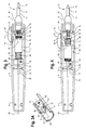
Figure 3 is a side cross-sectional view of one example of the handle portion of a surgical device with the thumb trigger in the distal position. -
Figure 3A is a partial perspective view of the handle portion shown inFigure 3 . -
Figure 4 is a side cross-sectional view of the device ofFigure 3 with the thumb trigger retracted to a proximal position. -
Figure 5 is a perspective view of the distal portion of a surgical device with the stylet extended out of the distal end of the shaft. -
Figure 6 is a partial side cross-sectional view of the surgical device ofFigure 5 with the stylet retracted into the distal end of the shaft and retaining a suture therein. - The examples and embodiments described below are primarily in connection with a medical instrument, such as a surgical device for manipulating an object, including but not limited to a tissue suture and methods of using the same, however, the described device may also be used in connection with a range of medical procedures and methods where necessary or desirable as will be appreciated by one of skill in the art.
Figure 1 illustrates one example of a medical instrument, such as a surgical device shown generally at 2. The device includes ahandle 4 having aproximal end portion 6 and adistal end portion 8. Thehandle 4 may be constructed from various materials including thermoplastic and/or polymeric materials such as acrylonitrile butadiene styrene (ABS) polymer. Asuture assembly 10 is coupled to thedistal end portion 8 of thehandle 4. As shown inFigures 5 and 6 , thesuture assembly 10 preferably comprises an outerhollow shaft 12 and an inneractuatable stylet 14 that extends longitudinally within thehollow shaft 12. Theshaft 12 and thestylet 14 may be formed from a variety of materials, including, but not limited to stainless steel. - In one example, the
shaft 12 preferably comprises a hollow cannula that may be straight or curved shown inFigures 1 and 2 , respectively, and having a generally circular cross section, although a variety of sizes, shapes and cross-sectional configurations of theshaft 12 may also be used as necessary or desired, depending on the particular intended use of the instrument, the tissue site being accessed, the target suture placement location and/or the procedure being performed. For example, theshaft 12 may be flared, such that it has a larger cross-section or outer diameter at the shaftproximal end 16 where the shaft is mounted on or otherwise secured to thehandle 4. As shown in exemplaryFigures 1 ,3 and 4 , a portion of theshaft 12 may be captured by a flare fitting 18 to secure thesuture assembly 10 at the handledistal end 8. Alternatively, theshaft 12 may be mounted or secured to thehandle 4 by various other acceptable methods including adhesive, bonding, welding and/or one or more fasteners. In one non-limiting example, theshaft 12 may have a length of about 15 cm and an outer cross-sectional diameter of about 2.75 mm. Of course, if theshaft 12 is flared, the cross-sectional dimensions may vary along the length of the shaft. It is contemplated that theshaft 12 is removably secured to thehandle 4 so that it can be detached and replaced with a shaft having alternate configurations and/or dimensions. While the outerhollow shaft 12 may terminate at or near the point at which it is secured to thehandle 4, the inneractuatable stylet 14 may extend farther into thehandle interior 20, where it may be mounted or removably secured therein as described in further detail below. - The
stylet 14, having aproximal end portion 22 and adistal end portion 24, is disposed coaxially within thehollow shaft 12. AsFigures 5 and 6 show, thestylet 14 may be a generally solid wire rod or elongated structure that is longitudinally slideable within theshaft 12. In one example, thedistal end 24 of the stylet is preferably configured to allow it to pierce, puncture or be pushed or pulled though one or more membrane, graft and tissue layers or perforations formed therein. For example, thestylet 14 preferably terminates in a sharpenedtip 26 and includes a recessed "hook" orsuture grasping member 28 formed in thestylet 14 located just proximal to the sharpenedtip 26. Thissuture grasping member 28 is preferably configured to snag, grasp and retain asuture 30 therein and facilitate manipulation of thesuture 30 during use of the instrument. - As further illustrated in
Figures 3 and 4 , thehandle 4 preferably includes a mechanism that can be manually actuated by the user, which facilitates longitudinal movement of thestylet 14 relative to theshaft 12. In one example, such a mechanism includes a thumb-actuatedslideable trigger 32, although, other mechanisms may also be used for sliding the stylet within the shaft, such as a knob, lever, rolling wheel or ball, button, slide, switch, and the like. In one example, thestylet 14 is moveable between a distally extended position as illustrated inFigure 5 and a proximally retracted position as illustrated inFigure 6 . Preferably, mechanisms within the handle interior 20 (which are discussed in further detail below) bias or urge thestylet 14 in the retracted position. - In the extended position, the
suture grasping portion 28 extends distally beyond thedistal end 17 of the shaft, while in the retracted position, thesuture grasping portion 28 is preferably withdrawn inside thedistal end 17 of the shaft. Yet, as shown inFigure 6 , even when thestylet 14 is in the retracted position, the sharpenedtip 26 of thestylet 14 still preferably protrudes or extends beyond thedistal end 17 of the shaft. In this way, the sharpenedtip 26 helps thesuture assembly 10 to be passed freely through tissue when thestylet 14 is in the retracted position, while thesuture grasping portion 28 is covered by the outerhollow shaft 12 and thus preventing thesuture grasping portion 28 from snagging or inadvertently tearing the tissue as thesuture assembly 10 is passed therethrough. - Turning back to
Figures 3 and 4 , details of one example of thehandle assembly 4 is illustrated. As previously mentioned, thehandle 4 includes a user-actuated mechanism that facilitates movement of thestylet 14 relative to theshaft 12. Preferably, the mechanism includes a thumb-actuatedtrigger 32 that slides within in a generallylongitudinal slot 34 or channel that is formed in thehandle 4 as shown inFigures 1, 1A and 2 . When thetrigger 32 is moved in a forward or distal direction, this causes thestylet 14 to also move distally to extend thesuture grasping portion 28 at least partially out of thedistal end 17 of the shaft as shown inFigures 1, 2 and5 . When thetrigger 32 is moved back though thelongitudinal slot 34 towards the user in a proximal direction as shown inFigure 1A , thestylet 14 is retracted back into theshaft 12. Thetrigger 32 can also preferably be moved laterally or "side-to-side" relative to thehandle 4 in one or morelateral slots Figures 1-2 . Thelateral slots longitudinal slot 34. Thelateral slots longitudinal slot 34, or alternatively, thelateral slots trigger 32 to move out of thelongitudinal slot 34 and into one of the lateral slots in order to secure or lock thestylet 14 in a particular position relative to theshaft 12. - For example, although the
stylet 14 is preferably biased in the retracted position, it may be desirable to lock or at least temporarily secure thestylet 14 in the retracted position. This may be accomplished by moving thetrigger 32 laterally within the proximally locatedlateral slot 36 when thestylet 14 is in the fully retracted position and thetrigger 32 in its proximal-most position within thelongitudinal slot 34 formed on thehandle 4. When thetrigger 32 has been moved into thelateral slot 36, the user can relax his grip upon thehandle 4 and even release his thumb from thetrigger 32 and thestylet 14 will remain locked in the retracted position to prevent unwanted distal movement of the stylet. This may be desirable, for example, when asuture 30 has been grasped byportion 28 during a particular procedure and the user wants to ensure retention of thesuture 30 inportion 28 during passage of thesuture assembly 10 through tissue and/or when the user wants to release or relax his grip upon thehandle 4 or trigger 32 during use but would like to prevent unintentional longitudinal movement of thestylet 14 within theshaft 12. - Likewise, it may also be desirable to lock or temporarily secure the
stylet 14 in the distal or extended position, where at least a portion of thedistal end 24 of the stylet is exposed and extended beyond thedistal end 17 of the shaft asFigure 5 illustrates. Preferably, thesuture grasping portion 28 located at thedistal end 24 of the stylet is extended out of theshaft 12 when the thumb actuatedtrigger 32 is moved forward to its distal-most position in thelongitudinal slot 34 in the handle. At this position, thetrigger 32 may be moved laterally into the distally locatedlateral slot 38 as shown inFigure 3 to lock thestylet 14 in this extended position. This may be desirable, for example, during a portion of a procedure when thesuture assembly 10 has been inserted through a target tissue location or perforation therein and the user is trying to manipulate thedevice 12 and grasp asuture 30 within graspingportion 28 of the stylet. By locking thestylet 14 in the extended position, the graspingportion 28 remains exposed beyond the shaftdistal end 17 and is capable of grasping or snagging asuture 30 without the user having to retain his thumb grip on thetrigger 32 and manually keep the trigger pushed forward to keep thestylet 14 extended until thesuture 30 has been located and grasped. In other words, the user's thumb can be freed from having to engage thethumb trigger 32 and maintain a forward (distal) pushing force thereon. This may have several advantages including, but not limited to, reducing user fatigue, preventing potential slippage or lost grip on the trigger and unwanted or premature retraction of the stylet during the course of a particular procedure. - It can be seen in
Figures 3 and 4 that the thumb-actuatedtrigger 32 is part of or is engageable with, anactuatable unit 40. Theactuatable unit 40 is, in one example, longitudinally translatable within thehandle interior 20 in order to control proximal and distal movement of thestylet 14. In one example, the thumb actuatedtrigger 32 is secured to, engaged with and/or integrally formed with, a generally hollowcylindrical member 42 that is located within thehandle 20. More specifically, a narrowedneck portion 44 extends from the underside of thethumb trigger 32, through thelateral slots longitudinal slot 34 formed in thehandle 4, and engages thecylindrical member 42 within the interior of thehandle 20. An elongatedhollow rod 46 extends through thecylindrical member 42, and theproximal end portion 22 of the stylet extends into thehandle interior 20 where thestylet 14 is preferably removably secured to and/or within thehollow rod 46. Together, thecylindrical member 42 and the elongated rod 46 (and the proximal end of thestylet 22 secured to the rod) form anactuatable unit 40 that can be moved longitudinally between a proximal and distal position within thehandle interior 20 by movement of thethumb trigger 32 located on the outside of thehandle 4 to accurately control the position of thestylet 14 relative to theshaft 12. In other words, distal movement of thethumb trigger 32 facilitates distal movement of theactuatable unit 40 within the handle causing thestylet 14 to move to an extended position, while proximal movement of thethumb trigger 32 facilitates proximal movement of theactuatable unit 40 within the handle causing thestylet 14 to retract within theshaft 12. - As shown in
Figures 3 and 4 , a member is located at or near the proximal and distal ends of the rod and extends radially outwardly from therod 46, thus providing a "stop" on each end of the rod. The members or stops 48, 50 may be integrally formed with therod 46 or, alternatively, one or more of thestops rod 46 are preferably configured to engage with one ormore protrusions rod 46 from sliding longitudinally beyond therespective protrusions thumb trigger 32 is pushed forward or distally by the user, therod 46 also slides distally within the handle until thestop 50 at the distal end of therod 46 abuts the distally locatedprotrusions 54 within the handle or until thethumb trigger 32 is moved to the distal-most point in thelongitudinal slot 34. Therod 46, having theproximal end 22 of thestylet 14 mounted thereto, is prevented from moving any further forward in thehandle interior 20 and, as such, thedistal end 24 of thestylet 14 cannot be advanced any further forward out of thedistal end 17 of the shaft. Likewise, when thethumb trigger 32 is moved back or proximally towards the user, therod 46 slides proximally within thehandle interior 20 until thestop 48 at the proximal end of therod 46 abuts the proximally locatedprotrusions 52 within thehandle interior 20 or until thethumb trigger 32 is moved to the proximal-most point in thelongitudinal slot 34. Therod 46 is thus prevented from sliding any further backwards, thus signaling the user that thestylet 14 is fully retracted within theshaft 12. - Preferably, a biasing member, such as a
spring 56, coaxially surrounds a portion of theproximal end 22 of the stylet where the stylet extends into thehandle interior 20. Thespring 56 is preferably positioned in front of therod 46 so that the proximal end of thespring 56 abuts thedistal stop 50 on therod 46, while the distal end of thespring 56 abuts a distal end portion of thehandle interior 20. In one example, the distal end of thespring 56 may abut or extend into the flare fitting 18 where thesuture assembly 10 is mounted to thedistal end 8 of thehandle 4. Thespring 56 preferably biases or urges theelongated rod 46 in a proximal direction within thehandle interior 20 in order to force the stylet 14 (which is secured within and carried by the rod 46) in the retracted position. Thus, when thespring 56 is in a relaxed (e.g. an expanded state) as shown inFigure 4 , the stylet is biased rearwardly in the retracted position (and thethumb trigger 32 urged to slide to the proximal-most position in the longitudinal slot 34) until the user manually pushes thethumb trigger 32 forward (in a distal direction) to extend thestylet 14 out of theshaft 12. When the user pushes thethumb trigger 32 distally forward, thespring 56 is compressed as shown inFigure 3 , so that in order to keep thestylet 14 in the distally extended position, the user must manually maintain forward pressure or force upon thetrigger 32 or, alternatively, slide thetrigger 32 into the distally locatedlateral slot 38 to lock thestylet 14 in the extended position. If thethumb trigger 32 is not moved into the distally locatedlateral slot 38 to lock thestylet 14 in the extended position, release of the users thumb would allow for thespring 56 to return to its relaxed (expanded) position under the bias of the spring coil, thus pushing theelongated rod 46 andthumb trigger 32 proximally back towards the user so that thestylet 14 retracts back into thedistal end 17 of the shaft. - As shown in
Figures 3 and 4 , thecylindrical member 42 may also be flanked on one or both of its distal and/or proximal ends by additional biasing members or springs 58, 60. Theadditional springs cylindrical member 42 and the proximal 48 anddistal stops 50 of therod 46, respectively. In one example, theadditional biasing members cylindrical member 42 in a relatively centrally located position on theelongated rod 46 and also help to control any longitudinal sliding of thecylindrical member 42 relative to therod 46 when thethumb trigger 32 is actuated by the user. In other words, theadditional biasing members cylindrical member 42 relative to theelongated rod 46, but prevent thecylindrical member 42 from sliding loosely and freely in either a forward (distal) or backwards (proximal) direction within thehandle interior 20 unless the user intentionally supplies a pushing force upon thethumb trigger 32 to initiate movement of thestylet 14 during a particular procedure. - The design of the
handle 4, and in particular, theactuatable unit 40 that is longitudinally translatable within thehandle interior 20 in order to control proximal and distal movement of thestylet 14, is preferably configured such that rotational movement of thestylet 14 is substantially, if not entirely, prevented. In one example, as shown inFigures 3, 3A and 4 , one or both ofstops 48 and/or 50 may have at least one channel or groove formed therein. More particularly, stop 48 may include achannel 49 formed therein, and similarly, stop 50 may include achannel 51 formed therein. Preferably, one or more corresponding surfaces that are formed in the handle interior engage thechannels actuatable unit 40 and of thestylet 14. - More specifically, the handle may include one or more raised surfaces that extend radially inwardly from an interior surface of the handle. As illustrated in
Figures 3, 3A and 4 , a raised rail or track 53 slides within or otherwise engageschannel 49 near theproximal end 6 of thehandle 4. Likewise, a raised rail or track 55 slides within or otherwise engageschannel 51 near thedistal end 8 of thehandle 4. Thus, when the thumb-actuated trigger is moved in either a forward (distal) direction or a rearward (proximal) direction by the user, thus moving theactuatable unit 40 longitudinally within the handle interior (and correspondingly moving thestylet 14 within the shaft 12), thechannels respective rails stylet 14 carried by the actuatable unit 40) can be achieved by movement of the thumb-trigger 32, yet rotational movement of these structures is prevented. - In one example, when the thumb-actuated
trigger 32 is moved into thelateral slots stylet 14 in either the distally extended position or the proximally retracted position, thestylet 14 preferably does not rotate within theshaft 12 nor does it rotate relative to thedevice 2. In other words, thethumb trigger 32 can be moved both longitudinally as well as laterally within theslots handle 4 to control longitudinal movement of thestylet 14 and also to lock the stylet in either an extended or retracted position, but thestylet 14 preferably does not rotate, turn, pivot, spin, swivel or the like within theshaft 12 or relative to thelongitudinal axis 62 of thedevice 2 and/or relative to theshaft 12 despite movement of thethumb trigger 32 in any longitudinal and/or lateral direction. - As described above and as shown in
Figures 5 and 6 , thesuture grasping portion 28 is formed in thedistal end portion 24 of the stylet, and prior to performing a particular procedure, it may be desirable for the user to make note of the particular location of thesuture grasping portion 28 relative to the remainder of thedevice 2, and in particular, relative to theshaft 12 and/or handle 4. For example, the user may observe whether thesuture grasping portion 28 is formed on a particular side of the stylet 14 (and thus faces either left or right of center when the user holds thehandle 4 in a position where thethumb trigger 32 is located directly on top of the handle 4) or whether thesuture grasping portion 28 is formed on the top or bottom of the stylet 14 (and thus faces either upwards or downwards when the user holds thehandle 4 in a position where thethumb trigger 32 is located directly on top of the handle 4). In any event, the user can recognize the position of thesuture grasping portion 28 relative to thedevice 2 in any number of ways as the user sees fit, and in one particular example, the user may make note of the position of thesuture grasping portion 28 relative to the location of the thumb actuatedtrigger 32 on thehandle 4. - When a particular procedure is initiated and the
suture assembly 10, including thesuture grasping portion 28, is introduced into a patient's body and is thus concealed or hidden among the tissues or membranes, the user can still be confident of the location of thesuture grasping portion 28 based on the position of the remainder of thedevice 2 that remains external to and is not concealed by the body or tissues. Using the example described above, the user may be confident of the location of thesuture grasping portion 28 as the user manipulates thestylet 14 within the patient's body by noting the position of thethumb trigger 32 on thehandle 4, for example, knowing that despite any longitudinal or lateral movement of thethumb trigger 32, there has not been any rotational movement of thestylet 14, and thus, no rotational change in position of thesuture grasping portion 28 formed on thedistal end 24 of the stylet. Any rotational or pivotal movement of thestylet 14 andsuture grasping portion 28 that is desired by the user is preferably only accomplished by corresponding rotation or pivoting of the user's wrist, arm or hand that is being used to manipulate thedevice 2 during a given procedure. - While the preferred examples of the
device 2 are described above, it is also contemplated that thedevice 2 described herein may be alternately configured such that rotational movement of the stylet 14 (and of thesuture grasping portion 28 formed on the distal end thereof) may be achieved by lateral movement of the thumb-actuated trigger 32 (or by other suitable user-actuated mechanisms) if necessary or desired. - The above-described
device 2 may be used for a variety of surgical procedures in accordance with the following exemplary methods. One exemplary use may include closure of a hernia repair, but one of skill will understand that thedevice 2 may have a variety of other uses in different procedures and in connection with different parts of the body. Manipulation of asuture 30 relative to a particular tissue, membrane, graft or a combination or multiple layers thereof, may be accomplished with thedevice 2 in several ways. In one example, asuture 30 may be pushed or pulled by thedevice 2 from a first side to a second side of a target tissue by grasping a free end of one ormore sutures 30 and pushing thesuture assembly 10 through the tissue or a perforation therein and releasing thesuture 30 on the opposite (distal) side of the tissue. Alternatively, thesuture assembly 10 may be first inserted or passed though the tissue or perforation therein, and then, the free end of thesuture 30 grasped to allow thesuture 30 to be pulled back though the tissue and released on the proximal side. - Prior to using the
device 2 for manipulating asuture 30, thedevice 2 is preferably in a relaxed state with thestylet 14 biased in the retracted position within theshaft 12. In this position, thesuture grasping portion 28 formed on thedistal end portion 24 of the stylet is retracted within the shaftdistal end 17 while the sharpeneddistal tip 26 remains exposed such that thetip 26 is extended beyond and located just distal to thedistal end 17 of the shaft. As such, the pointeddistal tip 26 facilitates easy insertion through the target tissue or a perforation therein, although, in the event that the tissue perforation is pre-existing, it is not necessary that the sharpenedtip 26 of the stylet facilitate insertion through the tissue and theshaft 12 can simply be inserted through the tissue perforation. - By pushing the thumb-actuated
trigger 32 forward or towards thedistal end portion 8 of thehandle 4, thestylet 14 is pushed distally, preferably so that at least thesuture grasping portion 28 clears thedistal end 17 of the shaft asFigure 5 illustrates. To keep thestylet 14 in the distally extended position, the user must either maintain forward pressure on thethumb trigger 32 or alternatively, move thethumb trigger 32 into the distallateral slot 38 to lock thestylet 14 in the extended position where thethumb trigger 32 can remain without manipulation or pressure from the user's thumb. With thestylet 14 in the extended position beyond thedistal end 17 of the shaft, thesuture grasping portion 28 is now exposed and available to grasp one or more sutures 30. - For example, the
suture grasping portion 28 preferably includes a hook, a recessed channel, indentation, lip, overhang, catch, clasp, bevel, aperture, depression or similar structure that may be used to catch or snag and at least temporarily hold or retain a portion of asuture 30 or thread therein. AsFigure 5 illustrates, thesuture grasping portion 28 includes a generally C-shapedhook 64 and further preferably includes a recessedportion 66 that is formed or carved into thedistal end 24 of the stylet, such that once asuture 30 has been grasped by the distally locatedhook portion 64, thesuture 30 is encouraged to slide into and remain positioned within therecess 66, even when thestylet 14 is in the extended position. In addition to the above-described configuration, it is also contemplated that thesuture grasping portion 28 can be configured in a variety of ways that are also suitable for grasping and retaining asuture 30 therein as would be appreciated by one of skill in the art. - Once one or
more sutures 30 have been grasped by thehook 64 and are retained therein, the user can move thethumb trigger 32 out of the distally locatedlateral slot 38 and back into thelongitudinal slot 34 to unlock thestylet 14 from the extended position, or, if the stylet was not locked in position by thethumb trigger 32 in the distallateral locking slot 38, the user can simply release his thumb from thetrigger 32. Release of the trigger permits thespring 56 to move the elongated rod 46 (and stylet mounted therein) proximally so that thestylet 14 returns to the retracted position. As thestylet 14 is drawn back into thehollow shaft 12, thesuture grasping portion 28 with asuture 30 held therein is also retracted back into theshaft 12. As shown inFigure 6 , thesuture 30 becomes trapped between the recessedsurface 66 of the suture-graspingportion 28 and the interior surfaces of theshaft 12. The user may retract thestylet 14 back into the shaft only partially so that at least part of thesuture grasping portion 28 is still extended beyond thedistal end 17 of the shaft, and, in this position, thesuture 30 may be held within thehook 64 but may slide laterally or be repositioned within therecess 66. Alternatively, the user may retract thestylet 14 fully so that the entiresuture grasping portion 28 having asuture 30 threaded there through is pulled all the way back into theshaft 12 to secure and/or "trap" thesuture 30 within theshaft 12, asFigure 6 shows. In this position, thesuture 30 preferably cannot be released from thesuture grasping portion 28 and also cannot slide laterally within therecess 66 because thesuture 30 is tightly captured and locked between thesuture grasping portion 28 and theshaft 12. - In this retracted position, the
device 2 is now loaded with asuture 30 and can be pushed forward through the target tissue and the suture released on the far or opposite side of the tissue. For example, with thesuture assembly 10 having passed through the target tissue and securely holding asuture 30, it may be desirable to release thesuture 30 from thedevice 2 on the opposite or distal side of the tissue. This may be accomplished by pushing thethumb trigger 32 distally to move thestylet 14 from the retracted position to the extended position. As thestylet 14 extends out of thedistal end 17 of the shaft, thesuture 30 can be released from thehook 64 on the opposite side of the tissue. Once released, thesuture 30 can remain there undisturbed, or can be further manipulated, tied, or passed through additional target tissues as so desired by the user. With the suture released from its grasp and placed in a target tissue location, thestylet 14 may once again be retracted back into theshaft 12 by proximal movement of thethumb trigger 32 and thesuture assembly 10 removed from the tissue. - Alternatively, if the
suture assembly 10 had been passed through the target tissue prior to grasping thesuture 30, thedevice 2 may be manipulated by the user to grasp and secure a suture within thesuture grasping portion 28. Once thesuture 30 is secured, thedevice 2 can be pulled back towards the user in a proximal direction in order to pull thesuture 30 through the tissue where it can then be released on the proximal side. As with the prior example, thesuture 30 can remain in place in this position undisturbed or it can be further manipulated if necessary or desired by the user. With the suture satisfactorily placed in position thesuture assembly 10 may be removed from the tissue. - During a particular procedure, such as a hernia repair, the
device 2 may be used to repeat one or more steps of the above-described method to place one ormore sutures 30 to close the perforated tissues, membranes or grafts. Thesutures 30 may be small gauge and preferably are large gauge such as "0" gage, and may be permanent, bio-absorbable, synthetic or comprised of biological material. - It is also contemplated that the
handle 4 be constructed of separately molded components that are secured together. More specifically, thehandle 4 may be constructed of similar or identical halves that are removably attachable to each other. As such, the handle portions can be separated, giving access to thehandle interior 20. This allows theactuatable unit 40 and biasingmembers members stylet 14 and/or hollow shaft 12) to be replaced with others of different shapes or sizes, to accommodate different surgical procedures. In other words, the outer handle portions/halves can remain the same (thus reducing manufacturing costs, molds and/or materials) while other components of thedevice 2 can be customizable by the user. - Throughout this specification, unless the context requires otherwise, the words "comprise" and "include" and variations such as "comprising" and "including" will be understood to imply the inclusion of an item or group of items, but not the exclusion of any other item or group items.
- While various embodiments of the invention have been described, it will be apparent to those of ordinary skill in the art that many more embodiments and implementations are possible within the scope of the invention. Furthermore, although various indications have been given as to the scope of this invention, the invention is not limited to any one of these but may reside in two or more of these combined together.
Claims (15)
- A medical instrument for manipulating and placing a suture in body tissue comprising:a. a handle assembly comprisingi. an elongated housing defining an interior chamber,ii. a longitudinal slot formed in the housing, the longitudinal slot having a proximal end and a distal end,iii. at least one lateral slot formed in the housing,iv. an actuation member moveable in the longitudinal slot between a proximal position and a distal position and moveable in the at least one lateral slot between a first lateral position and a second lateral position,b. a hollow shaft having a distal end portion and a proximal end portion removably coupled to the handle assembly, and a longitudinal axis extending between the proximal and distal end portions of the shaft;c. a stylet extending within the hollow shaft and longitudinally slideable therein, wherein the stylet is not rotationally moveable relative to the shaft axis, the stylet having a distal end portion with a grasping member configured for engagement with a suture and a proximal end portion extending at least partially into the handle interior chamber, the stylet having a first position wherein the grasping member is retracted into the distal end portion of the shaft and a second position wherein the grasping member extends distally beyond the distal end portion of the shaft;d. wherein movement of the actuation member to the distal position within the longitudinal slot correspondingly moves the stylet to the extended position and movement of the actuation member to the proximal position within the longitudinal slot correspondingly moves the stylet to the retracted position and wherein movement between the first and second lateral positions does not impart rotational movement of the stylet relative to the shaft.
- The medical instrument of claim 1, wherein the actuation member is connected to a first member of the handle assembly and the stylet is connected to a second member of the handle assembly, said first member configured to rotate about the shaft axis on movement of the actuation member between first and second lateral positions and to slide longitudinally of the shaft axis on movement of the actuation member between said proximal and distal lateral positions; said first member being constrained against rotation about the shaft axis and being coupled with the first member to slide longitudinally of the shaft axis in response to movement of the actuation member between said proximal and distal lateral positions, preferably wherein the second member is a rod and the first member is coaxial with and extends circumferentially around the second member, preferably where relative longitudinal movement between the first and second members is limited by stops and preferably where relative longitudinal movement between the first and second members is opposed by biasing means.
- The medical instrument according to any of the preceding claims wherein the grasping member comprises at least one of a hook, catch, clasp, indentation, recess, depression, bevel, aperture and lip.
- The medical instrument according to any of the preceding claims wherein the actuation member comprises at least one of a trigger, knob, lever, rolling wheel, roller ball, button, slide and switch.
- The medical instrument according to any of the preceding claims wherein the actuation member comprises a thumb-actuated slideable lever.
- The medical instrument according to any of the preceding claims wherein the handle assembly comprises a first lateral slot and a second lateral slot formed in the housing.
- The medical instrument according to any of the preceding claims wherein the first lateral slot extends from the proximal end of the longitudinal slot and the second lateral slot extends from the distal end of the longitudinal slot.
- The medical instrument according to any of the preceding claims wherein the handle assembly further comprises at least one biasing member.
- The medical instrument according to any of the preceding claims wherein the biasing member comprises a spring.
- The medical instrument according to any of the preceding claims wherein the stylet is biased in the retracted position by the biasing member.
- The medical instrument according to any of the preceding claims wherein movement of the actuation member into the first lateral slot locks the stylet in the retracted position and movement of the actuation member into the second lateral slot locks the stylet in the extended position.
- The medical instrument according to any of the preceding claims further comprising an actuatable unit disposed within interior chamber, the actuation member configured to engage the actuatable unit to impart proximal and distal longitudinal movement of the unit within the handle housing.
- The medical instrument according to any of the preceding claims wherein the proximal end portion of the stylet extends at least partially into the handle interior chamber and is removably coupled to the actuatable unit.
- The medical instrument according to any of the preceding claims wherein the actuatable unit has at least one channel formed therein and wherein the at least one channel is configured for slideable engagement with at least one protrusion extending radially inwardly from the interior chamber of the housing.
- The medical instrument according to any of the preceding claims wherein the engagement between the at least one channel and the at least one protrusion is configured to prevent rotational movement of the stylet relative to the hollow shaft.
Applications Claiming Priority (2)
| Application Number | Priority Date | Filing Date | Title |
|---|---|---|---|
| US201261746712P | 2012-12-28 | 2012-12-28 | |
| US14/055,183 US9801624B2 (en) | 2012-12-28 | 2013-10-16 | Surgical suture device and methods of using the same |
Publications (3)
| Publication Number | Publication Date |
|---|---|
| EP2769684A2 true EP2769684A2 (en) | 2014-08-27 |
| EP2769684A3 EP2769684A3 (en) | 2014-12-24 |
| EP2769684B1 EP2769684B1 (en) | 2017-11-08 |
Family
ID=51018053
Family Applications (1)
| Application Number | Title | Priority Date | Filing Date |
|---|---|---|---|
| EP13199161.4A Active EP2769684B1 (en) | 2012-12-28 | 2013-12-20 | Surgical suture device |
Country Status (2)
| Country | Link |
|---|---|
| US (1) | US9801624B2 (en) |
| EP (1) | EP2769684B1 (en) |
Cited By (1)
| Publication number | Priority date | Publication date | Assignee | Title |
|---|---|---|---|---|
| CN111466971A (en) * | 2020-04-15 | 2020-07-31 | 四川大学华西医院 | Stitching instrument for thoracoscopic minimally invasive surgery and control system |
Families Citing this family (20)
| Publication number | Priority date | Publication date | Assignee | Title |
|---|---|---|---|---|
| US6984237B2 (en) | 2002-05-22 | 2006-01-10 | Orthopaedic Biosystems Ltd., Inc. | Suture passing surgical instrument |
| US10098631B2 (en) | 2010-09-10 | 2018-10-16 | Pivot Medical, Inc. | Method and apparatus for passing suture through tissue |
| WO2015066620A1 (en) | 2010-09-10 | 2015-05-07 | Pivot Medical, Inc. | Method and apparatus for passing suture through tissue |
| JP2013537068A (en) | 2010-09-10 | 2013-09-30 | ピボット・メディカル,インコーポレーテッド | Method and instrument for passing a suture through tissue |
| US8556916B2 (en) | 2011-02-14 | 2013-10-15 | Smith & Nephew, Inc. | Method and device for suture manipulation |
| WO2015089034A1 (en) * | 2013-12-09 | 2015-06-18 | Teleflex Medical Incorporated | Sliding suture grasper |
| EP3134008A1 (en) | 2014-04-24 | 2017-03-01 | Smith&Nephew, Inc. | Suture passer |
| US10499904B2 (en) * | 2015-02-17 | 2019-12-10 | Smith & Nephew, Inc. | Anchor insertion system and method of use thereof |
| WO2016142944A2 (en) * | 2015-03-09 | 2016-09-15 | T.A.G. Medical Devices - Agriculture Cooperative Ltd. | Suture capturing device for use in arthroscopic procedures |
| WO2016168422A1 (en) * | 2015-04-15 | 2016-10-20 | Smith & Nephew, Inc. | Suture grasper and method of use thereof |
| CN104887290B (en) * | 2015-06-04 | 2017-08-08 | 桐庐优视医疗器械有限公司 | Band protection hernia repair pincers |
| WO2018081374A1 (en) | 2016-10-31 | 2018-05-03 | Smith & Nephew, Inc. | Suture passer and grasper instrument and method |
| AU2017420762B2 (en) | 2017-06-30 | 2021-01-21 | Wright Medical Technology, Inc. | Soft tissue repair instruments and techniques |
| KR102597762B1 (en) | 2017-12-14 | 2023-11-03 | 콘메드 코포레이션 | Suture passing device |
| US20210077091A1 (en) * | 2018-05-29 | 2021-03-18 | Smith & Nephew, Inc. | Suture passer with locking actuator |
| JP7625610B2 (en) | 2020-02-04 | 2025-02-03 | ボストン サイエンティフィック サイムド,インコーポレイテッド | Actuator Mechanism for the End Effector |
| JP7784531B2 (en) * | 2021-09-29 | 2025-12-11 | ボストン サイエンティフィック サイムド,インコーポレイテッド | Medical device for cutting sutures during minimally invasive procedures |
| US11992389B2 (en) * | 2022-02-25 | 2024-05-28 | Burgeoning Technologies, LLC | Earwax removal device |
| TWI886884B (en) * | 2023-06-08 | 2025-06-11 | 艾斯創生醫股份有限公司 | Surgical device |
| CN117462188B (en) * | 2023-12-28 | 2024-03-29 | 杭州德晋医疗科技有限公司 | Interventional medical instrument |
Family Cites Families (77)
| Publication number | Priority date | Publication date | Assignee | Title |
|---|---|---|---|---|
| US919138A (en) | 1909-03-16 | 1909-04-20 | Clarence A Drake | Surgical needle. |
| US1167014A (en) | 1915-06-25 | 1916-01-04 | William R O'brien | Veterinary surgical instrument. |
| US2808055A (en) | 1953-06-25 | 1957-10-01 | Robert W Thayer | Surgical stitching instruments |
| US3868957A (en) | 1973-10-03 | 1975-03-04 | Regents State Of Florida Board | Vascular clamp |
| US4243048A (en) | 1976-09-21 | 1981-01-06 | Jim Zegeer | Biopsy device |
| US4165747A (en) | 1977-01-28 | 1979-08-28 | Division of Plastic Surgery of the Medical School of Northwestern University | Microvascular clamps with suture retaining means |
| US4874375A (en) | 1987-04-13 | 1989-10-17 | Ellison Arthur E | Tissue retractor |
| US5201741A (en) | 1990-07-24 | 1993-04-13 | Andrew Surgical, Inc. | Surgical snare with shape memory effect wire |
| US5085661A (en) | 1990-10-29 | 1992-02-04 | Gerald Moss | Surgical fastener implantation device |
| US5605162A (en) | 1991-10-15 | 1997-02-25 | Advanced Cardiovascular Systems, Inc. | Method for using a variable stiffness guidewire |
| US5439467A (en) | 1991-12-03 | 1995-08-08 | Vesica Medical, Inc. | Suture passer |
| US5433722A (en) | 1992-01-08 | 1995-07-18 | Sharpe Endosurgical Corporation | Ligature carrier for endoscopic use |
| US5312422A (en) | 1992-07-16 | 1994-05-17 | Linvatec Corporation | Endoscopic suturing needle |
| US5387227A (en) | 1992-09-10 | 1995-02-07 | Grice; O. Drew | Method for use of a laparo-suture needle |
| US5281237A (en) | 1992-09-25 | 1994-01-25 | Gimpelson Richard J | Surgical stitching device and method of use |
| US5649939A (en) | 1992-12-08 | 1997-07-22 | Reddick; Eddie J. | Laparoscopic suture introducer |
| FR2701832A1 (en) | 1993-01-05 | 1994-09-02 | Bluet Jean Luc | Control handle in particular for surgical instrument |
| US5458608A (en) * | 1993-06-03 | 1995-10-17 | Surgin Surgical Instrumentation Inc. | Laparoscopic instruments and methods |
| EP0664688B1 (en) | 1993-07-26 | 2002-06-05 | Innovasive Devices, Inc. | Suture grasping device |
| US5405354A (en) | 1993-08-06 | 1995-04-11 | Vance Products Inc. | Suture driver |
| US5507758A (en) | 1993-08-25 | 1996-04-16 | Inlet Medical, Inc. | Insertable suture grasping probe guide, and methodology for using same |
| US5827299A (en) | 1993-08-25 | 1998-10-27 | Inlet Medical, Inc | Insertable suture passing grasping probe and methodology for using same |
| US5899911A (en) | 1993-08-25 | 1999-05-04 | Inlet Medical, Inc. | Method of using needle-point suture passer to retract and reinforce ligaments |
| US5395382A (en) | 1993-10-22 | 1995-03-07 | Ethicon, Inc. | Device for tying intracorporeal knot |
| US5501692A (en) | 1994-01-28 | 1996-03-26 | Riza; Erol D. | Laparoscopic suture snare |
| US5716369A (en) | 1994-03-25 | 1998-02-10 | Riza; Erol D. | Apparatus facilitating suturing in laparoscopic surgery |
| US5562688A (en) | 1994-03-25 | 1996-10-08 | Riza; Erol D. | Apparatus facilitating suturing in laparoscopic surgery |
| WO1995032669A1 (en) | 1994-06-01 | 1995-12-07 | Perclose, Inc. | Apparatus and method for advancing surgical knots |
| US5562685A (en) | 1994-09-16 | 1996-10-08 | General Surgical Innovations, Inc. | Surgical instrument for placing suture or fasteners |
| US5746753A (en) | 1996-05-13 | 1998-05-05 | Boston Scientific Corporation | Needle grasping apparatus |
| US5791699A (en) | 1996-11-04 | 1998-08-11 | High; Kenneth | Knot tyer |
| US5951067A (en) | 1996-11-04 | 1999-09-14 | High; Kenneth | Knot tyer |
| US5758665A (en) | 1996-11-14 | 1998-06-02 | Suval; William D. | Method for treating varicose veins |
| US5788716A (en) | 1997-01-13 | 1998-08-04 | Kobren; Myles S. | Surgical instrument and method for fallopian tube ligation and biopsy |
| DE19704580C2 (en) | 1997-02-07 | 1999-04-01 | Storz Karl Gmbh & Co | Surgical thread cutter |
| US5904692A (en) | 1997-04-14 | 1999-05-18 | Mitek Surgical Products, Inc. | Needle assembly and method for passing suture |
| US5910148A (en) | 1997-08-06 | 1999-06-08 | Mitek Surgical Products, Inc. | Suture retrograder |
| US5817112A (en) | 1997-09-22 | 1998-10-06 | Surgical Inventions & Innovations, Inc | Christoudias fascial closure device |
| US6723107B1 (en) | 1999-04-19 | 2004-04-20 | Orthopaedic Biosystems Ltd. | Method and apparatus for suturing |
| US8529583B1 (en) | 1999-09-03 | 2013-09-10 | Medtronic, Inc. | Surgical clip removal apparatus |
| EP1289429B1 (en) | 2000-06-05 | 2006-03-15 | Boston Scientific Limited | devices for the treatment of urinary incontinence |
| DE10158142B4 (en) | 2001-11-27 | 2004-04-29 | Karl Storz Gmbh & Co. Kg | Seam set for medical purposes |
| US6746457B2 (en) | 2001-12-07 | 2004-06-08 | Abbott Laboratories | Snared suture trimmer |
| US6699263B2 (en) | 2002-04-05 | 2004-03-02 | Cook Incorporated | Sliding suture anchor |
| US6770084B1 (en) | 2002-06-26 | 2004-08-03 | Opus Medical, Inc. | Suture capture device |
| US20050021055A1 (en) | 2002-08-27 | 2005-01-27 | Souhail Toubia | Surgical closure instrument and methods |
| US7491212B2 (en) | 2003-02-19 | 2009-02-17 | Smith & Nephew, Inc. | Transmitting an actuating force along a curved instrument |
| US8066718B2 (en) | 2003-03-18 | 2011-11-29 | Depuy Mitek, Inc. | Expandable needle suture apparatus and associated handle assembly |
| US8585714B2 (en) | 2003-03-18 | 2013-11-19 | Depuy Mitek, Llc | Expandable needle suture apparatus and associated handle assembly with rotational suture manipulation system |
| US20080269784A1 (en) * | 2003-12-24 | 2008-10-30 | Ryan Abbott | Anastomosis device, tools and methods of using |
| WO2005102179A1 (en) | 2004-03-31 | 2005-11-03 | Wilson-Cook Medical, Inc. | Suture cutting device |
| US7704262B2 (en) | 2004-06-18 | 2010-04-27 | Linvatec Corporation | Hollow suture needle with handle |
| US7803167B2 (en) | 2004-09-27 | 2010-09-28 | Nobles Anthony A | Handle for suturing apparatus |
| US7749250B2 (en) | 2006-02-03 | 2010-07-06 | Biomet Sports Medicine, Llc | Soft tissue repair assembly and associated method |
| US8109945B2 (en) | 2005-02-04 | 2012-02-07 | St. Jude Medical Puerto Rico Llc | Percutaneous suture path tracking device with cutting blade |
| US20060264976A1 (en) | 2005-05-23 | 2006-11-23 | Terry Michael A | System and method for improved suture insertion |
| US20060270900A1 (en) | 2005-05-26 | 2006-11-30 | Chin Albert K | Apparatus and methods for performing ablation |
| JP4488981B2 (en) | 2005-08-23 | 2010-06-23 | 日本シャーウッド株式会社 | Extractor and medical suture tool set |
| US20070083235A1 (en) | 2005-10-11 | 2007-04-12 | Jervis James E | Helical retainer, tool for using the helical retainer, and methods |
| US20070118152A1 (en) | 2005-11-21 | 2007-05-24 | Page Thomas C | Surgical suture passer |
| US8906044B2 (en) | 2006-10-20 | 2014-12-09 | St. Jude Medical, Cardiology Division, Inc. | Knot pusher device |
| US8562629B2 (en) | 2006-10-24 | 2013-10-22 | Arthrocare Corporation | Suture device having selective needle actuation and related method |
| US8579921B2 (en) | 2008-06-18 | 2013-11-12 | Covidien Lp | Spring-type suture securing device |
| CN102292032A (en) * | 2008-11-26 | 2011-12-21 | 史密夫和内修有限公司 | Tissue repair device |
| US8109943B2 (en) | 2009-04-10 | 2012-02-07 | Gordian Surgical, LLC | Systems and methods for suture anchor deployment |
| CN101862211B (en) | 2009-04-14 | 2012-07-25 | 上海交通大学医学院附属第九人民医院 | Temporal-mandibular joint disc suturing fixation apparatus |
| US8162962B2 (en) | 2010-02-24 | 2012-04-24 | Miami Instruments Llc | Knot setter |
| WO2011123714A1 (en) | 2010-03-31 | 2011-10-06 | Siesta Medical, Inc. | Suture passer systems and methods for tongue or other tissue suspension and compression |
| FR2962026B1 (en) | 2010-07-02 | 2013-04-26 | Tornier Inc | SYSTEM FOR SUTURE |
| JP2013537068A (en) | 2010-09-10 | 2013-09-30 | ピボット・メディカル,インコーポレーテッド | Method and instrument for passing a suture through tissue |
| AU2011326756B2 (en) | 2010-10-13 | 2015-10-29 | Synthes Gmbh | Method and apparatus for guiding a suture thread |
| US20130035702A1 (en) | 2011-08-04 | 2013-02-07 | Suture Ease, LLC | Dual insufflation and wound closure devices and methods |
| US8979747B2 (en) | 2011-09-23 | 2015-03-17 | Cooper Surgicalk, Inc. | Endoscopic ports and related kits and methods |
| US9078648B2 (en) | 2011-11-07 | 2015-07-14 | C.R. Bard, Inc. | Instruments for delivering transfascial sutures and methods of transfascial suturing |
| EP2797519B1 (en) | 2011-12-27 | 2023-05-31 | CooperSurgical, Inc. | Suture passer guides and related kits |
| WO2013122690A1 (en) | 2012-02-16 | 2013-08-22 | Coopersurgical, Inc. | Suture passers |
| US9066717B2 (en) | 2012-05-18 | 2015-06-30 | Coopersurgical, Inc. | Suture passer guides and related kits and methods |
-
2013
- 2013-10-16 US US14/055,183 patent/US9801624B2/en active Active
- 2013-12-20 EP EP13199161.4A patent/EP2769684B1/en active Active
Non-Patent Citations (1)
| Title |
|---|
| None |
Cited By (2)
| Publication number | Priority date | Publication date | Assignee | Title |
|---|---|---|---|---|
| CN111466971A (en) * | 2020-04-15 | 2020-07-31 | 四川大学华西医院 | Stitching instrument for thoracoscopic minimally invasive surgery and control system |
| CN111466971B (en) * | 2020-04-15 | 2021-06-11 | 四川大学华西医院 | Stitching instrument for thoracoscopic minimally invasive surgery and control system |
Also Published As
| Publication number | Publication date |
|---|---|
| US9801624B2 (en) | 2017-10-31 |
| EP2769684B1 (en) | 2017-11-08 |
| EP2769684A3 (en) | 2014-12-24 |
| US20140188138A1 (en) | 2014-07-03 |
Similar Documents
| Publication | Publication Date | Title |
|---|---|---|
| EP2769684B1 (en) | Surgical suture device | |
| US8852212B2 (en) | Suturing system and assembly | |
| US10945734B2 (en) | Rotation knob assemblies and surgical instruments including the same | |
| US10278691B2 (en) | Suture assembly including a suture clip | |
| US10363027B2 (en) | Suture assembly including a suture attached to a leader | |
| EP2092893B1 (en) | Biopsy site marker applier | |
| EP2677940B1 (en) | Suture system and assembly including a suture cap formed around a tubular sleeve | |
| EP2800521B1 (en) | Apparatus for tissue closure | |
| US8992550B2 (en) | Suture system with capsule eyelet providing multiple suture tissue fixation | |
| US20100324573A1 (en) | Surgical closure instrument and methods | |
| CN103717149A (en) | Advance suture passer | |
| CA2909960A1 (en) | Biceps tenodesis delivery tools | |
| JP5232471B2 (en) | Deployable needle suturing device and associated handle assembly with suture rotation operation system | |
| AU2014228128A1 (en) | Needle driver | |
| US20120197270A1 (en) | Suture system and assembly including a leader plug | |
| US20130079801A1 (en) | Suturing device with suturing capsule removal mechanism | |
| JP4891945B2 (en) | Endoscopic treatment tool | |
| JP6588967B2 (en) | Tongue advancer assembly for tongue handling system | |
| HK1203794B (en) | Apparatus for tissue closure |
Legal Events
| Date | Code | Title | Description |
|---|---|---|---|
| PUAI | Public reference made under article 153(3) epc to a published international application that has entered the european phase |
Free format text: ORIGINAL CODE: 0009012 |
|
| 17P | Request for examination filed |
Effective date: 20131220 |
|
| AK | Designated contracting states |
Kind code of ref document: A2 Designated state(s): AL AT BE BG CH CY CZ DE DK EE ES FI FR GB GR HR HU IE IS IT LI LT LU LV MC MK MT NL NO PL PT RO RS SE SI SK SM TR |
|
| AX | Request for extension of the european patent |
Extension state: BA ME |
|
| PUAL | Search report despatched |
Free format text: ORIGINAL CODE: 0009013 |
|
| AK | Designated contracting states |
Kind code of ref document: A3 Designated state(s): AL AT BE BG CH CY CZ DE DK EE ES FI FR GB GR HR HU IE IS IT LI LT LU LV MC MK MT NL NO PL PT RO RS SE SI SK SM TR |
|
| AX | Request for extension of the european patent |
Extension state: BA ME |
|
| RIC1 | Information provided on ipc code assigned before grant |
Ipc: A61B 17/04 20060101AFI20141119BHEP |
|
| R17P | Request for examination filed (corrected) |
Effective date: 20150602 |
|
| RBV | Designated contracting states (corrected) |
Designated state(s): AL AT BE BG CH CY CZ DE DK EE ES FI FR GB GR HR HU IE IS IT LI LT LU LV MC MK MT NL NO PL PT RO RS SE SI SK SM TR |
|
| GRAP | Despatch of communication of intention to grant a patent |
Free format text: ORIGINAL CODE: EPIDOSNIGR1 |
|
| INTG | Intention to grant announced |
Effective date: 20170425 |
|
| RIN1 | Information on inventor provided before grant (corrected) |
Inventor name: NEOH, WENHONG Inventor name: MEISHEIMER, JEFFRY S. |
|
| GRAS | Grant fee paid |
Free format text: ORIGINAL CODE: EPIDOSNIGR3 |
|
| GRAJ | Information related to disapproval of communication of intention to grant by the applicant or resumption of examination proceedings by the epo deleted |
Free format text: ORIGINAL CODE: EPIDOSDIGR1 |
|
| GRAL | Information related to payment of fee for publishing/printing deleted |
Free format text: ORIGINAL CODE: EPIDOSDIGR3 |
|
| GRAR | Information related to intention to grant a patent recorded |
Free format text: ORIGINAL CODE: EPIDOSNIGR71 |
|
| GRAA | (expected) grant |
Free format text: ORIGINAL CODE: 0009210 |
|
| INTC | Intention to grant announced (deleted) | ||
| INTG | Intention to grant announced |
Effective date: 20170927 |
|
| AK | Designated contracting states |
Kind code of ref document: B1 Designated state(s): AL AT BE BG CH CY CZ DE DK EE ES FI FR GB GR HR HU IE IS IT LI LT LU LV MC MK MT NL NO PL PT RO RS SE SI SK SM TR |
|
| REG | Reference to a national code |
Ref country code: GB Ref legal event code: FG4D |
|
| REG | Reference to a national code |
Ref country code: CH Ref legal event code: EP Ref country code: AT Ref legal event code: REF Ref document number: 943394 Country of ref document: AT Kind code of ref document: T Effective date: 20171115 |
|
| REG | Reference to a national code |
Ref country code: IE Ref legal event code: FG4D |
|
| REG | Reference to a national code |
Ref country code: DE Ref legal event code: R096 Ref document number: 602013029043 Country of ref document: DE |
|
| REG | Reference to a national code |
Ref country code: NL Ref legal event code: MP Effective date: 20171108 |
|
| REG | Reference to a national code |
Ref country code: LT Ref legal event code: MG4D |
|
| REG | Reference to a national code |
Ref country code: AT Ref legal event code: MK05 Ref document number: 943394 Country of ref document: AT Kind code of ref document: T Effective date: 20171108 |
|
| PG25 | Lapsed in a contracting state [announced via postgrant information from national office to epo] |
Ref country code: ES Free format text: LAPSE BECAUSE OF FAILURE TO SUBMIT A TRANSLATION OF THE DESCRIPTION OR TO PAY THE FEE WITHIN THE PRESCRIBED TIME-LIMIT Effective date: 20171108 Ref country code: FI Free format text: LAPSE BECAUSE OF FAILURE TO SUBMIT A TRANSLATION OF THE DESCRIPTION OR TO PAY THE FEE WITHIN THE PRESCRIBED TIME-LIMIT Effective date: 20171108 Ref country code: LT Free format text: LAPSE BECAUSE OF FAILURE TO SUBMIT A TRANSLATION OF THE DESCRIPTION OR TO PAY THE FEE WITHIN THE PRESCRIBED TIME-LIMIT Effective date: 20171108 Ref country code: SE Free format text: LAPSE BECAUSE OF FAILURE TO SUBMIT A TRANSLATION OF THE DESCRIPTION OR TO PAY THE FEE WITHIN THE PRESCRIBED TIME-LIMIT Effective date: 20171108 Ref country code: NO Free format text: LAPSE BECAUSE OF FAILURE TO SUBMIT A TRANSLATION OF THE DESCRIPTION OR TO PAY THE FEE WITHIN THE PRESCRIBED TIME-LIMIT Effective date: 20180208 Ref country code: NL Free format text: LAPSE BECAUSE OF FAILURE TO SUBMIT A TRANSLATION OF THE DESCRIPTION OR TO PAY THE FEE WITHIN THE PRESCRIBED TIME-LIMIT Effective date: 20171108 |
|
| PG25 | Lapsed in a contracting state [announced via postgrant information from national office to epo] |
Ref country code: GR Free format text: LAPSE BECAUSE OF FAILURE TO SUBMIT A TRANSLATION OF THE DESCRIPTION OR TO PAY THE FEE WITHIN THE PRESCRIBED TIME-LIMIT Effective date: 20180209 Ref country code: AT Free format text: LAPSE BECAUSE OF FAILURE TO SUBMIT A TRANSLATION OF THE DESCRIPTION OR TO PAY THE FEE WITHIN THE PRESCRIBED TIME-LIMIT Effective date: 20171108 Ref country code: LV Free format text: LAPSE BECAUSE OF FAILURE TO SUBMIT A TRANSLATION OF THE DESCRIPTION OR TO PAY THE FEE WITHIN THE PRESCRIBED TIME-LIMIT Effective date: 20171108 Ref country code: BG Free format text: LAPSE BECAUSE OF FAILURE TO SUBMIT A TRANSLATION OF THE DESCRIPTION OR TO PAY THE FEE WITHIN THE PRESCRIBED TIME-LIMIT Effective date: 20180208 Ref country code: HR Free format text: LAPSE BECAUSE OF FAILURE TO SUBMIT A TRANSLATION OF THE DESCRIPTION OR TO PAY THE FEE WITHIN THE PRESCRIBED TIME-LIMIT Effective date: 20171108 Ref country code: RS Free format text: LAPSE BECAUSE OF FAILURE TO SUBMIT A TRANSLATION OF THE DESCRIPTION OR TO PAY THE FEE WITHIN THE PRESCRIBED TIME-LIMIT Effective date: 20171108 Ref country code: IS Free format text: LAPSE BECAUSE OF FAILURE TO SUBMIT A TRANSLATION OF THE DESCRIPTION OR TO PAY THE FEE WITHIN THE PRESCRIBED TIME-LIMIT Effective date: 20180308 |
|
| PG25 | Lapsed in a contracting state [announced via postgrant information from national office to epo] |
Ref country code: EE Free format text: LAPSE BECAUSE OF FAILURE TO SUBMIT A TRANSLATION OF THE DESCRIPTION OR TO PAY THE FEE WITHIN THE PRESCRIBED TIME-LIMIT Effective date: 20171108 Ref country code: CY Free format text: LAPSE BECAUSE OF FAILURE TO SUBMIT A TRANSLATION OF THE DESCRIPTION OR TO PAY THE FEE WITHIN THE PRESCRIBED TIME-LIMIT Effective date: 20171108 Ref country code: CZ Free format text: LAPSE BECAUSE OF FAILURE TO SUBMIT A TRANSLATION OF THE DESCRIPTION OR TO PAY THE FEE WITHIN THE PRESCRIBED TIME-LIMIT Effective date: 20171108 Ref country code: DK Free format text: LAPSE BECAUSE OF FAILURE TO SUBMIT A TRANSLATION OF THE DESCRIPTION OR TO PAY THE FEE WITHIN THE PRESCRIBED TIME-LIMIT Effective date: 20171108 Ref country code: SK Free format text: LAPSE BECAUSE OF FAILURE TO SUBMIT A TRANSLATION OF THE DESCRIPTION OR TO PAY THE FEE WITHIN THE PRESCRIBED TIME-LIMIT Effective date: 20171108 |
|
| REG | Reference to a national code |
Ref country code: CH Ref legal event code: PL |
|
| REG | Reference to a national code |
Ref country code: DE Ref legal event code: R097 Ref document number: 602013029043 Country of ref document: DE |
|
| PG25 | Lapsed in a contracting state [announced via postgrant information from national office to epo] |
Ref country code: SM Free format text: LAPSE BECAUSE OF FAILURE TO SUBMIT A TRANSLATION OF THE DESCRIPTION OR TO PAY THE FEE WITHIN THE PRESCRIBED TIME-LIMIT Effective date: 20171108 Ref country code: IT Free format text: LAPSE BECAUSE OF FAILURE TO SUBMIT A TRANSLATION OF THE DESCRIPTION OR TO PAY THE FEE WITHIN THE PRESCRIBED TIME-LIMIT Effective date: 20171108 Ref country code: RO Free format text: LAPSE BECAUSE OF FAILURE TO SUBMIT A TRANSLATION OF THE DESCRIPTION OR TO PAY THE FEE WITHIN THE PRESCRIBED TIME-LIMIT Effective date: 20171108 Ref country code: PL Free format text: LAPSE BECAUSE OF FAILURE TO SUBMIT A TRANSLATION OF THE DESCRIPTION OR TO PAY THE FEE WITHIN THE PRESCRIBED TIME-LIMIT Effective date: 20171108 |
|
| PLBE | No opposition filed within time limit |
Free format text: ORIGINAL CODE: 0009261 |
|
| STAA | Information on the status of an ep patent application or granted ep patent |
Free format text: STATUS: NO OPPOSITION FILED WITHIN TIME LIMIT |
|
| PG25 | Lapsed in a contracting state [announced via postgrant information from national office to epo] |
Ref country code: MT Free format text: LAPSE BECAUSE OF NON-PAYMENT OF DUE FEES Effective date: 20171220 Ref country code: LU Free format text: LAPSE BECAUSE OF NON-PAYMENT OF DUE FEES Effective date: 20171220 |
|
| REG | Reference to a national code |
Ref country code: FR Ref legal event code: ST Effective date: 20180831 |
|
| 26N | No opposition filed |
Effective date: 20180809 |
|
| REG | Reference to a national code |
Ref country code: BE Ref legal event code: MM Effective date: 20171231 |
|
| PG25 | Lapsed in a contracting state [announced via postgrant information from national office to epo] |
Ref country code: FR Free format text: LAPSE BECAUSE OF NON-PAYMENT OF DUE FEES Effective date: 20180108 |
|
| PG25 | Lapsed in a contracting state [announced via postgrant information from national office to epo] |
Ref country code: CH Free format text: LAPSE BECAUSE OF NON-PAYMENT OF DUE FEES Effective date: 20171231 Ref country code: SI Free format text: LAPSE BECAUSE OF FAILURE TO SUBMIT A TRANSLATION OF THE DESCRIPTION OR TO PAY THE FEE WITHIN THE PRESCRIBED TIME-LIMIT Effective date: 20171108 Ref country code: LI Free format text: LAPSE BECAUSE OF NON-PAYMENT OF DUE FEES Effective date: 20171231 Ref country code: BE Free format text: LAPSE BECAUSE OF NON-PAYMENT OF DUE FEES Effective date: 20171231 |
|
| PG25 | Lapsed in a contracting state [announced via postgrant information from national office to epo] |
Ref country code: HU Free format text: LAPSE BECAUSE OF FAILURE TO SUBMIT A TRANSLATION OF THE DESCRIPTION OR TO PAY THE FEE WITHIN THE PRESCRIBED TIME-LIMIT; INVALID AB INITIO Effective date: 20131220 Ref country code: MC Free format text: LAPSE BECAUSE OF FAILURE TO SUBMIT A TRANSLATION OF THE DESCRIPTION OR TO PAY THE FEE WITHIN THE PRESCRIBED TIME-LIMIT Effective date: 20171108 |
|
| PG25 | Lapsed in a contracting state [announced via postgrant information from national office to epo] |
Ref country code: MK Free format text: LAPSE BECAUSE OF FAILURE TO SUBMIT A TRANSLATION OF THE DESCRIPTION OR TO PAY THE FEE WITHIN THE PRESCRIBED TIME-LIMIT Effective date: 20171108 |
|
| PG25 | Lapsed in a contracting state [announced via postgrant information from national office to epo] |
Ref country code: TR Free format text: LAPSE BECAUSE OF FAILURE TO SUBMIT A TRANSLATION OF THE DESCRIPTION OR TO PAY THE FEE WITHIN THE PRESCRIBED TIME-LIMIT Effective date: 20171108 |
|
| PG25 | Lapsed in a contracting state [announced via postgrant information from national office to epo] |
Ref country code: PT Free format text: LAPSE BECAUSE OF FAILURE TO SUBMIT A TRANSLATION OF THE DESCRIPTION OR TO PAY THE FEE WITHIN THE PRESCRIBED TIME-LIMIT Effective date: 20171108 |
|
| PG25 | Lapsed in a contracting state [announced via postgrant information from national office to epo] |
Ref country code: AL Free format text: LAPSE BECAUSE OF FAILURE TO SUBMIT A TRANSLATION OF THE DESCRIPTION OR TO PAY THE FEE WITHIN THE PRESCRIBED TIME-LIMIT Effective date: 20171108 |
|
| P01 | Opt-out of the competence of the unified patent court (upc) registered |
Effective date: 20230602 |
|
| PGFP | Annual fee paid to national office [announced via postgrant information from national office to epo] |
Ref country code: GB Payment date: 20251223 Year of fee payment: 13 |
|
| PGFP | Annual fee paid to national office [announced via postgrant information from national office to epo] |
Ref country code: IE Payment date: 20251218 Year of fee payment: 13 |
|
| PGFP | Annual fee paid to national office [announced via postgrant information from national office to epo] |
Ref country code: DE Payment date: 20251229 Year of fee payment: 13 |