EP2768750B1 - Foldable conveyor support structure with wrap-around capability - Google Patents
Foldable conveyor support structure with wrap-around capability Download PDFInfo
- Publication number
- EP2768750B1 EP2768750B1 EP12778306.6A EP12778306A EP2768750B1 EP 2768750 B1 EP2768750 B1 EP 2768750B1 EP 12778306 A EP12778306 A EP 12778306A EP 2768750 B1 EP2768750 B1 EP 2768750B1
- Authority
- EP
- European Patent Office
- Prior art keywords
- section
- mid
- support structure
- folded
- conveyor
- Prior art date
- Legal status (The legal status is an assumption and is not a legal conclusion. Google has not performed a legal analysis and makes no representation as to the accuracy of the status listed.)
- Active
Links
Images





Classifications
-
- B—PERFORMING OPERATIONS; TRANSPORTING
- B65—CONVEYING; PACKING; STORING; HANDLING THIN OR FILAMENTARY MATERIAL
- B65G—TRANSPORT OR STORAGE DEVICES, e.g. CONVEYORS FOR LOADING OR TIPPING, SHOP CONVEYOR SYSTEMS OR PNEUMATIC TUBE CONVEYORS
- B65G15/00—Conveyors having endless load-conveying surfaces, i.e. belts and like continuous members, to which tractive effort is transmitted by means other than endless driving elements of similar configuration
- B65G15/22—Conveyors having endless load-conveying surfaces, i.e. belts and like continuous members, to which tractive effort is transmitted by means other than endless driving elements of similar configuration comprising a series of co-operating units
- B65G15/26—Conveyors having endless load-conveying surfaces, i.e. belts and like continuous members, to which tractive effort is transmitted by means other than endless driving elements of similar configuration comprising a series of co-operating units extensible, e.g. telescopic
-
- B—PERFORMING OPERATIONS; TRANSPORTING
- B65—CONVEYING; PACKING; STORING; HANDLING THIN OR FILAMENTARY MATERIAL
- B65G—TRANSPORT OR STORAGE DEVICES, e.g. CONVEYORS FOR LOADING OR TIPPING, SHOP CONVEYOR SYSTEMS OR PNEUMATIC TUBE CONVEYORS
- B65G21/00—Supporting or protective framework or housings for endless load-carriers or traction elements of belt or chain conveyors
- B65G21/02—Supporting or protective framework or housings for endless load-carriers or traction elements of belt or chain conveyors consisting essentially of struts, ties, or like structural elements
- B65G21/06—Supporting or protective framework or housings for endless load-carriers or traction elements of belt or chain conveyors consisting essentially of struts, ties, or like structural elements constructed to facilitate rapid assembly or dismantling
-
- B—PERFORMING OPERATIONS; TRANSPORTING
- B07—SEPARATING SOLIDS FROM SOLIDS; SORTING
- B07B—SEPARATING SOLIDS FROM SOLIDS BY SIEVING, SCREENING, SIFTING OR BY USING GAS CURRENTS; SEPARATING BY OTHER DRY METHODS APPLICABLE TO BULK MATERIAL, e.g. LOOSE ARTICLES FIT TO BE HANDLED LIKE BULK MATERIAL
- B07B1/00—Sieving, screening, sifting, or sorting solid materials using networks, gratings, grids, or the like
- B07B1/005—Transportable screening plants
-
- B—PERFORMING OPERATIONS; TRANSPORTING
- B02—CRUSHING, PULVERISING, OR DISINTEGRATING; PREPARATORY TREATMENT OF GRAIN FOR MILLING
- B02C—CRUSHING, PULVERISING, OR DISINTEGRATING IN GENERAL; MILLING GRAIN
- B02C21/00—Disintegrating plant with or without drying of the material
- B02C21/02—Transportable disintegrating plant
-
- B—PERFORMING OPERATIONS; TRANSPORTING
- B07—SEPARATING SOLIDS FROM SOLIDS; SORTING
- B07B—SEPARATING SOLIDS FROM SOLIDS BY SIEVING, SCREENING, SIFTING OR BY USING GAS CURRENTS; SEPARATING BY OTHER DRY METHODS APPLICABLE TO BULK MATERIAL, e.g. LOOSE ARTICLES FIT TO BE HANDLED LIKE BULK MATERIAL
- B07B1/00—Sieving, screening, sifting, or sorting solid materials using networks, gratings, grids, or the like
Definitions
- the present invention relates to aggregate processing apparatus including foldable support structures for conveyors, especially belt conveyors.
- the application relates particularly but not exclusively to foldable conveyors for aggregate processing apparatus.
- Aggregate processing apparatus may include a plurality of conveyors for transporting aggregate material to or from the apparatus.
- the conveyors include one or more side conveyors, which extend laterally from the processing apparatus during use.
- a problem with such conveyors is that transporting or moving the aggregate processing apparatus can be difficult or impossible when they are deployed.
- the aggregate processing apparatus when being carried by a transport vehicle, the aggregate processing apparatus must fit onto or into the vehicle as well as complying with any height and/or width restrictions that may be applicable to public roads.
- side conveyors are often provided with a foldable support structure that allows them to be folded between the deployed state and a more compact transport state.
- United Kingdom patent application GB2283721 discloses material processing machine with a conveyor having a base inside the machine and sections that fold upwards at an end of the machine and over the top of the machine.
- the invention provides an aggregate processing apparatus as claimed in claim 1.
- the conveyor support structure may comprises a base section, a mid-section pivotably coupled to said base section and a head section pivotably coupled to said mid-section, wherein said conveyor support structure is operable between a deployed state in which the respective obverse face of said mid-section and said head section are substantially co-planar or parallel, and a transport state in which said respective obverse faces are non-coplanar and non-parallel.
- the conveyor structure, and the conveyor of which it is part during use can advantageously be folded, or wrapped, around, for example, an adjacent side and end of the aggregate processing apparatus. This gives greater flexibility in determining where to locate the conveyor/conveyor structure while ensuring that it does not unduly add to the dimensions of the apparatus during transport.
- the aggregate processing apparatus may comprise a conveyor support structure comprising at least one foldable section, wherein said conveyor support structure is operable into and out of a transport state in which at least one of said at least one foldable section is folded to extend across a face of said apparatus, wherein said apparatus includes at least one other foldable section foldable into and out of a transport state in which it extends across, and is preferably disposed substantially parallel with, said face to define a gap therebetween, wherein said conveyor support structure is configured such that at least part of said at least one of said at least one foldable section in its transport state is located in said gap.
- said at least one further foldable section comprises at least part of a hopper wall.
- this arrangement facilitates achieving a relatively close fit between the conveyor (and/or conveyor structure) and the apparatus during transport and so helps to reduce the dimensions of the apparatus during transport.
- the conveyor support structure may comprise a boom structure configured to carry at least one roller recessed with respect to the body of the boom structure such that only part of said at least one roller projects beyond the obverse surface of the body.
- this arrangement reduces the depth of the conveyor structure (and therefore of the associated conveyor) and so helps to reduce the dimensions of the apparatus during transport Preferred features are recited in the dependent claims.
- the aggregate processing apparatus 10 is configured for performing, by way of example, aggregate screening and, as such, comprises an aggregate screening plant 12.
- the apparatus 10 may be configured to perform one or more of a plurality of processes, such as feeding, screening, separating, crushing and/or washing, on one or more types of aggregate material, for example rocks, stones, gravel, sand and/or soil, or any other material that is quarried, mined or excavated.
- the apparatus 10 may include one or more material processing plants adapted to perform one or more of the foregoing processes.
- the aggregate processing apparatus 10 is mobile and comprises one or more wheels and/or tracks 11 mounted on a chassis 13.
- the apparatus 10 is usually self-propelled and to this end may comprise a drive system (not shown), e.g. comprising an engine, for driving the wheels/tracks 11.
- the apparatus 10 may include a power plant 9, which may comprise the engine and other components of the drive system and/or other apparatus for powering the apparatus, e.g. hydraulic and/or pneumatic apparatus for powering rams.
- the aggregate processing apparatus 10 includes a front conveyor 14 and a side conveyor 16 for transporting aggregate material to and/or from the apparatus 10.
- a feed hopper 15 is provided above the screening apparatus 12, the screened material being output from the apparatus 10 by one or more of the conveyors 14, 16.
- the conveyors 14, 16 are usually belt-type conveyors, although the belts are not shown in the drawings.
- each of the conveyors 14, 16 is configurable to adopt a transport (folded) state and a use (deployed) state, the respective transport states being depicted in Figure 1 of the drawings and the respective use states being depicted in Figure 2 of the drawings. It will be understood that the invention is not limited to apparatus of the type shown in Figures 1 to 4 , and may for example be used with other configurations of material processing plant(s) and/or conveyor(s).
- the hopper 15 is shaped to define a mouth 17 and comprises at least one wall section 19 arranged to guide aggregate material (not shown) into the mouth 17 when in a use state (as shown in Figures 1 and 3 ).
- a use state as shown in Figures 1 and 3 .
- the wall sections 19 extend at least partially around the mouth 17.
- the wall sections 19 extend upwardly from the mouth 17, and preferably also extend laterally away from the hopper 15.
- the wall sections 19 may be referred to as flares.
- the height of the flares 19 can be problematic when transporting the apparatus 10.
- Each flare 19 is therefore operable to adopt a non-use, or transport, state in which it extends downwardly with respect to the mouth 17. Conveniently, this is achieved by configuring the flares 19 to fold with respect to the hopper 15, typically by means of a pivot mechanism. In the non-use state ( Figures 2 and 4 ) the flares 19 extend alongside a respective side or end of the apparatus 10, and are typically substantially parallel with the respective side or end. Advantageously, the flares 19 are located close, e.g. substantially against, the respective side or end of the apparatus 10 when folded to minimize the overall dimensions of the apparatus 10. Preferably, in respect of at least one flare 19, the arrangement is such that a gap is defined between the flare 19, when folded, and the side/end of the apparatus 10.
- flares 19A, 19B each folds against a respective side of the apparatus 10 such that a gap 21 is defined between the flare and the side.
- flare 19A may be coupled to the apparatus 10 by one or more pivot linkages comprising first and second supports 23, 25 pivotably coupled to one another.
- a suitable gap 21 can be created by selection of the shape and/or size of one or both of the supports 23, 25 and/or the respective location at which they are coupled, respectively, to the flare 19A and apparatus 10.
- Actuation of the flare 19A between the use and non-use states may be effected by any suitable actuator(s), for example a ram assembly 26. Similar pivoting mechanisms may be used to actuate the other flares 19B, 19C.
- the aggregate processing apparatus 10 further includes a conveyor support structure 20 embodying one aspect of the present invention.
- the conveyor support structure 20 forms part of a side conveyor that is located at a side of the apparatus 10 and is deployable to extend outwardly from the apparatus 10, typically in a direction that is substantially perpendicular with the longitudinal axis of the apparatus 10 ( Figures 1 and 3 ), although it may alternatively extend obliquely with respect to the longitudinal axis of the apparatus 10 when deployed.
- the support structure 20 is shown in a folded, or transport, state corresponding to a folded, or transport, state of the side conveyor. In the transport state, the support structure 20 is folded substantially against the apparatus 10.
- Support structure 20 is configured to allow a conveyor belt (not shown) to be fitted thereto, as is described in more detail hereinafter.
- the support structure 20 may alternatively form part of any other suitable conveyor, e.g. an end conveyor.
- the conveyor support structure 20 has an obverse face 31 that faces generally upwardly during use.
- the obverse face 31 corresponds substantially with the obverse face of the conveyor of which the structure 20 forms part.
- the conveyor includes a conveyor belt
- the top flight of the belt runs along the obverse face 31 during use.
- the conveyor may be said to lie substantially in a plane along which material is carried by the conveyor during use, and which is substantially coincident or parallel with the obverse face 31.
- the conveyor support 20 includes a boom structure 22 that is pivotable with respect to a base section 24 between a folded, or transport, state ( Figure 9 ) and a deployed state ( Figure 7 ), which correspond respectively to the transport and deployed states of the conveyor of which the support structure 20, in use, forms part.
- the base section 24 is mountable, preferably removably, on the apparatus 10 or other host apparatus. Alternatively, the base section 24 may be integrally formed with the apparatus 10 or other host apparatus.
- the boom structure 22 comprises a head section 26 and a mid-section 28, the mid-section 28 being located between the head section 26 and the base section 24.
- the head section 26 and mid-section 28 are pivotably coupled to one another, preferably at respective ends 29, 27.
- the coupling which may comprise any suitable conventional coupling or joint, is configured to allow relative pivotable movement between the sections 26, 28 about at least one axis, preferably only one axis.
- the pivot axis traverses (preferably substantially perpendicularly, but otherwise obliquely) the longitudinal axis of the boom structure 22.
- the pivotable coupling may also allow relative pivoting movement about a second axis that is substantially coincident or parallel with the longitudinal axis of the boom structure 22.
- the actuator 34 is coupled between the mid section 28 and the head section 26.
- the actuator 34 typically comprises a powered linear actuator, for example a ram, preferably a double-acting ram, powered in any suitable manner, e.g. hydraulically, electrically or pneumatically.
- the actuator 34 is arranged to move the head section 26 between its folded and deployed states.
- the actuator 34 is operable by a control device (not shown), which may be located on the apparatus 10, or by a wired or wireless remote controller (not shown).
- the actuator 34 is pivotably coupled to the mid-section 28 and to the head section 28.
- the couplings may comprise any suitable conventional coupling or joint.
- the conveyor support structure 20 may be adapted to carry a conveyor in any suitable manner.
- the conveyor comprises a conveyor belt (not shown).
- the head section 26 comprises a roller support 50 at its free end, the roller support carrying a conveyor end drum 52.
- the base section 24 also includes a roller support (not visible) for carrying a conveyor end drum (not visible).
- One or more of the head section 26, mid-section 28 and base section 24 may include one or more roller supports with one or more rollers, e.g. idler rollers.
- the head section 26 and mid-section 28 include roller supports (not visible) for respective idler (or centre) rollers 56, which traverse the body of the head section 26 or mid-section 28 respectively.
- the rollers 56 are rotatable about a respective axis that is substantially perpendicular with the longitudinal axis of the respective section 26, 28, i.e. transverse with respect to the respective section 26, 28. In use, the rollers 56 support the conveyor belt.
- One or more of the head section 26, mid-section 28 and base section 24 may include one or more roller supports (not visible) with one or more troughing rollers 60 and, optionally, a belt retainer 62. When fitted, the conveyor belt extends between the end rollers in an endless loop, the top flight of which is shaped by the troughing rollers 60 when the conveyor is deployed.
- either one or both of the sections 26, 28 comprises a frame or other support member, the frames or other support members being located end-to-end and pivotably coupled to one another in the manner described above.
- the head section 26 and mid-section 28 may each comprise a respective beam, the beams being located end-to-end and pivotably coupled to one another in the manner described above.
- the head section 26 and mid-section 28 are substantially disposed in a common plane in the deployed state.
- the boom structure 22 is substantially linear when deployed. Consequently, the top flight of the conveyor, when deployed, is substantially linear.
- the mid-section 28 is pivotably coupled to the base section 24, preferably at its end 30, opposite end 27.
- the coupling which may comprise any suitable conventional coupling or joint, is configured to allow relative pivotable movement between the mid-section 28 and the base section 24 about at least one axis.
- the coupling is configured to allow the mid-section 28 to pivot between a folded state ( Figures 2 , 5 , 8 and 9 ) in which it is located substantially against the apparatus 10, and a deployed state in which it projects from the apparatus 10, preferably substantially perpendicularly to the longitudinal axis of the apparatus 10.
- the coupling is preferably such that it allows the mid-section to pivot about first and second mutually perpendicular axes.
- the coupling may for example comprise a knuckle joint.
- the actuator 36 is coupled between the base section 24 and the mid section 28.
- the actuator 36 typically comprises a powered linear actuator 36, for example a ram, preferably a double-acting ram, powered in any suitable manner, e.g. hydraulically, electrically or pneumatically.
- the actuator 36 is arranged to move the head section 28 between its folded and deployed states.
- the actuator 36 is operable by a control device (not shown), which may be located on the apparatus 10, or by a wired or wireless remote controller (not shown).
- the actuator 36 is pivotably coupled to the base section 24 and to the mid-section 28, preferably at respective opposite ends 33, 35.
- the coupling with the base section 24 may comprise any suitable conventional coupling or joint.
- the other end 35 of the actuator 36 is coupled to the mid-section 28 by means of any suitable pivotable coupling.
- a support 32 extends between the base section 24 and the mid-section 28 and is pivotable coupled to each to allow the support 32 to move with the mid-section 28 as it pivots between its folded and deployed states.
- End 35 of the actuator 36 is pivotably coupled directly to the support 32 (and thus indirectly coupled to the mid-section 28). This allows the actuator 36 to actuate the mid-section 28 without fouling the conveyor belt.
- the actuators 34 and 36 may be operable independently of one another (by respective or a common control device) or their operation may be linked. In either case, the actuators 34, 36 may be operated simultaneously or in either sequence. Typically, when folding, actuator 36 is operated (fully or partly) before actuator 34 is operated and, when deploying, actuator 34 is operated (fully or partly) before actuator 36 is operated.
- the obverse face 31 of the support structure 20, and therefore of the conveyor, when deployed is substantially planar, but when folded comprises first and second non-coplanar parts corresponding to the head section 26 and mid-section 28 respectively.
- the head section 26 and mid-section 28 are substantially perpendicular to one another when in the folded/transport state and so the corresponding first and second parts of the obverse face are substantially perpendicular.
- the support structure 20 particularly suited to folding around adjacent faces of the apparatus 10 as is described in more detail below.
- the head section 26 and mid-section 28 may be disposed obliquely with respect to one another in the transport state, typically at an obtuse angle.
- the mid-section 28 when the support structure 20 adopts its folded state, the mid-section 28 is located substantially against a side 40 of the apparatus 10, while the head section 26 is located substantially against an end 42 of the apparatus, the end 42 being adjacent and non-parallel with the side 40.
- the side 40 and end 42 are substantially perpendicular with one another.
- the mid-section 28 is foldable such that, when folded, it extends substantially parallel with the longitudinal axis of the apparatus.
- the apparatus 10 may be said to comprise a plurality of faces, including sides, ends, upper, lower, top or bottom faces, the conveyor support structure 20 being configured to fold or wrap around first and second adjacent non-parallel faces.
- one of the faces is a side or end of the apparatus 10, the other being an adjacent end or side respectively.
- one of the faces may be a side or end, the other being an adjacent top or upper surface, or an adjacent underside or lower face.
- the length of the mid-section 28 and head section 26 may be selected to suit the dimensions of the apparatus 10.
- the location of the base section 24 may be chosen accordingly.
- the configuration of the respective pivotable couplings between the base section and the mid-section and between the mid-section and the head section may be selected to suit the relative position of the first and second faces (e.g. side, end, upper or lower etc.) and the relative orientation between the faces (e.g. perpendicular, oblique etc.).
- the boom structure 32 is foldable around first and second adjacent faces that are substantially perpendicular to one another, in which case it is preferred that the mid-section 28 and head section 26, when folded, extend substantially parallel with a respective one of the three main orthogonal axes of the apparatus 10.
- the mid-section 28 and head section 26 when folded, preferably extend substantially parallel with the longitudinal or transverse axis of the apparatus 10, as applicable.
- one of the faces is a top face
- one or other of the mid-section or head section preferably extends substantially orthogonally to both the longitudinal and transverse axes of the apparatus 10.
- the mid-section when in the folded state, is oriented such that its obverse face 31, and consequently the corresponding obverse face of the conveyor, is substantially parallel with the face of the apparatus 10 against which it is folded. It is particularly preferred that the mid-section 28 is folded such that its obverse face 31, and consequently the obverse face of the conveyor, faces towards the face of the apparatus 10 against which it is folded.
- head section 26 when folded, it is preferred that head section 26 is oriented such that its obverse face 31, and consequently the corresponding obverse face of the conveyor, is substantially parallel with the face of the apparatus 10 against which it is folded. It is particularly preferred that the head section 26 is folded such that its obverse face 31, and consequently the obverse face of the conveyor, faces towards the face of the apparatus 10 against which it is folded.
- the mid-section 28 or head section 26 are folded substantially against the respective face of the apparatus 10, there need not necessarily be contact between the mid-section/head section and the respective face of the apparatus 10. Rather, the mid-section and preferably also the head section are, when folded, located adjacent to and extend alongside the respective face of the apparatus 10, preferably running substantially parallel with the respective face and advantageously in close proximity with the respective face.
- parts of the conveyor support structure 20 and/or conveyor components that project from the obverse face of the conveyor may be positioned such that they project into, when folded, recesses or cavities 44 formed in the body of the apparatus 10. This reduces the extent to which the folded conveyor projects laterally from the apparatus 10.
- At least one and optionally both of the mid-section 28 and head section 26 carries a stop device 46 ( Figures 10 to 12 ) projecting from the structure 20 such that it engages with the respective face of the apparatus 10 when the structure 20 is folded.
- the stop device 46 is dimensioned and positioned to prevent other parts (in particular the troughing rollers 60) of the structure 20, and conveyor of which the structure 20 is part, from engaging with the apparatus 10 and so protects them from damage.
- the stop device 46 is substantially aligned with the troughing rollers 60 on one side of the structure 20 and is dimensioned to project further from the structure than the roller 60 do.
- the respective face of the apparatus 10 carries a socket 48 for receiving the stop device 46 when the structure 20 is folded.
- the free end of the stop device carries a roller 51, the socket 48 being shaped and dimensioned to receive the roller 51 (preferably including a ramp 53 for this purpose), whereby during folding of the structure 20, engagement of the roller 51 with the socket 48, and in particular the ramp 53, causes the stop device 46 to be guided into the socket 48.
- a locking mechanism 55 is provided for releasably securing the stop device 46 in the socket 48 and so helping to maintain the structure 20 in its folded position.
- the support structure 20 is positioned on the apparatus 10 such that, when folded, the head section 26 and/or the mid-section 28 is located below the hopper 15.
- the base section 24 is located at side 40 of the apparatus 10 and the support structure 20 is configured such that the mid-section 28, when folded, extends along side 40 beneath hopper 15.
- the head section 26, when folded, also extends below the hopper 15 at the end 42 in this instance.
- the base section 24 may located at end 42 of the apparatus 10 and the support structure 20 configured such that the mid-section 28, when folded, extends along end 42 beneath hopper 15, the head section 26, when folded, extending below the hopper 15 at the side 40.
- the arrangement is such that part of the boom structure 22 (and in particular at least part of the mid-section and/or at least part of the head section) is located between the respective flare 19, when folded, and the apparatus 10.
- the mid-section 28 extends through the gap 21 between flare 19A and the side 40. This causes the overall width of the apparatus 10 in the transport state to be narrower than the alternative arrangement in which the respective flare(s) is between the relevant part(s) of the boom structure 22 and the apparatus 10 when folded since, in the preferred arrangement, parts of the conveyor/boom structure can fit into recesses and cavities 44.
- This preferred aspect of the invention is not limited to the flares of the hopper and, in alternative embodiments, the boom structure may be arranged to extend behind one or more foldable sections of any component of the apparatus 10.
- the or each respective idler roller 56 of at least part of the boom structure 22, for example the head section 26 and/or the mid-section 28, is recessed with respect to the body 70 of the boom structure 22.
- the body typically comprises a frame (as illustrated) or a beam.
- the preferred arrangement is such that only part of each roller 56 projects beyond the obverse surface 31 of the body 70, i.e. that at least part of each roller 56 is recessed with respect to the obverse surface 31 of the body 70. Conveniently, this is achieved by mounting each roller 56 in a cavity formed in the body 70.
- the cavity 74 may conveniently be formed between spaced apart frame members, for example substantially parallel frame members 72 which, in the illustrated embodiment, define respective sides of the body 70.
- the rotational axis of each roller is recessed with respect to the obverse face 31 of the body 70.
- an axle or bearings for the roller 56 may extend between, or otherwise be located between, the walls of the cavity to create a transverse rotational axis for the roller. It is preferred that each roller 56 is associated with a respective cavity formed in the body 70, the inter-cavity regions of the body comprising support members 76.
- the recessed rollers 56 help to reduce the height of the boom structure along at least part or parts of its length and this makes it easier to fit the boom structure against the apparatus 10 when folded. This is especially useful in preferred embodiments where the boom structure 22 extends behind one or more folded flares 19.
- a conveyor support structure is suitable for use with a conveyor that is deployable between a deployed state, in which it extends outwardly from a host apparatus, and a folded state, in which it is folded substantially against the host apparatus.
- conveyor support structures may be used with conveyors located at an end of the apparatus 10.
Landscapes
- Engineering & Computer Science (AREA)
- Food Science & Technology (AREA)
- Mechanical Engineering (AREA)
- Framework For Endless Conveyors (AREA)
- Chain Conveyers (AREA)
- Cleaning In General (AREA)
- Intermediate Stations On Conveyors (AREA)
- Processing And Handling Of Plastics And Other Materials For Molding In General (AREA)
- Structure Of Belt Conveyors (AREA)
Description
- The present invention relates to aggregate processing apparatus including foldable support structures for conveyors, especially belt conveyors. The application relates particularly but not exclusively to foldable conveyors for aggregate processing apparatus.
- Aggregate processing apparatus may include a plurality of conveyors for transporting aggregate material to or from the apparatus. Typically, the conveyors include one or more side conveyors, which extend laterally from the processing apparatus during use. A problem with such conveyors is that transporting or moving the aggregate processing apparatus can be difficult or impossible when they are deployed. For example, when being carried by a transport vehicle, the aggregate processing apparatus must fit onto or into the vehicle as well as complying with any height and/or width restrictions that may be applicable to public roads. To this end, side conveyors are often provided with a foldable support structure that allows them to be folded between the deployed state and a more compact transport state.
- United Kingdom patent application
GB2283721 - It would be desirable to provide an improved foldable support structure for conveyors.
- The invention provides an aggregate processing apparatus as claimed in claim 1.
- The conveyor support structure may comprises a base section, a mid-section pivotably coupled to said base section and a head section pivotably coupled to said mid-section, wherein said conveyor support structure is operable between a deployed state in which the respective obverse face of said mid-section and said head section are substantially co-planar or parallel, and a transport state in which said respective obverse faces are non-coplanar and non-parallel.
- The conveyor structure, and the conveyor of which it is part during use, can advantageously be folded, or wrapped, around, for example, an adjacent side and end of the aggregate processing apparatus. This gives greater flexibility in determining where to locate the conveyor/conveyor structure while ensuring that it does not unduly add to the dimensions of the apparatus during transport.
- The aggregate processing apparatus may comprise a conveyor support structure comprising at least one foldable section, wherein said conveyor support structure is operable into and out of a transport state in which at least one of said at least one foldable section is folded to extend across a face of said apparatus, wherein said apparatus includes at least one other foldable section foldable into and out of a transport state in which it extends across, and is preferably disposed substantially parallel with, said face to define a gap therebetween, wherein said conveyor support structure is configured such that at least part of said at least one of said at least one foldable section in its transport state is located in said gap. Typically, said at least one further foldable section comprises at least part of a hopper wall.
- Advantageously this arrangement facilitates achieving a relatively close fit between the conveyor (and/or conveyor structure) and the apparatus during transport and so helps to reduce the dimensions of the apparatus during transport.
- The conveyor support structure may comprise a boom structure configured to carry at least one roller recessed with respect to the body of the boom structure such that only part of said at least one roller projects beyond the obverse surface of the body.
- Advantageously, this arrangement reduces the depth of the conveyor structure (and therefore of the associated conveyor) and so helps to reduce the dimensions of the apparatus during transport Preferred features are recited in the dependent claims.
- Further advantageous aspects of the invention will become apparent to those ordinarily skilled in the art upon review of the following description of a preferred embodiment and with reference to the accompanying drawings.
- An embodiment of the invention is now described by way of example and with reference to the accompanying drawings in which:
-
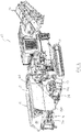
Figure 1 is a perspective view of an aggregate processing apparatus including a conveyor support structure embodying one aspect of the present invention, and shown with its conveyors and hopper flares in a deployed state; -
Figure 2 is a perspective view of the apparatus ofFigure 1 , shown with its conveyors and hopper flares in a transport (folded) state; -
Figure 3 is an end view of the apparatus ofFigure 1 , shown with its conveyors and hopper flares in the deployed state; -
Figure 4 is an end view of the apparatus ofFigure 1 , shown with its conveyors and hopper flares in the transport (folded) state; -
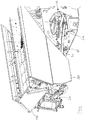
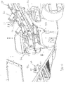
Figure 5 is a perspective view of an end of the apparatus ofFigure 1 , showing the conveyor support structure in its transport (folded) state and the hopper flares in a use state; -
Figure 6 is a perspective view of said end of the apparatus ofFigure 1 , showing the conveyor support structure in its transport (folded) state and the hopper flares in a transport (folded) state; -
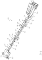
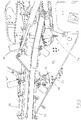
Figure 7 is a perspective view of said conveyor support structure shown in its deployed state; -
Figure 8 is a perspective view of said conveyor support structure shown in a semi-folded state intermediate said deployed state and said transport (folded) state; -
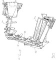
Figure 9 is a perspective view of said conveyor support structure shown in said transport (folded) state; -
Figure 10 is a perspective view of a detail of said apparatus, shown with said conveyor support structure in the deployed state and illustrating a buffer apparatus; -
Figure 11 is a perspective view of a detail of said apparatus, shown with said conveyor support structure in the transport (folded) state and illustrating a buffer apparatus; and -
Figure 12 is a perspective view of part of said conveyor support structure. - Referring now in particular to
Figures 1 to 4 of the drawings, there is shown, generally indicated as 10, an aggregate processing apparatus. Theaggregate processing apparatus 10 is configured for performing, by way of example, aggregate screening and, as such, comprises anaggregate screening plant 12. Alternatively, however, theapparatus 10 may be configured to perform one or more of a plurality of processes, such as feeding, screening, separating, crushing and/or washing, on one or more types of aggregate material, for example rocks, stones, gravel, sand and/or soil, or any other material that is quarried, mined or excavated. To this end, theapparatus 10 may include one or more material processing plants adapted to perform one or more of the foregoing processes. - Typically, the
aggregate processing apparatus 10 is mobile and comprises one or more wheels and/ortracks 11 mounted on achassis 13. Theapparatus 10 is usually self-propelled and to this end may comprise a drive system (not shown), e.g. comprising an engine, for driving the wheels/tracks 11. In any event, theapparatus 10 may include apower plant 9, which may comprise the engine and other components of the drive system and/or other apparatus for powering the apparatus, e.g. hydraulic and/or pneumatic apparatus for powering rams. - In the illustrated example, the
aggregate processing apparatus 10 includes afront conveyor 14 and aside conveyor 16 for transporting aggregate material to and/or from theapparatus 10. Afeed hopper 15 is provided above thescreening apparatus 12, the screened material being output from theapparatus 10 by one or more of theconveyors conveyors conveyors Figure 1 of the drawings and the respective use states being depicted inFigure 2 of the drawings. It will be understood that the invention is not limited to apparatus of the type shown inFigures 1 to 4 , and may for example be used with other configurations of material processing plant(s) and/or conveyor(s). - In preferred embodiments, the
hopper 15 is shaped to define a mouth 17 and comprises at least one wall section 19 arranged to guide aggregate material (not shown) into the mouth 17 when in a use state (as shown inFigures 1 and3 ). Typically, there is arespective wall section 19A, 19B at each side of thehopper 15 and at at least one end (19C) of thehopper 15. Hence, when deployed, the wall sections 19 extend at least partially around the mouth 17. In the use state, the wall sections 19 extend upwardly from the mouth 17, and preferably also extend laterally away from thehopper 15. As such, the wall sections 19 may be referred to as flares. In the use state, the height of the flares 19 can be problematic when transporting theapparatus 10. Each flare 19 is therefore operable to adopt a non-use, or transport, state in which it extends downwardly with respect to the mouth 17. Conveniently, this is achieved by configuring the flares 19 to fold with respect to thehopper 15, typically by means of a pivot mechanism. In the non-use state (Figures 2 and4 ) the flares 19 extend alongside a respective side or end of theapparatus 10, and are typically substantially parallel with the respective side or end. Advantageously, the flares 19 are located close, e.g. substantially against, the respective side or end of theapparatus 10 when folded to minimize the overall dimensions of theapparatus 10. Preferably, in respect of at least one flare 19, the arrangement is such that a gap is defined between the flare 19, when folded, and the side/end of theapparatus 10. For example, in the illustrated embodiment,flares 19A, 19B each folds against a respective side of theapparatus 10 such that agap 21 is defined between the flare and the side. This may be achieved by suitable configuration of the linkage that allows the respective flare 19 to fold. For example,flare 19A may be coupled to theapparatus 10 by one or more pivot linkages comprising first andsecond supports suitable gap 21 can be created by selection of the shape and/or size of one or both of thesupports flare 19A andapparatus 10. Actuation of theflare 19A between the use and non-use states may be effected by any suitable actuator(s), for example aram assembly 26. Similar pivoting mechanisms may be used to actuate theother flares 19B, 19C. - The
aggregate processing apparatus 10 further includes aconveyor support structure 20 embodying one aspect of the present invention. In preferred embodiments, theconveyor support structure 20 forms part of a side conveyor that is located at a side of theapparatus 10 and is deployable to extend outwardly from theapparatus 10, typically in a direction that is substantially perpendicular with the longitudinal axis of the apparatus 10 (Figures 1 and3 ), although it may alternatively extend obliquely with respect to the longitudinal axis of theapparatus 10 when deployed. InFigures 2 and4 , thesupport structure 20 is shown in a folded, or transport, state corresponding to a folded, or transport, state of the side conveyor. In the transport state, thesupport structure 20 is folded substantially against theapparatus 10. Side conveyors are typically belt-type conveyors and so thesupport structure 20 is configured to allow a conveyor belt (not shown) to be fitted thereto, as is described in more detail hereinafter. Thesupport structure 20 may alternatively form part of any other suitable conveyor, e.g. an end conveyor. - The
conveyor support structure 20 has anobverse face 31 that faces generally upwardly during use. Theobverse face 31 corresponds substantially with the obverse face of the conveyor of which thestructure 20 forms part. Where the conveyor includes a conveyor belt, the top flight of the belt runs along theobverse face 31 during use. When deployed, the conveyor may be said to lie substantially in a plane along which material is carried by the conveyor during use, and which is substantially coincident or parallel with theobverse face 31. - Referring now in addition to
Figures 7 to 9 , theconveyor support structure 20 is described in more detail. Theconveyor support 20 includes aboom structure 22 that is pivotable with respect to abase section 24 between a folded, or transport, state (Figure 9 ) and a deployed state (Figure 7 ), which correspond respectively to the transport and deployed states of the conveyor of which thesupport structure 20, in use, forms part. Thebase section 24 is mountable, preferably removably, on theapparatus 10 or other host apparatus. Alternatively, thebase section 24 may be integrally formed with theapparatus 10 or other host apparatus. - The
boom structure 22 comprises ahead section 26 and a mid-section 28, the mid-section 28 being located between thehead section 26 and thebase section 24. Thehead section 26 andmid-section 28 are pivotably coupled to one another, preferably at respective ends 29, 27. The coupling, which may comprise any suitable conventional coupling or joint, is configured to allow relative pivotable movement between thesections boom structure 22. In some embodiments, the pivotable coupling may also allow relative pivoting movement about a second axis that is substantially coincident or parallel with the longitudinal axis of theboom structure 22. - An
actuator 34 is coupled between themid section 28 and thehead section 26. Theactuator 34 typically comprises a powered linear actuator, for example a ram, preferably a double-acting ram, powered in any suitable manner, e.g. hydraulically, electrically or pneumatically. Theactuator 34 is arranged to move thehead section 26 between its folded and deployed states. Theactuator 34 is operable by a control device (not shown), which may be located on theapparatus 10, or by a wired or wireless remote controller (not shown). Theactuator 34 is pivotably coupled to the mid-section 28 and to thehead section 28. The couplings may comprise any suitable conventional coupling or joint. - The
conveyor support structure 20 may be adapted to carry a conveyor in any suitable manner. In this example, it is assumed that the conveyor comprises a conveyor belt (not shown). To this end, thehead section 26 comprises aroller support 50 at its free end, the roller support carrying aconveyor end drum 52. Thebase section 24 also includes a roller support (not visible) for carrying a conveyor end drum (not visible). One or more of thehead section 26,mid-section 28 andbase section 24 may include one or more roller supports with one or more rollers, e.g. idler rollers. In the illustrated embodiment, thehead section 26 andmid-section 28 include roller supports (not visible) for respective idler (or centre)rollers 56, which traverse the body of thehead section 26 ormid-section 28 respectively. Therollers 56 are rotatable about a respective axis that is substantially perpendicular with the longitudinal axis of therespective section respective section rollers 56 support the conveyor belt. One or more of thehead section 26,mid-section 28 andbase section 24 may include one or more roller supports (not visible) with one ormore troughing rollers 60 and, optionally, abelt retainer 62. When fitted, the conveyor belt extends between the end rollers in an endless loop, the top flight of which is shaped by the troughingrollers 60 when the conveyor is deployed. - In the preferred embodiment, either one or both of the
sections head section 26 andmid-section 28 may each comprise a respective beam, the beams being located end-to-end and pivotably coupled to one another in the manner described above. Typically, thehead section 26 andmid-section 28 are substantially disposed in a common plane in the deployed state. Typically, theboom structure 22 is substantially linear when deployed. Consequently, the top flight of the conveyor, when deployed, is substantially linear. - The mid-section 28 is pivotably coupled to the
base section 24, preferably at itsend 30,opposite end 27. The coupling, which may comprise any suitable conventional coupling or joint, is configured to allow relative pivotable movement between the mid-section 28 and thebase section 24 about at least one axis. The coupling is configured to allow the mid-section 28 to pivot between a folded state (Figures 2 ,5 ,8 and9 ) in which it is located substantially against theapparatus 10, and a deployed state in which it projects from theapparatus 10, preferably substantially perpendicularly to the longitudinal axis of theapparatus 10. As is described in further detail hereinafter, the coupling is preferably such that it allows the mid-section to pivot about first and second mutually perpendicular axes. The coupling may for example comprise a knuckle joint. - An
actuator 36 is coupled between thebase section 24 and themid section 28. Theactuator 36 typically comprises a poweredlinear actuator 36, for example a ram, preferably a double-acting ram, powered in any suitable manner, e.g. hydraulically, electrically or pneumatically. Theactuator 36 is arranged to move thehead section 28 between its folded and deployed states. Theactuator 36 is operable by a control device (not shown), which may be located on theapparatus 10, or by a wired or wireless remote controller (not shown). Theactuator 36 is pivotably coupled to thebase section 24 and to the mid-section 28, preferably at respective opposite ends 33, 35. The coupling with thebase section 24 may comprise any suitable conventional coupling or joint. Theother end 35 of theactuator 36 is coupled to the mid-section 28 by means of any suitable pivotable coupling. In preferred embodiments, asupport 32 extends between thebase section 24 and the mid-section 28 and is pivotable coupled to each to allow thesupport 32 to move with the mid-section 28 as it pivots between its folded and deployed states.End 35 of theactuator 36 is pivotably coupled directly to the support 32 (and thus indirectly coupled to the mid-section 28). This allows theactuator 36 to actuate the mid-section 28 without fouling the conveyor belt. - The
actuators actuators actuator 36 is operated (fully or partly) beforeactuator 34 is operated and, when deploying,actuator 34 is operated (fully or partly) beforeactuator 36 is operated. - It will be apparent from the foregoing that, in preferred embodiments, the
obverse face 31 of thesupport structure 20, and therefore of the conveyor, when deployed is substantially planar, but when folded comprises first and second non-coplanar parts corresponding to thehead section 26 andmid-section 28 respectively. In typical embodiments, thehead section 26 andmid-section 28 are substantially perpendicular to one another when in the folded/transport state and so the corresponding first and second parts of the obverse face are substantially perpendicular. This makes thesupport structure 20 particularly suited to folding around adjacent faces of theapparatus 10 as is described in more detail below. In alternative embodiments, thehead section 26 andmid-section 28 may be disposed obliquely with respect to one another in the transport state, typically at an obtuse angle. - Referring now to
Figures 2 ,4 ,5 and6 in particular, when thesupport structure 20 adopts its folded state, the mid-section 28 is located substantially against aside 40 of theapparatus 10, while thehead section 26 is located substantially against anend 42 of the apparatus, theend 42 being adjacent and non-parallel with theside 40. In the illustrated embodiment, theside 40 and end 42 are substantially perpendicular with one another. In such cases, it is preferred that the mid-section 28 is foldable such that, when folded, it extends substantially parallel with the longitudinal axis of the apparatus. This allows a relatively simple pivotable coupling to be provided between the mid-section 28 and thehead section 26, in particular a single axis pivot joint that traverses the boom structure substantially perpendicularly, which in turn allows a simple linear actuator to be used to effect relative movement between the mid-section and head section. - More generally, the
apparatus 10 may be said to comprise a plurality of faces, including sides, ends, upper, lower, top or bottom faces, theconveyor support structure 20 being configured to fold or wrap around first and second adjacent non-parallel faces. Typically, one of the faces is a side or end of theapparatus 10, the other being an adjacent end or side respectively. Alternatively, one of the faces may be a side or end, the other being an adjacent top or upper surface, or an adjacent underside or lower face. - For a given location of the
base section 24, the length of the mid-section 28 andhead section 26 may be selected to suit the dimensions of theapparatus 10. Alternatively, for a desired length ofboom structure 32, the location of thebase section 24 may be chosen accordingly. - The configuration of the respective pivotable couplings between the base section and the mid-section and between the mid-section and the head section may be selected to suit the relative position of the first and second faces (e.g. side, end, upper or lower etc.) and the relative orientation between the faces (e.g. perpendicular, oblique etc.).
- In preferred embodiments, the
boom structure 32 is foldable around first and second adjacent faces that are substantially perpendicular to one another, in which case it is preferred that the mid-section 28 andhead section 26, when folded, extend substantially parallel with a respective one of the three main orthogonal axes of theapparatus 10. For example, where the first face is a side or end and the second face is an end or side, respectively, then the mid-section 28 andhead section 26, when folded, preferably extend substantially parallel with the longitudinal or transverse axis of theapparatus 10, as applicable. Alternatively, where one of the faces is a top face, then one or other of the mid-section or head section preferably extends substantially orthogonally to both the longitudinal and transverse axes of theapparatus 10. - In preferred embodiments, when in the folded state, the mid-section is oriented such that its
obverse face 31, and consequently the corresponding obverse face of the conveyor, is substantially parallel with the face of theapparatus 10 against which it is folded. It is particularly preferred that the mid-section 28 is folded such that itsobverse face 31, and consequently the obverse face of the conveyor, faces towards the face of theapparatus 10 against which it is folded. Similarly, when folded, it is preferred thathead section 26 is oriented such that itsobverse face 31, and consequently the corresponding obverse face of the conveyor, is substantially parallel with the face of theapparatus 10 against which it is folded. It is particularly preferred that thehead section 26 is folded such that itsobverse face 31, and consequently the obverse face of the conveyor, faces towards the face of theapparatus 10 against which it is folded. - When the mid-section 28 or
head section 26 are folded substantially against the respective face of theapparatus 10, there need not necessarily be contact between the mid-section/head section and the respective face of theapparatus 10. Rather, the mid-section and preferably also the head section are, when folded, located adjacent to and extend alongside the respective face of theapparatus 10, preferably running substantially parallel with the respective face and advantageously in close proximity with the respective face. - In preferred embodiments where the obverse face of the mid-section and preferably also the head section face the
apparatus 10, parts of theconveyor support structure 20 and/or conveyor components that project from the obverse face of the conveyor (e.g. the troughingrollers 60 and the retainers 62) may be positioned such that they project into, when folded, recesses orcavities 44 formed in the body of theapparatus 10. This reduces the extent to which the folded conveyor projects laterally from theapparatus 10. - Preferably, at least one and optionally both of the mid-section 28 and
head section 26 carries a stop device 46 (Figures 10 to 12 ) projecting from thestructure 20 such that it engages with the respective face of theapparatus 10 when thestructure 20 is folded. Thestop device 46 is dimensioned and positioned to prevent other parts (in particular the troughing rollers 60) of thestructure 20, and conveyor of which thestructure 20 is part, from engaging with theapparatus 10 and so protects them from damage. For example, fromFigures 10 to 12 it can be seen that thestop device 46 is substantially aligned with the troughingrollers 60 on one side of thestructure 20 and is dimensioned to project further from the structure than theroller 60 do. Preferably, the respective face of theapparatus 10 carries asocket 48 for receiving thestop device 46 when thestructure 20 is folded. Advantageously, the free end of the stop device carries a roller 51, thesocket 48 being shaped and dimensioned to receive the roller 51 (preferably including aramp 53 for this purpose), whereby during folding of thestructure 20, engagement of the roller 51 with thesocket 48, and in particular theramp 53, causes thestop device 46 to be guided into thesocket 48. Preferably, a locking mechanism 55 is provided for releasably securing thestop device 46 in thesocket 48 and so helping to maintain thestructure 20 in its folded position. - In preferred embodiments, the
support structure 20 is positioned on theapparatus 10 such that, when folded, thehead section 26 and/or the mid-section 28 is located below thehopper 15. For example, in the illustrated embodiment, thebase section 24 is located atside 40 of theapparatus 10 and thesupport structure 20 is configured such that the mid-section 28, when folded, extends alongside 40 beneathhopper 15. Thehead section 26, when folded, also extends below thehopper 15 at theend 42 in this instance. Alternatively, thebase section 24 may located atend 42 of theapparatus 10 and thesupport structure 20 configured such that the mid-section 28, when folded, extends alongend 42 beneathhopper 15, thehead section 26, when folded, extending below thehopper 15 at theside 40. In either case, advantageously the arrangement is such that part of the boom structure 22 (and in particular at least part of the mid-section and/or at least part of the head section) is located between the respective flare 19, when folded, and theapparatus 10. For example, in the illustrated embodiment, the mid-section 28 extends through thegap 21 betweenflare 19A and theside 40. This causes the overall width of theapparatus 10 in the transport state to be narrower than the alternative arrangement in which the respective flare(s) is between the relevant part(s) of theboom structure 22 and theapparatus 10 when folded since, in the preferred arrangement, parts of the conveyor/boom structure can fit into recesses andcavities 44. - This preferred aspect of the invention is not limited to the flares of the hopper and, in alternative embodiments, the boom structure may be arranged to extend behind one or more foldable sections of any component of the
apparatus 10. - In preferred embodiments, the or each
respective idler roller 56 of at least part of theboom structure 22, for example thehead section 26 and/or the mid-section 28, is recessed with respect to thebody 70 of theboom structure 22. The body typically comprises a frame (as illustrated) or a beam. Referring in particular toFigure 7 , the preferred arrangement is such that only part of eachroller 56 projects beyond theobverse surface 31 of thebody 70, i.e. that at least part of eachroller 56 is recessed with respect to theobverse surface 31 of thebody 70. Conveniently, this is achieved by mounting eachroller 56 in a cavity formed in thebody 70. Where thebody 70 comprises a frame, thecavity 74 may conveniently be formed between spaced apart frame members, for example substantiallyparallel frame members 72 which, in the illustrated embodiment, define respective sides of thebody 70. Typically, the rotational axis of each roller is recessed with respect to theobverse face 31 of thebody 70. For example, an axle or bearings for theroller 56 may extend between, or otherwise be located between, the walls of the cavity to create a transverse rotational axis for the roller. It is preferred that eachroller 56 is associated with a respective cavity formed in thebody 70, the inter-cavity regions of the body comprisingsupport members 76. The recessedrollers 56 help to reduce the height of the boom structure along at least part or parts of its length and this makes it easier to fit the boom structure against theapparatus 10 when folded. This is especially useful in preferred embodiments where theboom structure 22 extends behind one or more folded flares 19. - It will be understood that the invention is not limited to side conveyors. More generally, a conveyor support structure is suitable for use with a conveyor that is deployable between a deployed state, in which it extends outwardly from a host apparatus, and a folded state, in which it is folded substantially against the host apparatus. For example, conveyor support structures may be used with conveyors located at an end of the
apparatus 10. - The invention is not limited to the embodiment described herein which may be modified or varied without departing from the scope of the invention.
Claims (10)
- An aggregate processing apparatus (10) comprising a conveyor support structure (20) comprising a base section (24) located at a first face of said apparatus, a mid-section (28) pivotably coupled to said base section and a head section (26) pivotably coupled to said mid-section, wherein said conveyor support structure is operable between a deployed state and a transport state, characterised in that said first face of said apparatus is a side (40) of said apparatus, and in said deployed state said mid-section and said head section projects from said side, and in said transport state said mid-section is folded to extend across said side, and to extend substantially parallel with the longitudinal axis of the apparatus (10), and said head section is folded with respect to said mid-section to extend across an end (42) of the apparatus, said end being adjacent and non-parallel with said side.
- An apparatus as claimed in claim 1, wherein, in said transport state, said mid-section (28) and preferably also said head section (26) are folded substantially against said side (40) and end (42) respectively.
- An apparatus as claimed in any preceding claim, wherein said conveyor support structure (20) is configured such that in said transport state said mid-section (28) and said head section (26) are substantially perpendicularly disposed with respect to one another.
- An apparatus as claimed in any preceding claim, wherein said conveyor support structure (20) is configured such that in said deployed state the respective obverse face of said mid-section (28) and said head section (26) are substantially co-planar or parallel, and in said transport state said respective obverse faces are non-coplanar and non-parallel.
- An apparatus as claimed in any preceding claim, wherein said conveyor support structure (20) is configured such that in said transport state the obverse face of said mid-section (28) and preferably also of said head section (26) face said side (40) and end (42) respectively.
- An apparatus as claimed in claim 5, wherein at least one of said mid-section (28) and said head section (26) includes at least one part (46) that projects from the respective obverse face, said conveyor support structure (20) being configured such that, in said transport state, said at least one part projects in to a respective one of at least one recess or cavity (48) formed in said apparatus (10).
- An apparatus as claimed in any preceding claim, wherein at least one of the head section (26) and mid-section (28) carries at least one roller (56) recessed with respect to the body (70) of the head section (26) or mid-section (28) respectively such that only part of said at least one roller projects beyond the obverse surface of the body.
- An apparatus as claimed in any preceding claim, wherein said apparatus includes at least one foldable section (19A) foldable into and out of a transport state in which it extends across, and is preferably disposed substantially parallel with, said side (40) to define a gap (21) therebetween, wherein said conveyor support structure (20) is configured such that at least part of said mid-section (28) in its transport state is located in said gap.
- An apparatus as claimed in any preceding claim, wherein said apparatus includes at least one foldable section (19C) foldable into and out of a transport state in which it extends across, and is preferably disposed substantially parallel with, said end (42) to define a gap therebetween, wherein said conveyor support structure (20) is configured such that at least part of said head section (26) in its transport state is located in said gap.
- An apparatus as claimed in claim 8 or 9, wherein said at least one foldable section (19A, 19C) comprises at least part of a hopper wall.
Priority Applications (1)
| Application Number | Priority Date | Filing Date | Title |
|---|---|---|---|
| PL12778306T PL2768750T3 (en) | 2011-10-20 | 2012-10-19 | Foldable conveyor support structure with wrap-around capability |
Applications Claiming Priority (2)
| Application Number | Priority Date | Filing Date | Title |
|---|---|---|---|
| GBGB1118144.3A GB201118144D0 (en) | 2011-10-20 | 2011-10-20 | Foldable conveyor support structure with wraparound capability |
| PCT/EP2012/070830 WO2013057300A2 (en) | 2011-10-20 | 2012-10-19 | Foldable conveyor support structure with wrap-around capability |
Publications (3)
| Publication Number | Publication Date |
|---|---|
| EP2768750A2 EP2768750A2 (en) | 2014-08-27 |
| EP2768750B1 true EP2768750B1 (en) | 2020-12-09 |
| EP2768750B8 EP2768750B8 (en) | 2021-03-10 |
Family
ID=45220017
Family Applications (1)
| Application Number | Title | Priority Date | Filing Date |
|---|---|---|---|
| EP12778306.6A Active EP2768750B8 (en) | 2011-10-20 | 2012-10-19 | Foldable conveyor support structure with wrap-around capability |
Country Status (7)
| Country | Link |
|---|---|
| US (1) | US9302852B2 (en) |
| EP (1) | EP2768750B8 (en) |
| AU (1) | AU2012324783B2 (en) |
| CA (1) | CA2851674C (en) |
| GB (2) | GB201118144D0 (en) |
| PL (1) | PL2768750T3 (en) |
| WO (1) | WO2013057300A2 (en) |
Families Citing this family (8)
| Publication number | Priority date | Publication date | Assignee | Title |
|---|---|---|---|---|
| US9376260B2 (en) * | 2014-02-06 | 2016-06-28 | Metso Minerals, Inc. | Conveyor body and mobile mineral material processing plant |
| DE102015104498B4 (en) | 2015-03-25 | 2022-05-25 | Kleemann Gmbh | Folding mechanism for a conveyor |
| US20180161779A1 (en) * | 2015-05-29 | 2018-06-14 | Smoracy, Llc | Discharge System for a Waste Processing Machine and Method Thereof |
| EP3768621B1 (en) * | 2018-03-23 | 2022-04-20 | Metso Outotec Finland Oy | Movable material processing apparatus comprising a foldable conveyor |
| GB2574896B (en) * | 2018-06-22 | 2021-05-26 | Terex Gb Ltd | Improvements in and relating to material processing apparatus |
| CN108940546B (en) * | 2018-08-31 | 2024-06-21 | 河南山川环保科技有限公司 | Vehicle-mounted movable crushing station |
| DE102019118058A1 (en) * | 2019-07-04 | 2021-01-07 | Kleemann Gmbh | Feed hopper for a material processing device |
| AT526271A1 (en) * | 2023-01-23 | 2023-11-15 | Rubble Master Hmh Gmbh | Conveyor for a mobile material processing machine |
Family Cites Families (24)
| Publication number | Priority date | Publication date | Assignee | Title |
|---|---|---|---|---|
| US4598875A (en) * | 1978-09-11 | 1986-07-08 | Allis-Chalmers Corporation | Portable crushing and screening plant |
| AR226941A1 (en) | 1981-06-12 | 1982-08-31 | Rossi Lionello | CONTINUOUS BELT, FOLDING OR SINGLE CONVEYOR TO BE MOUNTED ON THE SIDE OF A SELF-CONCRETE MIXER OR THE LIKE |
| EP0424591A1 (en) | 1989-10-23 | 1991-05-02 | FERRIERE BELLOLI & Co. | Quick telescopic, extensible, movable belt conveyor with three rotational degrees of freedom for solid or viscoplastic materials, particularly for use in cement mixer or truck mixer |
| US5294065A (en) * | 1993-01-29 | 1994-03-15 | Portec, Inc. | Portable screening/dosing/mixing plant |
| US5419502A (en) * | 1993-04-14 | 1995-05-30 | Wood Technology, Inc. | Tub grinder systems and methods for comminuting waste wood |
| ATE174821T1 (en) | 1993-09-07 | 1999-01-15 | Malachy James Rafferty | MOBILE SYSTEM FOR THE TREATMENT OF AGGREGATE MATERIAL |
| GB2283721A (en) * | 1993-11-11 | 1995-05-17 | Neill Patrick O | Foldable belt conveyor |
| FR2712575B1 (en) | 1993-11-18 | 1998-06-05 | Thenaud Fils Ets | Conveyor belt, especially for concrete mixer truck. |
| DE19781758B4 (en) * | 1996-05-03 | 2004-12-23 | Extec Screens And Crushers Ltd., Swadlincote | Self-propelled material processing device |
| US6095320A (en) * | 1998-08-26 | 2000-08-01 | Prairie Machine & Parts Mfg., Ltd. | Conveyor deployment system |
| GB0023866D0 (en) * | 2000-09-29 | 2000-11-15 | Extec Ind Plc | Bulk material processing apparatus |
| US7464889B2 (en) * | 2002-06-06 | 2008-12-16 | Johnson Crushers International | Mobile rock crushing plant |
| GB0219563D0 (en) * | 2002-08-22 | 2002-10-02 | Extec Ind Plc | Mobile 3-part crusher assembly |
| GB0408594D0 (en) * | 2004-04-16 | 2004-05-19 | Extec Screens & Crushers Ltd | Crusher apparatus |
| US7264104B2 (en) * | 2005-03-11 | 2007-09-04 | Johnson Crushers International | Crusher in-feed conveyor method and apparatus |
| US7424943B2 (en) | 2005-10-20 | 2008-09-16 | Superior Industries, Llc | Portable low profile drive-over truck dump conveyor system |
| EP2001606A2 (en) * | 2006-02-16 | 2008-12-17 | Aughey Research and Designs Limited | A material screening apparatus |
| US7461746B1 (en) * | 2006-06-19 | 2008-12-09 | Astec Industries, Inc. | Portable screening/washing plant with scrubbing mill |
| JP5466867B2 (en) * | 2008-05-28 | 2014-04-09 | 株式会社小松製作所 | Self-propelled crusher |
| CN201353523Y (en) | 2009-02-05 | 2009-12-02 | 郑州一帆机械设备有限公司 | Portable crushing station and soil-discharging belt mechanism thereof |
| NL2004156C2 (en) * | 2010-01-27 | 2011-07-28 | Mark Galien | REDUCTION DEVICE AND METHOD FOR REDUCING MATERIAL. |
| CN103415347B (en) * | 2011-02-15 | 2015-02-18 | 美特索矿物公司 | Mobile handling equipment for mineral material handling |
| US8591155B2 (en) * | 2011-03-17 | 2013-11-26 | Timothy Lawlor | Transport system for heavy-duty equipment |
| GB2507766B (en) * | 2012-11-08 | 2018-02-14 | Terex Gb Ltd | Folding mechanism |
-
2011
- 2011-10-20 GB GBGB1118144.3A patent/GB201118144D0/en not_active Ceased
-
2012
- 2012-10-19 PL PL12778306T patent/PL2768750T3/en unknown
- 2012-10-19 CA CA2851674A patent/CA2851674C/en active Active
- 2012-10-19 GB GB1407510.5A patent/GB2509291B/en active Active
- 2012-10-19 EP EP12778306.6A patent/EP2768750B8/en active Active
- 2012-10-19 AU AU2012324783A patent/AU2012324783B2/en active Active
- 2012-10-19 US US14/352,378 patent/US9302852B2/en active Active
- 2012-10-19 WO PCT/EP2012/070830 patent/WO2013057300A2/en not_active Ceased
Non-Patent Citations (1)
| Title |
|---|
| None * |
Also Published As
| Publication number | Publication date |
|---|---|
| EP2768750B8 (en) | 2021-03-10 |
| GB201118144D0 (en) | 2011-11-30 |
| AU2012324783B2 (en) | 2017-09-14 |
| PL2768750T3 (en) | 2021-06-28 |
| GB2509291A (en) | 2014-06-25 |
| US20140367222A1 (en) | 2014-12-18 |
| CA2851674C (en) | 2019-07-23 |
| CA2851674A1 (en) | 2013-04-25 |
| WO2013057300A2 (en) | 2013-04-25 |
| US9302852B2 (en) | 2016-04-05 |
| EP2768750A2 (en) | 2014-08-27 |
| AU2012324783A1 (en) | 2014-05-22 |
| GB201407510D0 (en) | 2014-06-11 |
| GB2509291B (en) | 2018-01-17 |
| WO2013057300A3 (en) | 2013-07-04 |
Similar Documents
| Publication | Publication Date | Title |
|---|---|---|
| CA2851674C (en) | Foldable conveyor support structure with wrap-around capability | |
| CA2680081C (en) | Foldable framework for auxiliary conveyor | |
| US20140224906A1 (en) | Material processing apparatus with multi-mode feed conveyor assembly | |
| AU2014200246B2 (en) | Material processing apparatus with deployable feed conveyor | |
| AU2011359056B2 (en) | Movable process device for mineral material processing | |
| CN109205334B (en) | Tracked radial stacker with wheels | |
| EP2664492B1 (en) | Folding mechanism with locking function | |
| WO2013068589A1 (en) | Locking system for hopper flares | |
| US9539578B2 (en) | Main frame for mobile bulk processing apparatus | |
| US20140124330A1 (en) | Foldable conveyor support structure | |
| CA3019691A1 (en) | Material processing apparatus | |
| EP4001181B1 (en) | Foldable conveyor with deployable skirting | |
| JP2012218870A (en) | Conveyor | |
| KR101184963B1 (en) | Apparatus for moving conveyer belt |
Legal Events
| Date | Code | Title | Description |
|---|---|---|---|
| PUAI | Public reference made under article 153(3) epc to a published international application that has entered the european phase |
Free format text: ORIGINAL CODE: 0009012 |
|
| 17P | Request for examination filed |
Effective date: 20140520 |
|
| AK | Designated contracting states |
Kind code of ref document: A2 Designated state(s): AL AT BE BG CH CY CZ DE DK EE ES FI FR GB GR HR HU IE IS IT LI LT LU LV MC MK MT NL NO PL PT RO RS SE SI SK SM TR |
|
| DAX | Request for extension of the european patent (deleted) | ||
| STAA | Information on the status of an ep patent application or granted ep patent |
Free format text: STATUS: EXAMINATION IS IN PROGRESS |
|
| 17Q | First examination report despatched |
Effective date: 20190201 |
|
| GRAP | Despatch of communication of intention to grant a patent |
Free format text: ORIGINAL CODE: EPIDOSNIGR1 |
|
| STAA | Information on the status of an ep patent application or granted ep patent |
Free format text: STATUS: GRANT OF PATENT IS INTENDED |
|
| INTG | Intention to grant announced |
Effective date: 20200703 |
|
| GRAS | Grant fee paid |
Free format text: ORIGINAL CODE: EPIDOSNIGR3 |
|
| GRAA | (expected) grant |
Free format text: ORIGINAL CODE: 0009210 |
|
| STAA | Information on the status of an ep patent application or granted ep patent |
Free format text: STATUS: THE PATENT HAS BEEN GRANTED |
|
| AK | Designated contracting states |
Kind code of ref document: B1 Designated state(s): AL AT BE BG CH CY CZ DE DK EE ES FI FR GB GR HR HU IE IS IT LI LT LU LV MC MK MT NL NO PL PT RO RS SE SI SK SM TR |
|
| REG | Reference to a national code |
Ref country code: GB Ref legal event code: FG4D |
|
| REG | Reference to a national code |
Ref country code: AT Ref legal event code: REF Ref document number: 1343217 Country of ref document: AT Kind code of ref document: T Effective date: 20201215 Ref country code: CH Ref legal event code: EP |
|
| REG | Reference to a national code |
Ref country code: DE Ref legal event code: R096 Ref document number: 602012073652 Country of ref document: DE |
|
| RBV | Designated contracting states (corrected) |
Designated state(s): AL AT BE BG CH CY CZ DE DK EE ES FI FR GR HR HU IE IS IT LI LT LU LV MC MK MT NL NO PL PT RO RS SE SI SK SM TR |
|
| REG | Reference to a national code |
Ref country code: IE Ref legal event code: FG4D |
|
| REG | Reference to a national code |
Ref country code: CH Ref legal event code: PK Free format text: BERICHTIGUNG B8 |
|
| REG | Reference to a national code |
Ref country code: FI Ref legal event code: FGE |
|
| REG | Reference to a national code |
Ref country code: SE Ref legal event code: TRGR |
|
| PG25 | Lapsed in a contracting state [announced via postgrant information from national office to epo] |
Ref country code: GR Free format text: LAPSE BECAUSE OF FAILURE TO SUBMIT A TRANSLATION OF THE DESCRIPTION OR TO PAY THE FEE WITHIN THE PRESCRIBED TIME-LIMIT Effective date: 20210310 Ref country code: RS Free format text: LAPSE BECAUSE OF FAILURE TO SUBMIT A TRANSLATION OF THE DESCRIPTION OR TO PAY THE FEE WITHIN THE PRESCRIBED TIME-LIMIT Effective date: 20201209 Ref country code: NO Free format text: LAPSE BECAUSE OF FAILURE TO SUBMIT A TRANSLATION OF THE DESCRIPTION OR TO PAY THE FEE WITHIN THE PRESCRIBED TIME-LIMIT Effective date: 20210309 |
|
| PG25 | Lapsed in a contracting state [announced via postgrant information from national office to epo] |
Ref country code: LV Free format text: LAPSE BECAUSE OF FAILURE TO SUBMIT A TRANSLATION OF THE DESCRIPTION OR TO PAY THE FEE WITHIN THE PRESCRIBED TIME-LIMIT Effective date: 20201209 Ref country code: BG Free format text: LAPSE BECAUSE OF FAILURE TO SUBMIT A TRANSLATION OF THE DESCRIPTION OR TO PAY THE FEE WITHIN THE PRESCRIBED TIME-LIMIT Effective date: 20210309 |
|
| REG | Reference to a national code |
Ref country code: NL Ref legal event code: MP Effective date: 20201209 |
|
| PG25 | Lapsed in a contracting state [announced via postgrant information from national office to epo] |
Ref country code: HR Free format text: LAPSE BECAUSE OF FAILURE TO SUBMIT A TRANSLATION OF THE DESCRIPTION OR TO PAY THE FEE WITHIN THE PRESCRIBED TIME-LIMIT Effective date: 20201209 Ref country code: NL Free format text: LAPSE BECAUSE OF FAILURE TO SUBMIT A TRANSLATION OF THE DESCRIPTION OR TO PAY THE FEE WITHIN THE PRESCRIBED TIME-LIMIT Effective date: 20201209 |
|
| REG | Reference to a national code |
Ref country code: LT Ref legal event code: MG9D |
|
| PG25 | Lapsed in a contracting state [announced via postgrant information from national office to epo] |
Ref country code: LT Free format text: LAPSE BECAUSE OF FAILURE TO SUBMIT A TRANSLATION OF THE DESCRIPTION OR TO PAY THE FEE WITHIN THE PRESCRIBED TIME-LIMIT Effective date: 20201209 Ref country code: PT Free format text: LAPSE BECAUSE OF FAILURE TO SUBMIT A TRANSLATION OF THE DESCRIPTION OR TO PAY THE FEE WITHIN THE PRESCRIBED TIME-LIMIT Effective date: 20210409 Ref country code: RO Free format text: LAPSE BECAUSE OF FAILURE TO SUBMIT A TRANSLATION OF THE DESCRIPTION OR TO PAY THE FEE WITHIN THE PRESCRIBED TIME-LIMIT Effective date: 20201209 Ref country code: SK Free format text: LAPSE BECAUSE OF FAILURE TO SUBMIT A TRANSLATION OF THE DESCRIPTION OR TO PAY THE FEE WITHIN THE PRESCRIBED TIME-LIMIT Effective date: 20201209 Ref country code: SM Free format text: LAPSE BECAUSE OF FAILURE TO SUBMIT A TRANSLATION OF THE DESCRIPTION OR TO PAY THE FEE WITHIN THE PRESCRIBED TIME-LIMIT Effective date: 20201209 Ref country code: EE Free format text: LAPSE BECAUSE OF FAILURE TO SUBMIT A TRANSLATION OF THE DESCRIPTION OR TO PAY THE FEE WITHIN THE PRESCRIBED TIME-LIMIT Effective date: 20201209 |
|
| REG | Reference to a national code |
Ref country code: DE Ref legal event code: R097 Ref document number: 602012073652 Country of ref document: DE |
|
| PG25 | Lapsed in a contracting state [announced via postgrant information from national office to epo] |
Ref country code: IS Free format text: LAPSE BECAUSE OF FAILURE TO SUBMIT A TRANSLATION OF THE DESCRIPTION OR TO PAY THE FEE WITHIN THE PRESCRIBED TIME-LIMIT Effective date: 20210409 |
|
| PLBE | No opposition filed within time limit |
Free format text: ORIGINAL CODE: 0009261 |
|
| STAA | Information on the status of an ep patent application or granted ep patent |
Free format text: STATUS: NO OPPOSITION FILED WITHIN TIME LIMIT |
|
| PG25 | Lapsed in a contracting state [announced via postgrant information from national office to epo] |
Ref country code: IT Free format text: LAPSE BECAUSE OF FAILURE TO SUBMIT A TRANSLATION OF THE DESCRIPTION OR TO PAY THE FEE WITHIN THE PRESCRIBED TIME-LIMIT Effective date: 20201209 Ref country code: AL Free format text: LAPSE BECAUSE OF FAILURE TO SUBMIT A TRANSLATION OF THE DESCRIPTION OR TO PAY THE FEE WITHIN THE PRESCRIBED TIME-LIMIT Effective date: 20201209 |
|
| 26N | No opposition filed |
Effective date: 20210910 |
|
| PG25 | Lapsed in a contracting state [announced via postgrant information from national office to epo] |
Ref country code: ES Free format text: LAPSE BECAUSE OF FAILURE TO SUBMIT A TRANSLATION OF THE DESCRIPTION OR TO PAY THE FEE WITHIN THE PRESCRIBED TIME-LIMIT Effective date: 20201209 Ref country code: DK Free format text: LAPSE BECAUSE OF FAILURE TO SUBMIT A TRANSLATION OF THE DESCRIPTION OR TO PAY THE FEE WITHIN THE PRESCRIBED TIME-LIMIT Effective date: 20201209 Ref country code: SI Free format text: LAPSE BECAUSE OF FAILURE TO SUBMIT A TRANSLATION OF THE DESCRIPTION OR TO PAY THE FEE WITHIN THE PRESCRIBED TIME-LIMIT Effective date: 20201209 |
|
| REG | Reference to a national code |
Ref country code: CH Ref legal event code: PL |
|
| PG25 | Lapsed in a contracting state [announced via postgrant information from national office to epo] |
Ref country code: IS Free format text: LAPSE BECAUSE OF FAILURE TO SUBMIT A TRANSLATION OF THE DESCRIPTION OR TO PAY THE FEE WITHIN THE PRESCRIBED TIME-LIMIT Effective date: 20210409 |
|
| PG25 | Lapsed in a contracting state [announced via postgrant information from national office to epo] |
Ref country code: MC Free format text: LAPSE BECAUSE OF FAILURE TO SUBMIT A TRANSLATION OF THE DESCRIPTION OR TO PAY THE FEE WITHIN THE PRESCRIBED TIME-LIMIT Effective date: 20201209 |
|
| PG25 | Lapsed in a contracting state [announced via postgrant information from national office to epo] |
Ref country code: LU Free format text: LAPSE BECAUSE OF NON-PAYMENT OF DUE FEES Effective date: 20211019 |
|
| PG25 | Lapsed in a contracting state [announced via postgrant information from national office to epo] |
Ref country code: LI Free format text: LAPSE BECAUSE OF NON-PAYMENT OF DUE FEES Effective date: 20211031 Ref country code: CH Free format text: LAPSE BECAUSE OF NON-PAYMENT OF DUE FEES Effective date: 20211031 |
|
| PG25 | Lapsed in a contracting state [announced via postgrant information from national office to epo] |
Ref country code: HU Free format text: LAPSE BECAUSE OF FAILURE TO SUBMIT A TRANSLATION OF THE DESCRIPTION OR TO PAY THE FEE WITHIN THE PRESCRIBED TIME-LIMIT; INVALID AB INITIO Effective date: 20121019 Ref country code: CY Free format text: LAPSE BECAUSE OF FAILURE TO SUBMIT A TRANSLATION OF THE DESCRIPTION OR TO PAY THE FEE WITHIN THE PRESCRIBED TIME-LIMIT Effective date: 20201209 |
|
| P01 | Opt-out of the competence of the unified patent court (upc) registered |
Effective date: 20230530 |
|
| PG25 | Lapsed in a contracting state [announced via postgrant information from national office to epo] |
Ref country code: MK Free format text: LAPSE BECAUSE OF FAILURE TO SUBMIT A TRANSLATION OF THE DESCRIPTION OR TO PAY THE FEE WITHIN THE PRESCRIBED TIME-LIMIT Effective date: 20201209 |
|
| PG25 | Lapsed in a contracting state [announced via postgrant information from national office to epo] |
Ref country code: MT Free format text: LAPSE BECAUSE OF FAILURE TO SUBMIT A TRANSLATION OF THE DESCRIPTION OR TO PAY THE FEE WITHIN THE PRESCRIBED TIME-LIMIT Effective date: 20201209 |
|
| REG | Reference to a national code |
Ref country code: AT Ref legal event code: UEP Ref document number: 1343217 Country of ref document: AT Kind code of ref document: T Effective date: 20201209 |
|
| PGFP | Annual fee paid to national office [announced via postgrant information from national office to epo] |
Ref country code: PL Payment date: 20250918 Year of fee payment: 14 |
|
| PG25 | Lapsed in a contracting state [announced via postgrant information from national office to epo] |
Ref country code: TR Free format text: LAPSE BECAUSE OF FAILURE TO SUBMIT A TRANSLATION OF THE DESCRIPTION OR TO PAY THE FEE WITHIN THE PRESCRIBED TIME-LIMIT Effective date: 20201209 |
|
| PGFP | Annual fee paid to national office [announced via postgrant information from national office to epo] |
Ref country code: DE Payment date: 20251021 Year of fee payment: 14 |
|
| PGFP | Annual fee paid to national office [announced via postgrant information from national office to epo] |
Ref country code: AT Payment date: 20251022 Year of fee payment: 14 |
|
| PGFP | Annual fee paid to national office [announced via postgrant information from national office to epo] |
Ref country code: FI Payment date: 20251028 Year of fee payment: 14 |
|
| PGFP | Annual fee paid to national office [announced via postgrant information from national office to epo] |
Ref country code: FR Payment date: 20251030 Year of fee payment: 14 |
|
| PGFP | Annual fee paid to national office [announced via postgrant information from national office to epo] |
Ref country code: BE Payment date: 20251021 Year of fee payment: 14 |
|
| PGFP | Annual fee paid to national office [announced via postgrant information from national office to epo] |
Ref country code: SE Payment date: 20251021 Year of fee payment: 14 |
|
| PGFP | Annual fee paid to national office [announced via postgrant information from national office to epo] |
Ref country code: IE Payment date: 20251024 Year of fee payment: 14 Ref country code: CZ Payment date: 20251013 Year of fee payment: 14 |