EP2768679B1 - Micro motion poppet valve assembly for delivery of ink with large pigment particles to a writing nib and writing instrument comprising same - Google Patents
Micro motion poppet valve assembly for delivery of ink with large pigment particles to a writing nib and writing instrument comprising same Download PDFInfo
- Publication number
- EP2768679B1 EP2768679B1 EP12816570.1A EP12816570A EP2768679B1 EP 2768679 B1 EP2768679 B1 EP 2768679B1 EP 12816570 A EP12816570 A EP 12816570A EP 2768679 B1 EP2768679 B1 EP 2768679B1
- Authority
- EP
- European Patent Office
- Prior art keywords
- valve
- nib
- writing
- ink
- valve assembly
- Prior art date
- Legal status (The legal status is an assumption and is not a legal conclusion. Google has not performed a legal analysis and makes no representation as to the accuracy of the status listed.)
- Not-in-force
Links
- 239000002245 particle Substances 0.000 title claims description 28
- 239000000049 pigment Substances 0.000 title claims description 28
- 239000000976 ink Substances 0.000 claims description 104
- 238000001746 injection moulding Methods 0.000 claims description 5
- 238000004891 communication Methods 0.000 claims description 4
- 239000012530 fluid Substances 0.000 claims description 4
- 239000000463 material Substances 0.000 claims description 4
- 239000012815 thermoplastic material Substances 0.000 claims description 4
- 239000004033 plastic Substances 0.000 claims 1
- 239000000203 mixture Substances 0.000 description 17
- 239000007788 liquid Substances 0.000 description 9
- 239000003550 marker Substances 0.000 description 6
- 229920003031 santoprene Polymers 0.000 description 6
- 238000007789 sealing Methods 0.000 description 5
- 229920002725 thermoplastic elastomer Polymers 0.000 description 4
- -1 for example Substances 0.000 description 3
- 239000000758 substrate Substances 0.000 description 3
- 230000009471 action Effects 0.000 description 2
- 239000003000 extruded plastic Substances 0.000 description 2
- 229910001369 Brass Inorganic materials 0.000 description 1
- 229920000339 Marlex Polymers 0.000 description 1
- 239000004677 Nylon Substances 0.000 description 1
- 239000004698 Polyethylene Substances 0.000 description 1
- 239000004743 Polypropylene Substances 0.000 description 1
- 229920009815 Santoprene 101-73 Polymers 0.000 description 1
- 239000000853 adhesive Substances 0.000 description 1
- 230000001070 adhesive effect Effects 0.000 description 1
- 238000005054 agglomeration Methods 0.000 description 1
- 230000002776 aggregation Effects 0.000 description 1
- XAGFODPZIPBFFR-UHFFFAOYSA-N aluminium Chemical compound [Al] XAGFODPZIPBFFR-UHFFFAOYSA-N 0.000 description 1
- 229910052782 aluminium Inorganic materials 0.000 description 1
- 230000000712 assembly Effects 0.000 description 1
- 238000000429 assembly Methods 0.000 description 1
- 239000010951 brass Substances 0.000 description 1
- 230000006835 compression Effects 0.000 description 1
- 238000007906 compression Methods 0.000 description 1
- 239000002989 correction material Substances 0.000 description 1
- 230000003247 decreasing effect Effects 0.000 description 1
- 230000000994 depressogenic effect Effects 0.000 description 1
- 238000006073 displacement reaction Methods 0.000 description 1
- 230000000694 effects Effects 0.000 description 1
- 229920001971 elastomer Polymers 0.000 description 1
- 239000000806 elastomer Substances 0.000 description 1
- 238000005516 engineering process Methods 0.000 description 1
- 230000009969 flowable effect Effects 0.000 description 1
- 230000005484 gravity Effects 0.000 description 1
- 229920001903 high density polyethylene Polymers 0.000 description 1
- 239000004700 high-density polyethylene Substances 0.000 description 1
- 230000002401 inhibitory effect Effects 0.000 description 1
- 230000007246 mechanism Effects 0.000 description 1
- 238000012986 modification Methods 0.000 description 1
- 230000004048 modification Effects 0.000 description 1
- 229920001778 nylon Polymers 0.000 description 1
- 229920000573 polyethylene Polymers 0.000 description 1
- 229920001155 polypropylene Polymers 0.000 description 1
- 239000004800 polyvinyl chloride Substances 0.000 description 1
- 238000009877 rendering Methods 0.000 description 1
- 238000010008 shearing Methods 0.000 description 1
- 239000000126 substance Substances 0.000 description 1
- 239000000725 suspension Substances 0.000 description 1
- 229920001169 thermoplastic Polymers 0.000 description 1
- 239000004416 thermosoftening plastic Substances 0.000 description 1
- 230000007704 transition Effects 0.000 description 1
- 230000000007 visual effect Effects 0.000 description 1
Images
Classifications
-
- B—PERFORMING OPERATIONS; TRANSPORTING
- B43—WRITING OR DRAWING IMPLEMENTS; BUREAU ACCESSORIES
- B43K—IMPLEMENTS FOR WRITING OR DRAWING
- B43K8/00—Pens with writing-points other than nibs or balls
- B43K8/02—Pens with writing-points other than nibs or balls with writing-points comprising fibres, felt, or similar porous or capillary material
- B43K8/04—Arrangements for feeding ink to writing-points
- B43K8/12—Arrangements for feeding ink to writing-points writing-points or writing-point units being separable from reservoir
-
- B—PERFORMING OPERATIONS; TRANSPORTING
- B43—WRITING OR DRAWING IMPLEMENTS; BUREAU ACCESSORIES
- B43K—IMPLEMENTS FOR WRITING OR DRAWING
- B43K1/00—Nibs; Writing-points
- B43K1/08—Nibs; Writing-points with ball points; Balls or ball beds
- B43K1/086—Nibs; Writing-points with ball points; Balls or ball beds with resilient supporting means for the ball, e.g. springs
-
- B—PERFORMING OPERATIONS; TRANSPORTING
- B43—WRITING OR DRAWING IMPLEMENTS; BUREAU ACCESSORIES
- B43K—IMPLEMENTS FOR WRITING OR DRAWING
- B43K5/00—Pens with ink reservoirs in holders, e.g. fountain-pens
- B43K5/18—Arrangements for feeding the ink to the nibs
- B43K5/1818—Mechanical feeding means, e.g. valves; Pumps
- B43K5/1827—Valves
- B43K5/1836—Valves automatically closing
- B43K5/1845—Valves automatically closing opened by actuation of the writing point
Definitions
- the disclosure generally relates to valve actuated writing instruments including ink compositions having large pigment particles and more particularly to poppet valves for such writing instruments.
- Known writing instruments generally include an instrument body or shell, an ink reservoir containing an ink composition within the instrument body, and a writing tip or nib in fluid communication with the ink reservoir to deliver the ink composition to a substrate.
- Some writing instruments, such as ball point pens contain relatively non-volatile, high viscosity inks.
- the ink compositions of these writing instruments generally contain relatively small pigment particles to avoid clogging the ball point or other delivery system.
- these writing instruments are generally limited in the type of ink that can be delivered to a substrate.
- such writing instruments containing viscous, non-volatile inks have little need for sealing mechanisms because there is little danger that the ink will evaporate under normal conditions.
- capillary-action markers typically contain more volatile and less viscous inks.
- Conventional capillary-action markers contain a fibrous ink reservoir and a fibrous nib in fluid communication therewith.
- Such markers typically include an ink composition having a relatively low viscosity because the adhesive forces (between the ink composition and the channel walls of the reservoir and/or nib) must exceed the cohesive forces of the ink composition to permit movement of the composition by capillary action.
- Incorporating pigment particles such as aluminum flakes into the low viscosity ink compositions of a capillary-action marker is difficult because such pigment particles tend to settle out and agglomerate within the reservoir, nib, or both, rendering the marker inoperable.
- valve-action markers containing relatively large pigment particles have been developed.
- valve-action markers utilize a spring-loaded nib, which opens a valve to an ink reservoir when depressed in the axial direction (e.g., against a writing surface), thereby allowing the ink to flow from the ink reservoir to the nib.
- Such valve-action markers are problematic, however, in that the pigment particles tend to settle to the bottom of the ink reservoir when the valve-action markers are not in use.
- a consumer typically has to violently shake the marker prior to using same in order to effect distribution of the pigment particles throughout the ink composition and ensure that the ink composition delivered to the marker nib contains sufficient amounts of pigment particles to produce the desired visual effect.
- the consumer typically has no means to verify that the pigment particles material has been adequately distributed throughout the ink composition because the marker barrel or shell is opaque.
- the user must also subsequently depress the nib against a writing surface with significant force to open the valve to the ink reservoir and continue to apply significant force on the nib in order to allow delivery of the ink composition to the nib when writing.
- the valve of such systems typically must be moved substantially, typically 0.1 inches or more, in an axial direction before ink will begin to flow.
- WO2011/008266 discloses a liquid applicator device for dispensing an applicator liquid from an applicator liquid container comprising a closure for sealing with the applicator liquid container.
- a sealing surface is defined in the closure and a valve is disposed within the closure.
- a spring is located within the closure between a spring retaining step defined in the closure and the valve for biasing the valve into sealing engagement with the sealing surface of the closure for inhibiting the flow of the applicator liquid from the applicator liquid container.
- amicro motion poppet valve assembly for a writing instrument as set forth in claim 1.
- a writing instrument for use with inks comprising large pigment particles as set forth in claim 14.
- a micro motion poppet valve for a writing instrument provides delivery of ink with large pigment particles by a porous extruded plastic writing nib with minimal nib movement and relatively light actuation forces.
- the micro motion poppet valve includes a porous extruded plastic writing nib coupled to a valve stem, the valve stem being coupled to a valve plug.
- the valve stem is partially disposed within a valve body, the valve body being coupled to a biasing element, which biases the valve stem towards a closed position.
- the valve plug moves away from the valve body to allow ink to flow from an ink reservoir to the nib.
- the disclosed micro motion poppet valve assembly and writing instrument are particularly useful in delivering ink having large pigment particles, such as brass pigments and correction fluids.
- large pigment particles such as brass pigments and correction fluids.
- the disclosed micro motion poppet valve is able to maintain such large pigment particles in suspension and prevent agglomeration of the particles whereas such pigment particles often clog the capillary channels of conventional markers and thereby often cause conventional markers containing such inks to fail.
- a writing instrument incorporating the micro motion poppet valve assembly has ability to deliver ink compositions containing relatively large pigment particles, for example, pigment particles having a diameter greater than about 15 microns, greater than 20 microns, greater than 25 microns, greater than 30 microns, and/or greater than 40 microns without having to depress and continue to depress the nib with significant force when writing with the writing instrument.
- the disclosed writing instrument need not include a capillary/fibrous ink reservoir or fibrous nib and can therefore be much less susceptible to clogging than other writing instruments including relatively large pigment particles.
- the disclosed writing instrument can utilize relatively high viscosity inks which can minimize pigment particle settling and obviate the need to mechanically agitate the system so as to uniformly distribute the pigment particles throughout the ink composition.
- the disclosed micro motion valve assembly may actuated by very small (approximately 0.01 inches or approximately .254 mm) axial movements of a writing nib and require very little pressure to activate the valve, which is desirable from a consumer perspective.
- a mass of between approximately 75 grams and approximately 150 grams is sufficient to activate the valve from the closed position to the open position.
- Such small masses enable the valve to be actuated during the normal course of writing, rather than forcing a user to stop and purposefully actuate the valve, and continue to apply such pressure to continue to write, as in prior art valve actuated writing systems.
- a micro motion valve assembly 10 generally includes a barrel portion 12.
- the barrel portion 12 may be connected to a shell of a writing instrument that contains an ink reservoir in fluid communication with the micro motion valve assembly 10.
- a nib 22 extends outward from one end of the barrel portion 12.
- the valve assembly 10 selectively permits or restricts ink flow from the ink reservoir to the nib 22.
- pressure is applied to the nib 22 by a user contacting the nib 22 with a substrate, the nib 22 is moved along a longitudinal axis A of the barrel portion 12 towards the ink reservoir, and the valve assembly 10 opens to permit ink to flow to the nib 22.
- Fig. 2 illustrates the nib 22 in an exploded view of the valve assembly 10.
- the nib 22 is housed in a nib holder 24, which is formed at one end of a valve stem 28.
- the nib 22 is mounted within an opening in a first end 25 of the nib holder 24.
- the valve assembly 10 includes the barrel portion 12, the valve stem 28, a valve body 26, a valve biasing element 30, and a valve plug 58.
- the valve stem 28 When the nib 22 moves towards the biasing element 30 (and hence towards the ink reservoir), the valve stem 28 also moves towards biasing element 30 (and hence towards the ink reservoir), opening the valve assembly 10, allowing ink to flow from the ink reservoir to the nib 22.
- the valve body 26 includes a central bore 34 having a generally funnel-shaped first portion 35 that is separated from a generally funnel-shaped second portion 37 by a shoulder 39.
- the second portion 37 of the central bore 34 receives the biasing element 30, which in the illustrated embodiment comprises a resilient spring.
- the valve body 26 includes a conical front portion 40 that seats within a front end of the barrel portion 12.
- the valve body 26 may also include an annular recess 50 sized to receive a seal 52, such as an o-ring, to seal the valve body 26 against an inner surface of the barrel portion 12.
- the valve body 26 may be integrally formed with or even provided by the barrel portion 12, or an instrument body or shell.
- the seal 52 may be formed integrally with the biasing element 30 during a single shot in an injection molding process.
- the valve body 26 and the biasing element 30 may be integrally formed during two separate shots of a two-shot injection molding process. More specifically, the valve body 26 may be formed of a thermoplastic material during a first shot, while the biasing element 30 and the seal 52 may be formed from a thermoplastic elastomer (TPE) during a second shot.
- TPE thermoplastic elastomer
- the valve body 26, the biasing element 30, and the seal 52 can be integrally formed, while advantageously retaining two different sets of material properties for the respective components 26, 30, 52, to facilitate assembly of the micro-motion poppet valve assembly.
- Thermoplastic materials that may be used for the valve body 26 include but are not limited to various thermoplastics such as polyethylene, HDPE, Nylon, polyvinylchloride (PVC), and blends thereof.
- Specific exemplary thermoplastic materials include but are not limited to Model No. P4C6Z-022 and Model No. P4C6B-024B, both made by Huntsman International (Woodlands, TX), Model No. HM35Z2 made by Arco Chemical Company (Newtown Square, PA), and Marlex HLN-350 made by Phillips Sumika Polypropylene Company (Woodlands, TX).
- TPEs that may be used for the biasing element 30 and the seal 52 should have a stiffness in the range of between approximately 20 durometer and approximately 80 durometer, preferably in the range of between approximately 30 durometer and approximately 65 durometer, and more preferably in the range of between approximately 35 durometer and approximately 45 durometer. Stiffnesses in these ranges provide adequate biasing force while preventing problems encountered with stiffer materials, such as compression set.
- Specific exemplary TPE's include but are not limited to Model No. LC290-105 made by GLS Corp.
- the biasing element 30 includes a generally cylindrical body portion 36 and a cone-shaped portion 38.
- the cone-shaped portion 38 is generally disposed within the second portion 37 of the central bore 34 when the biasing element 30 is inserted into the valve body 26.
- the cone-shaped portion 38 is axially flexible longitudinally within the central bore 34, as will be discussed further hereinafter.
- the biasing element has a raised valve seat 41.
- the raised valve seat 41 in this embodiment takes the form of a cantilevered ledge 43.
- the cantilevered ledge 43 is flexible and forms a liquid tight seal with the valve plug 58 when the valve assembly 10 is in a closed position.
- the valve stem 28 includes a stem body 54 that is connected to the valve plug 58 at one end with a cylindrical connector 59 that fits within an opening 65 of the valve plug 58.
- the stem body 54 also includes one or more angled ribs 67 distributed about a periphery of the stem body 54.
- the angled ribs 67 extend outward from a periphery of the stem body 54 and axially along the stem body 54, terminating in a flat end 69.
- the flat end 69 cooperates with the shoulder 39 in the valve body 26 to limit axial movement (which would be otherwise introduced by application of normal forces used during writing) of the stem body 54 with respect to the valve body 26.
- the flat end 69 and the shoulder 39 cooperate to form a stop that limits longitudinal movement of the valve stem body 54 (and thus the nib 22) in an aft direction, towards the ink reservoir.
- longitudinal travel of the nib 22 can be controlled and set to an amount that is barely (if at all) perceptible to a user when writing. In this way, a user will activate the valve assembly 10 during the normal course of writing without disturbing the user's natural writing stroke.
- a particularly useful distance between the flat end 69 and the shoulder 39 may be in the range of approximately 0.0508cm (0.02 in) to approximately 0.0127cm (0.005 in), more preferably in the range of approximately 0.0381cm (0.015 in) to approximately 0.02032cm (0.008 in), and even more preferably in the range of approximately 0.03048cm (0.012 in) to approximately 0.02032 (0.008 in). These ranges provide adequate clearance for the large pigment particles to flow through while remaining nearly imperceptible to a user of the writing instrument.
- valve plug 58 In the closed position, a first surface 71 of the valve plug 58 seats against the cantilevered ledge 43 to restrict ink flow through the valve assembly 10.
- the valve plug 58 may be generally cylindrical in shape including an outer annular flange 60 formed about a periphery of the valve plug 58.
- the outer annular flange 60 cooperates with one end of the valve body 26 to provide a secondary seal for an ink flow channel that is formed between the valve plug 58 and the valve body 26 and the cantilevered flange 43 upon application of normal pressure during writing.
- the ink flow channel continues between the valve stem 28 and the biasing element 30, through one or more openings or slots 68 located in the valve stem body 54 and into a longitudinal bore 62 in the valve stem body 54 that is open at a first end 64 and closed at a second end 66.
- Slots 68 may be preferred for their ability to pass relatively large pigment particles without becoming clogged. In other embodiments, other shapes or sizes of openings may be used that are appropriate to pass the pigment particles disposed in the ink being used by the writing instrument.
- the longitudinal bore 62 continues the ink flow path through the valve stem body 54 to the nib 22.
- the valve stem body 54 also includes an annular channel 70 located between the first end 64 and the second end 66 of the stem body 54.
- the annular channel 70 is located proximate the flat end 69 of the angled rib 67 in this embodiment. In other embodiments, the annular channel 70 may be located closer to the second end 66 of the stem body 54.
- the annular channel 70 receives an open end 72 of the cone-shaped portion 38 of the biasing element 30, at least a portion of the valve stem body 54 being located within the cone-shaped portion 38 of the biasing element 30.
- Fig. 3 illustrates the valve assembly 10 in a closed position, preventing ink flow from the ink reservoir to the writing nib 22.
- the closed position one side of the valve plug 58 contacts the seat 41 on the biasing element 30.
- the valve plug 58 and the seat 41 form a seal that prevents ink from flowing into the longitudinal bore 62.
- the cone-shaped portion 38 of the biasing element 30 biases the valve stem 28 forward, towards a closed position.
- the valve stem 28 and nib 18 are longitudinally movable within the barrel portion 12, while the valve body 26 and biasing element 30 remain fixed with respect to the barrel portion 12.
- the flat end 69 of angled rib 67 is spaced from the shoulder 39 by between approximately 0.127mm (0.005 inches) and approximately 0.508mm (0.02 inches), preferably between approximately 0.127mm (0.005 inches) and approximately 0.381 mm (0.015 inches), and more preferably between approximately 0.2032mm (0.008 inches) and approximately 0.3048mm (0.012 inches).
- This spacing imparts a gap 90 of a similar size between the valve plug 58 and the raised valve seat 41 when the valve assembly 10 is actuated by a user to an open position, as illustrated in FIG. 4 .
- the gap 90 may be sized to between approximately 0.127mm (0.005 inches) and approximately 0.508mm (0.02 inches), preferably between approximately 0.127mm (0.005 inches) and approximately 0.381mm (0.015 inches), and more preferably between approximately 0.2032mm (0.008 inches) and approximately 0.3048mm (0.012 inches).
- Fig. 4 illustrates the valve assembly 16 in an open position.
- the nib 22 When the nib 22 is displaced aft, towards the biasing element 30 (and hence towards the ink reservoir), the nib 22 and the valve stem 26 move aft until the flat end 69 of the angled rib 67 contacts the shoulder 39.
- the valve stem 28 As the nib 18 moves aft, the valve stem 28 also moves aft, which causes the valve plug 58 to disengage from the valve seat 41.
- ink begins to flow from the ink reservoir, through the gap 90 created between the valve plug 58 and the valve seat 41 and into the longitudinal bore 62 through the openings/slots 68. Ink continues to flow under gravity or capillary action through the longitudinal bore 62 and to the nib 22.
- FIGS. 5 and 6 illustrate the major components of the valve assembly 10 in an assembly order. More particularly, the nib 22 may be inserted into the valve stem 28. The valve stem 28 may be inserted into the combination valve body 26/biasing element 30. Finally, the valve plug 58 may be attached to the valve stem 28.
- the valve body 26 and the biasing element 30 By forming the valve body 26 and the biasing element 30 in a two-shot injection molding process, assembly time for the valve assembly 10 is reduced and part inventory is decreased.
- FIG. 7 illustrates the valve assembly 10 in a fully assembled condition.
- FIG. 8 illustrates one embodiment of a writing instrument 100 that includes a micro motion poppet valve assembly 110, as described above.
- the writing instrument includes an instrument body 102 and a micro motion poppet valve assembly 110 disposed at a first end 105 of the instrument body 102.
- An ink reservoir 104 is disposed within the instrument body for supplying ink a writing nib 122.
- a pressurizing element 106 is disposed between the ink reservoir 104 and a second end 107 of the instrument body 102, but the pressurizing element 106 is merely an optional component.
- the pressurizing element 106 which is illustrated as a spring, may be located within the instrument body 102, opposite the nib 122 and between an end plug (not shown) of the writing instrument 100 and the ink reservoir 104.
- the spring 106 applies pressure to the ink reservoir 104 in order to pressurize ink within the ink reservoir 104.
- a pressurized gas could be used as a pressurizing element 106 instead of spring.
- a plug 108 separates the pressurizing element 106 from the ink reservoir 104.
- the plug 108 forms a seat that allows the pressurizing element 106 to impart a pressurizing force to the ink reservoir 104, thereby pressurizing ink within the ink reservoir 104.
- the nib 122 is fluidly connected to the ink reservoir 106 by an ink channel.
- the ink channel begins at the ink reservoir 106, which is fluidly connected to the gap 90 ( Fig. 4 ) formed between the valve plug 58 and the raised valve seat 41 located on the biasing element 30.
- the ink channel continues between an outer surface of the valve stem body 54 and an inner surface of the biasing element 30 ( Fig. 3 ).
- the ink channel transitions into the longitudinal bore 62 through the openings 68.
- the ink channel continues within the longitudinal bore 62 until reaching the nib 22.
- the ink channel fluidly connects the nib 22, the longitudinal bore 62, the inner surface of the biasing element 30, the gap 90, and the ink reservoir 106 to one another.
- the ink used in the disclosed micro motion poppet valve assembly can include relatively large particle pigments.
- Some inks may also be shear-thinning, i.e., non-Newtonian liquids that exhibit shear-thinning flow behavior when subjected to shear.
- Some shear-thinning inks become thin, readily flowable liquids having a viscosity of no greater than about 1000 mPa ⁇ sec at shear rates greater than about 100 sec -1 .
- Exemplary shear thinning inks may have a shear thinning index of between approximately 0.01 and approximately 0.8.
- the pressurized ink reservoir provides shearing energy to the ink as the ink flows through the micro motion poppet valve.
- the ink reservoir is pressurized to between approximately 6.89 kPa (1 pound per square inch (psi)) and approximately 137.9 kPa (20 psi), between approximately 13.79 kPa (2 psi) and approximately 68.95 kPa (10 psi), and/or between approximately (13.79 kPa) (2 psi) and approximately 34.47 kPa (5 psi).
Landscapes
- Engineering & Computer Science (AREA)
- Mechanical Engineering (AREA)
- Pens And Brushes (AREA)
Description
- The disclosure generally relates to valve actuated writing instruments including ink compositions having large pigment particles and more particularly to poppet valves for such writing instruments.
- Known writing instruments generally include an instrument body or shell, an ink reservoir containing an ink composition within the instrument body, and a writing tip or nib in fluid communication with the ink reservoir to deliver the ink composition to a substrate. Some writing instruments, such as ball point pens, contain relatively non-volatile, high viscosity inks. The ink compositions of these writing instruments generally contain relatively small pigment particles to avoid clogging the ball point or other delivery system. As a result, these writing instruments are generally limited in the type of ink that can be delivered to a substrate. On the other hand, such writing instruments containing viscous, non-volatile inks have little need for sealing mechanisms because there is little danger that the ink will evaporate under normal conditions.
- Writing instruments such as capillary-action markers typically contain more volatile and less viscous inks. Conventional capillary-action markers contain a fibrous ink reservoir and a fibrous nib in fluid communication therewith. Such markers typically include an ink composition having a relatively low viscosity because the adhesive forces (between the ink composition and the channel walls of the reservoir and/or nib) must exceed the cohesive forces of the ink composition to permit movement of the composition by capillary action. Incorporating pigment particles such as aluminum flakes into the low viscosity ink compositions of a capillary-action marker is difficult because such pigment particles tend to settle out and agglomerate within the reservoir, nib, or both, rendering the marker inoperable. Even when the pigment particles are adequately suspended in the ink compositions, the marker's delivery system (e.g., the fibrous ink reservoir and the fibrous nib) typically undesirably becomes clogged over time. Thus, the pigment particle size in such systems is limited
More recently, valve-action markers containing relatively large pigment particles have been developed. Typically, such valve-action markers utilize a spring-loaded nib, which opens a valve to an ink reservoir when depressed in the axial direction (e.g., against a writing surface), thereby allowing the ink to flow from the ink reservoir to the nib. Such valve-action markers are problematic, however, in that the pigment particles tend to settle to the bottom of the ink reservoir when the valve-action markers are not in use. Therefore, a consumer typically has to violently shake the marker prior to using same in order to effect distribution of the pigment particles throughout the ink composition and ensure that the ink composition delivered to the marker nib contains sufficient amounts of pigment particles to produce the desired visual effect. However, the consumer typically has no means to verify that the pigment particles material has been adequately distributed throughout the ink composition because the marker barrel or shell is opaque. The user must also subsequently depress the nib against a writing surface with significant force to open the valve to the ink reservoir and continue to apply significant force on the nib in order to allow delivery of the ink composition to the nib when writing. The valve of such systems typically must be moved substantially, typically 0.1 inches or more, in an axial direction before ink will begin to flow. This large axial movement must be repeated and maintained whenever ink is delivered and is therefore generally undesirable from the standpoint of consumers. In fact, such a large valve displacement requires a relatively heavy force that can significantly exceed the forces generated during normal writing. Thus, known valve systems require a consumer to use an unnatural writing stroke which can be fatiguing. -
WO2011/008266 discloses a liquid applicator device for dispensing an applicator liquid from an applicator liquid container comprising a closure for sealing with the applicator liquid container. A sealing surface is defined in the closure and a valve is disposed within the closure. A spring is located within the closure between a spring retaining step defined in the closure and the valve for biasing the valve into sealing engagement with the sealing surface of the closure for inhibiting the flow of the applicator liquid from the applicator liquid container. - According to a first aspect there is provided amicro motion poppet valve assembly for a writing instrument as set forth in claim 1.
- According to a second aspect there is provided a writing instrument for use with inks comprising large pigment particles as set forth in claim 14.
- Exemplary aspects and features of an instrument constructed in accordance with the disclosure are described and explained in greater detail below with the aid of the drawing figures in which:
-
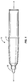
FIG. 1 is a longitudinal view of a micro motion poppet valve assembly constructed in accordance with the disclosure. -
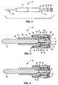
FIG. 2 is an exploded longitudinal view of the micro motion poppet valve assembly ofFIG. 1 . -
FIG. 3 is a longitudinal cross-sectional view of the micro motion poppet valve assembly ofFIG. 2 in a closed position. -
FIG. 4 is a longitudinal cross-sectional view of the micro motion poppet valve assembly ofFIG. 2 in an open position. -
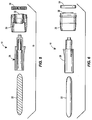
FIG. 5 is an exploded cross-sectional view of the micro motion poppet valve assembly ofFIG. 2 . -
FIG. 6 is an exploded longitudinal view of the micro motion poppet valve assembly ofFIG. 2 . -
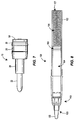
FIG. 7 is a longitudinal view of the micro motion poppet valve assembly ofFIG. 2 . -
FIG. 8 is a longitudinal view of a writing instrument including the micro motion poppet valve assembly ofFIG. 1 . - A micro motion poppet valve for a writing instrument provides delivery of ink with large pigment particles by a porous extruded plastic writing nib with minimal nib movement and relatively light actuation forces. The micro motion poppet valve includes a porous extruded plastic writing nib coupled to a valve stem, the valve stem being coupled to a valve plug. The valve stem is partially disposed within a valve body, the valve body being coupled to a biasing element, which biases the valve stem towards a closed position. When a user presses the nib against a writing surface, the valve plug moves away from the valve body to allow ink to flow from an ink reservoir to the nib.
- The disclosed micro motion poppet valve assembly and writing instrument are particularly useful in delivering ink having large pigment particles, such as brass pigments and correction fluids. By avoiding the use of capillary channels typically associated with the markers preferred by consumers, the disclosed micro motion poppet valve is able to maintain such large pigment particles in suspension and prevent agglomeration of the particles whereas such pigment particles often clog the capillary channels of conventional markers and thereby often cause conventional markers containing such inks to fail.
- A writing instrument incorporating the micro motion poppet valve assembly has ability to deliver ink compositions containing relatively large pigment particles, for example, pigment particles having a diameter greater than about 15 microns, greater than 20 microns, greater than 25 microns, greater than 30 microns, and/or greater than 40 microns without having to depress and continue to depress the nib with significant force when writing with the writing instrument. Moreover, the disclosed writing instrument need not include a capillary/fibrous ink reservoir or fibrous nib and can therefore be much less susceptible to clogging than other writing instruments including relatively large pigment particles. Furthermore, the disclosed writing instrument can utilize relatively high viscosity inks which can minimize pigment particle settling and obviate the need to mechanically agitate the system so as to uniformly distribute the pigment particles throughout the ink composition.
- The disclosed micro motion valve assembly may actuated by very small (approximately 0.01 inches or approximately .254 mm) axial movements of a writing nib and require very little pressure to activate the valve, which is desirable from a consumer perspective. In one embodiment a mass of between approximately 75 grams and approximately 150 grams (i.e., between one and two ounces) is sufficient to activate the valve from the closed position to the open position. Such small masses enable the valve to be actuated during the normal course of writing, rather than forcing a user to stop and purposefully actuate the valve, and continue to apply such pressure to continue to write, as in prior art valve actuated writing systems.
- Turning now to
Fig. 1 , a micromotion valve assembly 10 according to the invention generally includes abarrel portion 12. Thebarrel portion 12 may be connected to a shell of a writing instrument that contains an ink reservoir in fluid communication with the micromotion valve assembly 10. Anib 22 extends outward from one end of thebarrel portion 12. Thevalve assembly 10 selectively permits or restricts ink flow from the ink reservoir to thenib 22. When pressure is applied to thenib 22 by a user contacting thenib 22 with a substrate, thenib 22 is moved along a longitudinal axis A of thebarrel portion 12 towards the ink reservoir, and thevalve assembly 10 opens to permit ink to flow to thenib 22. -
Fig. 2 illustrates thenib 22 in an exploded view of thevalve assembly 10. Thenib 22 is housed in anib holder 24, which is formed at one end of avalve stem 28. Thenib 22 is mounted within an opening in afirst end 25 of thenib holder 24. Thevalve assembly 10 includes thebarrel portion 12, thevalve stem 28, avalve body 26, avalve biasing element 30, and avalve plug 58. When thenib 22 moves towards the biasing element 30 (and hence towards the ink reservoir), thevalve stem 28 also moves towards biasing element 30 (and hence towards the ink reservoir), opening thevalve assembly 10, allowing ink to flow from the ink reservoir to thenib 22. - Turning now to
FIG. 3 , thevalve body 26 includes acentral bore 34 having a generally funnel-shapedfirst portion 35 that is separated from a generally funnel-shapedsecond portion 37 by ashoulder 39. Thesecond portion 37 of thecentral bore 34 receives thebiasing element 30, which in the illustrated embodiment comprises a resilient spring. Thevalve body 26 includes aconical front portion 40 that seats within a front end of thebarrel portion 12. Thevalve body 26 may also include anannular recess 50 sized to receive aseal 52, such as an o-ring, to seal thevalve body 26 against an inner surface of thebarrel portion 12. In other embodiments, thevalve body 26 may be integrally formed with or even provided by thebarrel portion 12, or an instrument body or shell. - The
seal 52 may be formed integrally with the biasingelement 30 during a single shot in an injection molding process. Thevalve body 26 and the biasingelement 30 may be integrally formed during two separate shots of a two-shot injection molding process. More specifically, thevalve body 26 may be formed of a thermoplastic material during a first shot, while the biasingelement 30 and theseal 52 may be formed from a thermoplastic elastomer (TPE) during a second shot. As a result, thevalve body 26, the biasingelement 30, and theseal 52 can be integrally formed, while advantageously retaining two different sets of material properties for therespective components - Thermoplastic materials that may be used for the
valve body 26 include but are not limited to various thermoplastics such as polyethylene, HDPE, Nylon, polyvinylchloride (PVC), and blends thereof. Specific exemplary thermoplastic materials include but are not limited to Model No. P4C6Z-022 and Model No. P4C6B-024B, both made by Huntsman International (Woodlands, TX), Model No. HM35Z2 made by Arco Chemical Company (Newtown Square, PA), and Marlex HLN-350 made by Phillips Sumika Polypropylene Company (Woodlands, TX). - TPEs that may be used for the biasing
element 30 and theseal 52 should have a stiffness in the range of between approximately 20 durometer and approximately 80 durometer, preferably in the range of between approximately 30 durometer and approximately 65 durometer, and more preferably in the range of between approximately 35 durometer and approximately 45 durometer. Stiffnesses in these ranges provide adequate biasing force while preventing problems encountered with stiffer materials, such as compression set. Specific exemplary TPE's include but are not limited to Model No. LC290-105 made by GLS Corp. (McHenry, IL), Dynaflex G2780-0001 and Dynaflex G7980-1001-00, also made by GLS Corp., Santoprene 101-73, Santoprene 101-80, Santoprene 101-87, Santoprene 8201-70, Santoprene 8201-80, Santoprene 8201-90, and Santoprene 8211-75, made by Advanced Elastomer Systems, L.P. (Akron, OH), and Monprene MP-2890M, Monprene MP-2870, Monprene MP-1894, and Monprene MP-2780, made by Teknor Apex Company (Pawtucket, RI). - The biasing
element 30 includes a generallycylindrical body portion 36 and a cone-shapedportion 38. The cone-shapedportion 38 is generally disposed within thesecond portion 37 of thecentral bore 34 when the biasingelement 30 is inserted into thevalve body 26. The cone-shapedportion 38 is axially flexible longitudinally within thecentral bore 34, as will be discussed further hereinafter. At one end, opposite the cone-shapedportion 38, the biasing element has a raisedvalve seat 41. The raisedvalve seat 41 in this embodiment takes the form of a cantileveredledge 43. The cantileveredledge 43 is flexible and forms a liquid tight seal with thevalve plug 58 when thevalve assembly 10 is in a closed position. - As illustrated, the
valve stem 28 includes astem body 54 that is connected to thevalve plug 58 at one end with acylindrical connector 59 that fits within anopening 65 of thevalve plug 58. Thestem body 54 also includes one or moreangled ribs 67 distributed about a periphery of thestem body 54. Theangled ribs 67 extend outward from a periphery of thestem body 54 and axially along thestem body 54, terminating in aflat end 69. Theflat end 69 cooperates with theshoulder 39 in thevalve body 26 to limit axial movement (which would be otherwise introduced by application of normal forces used during writing) of thestem body 54 with respect to thevalve body 26. In other words, theflat end 69 and theshoulder 39 cooperate to form a stop that limits longitudinal movement of the valve stem body 54 (and thus the nib 22) in an aft direction, towards the ink reservoir. By carefully setting the distance between theflat end 69 and theshoulder 39, longitudinal travel of thenib 22 can be controlled and set to an amount that is barely (if at all) perceptible to a user when writing. In this way, a user will activate thevalve assembly 10 during the normal course of writing without disturbing the user's natural writing stroke. When thevalve assembly 10 is in a closed position, a particularly useful distance between theflat end 69 and theshoulder 39 may be in the range of approximately 0.0508cm (0.02 in) to approximately 0.0127cm (0.005 in), more preferably in the range of approximately 0.0381cm (0.015 in) to approximately 0.02032cm (0.008 in), and even more preferably in the range of approximately 0.03048cm (0.012 in) to approximately 0.02032 (0.008 in). These ranges provide adequate clearance for the large pigment particles to flow through while remaining nearly imperceptible to a user of the writing instrument. - In the closed position, a
first surface 71 of the valve plug 58 seats against the cantileveredledge 43 to restrict ink flow through thevalve assembly 10. Thevalve plug 58 may be generally cylindrical in shape including an outerannular flange 60 formed about a periphery of thevalve plug 58. The outerannular flange 60 cooperates with one end of thevalve body 26 to provide a secondary seal for an ink flow channel that is formed between thevalve plug 58 and thevalve body 26 and the cantileveredflange 43 upon application of normal pressure during writing. The ink flow channel continues between thevalve stem 28 and the biasingelement 30, through one or more openings orslots 68 located in thevalve stem body 54 and into alongitudinal bore 62 in thevalve stem body 54 that is open at afirst end 64 and closed at asecond end 66.Slots 68 may be preferred for their ability to pass relatively large pigment particles without becoming clogged. In other embodiments, other shapes or sizes of openings may be used that are appropriate to pass the pigment particles disposed in the ink being used by the writing instrument. Thelongitudinal bore 62 continues the ink flow path through thevalve stem body 54 to thenib 22. Ink flows into thelongitudinal bore 62 through the plurality of openings orslots 68, proximate the second,closed end 66 of thelongitudinal bore 62, when thevalve assembly 10 is open (seeFIG. 4 ). The valve stembody 54 also includes anannular channel 70 located between thefirst end 64 and thesecond end 66 of thestem body 54. Theannular channel 70 is located proximate theflat end 69 of theangled rib 67 in this embodiment. In other embodiments, theannular channel 70 may be located closer to thesecond end 66 of thestem body 54. Theannular channel 70 receives anopen end 72 of the cone-shapedportion 38 of the biasingelement 30, at least a portion of thevalve stem body 54 being located within the cone-shapedportion 38 of the biasingelement 30. -
Fig. 3 illustrates thevalve assembly 10 in a closed position, preventing ink flow from the ink reservoir to the writingnib 22. In the closed position, one side of the valve plug 58 contacts theseat 41 on the biasingelement 30. Thevalve plug 58 and theseat 41 form a seal that prevents ink from flowing into thelongitudinal bore 62. In the absence of writing pressure, the cone-shapedportion 38 of the biasingelement 30 biases thevalve stem 28 forward, towards a closed position. Thus, thevalve stem 28 and nib 18 are longitudinally movable within thebarrel portion 12, while thevalve body 26 and biasingelement 30 remain fixed with respect to thebarrel portion 12. - As discussed above, in the closed position, illustrated in
Fig. 3 , theflat end 69 ofangled rib 67 is spaced from theshoulder 39 by between approximately 0.127mm (0.005 inches) and approximately 0.508mm (0.02 inches), preferably between approximately 0.127mm (0.005 inches) and approximately 0.381 mm (0.015 inches), and more preferably between approximately 0.2032mm (0.008 inches) and approximately 0.3048mm (0.012 inches). This spacing imparts agap 90 of a similar size between thevalve plug 58 and the raisedvalve seat 41 when thevalve assembly 10 is actuated by a user to an open position, as illustrated inFIG. 4 . In particular, thegap 90 may be sized to between approximately 0.127mm (0.005 inches) and approximately 0.508mm (0.02 inches), preferably between approximately 0.127mm (0.005 inches) and approximately 0.381mm (0.015 inches), and more preferably between approximately 0.2032mm (0.008 inches) and approximately 0.3048mm (0.012 inches). -
Fig. 4 illustrates the valve assembly 16 in an open position. When thenib 22 is displaced aft, towards the biasing element 30 (and hence towards the ink reservoir), thenib 22 and thevalve stem 26 move aft until theflat end 69 of theangled rib 67 contacts theshoulder 39. As the nib 18 moves aft, thevalve stem 28 also moves aft, which causes thevalve plug 58 to disengage from thevalve seat 41. As thevalve plug 58 disengages from thevalve seat 41, ink begins to flow from the ink reservoir, through thegap 90 created between thevalve plug 58 and thevalve seat 41 and into thelongitudinal bore 62 through the openings/slots 68. Ink continues to flow under gravity or capillary action through thelongitudinal bore 62 and to thenib 22. -
FIGS. 5 and 6 illustrate the major components of thevalve assembly 10 in an assembly order. More particularly, thenib 22 may be inserted into thevalve stem 28. The valve stem 28 may be inserted into thecombination valve body 26/biasingelement 30. Finally, thevalve plug 58 may be attached to thevalve stem 28. By forming thevalve body 26 and the biasingelement 30 in a two-shot injection molding process, assembly time for thevalve assembly 10 is reduced and part inventory is decreased. -
FIG. 7 illustrates thevalve assembly 10 in a fully assembled condition. -
FIG. 8 illustrates one embodiment of awriting instrument 100 that includes a micro motionpoppet valve assembly 110, as described above. The writing instrument includes aninstrument body 102 and a micro motionpoppet valve assembly 110 disposed at afirst end 105 of theinstrument body 102. Anink reservoir 104 is disposed within the instrument body for supplying ink awriting nib 122. As illustrated, a pressurizingelement 106 is disposed between theink reservoir 104 and asecond end 107 of theinstrument body 102, but the pressurizingelement 106 is merely an optional component. - The pressurizing
element 106, which is illustrated as a spring, may be located within theinstrument body 102, opposite thenib 122 and between an end plug (not shown) of thewriting instrument 100 and theink reservoir 104. Thespring 106 applies pressure to theink reservoir 104 in order to pressurize ink within theink reservoir 104. Of course, a pressurized gas could be used as a pressurizingelement 106 instead of spring. Aplug 108 separates the pressurizingelement 106 from theink reservoir 104. Theplug 108 forms a seat that allows the pressurizingelement 106 to impart a pressurizing force to theink reservoir 104, thereby pressurizing ink within theink reservoir 104. - The
nib 122 is fluidly connected to theink reservoir 106 by an ink channel. The ink channel begins at theink reservoir 106, which is fluidly connected to the gap 90 (Fig. 4 ) formed between thevalve plug 58 and the raisedvalve seat 41 located on the biasingelement 30. The ink channel continues between an outer surface of thevalve stem body 54 and an inner surface of the biasing element 30 (Fig. 3 ). The ink channel transitions into thelongitudinal bore 62 through theopenings 68. The ink channel continues within thelongitudinal bore 62 until reaching thenib 22. The ink channel fluidly connects thenib 22, thelongitudinal bore 62, the inner surface of the biasingelement 30, thegap 90, and theink reservoir 106 to one another. - As discussed above, the ink used in the disclosed micro motion poppet valve assembly can include relatively large particle pigments. Some inks may also be shear-thinning, i.e., non-Newtonian liquids that exhibit shear-thinning flow behavior when subjected to shear. Some shear-thinning inks become thin, readily flowable liquids having a viscosity of no greater than about 1000 mPa·sec at shear rates greater than about 100 sec-1. Exemplary shear thinning inks may have a shear thinning index of between approximately 0.01 and approximately 0.8.
- To enhance the shear thinning characteristics of some inks, the pressurized ink reservoir provides shearing energy to the ink as the ink flows through the micro motion poppet valve. In one embodiment, the ink reservoir is pressurized to between approximately 6.89 kPa (1 pound per square inch (psi)) and approximately 137.9 kPa (20 psi), between approximately 13.79 kPa (2 psi) and approximately 68.95 kPa (10 psi), and/or between approximately (13.79 kPa) (2 psi) and approximately 34.47 kPa (5 psi).
- Although certain writing instruments and poppet valve assemblies have been described herein in accordance with the teachings of the present disclosure, the scope of coverage of this patent is not limited thereto. On the contrary, while the invention has been shown and described in connection with various preferred embodiments, it is apparent that certain changes and modifications, in addition to those mentioned above, may be made within the scope of the current invention as defined in the appended claims.
Claims (15)
- A micro motion poppet valve assembly for a writing instrument, the poppet valve assembly comprising:a writing nib (22);a valve body (26) coupled to a biasing element (30), the valve body (26) further comprising a shoulder (39) within a central bore (34) of the valve body,a valve stem (28) partially disposed within the valve body (26), anda valve plug (58) coupled to the valve stem (28), wherein the writing nib (22) is coupled to the valve stem (28), the writing nib (22) and the valve stem (28) being longitudinally movable with respect to the valve body (26) and the biasing element (30), andcharacterized in that the biasing element includes a body portion (36) and a cone-shaped portion (38), the cone-shaped portion (38) being deformable along a longitudinal axis and configured to enable the valve plug (28) to move in a first direction to an open position to open an ink channel between the writing nib (22) and an ink reservoir (104) in use, and the cone-shaped portion (38) biasing the valve stem in a second direction to a closed position; andthe valve stem (28) further comprising an angled rib (67) disposed on a periphery of the valve stem (28), wherein the angled rib (67) is configured to cooperate with the shoulder (39) in the valve body (26) to limit axial movement of the nib (22) with respect to the valve body (26) in the first direction.
- The micro motion poppet valve assembly of claim 1, wherein the valve stem (28) further comprises a longitudinal bore (62)and a plurality of openings (68) in the stem, the plurality of openings (68) providing fluid communication between the longitudinal bore and the ink reservoir (104).
- The micro motion poppet valve assembly of any one of the preceding claims, wherein the valve stem (28) includes an annular channel disposed in an outer surface thereof; and preferably wherein an open end of the cone-shaped portion (38) is received in the annular channel.
- The micro motion poppet valve assembly of any one of the preceding claims, wherein the biasing element (30) biases the valve stem (28) towards the nib (22)
- The micro motion poppet valve assembly of any one of the preceding claims, wherein the valve body includes a central bore, the cone-shaped portion (38) of the biasing element (30) being disposed in the central bore (34).
- The micro motion poppet valve assembly of any one of the preceding claims, wherein the valve body (26) and the biasing element (30) are integral with one another and formed in a two-shot injection molding process.
- The micro motion poppet valve assembly of any one of the preceding claims, wherein the valve body is formed from a thermoplastic material during a first shot and the biasing element is formed from a TPE material during a second shot.
- The micro motion poppet valve assembly of any one of the preceding claims, wherein the valve plug (58) includes an annular flange that seats against the valve body.
- The micro motion poppet valve assembly of any one of the preceding claims, wherein the biasing element (30) includes a raised valve seat (41) that cooperates with the valve plug (58) to selectively permit or restrict ink flow through the valve assembly, and preferably wherein the raised valve seat (41) includes a cantilever ledge (43).
- The micro motion poppet valve assembly of any one of the preceding claims, wherein the valve body (26) includes a cone-shaped front portion.
- The micro motion poppet valve assembly of any one of the preceding claims, wherein the valve body (26) includes an annular channel (50) on an outer surface thereof that is sized to receive an annular seal, and preferably further comprising an annular seal (52) disposed in the annular channel, and preferably wherein the annular seal (52) is integrally formed with the biasing element (30) during a second shot of a two-shot injection molding process.
- The micro-motion poppet valve assembly of any preceding claim, wherein the angled rib (67) includes a flat end (69), and preferably wherein the flat end (69) is separated from the shoulder (39) by a distance of between approximately 0.508mm (0.02 in) and approximately 0.127mm (0.005 in).
- The micro-motion poppet valve assembly of any of the preceding claims wherein the nib (22) is a porous plastic nib.
- A writing instrument (100) for use with inks comprising large pigment particles, the writing instrument comprising:an instrument body (102);an ink reservoir (104) disposed within the instrument body (102);a valve assembly (110) disposed within the instrument body, the valve assembly including a writing nib (122); a valve body (26) coupled to a biasing element (30), the valve body (26) further comprising a shoulder (39) within a central bore (34) of the valve body, a valve stem (28) partially disposed within the valve body (26), and a valve plug (58) coupled to the valve stem,wherein the writing nib (122) is coupled to the valve stem (28), the writing nib (122) and valve stem (28) being longitudinally movable with respect to the valve body (26) and biasing element (30), andwherein an ink channel fluidly connects the ink reservoir (104), the valve plug (58), the biasing element (30), the valve stem (28), and the writing nib (122) for delivery of ink from the ink reservoir (104) to the writing nib (122);characterized in that the biasing element (30) includes a body portion (36) and a cone-shaped portion (38), the cone-shaped portion (38) being deformable along a longitudinal axis and configured to enable the valve plug (28) to move in a first direction to an open position to open the ink channel between the writing nib (22) and the ink reservoir (104) in use, and the cone-shaped portion (38) biasing the valve stem in a second direction to a closed position, andthe valve stem (28) further comprising an angled rib (67) disposed on a periphery of the valve stem (28), wherein the angled rib (67) is configured to cooperate with the shoulder (39) in the valve body (26) to limit axial movement of the nib (22) with respect to the valve body (26) in the first direction.
- The writing instrument of claim 14, further comprising a pressurizing element (106) disposed in the instrument body, the pressurizing element (106) imparting a pressurizing force to the ink reservoir.
Applications Claiming Priority (2)
| Application Number | Priority Date | Filing Date | Title |
|---|---|---|---|
| US13/341,211 US9050850B2 (en) | 2011-12-30 | 2011-12-30 | Micro motion poppet valve assembly for delivery of ink with large pigment particles to a writing nib and writing instrument comprising same |
| PCT/US2012/070965 WO2013101664A1 (en) | 2011-12-30 | 2012-12-20 | Micro motion poppet valve assembly for delivery of ink with large pigment particles to a writing nib and writing instrument comprising same |
Publications (2)
| Publication Number | Publication Date |
|---|---|
| EP2768679A1 EP2768679A1 (en) | 2014-08-27 |
| EP2768679B1 true EP2768679B1 (en) | 2016-05-04 |
Family
ID=47595002
Family Applications (1)
| Application Number | Title | Priority Date | Filing Date |
|---|---|---|---|
| EP12816570.1A Not-in-force EP2768679B1 (en) | 2011-12-30 | 2012-12-20 | Micro motion poppet valve assembly for delivery of ink with large pigment particles to a writing nib and writing instrument comprising same |
Country Status (7)
| Country | Link |
|---|---|
| US (1) | US9050850B2 (en) |
| EP (1) | EP2768679B1 (en) |
| JP (1) | JP2015507564A (en) |
| CN (1) | CN104010827A (en) |
| AU (1) | AU2012362697B2 (en) |
| MX (1) | MX2014008005A (en) |
| WO (1) | WO2013101664A1 (en) |
Families Citing this family (11)
| Publication number | Priority date | Publication date | Assignee | Title |
|---|---|---|---|---|
| WO2012118757A1 (en) * | 2011-03-01 | 2012-09-07 | Exxonmobil Upstream Research Company | Apparatus and systems having a reciprocating valve head assembly and swing adsorption processes related thereto |
| USD754721S1 (en) * | 2013-12-20 | 2016-04-26 | Sanford, L.P. | Display screen or portion thereof with icons |
| JP6630473B2 (en) * | 2014-10-16 | 2020-01-15 | 株式会社呉竹 | Pens and pen refills |
| CA2962886A1 (en) * | 2016-03-31 | 2017-09-30 | Sanford, L.P. | Ink delivery system |
| US11124644B2 (en) * | 2016-09-01 | 2021-09-21 | University Of Florida Research Foundation, Inc. | Organic microgel system for 3D printing of silicone structures |
| EP3378348B1 (en) * | 2017-03-20 | 2020-07-08 | Aptar Radolfzell GmbH | Fluid dispenser with dispensing sponge |
| US11040566B2 (en) * | 2018-08-21 | 2021-06-22 | Lb Usa Flexibles, Inc. | Pen dispenser with plastic spring actuator |
| JP1659747S (en) * | 2019-08-22 | 2020-05-18 | ||
| JP1659749S (en) * | 2019-08-22 | 2020-05-18 | ||
| CN111846596B (en) * | 2020-08-05 | 2025-07-11 | 圣戈班汇杰(杭州)新材料有限公司 | Convenient liquid primer package |
| EP4011638A1 (en) * | 2020-12-11 | 2022-06-15 | Société BIC | A writing instrument comprising a switchable flow material |
Family Cites Families (17)
| Publication number | Priority date | Publication date | Assignee | Title |
|---|---|---|---|---|
| US2320823A (en) * | 1942-03-25 | 1943-06-01 | Mono Script Co Inc | Fountain marking device |
| US2996750A (en) * | 1959-04-06 | 1961-08-22 | Cholet Bertram | Fountain pen |
| US4195941A (en) * | 1977-02-25 | 1980-04-01 | Mark-Tex Corporation | Marking pen writing tip |
| JPS6112135Y2 (en) * | 1981-05-06 | 1986-04-16 | ||
| JPS5817187U (en) * | 1981-07-24 | 1983-02-02 | 三菱鉛筆株式会社 | writing implements |
| JPS5889388U (en) * | 1981-12-14 | 1983-06-17 | 株式会社 トンボ鉛筆 | Notsuku type fiber pen |
| JPH0312362Y2 (en) * | 1985-03-29 | 1991-03-25 | ||
| JPH062782Y2 (en) * | 1986-06-28 | 1994-01-26 | ぺんてる株式会社 | Applicator with valve |
| JPS63141779U (en) * | 1987-03-10 | 1988-09-19 | ||
| US5676481A (en) * | 1991-09-26 | 1997-10-14 | Gillette Company | Marking instruments |
| JP2003154785A (en) | 2001-11-26 | 2003-05-27 | Kotobuki:Kk | Direct liquid writing instrument |
| JP4298968B2 (en) | 2002-06-19 | 2009-07-22 | 株式会社呉竹 | Writing instrument |
| EP1656261B1 (en) * | 2003-08-18 | 2010-10-06 | Sanford, L.P. | Multiple width marking instrument |
| US7704003B2 (en) | 2005-10-07 | 2010-04-27 | U-Mark, Inc. | Liquid applicator |
| WO2009054915A2 (en) | 2007-10-19 | 2009-04-30 | Flocon, Inc. | Liquid applicator |
| US8393814B2 (en) * | 2009-01-30 | 2013-03-12 | Sanford, L.P. | Retractable instrument having a two stage protraction/retraction sequence |
| US8753027B2 (en) * | 2009-07-14 | 2014-06-17 | Flocon, Inc. | Liquid applicator device |
-
2011
- 2011-12-30 US US13/341,211 patent/US9050850B2/en not_active Expired - Fee Related
-
2012
- 2012-12-20 WO PCT/US2012/070965 patent/WO2013101664A1/en not_active Ceased
- 2012-12-20 CN CN201280064981.5A patent/CN104010827A/en active Pending
- 2012-12-20 JP JP2014550378A patent/JP2015507564A/en active Pending
- 2012-12-20 EP EP12816570.1A patent/EP2768679B1/en not_active Not-in-force
- 2012-12-20 AU AU2012362697A patent/AU2012362697B2/en not_active Ceased
- 2012-12-20 MX MX2014008005A patent/MX2014008005A/en unknown
Non-Patent Citations (1)
| Title |
|---|
| None * |
Also Published As
| Publication number | Publication date |
|---|---|
| CN104010827A (en) | 2014-08-27 |
| AU2012362697B2 (en) | 2015-07-16 |
| JP2015507564A (en) | 2015-03-12 |
| AU2012362697A1 (en) | 2014-05-29 |
| US20130170887A1 (en) | 2013-07-04 |
| EP2768679A1 (en) | 2014-08-27 |
| US9050850B2 (en) | 2015-06-09 |
| WO2013101664A1 (en) | 2013-07-04 |
| MX2014008005A (en) | 2014-08-21 |
Similar Documents
| Publication | Publication Date | Title |
|---|---|---|
| US9050850B2 (en) | Micro motion poppet valve assembly for delivery of ink with large pigment particles to a writing nib and writing instrument comprising same | |
| US4960340A (en) | Implement for applying liquid | |
| JP6105563B2 (en) | Fluid discharge head | |
| US20150298489A1 (en) | Writing instrument | |
| CN109937146B (en) | Retractable Liquid Applicator Unit | |
| CA2400156C (en) | Hand-held dispenser for applying a flowable correction medium on a substrate surface | |
| CN107264123B (en) | Writing implement | |
| EP4037916B1 (en) | Coupling device | |
| US7922412B2 (en) | Fluid feeder of applicator | |
| US6435751B1 (en) | Click type writing implement | |
| US5454658A (en) | Rear end knocking type liquid discharge apparatus | |
| EP1896267A2 (en) | Writing implement for painting, drawing and marking | |
| JP7430454B2 (en) | liquid dispensing tool | |
| JP2025150371A (en) | writing implements | |
| JP4419318B2 (en) | Applicator with valve | |
| JP2025103969A (en) | Ink container and writing implement equipped with ink container | |
| CN119451755A (en) | Spray gun system with flexible flow control valve | |
| JP2005225086A (en) | Liquid applicator | |
| JP2005343097A (en) | Liquid applicator | |
| JP2005059369A (en) | Fluid applicator | |
| JP2006187892A (en) | Liquid applicator | |
| JP2005059365A (en) | Fluid applicator | |
| JP2005169854A (en) | Pressurized ballpoint pen | |
| JP2005225066A (en) | Liquid applicator | |
| JP2005059366A (en) | Fluid applicator |
Legal Events
| Date | Code | Title | Description |
|---|---|---|---|
| PUAI | Public reference made under article 153(3) epc to a published international application that has entered the european phase |
Free format text: ORIGINAL CODE: 0009012 |
|
| 17P | Request for examination filed |
Effective date: 20140521 |
|
| AK | Designated contracting states |
Kind code of ref document: A1 Designated state(s): AL AT BE BG CH CY CZ DE DK EE ES FI FR GB GR HR HU IE IS IT LI LT LU LV MC MK MT NL NO PL PT RO RS SE SI SK SM TR |
|
| DAX | Request for extension of the european patent (deleted) | ||
| REG | Reference to a national code |
Ref country code: DE Ref legal event code: R079 Ref document number: 602012018183 Country of ref document: DE Free format text: PREVIOUS MAIN CLASS: B43K0001080000 Ipc: B43K0005180000 |
|
| GRAP | Despatch of communication of intention to grant a patent |
Free format text: ORIGINAL CODE: EPIDOSNIGR1 |
|
| RIC1 | Information provided on ipc code assigned before grant |
Ipc: B43K 1/08 20060101ALI20150723BHEP Ipc: B43K 8/12 20060101ALI20150723BHEP Ipc: B43K 5/18 20060101AFI20150723BHEP |
|
| INTG | Intention to grant announced |
Effective date: 20150813 |
|
| GRAS | Grant fee paid |
Free format text: ORIGINAL CODE: EPIDOSNIGR3 |
|
| GRAR | Information related to intention to grant a patent recorded |
Free format text: ORIGINAL CODE: EPIDOSNIGR71 |
|
| GRAA | (expected) grant |
Free format text: ORIGINAL CODE: 0009210 |
|
| INTG | Intention to grant announced |
Effective date: 20160310 |
|
| AK | Designated contracting states |
Kind code of ref document: B1 Designated state(s): AL AT BE BG CH CY CZ DE DK EE ES FI FR GB GR HR HU IE IS IT LI LT LU LV MC MK MT NL NO PL PT RO RS SE SI SK SM TR |
|
| REG | Reference to a national code |
Ref country code: GB Ref legal event code: FG4D |
|
| REG | Reference to a national code |
Ref country code: CH Ref legal event code: EP |
|
| REG | Reference to a national code |
Ref country code: AT Ref legal event code: REF Ref document number: 796566 Country of ref document: AT Kind code of ref document: T Effective date: 20160515 |
|
| REG | Reference to a national code |
Ref country code: IE Ref legal event code: FG4D |
|
| REG | Reference to a national code |
Ref country code: DE Ref legal event code: R096 Ref document number: 602012018183 Country of ref document: DE |
|
| REG | Reference to a national code |
Ref country code: NL Ref legal event code: MP Effective date: 20160504 |
|
| REG | Reference to a national code |
Ref country code: LT Ref legal event code: MG4D |
|
| PG25 | Lapsed in a contracting state [announced via postgrant information from national office to epo] |
Ref country code: FI Free format text: LAPSE BECAUSE OF FAILURE TO SUBMIT A TRANSLATION OF THE DESCRIPTION OR TO PAY THE FEE WITHIN THE PRESCRIBED TIME-LIMIT Effective date: 20160504 Ref country code: LT Free format text: LAPSE BECAUSE OF FAILURE TO SUBMIT A TRANSLATION OF THE DESCRIPTION OR TO PAY THE FEE WITHIN THE PRESCRIBED TIME-LIMIT Effective date: 20160504 Ref country code: NL Free format text: LAPSE BECAUSE OF FAILURE TO SUBMIT A TRANSLATION OF THE DESCRIPTION OR TO PAY THE FEE WITHIN THE PRESCRIBED TIME-LIMIT Effective date: 20160504 Ref country code: NO Free format text: LAPSE BECAUSE OF FAILURE TO SUBMIT A TRANSLATION OF THE DESCRIPTION OR TO PAY THE FEE WITHIN THE PRESCRIBED TIME-LIMIT Effective date: 20160804 |
|
| REG | Reference to a national code |
Ref country code: AT Ref legal event code: MK05 Ref document number: 796566 Country of ref document: AT Kind code of ref document: T Effective date: 20160504 |
|
| PG25 | Lapsed in a contracting state [announced via postgrant information from national office to epo] |
Ref country code: GR Free format text: LAPSE BECAUSE OF FAILURE TO SUBMIT A TRANSLATION OF THE DESCRIPTION OR TO PAY THE FEE WITHIN THE PRESCRIBED TIME-LIMIT Effective date: 20160805 Ref country code: RS Free format text: LAPSE BECAUSE OF FAILURE TO SUBMIT A TRANSLATION OF THE DESCRIPTION OR TO PAY THE FEE WITHIN THE PRESCRIBED TIME-LIMIT Effective date: 20160504 Ref country code: PT Free format text: LAPSE BECAUSE OF FAILURE TO SUBMIT A TRANSLATION OF THE DESCRIPTION OR TO PAY THE FEE WITHIN THE PRESCRIBED TIME-LIMIT Effective date: 20160905 Ref country code: SE Free format text: LAPSE BECAUSE OF FAILURE TO SUBMIT A TRANSLATION OF THE DESCRIPTION OR TO PAY THE FEE WITHIN THE PRESCRIBED TIME-LIMIT Effective date: 20160504 Ref country code: HR Free format text: LAPSE BECAUSE OF FAILURE TO SUBMIT A TRANSLATION OF THE DESCRIPTION OR TO PAY THE FEE WITHIN THE PRESCRIBED TIME-LIMIT Effective date: 20160504 Ref country code: LV Free format text: LAPSE BECAUSE OF FAILURE TO SUBMIT A TRANSLATION OF THE DESCRIPTION OR TO PAY THE FEE WITHIN THE PRESCRIBED TIME-LIMIT Effective date: 20160504 Ref country code: ES Free format text: LAPSE BECAUSE OF FAILURE TO SUBMIT A TRANSLATION OF THE DESCRIPTION OR TO PAY THE FEE WITHIN THE PRESCRIBED TIME-LIMIT Effective date: 20160504 |
|
| PG25 | Lapsed in a contracting state [announced via postgrant information from national office to epo] |
Ref country code: IT Free format text: LAPSE BECAUSE OF FAILURE TO SUBMIT A TRANSLATION OF THE DESCRIPTION OR TO PAY THE FEE WITHIN THE PRESCRIBED TIME-LIMIT Effective date: 20160504 |
|
| PG25 | Lapsed in a contracting state [announced via postgrant information from national office to epo] |
Ref country code: SK Free format text: LAPSE BECAUSE OF FAILURE TO SUBMIT A TRANSLATION OF THE DESCRIPTION OR TO PAY THE FEE WITHIN THE PRESCRIBED TIME-LIMIT Effective date: 20160504 Ref country code: RO Free format text: LAPSE BECAUSE OF FAILURE TO SUBMIT A TRANSLATION OF THE DESCRIPTION OR TO PAY THE FEE WITHIN THE PRESCRIBED TIME-LIMIT Effective date: 20160504 Ref country code: CZ Free format text: LAPSE BECAUSE OF FAILURE TO SUBMIT A TRANSLATION OF THE DESCRIPTION OR TO PAY THE FEE WITHIN THE PRESCRIBED TIME-LIMIT Effective date: 20160504 Ref country code: EE Free format text: LAPSE BECAUSE OF FAILURE TO SUBMIT A TRANSLATION OF THE DESCRIPTION OR TO PAY THE FEE WITHIN THE PRESCRIBED TIME-LIMIT Effective date: 20160504 Ref country code: DK Free format text: LAPSE BECAUSE OF FAILURE TO SUBMIT A TRANSLATION OF THE DESCRIPTION OR TO PAY THE FEE WITHIN THE PRESCRIBED TIME-LIMIT Effective date: 20160504 |
|
| REG | Reference to a national code |
Ref country code: DE Ref legal event code: R097 Ref document number: 602012018183 Country of ref document: DE |
|
| PG25 | Lapsed in a contracting state [announced via postgrant information from national office to epo] |
Ref country code: BE Free format text: LAPSE BECAUSE OF FAILURE TO SUBMIT A TRANSLATION OF THE DESCRIPTION OR TO PAY THE FEE WITHIN THE PRESCRIBED TIME-LIMIT Effective date: 20160504 Ref country code: PL Free format text: LAPSE BECAUSE OF FAILURE TO SUBMIT A TRANSLATION OF THE DESCRIPTION OR TO PAY THE FEE WITHIN THE PRESCRIBED TIME-LIMIT Effective date: 20160504 Ref country code: AT Free format text: LAPSE BECAUSE OF FAILURE TO SUBMIT A TRANSLATION OF THE DESCRIPTION OR TO PAY THE FEE WITHIN THE PRESCRIBED TIME-LIMIT Effective date: 20160504 Ref country code: SM Free format text: LAPSE BECAUSE OF FAILURE TO SUBMIT A TRANSLATION OF THE DESCRIPTION OR TO PAY THE FEE WITHIN THE PRESCRIBED TIME-LIMIT Effective date: 20160504 |
|
| PLBE | No opposition filed within time limit |
Free format text: ORIGINAL CODE: 0009261 |
|
| STAA | Information on the status of an ep patent application or granted ep patent |
Free format text: STATUS: NO OPPOSITION FILED WITHIN TIME LIMIT |
|
| 26N | No opposition filed |
Effective date: 20170207 |
|
| PG25 | Lapsed in a contracting state [announced via postgrant information from national office to epo] |
Ref country code: SI Free format text: LAPSE BECAUSE OF FAILURE TO SUBMIT A TRANSLATION OF THE DESCRIPTION OR TO PAY THE FEE WITHIN THE PRESCRIBED TIME-LIMIT Effective date: 20160504 |
|
| REG | Reference to a national code |
Ref country code: DE Ref legal event code: R119 Ref document number: 602012018183 Country of ref document: DE |
|
| PG25 | Lapsed in a contracting state [announced via postgrant information from national office to epo] |
Ref country code: MC Free format text: LAPSE BECAUSE OF FAILURE TO SUBMIT A TRANSLATION OF THE DESCRIPTION OR TO PAY THE FEE WITHIN THE PRESCRIBED TIME-LIMIT Effective date: 20160504 |
|
| REG | Reference to a national code |
Ref country code: CH Ref legal event code: PL |
|
| GBPC | Gb: european patent ceased through non-payment of renewal fee |
Effective date: 20161220 |
|
| REG | Reference to a national code |
Ref country code: FR Ref legal event code: ST Effective date: 20170831 |
|
| REG | Reference to a national code |
Ref country code: IE Ref legal event code: MM4A |
|
| PG25 | Lapsed in a contracting state [announced via postgrant information from national office to epo] |
Ref country code: LI Free format text: LAPSE BECAUSE OF NON-PAYMENT OF DUE FEES Effective date: 20161231 Ref country code: CH Free format text: LAPSE BECAUSE OF NON-PAYMENT OF DUE FEES Effective date: 20161231 Ref country code: FR Free format text: LAPSE BECAUSE OF NON-PAYMENT OF DUE FEES Effective date: 20170102 Ref country code: LU Free format text: LAPSE BECAUSE OF NON-PAYMENT OF DUE FEES Effective date: 20161220 |
|
| PG25 | Lapsed in a contracting state [announced via postgrant information from national office to epo] |
Ref country code: GB Free format text: LAPSE BECAUSE OF NON-PAYMENT OF DUE FEES Effective date: 20161220 Ref country code: DE Free format text: LAPSE BECAUSE OF NON-PAYMENT OF DUE FEES Effective date: 20170701 Ref country code: IE Free format text: LAPSE BECAUSE OF NON-PAYMENT OF DUE FEES Effective date: 20161220 |
|
| PG25 | Lapsed in a contracting state [announced via postgrant information from national office to epo] |
Ref country code: HU Free format text: LAPSE BECAUSE OF FAILURE TO SUBMIT A TRANSLATION OF THE DESCRIPTION OR TO PAY THE FEE WITHIN THE PRESCRIBED TIME-LIMIT; INVALID AB INITIO Effective date: 20121220 |
|
| PG25 | Lapsed in a contracting state [announced via postgrant information from national office to epo] |
Ref country code: IS Free format text: LAPSE BECAUSE OF FAILURE TO SUBMIT A TRANSLATION OF THE DESCRIPTION OR TO PAY THE FEE WITHIN THE PRESCRIBED TIME-LIMIT Effective date: 20160504 Ref country code: CY Free format text: LAPSE BECAUSE OF FAILURE TO SUBMIT A TRANSLATION OF THE DESCRIPTION OR TO PAY THE FEE WITHIN THE PRESCRIBED TIME-LIMIT Effective date: 20160504 Ref country code: MK Free format text: LAPSE BECAUSE OF FAILURE TO SUBMIT A TRANSLATION OF THE DESCRIPTION OR TO PAY THE FEE WITHIN THE PRESCRIBED TIME-LIMIT Effective date: 20160504 |
|
| PG25 | Lapsed in a contracting state [announced via postgrant information from national office to epo] |
Ref country code: BG Free format text: LAPSE BECAUSE OF FAILURE TO SUBMIT A TRANSLATION OF THE DESCRIPTION OR TO PAY THE FEE WITHIN THE PRESCRIBED TIME-LIMIT Effective date: 20160504 |
|
| PG25 | Lapsed in a contracting state [announced via postgrant information from national office to epo] |
Ref country code: MT Free format text: LAPSE BECAUSE OF NON-PAYMENT OF DUE FEES Effective date: 20161220 |
|
| PG25 | Lapsed in a contracting state [announced via postgrant information from national office to epo] |
Ref country code: AL Free format text: LAPSE BECAUSE OF FAILURE TO SUBMIT A TRANSLATION OF THE DESCRIPTION OR TO PAY THE FEE WITHIN THE PRESCRIBED TIME-LIMIT Effective date: 20160504 Ref country code: TR Free format text: LAPSE BECAUSE OF FAILURE TO SUBMIT A TRANSLATION OF THE DESCRIPTION OR TO PAY THE FEE WITHIN THE PRESCRIBED TIME-LIMIT Effective date: 20160504 |