EP2768552B1 - Device for applying medical fluid to and cutting within an area - Google Patents
Device for applying medical fluid to and cutting within an area Download PDFInfo
- Publication number
- EP2768552B1 EP2768552B1 EP12841119.6A EP12841119A EP2768552B1 EP 2768552 B1 EP2768552 B1 EP 2768552B1 EP 12841119 A EP12841119 A EP 12841119A EP 2768552 B1 EP2768552 B1 EP 2768552B1
- Authority
- EP
- European Patent Office
- Prior art keywords
- blade
- inlet port
- fluid
- flow channel
- fluid flow
- Prior art date
- Legal status (The legal status is an assumption and is not a legal conclusion. Google has not performed a legal analysis and makes no representation as to the accuracy of the status listed.)
- Not-in-force
Links
Images


Classifications
-
- A—HUMAN NECESSITIES
- A61—MEDICAL OR VETERINARY SCIENCE; HYGIENE
- A61B—DIAGNOSIS; SURGERY; IDENTIFICATION
- A61B17/00—Surgical instruments, devices or methods
- A61B17/32—Surgical cutting instruments
- A61B17/3209—Incision instruments
-
- A—HUMAN NECESSITIES
- A61—MEDICAL OR VETERINARY SCIENCE; HYGIENE
- A61B—DIAGNOSIS; SURGERY; IDENTIFICATION
- A61B17/00—Surgical instruments, devices or methods
- A61B17/32—Surgical cutting instruments
- A61B17/3209—Incision instruments
- A61B17/3211—Surgical scalpels, knives; Accessories therefor
-
- A—HUMAN NECESSITIES
- A61—MEDICAL OR VETERINARY SCIENCE; HYGIENE
- A61B—DIAGNOSIS; SURGERY; IDENTIFICATION
- A61B90/00—Instruments, implements or accessories specially adapted for surgery or diagnosis and not covered by any of the groups A61B1/00 - A61B50/00, e.g. for luxation treatment or for protecting wound edges
- A61B90/80—Implements for cleaning or washing the skin of surgeons or patients
-
- A—HUMAN NECESSITIES
- A61—MEDICAL OR VETERINARY SCIENCE; HYGIENE
- A61B—DIAGNOSIS; SURGERY; IDENTIFICATION
- A61B2217/00—General characteristics of surgical instruments
- A61B2217/002—Auxiliary appliance
- A61B2217/007—Auxiliary appliance with irrigation system
-
- A—HUMAN NECESSITIES
- A61—MEDICAL OR VETERINARY SCIENCE; HYGIENE
- A61M—DEVICES FOR INTRODUCING MEDIA INTO, OR ONTO, THE BODY; DEVICES FOR TRANSDUCING BODY MEDIA OR FOR TAKING MEDIA FROM THE BODY; DEVICES FOR PRODUCING OR ENDING SLEEP OR STUPOR
- A61M5/00—Devices for bringing media into the body in a subcutaneous, intra-vascular or intramuscular way; Accessories therefor, e.g. filling or cleaning devices, arm-rests
- A61M5/14—Infusion devices, e.g. infusing by gravity; Blood infusion; Accessories therefor
- A61M5/158—Needles for infusions; Accessories therefor, e.g. for inserting infusion needles, or for holding them on the body
- A61M2005/1585—Needle inserters
-
- A—HUMAN NECESSITIES
- A61—MEDICAL OR VETERINARY SCIENCE; HYGIENE
- A61M—DEVICES FOR INTRODUCING MEDIA INTO, OR ONTO, THE BODY; DEVICES FOR TRANSDUCING BODY MEDIA OR FOR TAKING MEDIA FROM THE BODY; DEVICES FOR PRODUCING OR ENDING SLEEP OR STUPOR
- A61M39/00—Tubes, tube connectors, tube couplings, valves, access sites or the like, specially adapted for medical use
- A61M39/02—Access sites
- A61M39/0208—Subcutaneous access sites for injecting or removing fluids
- A61M2039/0232—Subcutaneous access sites for injecting or removing fluids having means for facilitating the insertion into the body
-
- A—HUMAN NECESSITIES
- A61—MEDICAL OR VETERINARY SCIENCE; HYGIENE
- A61M—DEVICES FOR INTRODUCING MEDIA INTO, OR ONTO, THE BODY; DEVICES FOR TRANSDUCING BODY MEDIA OR FOR TAKING MEDIA FROM THE BODY; DEVICES FOR PRODUCING OR ENDING SLEEP OR STUPOR
- A61M35/00—Devices for applying media, e.g. remedies, on the human body
- A61M35/003—Portable hand-held applicators having means for dispensing or spreading integral media
-
- Y—GENERAL TAGGING OF NEW TECHNOLOGICAL DEVELOPMENTS; GENERAL TAGGING OF CROSS-SECTIONAL TECHNOLOGIES SPANNING OVER SEVERAL SECTIONS OF THE IPC; TECHNICAL SUBJECTS COVERED BY FORMER USPC CROSS-REFERENCE ART COLLECTIONS [XRACs] AND DIGESTS
- Y10—TECHNICAL SUBJECTS COVERED BY FORMER USPC
- Y10T—TECHNICAL SUBJECTS COVERED BY FORMER US CLASSIFICATION
- Y10T29/00—Metal working
- Y10T29/49—Method of mechanical manufacture
- Y10T29/49826—Assembling or joining
Definitions
- the present technology relates generally to medical devices for cutting a patient. More particularly, the present technology relates to applying medical fluid to an area and cutting within the area.
- cutting devices have been used, for example, to make incisions in patients.
- cutting devices include, but are not limited to, razor blades and scalpels.
- EP 0 456 470 A1 discloses a device for applying medical fluid to an area and for cutting within the area.
- a device is provided that can be used for both applying the fluid and cutting, as will become more evident. According to one embodiment, a device is provided that can be used to improve the health of the patient.
- the fluid is intended for medical use.
- the fluid is sterile.
- Figure 1A depicts a device 100 for applying fluid and cutting a patient from an angled view, according to one embodiment.
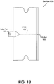
- Figure 1B depicts a top down view of the device 100, according to one embodiment.
- the device 100 includes an inlet port 108, a fluid flow channel (FFC) 106, an outlet 103, and a blade 101.
- FFC fluid flow channel
- the device 100 includes a blade 101 for cutting the patient.
- Figures 1A , 1B depict a blade 101 with a straight cutting edge.
- embodiments are well suited for other blade configurations.
- the blade 101 may be curved.
- the blade 101 may be made out of various types of materials, such as different types of metal.
- the blade 101 is similar to a razor blade.
- embodiments are well suited for blade configurations that are similar to other types of cutting devices, such as a scalpel or an exacto knife, among other things.
- the device 100 does not include a separate handle. However, embodiments are well suited to a device 100 that includes a handle.
- the inlet port 108 is configured for receiving the fluid into the device 100.
- the inlet port 108 can be configured to receive fluid from a reservoir of fluid.
- reservoirs include, but are not limited to, a syringe or a bottle.
- An outlet port of the reservoir may be inserted into the device 100's inlet port 108.
- the inlet port 108 may be designed to function with a particular type of reservoir.
- the size and shape of the inlet port may be compatible with a reservoir's outlet port.
- the inlet port 108 may have threads that, that for example, mate with threads associated with the reservoir's outlet. However, the inlet port 108 may not have threads.
- the inlet port 108 may be a universal port that is designed to function with a wide variety of reservoirs.
- the size and shape of the inlet port 108 may be designed to be large enough to accommodate a wide variety of reservoirs.
- the device 100's inlet port 108 may have material that expands when a reservoir's outlet port is inserted into the device 100's inlet port 108 and contracts, for example, when the reservoir's outlet port is extracted from the device 100's inlet port 108.
- the inlet port 108 is oriented in the center of the non-cutting edge 107 that is opposite the cutting edge 102.
- embodiments are well suited for other orientations of the inlet port 108.
- the inlet port 108 may be positioned on any non-cutting edge 107, 104, 105 of the device 100. More specifically, the inlet port 108 may be positioned on a side 104, 105 of the device 100, a side 104, 105 of a blade 101, on a handle of the device, on a spine of the device, among other things.
- the inlet port 108 may be oriented at any position along an edge 104, 105, 107, a handle or a spine.
- the inlet port 108 may be located in the center of an edge 104, 105, 107, off of the center of the edge 104, 105, 107, on a tip of a device, or a handle, among other things.
- the fluid flow channel 106 includes a first end 121 that is connected to the inlet port 108.
- the device 100 also includes a fluid flow channel 106 configured for the fluid to flow through the device 100.
- the fluid flow channel 106 is a narrow channel.
- the device 100 includes a single FFC 106.
- embodiments are well suited for a plurality of FFCs, for example, to more evenly distribute the fluid, as will become more evident.
- the FFC 106 is straight and is located down the center of the blade 101.
- embodiments are well suited for other orientations and configurations of the FFC 106.
- the FFC 106 may be non-straight, the FFC 106 may be bent, the FFC 106 may be located off of the center of the device 100 or the blade 101, the FFC 106 may be located on the blade 101 or off of the blade 101, the FFC 106 may be located in a handle or a spine of a device.
- An outlet 103 is at the other end 122 of the FFC 106 where the fluid exits the FFC 106. As depicted in Figures 1A , 1B the outlet 103 is located in the center of the cutting edge 102.
- Embodiments are well suited to other orientations for the outlet 103.
- the outlet 103 may be located on a cutting edge 102 or a non-cutting edge 104, 105, 107.
- Non-cutting edges can include edges along a handle, a spine, or the non-cutting side of a blade, among others.
- the outlet 103 may be oriented at any position along a cutting edge 102 or non-cutting edge 104, 105, 107, handle or spine.
- the outlet 103 may be located in the center of an edge, off of the center of the edge, on a tip of the device, the blade, or spine, at any position along a handle, blade or a spine, among other things.
- the outlet is formed on a cutting edge of the blade.
- An outlet 103 may be the same width as the FFC 106, wider than the FFC 106, or narrower than the FFC 106. According to the invention, the outlet is wider than the fluid flow channel.
- Figure 2 depicts a device 200 with a multiple channel fluid flow channel, according to one embodiment.
- the device includes a FFC 206 with multiple channels 206a-206d.
- the FFC 206 initially includes a single channel 206a, which is connected to the inlet port 108, and the single channel 206a then branches into multiple channels 206b-206d.
- Multiple outlets 103 can oriented evenly or unevenly along an edge 102.
- the FFC may include several channels that connect with the inlet port 108.
- Embodiments are well suited for other orientations and locations of a multiple channel FFC.
- Figure 3 depicts a device 300 with a handle 309, according to one embodiment.
- the device 300 includes a handle 309, a FFC 302, an inlet port 301, an outlet 305 and a blade 307.
- the blade 307 is attached to one end of the handle 309.
- the inlet port 301 is connected to the other end of the handle 309.
- the outlet 305 is oriented on the side of the device 300 and at one end of the handle 309.
- the fluid flow channel 302 runs through the handle 309 and is bent.
- One edge 308 of the blade 307 is curved.
- the inlet port 301 is oriented approximately toward the center of one end of the handle 309.
- the FFC 302 is oriented approximately in the center of the handle 309.
- embodiments are well suited to other orientations of the inlet port 301 and the FFC 302.
- Figure 3 depicts the handle 309 attached to one end of the blade 307
- embodiments are well suited for the handle 309 to be located at other locations and in other orientations.
- a handle could be oriented along a non-cutting edge such as the non-cutting edges 104, 105, 107 of device 100 depicted in Figures 1A , 1B .
- Figure 4 depicts a device 400 with a spine 411, according to one embodiment.
- the device 400 includes a handle 409, a spine 411, a FFC 402, an inlet port 401, an outlet 405 and a blade 407.
- the blade 407 is oriented toward one end of the handle 409, according to one embodiment.
- the inlet port 401 is oriented toward the other end of the handle 409.
- the device 400 includes a spine 411 that runs along the top 410 of the handle 409 and the non-cutting edge 404 of the blade 407.
- the FFC 402 runs through the spine 411, according to one embodiment.
- the spine 411 may be part of the handle 409 or may be separate from the handle 409.
- the inlet port 401 is aligned with the FFC 402 that runs through the spine 411.
- cutting edges include cutting edges 102, 308, 408, among other things
- non-cutting edges include edges 104, 105, 107, 303, 304, 306, 403, 404, among other things.
- Figure 5 depicts a system 500 for applying fluid to an area 532 and for cutting within the area 532, according to one embodiment.
- System 500 depicts a reservoir 510, such as a syringe and a device 520.
- the reservoir 510 is connected with the device 520.
- an outlet port 511 associated with the reservoir 510 is inserted into the device 520's inlet port 523.
- Fluid can be delivered from the reservoir 510, through the device 520, out the device's outlet 522 and to an area 532 of the patient 530.
- An incision 531 is depicted within the area 532 of the patient 530 using the device 520's blade 521.
- the incision 531 in the patient 530 may be any depth or length depending on the type of procedure being performed on the patient 530.
- Figure 6 depicts a flow chart 600 of a method for using a device, according to one embodiment.
- Figure 6 is described in the context of Figure 5 .
- the method begins.
- an inlet port 523 of the device 520 is connected to a reservoir 510 of fluid.
- the outlet port 511 of a reservoir 510 such as a syringe, is inserted into the device 520's inlet port 523.
- the device 520 has a fluid flow channel 524 for the fluid to flow through the device 520, an outlet 522 for the fluid to exit the device 520 for application to an area 532, for example, of a patient 530, and a blade 521 for cutting within the area 532.
- the fluid is made to flow from the reservoir 510 into the inlet port 523 through the fluid flow channel 524 and exit the outlet 522.
- the device 520's inlet port 523 receives the fluid from the reservoir 510.
- a doctor or clinician pushes the syringe's plunger 512 causing the fluid to flow out of the syringe 510's outlet port 511 and into the device 520's inlet port 523.
- the fluid proceeds to flow through the device 520's FFC 524 and out the device 520's outlet 522 onto the area 532 of the patient 530.
- the area 532 is cut with the blade 521.
- the blade 521 is used to make the incision 531 within the area 532 of the patient 530.
- the doctor or clinician can use an edge of the device 520 to distribute the fluid evenly in an area 532 on the patient, for example, before the blade 521 is used to make the incision 531 in that area 532.
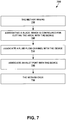
- Figure 7 depicts a flowchart 700 of a method for making a device, according to one embodiment.
- Figure 7 is described in the context of Figures 1-4 .
- a blade 101, 307, 407 which is configured for cutting the patient, is associated with the device 100, 200, 300, 400.
- the blade 101, 307, 407 can be made of various types of materials, such as various types of steel.
- the blade 101, 307, 407 may be straight, such as a razor blade, curved like a scalpel, or angled like an exacto knife.
- the blade 101, 307, 407 may be made of a single piece or multiple pieces of material.
- the blades 307, 407 depicted in Figures 3 and 4 are made of a single piece of material.
- the blades 101 depicted in Figures 1A , 1B , 2 may be made of a single piece of material where the single piece of material is configured with the FFC running through the single piece of material or may be made, for example, of two pieces that are attached to the FFC.
- a fluid flow channel 106, 206, 302, 402 is associated with the device 100, 200, 300, 400.
- the fluid flow channel 106, 206, 302, 402 is configured for the fluid to flow through the device 100, 200, 300, 400.
- the blade 101 may be configured to include the FFC 106, 206 or the blade 101 may be attached to another piece that includes the FFC 106, 206.
- a handle 309, 409 or a spine 411 may include the FFC 302, 402.
- the blade 307, 407 can then be attached to the handle 309, 409.
- any two or more of the blade, handle, spine and FFC may be made out of a single piece of material instead of attaching the various pieces, such as the blade and the handle, to each other.
- an inlet port 108, 301, 401 is associated with the device 100, 200, 300, 400.
- the inlet port 108, 301, 401 may be made out of separate piece of material that is attached to the device 100, 200, 300, 400.
- the inlet port 108, 301, 401 may be made out of the same piece of material as the rest of the device or may be made out of a separate piece of material as the rest of the device.
- the inlet port 301, 401 may be made out of the same piece of material as the handle 309, 409.
- the handle 309, 409 may or may not be made out of the same piece of material as the rest of the device. If the handle 309, 409 and the rest of the device are separate pieces of material, then they can be attached.
- the inlet port 108, 301, 401 and the fluid flow channel 106, 206 may be made out of the same piece of material as the blade 101.
- the inlet port 108, 301, 401 and the fluid flow channel 106, 206, 302, 402 can be made out of a different piece of material than the blade 101, 307, 407 where the blade 101, 307, 407 is then attached directly or indirectly to the inlet port fluid flow channel combination.
- the device 100, 200, 300, 400 is configured for fluid to flow from the inlet port 108, 301, 401 through the fluid flow channel 106, 206, 302, 402 and to exit an outlet 103, 305, 405 of the device 100, 200, 300, 400 for application to an area 532, for example, of a patient or an item.
- a device could be used to lubricate an area of an item, such as a piece of tubing, another medical device, among other things, and then cut inside of the area.
- a portion of the item would be an example of an area that fluid is applied to and that the blade is used to cut within.
- a device for applying medical fluid to an area and for cutting within the area includes an inlet port, a fluid flow channel, an outlet and a blade.
- the inlet port is configured for receiving the medical fluid into the device.
- the fluid flow channel is configured for the fluid to flow through the device.
- a first end of the fluid flow channel is connected to the inlet port.
- An outlet is configured for the fluid to come out of the device.
- the outlet is positioned at a second end of the fluid flow channel.
- the blade is configured for cutting within the area.
Landscapes
- Health & Medical Sciences (AREA)
- Life Sciences & Earth Sciences (AREA)
- Surgery (AREA)
- Molecular Biology (AREA)
- Engineering & Computer Science (AREA)
- Biomedical Technology (AREA)
- Heart & Thoracic Surgery (AREA)
- Medical Informatics (AREA)
- Nuclear Medicine, Radiotherapy & Molecular Imaging (AREA)
- Animal Behavior & Ethology (AREA)
- General Health & Medical Sciences (AREA)
- Public Health (AREA)
- Veterinary Medicine (AREA)
- Oral & Maxillofacial Surgery (AREA)
- Pathology (AREA)
- Surgical Instruments (AREA)
Description
- The present technology relates generally to medical devices for cutting a patient. More particularly, the present technology relates to applying medical fluid to an area and cutting within the area.
- Various types of cutting devices have been used, for example, to make incisions in patients. Examples of cutting devices include, but are not limited to, razor blades and scalpels.
-
EP 0 456 470 A1 discloses a device for applying medical fluid to an area and for cutting within the area. - The invention is described in claims 1 and 9. Preferred embodiments of the invention are described in the dependent claims.
-
-
Figure 1A depicts a device for applying fluid and cutting a patient from an angled view, according to one embodiment. -
Figure 1B depicts a top down view of the device, according to one embodiment. -
Figure 2 depicts a device with a multiple channel fluid flow channel, according to one embodiment. -
Figure 3 depicts a device with a handle, according to one embodiment. -
Figure 4 depicts a device with a spine, according to one embodiment. -
Figure 5 depicts a system for applying fluid and cutting a patient, according to one embodiment. -
Figure 6 depicts a flow chart for a method of using a device, according to one embodiment. -
Figure 7 depicts a flow chart for method of making a device, according to one embodiment. - The drawings referred to in this description should not be understood as being drawn to scale unless specifically noted.
- Before making an incision in an area of a patient, the area is sterilized with disinfectant fluid. The doctor takes a reservoir of medical fluid, such as a syringe with disinfectant in it, and applies the fluid to the patient. The doctor then has to remove the reservoir from their hand in order to grasp a cutting device with a blade. The operation of picking up the reservoir, putting the reservoir down, then picking up the cutting device is awkward and can lead to errors. Therefore, according to one embodiment, a device is provided that can be used for both applying the fluid and cutting, as will become more evident. According to one embodiment, a device is provided that can be used to improve the health of the patient.
- Although various embodiments are described in the context of the fluid being a disinfectant, embodiments are well suited to other types of fluid, such as lubricant or solvent. According to one embodiment, the fluid is intended for medical use. According to one embodiment, the fluid is sterile.
-
Figure 1A depicts adevice 100 for applying fluid and cutting a patient from an angled view, according to one embodiment.Figure 1B depicts a top down view of thedevice 100, according to one embodiment. Thedevice 100 includes aninlet port 108, a fluid flow channel (FFC) 106, anoutlet 103, and ablade 101. - The
device 100 includes ablade 101 for cutting the patient.Figures 1A ,1B depict ablade 101 with a straight cutting edge. However, embodiments are well suited for other blade configurations. For example, theblade 101 may be curved. Theblade 101 may be made out of various types of materials, such as different types of metal. - As depicted in
Figures 1A ,1B , theblade 101 is similar to a razor blade. However, embodiments are well suited for blade configurations that are similar to other types of cutting devices, such as a scalpel or an exacto knife, among other things. - As depicted in
Figures 1A ,1B , thedevice 100 does not include a separate handle. However, embodiments are well suited to adevice 100 that includes a handle. - The
inlet port 108 is configured for receiving the fluid into thedevice 100. For example, theinlet port 108 can be configured to receive fluid from a reservoir of fluid. Examples of reservoirs include, but are not limited to, a syringe or a bottle. An outlet port of the reservoir may be inserted into thedevice 100's inlet port 108. Theinlet port 108 may be designed to function with a particular type of reservoir. For example, the size and shape of the inlet port may be compatible with a reservoir's outlet port. In another example, theinlet port 108 may have threads that, that for example, mate with threads associated with the reservoir's outlet. However, theinlet port 108 may not have threads. - In another embodiment, the
inlet port 108 may be a universal port that is designed to function with a wide variety of reservoirs. The size and shape of theinlet port 108 may be designed to be large enough to accommodate a wide variety of reservoirs. Thedevice 100's inlet port 108 may have material that expands when a reservoir's outlet port is inserted into thedevice 100's inlet port 108 and contracts, for example, when the reservoir's outlet port is extracted from thedevice 100'sinlet port 108. - As depicted in
Figures 1A and1B , theinlet port 108 is oriented in the center of thenon-cutting edge 107 that is opposite thecutting edge 102. However, embodiments are well suited for other orientations of theinlet port 108. For example, theinlet port 108 may be positioned on any non-cuttingedge device 100. More specifically, theinlet port 108 may be positioned on aside device 100, aside blade 101, on a handle of the device, on a spine of the device, among other things. Further, theinlet port 108 may be oriented at any position along anedge inlet port 108 may be located in the center of anedge edge - The
fluid flow channel 106 includes afirst end 121 that is connected to theinlet port 108. Thedevice 100 also includes afluid flow channel 106 configured for the fluid to flow through thedevice 100. According to one embodiment, thefluid flow channel 106 is a narrow channel. As depicted inFigures 1A and1B , thedevice 100 includes asingle FFC 106. However, embodiments are well suited for a plurality of FFCs, for example, to more evenly distribute the fluid, as will become more evident. - As depicted in
Figure 1A , theFFC 106 is straight and is located down the center of theblade 101. However, embodiments are well suited for other orientations and configurations of the FFC 106. For example, theFFC 106 may be non-straight, theFFC 106 may be bent, theFFC 106 may be located off of the center of thedevice 100 or theblade 101, theFFC 106 may be located on theblade 101 or off of theblade 101, theFFC 106 may be located in a handle or a spine of a device. - An
outlet 103 is at theother end 122 of theFFC 106 where the fluid exits theFFC 106. As depicted inFigures 1A ,1B theoutlet 103 is located in the center of thecutting edge 102. - Embodiments are well suited to other orientations for the
outlet 103. For example, theoutlet 103 may be located on acutting edge 102 or anon-cutting edge outlet 103 may be oriented at any position along acutting edge 102 ornon-cutting edge outlet 103 may be located in the center of an edge, off of the center of the edge, on a tip of the device, the blade, or spine, at any position along a handle, blade or a spine, among other things. According to the invention, the outlet is formed on a cutting edge of the blade. - An
outlet 103 may be the same width as theFFC 106, wider than theFFC 106, or narrower than theFFC 106. According to the invention, the outlet is wider than the fluid flow channel. -
Figure 2 depicts adevice 200 with a multiple channel fluid flow channel, according to one embodiment. As depicted inFigure 2 , the device includes a FFC 206 withmultiple channels 206a-206d. The FFC 206 initially includes asingle channel 206a, which is connected to theinlet port 108, and thesingle channel 206a then branches intomultiple channels 206b-206d.Multiple outlets 103 can oriented evenly or unevenly along anedge 102. - According to other embodiments, the FFC may include several channels that connect with the
inlet port 108. Embodiments are well suited for other orientations and locations of a multiple channel FFC. -
Figure 3 depicts adevice 300 with ahandle 309, according to one embodiment. For example, thedevice 300 includes ahandle 309, aFFC 302, aninlet port 301, anoutlet 305 and ablade 307. Theblade 307 is attached to one end of thehandle 309. Theinlet port 301 is connected to the other end of thehandle 309. Theoutlet 305 is oriented on the side of thedevice 300 and at one end of thehandle 309. Thefluid flow channel 302 runs through thehandle 309 and is bent. Oneedge 308 of theblade 307 is curved. - As depicted in
Figure 3 , theinlet port 301 is oriented approximately toward the center of one end of thehandle 309. Similarly, theFFC 302 is oriented approximately in the center of thehandle 309. However, embodiments are well suited to other orientations of theinlet port 301 and theFFC 302. - Although
Figure 3 depicts thehandle 309 attached to one end of theblade 307, embodiments are well suited for thehandle 309 to be located at other locations and in other orientations. For example, a handle could be oriented along a non-cutting edge such as thenon-cutting edges device 100 depicted inFigures 1A ,1B . -
Figure 4 depicts adevice 400 with aspine 411, according to one embodiment. For example, thedevice 400 includes ahandle 409, aspine 411, aFFC 402, aninlet port 401, anoutlet 405 and ablade 407. Theblade 407 is oriented toward one end of thehandle 409, according to one embodiment. Theinlet port 401 is oriented toward the other end of thehandle 409. Thedevice 400 includes aspine 411 that runs along the top 410 of thehandle 409 and thenon-cutting edge 404 of theblade 407. TheFFC 402 runs through thespine 411, according to one embodiment. Thespine 411 may be part of thehandle 409 or may be separate from thehandle 409. Theinlet port 401, according to one embodiment, is aligned with theFFC 402 that runs through thespine 411. - As depicted in
Figures 1A ,2 ,3 , and4 examples of cutting edges include cuttingedges edges -
Figure 5 depicts asystem 500 for applying fluid to anarea 532 and for cutting within thearea 532, according to one embodiment.System 500 depicts areservoir 510, such as a syringe and adevice 520. Thereservoir 510 is connected with thedevice 520. For example, anoutlet port 511 associated with thereservoir 510 is inserted into thedevice 520'sinlet port 523. Fluid can be delivered from thereservoir 510, through thedevice 520, out the device'soutlet 522 and to anarea 532 of thepatient 530. Anincision 531 is depicted within thearea 532 of thepatient 530 using thedevice 520'sblade 521. Theincision 531 in thepatient 530 may be any depth or length depending on the type of procedure being performed on thepatient 530. -
Figure 6 depicts aflow chart 600 of a method for using a device, according to one embodiment.Figure 6 is described in the context ofFigure 5 . - At 610, the method begins.
- At 620, an
inlet port 523 of thedevice 520 is connected to areservoir 510 of fluid. As depicted inFigure 5 , theoutlet port 511 of areservoir 510, such as a syringe, is inserted into thedevice 520'sinlet port 523. - The
device 520 has afluid flow channel 524 for the fluid to flow through thedevice 520, anoutlet 522 for the fluid to exit thedevice 520 for application to anarea 532, for example, of apatient 530, and ablade 521 for cutting within thearea 532. - At 630, the fluid is made to flow from the
reservoir 510 into theinlet port 523 through thefluid flow channel 524 and exit theoutlet 522. Thedevice 520'sinlet port 523 receives the fluid from thereservoir 510. For example, a doctor or clinician pushes the syringe'splunger 512 causing the fluid to flow out of thesyringe 510'soutlet port 511 and into thedevice 520'sinlet port 523. The fluid proceeds to flow through thedevice 520'sFFC 524 and out thedevice 520'soutlet 522 onto thearea 532 of thepatient 530. Although embodiments have been described in the context of a person pushing aplunger 512 to deliver medical fluid, embodiments are well suited to other actions for causing the fluid to be delivered. For example, a bottle containing medical fluid could be squeezed. - At 640, the
area 532 is cut with theblade 521. For example, theblade 521 is used to make theincision 531 within thearea 532 of thepatient 530. - At 650, the method ends.
- The doctor or clinician can use an edge of the
device 520 to distribute the fluid evenly in anarea 532 on the patient, for example, before theblade 521 is used to make theincision 531 in thatarea 532. -
Figure 7 depicts aflowchart 700 of a method for making a device, according to one embodiment.Figure 7 is described in the context ofFigures 1-4 . - At 710, the method begins.
- At 720, a
blade device blade blade blade blades Figures 3 and4 are made of a single piece of material. Theblades 101 depicted inFigures 1A ,1B ,2 may be made of a single piece of material where the single piece of material is configured with the FFC running through the single piece of material or may be made, for example, of two pieces that are attached to the FFC. - At 730, a
fluid flow channel device fluid flow channel device Figures 1A ,1B ,2 theblade 101 may be configured to include theFFC 106, 206 or theblade 101 may be attached to another piece that includes theFFC 106, 206. Referring toFigures 3 and4 , ahandle spine 411 may include theFFC blade handle - At 740, an
inlet port device inlet port device inlet port inlet port handle handle handle - The
inlet port fluid flow channel 106, 206 may be made out of the same piece of material as theblade 101. Theinlet port fluid flow channel blade blade - The
device inlet port fluid flow channel outlet device area 532, for example, of a patient or an item. - At 750, the method ends.
- Although various embodiments have been described in the context of making an incision in a patient, various embodiments can be used for cutting something other than a patient. For example, a device could be used to lubricate an area of an item, such as a piece of tubing, another medical device, among other things, and then cut inside of the area. In this case, a portion of the item would be an example of an area that fluid is applied to and that the blade is used to cut within.
- Various embodiments have been described in various combinations and illustrations. However, any two or more embodiments or features may be combined. Further, any embodiment or feature may be used separately from any other embodiment or feature. Phrases, such as "an embodiment," "one embodiment," among others, used herein, are not necessarily referring to the same embodiment. Features, structures, or characteristics of any embodiment may be combined in any suitable manner with one or more other features, structures, or characteristics.
- All elements, parts and steps described herein are preferably included. It is to be understood that any of these elements, parts and steps may be replaced by other elements, parts and steps or deleted altogether as will be obvious to those skilled in the art.
- Broadly, the description herein pertains to the following. A device for applying medical fluid to an area and for cutting within the area is provided. The device includes an inlet port, a fluid flow channel, an outlet and a blade. The inlet port is configured for receiving the medical fluid into the device. The fluid flow channel is configured for the fluid to flow through the device. A first end of the fluid flow channel is connected to the inlet port. An outlet is configured for the fluid to come out of the device. The outlet is positioned at a second end of the fluid flow channel. The blade is configured for cutting within the area.
Claims (13)
- A device (100) for applying medical fluid to an area and for cutting within the area, the device (100) comprising:an inlet port (108) configured for receiving the medical fluid into the device (100);a fluid flow channel (106) configured for the medical fluid to flow through the device (100), a first end of the fluid flow channel (106) connected to the inlet port (108);an outlet (103) configured for the medical fluid to come out of the device (100), the outlet (103) being positioned at a second end of the fluid flow channel (106); anda blade configured for cutting in the area that the medical fluid has been applied to, the outlet (103) being formed on a cutting edge of the blade, characterized in that,that the outlet (103) is wider than the fluid flow channel (106).
- The device (100) of Claim 1, wherein the inlet port (108) mates with an outlet port of a fluid reservoir.
- The device (100) of Claim 2, wherein the inlet port (108) has threads that mate with threads of the outlet port.
- The device (100) of Claim 1, wherein the inlet port (108) is a universal inlet port (108) that is compatible with various types of fluid reservoir outlet ports.
- The device (100) of Claim 1, wherein the fluid flow channel (106) is selected from a group consisting of a straight fluid flow channel (106), a bent fluid flow channel (106), and a fluid flow channel (106) with multiple channels.
- The device (100) of Claim 1, wherein the fluid flow channel (106) is located in one of group consisting of the blade, and a handle.
- The device (100) of Claim 1, wherein the outlet (103) is located at the tip of the blade.
- The device (100) of Claim 1, wherein a location of the outlet (103) is selected from locations consisting of a center of an edge and off center of the edge.
- A method of making a device (100) for applying medical fluid to an area of a patient and for cutting in the area of the patient, the method comprising:associating a blade, which is configured for cutting within the area of the patient, with the device (100);associating a fluid flow channel (106) with the device (100), wherein the fluid flow channel (106) is configured for the medical fluid to flow through the device (100);associating an inlet port (108) with the device (100); andassociating a handle with the device (100), wherein the device (100) is configured for fluid to flow from the inlet port (108) through the fluid flow channel (106) to an outlet (103) that is wider than the fluid flow channel (106) for application to the area of the patient, said outlet (103) being formed on a cutting edge of the blade.
- The method as recited by Claim 9, wherein the method further comprises: making the blade, the fluid flow channel (106) and the inlet port (108) out of a single piece of material.
- The method as recited by Claim 9, wherein the fluid flow path is located, at least in part, in the handle.
- The method as recited by Claim 9, wherein the method further comprises: making the blade, the fluid flow channel (106), the inlet port (108) and the handle out of a single piece of material.
- The method as recited by Claim 9, wherein the method further comprises:making a first piece that includes the fluid flow channel (106), the inlet port (108) and the handle out of a first piece of material;making the blade out of a second piece of material; andconnecting the first piece with the blade.
Applications Claiming Priority (2)
| Application Number | Priority Date | Filing Date | Title |
|---|---|---|---|
| US13/274,980 US9427253B2 (en) | 2011-10-17 | 2011-10-17 | Device for applying medical fluid to an area and for cutting within the area |
| PCT/US2012/060308 WO2013059140A1 (en) | 2011-10-17 | 2012-10-15 | Device for applying medical fluid to and cutting within an area |
Publications (3)
| Publication Number | Publication Date |
|---|---|
| EP2768552A1 EP2768552A1 (en) | 2014-08-27 |
| EP2768552A4 EP2768552A4 (en) | 2015-06-24 |
| EP2768552B1 true EP2768552B1 (en) | 2018-07-25 |
Family
ID=48086457
Family Applications (1)
| Application Number | Title | Priority Date | Filing Date |
|---|---|---|---|
| EP12841119.6A Not-in-force EP2768552B1 (en) | 2011-10-17 | 2012-10-15 | Device for applying medical fluid to and cutting within an area |
Country Status (3)
| Country | Link |
|---|---|
| US (1) | US9427253B2 (en) |
| EP (1) | EP2768552B1 (en) |
| WO (1) | WO2013059140A1 (en) |
Families Citing this family (4)
| Publication number | Priority date | Publication date | Assignee | Title |
|---|---|---|---|---|
| US20160143660A1 (en) * | 2013-06-26 | 2016-05-26 | 3M Innovative Properties Company | Curette head and methods of use thereof |
| US20180100275A1 (en) * | 2016-10-11 | 2018-04-12 | Caterpillar Paving Products Inc. | Scraper for cleaning drum surface of compactor |
| AU2018217263B1 (en) * | 2018-08-15 | 2019-05-02 | Larboard Pty Ltd | Device and method for delivering fluids during surgery |
| USD901810S1 (en) * | 2019-06-25 | 2020-11-10 | Hong Ann Tool Industries Co., Ltd. | Blade |
Family Cites Families (37)
| Publication number | Priority date | Publication date | Assignee | Title |
|---|---|---|---|---|
| US878524A (en) * | 1907-09-24 | 1908-02-11 | White John H | Surgeon's knife. |
| US1333745A (en) * | 1919-08-04 | 1920-03-16 | Kalmus Comstock & Wescott Inc | Trocar |
| US1484618A (en) * | 1922-04-12 | 1924-02-26 | Blades Robert | Skinning knife |
| US3786814A (en) * | 1972-12-15 | 1974-01-22 | T Armao | Method of preventing cryoadhesion of cryosurgical instruments and cryosurgical instruments |
| US4297765A (en) * | 1980-03-17 | 1981-11-03 | Wilbur E. Altman | Fish scaler with water handle |
| US4858324A (en) * | 1984-01-11 | 1989-08-22 | Edge Engineering, Inc. | Knife blades and method of making said knife blades |
| DE8421994U1 (en) | 1984-07-24 | 1985-11-14 | Schettler, Jürgen, 7500 Karlsruhe | Cutting device |
| JPS6266848A (en) * | 1985-09-20 | 1987-03-26 | 住友ベークライト株式会社 | Surgical operation appliance |
| CA2042006C (en) | 1990-05-11 | 1995-08-29 | Morito Idemoto | Surgical ultrasonic horn |
| US5288274A (en) * | 1992-07-08 | 1994-02-22 | Bell Harry H | Knife |
| DE4227369C1 (en) | 1992-08-19 | 1994-02-17 | Wolfgang Daum | Surgical knife with suction unit - has tubular blade flattened and ground at one end and connected to suction unit at other, has channels for fluid feed inside tube |
| US5460182A (en) * | 1992-09-14 | 1995-10-24 | Sextant Medical Corporation | Tissue penetrating apparatus and methods |
| US5403318A (en) * | 1993-01-15 | 1995-04-04 | Boehringer Laboratories, Inc. | Apparatus and method for shaping bone |
| US5782851A (en) * | 1996-04-10 | 1998-07-21 | Rassman; William R. | Hair transplantation system |
| US5571071A (en) * | 1995-08-08 | 1996-11-05 | Shapiro; Jeffrey M. | Laryngoscope blade including means for dispensing topical anesthetic |
| US5890630A (en) * | 1997-09-05 | 1999-04-06 | Lobdell; Raymond J. | Device for dispensing flowable food products |
| US5843108A (en) * | 1997-10-23 | 1998-12-01 | Samuels; Shaun Laurence Wilkie | Over the wire scapel |
| US5894959A (en) * | 1997-11-17 | 1999-04-20 | Sigurlidason; Sigurdur Ragnar | Viscous substance dispensing knife |
| US6363940B1 (en) * | 1998-05-14 | 2002-04-02 | Calypso Medical Technologies, Inc. | System and method for bracketing and removing tissue |
| US6592564B2 (en) * | 1999-07-23 | 2003-07-15 | Vasca, Inc. | Methods and kits for locking and disinfecting implanted catheters |
| US6224574B1 (en) * | 1999-10-18 | 2001-05-01 | Hassan Al-Labban | Combined scalpel and syringe device |
| US6379371B1 (en) * | 1999-11-15 | 2002-04-30 | Misonix, Incorporated | Ultrasonic cutting blade with cooling |
| US6352465B1 (en) * | 2000-08-25 | 2002-03-05 | Kirk D. Heymann | Toy knife |
| US6716228B2 (en) | 2000-09-30 | 2004-04-06 | Yale University | Surgical access device |
| US7108681B2 (en) * | 2000-10-16 | 2006-09-19 | Corium International, Inc. | Microstructures for delivering a composition cutaneously to skin |
| US6722364B2 (en) * | 2001-01-12 | 2004-04-20 | Becton, Dickinson And Company | Medicament inhalation delivery devices and methods for using the same |
| WO2002083003A1 (en) * | 2001-04-11 | 2002-10-24 | Clarke Dana S | Tissue structure identification in advance of instrument |
| US20040087992A1 (en) * | 2002-08-09 | 2004-05-06 | Vladimir Gartstein | Microstructures for delivering a composition cutaneously to skin using rotatable structures |
| US6960225B1 (en) * | 2002-07-22 | 2005-11-01 | Uop Llc | Medical applications using microcombustion |
| US6824555B1 (en) * | 2002-07-22 | 2004-11-30 | Uop Llc | Combustion needle for medical applications |
| US7666186B2 (en) * | 2002-09-27 | 2010-02-23 | Surgitech, Llc | Surgical system with a blade |
| FR2846871B1 (en) * | 2002-11-08 | 2005-01-21 | Micro Mega Int Mfg Sa | PERIODONTAL TREATMENT INSTRUMENT. |
| US7066936B2 (en) * | 2004-06-07 | 2006-06-27 | Ethicon, Inc. | Surgical cutting and tissue vaporizing instrument |
| WO2008148139A1 (en) | 2007-06-08 | 2008-12-11 | Angelo Troedhan | Ultrasonic scalpel |
| US7625268B2 (en) * | 2007-12-24 | 2009-12-01 | Earl Durjan | Fish cleaning apparatus |
| US20100274236A1 (en) * | 2009-04-23 | 2010-10-28 | Krimsky William S | Apparatuses and methods for applying a cryogenic effect to tissue and cutting tissue |
| US8051570B1 (en) * | 2009-05-20 | 2011-11-08 | Amanda Brown | Multi-use kitchen utility knife |
-
2011
- 2011-10-17 US US13/274,980 patent/US9427253B2/en not_active Expired - Fee Related
-
2012
- 2012-10-15 EP EP12841119.6A patent/EP2768552B1/en not_active Not-in-force
- 2012-10-15 WO PCT/US2012/060308 patent/WO2013059140A1/en not_active Ceased
Non-Patent Citations (1)
| Title |
|---|
| None * |
Also Published As
| Publication number | Publication date |
|---|---|
| WO2013059140A1 (en) | 2013-04-25 |
| US9427253B2 (en) | 2016-08-30 |
| EP2768552A4 (en) | 2015-06-24 |
| US20130096487A1 (en) | 2013-04-18 |
| EP2768552A1 (en) | 2014-08-27 |
Similar Documents
| Publication | Publication Date | Title |
|---|---|---|
| AU2017315323B2 (en) | A device for obtaining a blood sample | |
| US11117282B2 (en) | Guide catheter slitter | |
| US12207805B2 (en) | Flexible tissue collection device | |
| EP2768552B1 (en) | Device for applying medical fluid to and cutting within an area | |
| KR20210129120A (en) | Capillary collector with rotatable connection | |
| AU2015315576B2 (en) | Method for resection of tumors and tissues | |
| EP3190993B1 (en) | Tumor margin device | |
| US9907546B2 (en) | Surgical elevator with suction | |
| US8425546B2 (en) | Up cutting knife with suction | |
| WO2018195482A1 (en) | Ergonomic scalpel | |
| KR101696696B1 (en) | overtube AND USES THEREOF | |
| US7632254B1 (en) | Device for splitting the tubular body of a catheter or sheath | |
| EP3510950B1 (en) | Nose knife | |
| CN202342142U (en) | Combined scalpel | |
| CN206151573U (en) | Function was peeled off in area nasal cavity electrical cutter head for minimal access surgery | |
| WO2004080274A3 (en) | Insufflator and method of use | |
| US20250000543A1 (en) | Surgical blade for performing cutting and suction | |
| US20170266409A9 (en) | Process and System of Matching Harvesting and Reinjection Cannulas for Use in Removal and Reinjection Procedures of Adipose Tissue, Other Tissues, and Fluids Commonly Called Liposuction | |
| CN107157535A (en) | It is multifunctional assembled to cut | |
| HK40001744A (en) | Nose knife |
Legal Events
| Date | Code | Title | Description |
|---|---|---|---|
| PUAI | Public reference made under article 153(3) epc to a published international application that has entered the european phase |
Free format text: ORIGINAL CODE: 0009012 |
|
| 17P | Request for examination filed |
Effective date: 20140515 |
|
| AK | Designated contracting states |
Kind code of ref document: A1 Designated state(s): AL AT BE BG CH CY CZ DE DK EE ES FI FR GB GR HR HU IE IS IT LI LT LU LV MC MK MT NL NO PL PT RO RS SE SI SK SM TR |
|
| DAX | Request for extension of the european patent (deleted) | ||
| RA4 | Supplementary search report drawn up and despatched (corrected) |
Effective date: 20150528 |
|
| RIC1 | Information provided on ipc code assigned before grant |
Ipc: A61B 19/00 20060101ALI20150521BHEP Ipc: A61M 5/32 20060101ALI20150521BHEP Ipc: A61B 17/3209 20060101ALI20150521BHEP Ipc: A61B 17/32 20060101ALI20150521BHEP Ipc: A61M 5/14 20060101AFI20150521BHEP |
|
| GRAP | Despatch of communication of intention to grant a patent |
Free format text: ORIGINAL CODE: EPIDOSNIGR1 |
|
| RIC1 | Information provided on ipc code assigned before grant |
Ipc: A61M 5/32 20060101ALI20180220BHEP Ipc: A61M 5/14 20060101AFI20180220BHEP Ipc: A61B 17/3209 20060101ALI20180220BHEP Ipc: A61B 90/00 20160101ALI20180220BHEP Ipc: A61B 17/32 20060101ALI20180220BHEP |
|
| INTG | Intention to grant announced |
Effective date: 20180307 |
|
| GRAS | Grant fee paid |
Free format text: ORIGINAL CODE: EPIDOSNIGR3 |
|
| GRAA | (expected) grant |
Free format text: ORIGINAL CODE: 0009210 |
|
| AK | Designated contracting states |
Kind code of ref document: B1 Designated state(s): AL AT BE BG CH CY CZ DE DK EE ES FI FR GB GR HR HU IE IS IT LI LT LU LV MC MK MT NL NO PL PT RO RS SE SI SK SM TR |
|
| REG | Reference to a national code |
Ref country code: GB Ref legal event code: FG4D |
|
| REG | Reference to a national code |
Ref country code: CH Ref legal event code: EP |
|
| REG | Reference to a national code |
Ref country code: AT Ref legal event code: REF Ref document number: 1021077 Country of ref document: AT Kind code of ref document: T Effective date: 20180815 |
|
| REG | Reference to a national code |
Ref country code: DE Ref legal event code: R096 Ref document number: 602012048977 Country of ref document: DE |
|
| REG | Reference to a national code |
Ref country code: IE Ref legal event code: FG4D |
|
| REG | Reference to a national code |
Ref country code: FR Ref legal event code: PLFP Year of fee payment: 7 |
|
| REG | Reference to a national code |
Ref country code: NL Ref legal event code: MP Effective date: 20180725 |
|
| REG | Reference to a national code |
Ref country code: LT Ref legal event code: MG4D |
|
| PG25 | Lapsed in a contracting state [announced via postgrant information from national office to epo] |
Ref country code: NL Free format text: LAPSE BECAUSE OF FAILURE TO SUBMIT A TRANSLATION OF THE DESCRIPTION OR TO PAY THE FEE WITHIN THE PRESCRIBED TIME-LIMIT Effective date: 20180725 |
|
| REG | Reference to a national code |
Ref country code: AT Ref legal event code: MK05 Ref document number: 1021077 Country of ref document: AT Kind code of ref document: T Effective date: 20180725 |
|
| PG25 | Lapsed in a contracting state [announced via postgrant information from national office to epo] |
Ref country code: GR Free format text: LAPSE BECAUSE OF FAILURE TO SUBMIT A TRANSLATION OF THE DESCRIPTION OR TO PAY THE FEE WITHIN THE PRESCRIBED TIME-LIMIT Effective date: 20181026 Ref country code: BG Free format text: LAPSE BECAUSE OF FAILURE TO SUBMIT A TRANSLATION OF THE DESCRIPTION OR TO PAY THE FEE WITHIN THE PRESCRIBED TIME-LIMIT Effective date: 20181025 Ref country code: NO Free format text: LAPSE BECAUSE OF FAILURE TO SUBMIT A TRANSLATION OF THE DESCRIPTION OR TO PAY THE FEE WITHIN THE PRESCRIBED TIME-LIMIT Effective date: 20181025 Ref country code: AT Free format text: LAPSE BECAUSE OF FAILURE TO SUBMIT A TRANSLATION OF THE DESCRIPTION OR TO PAY THE FEE WITHIN THE PRESCRIBED TIME-LIMIT Effective date: 20180725 Ref country code: PL Free format text: LAPSE BECAUSE OF FAILURE TO SUBMIT A TRANSLATION OF THE DESCRIPTION OR TO PAY THE FEE WITHIN THE PRESCRIBED TIME-LIMIT Effective date: 20180725 Ref country code: RS Free format text: LAPSE BECAUSE OF FAILURE TO SUBMIT A TRANSLATION OF THE DESCRIPTION OR TO PAY THE FEE WITHIN THE PRESCRIBED TIME-LIMIT Effective date: 20180725 Ref country code: IS Free format text: LAPSE BECAUSE OF FAILURE TO SUBMIT A TRANSLATION OF THE DESCRIPTION OR TO PAY THE FEE WITHIN THE PRESCRIBED TIME-LIMIT Effective date: 20181125 Ref country code: FI Free format text: LAPSE BECAUSE OF FAILURE TO SUBMIT A TRANSLATION OF THE DESCRIPTION OR TO PAY THE FEE WITHIN THE PRESCRIBED TIME-LIMIT Effective date: 20180725 Ref country code: LT Free format text: LAPSE BECAUSE OF FAILURE TO SUBMIT A TRANSLATION OF THE DESCRIPTION OR TO PAY THE FEE WITHIN THE PRESCRIBED TIME-LIMIT Effective date: 20180725 Ref country code: SE Free format text: LAPSE BECAUSE OF FAILURE TO SUBMIT A TRANSLATION OF THE DESCRIPTION OR TO PAY THE FEE WITHIN THE PRESCRIBED TIME-LIMIT Effective date: 20180725 |
|
| PG25 | Lapsed in a contracting state [announced via postgrant information from national office to epo] |
Ref country code: AL Free format text: LAPSE BECAUSE OF FAILURE TO SUBMIT A TRANSLATION OF THE DESCRIPTION OR TO PAY THE FEE WITHIN THE PRESCRIBED TIME-LIMIT Effective date: 20180725 Ref country code: HR Free format text: LAPSE BECAUSE OF FAILURE TO SUBMIT A TRANSLATION OF THE DESCRIPTION OR TO PAY THE FEE WITHIN THE PRESCRIBED TIME-LIMIT Effective date: 20180725 Ref country code: LV Free format text: LAPSE BECAUSE OF FAILURE TO SUBMIT A TRANSLATION OF THE DESCRIPTION OR TO PAY THE FEE WITHIN THE PRESCRIBED TIME-LIMIT Effective date: 20180725 |
|
| REG | Reference to a national code |
Ref country code: DE Ref legal event code: R097 Ref document number: 602012048977 Country of ref document: DE |
|
| PG25 | Lapsed in a contracting state [announced via postgrant information from national office to epo] |
Ref country code: ES Free format text: LAPSE BECAUSE OF FAILURE TO SUBMIT A TRANSLATION OF THE DESCRIPTION OR TO PAY THE FEE WITHIN THE PRESCRIBED TIME-LIMIT Effective date: 20180725 Ref country code: IT Free format text: LAPSE BECAUSE OF FAILURE TO SUBMIT A TRANSLATION OF THE DESCRIPTION OR TO PAY THE FEE WITHIN THE PRESCRIBED TIME-LIMIT Effective date: 20180725 Ref country code: RO Free format text: LAPSE BECAUSE OF FAILURE TO SUBMIT A TRANSLATION OF THE DESCRIPTION OR TO PAY THE FEE WITHIN THE PRESCRIBED TIME-LIMIT Effective date: 20180725 Ref country code: CZ Free format text: LAPSE BECAUSE OF FAILURE TO SUBMIT A TRANSLATION OF THE DESCRIPTION OR TO PAY THE FEE WITHIN THE PRESCRIBED TIME-LIMIT Effective date: 20180725 Ref country code: EE Free format text: LAPSE BECAUSE OF FAILURE TO SUBMIT A TRANSLATION OF THE DESCRIPTION OR TO PAY THE FEE WITHIN THE PRESCRIBED TIME-LIMIT Effective date: 20180725 |
|
| PG25 | Lapsed in a contracting state [announced via postgrant information from national office to epo] |
Ref country code: SM Free format text: LAPSE BECAUSE OF FAILURE TO SUBMIT A TRANSLATION OF THE DESCRIPTION OR TO PAY THE FEE WITHIN THE PRESCRIBED TIME-LIMIT Effective date: 20180725 Ref country code: DK Free format text: LAPSE BECAUSE OF FAILURE TO SUBMIT A TRANSLATION OF THE DESCRIPTION OR TO PAY THE FEE WITHIN THE PRESCRIBED TIME-LIMIT Effective date: 20180725 Ref country code: SK Free format text: LAPSE BECAUSE OF FAILURE TO SUBMIT A TRANSLATION OF THE DESCRIPTION OR TO PAY THE FEE WITHIN THE PRESCRIBED TIME-LIMIT Effective date: 20180725 |
|
| PLBE | No opposition filed within time limit |
Free format text: ORIGINAL CODE: 0009261 |
|
| REG | Reference to a national code |
Ref country code: CH Ref legal event code: PL |
|
| STAA | Information on the status of an ep patent application or granted ep patent |
Free format text: STATUS: NO OPPOSITION FILED WITHIN TIME LIMIT |
|
| REG | Reference to a national code |
Ref country code: BE Ref legal event code: MM Effective date: 20181031 |
|
| PG25 | Lapsed in a contracting state [announced via postgrant information from national office to epo] |
Ref country code: LU Free format text: LAPSE BECAUSE OF NON-PAYMENT OF DUE FEES Effective date: 20181015 Ref country code: MC Free format text: LAPSE BECAUSE OF FAILURE TO SUBMIT A TRANSLATION OF THE DESCRIPTION OR TO PAY THE FEE WITHIN THE PRESCRIBED TIME-LIMIT Effective date: 20180725 |
|
| 26N | No opposition filed |
Effective date: 20190426 |
|
| REG | Reference to a national code |
Ref country code: IE Ref legal event code: MM4A |
|
| PG25 | Lapsed in a contracting state [announced via postgrant information from national office to epo] |
Ref country code: SI Free format text: LAPSE BECAUSE OF FAILURE TO SUBMIT A TRANSLATION OF THE DESCRIPTION OR TO PAY THE FEE WITHIN THE PRESCRIBED TIME-LIMIT Effective date: 20180725 Ref country code: LI Free format text: LAPSE BECAUSE OF NON-PAYMENT OF DUE FEES Effective date: 20181031 Ref country code: CH Free format text: LAPSE BECAUSE OF NON-PAYMENT OF DUE FEES Effective date: 20181031 Ref country code: BE Free format text: LAPSE BECAUSE OF NON-PAYMENT OF DUE FEES Effective date: 20181031 |
|
| PG25 | Lapsed in a contracting state [announced via postgrant information from national office to epo] |
Ref country code: IE Free format text: LAPSE BECAUSE OF NON-PAYMENT OF DUE FEES Effective date: 20181015 |
|
| PG25 | Lapsed in a contracting state [announced via postgrant information from national office to epo] |
Ref country code: MT Free format text: LAPSE BECAUSE OF NON-PAYMENT OF DUE FEES Effective date: 20181015 |
|
| PG25 | Lapsed in a contracting state [announced via postgrant information from national office to epo] |
Ref country code: TR Free format text: LAPSE BECAUSE OF FAILURE TO SUBMIT A TRANSLATION OF THE DESCRIPTION OR TO PAY THE FEE WITHIN THE PRESCRIBED TIME-LIMIT Effective date: 20180725 |
|
| PG25 | Lapsed in a contracting state [announced via postgrant information from national office to epo] |
Ref country code: PT Free format text: LAPSE BECAUSE OF FAILURE TO SUBMIT A TRANSLATION OF THE DESCRIPTION OR TO PAY THE FEE WITHIN THE PRESCRIBED TIME-LIMIT Effective date: 20180725 |
|
| PG25 | Lapsed in a contracting state [announced via postgrant information from national office to epo] |
Ref country code: CY Free format text: LAPSE BECAUSE OF FAILURE TO SUBMIT A TRANSLATION OF THE DESCRIPTION OR TO PAY THE FEE WITHIN THE PRESCRIBED TIME-LIMIT Effective date: 20180725 Ref country code: HU Free format text: LAPSE BECAUSE OF FAILURE TO SUBMIT A TRANSLATION OF THE DESCRIPTION OR TO PAY THE FEE WITHIN THE PRESCRIBED TIME-LIMIT; INVALID AB INITIO Effective date: 20121015 Ref country code: MK Free format text: LAPSE BECAUSE OF NON-PAYMENT OF DUE FEES Effective date: 20180725 |
|
| PGFP | Annual fee paid to national office [announced via postgrant information from national office to epo] |
Ref country code: FR Payment date: 20200917 Year of fee payment: 9 Ref country code: GB Payment date: 20200921 Year of fee payment: 9 |
|
| PGFP | Annual fee paid to national office [announced via postgrant information from national office to epo] |
Ref country code: DE Payment date: 20200917 Year of fee payment: 9 |
|
| REG | Reference to a national code |
Ref country code: DE Ref legal event code: R119 Ref document number: 602012048977 Country of ref document: DE |
|
| GBPC | Gb: european patent ceased through non-payment of renewal fee |
Effective date: 20211015 |
|
| PG25 | Lapsed in a contracting state [announced via postgrant information from national office to epo] |
Ref country code: GB Free format text: LAPSE BECAUSE OF NON-PAYMENT OF DUE FEES Effective date: 20211015 Ref country code: DE Free format text: LAPSE BECAUSE OF NON-PAYMENT OF DUE FEES Effective date: 20220503 |
|
| PG25 | Lapsed in a contracting state [announced via postgrant information from national office to epo] |
Ref country code: FR Free format text: LAPSE BECAUSE OF NON-PAYMENT OF DUE FEES Effective date: 20211031 |