EP2768348B1 - Pusher mechanism and pusher mechanism guide, merchandise display system comprising such a pusher mechanism and pusher mechanism guide and a method for displaying merchandise using such a merchandise display system - Google Patents
Pusher mechanism and pusher mechanism guide, merchandise display system comprising such a pusher mechanism and pusher mechanism guide and a method for displaying merchandise using such a merchandise display system Download PDFInfo
- Publication number
- EP2768348B1 EP2768348B1 EP13814353.2A EP13814353A EP2768348B1 EP 2768348 B1 EP2768348 B1 EP 2768348B1 EP 13814353 A EP13814353 A EP 13814353A EP 2768348 B1 EP2768348 B1 EP 2768348B1
- Authority
- EP
- European Patent Office
- Prior art keywords
- pusher
- guide
- folding panel
- pusher mechanism
- panel
- Prior art date
- Legal status (The legal status is an assumption and is not a legal conclusion. Google has not performed a legal analysis and makes no representation as to the accuracy of the status listed.)
- Active
Links
Images





















Classifications
-
- A—HUMAN NECESSITIES
- A47—FURNITURE; DOMESTIC ARTICLES OR APPLIANCES; COFFEE MILLS; SPICE MILLS; SUCTION CLEANERS IN GENERAL
- A47F—SPECIAL FURNITURE, FITTINGS, OR ACCESSORIES FOR SHOPS, STOREHOUSES, BARS, RESTAURANTS OR THE LIKE; PAYING COUNTERS
- A47F1/00—Racks for dispensing merchandise; Containers for dispensing merchandise
- A47F1/04—Racks or containers with arrangements for dispensing articles, e.g. by means of gravity or springs
- A47F1/12—Racks or containers with arrangements for dispensing articles, e.g. by means of gravity or springs dispensing from the side of an approximately horizontal stack
- A47F1/125—Racks or containers with arrangements for dispensing articles, e.g. by means of gravity or springs dispensing from the side of an approximately horizontal stack with an article-pushing device
- A47F1/126—Racks or containers with arrangements for dispensing articles, e.g. by means of gravity or springs dispensing from the side of an approximately horizontal stack with an article-pushing device the pushing device being urged by spring means
Definitions
- the invention relates generally to a shelf assembly for use in merchandising product and more particularly to a shelf assembly having improved mechanisms for displaying and pushing product on the shelves.
- known systems may include inclined trays or floors that through gravity will cause the product to move toward the front of the shelf.
- Many of these systems include floors or shelves made of a plastic material such as polypropylene that due its low coefficient of friction permit the product to easily slide along the inclined floor or surface.
- these surfaces can become obstructed with debris or sticky substances that inhibit the product from properly sliding, sometimes causing several products to tip over thus blocking additional product from moving to the front of the shelf.
- Other systems include the use of a pusher system to push the product toward the front of the shelf as the product at the front of the shelf is removed.
- the known pusher systems are typically mounted to a track and include a pusher paddle and a coiled spring to urge the product forward.
- the track becomes obstructed with dirt or sticky materials that hinder the proper operation of the pusher system in the track.
- the known pusher paddles may occasionally tip or bend backwards, thereby causing a binding of the pusher mechanism in the track. In those situations, the pusher mechanism may not properly push product toward the front of the shelf.
- US 2007/194037 A1 discloses a spring alignment mechanism that utilizes a guide inserted into a display carton below merchandise items.
- a spring-driven rear pull member travels on the guide so that as items are removed from the carton, remaining items are pulled forward.
- Merchandise items with rounded edges may rest on the directly on the carton, so that the guide may be inserted beneath the items.
- Other items may be supported on cardboard support ribs built into the bottom of the carton or provide on a carton insert.
- US 2012/234851 A1 discloses a product dispensing system including a container that defines an internal volume and an access opening into the internal volume, at least one product received in the internal volume and a biasing assembly extendable into the internal volume to urge the product toward the access opening, wherein the container is engaged with the biasing assembly when the biasing assembly extends into the internal volume.
- US 2012/118840 A1 discloses an apparatus for storing and displaying packages.
- a self-adjusting shelf comprises a sled coupled to a track, and at least two product supports located in a plane above the track. The product supports are aligned substantially parallel to the track and are coupled to the track. Packages rest upon the product supports. The sled slides along the length of the track. The sled urges, via either gravity or a biasing device, the sled forward against downstream packages. Thus, when one package is removed, the sled forces the remaining packages to the front of the shelf.
- One embodiment is directed at improving upon existing merchandising systems by providing a trackless pusher system that works with gravity-fed merchandise systems (i.e., inclined shelves or trays) and non-gravity-fed merchandise systems.
- a pusher mechanism for a merchandise display system as claimed in claim 1.
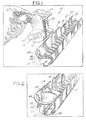
- FIG. 1 an isometric exploded view of an example merchandise system 10, which includes a product dispensing tray 12 in which is mounted a trackless pusher mechanism 14.
- the pusher mechanism 14 will fit in the tray 12 and will slide along the surface of the tray without the use of tracks, rails, or guides typically used to hold a conventional pusher mechanism to the tray or floor of the tray.
- the pusher mechanism defines a pusher paddle and a pusher floor that extends forward of the pusher paddle.
- a coiled spring may extend across the pusher floor and operatively connect to the tray at a forward position on the tray.
- product to be merchandised may be placed in the tray in front of the pusher paddle and may sit on the pusher floor as well as the coiled spring.
- the weight of the product will prevent the pusher paddle from tipping to ensure proper pushing of the product.
- the problems associated with debris or sticky materials hindering the effectiveness of known pusher systems that use tracks, rails or guides have been eliminated.
- the tray 12 may define a surface 16 and one or more dividing panels or dividers 18 to separate the tray into numerous rows for placement of product.
- the tray 12 may be a shelf or any other surface on which products may be placed for merchandising.
- the surface 16 may be a solid surface or a surface defining a plurality of spaced-apart apertures 20 separated by a plurality of support ribs 22.
- the apertures 20 and ribs 22 provide a surface that permits the slidable movement of product placed on this surface and also permits liquids and dirt to pass through the apertures 20 so that they do not collect on the surface 16.
- the surface 16 may be made of any suitable material that permits the slidable movement of product on the surface 16. Other surface or floor configurations are known and may be used.
- the surface 16 may define a rounded end portion 24 that includes a notch or cut-out portion 26.
- the end portion 24 may be rounded to match the shape of the product that is placed on the tray.
- the depicted end portion 24 is rounded or defines a semi-circular shape to match the contour of a bottle or can that may be placed in the tray and on the end portion 24.
- Other shapes of the end portion may be used depending on the product to be merchandised.
- the notch 26 may be used to receive and mount an end 29 of a coiled spring 30 or similar biasing element.
- the notch 26 may define opposing angled edge surfaces 32 that are joined by edge 34.
- the edge 34 is preferably centered across the width of the product row formed in the tray 12 and extends perpendicular to the length of the tray. This configuration will center the coiled spring 30 relative to the tray 12 and will permit the spring to extend in a substantially parallel manner relative to the length of the tray. In other words, the depicted edge 34 of the notch 26 will permit the spring 30 to extend along the length of the tray 12 at or near the center of the product row formed by the tray. It is to be appreciated that the location and configuration of the notch may vary depending on the desired placement of the spring.
- the coiled spring 30 may define an end 29 that is configured to be placed across the notch 26 and onto the edge 34.
- the end 29 of the coiled spring may be V-shaped and function as a hook such that the end 29 will wrap around the edge 34 with a portion of the end 29 of the coiled spring extending beneath the end portion 24 of the surface 16. This configuration permits an easy installation of the coiled spring onto the tray.
- a spring tip 60 may be added to the end 29 of the spring 30 to assist with the mounting of the spring to the system.
- the spring tip 60 may define numerous shapes and configurations depending on the configuration of the tray and the surface on which the spring end needs to attach.
- the spring tip 60 may be permanently attached to the end 29 of the coiled spring 30 or it may be detachable to permit the interchange or replacement of the spring tip 60.
- the spring tip 60 may be made of plastic and may define one or more apertures.
- Aperture 61 may be used to receive the end 29 of the coiled spring 30.
- a second aperture 63 may be used to receive a mating tongue or mounting member 65 extending from the surface 16 of the tray 12, as discussed below. With this configuration, the end 29 of the coiled spring 30 may be operatively connected to the tray 12.
- the end 29 of the coiled spring may snap-fit into an aperture formed in the surface 16, or may be otherwise inserted and secured to an aperture or opening in the tray, thereby securing the end 29 of the coiled spring 30 in position.
- dividers 18 may also be used to separate product into rows.
- the dividers 18 extend substantially upwardly from the surface 16 and as illustrated in Figure 1 , may be positioned on opposing sides of the surface 16. Alternatively, the dividers 18 may be positioned at any desired position on the tray 12 or to the surface 16.
- the dividers 18 may be formed as a unitary structure with the surface 16, or the dividers 18 may be detachable to provide added flexibility with the system.
- the dividers may be attached to a front or back rail depending on the system.
- the dividers 18 may define numerous configurations and may extend upwardly any desired distance to provide the desired height of the dividers between the rows of product to be merchandised. This height may be adjustable by adding divider extenders or the like.
- the product-retaining members 44 serve as a front retaining wall or bar to hold the product in the tray 12 and to prevent the product from falling out of the tray 12. These members are also configured to permit the easy removal of the forward-most product positioned in the tray 12.
- the product-retaining member 44 may be one or more curve-shaped retaining ribs as depicted in Figure 1 . These illustrated retaining ribs may extend from one divider to another divider thereby joining the dividers. The retaining ribs may also extend part-way between the dividers, as also shown in Figure 1 as rib 46, to also assist in retaining the product in the tray.
- the product-retaining member 44 may be a curve-shaped solid retaining wall 48 that extends between dividers.
- the retaining wall 48 may be transparent or semi-transparent to permit visualization of the product on the shelf.
- the retaining wall 48 may also extend part-way between the dividers 18.
- the retaining wall 100 may be attached to the surface of the tray and not connect to the dividers.
- the retaining wall 100 may form an opening 102 defined by an upper member 104, opposing, curved side walls 106 that further define an angled edge 108, and a floor member 110.
- the side walls 106 may also be straight and not curved depending on the system.
- the end of the coiled spring may also snap-fit into the floor 110 or otherwise attached to the tray using any of the techniques described herein. It is to be appreciated that there are numerous shapes and configurations possible for the product-retaining member 44 and that the depicted configurations are merely examples of these numerous configurations.
- the trackless pusher mechanism 14 defines a pusher paddle 50 and a pusher floor 52.
- the pusher paddle 50 and pusher floor 52 may be formed as a single, unitary structure or may be separate structures that are joined together using known techniques.
- the pusher paddle 50 and pusher floor 52 may be made of any known suitable plastic or metal material.
- the pusher paddle and pusher floor may be reinforced using any known reinforcing techniques.
- the pusher paddle 50 forms a curved-shape pusher surface or face 54 that is configured to match the shape of the product to be merchandised, such as plastic bottles or cans containing a beverage, as depicted in Figures 3-5 .
- the curve-shaped pusher surface 54 permits the pusher to remain centrally aligned with the last product in the tray. This configuration reduces friction and drag between the pusher and the divider walls.
- the pusher surface or face may be a flat surface.
- the flat pusher surface may be accompanied by a curved shaped rib that is positioned near or on the top of the pusher paddle and that may be used to center and align product in the tray, in a manner similar to the curve-shaped pusher surface 54 depicted in Figure 1 .
- the curve shaped rib may define other shapes and configurations that permit cylindrical or similar shaped products to be properly pushed in the tray. Advertisement, product identification or other product information may be placed on the pusher surface 54.
- a support member 58 Positioned behind the pusher surface or face 54 may be one or more support members 58, such as ribs, walls, or gussets.
- the support members 58 are configured to support the pusher surface 54 and further connect the pusher paddle 50 to the pusher floor 52.
- the coiled spring 30 positioned between the support members 58 is the coiled spring 30, and more specifically the coiled end 57 that is used to urge the pusher paddle 50 forward and along the tray 12, as understood in the art. Any technique used to operatively connect the coiled spring to the pusher paddle 50 may be used.
- the pusher floor 52 may be positioned below the pusher paddle 50 and may extend forward of the pusher surface 54 of the pusher paddle.
- the pusher floor 52 may extend any predetermined distance and at any predetermined angle.
- the pusher floor 52 may extend substantially perpendicular to the pusher surface 54.
- the pusher floor 52 may extend a sufficient distance to permit one product, such as a single bottle or can, to be placed on the pusher floor.
- the pusher floor 52 may be configured to permit more than one product to be placed on the pusher floor.
- the pusher floor 52 may define any shape, including the depicted round shape and may define any product retaining features on the surface of the pusher floor, such as ribs, walls, or the like, to further hold the product on the pusher floor.
- the pusher floor 52 may define an elongated channel, groove or recessed portion 59 that is sized, shaped and configured to seat the coiled spring 30.
- the channel or groove 59 may extend across the floor 52 and in a substantially perpendicular manner relative to the pusher paddle 50.
- the groove or channel may extend part-way or across the entire pusher floor 52, as shown in Figure 19 . Such configuration permits the proper alignment and positioning of the pusher paddle 50 in the tray.
- the groove 59 may define a depth that matches or exceeds the thickness of the coiled spring 30.
- the coiled spring 30 will seat at or below the pusher floor surface such that product will not sit directly on the coiled spring, rather, such product will sit on the pusher floor surface.
- the pusher floor may include apertures and openings through which debris or other items may pass.
- the floor may be a solid surface.
- an adaptor 180 may be positioned on the surface 16.
- the adaptor 180 may include one or more raised ribs 182 on which a product may sit.
- the raised ribs 182 may extend longitudinally along the length of the adaptor 180.
- the adaptor 180 may be a flat extrusion of plastic material (or any other suitable material) defining a planar surface 184 with the one or more ribs 182 extending outwardly from the planar surface 184.
- the adaptor 180 may define a rounded end 185 and include a notch or cut-away portion 186 through which or across which the coiled spring may extend.
- the rounded end 185 may be configured to match the shape of the product that is placed on the tray. Other shapes of the end 185, notch 186 and adaptor 180 may be used depending on the product to be merchandised.
- the adaptor 180 may be a separate, insertable piece or, alternatively, a piece formed integral with the surface 16.
- the adaptor 180 may be easily insertable onto the surface 16 and between the dividers 18.
- the pusher mechanism 14 may be positioned on top of the adaptor 180 and may slide freely across the ribs 182 of the adaptor 180.
- the coiled spring 30 may extend in a parallel manner between the ribs 182 and may seat at or below the top surface of the ribs 182, as more clearly shown in Figure 20 . With this configuration, the product to be merchandised may sit on, and slide along, the ribs 182 and not on the coiled spring 30.
- the ribs 182 may be a raised bead or raised beads, or a series of fingers that may be used to facilitate the movement of the product on the surface 16.
- the ribs 182 may be product moving members, such as runners or one or more rollers or rolling members that permit the product to roll across the rolling members and toward the front of the product display system.
- Example roller assemblies include those disclosed and described in United States Application Serial No. 11/257,718 filed October 25, 2005 and assigned to RTC Industries, Inc., which application is incorporated herein by reference. As should be appreciated by those skilled in the art, there are many possible techniques that may be used with the described pusher mechanisms for facilitating the movement of the product on the shelf or floor.
- the underneath side of the pusher floor 52 may be a smooth planar surface that will slide freely along the surface 16.
- the pusher floor 52 may include beads, runners, rollers or the like that will permit the pusher floor to slide along the surface yet raise the pusher floor up off of the surface 16.
- the underneath side of the pusher floor may be configured with rail mounting members to permit the mounting of the pusher to a track or rail, as understood in the art.
- the pusher floor further defines a notch or cut-out portion 62 through which will pass the coiled spring 30.
- the end 29 of the coiled spring 30 will pass through the notch 62 and through the notch 26 of the surface 16 and will mount to the tray using any of the techniques described above.
- the end 29 of the coiled spring 30 will be held in position as described above and the coiled end 57 of the spring 30 will begin to uncoil behind the pusher paddle 50. If the pusher 14 is allowed to move forward in the tray 14, such as when product is removed from the front of the tray, the coiled end 57 of the spring 30 will coil and force the pusher paddle 50 forward in the tray 12, thereby urging product toward the front of the tray.
- the coiled spring 30 may extend below and underneath the pusher floor 52 as opposed to above and across the pusher floor, as depicted in the figures. With this configuration, the groove 59 and notch 62 may not be necessary.
- the coiled spring 30 may be any biasing element including, without limitation, a flat coil spring commonly used with pusher systems. One or more coiled springs may be used to urge the pusher mechanism 14 forward depending on the desired application. The coil tension of the spring 30 may also vary depending on the particular application.
- the trackless pusher mechanism 14 is shown mounted to the tray 12. As illustrated, the pusher mechanism 14 fits in the tray 12 between the dividers 18. End 29 of the coiled spring 30 extends through the notch in the pusher floor and mounts to the tray as described above. In use, the pusher mechanism 14 will slide along the surface 16 of the tray 12 without the use of tracks, rails, or guides. As depicted in Figure 2 , the pusher mechanism 14 is shown in a forward position.
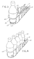
- the pusher mechanism 14 is shown merchandising one product 70 in the merchandise system 10.
- the product is prevented from tipping out of the tray by the product-retaining member 44.
- the product 70 may be any product to be merchandised including the depicted soft drink bottle.
- the product 70 sits on the pusher floor 52 and the coiled spring 30 that extends below the product. The weight of the product on the floor 52 and the positioning of the product across the spring 30 prevent the paddle 50 from tipping in the tray 12.
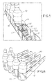
- the pusher mechanism 14 is shown merchandising multiple products 70 in the merchandise system 10.
- the product next to the pusher paddle 50 sits on the pusher floor 52 and the coiled spring 30 that extends below the product.
- the other products will sit on the coiled spring 30 that will extend below these products.
- the adaptor 180 may be positioned in the system in which case the product may sit on the ribs 182 of the adaptor as opposed to the coiled spring. Again, the weight of the product on the pusher floor 52 and the positioning of the products across the spring 30 prevent the paddle 50 from tipping in the tray.
- the pusher mechanism 14 In use, as one product is removed from the front of the tray near the product-retaining member 44, the pusher mechanism 14 (through the urging of the coiled spring 30) will push the remaining product forward in the tray 12 until the forward-most product contacts the product-retaining member 44. As additional products are removed, the pusher mechanism 14 will continue to push the remaining product toward the product-retaining member 44.
- a rear view of the pusher mechanism 14 shows the pusher mechanism 14 merchandising multiple products 70 in the merchandise system 10.
- the product next to the pusher paddle 50 sits on the pusher floor 52 and the coiled spring 30 that extends below the product.
- the other products will sit on the coiled spring that will extend below these products.
- the adaptor 180 may be positioned in the system in which case the product may sit on the ribs 182 of the adaptor as opposed to the coiled spring.
- the coiled end 57 of the spring 30 will urge the pusher paddle 50 of the pusher mechanism 14 forward in the tray 12 until the forward-most product contacts the product-retaining member 44.
- the coiled end 57 may be positioned between two support members 58. The support members will retain the coiled spring between these members.
- the pusher floor 52 may also extend below the support members 58.
- multiple trays 12 may be formed into a single multi-tray assembly 80.
- the multi-trays may have a common floor with dividers 18 extending upwardly from the floor to create the multiple trays or rows.
- the product-retaining member 44 may be a solid member that extends between two dividers, as discussed above.
- One or more of the multi-tray assemblies 80 may be coupled or joined together in a side-by-side manner using any known technique, including clips, dovetailing, fasteners, or the like. With this configuration, numerous rows of product can be provided for the merchandising of numerous products.
- the trackless pusher mechanism 14 may be used with gravity-fed systems, that is, systems having trays or product channels that are mounted on an incline to permit gravity to assist with the merchandising of the product.
- the trackless pusher mechanism 14 may be used with systems that are mounted in a non-inclined or in a horizontal manner where gravity will provide little or no assistance with the merchandising of the product.
- the trackless pusher mechanism 14 may also be used to push various shaped products.
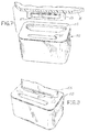
- Figure 7 depicts an example tip 60 for the end 29 of a coiled spring 30 that may be used with the merchandise system 10.
- the tip 60 defines an aperture 61 for receiving the end 29 of the coiled spring and an aperture 63 for mounting to the surface 16 of the tray.
- extending beneath the surface 16 may be a tongue or mounting member 65 that may be configured to mate with the aperture 63 and to snap-fit the tip 60 onto the tongue 65 and thus to the surface 16.
- the tip 60 of Figure 7 is shown being mounted to the tongue or mounting member 65.
- the tongue 65 may include an elongated outwardly extending rib 67 that is used to snap-fit the tip 60 onto the tongue 65. It is to be appreciated that other techniques may be used to mount the tip 60 to the surface 16 and that the depicted technique is merely an example of one such technique.
- the tip 60 is shown fully mounted in a snap-fit manner to the surface 16, and more specifically to the end portion 24 of the surface 16 of the tray 12. Also depicted is the mounting of the end 29 of the coiled spring 30 to the aperture 61 of the tip 60. As shown in Figure 9 , the end 29 of the coiled spring may be inserted into the aperture 61. The aperture 61 is configured to receive the end 29 of the coiled spring and hold the end 29 in position, and to also permit the removal of the end 29 of the coiled spring from the aperture 61 in those circumstances where it is desirable to disconnect the coiled spring from the tip to permit the removal of the pusher mechanism 14 from the system.
- a mounting member 130 may be used to mount the end 29 of the coiled spring to the floor 131 of the system.
- the mounting member 130 may be snap-fit to or otherwise mounted on the floor 131 and between the glide rails 132. The mounting member will thus hold the end of the coiled spring in position and to the floor of the system.
- the mounting member 130 may include one or more legs 136 on one or more sides of the member 130.
- the legs may be configured to snap-fit to the underside of the rails 132 to thereby hold the mounting member 130 to the floor of the system.
- the legs 136 may include legs ends 137 defining an L-shape or angled surfaces that are configured to contact the underside of the rail 132 and prevent the mounting member 130 from being lifted up from the floor, except by the intentional flexing of the legs out from the underside of the rail 132.
- the legs 136 may contact the connecting ribs 134 which will prevent slidable movement of the mounting member 130 relative to the floor.
- the mounting member 130 is shown being mounted to the floor of the system and more specifically to the rails.
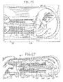
- Figure 27 illustrates that the mounting member 130 remains in position as the pusher paddle 141 is pulled away from the front of the system.
- the mounting member 130 may be connected to this type of system floor 131 using other techniques. For example, a separate mounting clip, one or more fasteners, adhesives, or other techniques may be used to secure the mounting member 130 to the floor 131.
- the mounting member 130 may also include an aperture or opening or slot 138 that will receive the end 29 of the spring.
- the spring may be mounted using any of the techniques described herein, or other techniques. The configuration of the aperture 138 and mounting member 130 will hold the spring in position on the mounting member 130, similar to the technique described above.
- the mounting member 130 may also include glide ribs 139 on a top surface that allow product placed thereon to slide more easily across the mounting member after the mounting member is installed to the floor of the system.
- the mounting member 130 may also include an elongated flat body 140 that extends forward of the location of the legs 136 to provide stability to the mounting member 130 after it is mounted to the floor of the system.
- the pusher paddle or pusher mechanism 141 may include a pusher face 143 configured to match the shape of the product against which it pushes. As illustrated, the pusher face 143 may be curve shaped to match the shape of a bottle or other cylindrical object.
- the pusher paddle 141 may also include a pusher floor 145 similar to the pusher floor configurations described above.
- the pusher floor 145 may further include a spring sleeve 147 that receives the coiled spring 30 to shield and protect the spring.
- the spring sleeve 147 may extend partly or fully across the pusher floor 145 and in the direction of the spring 30.
- the spring sleeve 147 may have a relatively short height and a flat surface 149 to permit product to sit thereon without significant tipping or leaning of the product.
- the pusher paddle 141 may be positioned on top of the floor 131 to glide on top of the surface, as described above.
- the pusher paddle may be positioned between two product divider walls 153 that are joined together by a product retaining member 155. Additional product retaining members 157 may extend outwardly from the product dividers.
- FIG. 28 and 29 there is shown yet another alternative technique for mounting the end 29 of the coiled spring 30 to the merchandise display system.
- the end 29 is riveted to the tray 216.
- the trackless pusher system may be retrofitted to an existing shelf assembly 230, which may have product dividers already built in.
- the trackless pusher system may be retrofitted to an existing wire shelf assembly.
- a tray or adaptor 216 may have a glide floor 222 that may be sized to a single lane of the shelf 234 or sized to an entire shelf width.
- the glide floor 222 may include several raised ribs 224, which help to reduce friction for the products merchandised on the tray 216. It should be understood that one or more raised ribs 224 may be used with the glide floor 222.
- the glide floor 222 may be a flat, planar surface without raised ribs.
- the tray or adaptor 216 may be configured similar to the adaptor 180 of Figure 16 .
- the end 29 of coiled spring 30 may be riveted, via a rivet 229, to the front end 228 of the tray 216, or may be attached by any other attachment technique.
- the tray 216 can be retained to the shelf by any attachment technique suitable for the particular shelf.
- the tray 216 may include one or more outwardly extending fingers or snaps 220, which may engage one or more individual wires 232 of the shelf 234 to retain the tray 216 on the shelf 234.
- the fingers or snaps 220 may extend longitudinally along the length of the tray 216, or may be spaced apart along the length of the tray.
- the snaps 220 may be used to snap-fit the tray 216 to the existing wire shelf.
- the snaps 220A and 220B may define numerous configurations that permit the tray 216 to be snap fit to the shelf.
- the example depicted in Figures 28-32 allows for the placement of the trackless pusher system in an existing shelving system, such as a wire shelf system, as a low cost alternative to the entire trackless pusher assembly. It should be understood that with this example, any pusher mechanism described herein may be used.
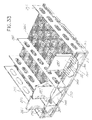
- the display management system comprises one or more pusher mechanisms 286, one or more dividers 266, one or more trays 306, and one or more retainers 250.
- the pusher mechanisms 286 can be formed of a pusher paddle 287 and a pusher floor 288. Product is placed on the pusher floor 288 and guided to the front of the display management system via the dividers 266 and the pusher paddle 287.
- the coiled spring 30 biases the pusher mechanism 286 toward the retainer 250 such that product moves to the front of the system.
- the coiled spring 30 can be mounted to the retainer 250.
- the coiled spring 30 can be mounted to a divider 266 (also shown in Figures 48 and 49 ).
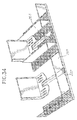
- the coiled spring 30 can be directly mounted to the retainer 250, as depicted in Figure 33 , or can be mounted to the retainer 250 via a separate adapter 252, as depicted in Figure 34 .
- the adapter 252 has a wall 254 proximate a first end 256.
- the first end 256 has a curved portion 262, which curves upwardly.
- the middle portion of the adapter 252 may be provided with a curved slot 260, which is adapted to receive a correspondingly shaped spring end (not shown).
- the coiled spring 30 at one end can be secured to the middle portion of the adapter 252.
- the curved slot 260 corresponds in shape and size of the first spring end.
- the first spring end of the coiled spring 30 can be crimped or bent to provide for additional fastening. Nevertheless, any sufficient fastening method can be used to fix the first spring end of the coiled spring 30 to the adapter 252.
- the retainer 250 has a curved slot 284 corresponding in shape and size to the curved portion 262 of the adapter 252.
- the curved slot 284 extends the length of the retainer to allow for unlimited positioning of the adapter 252 along the length of the retainer 250.
- the curved portion 262 of the adapter 252 is placed into the curved slot 284 of the retainer 250.
- the curved slot 284 secures the adapter 252 and the first spring end of the coiled spring 30 to the retainer 250 and provides for a quick and easy assembly of the display system.
- the wall 254 provides additional stability in the connection between the retainer 250 and the adapter 252. Other methods, however, can be used to secure the adapter 252 and/or the first spring end of the coiled spring 30 to the retainer 250.
- the coiled spring 30 of the pusher paddle 287 can be mounted directly to the front of the tray 306.
- the first spring end 290 of the coiled spring 30 is provided with a curved portion.
- the curved portion curves downwardly from the pusher floor 288 and is adapted to be received in a recess 316 (shown in Figure 33 ) defined by a lip 318 of the front surface of the dispensing tray 306 and the retainer 250.
- a vertically oriented surface of the retainer 250 and the lip 318 are spaced such that a gap is formed between the vertically oriented surface and a front edge of the lip 250.
- the first spring end 290 is inserted into the gap formed between the vertically oriented surface of the retainer 250 and the front edge of the lip 318 and placed into the recess 316 formed by the lip 318 of the dispensing tray 306 and the retainer 250.
- the coiled spring 30 can be directly mounted to a divider 266.
- the coiled spring 30 can be mounted perpendicular to the pusher floor 288 such that the axis, about which the coiled spring 30 is coiled, is perpendicular to the pusher floor 288. This orientation has the benefit of preventing the pusher paddle from tipping back.
- the first spring end 290 can be provided with an angled portion 292 and a tip portion 296.
- the angled portion 292 can be bent perpendicular to the coiled spring body 294.
- the divider can be provided with a slot 298, which is adapted to receive the tip portion 296 of the first spring end 290.
- the tip portion 296 is inserted into the slot 298. Once the tip portion 296 is fully inserted into the slot 298, the angled portion 292 engages the slot 298 so as to secure the first spring end 290 to the divider 266.
- the pusher paddle 287 can be formed flat to accommodate correspondingly shaped product.
- the pusher paddle 286 can have a curved first end and a flat second end. This serves to accommodate a variety of cylindrical products having a variety of different sized diameters and to facilitate the operation of the pusher mechanism 286.
- the product in the pusher mechanism 286 and the curved first end together force the pusher mechanism against the divider 266, such that the coil spring 30 remains flat against the divider 266 holding the first spring end 290, while in tension or in operation. This allows for a smoother operation of the pusher mechanism and ensures that the product is properly dispensed as users remove the product from the system.
- the distance between the dividers 266 can be adjusted to accommodate different sized containers.
- the dividers 266 can be provided with connecting portions 272.
- the connecting portions 272 can be provided with a first elongated angled surface 268 and a second elongated angled surface 270. Additionally, the connecting portions 272 can be provided with a plurality of projections 274.
- the rails can be formed of teeth 278 having face surfaces 280 and flank surfaces 282.
- the connecting portions 272 When assembled, as depicted in Figure 41C , the connecting portions 272 are received between the teeth 278 of the rails. Additionally, the elongated angled surfaces 268 and 270 and the projections 274 are wedged between the teeth 278. Also as shown in Figure 41C , the elongated angled surfaces 268 and 270 engage the face surfaces 280, and the projections 274 engage the lower surfaces of the teeth 278. Flank surfaces 282 contact the connecting portion 272.
- the trays 306 are provided with dovetail connections.
- a first side 308 of the trays 306 is provided with tongues 312 adapted to fit within grooves 314 located on a second side 310 of the trays 306.
- the grooves 314 are aligned with tongues 312 such that the tongues 312 are firmly secured within the grooves 314.
- the trays 306 are configured to receive the retainer 250 at a front end.
- the retainer can be provided with rectangular holes 300, and the retainer is provided with correspondingly shaped and sized projections 302. To secure the retainer 250 to the tray 306, the projections 302 fit into holes 300 to lock the retainer into place on the tray 306.
- the product management display system 400 can be arranged such that trays 402, 404 can be stacked on top of one another.
- This example can consist generally of a first tray 402, a second tray 404, a first spacer 406, and a second spacer 408.
- the trays 402, 404 are each arranged to house product to be dispensed.
- the first tray 402 and the second tray 404 can be each provided with a clear retainer 410, a pusher mechanism 412, first and second guiding walls, and a coil spring 414.
- the pusher mechanism 414 is arranged in a similar fashion as the examples discussed above, such that it slides product along the surface of the trays 402, 404, while product is removed. Additionally, any of the alternative arrangements of the pusher mechanism discussed above may be implemented in a stackable tray arrangement.
- the stackable product management display system can be provided with a dovetail connection or any other suitable connection, such as a snap-fit connection, screw-thread connection, or a rivet connection.
- the first and second trays are provided with detents 416 for assembling the first and second spacers 406, 408 to the first and second trays 402, 404.
- Each of the first and second trays 402, 404 can be provided with sockets 418 on their respective outside surfaces for receiving the correspondingly shaped detents 416 located on the first and second spacers 406, 408.
- the detents 416 located on the first and second spacers 406, 408 are placed into the correspondingly shaped sockets 418 on the outside surfaces of the first and second trays 402, 404 in a locking arrangement. This provides for a stackable arrangement that can be implemented in conjunction with any of the examples discussed above.
- a pusher paddle 500 may be mounted directly to a shelf 508 and held to the shelf by the end of the coiled spring 504. The pusher paddle 500 will slide along and on top of the surface of the shelf.
- One or more dividers 502 that define a T-shaped configuration may be positioned next to the pusher paddle 500.
- the base of the divider 502 may be positioned on the shelf such that the base is located underneath the pusher paddle 500. With this configuration, the pusher paddle 500 may slide along the base of the divider. If the dividers 502 are positioned sufficiently far away from the paddle 500, the paddle 500 will slide directly on the surface of the shelf 508.
- the dividers 502 may define numerous configurations including those described herein and may be secured to the shelf using any known technique, including push pins, rivets, fasteners, adhesives and the like.
- the end 510 of the coiled spring 504 is positioned within a hole or aperture 506 located on the shelf 508.
- the end 510 may define a spring tip that may further define any suitable configuration that permits the spring end to pass into the hole 506 and remain secured to the hole.
- the spring tip of end 510 may define a hook-shaped configuration that permits the end 510 to wrap around the edges of the hole 506.
- the spring tip may define one or more catches that hook onto the edges of the hole 506. Still other spring tip configurations are possible.
- a fastener 512 may be used to further secure the spring 504 to the shelf 508 .
- This fastener 512 will provide a second spaced-apart anchoring point for the spring that will hold the spring in the desired alignment during the full operation of the spring 504 as the paddle 500 moves back and forth on the shelf 508. It will be appreciated that depending on the shelf type and the number and spacing of existing holes on the shelf, even more anchoring points are possible.
- FIG. 55 there is depicted an example mounting technique for mounting the spring 504 of the paddle 500 onto a shelf.
- the end 510 of the spring 504 is inserted into the hole 506 on the shelf.
- the end 510 may define a spring tip as described herein to hold the end 510 to the edges of the hole 506.
- the spring 504 which in this example includes a rivet or stud 514, is lowered onto the shelf such that the rivet or stud 514 fits within another hole 506 located on the shelf. This rivet or stud provides another anchoring point for the spring.
- the spring 504 may define an aperture 516 for receiving yet another rivet or stud 518 to even further secure the spring 504 to the shelf.
- the spring 504 will be secured to the shelf, and thus the paddle will be secured to the shelf.
- the spring will retain the desired alignment during the full operation of the spring as the paddle moves back and forth on the shelf. It should be understood that other anchoring techniques are possible to secure the end of the spring 504 to the shelf, including any of the technique described herein, or any combination of the techniques described herein. It should be appreciated that if a shelf does not have preexisting holes that could be used to anchor the spring 504, one or more holes could be drilled into the shelf at the desired locations.
- a trackless pusher paddle may be retrofitted directly onto existing store shelves with very minimal effort or extra mounting pieces. Additionally, this example is easily removable to permit the repositioning of the pusher paddle at any location on the shelf to accommodate any size and type of product being merchandised on the shelf. It is to be appreciated that any of the pusher paddles described herein may be mounted directly to the shelf using the techniques described herein, or by using any combination of the techniques described herein.
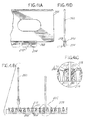
- a tray 12 in another example, depicted in Figures 58-60 , includes a front rounded portion 669. As illustrated in Figure 58 , the tray 12 also includes a forward lip 670 that is located adjacent the front of the front rounded portion 669. The forward lip 670 can be rounded and can extend perpendicularly in an upward direction from the tray 12. The forward lip can have different heights and in an example has a height of 0.5 inches from the tray 12. The forward lip includes a raised edge or wall portion 671 at each lateral end of the forward lip. The wall portions serve to close off the side portions of the caption pocket that is described later.
- the tray also can include a shelf 672 that is located immediately adjacent and in a frontward direction of the forward lip 670.
- the shelf 672 can be curved and can match the curvature of the forward lip 670.
- the shelf 672 includes a horizontal surface 674.
- the shelf 672 also includes protrusions 676 that are perpendicular to the horizontal surface 674 of the shelf 672.
- the shelf 672 and the forward lip 670 add strength to the front portion of the pusher tray.
- the horizontal surface 674 of the shelf 672 serves to close off the bottom portion of the caption pocket that is described later.
- a front wall 100 includes a top wall 680 and a bottom wall 682.
- the top wall and the bottom wall are connected by two side legs 684.
- the top wall 680 and the bottom wall 682 are curved.
- An aperture 686 is defined by the top wall 680, bottom wall 682 and side legs 684. This aperture can be sized such that a product P will not fit through the aperture.
- the top wall also can contain a contour from the top 688 of the top wall to the bottom 690 of the top wall. This contour assists in limiting or preventing scratches to the top wall. The contour also increases the strength of the top wall.
- the bottom wall includes a side wall 708 that in operation is adjacent to and may be in contact with protrusion 676.
- the side legs include notches 698 at the bottom portion of the side legs 684.
- the notches assist in allowing the hooks 694 to be inserted into apertures 696.
- the front wall can be constructed of clear material which will not obstruct the view of product P being merchandised in trays 12.
- a graphic pocket 692 is defined by (a) the bottom wall 682 of the front wall 100, (b) the curved portion of lip 670, (c) wall portions 671 at the lateral ends of lip 670 and (d) the horizontal surface 674 of shelf 672.
- This graphic pocket is sized to contain a graphic strip or other advertising. Once the graphic strip is placed in the pocket 692, it is protected from all sides other than the top.
- the front wall further comprises two hooks 694. These hooks are configured to fit within with apertures 696 of tray 12.
- the front wall first is rotated in the direction of the arrow "A" as depicted in figure 101 with the hooks 694 not in engagement with the apertures 696.
- the hooks 694 are then initially inserted into the apertures 696 while the hooks 694 are at an angle to the apertures.
- the front wall is then rotated in the direction of the arrow "B" until the front wall comes to the position shown in figure 102-B.
- the hooks 694 are thereby mounted to the tray 12.
- the rear edge 700 of side legs 684 is adjacent to the front edge 702 of the divider 18.
- the rear edge 700 of side legs 684 may be in contact with the front edge 702 of divider 18.
- Figures 59A-C disclose different mounting states of the front wall 100 and a graphic caption 706.
- Figure 59A discloses the front wall 100 not mounted with the tray 12. Instead, front wall 100 is shown elevated above tray 12.
- Graphic caption 706 also is shown in an unmounted state.
- Figure 59B discloses front wall 100 mounted with tray 12. In Figure 59B graphic caption 706 is unmounted. The downward arrows in Figure 59B show the direction graphic caption 706 will move in to mount with the graphic pocket 692.
- Figure 59C discloses the graphic caption 706 mounted in graphic pocket 692.
- the graphics caption 706 can form a continuous or near-continuous strip of graphics advertising. Trays 12 can be formed individually and connected together, such as through dovetail connections. In an example, multiple trays can be formed as a unit to create a single unit for merchandising numerous rows of products.
- Figure 60 discloses several front walls 100 mounted with several trays 12. The near-continuous nature of the graphics advertising from the graphics caption 706 is seen in Figure 60 . In addition, Figure 60 discloses product P being maintained on trays 12 and constrained by front walls 100.
- a pusher mechanism for a merchandise display is configured to be placed into a tray preloaded with packages.
- the pusher mechanism includes a first spring configured to bias the pusher mechanism and a pusher paddle.
- the pusher paddle includes a guide panel defining a guide panel plane, a first folding panel defining a first folding panel plane, a second folding panel defining a second folding panel plane.
- the pusher mechanism includes a second spring configured to bias the first folding panel and the second folding panel such that the first folding panel plane and the second folding panel plane are parallel to the guide panel plane.
- the first folding panel and the second folding panel are configured to pivot on the pusher mechanism.
- the first folding panel and the second folding panel are configured to move in a rearward direction of the pusher mechanism.
- the first folding panel and the second folding panel pivot on a first living hinge and a second living hinge.
- the first folding panel and the second folding panel each include a pair of guide members configured to guide a first end and a second end of the second spring.
- the pusher mechanism can include a post for receiving the second spring, and a notch configured to receive a plate insert.
- the plate insert is configured to be secured to a shelf configured to receive the packages.
- the pusher mechanism can be part of a merchandise display system which includes a tray configured to receive packages and a perforated portion configured to provide an opening.
- the first folding panel and the second folding panel of the pusher mechanism permit the pusher mechanism to be placed into the opening in the tray.
- the first folding panel, the second folding panel and the guide panel form the pusher paddle and can be configured to provide for a surface for biasing the packages in the tray.
- the tray comprises a vertically extending wall and a horizontally extending wall, and the opening is located on the vertically extending wall.
- the horizontally extending wall can have a second opening configured to receive a bottom plate of the pusher mechanism.
- a method for displaying merchandise comprises: providing a tray configured to receive packages, the tray having a perforated portion configured to provide an opening, and providing a pusher mechanism.
- the pusher mechanism comprises a first spring configured to bias the pusher mechanism, a pusher paddle comprising a guide panel defining a guide panel plane, a first folding panel defining a first folding panel plane, a second folding panel defining a second folding panel plane, and a second spring configured to bias the first folding panel and the second folding panel such that the first folding panel plane and the second folding panel plane are parallel to the guide panel plane.
- the first folding panel and the second folding panel are configured to pivot on the pusher mechanism.
- the method further comprises configuring the first folding panel and the second folding panel of the pusher mechanism to pivot relative to the guide panel to permit the pusher mechanism to be placed into the opening in the tray and the first folding panel, and configuring the second folding panel and the guide panel forming the pusher paddle to provide for a surface for biasing the packages.
- the method further comprises configuring the first folding panel and the second folding panel to move in a rearward direction of the pusher mechanism, configuring the first folding panel and the second folding panel to pivot on a first living hinge and a second living hinge, and providing the first folding panel and the second folding panel with a pair of guide members configured to guide a first end and a second end of the second spring.
- the method further comprises providing a post for receiving the second spring.
- the tray further comprises a vertically extending wall and a horizontally extending wall, and the opening is located on the vertically extending wall.
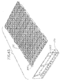
- the pusher mechanism 814 is formed with folding panels 815a, 815b for placing the pusher mechanism 814 into a box 811 and tray assembly 812.
- the tray assembly 812 operates as a guiding mechanism for the packages 870.
- the packages 870 can be preloaded and shipped in a box 811, which is configured to open at a bottom and end portion to permit the pusher mechanism 814 to be placed in contact with the packages 870 and the tray assembly 812 initially formed as part of the box 811 can be used to guide the packages 870 toward the front portion of the tray assembly and the shelf. In this way, the packages 870 are always pushed all the way to the front of the shelf, gives a neater appearance to the consumer, and is easier to use for the consumer.
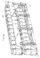
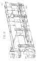
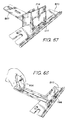
- Figure 61 shows a perspective view of the pusher mechanism 814.
- Figure 62 shows a top view and Figure 63 shows a rear view.
- the pusher mechanism 814 comprises a first coil spring 830, a guide panel 854, two folding panels 815a, 815b, and a coil spring housing 858. Together the guide panel 854 and the two folding panels 815a, 815b form a pushing surface for pushing the packages 870 toward the front of a shelf.
- the first coil spring 830 is configured to coil up within the coil spring housing 858 of the pusher mechanism 814.
- the pusher mechanism 814 can be provided with a first coil spring 830 locking mechanism 845 for locking a first end of pusher mechanism guide 847 and pusher mechanism 814 into place on the pusher mechanism guide 847.
- the pusher mechanism guide 847 can be provided with a notch 847a for aligning the pusher mechanism 814 to an insert or front rail 849 (depicted in Figures 67 and 68 ) extending perpendicular to the pusher mechanism guide 847.
- the front rail 849 can be secured to a shelf using any known fastening method, such as fasteners, adhesives, etc.
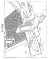
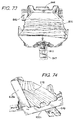
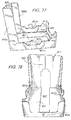
- the folding panels 815a, 815b provide a collapsible pusher mechanism 814. As shown in Figures 70 and 72 , this feature permits the pusher mechanism 814 to occupy a smaller space initially through the opening 823 of the box or tray assembly 812 during the assembly of the pusher mechanism 814 to the tray 812 and the placement of the tray 812 and packages 870 on shelves for consumers. As shown in Figure 63 , the pusher mechanism 814 is provided with two vertical living hinges 807a, 807b that interconnect the guide panel 854 to the two folding panels 815a, 815b. The vertical living hinges 807a, 807b provide for the pivoting of the folding panels 815a, 815b on the pusher mechanism 814.
- the pusher mechanism 854 also includes a second coil spring 813 which mounts on a second coil spring post 821.
- the second coil spring 813 biases the folding panels 815a, 815b such that each plane defined by the folding panels 815a, 815b is biased parallel with a plane defined by the guide panel 854.
- each folding panels 815a, 815b include a pair of elongated guides 819 that provide guides for each of the ends 813a, 813b of the second coil spring 813.
- the guides assist the second coil spring 813 in biasing the folding panels 815a, 815b in a direction parallel with the guide panel 854.
- the folding panels 815a, 815b permit the pusher mechanism 814 to be placed into a vertically extending opening 823 on a rear portion of the tray 812 containing the packages 870.
- the box provides a tray 812 for dispensing the packages 870.
- the pusher mechanism 814 is placed into contact with the packages 870 and biases the packages 870 toward the front of the tray 812 for the consumer to grab off of the shelf (not shown).
- the opening 823 in the box 812 provided for the pusher mechanism can be formed smaller in size. Due to the smaller opening, the box structure 811 or tray assembly 812 is not compromised structurally as much because it still has a sufficient structure for loading and dispensing the packages 870 on the shelf.
- the pusher mechanism 814 can fold up along the living hinges 807a, 807b to occupy a smaller opening 823 formed by a perforated portion 825 in the box 812.
- the second coil spring 813 then biases the folding panels parallel with the guide panel 854. This provides for a larger pushing surface area to bias the packages 870 toward the fixed panel 844 to obtain the proper amount of force on the packages 870 to force the packages toward the front of the tray 812.
- the box 811 can be provided with a top section (not shown).
- the packages 870 can then be placed into the box 811 and the top section can then be removed exposing the packages 870 in the tray assembly 812.
- the tray assembly 812 can be formed by a vertically extending wall 835 and a horizontally extending wall 837.
- the vertically extending wall 835 can be provided with guide portions 835a, 835b and the horizontally extending wall 837 can also be provided with guide portions 837a, 837b.
- the guide portions 835a, 835b, 837a, 837b assist in guiding the packages 870 in the tray assembly 812.
- the perforated portion 825 provides a portion of the tray 812 for the vertically extending opening 823 located on the vertically extending wall 835 and a slot opening 827 located on the horizontally extending wall 837 along the bottom portion of the tray 812.
- the vertically extending opening 823 provides a location for the pusher mechanism 814 to be placed into contact with the packages 870 such that the pusher mechanism 814 can bias the packages 870 toward the fixed panel 844, which can be located toward the front of a shelf displaying the packages 870.
- the slot opening 827 along the bottom portion of the tray 812 provides an elongated slot for the pusher mechanism 814 bottom plate 833 to travel along the pusher mechanism guide 847.
- the perforated portion 825 can be removed from the tray 812. Additionally, the perforated portion 825 and the vertically extending wall 835 can be provided with a predetermined opening 823b, which provides a grasping portion on the perforated portion 825 for the user to remove the perforated portion 825 from the box 812.
- the packages 807 are loaded into the box 811 having a top portion (not shown).
- the user then removes the top portion of the box 811 to form the tray 812.
- the perforated portion 825 can then be removed from the tray 812 along the vertically extending wall 835 and the horizontally extending wall 837 to form vertically extending opening 823 and slot opening 827.
- the user can then place the pusher mechanism 814 into contact with the packages 870.
- the notch 847a of the pusher mechanism guide 847 can then be placed into contact with the front rail 849, which can be fixed on a shelf. Once the consumer pulls one of the packages 870 off of the shelf, the remaining packages 870 are biased toward the fixed panel 844 and the packages 870 remain upright and appear neat to the consumer.
- a merchandise display system comprises a first pusher mechanism having a first pusher paddle, a first spring, and a first guide rail.
- the first pusher mechanism is configured to be biased by the first spring along a plane defined by the first guide rail.
- a second pusher mechanism includes a second pusher paddle, a second spring, and a second guide rail.
- the second pusher mechanism is configured to be biased by the second spring along a plane defined by the second guide rail.
- the first guide rail and the second guide rail are configured to mount on a horizontally orientated shelf. Each plane of the first guide rail and the second guide rail extends perpendicular to a plane defined by the shelf.
- the first pusher mechanism and the second pusher mechanism extend a predetermined distance from the shelf.
- the merchandise display assembly 900 can include two pusher mechanisms 914 that push the products from both sides.
- the merchandise display assembly 900 includes a front rail 944 and two side dividers 918.
- the two side dividers 918 provide a guide and support for the pusher mechanisms 914.
- the pusher mechanisms 914 can come preassembled to the two side dividers 918 via a coil spring (not shown).
- the coil springs can be fixed to a front end of the dividers 918 such that the coil spring biases the pusher mechanisms 914 toward the front of the tray 912.
- the side dividers 918 can be fixed to the shelf 970 using removable fasteners, rivets, adhesive, snap-fit, or any other known suitable connections.
- the pusher mechanisms 914 can include a coil spring to bias the pusher mechanisms toward the front rail 944.
- the pusher mechanisms 914 can also include a paddle 950 which contacts the products 970.
- the pusher mechanisms 914 can be provided with a hinge (not shown) such that the paddles 950 can rotate on an axis parallel to a plane defined by the side dividers 918.
- the pusher mechanisms 914 can also be provided with rotating extensions (not shown). Both the hinges and the rotating extensions provide for paddles 950 that can be moved out of the way of the products 970 while configuring the pusher mechanisms on a shelf 908.
- the products 970 can be prearranged on tray 912, which can be placed onto a shelf 908.
- the side dividers 918 can then be adjusted on the shelf 908 according to the size of the tray 912.
- the paddle 950 can then be placed into contact with the last row of products 970.
- the pusher mechanisms 914 biases the products 970 toward the front of the tray 970.
- a merchandise display system comprises a plurality of pusher mechanisms each including a guide, a spring, and a pusher paddle.
- the guides of the pusher mechanisms include a pair of guide openings.
- the merchandise display system also has a pair of adjustable side portions.
- the adjustable side portions include alignment tubes providing for an adjustable length between the adjustable side portions. The alignment tubes are received in the pair of guide openings of the guides of the pusher mechanisms.
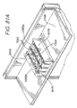
- FIG. 81A and 81B The example shown in Figures 81A and 81B is similar to the example depicted above in Figures 80A and 80B .
- the pusher guides or tracks 1018 are provided across and over the top of the products 1070.
- the pusher tracks 1018 provide a guide and support for the pusher mechanisms 1014.
- the merchandise display assembly 1000 can include multiple pusher mechanisms 1014 having multiple paddles 1050 and multiple paddle extensions 1053 that push the products 1070 across and over the top of the merchandise display.
- the merchandise display assembly 1000 can include two extendable side portions 1019.
- the two extendable side portions 1019 can be provided with a pair of male alignment tubes 1055a and a pair of female alignment tubes 1055b, which provide for a variable length between the side portions 1019.
- the male alignment tubes 1055a can be received by the female alignment tubes 1005b to provide for a sliding adjustment between the extendable side portions 1019.
- Each of the pusher tracks 1018 can be provided with guide openings 1057 for receiving the alignment tubes 1055a, 1055b.
- the alignment tubes 1055a, 1055b can be secured to the guide openings 1057 by any suitable fastening method to fix the position of the side portions 1019 with respect to each other.
- the side portions 1019 can be secured to the shelf 1008 by any known suitable fastening method.
- the pusher mechanisms 1014 can come preassembled to the pusher tracks 1018 via a coil spring (not shown).
- the coil springs can be fixed to a front end of the pusher tracks 1018 such that the coil spring biases the pusher mechanisms 1014 toward the front of the tray 1012.
- the pusher mechanisms 1014 can be secured to the paddle extensions 1053 using any known fastening method.
- the pusher mechanisms 1014 can include a coil spring to bias the pusher mechanisms 1014 toward the front of the tray 1012.
- the paddle extensions 1053 are configured to contact the products 1070 and to push the products 1070 toward the front of the tray 1012.
- the pusher mechanisms 1014 can be provided with hinges such that the paddles 1050 and the paddle extensions 1053 can rotate on an axis parallel to the male and female alignment tubes 1055a, 1055b. The hinges provide for paddles 1050 and paddle extensions 1053 that can be moved out of the way of the products 1070 while configuring the pusher mechanisms on a shelf 1008.
- the products 1070 can be prearranged on the tray 1012, which can be placed onto a shelf 1008.
- the side portions 1019 can then be adjusted on the shelf 1008 according to the size of the tray 1012, and the side portions 1019 can be fixed with respect to one another according to the size of the tray 1012.
- the paddle 1050 can then be placed into contact with last row of products 1070.
- the pusher mechanisms 1050 biases the remaining products 1070 toward the front of the tray 1070.
- a merchandise display system in another example described in relation to Figures 82A-82D , includes a pusher mechanism, a front rail, and a rear rail.
- the pusher mechanism can include a pusher paddle, a pusher guide, and a spring.
- the pusher guide is configured to slide on the rear rail and is configured to extend over the products, and the pusher paddle is configured to bias products toward the front rail.
- the example shown in Figures 82A-82D is similar to the example depicted in Figures 80A and 80B .
- the pusher guide 1118 extends over the top of the products 1170.
- the merchandise display assembly 1100 can include a pusher mechanism 1114 that pushes the products from the top of the assembly 1100 or shelf 1108.
- the merchandise display assembly 1100 includes a front rail 1144a and a back rail 1144b.
- the pusher guide 1118 provides a guide and support for the pusher mechanism 1114.
- the pusher mechanism 1114 can come preassembled to the pusher guide 1118 via a coil spring (not shown).
- the coil spring can be fixed to a front end of the pusher guide such that the coil spring biases the pusher mechanism 1114 toward the front rail 1144a.
- the pusher guide 1118 is configured to slide along the back rail 1144b to adjust to location of the products 1170 on the shelf 1108.
- the pusher mechanism 1114 can include a coil spring to bias the pusher mechanism 1114 toward the front rail 1144a.
- the pusher mechanism 1114 can also include a paddle 1150 which contacts the products 1170.
- the pusher mechanism 1114 can be provided with a hinge such that the paddle 1150 can rotate on an axis parallel to the back rail 1144b. The hinge provides for a paddle 1150 that can be moved out of the way of the products 1170 while configuring the pusher mechanisms on a shelf 1108.
- Figures 82C and 82D depict an alternate back rail 1144b that can be used in conjunction with the pusher mechanism 1118. In this arrangement the back rail 1144b can be provided with a flange configured to rest on the shelf 1108.
- the products can be prearranged on tray 1112, which can be placed onto a shelf 1108.
- the pusher mechanism 1118 can then be located on the shelf 1108 according to the size and orientation of the tray 1112 on the shelf.
- the paddle 1150 can then be placed into contact with last row of products 1170.
- the pusher mechanism 1114 biases the remaining products 1170 toward the front of the tray 1112.
Landscapes
- Freezers Or Refrigerated Showcases (AREA)
- Display Racks (AREA)
Description
- The invention relates generally to a shelf assembly for use in merchandising product and more particularly to a shelf assembly having improved mechanisms for displaying and pushing product on the shelves.
- It is known that retail and wholesale stores, such as convenience stores, drug stores, grocery stores, discount stores, and the like, require a large amount of shelving both to store product and to display the product to consumers. In displaying product, it is desirable for the product on the shelves to be situated toward the front of the shelf so that the product is visible and accessible to consumers. In the case of coolers or refrigerators that are used to store and display such products as soft drinks, energy drinks, bottled water, and other bottled or canned beverages, it is desirable for these products to also be situated toward the front of the shelf and visible and accessible to the consumers.
- To accomplish this placement of product, known systems may include inclined trays or floors that through gravity will cause the product to move toward the front of the shelf. Many of these systems include floors or shelves made of a plastic material such as polypropylene that due its low coefficient of friction permit the product to easily slide along the inclined floor or surface. However, over time, these surfaces can become obstructed with debris or sticky substances that inhibit the product from properly sliding, sometimes causing several products to tip over thus blocking additional product from moving to the front of the shelf.
- Other systems include the use of a pusher system to push the product toward the front of the shelf as the product at the front of the shelf is removed. The known pusher systems are typically mounted to a track and include a pusher paddle and a coiled spring to urge the product forward. Occasionally, as the system is used, and over time, the track becomes obstructed with dirt or sticky materials that hinder the proper operation of the pusher system in the track. In addition, depending on the size, shape and weight of the product to be merchandised, the known pusher paddles may occasionally tip or bend backwards, thereby causing a binding of the pusher mechanism in the track. In those situations, the pusher mechanism may not properly push product toward the front of the shelf.
-
US 2007/194037 A1 discloses a spring alignment mechanism that utilizes a guide inserted into a display carton below merchandise items. A spring-driven rear pull member travels on the guide so that as items are removed from the carton, remaining items are pulled forward. Merchandise items with rounded edges may rest on the directly on the carton, so that the guide may be inserted beneath the items. Other items may be supported on cardboard support ribs built into the bottom of the carton or provide on a carton insert.US 2012/234851 A1 discloses a product dispensing system including a container that defines an internal volume and an access opening into the internal volume, at least one product received in the internal volume and a biasing assembly extendable into the internal volume to urge the product toward the access opening, wherein the container is engaged with the biasing assembly when the biasing assembly extends into the internal volume.US 2012/118840 A1 discloses an apparatus for storing and displaying packages. A self-adjusting shelf comprises a sled coupled to a track, and at least two product supports located in a plane above the track. The product supports are aligned substantially parallel to the track and are coupled to the track. Packages rest upon the product supports. The sled slides along the length of the track. The sled urges, via either gravity or a biasing device, the sled forward against downstream packages. Thus, when one package is removed, the sled forces the remaining packages to the front of the shelf. - One embodiment is directed at improving upon existing merchandising systems by providing a trackless pusher system that works with gravity-fed merchandise systems (i.e., inclined shelves or trays) and non-gravity-fed merchandise systems.
- According to a first aspect there is provided a pusher mechanism for a merchandise display system as claimed in
claim 1. - According to a second aspect there is provided a merchandise display system as claimed in claim 8.
- According to a third aspect there is provided a method of displaying merchandise as claimed in claim 15.
-
-
Figure 1 depicts an isometric exploded view of an example of a product management display system, not according to the invention. -
Figure 2 depicts an isometric view of an example pusher mechanism mounted to an example tray or product channel, not according to the invention. -
Figure 3 depicts another isometric view of the system ofFigure 2 with product placed in the system. -
Figure 4 depicts another isometric view of the system ofFigure 2 with multiple products placed in the system. -
Figure 5 depicts an isometric rear view of the system ofFigure 4 . -
Figure 6 depicts an alternative example of the tray or product channel, not according to the invention. -
Figure 7 depicts an example tip for an end of a coiled spring that may be used with the product management display system, not according to the invention. -
Figure 8 depicts the tip ofFigure 7 being mounted to a surface of a tray or product channel. -
Figure 9 depicts the tip ofFigure 7 being mounted to an end of a coiled spring. -
Figure 10 depicts the tip ofFigure 7 mounted to an end of a coiled spring. -
Figure 11 depicts an isometric view of an alternative example of a product management display system, not according to the invention. -
Figure 12 depicts another isometric view of the system ofFigure 11 . -
Figure 13 depicts a front view of the system ofFigure 11 . -
Figure 14 depicts a top view of the system ofFigure 11 . -
Figure 15 depicts a rear view of the system ofFigure 11 . -
Figure 16 depicts an isometric view of an adaptor, not according to the invention. -
Figure 17 depicts a front view of the adaptor ofFigure 16 . -
Figure 18 depicts an example installation of the adaptor ofFigure 16 . -
Figure 19 depicts an isometric view of an installed adaptor ofFigure 16 . -
Figure 20 depicts a front view of an installed adaptor ofFigure 16 . -
Figure 21 depicts an isometric view of an alternative example of a product management display system not according to the invention. -
Figure 22 depicts an isometric bottom view of an example mounting member ofFigure 21 that may be used to mount the end of the coiled spring to the floor of the display system. -
Figure 23 depicts an isometric top view of the mounting member ofFigure 22 . -
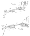
Figure 24 depicts the mounting member ofFigure 22 mounted to the end of the coiled spring with the coiled spring mounted to an example pusher paddle. -
Figure 25 depicts another view of the mounting member ofFigure 22 mounted to the end of the coiled spring with the coiled spring mounted to the pusher paddle. -
Figure 26 depicts the mounting member ofFigure 22 with attached coiled spring being mounted to the floor of the system. -
Figure 27 depicts the mounting member ofFigure 22 installed on the floor of the system. -
Figure 28 depicts an isometric view of an alternative example of a product management display system, not according to the invention. -
Figure 29 depicts a close-up isometric view of the tray of the system ofFigure 28 . -
Figure 29A depicts a cross-sectional view of the system ofFigure 28 illustrating a first securing method. -
Figure 29B depicts a cross-sectional view of the system ofFigure 28 illustrating a second securing method. -
Figure 30 depicts a close-up isometric view of the system ofFigure 28 illustrating a rivet attaching the spring to the tray. -
Figure 31 depicts an isometric view of the system ofFigure 28 being assembled in a preexisting wire shelf. -
Figure 32 depicts an isometric view of the system ofFigure 28 assembled in a preexisting wire shelf. -
Figure 33 depicts an isometric view of an example display system, not according to the invention. -
Figure 34 depicts an isometric view of an example display system, not according to the invention. -
Figure 35 depicts an isometric view of an example adapter, not according to the invention. -
Figure 36 depicts an isometric view of an example of a retainer, not according to the invention. -
Figure 37 depicts a side view of an example of the display system, not according to the invention. -
Figure 38 depicts an isometric view of an example of the display system, not according to the invention. -
Figure 39 depicts an isometric view of an example of the display system, not according to the invention. -
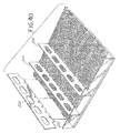
Figure 40 depicts an isometric view of an example of the display system, not according to the invention. -
Figure 41A depicts a sectional side view of an example of a divider, not according to the invention. -
Figure 41B depicts a front view of an example of the display system, not according to the invention. -
Figure 41C depicts a close up view of a section ofFigure 41B . -
Figure 41D depicts a front view of an example of a divider, not according to the invention. -
Figure 42 depicts an isometric view of an example of the display system, not according to the invention. -
Figure 43 depicts an isometric view of an example of the display system, not according to the invention. -
Figure 44 depicts an isometric view of an example of a product management display system, not according to the invention. -
Figure 45 depicts another isometric view of an example of a product management display system with product in the system, not according to the invention. -
Figure 46 depicts a top view of another example of a product management display system with product in the system, not according to the invention. -
Figure 47 depicts an isometric-rear view of an example of a product management display system with product in the system, not according to the invention. -
Figure 48 depicts an isometric view of an example of the pusher mechanism mounted to a divider, not according to the invention. -
Figure 49 depicts another isometric view of the divider and pusher mechanism being assembled to the product management display system, not according to the invention. -
Figure 50 depicts an isometric view of yet another example of the product management display system, not according to the invention. -
Figure 51 depicts another isometric view of the example of the product management display system ofFigure 50 without product. -
Figure 52 depicts an exploded isometric view of the example of the product management display system ofFigure 50 . -
Figure 53 depicts an isometric view of yet another example of the product management display system, not according to the invention. -
Figure 54 depicts an isometric view of an example of an attachment of the pusher spring to a shelf of the product management display system ofFigure 53 . -
Figure 55 depicts an isometric view of an example of an attachment of the pusher spring to a shelf of the product management display system ofFigure 53 . -
Figure 56 depicts an isometric view of an example of an attachment of the pusher spring to a shelf of the product management display system ofFigure 53 . -
Figure 57 depicts an isometric view of an example of an attachment of the pusher spring to a shelf of the product management display system ofFigure 53 . -
Figure 58 depicts an isometric view of an example of a product management display system and aspects thereof, not according to the invention. -
Figures 59A-C depict isometric views of examples of the product management display system ofFigure 58 , not according to the invention. -
Figure 60 depicts an isometric view of an example of the product management display system ofFigure 58 , not according to the invention. -
Figure 61 depicts an isometric view of an embodiment of a product management display system of the invention. -
Figure 62 depicts a partial top view of the embodiment shown inFigure 61 . -
Figure 63 depicts a partial rear view of the embodiment shown inFigure 61 . -
Figure 64 depicts a front view of the embodiment shown inFigure 61 . -
Figure 65 depicts another perspective view of the embodiment shown inFigure 61 . -
Figure 66 depicts another top view of the embodiment shown inFigure 61 . -
Figure 67 depicts another perspective view of the embodiment shown inFigure 61 . -
Figure 68 depicts another perspective view of the embodiment shown inFigure 61 . -
Figure 69 depicts a bottom view of a tray that can be used in conjunction with the embodiment shown inFigure 61 . -
Figure 70 depicts a side perspective view of the tray ofFigure 69 in use with the embodiment shown inFigure 61 . -
Figure 71 depicts a rear view of the tray ofFigure 69 . -
Figure 72 depicts another side perspective view of the tray ofFigure 69 in use with the embodiment shown inFigure 61 . -
Figure 73 depicts a top perspective view of the tray ofFigure 69 in use with the embodiment shown inFigure 61 . -
Figure 74 depicts another side perspective view of the tray ofFigure 69 in use with the embodiment shown inFigure 61 . -
Figure 75 depicts another top perspective view of the tray ofFigure 69 in use with the embodiment shown inFigure 61 . -
Figure 76 depicts a side perspective view of the tray ofFigure 69 . -
Figure 77 depicts another side perspective view of the tray ofFigure 69 . -
Figure 78 depicts a front perspective view of the tray ofFigure 69 . -
Figure 79 depicts a rear perspective view of the tray ofFigure 69 . -
Figure 80A depicts an isometric view of an example of a product management display system, not according to the invention. -
Figure 80B depicts an exploded isometric view of an example of a product management display system, not according to the invention. -
Figure 81A depicts an isometric view of an example of a product management display system, not according to the invention. -
Figure 81B depicts an exploded isometric view of an example of a product management display system, not according to the invention. -
Figure 82A depicts an isometric view of an example of a product management display system, not according to the invention. -
Figure 82B depicts an exploded isometric view of an example of a product management display system, not according to the invention. -
Figure 82C depicts an isometric view of an example of a product management display system, not according to the invention. -
Figure 82D depicts an exploded isometric view of an example of a product management display system, not according to the invention. - Before the invention is explained in detail, it is to be understood that the invention is limited by the scope of the appended claims. The invention is capable of being practiced or being carried out in various ways falling within the scope of the appended claims. Also, it is to be understood that the phraseology and terminology used herein are for the purpose of description of the invention but that the invention is limited by the scope of the appended claims. The use of "including" and "comprising" and variations thereof is meant to encompass the items listed thereafter as well as additional items. Further, the use of the term "mount," "mounted" or "mounting" is meant to include any technique or method of mounting, attaching, joining or coupling one part to another, whether directly or indirectly.
- Referring to the Figures wherein like numerals indicate like elements, there is depicted in
Figure 1 an isometric exploded view of anexample merchandise system 10, which includes aproduct dispensing tray 12 in which is mounted atrackless pusher mechanism 14. As described in more detail below, thepusher mechanism 14 will fit in thetray 12 and will slide along the surface of the tray without the use of tracks, rails, or guides typically used to hold a conventional pusher mechanism to the tray or floor of the tray. The pusher mechanism defines a pusher paddle and a pusher floor that extends forward of the pusher paddle. A coiled spring may extend across the pusher floor and operatively connect to the tray at a forward position on the tray. In one example configuration, product to be merchandised may be placed in the tray in front of the pusher paddle and may sit on the pusher floor as well as the coiled spring. With this configuration, the weight of the product will prevent the pusher paddle from tipping to ensure proper pushing of the product. In addition, the problems associated with debris or sticky materials hindering the effectiveness of known pusher systems that use tracks, rails or guides have been eliminated. - The
tray 12 may define asurface 16 and one or more dividing panels ordividers 18 to separate the tray into numerous rows for placement of product. In an alternative example, thetray 12 may be a shelf or any other surface on which products may be placed for merchandising. Thesurface 16 may be a solid surface or a surface defining a plurality of spaced-apart apertures 20 separated by a plurality of support ribs 22. Theapertures 20 and ribs 22 provide a surface that permits the slidable movement of product placed on this surface and also permits liquids and dirt to pass through theapertures 20 so that they do not collect on thesurface 16. Thesurface 16 may be made of any suitable material that permits the slidable movement of product on thesurface 16. Other surface or floor configurations are known and may be used. - As depicted in
Figures 9 and 10 , thesurface 16 may define a rounded end portion 24 that includes a notch or cut-outportion 26. The end portion 24 may be rounded to match the shape of the product that is placed on the tray. For example, the depicted end portion 24 is rounded or defines a semi-circular shape to match the contour of a bottle or can that may be placed in the tray and on the end portion 24. Other shapes of the end portion may be used depending on the product to be merchandised. - The
notch 26 may be used to receive and mount anend 29 of acoiled spring 30 or similar biasing element. Thenotch 26 may define opposing angled edge surfaces 32 that are joined byedge 34. Theedge 34 is preferably centered across the width of the product row formed in thetray 12 and extends perpendicular to the length of the tray. This configuration will center thecoiled spring 30 relative to thetray 12 and will permit the spring to extend in a substantially parallel manner relative to the length of the tray. In other words, the depictededge 34 of thenotch 26 will permit thespring 30 to extend along the length of thetray 12 at or near the center of the product row formed by the tray. It is to be appreciated that the location and configuration of the notch may vary depending on the desired placement of the spring. - The
coiled spring 30 may define anend 29 that is configured to be placed across thenotch 26 and onto theedge 34. In an example configuration, theend 29 of the coiled spring may be V-shaped and function as a hook such that theend 29 will wrap around theedge 34 with a portion of theend 29 of the coiled spring extending beneath the end portion 24 of thesurface 16. This configuration permits an easy installation of the coiled spring onto the tray. - In another example, and referring to
Figure 7 , aspring tip 60 may be added to theend 29 of thespring 30 to assist with the mounting of the spring to the system. Thespring tip 60 may define numerous shapes and configurations depending on the configuration of the tray and the surface on which the spring end needs to attach. Thespring tip 60 may be permanently attached to theend 29 of the coiledspring 30 or it may be detachable to permit the interchange or replacement of thespring tip 60. Thespring tip 60 may be made of plastic and may define one or more apertures.Aperture 61 may be used to receive theend 29 of the coiledspring 30. A second aperture 63 may be used to receive a mating tongue or mountingmember 65 extending from thesurface 16 of thetray 12, as discussed below. With this configuration, theend 29 of the coiledspring 30 may be operatively connected to thetray 12. - In another example, the
end 29 of the coiled spring may snap-fit into an aperture formed in thesurface 16, or may be otherwise inserted and secured to an aperture or opening in the tray, thereby securing theend 29 of the coiledspring 30 in position. - Referring back to
Figure 1 ,dividers 18 may also be used to separate product into rows. Thedividers 18 extend substantially upwardly from thesurface 16 and as illustrated inFigure 1 , may be positioned on opposing sides of thesurface 16. Alternatively, thedividers 18 may be positioned at any desired position on thetray 12 or to thesurface 16. Thedividers 18 may be formed as a unitary structure with thesurface 16, or thedividers 18 may be detachable to provide added flexibility with the system. The dividers may be attached to a front or back rail depending on the system. Thedividers 18 may define numerous configurations and may extend upwardly any desired distance to provide the desired height of the dividers between the rows of product to be merchandised. This height may be adjustable by adding divider extenders or the like. - Located at the front of the
tray 12 and extending between thedividers 18 may be one or more product-retainingmembers 44. The product-retainingmembers 44 serve as a front retaining wall or bar to hold the product in thetray 12 and to prevent the product from falling out of thetray 12. These members are also configured to permit the easy removal of the forward-most product positioned in thetray 12. The product-retainingmember 44 may be one or more curve-shaped retaining ribs as depicted inFigure 1 . These illustrated retaining ribs may extend from one divider to another divider thereby joining the dividers. The retaining ribs may also extend part-way between the dividers, as also shown inFigure 1 asrib 46, to also assist in retaining the product in the tray. Alternatively, and as shown inFigure 6 the product-retainingmember 44 may be a curve-shapedsolid retaining wall 48 that extends between dividers. The retainingwall 48 may be transparent or semi-transparent to permit visualization of the product on the shelf. In another example, the retainingwall 48 may also extend part-way between thedividers 18. In yet another example depicted inFigures 11-15 , the retainingwall 100 may be attached to the surface of the tray and not connect to the dividers. In this example, the retainingwall 100 may form anopening 102 defined by anupper member 104, opposing,curved side walls 106 that further define anangled edge 108, and afloor member 110. Theside walls 106 may also be straight and not curved depending on the system. The end of the coiled spring may also snap-fit into thefloor 110 or otherwise attached to the tray using any of the techniques described herein. It is to be appreciated that there are numerous shapes and configurations possible for the product-retainingmember 44 and that the depicted configurations are merely examples of these numerous configurations. - Referring back to
Figure 1 , thetrackless pusher mechanism 14 defines apusher paddle 50 and apusher floor 52. Thepusher paddle 50 andpusher floor 52 may be formed as a single, unitary structure or may be separate structures that are joined together using known techniques. In addition, thepusher paddle 50 andpusher floor 52 may be made of any known suitable plastic or metal material. The pusher paddle and pusher floor may be reinforced using any known reinforcing techniques. - In one example, the
pusher paddle 50 forms a curved-shape pusher surface or face 54 that is configured to match the shape of the product to be merchandised, such as plastic bottles or cans containing a beverage, as depicted inFigures 3-5 . The curve-shaped pusher surface 54 permits the pusher to remain centrally aligned with the last product in the tray. This configuration reduces friction and drag between the pusher and the divider walls. In an alternative example, the pusher surface or face may be a flat surface. In yet another example, the flat pusher surface may be accompanied by a curved shaped rib that is positioned near or on the top of the pusher paddle and that may be used to center and align product in the tray, in a manner similar to the curve-shaped pusher surface 54 depicted inFigure 1 . The curve shaped rib may define other shapes and configurations that permit cylindrical or similar shaped products to be properly pushed in the tray. Advertisement, product identification or other product information may be placed on the pusher surface 54. - Positioned behind the pusher surface or face 54 may be one or
more support members 58, such as ribs, walls, or gussets. Thesupport members 58 are configured to support the pusher surface 54 and further connect thepusher paddle 50 to thepusher floor 52. As can be seen inFigure 5 , positioned between thesupport members 58 is the coiledspring 30, and more specifically thecoiled end 57 that is used to urge thepusher paddle 50 forward and along thetray 12, as understood in the art. Any technique used to operatively connect the coiled spring to thepusher paddle 50 may be used. - As shown in
Figure 1 , thepusher floor 52 may be positioned below thepusher paddle 50 and may extend forward of the pusher surface 54 of the pusher paddle. Thepusher floor 52 may extend any predetermined distance and at any predetermined angle. For example, thepusher floor 52 may extend substantially perpendicular to the pusher surface 54. In this example, thepusher floor 52 may extend a sufficient distance to permit one product, such as a single bottle or can, to be placed on the pusher floor. In another example, thepusher floor 52 may be configured to permit more than one product to be placed on the pusher floor. Thepusher floor 52 may define any shape, including the depicted round shape and may define any product retaining features on the surface of the pusher floor, such as ribs, walls, or the like, to further hold the product on the pusher floor. - As can be seen in
Figure 2 , thepusher floor 52 may define an elongated channel, groove or recessedportion 59 that is sized, shaped and configured to seat thecoiled spring 30. In this example, the channel or groove 59 may extend across thefloor 52 and in a substantially perpendicular manner relative to thepusher paddle 50. In an alternative example, the groove or channel may extend part-way or across theentire pusher floor 52, as shown inFigure 19 . Such configuration permits the proper alignment and positioning of thepusher paddle 50 in the tray. Thegroove 59 may define a depth that matches or exceeds the thickness of the coiledspring 30. With this configuration, thecoiled spring 30 will seat at or below the pusher floor surface such that product will not sit directly on the coiled spring, rather, such product will sit on the pusher floor surface. As shown inFigure 19 , the pusher floor may include apertures and openings through which debris or other items may pass. Alternatively, the floor may be a solid surface. - In an alternative example, as shown in
Figures 16-20 , anadaptor 180 may be positioned on thesurface 16. Referring toFigures 16 and 17 , theadaptor 180 may include one or more raisedribs 182 on which a product may sit. The raisedribs 182 may extend longitudinally along the length of theadaptor 180. Theadaptor 180 may be a flat extrusion of plastic material (or any other suitable material) defining aplanar surface 184 with the one ormore ribs 182 extending outwardly from theplanar surface 184. Theadaptor 180 may define arounded end 185 and include a notch or cut-awayportion 186 through which or across which the coiled spring may extend. Therounded end 185 may be configured to match the shape of the product that is placed on the tray. Other shapes of theend 185,notch 186 andadaptor 180 may be used depending on the product to be merchandised. Theadaptor 180 may be a separate, insertable piece or, alternatively, a piece formed integral with thesurface 16. - Referring to
Figure 18 , theadaptor 180 may be easily insertable onto thesurface 16 and between thedividers 18. Referring toFigure 19 , once theadaptor 180 is installed, thepusher mechanism 14 may be positioned on top of theadaptor 180 and may slide freely across theribs 182 of theadaptor 180. Thecoiled spring 30 may extend in a parallel manner between theribs 182 and may seat at or below the top surface of theribs 182, as more clearly shown inFigure 20 . With this configuration, the product to be merchandised may sit on, and slide along, theribs 182 and not on thecoiled spring 30. - In an alternative example, the
ribs 182 may be a raised bead or raised beads, or a series of fingers that may be used to facilitate the movement of the product on thesurface 16. In yet another alternative example, theribs 182 may be product moving members, such as runners or one or more rollers or rolling members that permit the product to roll across the rolling members and toward the front of the product display system. Example roller assemblies include those disclosed and described in United States Application Serial No.11/257,718 filed October 25, 2005 - The underneath side of the
pusher floor 52 may be a smooth planar surface that will slide freely along thesurface 16. Alternatively, and similar to above, thepusher floor 52 may include beads, runners, rollers or the like that will permit the pusher floor to slide along the surface yet raise the pusher floor up off of thesurface 16. In another alternative example, the underneath side of the pusher floor may be configured with rail mounting members to permit the mounting of the pusher to a track or rail, as understood in the art. - The pusher floor further defines a notch or cut-out
portion 62 through which will pass thecoiled spring 30. Theend 29 of the coiledspring 30 will pass through thenotch 62 and through thenotch 26 of thesurface 16 and will mount to the tray using any of the techniques described above. - In use, as the
pusher mechanism 14 is urged rearward in thetray 12, theend 29 of the coiledspring 30 will be held in position as described above and thecoiled end 57 of thespring 30 will begin to uncoil behind thepusher paddle 50. If thepusher 14 is allowed to move forward in thetray 14, such as when product is removed from the front of the tray, thecoiled end 57 of thespring 30 will coil and force thepusher paddle 50 forward in thetray 12, thereby urging product toward the front of the tray. - In an alternative example, the
coiled spring 30 may extend below and underneath thepusher floor 52 as opposed to above and across the pusher floor, as depicted in the figures. With this configuration, thegroove 59 and notch 62 may not be necessary. - The
coiled spring 30 may be any biasing element including, without limitation, a flat coil spring commonly used with pusher systems. One or more coiled springs may be used to urge thepusher mechanism 14 forward depending on the desired application. The coil tension of thespring 30 may also vary depending on the particular application. - Referring to
Figure 2 , thetrackless pusher mechanism 14 is shown mounted to thetray 12. As illustrated, thepusher mechanism 14 fits in thetray 12 between thedividers 18.End 29 of the coiledspring 30 extends through the notch in the pusher floor and mounts to the tray as described above. In use, thepusher mechanism 14 will slide along thesurface 16 of thetray 12 without the use of tracks, rails, or guides. As depicted inFigure 2 , thepusher mechanism 14 is shown in a forward position. - Referring to
Figure 3 , thepusher mechanism 14 is shown merchandising oneproduct 70 in themerchandise system 10. The product is prevented from tipping out of the tray by the product-retainingmember 44. Theproduct 70 may be any product to be merchandised including the depicted soft drink bottle. As shown in this Figure, theproduct 70 sits on thepusher floor 52 and thecoiled spring 30 that extends below the product. The weight of the product on thefloor 52 and the positioning of the product across thespring 30 prevent thepaddle 50 from tipping in thetray 12. - Referring to
Figure 4 , thepusher mechanism 14 is shown merchandisingmultiple products 70 in themerchandise system 10. As shown in this Figure, the product next to thepusher paddle 50 sits on thepusher floor 52 and thecoiled spring 30 that extends below the product. The other products will sit on thecoiled spring 30 that will extend below these products. Alternatively, theadaptor 180 may be positioned in the system in which case the product may sit on theribs 182 of the adaptor as opposed to the coiled spring. Again, the weight of the product on thepusher floor 52 and the positioning of the products across thespring 30 prevent thepaddle 50 from tipping in the tray. In use, as one product is removed from the front of the tray near the product-retainingmember 44, the pusher mechanism 14 (through the urging of the coiled spring 30) will push the remaining product forward in thetray 12 until the forward-most product contacts the product-retainingmember 44. As additional products are removed, thepusher mechanism 14 will continue to push the remaining product toward the product-retainingmember 44. - Referring to
Figure 5 , a rear view of thepusher mechanism 14 shows thepusher mechanism 14 merchandisingmultiple products 70 in themerchandise system 10. Again, the product next to thepusher paddle 50 sits on thepusher floor 52 and thecoiled spring 30 that extends below the product. The other products will sit on the coiled spring that will extend below these products. Alternatively, theadaptor 180 may be positioned in the system in which case the product may sit on theribs 182 of the adaptor as opposed to the coiled spring. As one product is removed from the front of the tray near the product-retainingmember 44, thecoiled end 57 of thespring 30 will urge thepusher paddle 50 of thepusher mechanism 14 forward in thetray 12 until the forward-most product contacts the product-retainingmember 44. As can be seen in this Figure, thecoiled end 57 may be positioned between twosupport members 58. The support members will retain the coiled spring between these members. As can be seen in this Figure, thepusher floor 52 may also extend below thesupport members 58. - Referring to
Figure 6 , an alternative example of the pusher tray is depicted. With this example,multiple trays 12 may be formed into a singlemulti-tray assembly 80. The multi-trays may have a common floor withdividers 18 extending upwardly from the floor to create the multiple trays or rows. In this example, the product-retainingmember 44 may be a solid member that extends between two dividers, as discussed above. One or more of themulti-tray assemblies 80 may be coupled or joined together in a side-by-side manner using any known technique, including clips, dovetailing, fasteners, or the like. With this configuration, numerous rows of product can be provided for the merchandising of numerous products. - As stated above, the
trackless pusher mechanism 14 may be used with gravity-fed systems, that is, systems having trays or product channels that are mounted on an incline to permit gravity to assist with the merchandising of the product. Alternatively, thetrackless pusher mechanism 14 may be used with systems that are mounted in a non-inclined or in a horizontal manner where gravity will provide little or no assistance with the merchandising of the product. Thetrackless pusher mechanism 14 may also be used to push various shaped products. -
Figure 7 depicts anexample tip 60 for theend 29 of acoiled spring 30 that may be used with themerchandise system 10. As illustrated, thetip 60 defines anaperture 61 for receiving theend 29 of the coiled spring and an aperture 63 for mounting to thesurface 16 of the tray. As can be seen inFigure 7 , in an alternative example, extending beneath thesurface 16 may be a tongue or mountingmember 65 that may be configured to mate with the aperture 63 and to snap-fit thetip 60 onto thetongue 65 and thus to thesurface 16. - Referring to
Figure 8 , thetip 60 ofFigure 7 is shown being mounted to the tongue or mountingmember 65. Thetongue 65 may include an elongated outwardly extendingrib 67 that is used to snap-fit thetip 60 onto thetongue 65. It is to be appreciated that other techniques may be used to mount thetip 60 to thesurface 16 and that the depicted technique is merely an example of one such technique. - Referring to
Figure 9 , thetip 60 is shown fully mounted in a snap-fit manner to thesurface 16, and more specifically to the end portion 24 of thesurface 16 of thetray 12. Also depicted is the mounting of theend 29 of the coiledspring 30 to theaperture 61 of thetip 60. As shown inFigure 9 , theend 29 of the coiled spring may be inserted into theaperture 61. Theaperture 61 is configured to receive theend 29 of the coiled spring and hold theend 29 in position, and to also permit the removal of theend 29 of the coiled spring from theaperture 61 in those circumstances where it is desirable to disconnect the coiled spring from the tip to permit the removal of thepusher mechanism 14 from the system. - Referring to
Figure 10 there is shown theend 29 of the coiled spring fully mounted to thetip 60. As illustrated in this figure, thecoiled spring 30 is now operatively connected to thesurface 16 of thetray 12. As a result, thepusher mechanism 14 is now mounted to thetray 12. - Referring to
Figures 21-27 there is shown an alternative technique for mounting theend 29 of the coiledspring 30 to the merchandise display system. A mountingmember 130 may be used to mount theend 29 of the coiled spring to thefloor 131 of the system. For those systems that include spaced-apart glide rails 132 that are joined together by connecting ribs 134 (Figures 26-27 ), the mountingmember 130 may be snap-fit to or otherwise mounted on thefloor 131 and between the glide rails 132. The mounting member will thus hold the end of the coiled spring in position and to the floor of the system. - Referring to
Figures 22-23 , the mountingmember 130 may include one ormore legs 136 on one or more sides of themember 130. The legs may be configured to snap-fit to the underside of therails 132 to thereby hold the mountingmember 130 to the floor of the system. Thelegs 136 may include legs ends 137 defining an L-shape or angled surfaces that are configured to contact the underside of therail 132 and prevent the mountingmember 130 from being lifted up from the floor, except by the intentional flexing of the legs out from the underside of therail 132. Thelegs 136 may contact the connectingribs 134 which will prevent slidable movement of the mountingmember 130 relative to the floor. Referring toFigure 26 , the mountingmember 130 is shown being mounted to the floor of the system and more specifically to the rails.Figure 27 illustrates that the mountingmember 130 remains in position as thepusher paddle 141 is pulled away from the front of the system. The mountingmember 130 may be connected to this type ofsystem floor 131 using other techniques. For example, a separate mounting clip, one or more fasteners, adhesives, or other techniques may be used to secure the mountingmember 130 to thefloor 131. - Referring to
Figures 22-23 , the mountingmember 130 may also include an aperture or opening or slot 138 that will receive theend 29 of the spring. The spring may be mounted using any of the techniques described herein, or other techniques. The configuration of theaperture 138 and mountingmember 130 will hold the spring in position on the mountingmember 130, similar to the technique described above. - The mounting
member 130 may also includeglide ribs 139 on a top surface that allow product placed thereon to slide more easily across the mounting member after the mounting member is installed to the floor of the system. The mountingmember 130 may also include an elongatedflat body 140 that extends forward of the location of thelegs 136 to provide stability to the mountingmember 130 after it is mounted to the floor of the system. - Referring to
Figures 24-25 and27 , the pusher paddle orpusher mechanism 141 may include apusher face 143 configured to match the shape of the product against which it pushes. As illustrated, thepusher face 143 may be curve shaped to match the shape of a bottle or other cylindrical object. Thepusher paddle 141 may also include apusher floor 145 similar to the pusher floor configurations described above. Thepusher floor 145 may further include aspring sleeve 147 that receives the coiledspring 30 to shield and protect the spring. Thespring sleeve 147 may extend partly or fully across thepusher floor 145 and in the direction of thespring 30. Thespring sleeve 147 may have a relatively short height and a flat surface 149 to permit product to sit thereon without significant tipping or leaning of the product. - The
pusher paddle 141 may be positioned on top of thefloor 131 to glide on top of the surface, as described above. The pusher paddle may be positioned between twoproduct divider walls 153 that are joined together by aproduct retaining member 155. Additionalproduct retaining members 157 may extend outwardly from the product dividers. - Referring to
Figures 28 and 29 there is shown yet another alternative technique for mounting theend 29 of the coiledspring 30 to the merchandise display system. In this example, theend 29 is riveted to thetray 216. - Referring to
Figures 28-32 in an alternative example, the trackless pusher system may be retrofitted to an existingshelf assembly 230, which may have product dividers already built in. For example, in one example, the trackless pusher system may be retrofitted to an existing wire shelf assembly. Referring toFigures 30-32 , a tray oradaptor 216 may have aglide floor 222 that may be sized to a single lane of theshelf 234 or sized to an entire shelf width. Theglide floor 222 may include several raisedribs 224, which help to reduce friction for the products merchandised on thetray 216. It should be understood that one or more raisedribs 224 may be used with theglide floor 222. Alternatively, theglide floor 222 may be a flat, planar surface without raised ribs. The tray oradaptor 216 may be configured similar to theadaptor 180 ofFigure 16 . - As shown in
Figures 28 and 30 , theend 29 of coiledspring 30 may be riveted, via arivet 229, to thefront end 228 of thetray 216, or may be attached by any other attachment technique. Thetray 216 can be retained to the shelf by any attachment technique suitable for the particular shelf. In one example, and as illustrated inFigures 29-32 , thetray 216 may include one or more outwardly extending fingers or snaps 220, which may engage one or moreindividual wires 232 of theshelf 234 to retain thetray 216 on theshelf 234. The fingers or snaps 220 may extend longitudinally along the length of thetray 216, or may be spaced apart along the length of the tray. Thesnaps 220 may be used to snap-fit thetray 216 to the existing wire shelf. As depicted inFigures 29A and 29B , thesnaps 220A and 220B may define numerous configurations that permit thetray 216 to be snap fit to the shelf. The example depicted inFigures 28-32 allows for the placement of the trackless pusher system in an existing shelving system, such as a wire shelf system, as a low cost alternative to the entire trackless pusher assembly. It should be understood that with this example, any pusher mechanism described herein may be used. - As depicted in
Figures 33 and44 , in another example, the display management system comprises one ormore pusher mechanisms 286, one ormore dividers 266, one ormore trays 306, and one or more retainers 250. Thepusher mechanisms 286 can be formed of apusher paddle 287 and apusher floor 288. Product is placed on thepusher floor 288 and guided to the front of the display management system via thedividers 266 and thepusher paddle 287. Thecoiled spring 30 biases thepusher mechanism 286 toward theretainer 250 such that product moves to the front of the system. - In one example, depicted in
Figure 33 , thecoiled spring 30 can be mounted to theretainer 250. Alternatively, thecoiled spring 30 can be mounted to a divider 266 (also shown inFigures 48 and49 ). Thecoiled spring 30 can be directly mounted to theretainer 250, as depicted inFigure 33 , or can be mounted to theretainer 250 via aseparate adapter 252, as depicted inFigure 34 . - As depicted in
Figure 35 , theadapter 252 has awall 254 proximate afirst end 256. Thefirst end 256 has acurved portion 262, which curves upwardly. The middle portion of theadapter 252 may be provided with acurved slot 260, which is adapted to receive a correspondingly shaped spring end (not shown). - The
coiled spring 30 at one end can be secured to the middle portion of theadapter 252. In an example, thecurved slot 260 corresponds in shape and size of the first spring end. Additionally, the first spring end of the coiledspring 30 can be crimped or bent to provide for additional fastening. Nevertheless, any sufficient fastening method can be used to fix the first spring end of the coiledspring 30 to theadapter 252. - In an example, shown in
Figures 36 and37 , theretainer 250 has acurved slot 284 corresponding in shape and size to thecurved portion 262 of theadapter 252. Thecurved slot 284 extends the length of the retainer to allow for unlimited positioning of theadapter 252 along the length of theretainer 250. - To secure the first spring end of the coiled
spring 30 to theretainer 250, thecurved portion 262 of theadapter 252 is placed into thecurved slot 284 of theretainer 250. Thecurved slot 284 secures theadapter 252 and the first spring end of the coiledspring 30 to theretainer 250 and provides for a quick and easy assembly of the display system. Thewall 254 provides additional stability in the connection between theretainer 250 and theadapter 252. Other methods, however, can be used to secure theadapter 252 and/or the first spring end of the coiledspring 30 to theretainer 250. - Alternatively, as depicted in
Figures 33 and44 the coiledspring 30 of thepusher paddle 287 can be mounted directly to the front of thetray 306. Thefirst spring end 290 of the coiledspring 30 is provided with a curved portion. The curved portion curves downwardly from thepusher floor 288 and is adapted to be received in a recess 316 (shown inFigure 33 ) defined by a lip 318 of the front surface of the dispensingtray 306 and theretainer 250. A vertically oriented surface of theretainer 250 and the lip 318 are spaced such that a gap is formed between the vertically oriented surface and a front edge of thelip 250. To secure thecoiled spring 30 and thepusher mechanism 286 to the assembly, thefirst spring end 290 is inserted into the gap formed between the vertically oriented surface of theretainer 250 and the front edge of the lip 318 and placed into therecess 316 formed by the lip 318 of the dispensingtray 306 and theretainer 250. - In another example depicted in
Figures 38, 39 ,48 and49 , thecoiled spring 30 can be directly mounted to adivider 266. In addition, in this example thecoiled spring 30 can be mounted perpendicular to thepusher floor 288 such that the axis, about which the coiledspring 30 is coiled, is perpendicular to thepusher floor 288. This orientation has the benefit of preventing the pusher paddle from tipping back. Thefirst spring end 290 can be provided with an angled portion 292 and atip portion 296. In one example, the angled portion 292 can be bent perpendicular to thecoiled spring body 294. The divider can be provided with aslot 298, which is adapted to receive thetip portion 296 of thefirst spring end 290. - To secure the coiled spring to the divider, the
tip portion 296 is inserted into theslot 298. Once thetip portion 296 is fully inserted into theslot 298, the angled portion 292 engages theslot 298 so as to secure thefirst spring end 290 to thedivider 266. - As depicted in
Figure 33 , various pusher mechanism designs can be implemented. Thepusher paddle 287 can be formed flat to accommodate correspondingly shaped product. Alternatively, thepusher paddle 286 can have a curved first end and a flat second end. This serves to accommodate a variety of cylindrical products having a variety of different sized diameters and to facilitate the operation of thepusher mechanism 286. During operation, the product in thepusher mechanism 286 and the curved first end together force the pusher mechanism against thedivider 266, such that thecoil spring 30 remains flat against thedivider 266 holding thefirst spring end 290, while in tension or in operation. This allows for a smoother operation of the pusher mechanism and ensures that the product is properly dispensed as users remove the product from the system. - In another example depicted in
Figures 40-41D , the distance between thedividers 266 can be adjusted to accommodate different sized containers. Thedividers 266 can be provided with connectingportions 272. The connectingportions 272 can be provided with a first elongatedangled surface 268 and a second elongatedangled surface 270. Additionally, the connectingportions 272 can be provided with a plurality ofprojections 274. As depicted inFigure 41B , the rails can be formed ofteeth 278 having face surfaces 280 and flank surfaces 282. - When assembled, as depicted in
Figure 41C , the connectingportions 272 are received between theteeth 278 of the rails. Additionally, the elongatedangled surfaces projections 274 are wedged between theteeth 278. Also as shown inFigure 41C , the elongatedangled surfaces projections 274 engage the lower surfaces of theteeth 278. Flank surfaces 282 contact the connectingportion 272. - In an example depicted in
Figure 42 , thetrays 306 are provided with dovetail connections. Afirst side 308 of thetrays 306 is provided withtongues 312 adapted to fit withingrooves 314 located on asecond side 310 of thetrays 306. To connect the trays, thegrooves 314 are aligned withtongues 312 such that thetongues 312 are firmly secured within thegrooves 314. - In an example depicted in
Figure 43 , thetrays 306 are configured to receive theretainer 250 at a front end. The retainer can be provided with rectangular holes 300, and the retainer is provided with correspondingly shaped and sized projections 302. To secure theretainer 250 to thetray 306, the projections 302 fit into holes 300 to lock the retainer into place on thetray 306. - As depicted in
Figures 45-47 , after the product management display system is assembled, product is loaded into the system. By adjusting the dividers 266 a wide variety of product sizes and shapes can be loaded into the system. As shown inFigures 46 and 47 , thecoil spring 30 in conjunction with thepusher paddle 287 push the product toward theretainer 250. As a user takes product out of the system, thepusher paddle 287 pushes the remaining product such that the product slides along thefloor 264 to theretainer 250. This assures that all product remains at the front of the display system. - As depicted in
Figures 50-52 , the productmanagement display system 400 can be arranged such thattrays first tray 402, asecond tray 404, afirst spacer 406, and asecond spacer 408. - The
trays first tray 402 and thesecond tray 404 can be each provided with aclear retainer 410, apusher mechanism 412, first and second guiding walls, and acoil spring 414. - The
pusher mechanism 414 is arranged in a similar fashion as the examples discussed above, such that it slides product along the surface of thetrays - To provide for an easy assembly and disassembly, the stackable product management display system can be provided with a dovetail connection or any other suitable connection, such as a snap-fit connection, screw-thread connection, or a rivet connection. The first and second trays are provided with
detents 416 for assembling the first andsecond spacers second trays second trays sockets 418 on their respective outside surfaces for receiving the correspondingly shapeddetents 416 located on the first andsecond spacers - To assemble the stackable product management display system, the
detents 416 located on the first andsecond spacers sockets 418 on the outside surfaces of the first andsecond trays - In another example depicted in
Figures 53-57 , apusher paddle 500 may be mounted directly to ashelf 508 and held to the shelf by the end of thecoiled spring 504. Thepusher paddle 500 will slide along and on top of the surface of the shelf. One ormore dividers 502 that define a T-shaped configuration may be positioned next to thepusher paddle 500. In an alternative example, the base of thedivider 502 may be positioned on the shelf such that the base is located underneath thepusher paddle 500. With this configuration, thepusher paddle 500 may slide along the base of the divider. If thedividers 502 are positioned sufficiently far away from thepaddle 500, thepaddle 500 will slide directly on the surface of theshelf 508. Thedividers 502 may define numerous configurations including those described herein and may be secured to the shelf using any known technique, including push pins, rivets, fasteners, adhesives and the like. - In one example, the
end 510 of thecoiled spring 504 is positioned within a hole oraperture 506 located on theshelf 508. Theend 510 may define a spring tip that may further define any suitable configuration that permits the spring end to pass into thehole 506 and remain secured to the hole. For example, the spring tip ofend 510 may define a hook-shaped configuration that permits theend 510 to wrap around the edges of thehole 506. Alternatively, the spring tip may define one or more catches that hook onto the edges of thehole 506. Still other spring tip configurations are possible. - As shown in
Figure 54 , to further secure thespring 504 to theshelf 508, afastener 512, pin, rivet or the like may be used. Thisfastener 512 will provide a second spaced-apart anchoring point for the spring that will hold the spring in the desired alignment during the full operation of thespring 504 as thepaddle 500 moves back and forth on theshelf 508. It will be appreciated that depending on the shelf type and the number and spacing of existing holes on the shelf, even more anchoring points are possible. - Referring to
Figures 55-57 , there is depicted an example mounting technique for mounting thespring 504 of thepaddle 500 onto a shelf. As shown inFigure 55 , theend 510 of thespring 504 is inserted into thehole 506 on the shelf. Theend 510 may define a spring tip as described herein to hold theend 510 to the edges of thehole 506. As shown inFigure 56 , thespring 504, which in this example includes a rivet orstud 514, is lowered onto the shelf such that the rivet orstud 514 fits within anotherhole 506 located on the shelf. This rivet or stud provides another anchoring point for the spring. As shown inFigures 56 and57 , thespring 504 may define an aperture 516 for receiving yet another rivet orstud 518 to even further secure thespring 504 to the shelf. With these multiple anchoring points, thespring 504 will be secured to the shelf, and thus the paddle will be secured to the shelf. Also, with these multiple anchoring points, the spring will retain the desired alignment during the full operation of the spring as the paddle moves back and forth on the shelf. It should be understood that other anchoring techniques are possible to secure the end of thespring 504 to the shelf, including any of the technique described herein, or any combination of the techniques described herein. It should be appreciated that if a shelf does not have preexisting holes that could be used to anchor thespring 504, one or more holes could be drilled into the shelf at the desired locations. - With the example depicted in
Figures 53-57 , it can be appreciated that a trackless pusher paddle may be retrofitted directly onto existing store shelves with very minimal effort or extra mounting pieces. Additionally, this example is easily removable to permit the repositioning of the pusher paddle at any location on the shelf to accommodate any size and type of product being merchandised on the shelf. It is to be appreciated that any of the pusher paddles described herein may be mounted directly to the shelf using the techniques described herein, or by using any combination of the techniques described herein. - In another example, depicted in
Figures 58-60 , atray 12 includes a front rounded portion 669. As illustrated inFigure 58 , thetray 12 also includes aforward lip 670 that is located adjacent the front of the front rounded portion 669. Theforward lip 670 can be rounded and can extend perpendicularly in an upward direction from thetray 12. The forward lip can have different heights and in an example has a height of 0.5 inches from thetray 12. The forward lip includes a raised edge orwall portion 671 at each lateral end of the forward lip. The wall portions serve to close off the side portions of the caption pocket that is described later. - The tray also can include a
shelf 672 that is located immediately adjacent and in a frontward direction of theforward lip 670. Theshelf 672 can be curved and can match the curvature of theforward lip 670. Theshelf 672 includes ahorizontal surface 674. Theshelf 672 also includes protrusions 676 that are perpendicular to thehorizontal surface 674 of theshelf 672. Theshelf 672 and theforward lip 670 add strength to the front portion of the pusher tray. In addition, thehorizontal surface 674 of theshelf 672 serves to close off the bottom portion of the caption pocket that is described later. - In an example, a
front wall 100 includes atop wall 680 and abottom wall 682. The top wall and the bottom wall are connected by twoside legs 684. Thetop wall 680 and thebottom wall 682 are curved. Anaperture 686 is defined by thetop wall 680,bottom wall 682 andside legs 684. This aperture can be sized such that a product P will not fit through the aperture. The top wall also can contain a contour from the top 688 of the top wall to the bottom 690 of the top wall. This contour assists in limiting or preventing scratches to the top wall. The contour also increases the strength of the top wall. The bottom wall includes aside wall 708 that in operation is adjacent to and may be in contact with protrusion 676. The side legs includenotches 698 at the bottom portion of theside legs 684. The notches assist in allowing thehooks 694 to be inserted intoapertures 696. The front wall can be constructed of clear material which will not obstruct the view of product P being merchandised intrays 12. - A
graphic pocket 692 is defined by (a) thebottom wall 682 of thefront wall 100, (b) the curved portion oflip 670, (c)wall portions 671 at the lateral ends oflip 670 and (d) thehorizontal surface 674 ofshelf 672. This graphic pocket is sized to contain a graphic strip or other advertising. Once the graphic strip is placed in thepocket 692, it is protected from all sides other than the top. - The front wall further comprises two hooks 694. These hooks are configured to fit within with
apertures 696 oftray 12. In an example, to fit thehooks 694 within theapertures 696 the front wall first is rotated in the direction of the arrow "A" as depicted in figure 101 with thehooks 694 not in engagement with theapertures 696. Thehooks 694 are then initially inserted into theapertures 696 while thehooks 694 are at an angle to the apertures. The front wall is then rotated in the direction of the arrow "B" until the front wall comes to the position shown in figure 102-B. In this position,upper portions 696 of thehooks 694 are parallel to the underside of thesurface 16 oftray shelf 12 and thehooks 694 are fully inserted through theapertures 696. Thehooks 694 are thereby mounted to thetray 12. In an example, therear edge 700 ofside legs 684 is adjacent to thefront edge 702 of thedivider 18. Therear edge 700 ofside legs 684 may be in contact with thefront edge 702 ofdivider 18. -
Figures 59A-C disclose different mounting states of thefront wall 100 and agraphic caption 706.Figure 59A discloses thefront wall 100 not mounted with thetray 12. Instead,front wall 100 is shown elevated abovetray 12.Graphic caption 706 also is shown in an unmounted state.Figure 59B disclosesfront wall 100 mounted withtray 12. InFigure 59B graphic caption 706 is unmounted. The downward arrows inFigure 59B show the directiongraphic caption 706 will move in to mount with thegraphic pocket 692.Figure 59C discloses thegraphic caption 706 mounted ingraphic pocket 692. Whenseveral trays 12 are connected to each other, thegraphics caption 706 can form a continuous or near-continuous strip of graphics advertising.Trays 12 can be formed individually and connected together, such as through dovetail connections. In an example, multiple trays can be formed as a unit to create a single unit for merchandising numerous rows of products. -
Figure 60 discloses severalfront walls 100 mounted withseveral trays 12. The near-continuous nature of the graphics advertising from thegraphics caption 706 is seen inFigure 60 . In addition,Figure 60 discloses product P being maintained ontrays 12 and constrained byfront walls 100. - In an embodiment of the invention, which will be described in more detail below in
Figures 61-79 , a pusher mechanism for a merchandise display is configured to be placed into a tray preloaded with packages. The pusher mechanism includes a first spring configured to bias the pusher mechanism and a pusher paddle. The pusher paddle includes a guide panel defining a guide panel plane, a first folding panel defining a first folding panel plane, a second folding panel defining a second folding panel plane. The pusher mechanism includes a second spring configured to bias the first folding panel and the second folding panel such that the first folding panel plane and the second folding panel plane are parallel to the guide panel plane. The first folding panel and the second folding panel are configured to pivot on the pusher mechanism. The first folding panel and the second folding panel are configured to move in a rearward direction of the pusher mechanism. The first folding panel and the second folding panel pivot on a first living hinge and a second living hinge. The first folding panel and the second folding panel each include a pair of guide members configured to guide a first end and a second end of the second spring. The pusher mechanism can include a post for receiving the second spring, and a notch configured to receive a plate insert. The plate insert is configured to be secured to a shelf configured to receive the packages. - The pusher mechanism can be part of a merchandise display system which includes a tray configured to receive packages and a perforated portion configured to provide an opening. The first folding panel and the second folding panel of the pusher mechanism permit the pusher mechanism to be placed into the opening in the tray. The first folding panel, the second folding panel and the guide panel form the pusher paddle and can be configured to provide for a surface for biasing the packages in the tray. The tray comprises a vertically extending wall and a horizontally extending wall, and the opening is located on the vertically extending wall. The horizontally extending wall can have a second opening configured to receive a bottom plate of the pusher mechanism.
- In a related embodiment, a method for displaying merchandise comprises: providing a tray configured to receive packages, the tray having a perforated portion configured to provide an opening, and providing a pusher mechanism. The pusher mechanism comprises a first spring configured to bias the pusher mechanism, a pusher paddle comprising a guide panel defining a guide panel plane, a first folding panel defining a first folding panel plane, a second folding panel defining a second folding panel plane, and a second spring configured to bias the first folding panel and the second folding panel such that the first folding panel plane and the second folding panel plane are parallel to the guide panel plane. The first folding panel and the second folding panel are configured to pivot on the pusher mechanism.
- The method further comprises configuring the first folding panel and the second folding panel of the pusher mechanism to pivot relative to the guide panel to permit the pusher mechanism to be placed into the opening in the tray and the first folding panel, and configuring the second folding panel and the guide panel forming the pusher paddle to provide for a surface for biasing the packages. The method further comprises configuring the first folding panel and the second folding panel to move in a rearward direction of the pusher mechanism, configuring the first folding panel and the second folding panel to pivot on a first living hinge and a second living hinge, and providing the first folding panel and the second folding panel with a pair of guide members configured to guide a first end and a second end of the second spring. The method further comprises providing a post for receiving the second spring. The tray further comprises a vertically extending wall and a horizontally extending wall, and the opening is located on the vertically extending wall.
- The embodiment shown in
Figures 61-79 is similar to the examples disclosed herein where like reference numerals represent like components. However, in the embodiment shown inFigures 61-79 , thepusher mechanism 814 is formed withfolding panels pusher mechanism 814 into abox 811 andtray assembly 812. In this embodiment, thetray assembly 812 operates as a guiding mechanism for thepackages 870. In this embodiment, and as described in more detail below, thepackages 870 can be preloaded and shipped in abox 811, which is configured to open at a bottom and end portion to permit thepusher mechanism 814 to be placed in contact with thepackages 870 and thetray assembly 812 initially formed as part of thebox 811 can be used to guide thepackages 870 toward the front portion of the tray assembly and the shelf. In this way, thepackages 870 are always pushed all the way to the front of the shelf, gives a neater appearance to the consumer, and is easier to use for the consumer. -
Figure 61 shows a perspective view of thepusher mechanism 814.Figure 62 shows a top view andFigure 63 shows a rear view. Thepusher mechanism 814 comprises afirst coil spring 830, aguide panel 854, twofolding panels coil spring housing 858. Together theguide panel 854 and the twofolding panels packages 870 toward the front of a shelf. Thefirst coil spring 830 is configured to coil up within thecoil spring housing 858 of thepusher mechanism 814. As shown inFigures 65 and 66 , when tensioned a majority of thefirst coil spring 830 is permitted to uncoil into a flat state perpendicular to theguide panel 854 along thepusher mechanism guide 847. Thecoil spring 830 tensions thepusher mechanism 814 in the direction of a fixedpanel 844.Figures 61 and 62 depict thepusher mechanism 814first coil spring 830 in a relaxed state. Whenpackages 870 are loaded between thepusher mechanism 814 and the fixedpanel 844, thepackages 870 are pushed up against the fixedpanel 844. When the user removes the front package from the shelf, the next package will be biased up against the fixedpanel 844. - In addition, the
pusher mechanism 814 can be provided with afirst coil spring 830locking mechanism 845 for locking a first end ofpusher mechanism guide 847 andpusher mechanism 814 into place on thepusher mechanism guide 847. Thepusher mechanism guide 847 can be provided with anotch 847a for aligning thepusher mechanism 814 to an insert or front rail 849 (depicted inFigures 67 and 68 ) extending perpendicular to thepusher mechanism guide 847. Thefront rail 849 can be secured to a shelf using any known fastening method, such as fasteners, adhesives, etc. - The
folding panels collapsible pusher mechanism 814. As shown inFigures 70 and72 , this feature permits thepusher mechanism 814 to occupy a smaller space initially through theopening 823 of the box ortray assembly 812 during the assembly of thepusher mechanism 814 to thetray 812 and the placement of thetray 812 andpackages 870 on shelves for consumers. As shown inFigure 63 , thepusher mechanism 814 is provided with two vertical living hinges 807a, 807b that interconnect theguide panel 854 to the twofolding panels folding panels pusher mechanism 814. - As shown in the
Figure 61 , thepusher mechanism 854 also includes asecond coil spring 813 which mounts on a secondcoil spring post 821. Thesecond coil spring 813 biases thefolding panels folding panels guide panel 854. - As shown in
Figure 63 eachfolding panels elongated guides 819 that provide guides for each of theends second coil spring 813. In this way, when thefolding panels end folding panels second coil spring 813 in biasing thefolding panels guide panel 854. - As shown in
Figures 70 ,72 , and73 thefolding panels pusher mechanism 814 to be placed into a vertically extendingopening 823 on a rear portion of thetray 812 containing thepackages 870. Once thepusher mechanism 814 is placed into theopening 823, the box provides atray 812 for dispensing thepackages 870. Specifically, thepusher mechanism 814 is placed into contact with thepackages 870 and biases thepackages 870 toward the front of thetray 812 for the consumer to grab off of the shelf (not shown). - Because of the
folding panels pusher mechanism 814, theopening 823 in thebox 812 provided for the pusher mechanism can be formed smaller in size. Due to the smaller opening, thebox structure 811 ortray assembly 812 is not compromised structurally as much because it still has a sufficient structure for loading and dispensing thepackages 870 on the shelf. In particular as shownFigures 66 and72 , thepusher mechanism 814 can fold up along the living hinges 807a, 807b to occupy asmaller opening 823 formed by aperforated portion 825 in thebox 812. Once thepusher mechanism 814 is placed into contact with thepackages 870 inside thebox 812, thesecond coil spring 813 then biases the folding panels parallel with theguide panel 854. This provides for a larger pushing surface area to bias thepackages 870 toward the fixedpanel 844 to obtain the proper amount of force on thepackages 870 to force the packages toward the front of thetray 812. - The
box 811 can be provided with a top section (not shown). Thepackages 870 can then be placed into thebox 811 and the top section can then be removed exposing thepackages 870 in thetray assembly 812. Thetray assembly 812 can be formed by a vertically extendingwall 835 and a horizontally extendingwall 837. The vertically extendingwall 835 can be provided withguide portions wall 837 can also be provided withguide portions guide portions packages 870 in thetray assembly 812. - The
perforated portion 825 provides a portion of thetray 812 for the vertically extendingopening 823 located on the vertically extendingwall 835 and aslot opening 827 located on the horizontally extendingwall 837 along the bottom portion of thetray 812. The vertically extendingopening 823 provides a location for thepusher mechanism 814 to be placed into contact with thepackages 870 such that thepusher mechanism 814 can bias thepackages 870 toward the fixedpanel 844, which can be located toward the front of a shelf displaying thepackages 870. Theslot opening 827 along the bottom portion of thetray 812 provides an elongated slot for thepusher mechanism 814bottom plate 833 to travel along thepusher mechanism guide 847. As shown inFigures 76-79 theperforated portion 825 can be removed from thetray 812. Additionally, theperforated portion 825 and the vertically extendingwall 835 can be provided with apredetermined opening 823b, which provides a grasping portion on theperforated portion 825 for the user to remove theperforated portion 825 from thebox 812. - During operation, the packages 807 are loaded into the
box 811 having a top portion (not shown). The user then removes the top portion of thebox 811 to form thetray 812. Theperforated portion 825 can then be removed from thetray 812 along the vertically extendingwall 835 and the horizontally extendingwall 837 to form vertically extendingopening 823 andslot opening 827. - The user can then place the
pusher mechanism 814 into contact with thepackages 870. First the user aligns thetray 812 with the fixedpanel 844. Then the user can fold thefolding panels pusher mechanism 814 inward along the living hinges 807a, 807b to position the pusher mechanism in theopening 823 intray 812. Once the user releases thefolding panels folding panels guide panel 854. Together thefolding panels guide panel 854 are biased against thepackages 870 via thepusher mechanism 814 and thefirst coil spring 830. Thepackages 870 are then forced toward the fixedpanel 814. Thenotch 847a of thepusher mechanism guide 847 can then be placed into contact with thefront rail 849, which can be fixed on a shelf. Once the consumer pulls one of thepackages 870 off of the shelf, the remainingpackages 870 are biased toward the fixedpanel 844 and thepackages 870 remain upright and appear neat to the consumer. - In another example, described in relation to
Figures 80A and 80B , a merchandise display system comprises a first pusher mechanism having a first pusher paddle, a first spring, and a first guide rail. The first pusher mechanism is configured to be biased by the first spring along a plane defined by the first guide rail. A second pusher mechanism includes a second pusher paddle, a second spring, and a second guide rail. The second pusher mechanism is configured to be biased by the second spring along a plane defined by the second guide rail. The first guide rail and the second guide rail are configured to mount on a horizontally orientated shelf. Each plane of the first guide rail and the second guide rail extends perpendicular to a plane defined by the shelf. The first pusher mechanism and the second pusher mechanism extend a predetermined distance from the shelf. - As shown in
Figures 80A and 80B , the merchandise display assembly 900 can include twopusher mechanisms 914 that push the products from both sides. As shown inFigures 80A and 80B , the merchandise display assembly 900 includes afront rail 944 and twoside dividers 918. The twoside dividers 918 provide a guide and support for thepusher mechanisms 914. Thepusher mechanisms 914 can come preassembled to the twoside dividers 918 via a coil spring (not shown). The coil springs can be fixed to a front end of thedividers 918 such that the coil spring biases thepusher mechanisms 914 toward the front of thetray 912. Theside dividers 918 can be fixed to theshelf 970 using removable fasteners, rivets, adhesive, snap-fit, or any other known suitable connections. - Although not shown the
pusher mechanisms 914 can include a coil spring to bias the pusher mechanisms toward thefront rail 944. Thepusher mechanisms 914 can also include apaddle 950 which contacts theproducts 970. Additionally thepusher mechanisms 914 can be provided with a hinge (not shown) such that thepaddles 950 can rotate on an axis parallel to a plane defined by theside dividers 918. Thepusher mechanisms 914 can also be provided with rotating extensions (not shown). Both the hinges and the rotating extensions provide forpaddles 950 that can be moved out of the way of theproducts 970 while configuring the pusher mechanisms on ashelf 908. - During use the
products 970 can be prearranged ontray 912, which can be placed onto ashelf 908. Theside dividers 918 can then be adjusted on theshelf 908 according to the size of thetray 912. Thepaddle 950 can then be placed into contact with the last row ofproducts 970. When the consumer selects a product off of theshelf 908 thepusher mechanisms 914 then biases theproducts 970 toward the front of thetray 970. - In another example described in relation to
Figures 81A and81B , a merchandise display system comprises a plurality of pusher mechanisms each including a guide, a spring, and a pusher paddle. The guides of the pusher mechanisms include a pair of guide openings. The merchandise display system also has a pair of adjustable side portions. The adjustable side portions include alignment tubes providing for an adjustable length between the adjustable side portions. The alignment tubes are received in the pair of guide openings of the guides of the pusher mechanisms. - The example shown in
Figures 81A and81B is similar to the example depicted above inFigures 80A and 80B . However in this example the pusher guides ortracks 1018 are provided across and over the top of theproducts 1070. The pusher tracks 1018 provide a guide and support for thepusher mechanisms 1014. In this example, themerchandise display assembly 1000 can includemultiple pusher mechanisms 1014 havingmultiple paddles 1050 andmultiple paddle extensions 1053 that push theproducts 1070 across and over the top of the merchandise display. - As shown in
Figures 81A and81B , themerchandise display assembly 1000 can include twoextendable side portions 1019. The twoextendable side portions 1019 can be provided with a pair ofmale alignment tubes 1055a and a pair offemale alignment tubes 1055b, which provide for a variable length between theside portions 1019. In particular, themale alignment tubes 1055a can be received by the female alignment tubes 1005b to provide for a sliding adjustment between theextendable side portions 1019. Each of the pusher tracks 1018 can be provided withguide openings 1057 for receiving thealignment tubes alignment tubes guide openings 1057 by any suitable fastening method to fix the position of theside portions 1019 with respect to each other. Additionally, theside portions 1019 can be secured to theshelf 1008 by any known suitable fastening method. Thepusher mechanisms 1014 can come preassembled to the pusher tracks 1018 via a coil spring (not shown). The coil springs can be fixed to a front end of the pusher tracks 1018 such that the coil spring biases thepusher mechanisms 1014 toward the front of thetray 1012. In addition, thepusher mechanisms 1014 can be secured to thepaddle extensions 1053 using any known fastening method. - Although not shown the
pusher mechanisms 1014 can include a coil spring to bias thepusher mechanisms 1014 toward the front of thetray 1012. Thepaddle extensions 1053 are configured to contact theproducts 1070 and to push theproducts 1070 toward the front of thetray 1012. Additionally thepusher mechanisms 1014 can be provided with hinges such that thepaddles 1050 and thepaddle extensions 1053 can rotate on an axis parallel to the male andfemale alignment tubes paddles 1050 and paddleextensions 1053 that can be moved out of the way of theproducts 1070 while configuring the pusher mechanisms on ashelf 1008. - During use the
products 1070 can be prearranged on thetray 1012, which can be placed onto ashelf 1008. Theside portions 1019 can then be adjusted on theshelf 1008 according to the size of thetray 1012, and theside portions 1019 can be fixed with respect to one another according to the size of thetray 1012. Thepaddle 1050 can then be placed into contact with last row ofproducts 1070. When the consumer selects a product off of theshelf 1008 thepusher mechanisms 1050 then biases the remainingproducts 1070 toward the front of thetray 1070. - In another example described in relation to
Figures 82A-82D , a merchandise display system includes a pusher mechanism, a front rail, and a rear rail. The pusher mechanism can include a pusher paddle, a pusher guide, and a spring. The pusher guide is configured to slide on the rear rail and is configured to extend over the products, and the pusher paddle is configured to bias products toward the front rail. - The example shown in
Figures 82A-82D is similar to the example depicted inFigures 80A and 80B . However, in this example thepusher guide 1118 extends over the top of theproducts 1170. In this example, the merchandise display assembly 1100 can include apusher mechanism 1114 that pushes the products from the top of the assembly 1100 orshelf 1108. As shown inFigures 82A and 82B , the merchandise display assembly 1100 includes afront rail 1144a and aback rail 1144b. Thepusher guide 1118 provides a guide and support for thepusher mechanism 1114. Thepusher mechanism 1114 can come preassembled to thepusher guide 1118 via a coil spring (not shown). The coil spring can be fixed to a front end of the pusher guide such that the coil spring biases thepusher mechanism 1114 toward thefront rail 1144a. Thepusher guide 1118 is configured to slide along theback rail 1144b to adjust to location of theproducts 1170 on theshelf 1108. - Although not shown, the
pusher mechanism 1114 can include a coil spring to bias thepusher mechanism 1114 toward thefront rail 1144a. Thepusher mechanism 1114 can also include apaddle 1150 which contacts theproducts 1170. Additionally thepusher mechanism 1114 can be provided with a hinge such that thepaddle 1150 can rotate on an axis parallel to theback rail 1144b. The hinge provides for apaddle 1150 that can be moved out of the way of theproducts 1170 while configuring the pusher mechanisms on ashelf 1108.Figures 82C and 82D depict analternate back rail 1144b that can be used in conjunction with thepusher mechanism 1118. In this arrangement theback rail 1144b can be provided with a flange configured to rest on theshelf 1108. - During use the products can be prearranged on
tray 1112, which can be placed onto ashelf 1108. Thepusher mechanism 1118 can then be located on theshelf 1108 according to the size and orientation of thetray 1112 on the shelf. Thepaddle 1150 can then be placed into contact with last row ofproducts 1170. When the consumer selects a product off of theshelf 1108 thepusher mechanism 1114 then biases the remainingproducts 1170 toward the front of thetray 1112. - Variations and modifications of the foregoing may be within the scope of the present invention as limited by the scope of the appended claims.
Claims (20)
- A pusher mechanism (814) and pusher mechanism guide (847), along which the pusher mechanism (814) can travel, for a merchandise display system , the pusher mechanism (814) comprising:a pusher paddle comprising a guide panel (854) defining a guide panel plane,a first coil spring (830) configured to coil up within a coil spring housing (858) on the pusher paddle and locked into place on the pusher mechanism guide (847) by a locking mechanism (845), so that the first coil spring (830) can be tensioned between the pusher paddle and the pusher mechanism guide (847) and permitted to uncoil in a direction perpendicular to the guide panel (854) , wherein the first coil spring (830) is configured to bias the pusher paddle in a direction of the locking mechanism (845);characterized in that:the pusher paddle further comprises a first folding panel (815a) defining a first folding panel plane, a second folding panel (815b) defining a second folding panel plane, and a second spring (813) configured to bias the first folding panel (815a) and the second folding panel (815b) such that the first folding panel plane and the second folding panel plane are parallel to the guide panel plane; wherein the first folding panel (815a) and the second folding panel (815b) are configured to pivot on the guide panel (854).
- The pusher mechanism (814) and pusher mechanism guide (847) of claim 1, wherein the first folding panel (815a)
and the second folding panel (815b) are configured to move in a rearward direction of the pusher mechanism (814). - The pusher mechanism (814) and pusher mechanism guide (847) of claim 1, wherein the first folding panel (815a)
and the second folding panel (815b) pivot on a first living hinge (807a) and a second living hinge (807b) respectively. - The pusher mechanism (814) and pusher mechanism guide (847) of claim 1, wherein the first folding panel (815a)
and the second folding panel (815b) each include a pair of guide members (819) configured to guide a first end (813a) and a second end (813b) of the second spring (813). - The pusher mechanism (814) and pusher mechanism guide (847) of claim 1, further comprising a post (821) for
receiving the second spring (813). - The pusher mechanism (814) and pusher mechanism guide (847) of claim 1, wherein the pusher mechanism guide (847) is provided with a notch (847a) configured to receive a plate insert or front rail (849).
- The pusher mechanism (814) and pusher mechanism guide (847) of claim 6, and a plate insert or front rail (849),
the plate insert or front rail (849) is configured to be secured to a shelf configured to receive packages. - A merchandise display system comprising:a tray (812) configured to receive packages, the tray having a perforated portion (825) configured to provide an opening (823);a pusher mechanism (814) and a pusher mechanism guide (847), along which the pusher mechanism (814) can travel, the pusher mechanism (814) comprising:a pusher paddle comprising a guide panel (854) defining a guide panel plane, anda first coil spring (830) configured coil up within a coil spring housing (858) on the pusher paddle and locked into place on the pusher mechanism guide (847) by a locking mechanism (845), so that the first coil spring (830) can be tensioned between the pusher paddle and the pusher mechanism guide (847) and permitted to uncoil in a direction perpendicular to the guide panel (854) , wherein the first coil spring (830) is configured to bias the pusher paddle in a direction of the locking mechanism (845) ;characterized in that:the pusher paddle further comprises a first folding panel (815a) defining a first folding panel plane, a second folding panel defining a second folding panel plane, and a second spring (813) configured to bias the first folding panel (815a) and the second folding panel (815b) such that the first folding panel plane and the second folding panel plane are parallel to the guide panel plane;wherein the first folding panel (815a) and the second folding panel (815b) are configured to pivot on the guide panel (854); andthe first folding panel (815a) and the second folding panel (815b) of the pusher mechanism (814) permit the pusher mechanism (814) to be placed into the opening in the tray (812) and the first folding panel (815a), the second folding panel (815b) and the guide panel (854) forming the pusher paddle provide a pushing surface.
- The merchandise display system of claim 8, wherein the first folding panel (815a) and the second folding panel (815b) are configured to move in a rearward direction of the pusher mechanism (814).
- The merchandise display system of claim 8, wherein the first folding panel (815a) and the second folding panel (815b) pivot on a first living hinge (807a) and a second living hinge (807b) respectively.
- The merchandise display system of claim 8, wherein the first folding panel (815a) and the second folding panel (815b) each include a pair of guide members configured to guide a first end and a second end of the second spring (813).
- The merchandise display system of claim 8, further comprising a post (821) for receiving the second spring (813).
- The merchandise display system of claim 8, wherein the tray comprises a vertically extending wall (835) and a horizontally extending wall (837) and wherein the opening (823) is located on the vertically extending wall (835).
- The merchandise display system of claim 13, wherein the horizontally extending wall (837) comprises a second opening (827) configured to receive a bottom plate (833) of the pusher mechanism (814).
- A method for displaying merchandise, said method comprising:providing a tray (812) configured to receive packages, the tray having a perforated portion configured to provide an opening (823);providing a pusher mechanism (814) and a pusher mechanism guide (847), along which the pusher mechanism (814) can travel, the pusher mechanism (814) comprising:a pusher paddle comprising a guide panel (854) defining a guide panel plane, anda first coil spring (830) configured to coil up within a coil spring housing (858) on the pusher paddle and locked into place on the pusher mechanism guide (847) by a locking mechanism (845), so that the first coil spring (830) can be tensioned between the pusher paddle and the pusher mechanism guide (847) and permitted to uncoil in a direction perpendicular to the guide panel (854) , wherein the first coil spring (830) is configured to bias the pusher paddle in a direction of the locking mechanism (845) ;characterized in that:the pusher paddle further comprises a first folding panel (815a) defining a first folding panel plane, a second folding panel (815b) defining a second folding panel plane, and a second spring (813) configured to bias the first folding panel (815a) and the second folding panel (815b) such that the first folding panel plane and the second folding panel plane are parallel to the guide panel plane; wherein the first folding panel (815a) and the second folding panel (815b) are configured to pivot on the guide panel (854); andthe method comprises the steps of configuring the first folding panel (815a) and the second folding panel (815b) of the pusher mechanism (814) to pivot relative to the guide panel (854) to permit the pusher mechanism (814) to be placed into the opening in the tray (812) and the first folding panel (815a); andconfiguring the second folding panel (815b) and the guide panel (854) forming the pusher paddle to provide a pushing surface.
- The method of claim 15, further comprising configuring the first folding panel (815a) and the second folding panel (815b) to move in a rearward direction of the pusher mechanism (814).
- The method of claim 15, further comprising configuring the first folding panel (815a) and the second folding panel (815b) to pivot on a first living hinge (807a) and a second living hinge (807b) respectively.
- The method of claim 15, further comprising providing the first folding panel (815a) and the second folding panel (815b) with a pair of guide members configured to guide a first end and a second end of the second spring (813).
- The method of claim 15, further comprising providing a post (821) for receiving the second spring (813).
- The method of claim 15, wherein the tray (812) further comprises a vertically extending wall (837) and a horizontally extending wall (835) and wherein the opening (823) is located on the vertically extending wall (837).
Applications Claiming Priority (2)
| Application Number | Priority Date | Filing Date | Title |
|---|---|---|---|
| US201261735831P | 2012-12-11 | 2012-12-11 | |
| PCT/US2013/074451 WO2014093520A1 (en) | 2012-12-11 | 2013-12-11 | Product management display system with trackless pusher mechanism |
Publications (2)
| Publication Number | Publication Date |
|---|---|
| EP2768348A1 EP2768348A1 (en) | 2014-08-27 |
| EP2768348B1 true EP2768348B1 (en) | 2016-08-17 |
Family
ID=49883280
Family Applications (1)
| Application Number | Title | Priority Date | Filing Date |
|---|---|---|---|
| EP13814353.2A Active EP2768348B1 (en) | 2012-12-11 | 2013-12-11 | Pusher mechanism and pusher mechanism guide, merchandise display system comprising such a pusher mechanism and pusher mechanism guide and a method for displaying merchandise using such a merchandise display system |
Country Status (6)
| Country | Link |
|---|---|
| EP (1) | EP2768348B1 (en) |
| KR (1) | KR101781811B1 (en) |
| CN (2) | CN110123079B (en) |
| AU (1) | AU2013359375B2 (en) |
| BR (1) | BR112015013696B1 (en) |
| WO (1) | WO2014093520A1 (en) |
Families Citing this family (3)
| Publication number | Priority date | Publication date | Assignee | Title |
|---|---|---|---|---|
| KR102286602B1 (en) * | 2016-11-07 | 2021-08-04 | 알티씨 인더스트리즈, 인크. | product management display system |
| CN107411436B (en) * | 2017-03-03 | 2020-07-28 | 柏赛塑胶科技(珠海保税区)有限公司 | Automatic propeller and mounting method thereof |
| CN110141082B (en) * | 2019-06-06 | 2020-06-05 | 白益凡 | A display item carrier for vending |
Family Cites Families (11)
| Publication number | Priority date | Publication date | Assignee | Title |
|---|---|---|---|---|
| US6129218A (en) * | 1998-05-11 | 2000-10-10 | Target Brands, Inc. | Merchandise display system |
| US6523703B1 (en) * | 2001-09-26 | 2003-02-25 | Display Industries, Llc. | Pusher mechanism for a merchandising display shelf |
| US7681744B2 (en) * | 2003-05-22 | 2010-03-23 | Dci Marketing, Inc. | Merchandising system |
| CN101472509B (en) * | 2005-09-12 | 2011-06-15 | Rtc工业股份有限公司 | Product management display system with trackless pusher mechanism |
| US20070138114A1 (en) * | 2005-12-20 | 2007-06-21 | Tablex Inc. | Shelf tray assembly |
| US8038017B2 (en) * | 2006-01-13 | 2011-10-18 | Close in Solutions, LLC | Spring driven method and apparatus for in-carton display and fronting of merchandise items |
| CN2914855Y (en) * | 2006-05-26 | 2007-06-27 | 东莞市辰鸿商贸有限公司 | A telescopic shelf |
| US8240486B2 (en) * | 2010-03-05 | 2012-08-14 | Southern Imperial, Inc. | Retail merchandise hook |
| FR2962320B1 (en) * | 2010-07-06 | 2012-07-20 | Seb Sa | CULINARY ARTICLE WITH FASTENING GRIPPER |
| US9016483B2 (en) * | 2010-11-12 | 2015-04-28 | Frito-Lay North America, Inc. | Dual plane self-adjusting shelf |
| US8646621B2 (en) * | 2011-03-16 | 2014-02-11 | Meadwestvaco Corporation | Product biasing and dispensing system with security engagement |
-
2013
- 2013-12-11 BR BR112015013696-6A patent/BR112015013696B1/en not_active IP Right Cessation
- 2013-12-11 AU AU2013359375A patent/AU2013359375B2/en not_active Ceased
- 2013-12-11 WO PCT/US2013/074451 patent/WO2014093520A1/en not_active Ceased
- 2013-12-11 KR KR1020157018811A patent/KR101781811B1/en not_active Expired - Fee Related
- 2013-12-11 CN CN201910131055.9A patent/CN110123079B/en not_active Expired - Fee Related
- 2013-12-11 CN CN201380072658.7A patent/CN104968241B/en not_active Expired - Fee Related
- 2013-12-11 EP EP13814353.2A patent/EP2768348B1/en active Active
Also Published As
| Publication number | Publication date |
|---|---|
| EP2768348A1 (en) | 2014-08-27 |
| CN104968241B (en) | 2019-03-15 |
| KR20150096477A (en) | 2015-08-24 |
| CN110123079A (en) | 2019-08-16 |
| CN110123079B (en) | 2021-08-03 |
| AU2013359375A1 (en) | 2015-07-30 |
| BR112015013696A2 (en) | 2017-07-11 |
| KR101781811B1 (en) | 2017-09-26 |
| CN104968241A (en) | 2015-10-07 |
| WO2014093520A1 (en) | 2014-06-19 |
| AU2013359375B2 (en) | 2016-08-25 |
| BR112015013696B1 (en) | 2021-08-31 |
Similar Documents
| Publication | Publication Date | Title |
|---|---|---|
| US9259102B2 (en) | Product management display system with trackless pusher mechanism | |
| AU2012301697B2 (en) | Product management display system | |
| EP2512298B1 (en) | Product management display system with trackless pusher mechanism | |
| US8863963B2 (en) | Product management display system with trackless pusher mechanism | |
| US8453850B2 (en) | Product management display system with trackless pusher mechanism | |
| EP2242401B1 (en) | Product management display system with trackless pusher mechanism | |
| US8312999B2 (en) | Product management display system with trackless pusher mechanism | |
| US9232864B2 (en) | Product management display system with trackless pusher mechanism | |
| AU2013359375B2 (en) | Product management display system with trackless pusher mechanism | |
| EP3236809B1 (en) | Product management display system with trackless pusher mechanism | |
| HK1167073B (en) | Product management display system with trackless pusher mechanism | |
| HK1167073A1 (en) | Product management display system with trackless pusher mechanism | |
| HK1150289B (en) | Product management display system with trackless pusher mechanism |
Legal Events
| Date | Code | Title | Description |
|---|---|---|---|
| PUAI | Public reference made under article 153(3) epc to a published international application that has entered the european phase |
Free format text: ORIGINAL CODE: 0009012 |
|
| 17P | Request for examination filed |
Effective date: 20140515 |
|
| AK | Designated contracting states |
Kind code of ref document: A1 Designated state(s): AL AT BE BG CH CY CZ DE DK EE ES FI FR GB GR HR HU IE IS IT LI LT LU LV MC MK MT NL NO PL PT RO RS SE SI SK SM TR |
|
| AX | Request for extension of the european patent |
Extension state: BA ME |
|
| R17P | Request for examination filed (corrected) |
Effective date: 20140903 |
|
| RBV | Designated contracting states (corrected) |
Designated state(s): AL AT BE BG CH CY CZ DE DK EE ES FI FR GB GR HR HU IE IS IT LI LT LU LV MC MK MT NL NO PL PT RO RS SE SI SK SM TR |
|
| 17Q | First examination report despatched |
Effective date: 20150122 |
|
| RIN1 | Information on inventor provided before grant (corrected) |
Inventor name: HEARN, BARRY Inventor name: HARDY, STEPHEN N. Inventor name: DIAPOLO, TONY |
|
| RIN1 | Information on inventor provided before grant (corrected) |
Inventor name: DIAPOLO, TONY Inventor name: HARDY, STEPHEN N. Inventor name: HEARN, BARRY |
|
| DAX | Request for extension of the european patent (deleted) | ||
| GRAP | Despatch of communication of intention to grant a patent |
Free format text: ORIGINAL CODE: EPIDOSNIGR1 |
|
| INTG | Intention to grant announced |
Effective date: 20160222 |
|
| GRAS | Grant fee paid |
Free format text: ORIGINAL CODE: EPIDOSNIGR3 |
|
| GRAA | (expected) grant |
Free format text: ORIGINAL CODE: 0009210 |
|
| AK | Designated contracting states |
Kind code of ref document: B1 Designated state(s): AL AT BE BG CH CY CZ DE DK EE ES FI FR GB GR HR HU IE IS IT LI LT LU LV MC MK MT NL NO PL PT RO RS SE SI SK SM TR |
|
| REG | Reference to a national code |
Ref country code: GB Ref legal event code: FG4D |
|
| REG | Reference to a national code |
Ref country code: CH Ref legal event code: EP |
|
| REG | Reference to a national code |
Ref country code: IE Ref legal event code: FG4D |
|
| REG | Reference to a national code |
Ref country code: AT Ref legal event code: REF Ref document number: 820216 Country of ref document: AT Kind code of ref document: T Effective date: 20160915 |
|
| REG | Reference to a national code |
Ref country code: DE Ref legal event code: R096 Ref document number: 602013010485 Country of ref document: DE |
|
| REG | Reference to a national code |
Ref country code: NL Ref legal event code: MP Effective date: 20160817 |
|
| REG | Reference to a national code |
Ref country code: FR Ref legal event code: PLFP Year of fee payment: 4 Ref country code: LT Ref legal event code: MG4D |
|
| REG | Reference to a national code |
Ref country code: AT Ref legal event code: MK05 Ref document number: 820216 Country of ref document: AT Kind code of ref document: T Effective date: 20160817 |
|
| PG25 | Lapsed in a contracting state [announced via postgrant information from national office to epo] |
Ref country code: NL Free format text: LAPSE BECAUSE OF FAILURE TO SUBMIT A TRANSLATION OF THE DESCRIPTION OR TO PAY THE FEE WITHIN THE PRESCRIBED TIME-LIMIT Effective date: 20160817 Ref country code: HR Free format text: LAPSE BECAUSE OF FAILURE TO SUBMIT A TRANSLATION OF THE DESCRIPTION OR TO PAY THE FEE WITHIN THE PRESCRIBED TIME-LIMIT Effective date: 20160817 Ref country code: NO Free format text: LAPSE BECAUSE OF FAILURE TO SUBMIT A TRANSLATION OF THE DESCRIPTION OR TO PAY THE FEE WITHIN THE PRESCRIBED TIME-LIMIT Effective date: 20161117 Ref country code: FI Free format text: LAPSE BECAUSE OF FAILURE TO SUBMIT A TRANSLATION OF THE DESCRIPTION OR TO PAY THE FEE WITHIN THE PRESCRIBED TIME-LIMIT Effective date: 20160817 Ref country code: RS Free format text: LAPSE BECAUSE OF FAILURE TO SUBMIT A TRANSLATION OF THE DESCRIPTION OR TO PAY THE FEE WITHIN THE PRESCRIBED TIME-LIMIT Effective date: 20160817 Ref country code: LT Free format text: LAPSE BECAUSE OF FAILURE TO SUBMIT A TRANSLATION OF THE DESCRIPTION OR TO PAY THE FEE WITHIN THE PRESCRIBED TIME-LIMIT Effective date: 20160817 |
|
| PG25 | Lapsed in a contracting state [announced via postgrant information from national office to epo] |
Ref country code: SE Free format text: LAPSE BECAUSE OF FAILURE TO SUBMIT A TRANSLATION OF THE DESCRIPTION OR TO PAY THE FEE WITHIN THE PRESCRIBED TIME-LIMIT Effective date: 20160817 Ref country code: GR Free format text: LAPSE BECAUSE OF FAILURE TO SUBMIT A TRANSLATION OF THE DESCRIPTION OR TO PAY THE FEE WITHIN THE PRESCRIBED TIME-LIMIT Effective date: 20161118 Ref country code: AT Free format text: LAPSE BECAUSE OF FAILURE TO SUBMIT A TRANSLATION OF THE DESCRIPTION OR TO PAY THE FEE WITHIN THE PRESCRIBED TIME-LIMIT Effective date: 20160817 Ref country code: PL Free format text: LAPSE BECAUSE OF FAILURE TO SUBMIT A TRANSLATION OF THE DESCRIPTION OR TO PAY THE FEE WITHIN THE PRESCRIBED TIME-LIMIT Effective date: 20160817 Ref country code: PT Free format text: LAPSE BECAUSE OF FAILURE TO SUBMIT A TRANSLATION OF THE DESCRIPTION OR TO PAY THE FEE WITHIN THE PRESCRIBED TIME-LIMIT Effective date: 20161219 Ref country code: LV Free format text: LAPSE BECAUSE OF FAILURE TO SUBMIT A TRANSLATION OF THE DESCRIPTION OR TO PAY THE FEE WITHIN THE PRESCRIBED TIME-LIMIT Effective date: 20160817 Ref country code: ES Free format text: LAPSE BECAUSE OF FAILURE TO SUBMIT A TRANSLATION OF THE DESCRIPTION OR TO PAY THE FEE WITHIN THE PRESCRIBED TIME-LIMIT Effective date: 20160817 |
|
| PG25 | Lapsed in a contracting state [announced via postgrant information from national office to epo] |
Ref country code: RO Free format text: LAPSE BECAUSE OF FAILURE TO SUBMIT A TRANSLATION OF THE DESCRIPTION OR TO PAY THE FEE WITHIN THE PRESCRIBED TIME-LIMIT Effective date: 20160817 Ref country code: EE Free format text: LAPSE BECAUSE OF FAILURE TO SUBMIT A TRANSLATION OF THE DESCRIPTION OR TO PAY THE FEE WITHIN THE PRESCRIBED TIME-LIMIT Effective date: 20160817 |
|
| REG | Reference to a national code |
Ref country code: DE Ref legal event code: R097 Ref document number: 602013010485 Country of ref document: DE |
|
| PG25 | Lapsed in a contracting state [announced via postgrant information from national office to epo] |
Ref country code: BE Free format text: LAPSE BECAUSE OF FAILURE TO SUBMIT A TRANSLATION OF THE DESCRIPTION OR TO PAY THE FEE WITHIN THE PRESCRIBED TIME-LIMIT Effective date: 20160817 Ref country code: SK Free format text: LAPSE BECAUSE OF FAILURE TO SUBMIT A TRANSLATION OF THE DESCRIPTION OR TO PAY THE FEE WITHIN THE PRESCRIBED TIME-LIMIT Effective date: 20160817 Ref country code: SM Free format text: LAPSE BECAUSE OF FAILURE TO SUBMIT A TRANSLATION OF THE DESCRIPTION OR TO PAY THE FEE WITHIN THE PRESCRIBED TIME-LIMIT Effective date: 20160817 Ref country code: DK Free format text: LAPSE BECAUSE OF FAILURE TO SUBMIT A TRANSLATION OF THE DESCRIPTION OR TO PAY THE FEE WITHIN THE PRESCRIBED TIME-LIMIT Effective date: 20160817 Ref country code: BG Free format text: LAPSE BECAUSE OF FAILURE TO SUBMIT A TRANSLATION OF THE DESCRIPTION OR TO PAY THE FEE WITHIN THE PRESCRIBED TIME-LIMIT Effective date: 20161117 Ref country code: CZ Free format text: LAPSE BECAUSE OF FAILURE TO SUBMIT A TRANSLATION OF THE DESCRIPTION OR TO PAY THE FEE WITHIN THE PRESCRIBED TIME-LIMIT Effective date: 20160817 |
|
| PLBE | No opposition filed within time limit |
Free format text: ORIGINAL CODE: 0009261 |
|
| STAA | Information on the status of an ep patent application or granted ep patent |
Free format text: STATUS: NO OPPOSITION FILED WITHIN TIME LIMIT |
|
| 26N | No opposition filed |
Effective date: 20170518 |
|
| REG | Reference to a national code |
Ref country code: CH Ref legal event code: PL |
|
| PG25 | Lapsed in a contracting state [announced via postgrant information from national office to epo] |
Ref country code: SI Free format text: LAPSE BECAUSE OF FAILURE TO SUBMIT A TRANSLATION OF THE DESCRIPTION OR TO PAY THE FEE WITHIN THE PRESCRIBED TIME-LIMIT Effective date: 20160817 |
|
| PG25 | Lapsed in a contracting state [announced via postgrant information from national office to epo] |
Ref country code: MC Free format text: LAPSE BECAUSE OF FAILURE TO SUBMIT A TRANSLATION OF THE DESCRIPTION OR TO PAY THE FEE WITHIN THE PRESCRIBED TIME-LIMIT Effective date: 20160817 |
|
| REG | Reference to a national code |
Ref country code: IE Ref legal event code: MM4A |
|
| PG25 | Lapsed in a contracting state [announced via postgrant information from national office to epo] |
Ref country code: LU Free format text: LAPSE BECAUSE OF NON-PAYMENT OF DUE FEES Effective date: 20161211 Ref country code: CH Free format text: LAPSE BECAUSE OF NON-PAYMENT OF DUE FEES Effective date: 20161231 Ref country code: LI Free format text: LAPSE BECAUSE OF NON-PAYMENT OF DUE FEES Effective date: 20161231 |
|
| PG25 | Lapsed in a contracting state [announced via postgrant information from national office to epo] |
Ref country code: IE Free format text: LAPSE BECAUSE OF NON-PAYMENT OF DUE FEES Effective date: 20161211 |
|
| REG | Reference to a national code |
Ref country code: FR Ref legal event code: PLFP Year of fee payment: 5 |
|
| PG25 | Lapsed in a contracting state [announced via postgrant information from national office to epo] |
Ref country code: HU Free format text: LAPSE BECAUSE OF FAILURE TO SUBMIT A TRANSLATION OF THE DESCRIPTION OR TO PAY THE FEE WITHIN THE PRESCRIBED TIME-LIMIT; INVALID AB INITIO Effective date: 20131211 |
|
| PG25 | Lapsed in a contracting state [announced via postgrant information from national office to epo] |
Ref country code: IS Free format text: LAPSE BECAUSE OF FAILURE TO SUBMIT A TRANSLATION OF THE DESCRIPTION OR TO PAY THE FEE WITHIN THE PRESCRIBED TIME-LIMIT Effective date: 20160817 Ref country code: MK Free format text: LAPSE BECAUSE OF FAILURE TO SUBMIT A TRANSLATION OF THE DESCRIPTION OR TO PAY THE FEE WITHIN THE PRESCRIBED TIME-LIMIT Effective date: 20160817 Ref country code: CY Free format text: LAPSE BECAUSE OF FAILURE TO SUBMIT A TRANSLATION OF THE DESCRIPTION OR TO PAY THE FEE WITHIN THE PRESCRIBED TIME-LIMIT Effective date: 20160817 |
|
| PG25 | Lapsed in a contracting state [announced via postgrant information from national office to epo] |
Ref country code: MT Free format text: LAPSE BECAUSE OF NON-PAYMENT OF DUE FEES Effective date: 20161211 |
|
| PG25 | Lapsed in a contracting state [announced via postgrant information from national office to epo] |
Ref country code: AL Free format text: LAPSE BECAUSE OF FAILURE TO SUBMIT A TRANSLATION OF THE DESCRIPTION OR TO PAY THE FEE WITHIN THE PRESCRIBED TIME-LIMIT Effective date: 20160817 Ref country code: TR Free format text: LAPSE BECAUSE OF FAILURE TO SUBMIT A TRANSLATION OF THE DESCRIPTION OR TO PAY THE FEE WITHIN THE PRESCRIBED TIME-LIMIT Effective date: 20160817 |
|
| REG | Reference to a national code |
Ref country code: DE Ref legal event code: R082 Ref document number: 602013010485 Country of ref document: DE Representative=s name: KILBURN & STRODE LLP, NL |
|
| PGFP | Annual fee paid to national office [announced via postgrant information from national office to epo] |
Ref country code: IT Payment date: 20221221 Year of fee payment: 10 |
|
| PG25 | Lapsed in a contracting state [announced via postgrant information from national office to epo] |
Ref country code: IT Free format text: LAPSE BECAUSE OF NON-PAYMENT OF DUE FEES Effective date: 20231211 |
|
| PGFP | Annual fee paid to national office [announced via postgrant information from national office to epo] |
Ref country code: GB Payment date: 20251229 Year of fee payment: 13 |
|
| PGFP | Annual fee paid to national office [announced via postgrant information from national office to epo] |
Ref country code: FR Payment date: 20251226 Year of fee payment: 13 |
|
| PGFP | Annual fee paid to national office [announced via postgrant information from national office to epo] |
Ref country code: DE Payment date: 20251229 Year of fee payment: 13 |