EP2767976A2 - Sound absorbing body and electronic device - Google Patents
Sound absorbing body and electronic device Download PDFInfo
- Publication number
- EP2767976A2 EP2767976A2 EP14155085.5A EP14155085A EP2767976A2 EP 2767976 A2 EP2767976 A2 EP 2767976A2 EP 14155085 A EP14155085 A EP 14155085A EP 2767976 A2 EP2767976 A2 EP 2767976A2
- Authority
- EP
- European Patent Office
- Prior art keywords
- sound absorbing
- dense parts
- absorbing body
- dense
- parts
- Prior art date
- Legal status (The legal status is an assumption and is not a legal conclusion. Google has not performed a legal analysis and makes no representation as to the accuracy of the status listed.)
- Withdrawn
Links
- 229920003043 Cellulose fiber Polymers 0.000 claims description 28
- RNFJDJUURJAICM-UHFFFAOYSA-N 2,2,4,4,6,6-hexaphenoxy-1,3,5-triaza-2$l^{5},4$l^{5},6$l^{5}-triphosphacyclohexa-1,3,5-triene Chemical compound N=1P(OC=2C=CC=CC=2)(OC=2C=CC=CC=2)=NP(OC=2C=CC=CC=2)(OC=2C=CC=CC=2)=NP=1(OC=1C=CC=CC=1)OC1=CC=CC=C1 RNFJDJUURJAICM-UHFFFAOYSA-N 0.000 claims description 25
- 239000003063 flame retardant Substances 0.000 claims description 25
- 239000011347 resin Substances 0.000 claims description 22
- 229920005989 resin Polymers 0.000 claims description 22
- 238000003475 lamination Methods 0.000 claims description 21
- 239000000203 mixture Substances 0.000 description 36
- 239000000835 fiber Substances 0.000 description 23
- 238000010521 absorption reaction Methods 0.000 description 21
- 230000000694 effects Effects 0.000 description 15
- 238000011156 evaluation Methods 0.000 description 9
- 238000010438 heat treatment Methods 0.000 description 9
- 239000000463 material Substances 0.000 description 8
- 238000000034 method Methods 0.000 description 7
- 230000015572 biosynthetic process Effects 0.000 description 6
- 238000010586 diagram Methods 0.000 description 6
- 230000000644 propagated effect Effects 0.000 description 5
- 239000007787 solid Substances 0.000 description 4
- WNROFYMDJYEPJX-UHFFFAOYSA-K aluminium hydroxide Chemical compound [OH-].[OH-].[OH-].[Al+3] WNROFYMDJYEPJX-UHFFFAOYSA-K 0.000 description 2
- 238000005520 cutting process Methods 0.000 description 2
- 239000004744 fabric Substances 0.000 description 2
- 230000008595 infiltration Effects 0.000 description 2
- 238000001764 infiltration Methods 0.000 description 2
- 239000007788 liquid Substances 0.000 description 2
- 238000012986 modification Methods 0.000 description 2
- 230000004048 modification Effects 0.000 description 2
- -1 polyethylene Polymers 0.000 description 2
- 229920000139 polyethylene terephthalate Polymers 0.000 description 2
- 239000005020 polyethylene terephthalate Substances 0.000 description 2
- 239000000843 powder Substances 0.000 description 2
- 230000001902 propagating effect Effects 0.000 description 2
- VZSRBBMJRBPUNF-UHFFFAOYSA-N 2-(2,3-dihydro-1H-inden-2-ylamino)-N-[3-oxo-3-(2,4,6,7-tetrahydrotriazolo[4,5-c]pyridin-5-yl)propyl]pyrimidine-5-carboxamide Chemical compound C1C(CC2=CC=CC=C12)NC1=NC=C(C=N1)C(=O)NCCC(N1CC2=C(CC1)NN=N2)=O VZSRBBMJRBPUNF-UHFFFAOYSA-N 0.000 description 1
- 244000025254 Cannabis sativa Species 0.000 description 1
- 235000012766 Cannabis sativa ssp. sativa var. sativa Nutrition 0.000 description 1
- 235000012765 Cannabis sativa ssp. sativa var. spontanea Nutrition 0.000 description 1
- 241000218631 Coniferophyta Species 0.000 description 1
- 229920000742 Cotton Polymers 0.000 description 1
- 241000196324 Embryophyta Species 0.000 description 1
- 241000219146 Gossypium Species 0.000 description 1
- 240000000797 Hibiscus cannabinus Species 0.000 description 1
- 229910019142 PO4 Inorganic materials 0.000 description 1
- 239000004698 Polyethylene Substances 0.000 description 1
- 229920001131 Pulp (paper) Polymers 0.000 description 1
- 239000011358 absorbing material Substances 0.000 description 1
- 125000003118 aryl group Chemical group 0.000 description 1
- 230000002238 attenuated effect Effects 0.000 description 1
- 235000009120 camo Nutrition 0.000 description 1
- 230000015556 catabolic process Effects 0.000 description 1
- 235000005607 chanvre indien Nutrition 0.000 description 1
- 239000000470 constituent Substances 0.000 description 1
- 230000003247 decreasing effect Effects 0.000 description 1
- 238000006731 degradation reaction Methods 0.000 description 1
- 238000013461 design Methods 0.000 description 1
- 238000009792 diffusion process Methods 0.000 description 1
- 230000009977 dual effect Effects 0.000 description 1
- 230000005484 gravity Effects 0.000 description 1
- 239000011487 hemp Substances 0.000 description 1
- BHEPBYXIRTUNPN-UHFFFAOYSA-N hydridophosphorus(.) (triplet) Chemical compound [PH] BHEPBYXIRTUNPN-UHFFFAOYSA-N 0.000 description 1
- 229910010272 inorganic material Inorganic materials 0.000 description 1
- 239000011147 inorganic material Substances 0.000 description 1
- 238000010030 laminating Methods 0.000 description 1
- VTHJTEIRLNZDEV-UHFFFAOYSA-L magnesium dihydroxide Chemical compound [OH-].[OH-].[Mg+2] VTHJTEIRLNZDEV-UHFFFAOYSA-L 0.000 description 1
- 229910001862 magnesium hydroxide Inorganic materials 0.000 description 1
- 239000000347 magnesium hydroxide Substances 0.000 description 1
- 238000004519 manufacturing process Methods 0.000 description 1
- 239000000155 melt Substances 0.000 description 1
- 229910052751 metal Inorganic materials 0.000 description 1
- 239000011368 organic material Substances 0.000 description 1
- NBIIXXVUZAFLBC-UHFFFAOYSA-K phosphate Chemical compound [O-]P([O-])([O-])=O NBIIXXVUZAFLBC-UHFFFAOYSA-K 0.000 description 1
- 239000010452 phosphate Substances 0.000 description 1
- 239000004033 plastic Substances 0.000 description 1
- 229920003023 plastic Polymers 0.000 description 1
- 229920000728 polyester Polymers 0.000 description 1
- 229920000573 polyethylene Polymers 0.000 description 1
- 229920002635 polyurethane Polymers 0.000 description 1
- 239000004814 polyurethane Substances 0.000 description 1
- 238000012545 processing Methods 0.000 description 1
- 239000002994 raw material Substances 0.000 description 1
- 239000000126 substance Substances 0.000 description 1
- XZZNDPSIHUTMOC-UHFFFAOYSA-N triphenyl phosphate Chemical compound C=1C=CC=CC=1OP(OC=1C=CC=CC=1)(=O)OC1=CC=CC=C1 XZZNDPSIHUTMOC-UHFFFAOYSA-N 0.000 description 1
- 238000012795 verification Methods 0.000 description 1
- XLYOFNOQVPJJNP-UHFFFAOYSA-N water Substances O XLYOFNOQVPJJNP-UHFFFAOYSA-N 0.000 description 1
- 239000002023 wood Substances 0.000 description 1
- 210000002268 wool Anatomy 0.000 description 1
Images
Classifications
-
- G—PHYSICS
- G10—MUSICAL INSTRUMENTS; ACOUSTICS
- G10K—SOUND-PRODUCING DEVICES; METHODS OR DEVICES FOR PROTECTING AGAINST, OR FOR DAMPING, NOISE OR OTHER ACOUSTIC WAVES IN GENERAL; ACOUSTICS NOT OTHERWISE PROVIDED FOR
- G10K11/00—Methods or devices for transmitting, conducting or directing sound in general; Methods or devices for protecting against, or for damping, noise or other acoustic waves in general
- G10K11/16—Methods or devices for protecting against, or for damping, noise or other acoustic waves in general
- G10K11/162—Selection of materials
-
- G—PHYSICS
- G10—MUSICAL INSTRUMENTS; ACOUSTICS
- G10K—SOUND-PRODUCING DEVICES; METHODS OR DEVICES FOR PROTECTING AGAINST, OR FOR DAMPING, NOISE OR OTHER ACOUSTIC WAVES IN GENERAL; ACOUSTICS NOT OTHERWISE PROVIDED FOR
- G10K11/00—Methods or devices for transmitting, conducting or directing sound in general; Methods or devices for protecting against, or for damping, noise or other acoustic waves in general
- G10K11/16—Methods or devices for protecting against, or for damping, noise or other acoustic waves in general
- G10K11/162—Selection of materials
- G10K11/168—Plural layers of different materials, e.g. sandwiches
Definitions
- the present invention relates to a sound absorbing body and an electronic device.
- the present invention was created to address at least a portion of the problems described above, and can be realized as the modes or aspects below.
- a sound absorbing body includes parts of different densities including a plurality of non-dense parts of lower density and a plurality of dense parts of higher density.
- the non-dense parts and the dense parts are alternately laminated obliquely.
- the sound absorbing body is constituted as one unit. Specifically, it is formed as an integral unit. Because of this, for example, compared to an item for which the dense parts and the non-dense parts are formed separately and alternately laminated, management of adhesion of the lamination boundary or the like is unnecessary, so it is possible to perform handling easily.
- a thickness in a lamination direction of the non-dense parts is preferably thicker than a thickness in the lamination direction of the dense parts.
- the layer corresponding to the non-dense part becomes thicker (broader), so the sound reflection at the surface part of the sound absorbing body is decreased. By doing this, it is possible to increase the sound absorbing effect. Furthermore, when the layer corresponding to the non-dense part becomes thicker (broader), the sound propagation path becomes larger. Therefore, it is possible to attenuate the sound with even better efficiency.
- the dense parts and the non-dense parts preferably include cellulose fibers, and the density of the dense parts and the non-dense parts is preferably a density of the cellulose fibers.
- the dense parts and the non-dense parts preferably include molten resin, and the density of the dense parts and the non-dense parts is preferably a density of the molten resin.
- the dense parts and the non-dense parts preferably include flame retardant, and the density of the dense parts and the non-dense parts is preferably a density of the flame retardant.
- the dense parts and the non-dense parts preferably include molten resin, and the non-dense parts and the dense parts are preferably bonded by the molten resin.
- An electronic device is equipped with the sound absorbing body noted above.
- the electronic device means items including various types of electronic device that emit sound such as printers or the like.
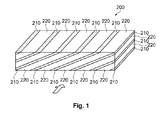
- FIG. 1 is a pattern diagram showing the constitution of the sound absorbing body.
- the sound absorbing body 200 is an item that absorbs noise (does sound absorption) for electronic devices and the like, for example.
- noise does sound absorption
- FIG. 1 with the lateral cross section view (arrow direction in the drawing) of the rectangular solid shaped sound absorbing body 200, one sound absorbing body 200 has low density non-dense parts 220 and dense parts 210 of a higher density than the non-dense parts 220, and the non-dense parts (layers) 220 and the dense parts (layers) 210 are alternately laminated obliquely.
- This oblique lamination extends in the direction orthogonal to the surface at which the oblique lamination can be seen (the direction orthogonal to the front surface shown in Fig. 1 , which is viewed with the lateral cross section).
- the word 'oblique' in 'oblique lamination' means oblique in relation to the surface orthogonal to the surface at which the oblique lamination can be seen. In other words, the lamination extends obliquely to the top surface and side surface shown in Fig. 1 .
- the sound absorbing body 200 has two surfaces (the top and side surfaces in Fig. 1 ) in which the laminations are in parallel and the one surface (the front surface in Fig.
- the width dimension and the lamination count and the like of the non-dense parts 220 and the dense parts 210 can be set as appropriate.
- lamination is done such that the thickness of the lamination direction of the non-dense parts 220 is thicker than the thickness of the lamination direction of the dense parts 210.
- the thickness of the layer corresponding to the non-dense parts 220 becomes thicker, so at the surface of the sound absorbing body 200, the non-dense parts 220 emerge broader than the dense parts 210, so reflection of sound on the surface of the sound absorbing body 200 is reduced, and it is possible to increase the sound absorbing effect.
- the entry path for sound reflected by the dense part 210 becomes longer, and it is possible to further increase the sound absorbing properties.
- the sound absorbing body 200 is an item formed from a mixture including cellulose fiber, molten resin, and flame retardant, and the density of the non-dense parts 220 and the dense parts 210 is the density of the cellulose fiber, the molten resin, or the flame retardant.
- the cellulose fiber is an item for which a pulp sheet or the like is fibrillated into fiber form using a dry type defibrating machine such as a rotary crushing device, for example.
- the molten resin is an item that binds between cellulose fibers, maintains suitable strength (hardness or the like) for the sound absorbing body 200, prevents paper powder and fiber from scattering, and contributes to maintaining the shape of the sound absorbing body 200.
- For the molten resin it is possible to use various modes such as fiber form, powder form and the like. Then, by heating the mixture with cellulose fiber and molten resin mixed, it is possible to melt the molten resin, and to fuse the cellulose fibers and harden them.
- the molten resin be in a fiber form that easily entwines with paper fibers in the fibrillated material.
- the flame retardant is an item added to give flame resistance to the sound absorbing body 200.
- the flame retardant for example, it is possible to use inorganic materials such as aluminum hydroxide, magnesium hydroxide and the like, or phosphorous based organic materials (e.g. aromatic phosphate such as triphenyl phosphate or the like).
- the sound absorbing body 200 forming method for example, a mixture in which cellulose fiber, molten resin, and flame retardant are mixed is placed in a sieve, and this is deposited on a mesh belt arranged beneath the sieve to form a deposit. At this time, the mesh belt is moved at a designated speed, and the mixture is deposited so as to form a non-dense density part 220 and a denser part 210 for which the density is high. Then, the formed deposited substance undergoes pressurization heat treatment. By doing this, the molten resin is melted, and this is formed to a desired thickness. Furthermore, by die cutting to a desired dimension, the sound absorbing body 200 is formed.
- the sound absorbing body 200 formed in this way has formed non-dense density parts 220, and dense parts 210 of a higher density than that of the non-dense density parts 220. Because of that, sound is reflected by the dense parts 210, and by the reflected sound being propagated by the non-dense parts 220, the sound is attenuated, undergoing sound absorption.
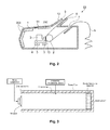
- FIG. 2 is a cross section diagram showing the constitution of the printer.
- the printer 10 of this embodiment performs printing by giving an impact using a printing wire (not illustrated) provided inside the printing head 3 via an ink ribbon 13 on printing paper 6 as a printing medium arranged between a platen 2 and the printing head 3.
- the printing paper 6 is fed from the paper feeding port 7 provided in the case member 1 of the printer 10 and wound on the platen 2, printing is performed by the printing head 3 (in addition to numbers, letters and the like, this is a broad concept also including printing graphs using dots or the like), and the paper is ejected from a paper ejection port 9.
- a carriage 4 can be guided by a guide shaft 5 and moved in the axial direction.
- the ink ribbon 13 is interposed between the printing head 3 and the printing paper 6, and the printing head 3 fixed to the carriage 4 performs printing by driving a plurality of printing wires provided inside the printing head 3 at a desired timing while moving in the axial direction.
- a freely openable/closable cover 11 and a paper ejection port cover 12 are attached to a case member 1, and the paper ejection port cover 12 is rotatably connected to the cover 11. Also, the paper ejection port cover 12 is constituted with a transparent, light member, so the printing paper 6 is easy to see, and it is easy to take it out. Then, the printed printing paper 6 is ejected from the paper ejection port 9 along a paper guide 8.
- the printer 10 is equipped with the sound absorbing body 200 that absorbs noise (does sound absorption).
- the constitution of the sound absorbing body 200 is the same as the constitution in FIG. 1 , so we will omit a description.
- the sound absorbing body 200 is arranged at the part corresponding to the periphery of the printing head 3 of the case member 1. In specific terms, it is arranged at the part corresponding to the side opposite to the drive part of the printing head 3 of the case member 1. Furthermore, the sound absorbing body 200 is also arranged on the cover 11 corresponding to above the printing head 3.
- the generated noise enters the sound absorbing body 200, and while the sound is being reflected by the dense parts 210, the reflected sound is propagated by the non-dense parts 220, so in that process, the sound is effectively absorbed, and it is possible to prevent the diffusion of noise inside the case member 1.
- a pulp sheet cut into several cm using a cutting machine was fibrillated into floc using a turbo mill (made by Turbo Kogyo Co., Ltd.).
- a mixture C1 in which 100 weight parts of cellulose fiber, 15 weight parts of molten fiber, and 10 weight parts of flame retardant were air mixed and a mixture C2 in which 100 weight parts of cellulose fiber, 25 weight parts of molten fiber, and 10 weight parts of flame retardant were air mixed were alternately deposited on a mesh belt.
- mixtures C1 and C2 were alternately continuously deposited while moving the mesh belt. It is also possible to deposit while suctioning with a suction device. With example 1, the mixture C1 and the mixture C2 were alternately deposited six times each. Then, the deposited deposit material underwent pressurization heat treatment at 200 °C. After that, this was cut to ⁇ 29 mm and 10 mm thick to form sound absorbing body A.
- a mixture C1 for which 100 weight parts of cellulose fiber, 15 weight parts of molten fiber, and 10 weight parts of flame retardant were air mixed and a mixture C3 for which 100 weight parts of cellulose fiber, 15 weight parts of molten fiber, and 20 weight parts of flame retardant were air mixed were alternately deposited on a mesh belt.
- a mixture C1 for which 100 weight parts of cellulose fiber, 15 weight parts of molten fiber, and 10 weight parts of flame retardant were air mixed was deposited on a mesh belt. At this time, mixture C1 was deposited while moving the mesh belt. After that, the deposited mixture C1 deposit material underwent pressurization heat treatment at 200 °C. Then, mixture C4 for which 150 weight parts of cellulose fiber, 15 weight parts of molten fiber, and 10 weight parts of flame retardant were air mixed was deposited on the pressurization heat treated mixture C1. At this time, mixture C4 was deposited while moving the mesh belt. After that, the deposited mixture C4 deposit material underwent pressurization heat treatment at 200 °C.
- mixture C 1 and mixture C4 were alternately deposited, and underwent pressurization heat treatment.
- the mixture C1 and the mixture C4 were alternately deposited six times each. After that, this was cut to ⁇ 29 mm and 10 mm thick to form sound absorbing body C.
- sound absorbing body C non-dense parts (0.15 g/cm 3 ) and dense parts (0.17 g/cm 3 ) according to the difference in the cellulose fiber volume were repeatedly laminated and an oblique laminated body was formed.
- a mixture C1 for which 100 weight parts of cellulose fiber, 15 weight parts of molten fiber, and 10 weight parts of flame retardant were air mixed was deposited on a bottom surface having a oblique shape.
- a mixture C2 for which 100 weight parts of cellulose fiber, 25 weight parts of molten fiber, and 10 weight parts of flame retardant were air mixed was deposited on the deposited mixture C1.
- the mixtures C1 and C2 were alternately deposited.
- the deposited deposit material underwent pressurization heat treatment at 200 °C. After that, this was cut to ⁇ 29 mm and 10 mm thick to form sound absorbing body D.
- a mixture C1 for which 100 weight parts of cellulose fiber, 15 weight parts of molten fiber, and 10 weight parts of flame retardant were air mixed was deposited on a mesh belt.
- a mixture C2 for which 100 weight parts of cellulose fiber, 25 weight parts of molten fiber, and 10 weight parts of flame retardant were air mixed was deposited on the deposited mixture C1.
- the mesh belt was not moved.
- the mixtures C 1 and C2 were alternately deposited.
- the deposited deposit material underwent pressurization heat treatment at 200 °C. After that, this was cut to ⁇ 29 mm and 10 mm thick to form sound absorbing body R.
- FIG. 3 is a pattern diagram showing the method for evaluating the sound absorption properties.
- the equipment for evaluating the sound absorbing properties includes a sound tube, a bottom part provided at one end part of the sound tube, an opening part opened at the other end part of the sound tube, a microphone arranged inside the sound tube, a speaker arranged in the opening part of the sound tube, a noise generator connected to the speaker, and an arithmetic processing device or the like.
- the sound absorbing body W of examples 1 through 4 is arranged such that the obliquely laminated surface (in other words, the front or side surface in Fig. 1 ) faces the speaker, and the sound absorbing body W of the comparison example 1 is arranged such that the surface for which the non-dense part and the dense part are laminated in planar form faces the speaker.
- the sound absorption rate for all frequency areas corresponding to all the examples is a numerical value greater than the absorption rate with the comparison example 1, and the effect was of having excellent sound absorbing properties.
- the dense parts and the non-dense parts are alternately laminated obliquely with the sound absorbing body A through the sound absorbing body D of example 1 through example 4, so the path for propagating reflected sound by the non-dense parts while the sound is reflected by the dense parts is formed to be long.
- the oblique lamination of the non-dense parts and the dense parts which is a feature point of this application can be understood by being seen with the eye by the external appearance in some cases, but cannot be understood by being viewed in some cases when there is only a slight difference between the non-density and the density.
- a verification method in such a case after a liquid such as water or the like is included, when the sound absorbing body is torn off, the layer direction can be understood. Also, when a liquid with color such as ink or the like is dripped, if there is a layer for which infiltration occurs easily obliquely, this can be called non-dense/dense oblique lamination.
- the sound absorbing body 200 was a rectangular solid, but the invention is not limited to this. It is also possible to have a notch or recess in a portion of the rectangular solid, or to have a circular arc part or a sloped part rather than a rectangular solid.
- lamination was done such that the thickness of the layer corresponding to the non-dense parts 220 was thicker than the thickness of the layer corresponding to the dense parts 210, but the invention is not limited to his constitution.
- the thickness of the layer corresponding to the non-dense parts 220 be the same thickness as the thickness of the layer corresponding to the dense parts 210. Even when set in this way, it is possible to increase the sound absorbing effect.
- densities are numbers for the greatest locations and the least locations.
- the pulp sheet includes wood pulp such as of conifer trees, broad leafed trees and the like, non-wood plant fibers such as of hemp, cotton, kenaf and the like, and used paper and the like.
- cellulose fiber was the main constituent, but as long as it is a material that absorbs sound, and can be given density differences, this is not limited to cellulose fiber. It is also possible to use fiber with a raw material of a plastic such as polyurethane or polyethylene terephthalate (PET) or the like, or another fiber such as wool or the like.
- a plastic such as polyurethane or polyethylene terephthalate (PET) or the like
- PET polyethylene terephthalate
- the method for forming the sound absorbing body is not limited to the method noted with the embodiments noted above. As long as the features of this application can be presented, another manufacturing method such as a wet method or the like can also be used.
Landscapes
- Physics & Mathematics (AREA)
- Engineering & Computer Science (AREA)
- Acoustics & Sound (AREA)
- Multimedia (AREA)
- Soundproofing, Sound Blocking, And Sound Damping (AREA)
- Accessory Devices And Overall Control Thereof (AREA)
- Building Environments (AREA)
Abstract
Description
- This application claims priority to Japanese Patent Application No.
2013-026333 filed on February 14, 2013 2013-026333 - The present invention relates to a sound absorbing body and an electronic device.
- In the past, for example, with printers, items have been known for which a sound absorbing member for absorbing noise emanating from a head, platen or the like is equipped inside a case member (see Japanese Unexamined Patent Publication No.
H05-254214 - However, since the density of the sound absorbing member noted above is almost uniform, it was necessary to make the thickness of the sound absorbing member even thicker to further increase the sound absorbing effect. Then, there was demand for a design that considered the thickness of the sound absorbing member when arranging the sound absorbing member inside an electronic device, and when the sound absorbing material became thicker, there was the problem that the external dimensions of electronic devices such as a printer or the like became larger.
- The present invention was created to address at least a portion of the problems described above, and can be realized as the modes or aspects below.
- A sound absorbing body according to one aspect includes parts of different densities including a plurality of non-dense parts of lower density and a plurality of dense parts of higher density. The non-dense parts and the dense parts are alternately laminated obliquely.
- With this constitution, when sound enters the sound absorbing body, while the sound is reflected by the dense part, the sound is propagated by the non-dense parts formed between the dense parts, so it is possible to attenuate the sound. Furthermore, the dense parts and non-dense parts are laminated obliquely, so the path for the sound to be propagated while being reflected is formed to be longer. By doing this, even if the thickness of the sound absorbing body is the same, the sound entry path inside the sound absorbing body is set to be longer, so it is possible to increase the sound absorbing effect without making the thickness of the sound absorbing body thicker. Also, the sound absorbing body is constituted as one unit. Specifically, it is formed as an integral unit. Because of this, for example, compared to an item for which the dense parts and the non-dense parts are formed separately and alternately laminated, management of adhesion of the lamination boundary or the like is unnecessary, so it is possible to perform handling easily.
- With the sound absorbing body of the aspect noted above, a thickness in a lamination direction of the non-dense parts is preferably thicker than a thickness in the lamination direction of the dense parts.
- With this constitution, the layer corresponding to the non-dense part becomes thicker (broader), so the sound reflection at the surface part of the sound absorbing body is decreased. By doing this, it is possible to increase the sound absorbing effect. Furthermore, when the layer corresponding to the non-dense part becomes thicker (broader), the sound propagation path becomes larger. Therefore, it is possible to attenuate the sound with even better efficiency.
- With the sound absorbing body of the aspect noted above, the dense parts and the non-dense parts preferably include cellulose fibers, and the density of the dense parts and the non-dense parts is preferably a density of the cellulose fibers.
- With this constitution, by the sound that enters the sound absorbing body making the cellulose fibers vibrate, it is possible to increase the sound absorbing effect.
- With the sound absorbing body of the aspect noted above, the dense parts and the non-dense parts preferably include molten resin, and the density of the dense parts and the non-dense parts is preferably a density of the molten resin.
- With this constitution, by changing the volume of the molten fiber, it is possible to form the non-dense parts and the dense parts easily.
- With the sound absorbing body of the aspect noted above, the dense parts and the non-dense parts preferably include flame retardant, and the density of the dense parts and the non-dense parts is preferably a density of the flame retardant.
- With this constitution, by changing the volume of the flame retardant, it is possible to form the non-dense parts and the dense parts easily.
- With the sound absorbing body of the aspect noted above, the dense parts and the non-dense parts preferably include molten resin, and the non-dense parts and the dense parts are preferably bonded by the molten resin.
- An electronic device according to another aspect is equipped with the sound absorbing body noted above.
- With this constitution, it is possible to provide an electronic device with an excellent sound absorption effect. In this case, the sound absorbing body has high sound absorption efficiency, so it is possible to inhibit the thickness of the sound absorbing body. By doing this, it is also possible to make the electronic device more compact. Here, for example, the electronic device means items including various types of electronic device that emit sound such as printers or the like.
- Embodiments of the present invention will now be described by way of further example only and with reference to the accompanying drawings, in which:
-
FIG. 1 is a pattern diagram showing the constitution of a sound absorbing body. -
FIG. 2 is a cross section diagram showing the constitution of the printer. -
FIG. 3 is a pattern diagram showing the evaluation method of the sound absorbing properties. - Following, we will describe embodiments of the present invention while referring to the drawings. In each drawing hereafter, to make each component and the like be a size of a level that is recognizable, the scale of each component and the like is shown different from actuality.
- First, we will describe the constitution of the sound absorbing body.
FIG. 1 is a pattern diagram showing the constitution of the sound absorbing body. Thesound absorbing body 200 is an item that absorbs noise (does sound absorption) for electronic devices and the like, for example. As shown inFIG. 1 , with the lateral cross section view (arrow direction in the drawing) of the rectangular solid shapedsound absorbing body 200, onesound absorbing body 200 has low densitynon-dense parts 220 anddense parts 210 of a higher density than thenon-dense parts 220, and the non-dense parts (layers) 220 and the dense parts (layers) 210 are alternately laminated obliquely. This oblique lamination extends in the direction orthogonal to the surface at which the oblique lamination can be seen (the direction orthogonal to the front surface shown inFig. 1 , which is viewed with the lateral cross section). Also, the word 'oblique' in 'oblique lamination' means oblique in relation to the surface orthogonal to the surface at which the oblique lamination can be seen. In other words, the lamination extends obliquely to the top surface and side surface shown inFig. 1 . By obliquely laminating a plurality of thenon-dense parts 220 and thedense parts 210 on one (the front surface viewed with the lateral cross section) surface in this way, it is possible to make thenon-dense parts 220 and thedense parts 210 alternately appear repeatedly on each surface of thesound absorbing body 200 orthogonal to the one surface. At the surfaces orthogonal to the one surface, rather than oblique lamination in relation to each surface orthogonal to this surface, it becomes a parallel or orthogonal layer. In other words, thesound absorbing body 200 has two surfaces (the top and side surfaces inFig. 1 ) in which the laminations are in parallel and the one surface (the front surface inFig. 1 ) in which the laminations are oblique to provide three mutually orthogonal surfaces. Even when sound enters from either surface of these two surfaces, it is possible to obtain a sound absorbing effect. Of these two surfaces, it is preferable to have sound enter from the surface that has a broader surface area. - The width dimension and the lamination count and the like of the
non-dense parts 220 and thedense parts 210 can be set as appropriate. With this embodiment, lamination is done such that the thickness of the lamination direction of thenon-dense parts 220 is thicker than the thickness of the lamination direction of thedense parts 210. By using this kind of constitution, the thickness of the layer corresponding to thenon-dense parts 220 becomes thicker, so at the surface of thesound absorbing body 200, thenon-dense parts 220 emerge broader than thedense parts 210, so reflection of sound on the surface of thesound absorbing body 200 is reduced, and it is possible to increase the sound absorbing effect. Also, the entry path for sound reflected by thedense part 210 becomes longer, and it is possible to further increase the sound absorbing properties. - It is also possible to laminate a plurality of
sound absorbing bodies 200. By doing this, it is possible to further increase the sound absorbing effect. - The
sound absorbing body 200 is an item formed from a mixture including cellulose fiber, molten resin, and flame retardant, and the density of thenon-dense parts 220 and thedense parts 210 is the density of the cellulose fiber, the molten resin, or the flame retardant. - The cellulose fiber is an item for which a pulp sheet or the like is fibrillated into fiber form using a dry type defibrating machine such as a rotary crushing device, for example. The molten resin is an item that binds between cellulose fibers, maintains suitable strength (hardness or the like) for the
sound absorbing body 200, prevents paper powder and fiber from scattering, and contributes to maintaining the shape of thesound absorbing body 200. For the molten resin, it is possible to use various modes such as fiber form, powder form and the like. Then, by heating the mixture with cellulose fiber and molten resin mixed, it is possible to melt the molten resin, and to fuse the cellulose fibers and harden them. It is preferable to fuse at a temperature of a level that will not cause thermal degradation of the cellulose fibers and the like. Also, it is preferable that the molten resin be in a fiber form that easily entwines with paper fibers in the fibrillated material. Furthermore, it is preferable to use a core-sheath structure conjugated fiber. With the core-sheath structure molten resin, the surrounding sheath part melts at a low temperature, and by the fiber form core part bonding with the molten resin itself or with the cellulose fiber, it is possible to make a strong bond. - The flame retardant is an item added to give flame resistance to the
sound absorbing body 200. As the flame retardant, for example, it is possible to use inorganic materials such as aluminum hydroxide, magnesium hydroxide and the like, or phosphorous based organic materials (e.g. aromatic phosphate such as triphenyl phosphate or the like). - As the
sound absorbing body 200 forming method, for example, a mixture in which cellulose fiber, molten resin, and flame retardant are mixed is placed in a sieve, and this is deposited on a mesh belt arranged beneath the sieve to form a deposit. At this time, the mesh belt is moved at a designated speed, and the mixture is deposited so as to form anon-dense density part 220 and adenser part 210 for which the density is high. Then, the formed deposited substance undergoes pressurization heat treatment. By doing this, the molten resin is melted, and this is formed to a desired thickness. Furthermore, by die cutting to a desired dimension, thesound absorbing body 200 is formed. - The
sound absorbing body 200 formed in this way has formednon-dense density parts 220, anddense parts 210 of a higher density than that of thenon-dense density parts 220. Because of that, sound is reflected by thedense parts 210, and by the reflected sound being propagated by thenon-dense parts 220, the sound is attenuated, undergoing sound absorption. - Next, we will describe the constitution of the electronic device. With this embodiment, we will describe the constitution of a printer as the electronic device.
FIG. 2 is a cross section diagram showing the constitution of the printer. As shown inFIG. 2 , theprinter 10 of this embodiment performs printing by giving an impact using a printing wire (not illustrated) provided inside theprinting head 3 via anink ribbon 13 onprinting paper 6 as a printing medium arranged between aplaten 2 and theprinting head 3. - The
printing paper 6 is fed from thepaper feeding port 7 provided in thecase member 1 of theprinter 10 and wound on theplaten 2, printing is performed by the printing head 3 (in addition to numbers, letters and the like, this is a broad concept also including printing graphs using dots or the like), and the paper is ejected from apaper ejection port 9. Acarriage 4 can be guided by aguide shaft 5 and moved in the axial direction. Theink ribbon 13 is interposed between theprinting head 3 and theprinting paper 6, and theprinting head 3 fixed to thecarriage 4 performs printing by driving a plurality of printing wires provided inside theprinting head 3 at a desired timing while moving in the axial direction. - A freely openable/
closable cover 11 and a paperejection port cover 12 are attached to acase member 1, and the paperejection port cover 12 is rotatably connected to thecover 11. Also, the paperejection port cover 12 is constituted with a transparent, light member, so theprinting paper 6 is easy to see, and it is easy to take it out. Then, the printedprinting paper 6 is ejected from thepaper ejection port 9 along a paper guide 8. - Also, the
printer 10 is equipped with thesound absorbing body 200 that absorbs noise (does sound absorption). The constitution of thesound absorbing body 200 is the same as the constitution inFIG. 1 , so we will omit a description. With this embodiment, thesound absorbing body 200 is arranged at the part corresponding to the periphery of theprinting head 3 of thecase member 1. In specific terms, it is arranged at the part corresponding to the side opposite to the drive part of theprinting head 3 of thecase member 1. Furthermore, thesound absorbing body 200 is also arranged on thecover 11 corresponding to above theprinting head 3. By doing this, when noise occurs with driving of theprinting head 3, the generated noise enters thesound absorbing body 200, and while the sound is being reflected by thedense parts 210, the reflected sound is propagated by thenon-dense parts 220, so in that process, the sound is effectively absorbed, and it is possible to prevent the diffusion of noise inside thecase member 1. - With this embodiment, we described an example of a printer as the electronic device, but the invention is not limited to this, and it is also possible to apply this to various types of electronic devices.
- As described above, with this embodiment, the following effects can be obtained.
- (1) When sound enters the
sound absorbing body 200, sound is propagated by thenon-dense part 220 formed between twodense parts 210 while the sound is being reflected by thedense part 210, so it is possible to attenuate the sound. Furthermore, thedense parts 210 and thenon-dense parts 220 are laminated obliquely, so the path for propagating sound while it is reflected is formed to be longer. By doing this, even when the thickness of thesound absorbing body 200 is the same, it is possible to set the propagation path for the sound that enters thesound absorbing body 200 to be longer, so it is possible to increase the sound absorption effect without making the thickness of thesound absorbing body 200 thicker. Also, thesound absorbing body 200 is constituted as one unit. Specifically, it is formed as an integrated unit. Because of that, for example compared to an item for which thedense parts 210 and thenon-dense parts 220 are formed separately and alternately laminated, management of the adhesion of the lamination boundaries and the like is unnecessary, and it is possible to perform handling easily. - (2) With the
printer 10 equipped with thesound absorbing body 200 noted above, it is possible to efficiently reduce noise during driving of theprinting head 3. - Next, we will describe specific examples of the present invention.
- A pulp sheet cut into several cm using a cutting machine was fibrillated into floc using a turbo mill (made by Turbo Kogyo Co., Ltd.).
- This was polyethylene having a core-sheath structure, with the sheath melted at 100 °C or greater, and the core being 1.7 dtex molten fiber consisting of polyester (Tetoron, made by Teijin, Ltd.).
- Aluminum hydroxide B53 (made by Nippon Light Metal Co., Ltd.)
- A mixture C1 in which 100 weight parts of cellulose fiber, 15 weight parts of molten fiber, and 10 weight parts of flame retardant were air mixed and a mixture C2 in which 100 weight parts of cellulose fiber, 25 weight parts of molten fiber, and 10 weight parts of flame retardant were air mixed were alternately deposited on a mesh belt. At this time, mixtures C1 and C2 were alternately continuously deposited while moving the mesh belt. It is also possible to deposit while suctioning with a suction device. With example 1, the mixture C1 and the mixture C2 were alternately deposited six times each. Then, the deposited deposit material underwent pressurization heat treatment at 200 °C. After that, this was cut to ø 29 mm and 10 mm thick to form sound absorbing body A. With that sound absorbing body A, non-dense parts (0.15 g/cm3) and dense parts (0.17 g/cm3) according to the difference in the molten resin volume were repeatedly laminated and an oblique laminated body was formed.
- A mixture C1 for which 100 weight parts of cellulose fiber, 15 weight parts of molten fiber, and 10 weight parts of flame retardant were air mixed and a mixture C3 for which 100 weight parts of cellulose fiber, 15 weight parts of molten fiber, and 20 weight parts of flame retardant were air mixed were alternately deposited on a mesh belt. At this time, so that mixtures C1 and C3 were laminated obliquely, mixtures C1 and C3 were alternately continuously deposited while moving the mesh belt. It is also possible to deposit while suctioning with a suction device. With example 2, the mixture C1 and the mixture C3 were alternately deposited six times each. Then, the deposited deposit material underwent pressurization heat treatment at 200 °C. After that, this was cut to Ø 29 mm and 10 mm thick to form sound absorbing body B. With that sound absorbing body B, non-dense parts (0.15 g/cm3) and dense parts (0.17 g/cm3) according to the difference in the flame retardant volume were repeatedly laminated and an oblique laminated body was formed. With this example 2, it is not necessary to include flame retardant uniformly in the thickness direction of the sound absorbing body B, since more flame retardant was used in mixture C3 used to form the thinner denser layer, so it was possible to reduce the volume of flame retardant used.
- A mixture C1 for which 100 weight parts of cellulose fiber, 15 weight parts of molten fiber, and 10 weight parts of flame retardant were air mixed was deposited on a mesh belt. At this time, mixture C1 was deposited while moving the mesh belt. After that, the deposited mixture C1 deposit material underwent pressurization heat treatment at 200 °C. Then, mixture C4 for which 150 weight parts of cellulose fiber, 15 weight parts of molten fiber, and 10 weight parts of flame retardant were air mixed was deposited on the pressurization heat treated mixture C1. At this time, mixture C4 was deposited while moving the mesh belt. After that, the deposited mixture C4 deposit material underwent pressurization heat treatment at 200 °C. Thereafter,
mixture C 1 and mixture C4 were alternately deposited, and underwent pressurization heat treatment. With example 3, the mixture C1 and the mixture C4 were alternately deposited six times each. After that, this was cut to Ø 29 mm and 10 mm thick to form sound absorbing body C. With that sound absorbing body C, non-dense parts (0.15 g/cm3) and dense parts (0.17 g/cm3) according to the difference in the cellulose fiber volume were repeatedly laminated and an oblique laminated body was formed. - A mixture C1 for which 100 weight parts of cellulose fiber, 15 weight parts of molten fiber, and 10 weight parts of flame retardant were air mixed was deposited on a bottom surface having a oblique shape. Next, a mixture C2 for which 100 weight parts of cellulose fiber, 25 weight parts of molten fiber, and 10 weight parts of flame retardant were air mixed was deposited on the deposited mixture C1. After that, the mixtures C1 and C2 were alternately deposited. The deposited deposit material underwent pressurization heat treatment at 200 °C. After that, this was cut to Ø 29 mm and 10 mm thick to form sound absorbing body D. With that sound absorbing body D, non-dense parts (0.15 g/cm3) and dense parts (0.17 g/cm3) according to the difference in the molten resin volume were repeatedly laminated and an oblique laminated body was formed.
- A mixture C1 for which 100 weight parts of cellulose fiber, 15 weight parts of molten fiber, and 10 weight parts of flame retardant were air mixed was deposited on a mesh belt. Next, a mixture C2 for which 100 weight parts of cellulose fiber, 25 weight parts of molten fiber, and 10 weight parts of flame retardant were air mixed was deposited on the deposited mixture C1. At this time, the mesh belt was not moved. After that, the
mixtures C 1 and C2 were alternately deposited. Then, the deposited deposit material underwent pressurization heat treatment at 200 °C. After that, this was cut to Ø 29 mm and 10 mm thick to form sound absorbing body R. With that sound absorbing body R, though non-dense parts (0.15 g/cm3) and dense parts (0.17 g/cm3) appeared according to the difference in the molten fiber volume, in contrast to the constitution of the sound absorbing bodies A, B, C, and D formed with example 1 through example 4, a laminated body was formed for which the non-dense parts and the dense parts were laminated in planar form. Specifically, the non-dense parts and the dense parts were not laminated obliquely. - Next, an evaluation of sound absorption properties was performed for example 1 through example 4 and comparison example 1 noted above. This sound absorbing property evaluation measures the sound absorption rate (normal incident sound absorption rate) based on JIS A 1405-2. Specific details are as noted below.
-
FIG. 3 is a pattern diagram showing the method for evaluating the sound absorption properties. As shown inFIG. 3 , the equipment for evaluating the sound absorbing properties includes a sound tube, a bottom part provided at one end part of the sound tube, an opening part opened at the other end part of the sound tube, a microphone arranged inside the sound tube, a speaker arranged in the opening part of the sound tube, a noise generator connected to the speaker, and an arithmetic processing device or the like. - After the sound absorbing body W is set in the bottom part of the sound tube, sound of a designated frequency is radiated from the speaker, and a sound field is generated inside the sound tube. Then, the normal incident sound absorption rate is calculated based on the sound pressure signal obtained from the microphone inside the sound tube. By this evaluation, it is possible to evaluate the sound absorbing properties of the sound absorbing body W. The sound absorbing body W of examples 1 through 4 is arranged such that the obliquely laminated surface (in other words, the front or side surface in
Fig. 1 ) faces the speaker, and the sound absorbing body W of the comparison example 1 is arranged such that the surface for which the non-dense part and the dense part are laminated in planar form faces the speaker. - Sound absorption was evaluated for example 1 through example 4 and comparison example 1 noted above. The evaluation results are shown in table 1. With table 1, the sound absorption rate for each frequency of example 1 through example 4 is expressed when the sound absorption rate of the comparison example 1 is set as 1. Therefore, when the number is higher than the
sound absorption rate 1 with the comparison example 1, the evaluation is that there is a greater sound absorption effect. Meanwhile, when the number is smaller than theabsorption rate 1 with the comparison example 1, the evaluation is that there is a low sound absorption effect.Table 1 1000 Hz 2000 Hz 4000 Hz Example 1 1.46 1.18 1.19 Example 2 1.52 1.50 1.19 Example 3 1.68 1.26 1.40 Example 4 1.04 1.24 1.19 Comparison Example 1 1 1 1 - As shown in table 1, with example 1 through example 4, the sound absorption rate for all frequency areas corresponding to all the examples is a numerical value greater than the absorption rate with the comparison example 1, and the effect was of having excellent sound absorbing properties. This is because the dense parts and the non-dense parts are alternately laminated obliquely with the sound absorbing body A through the sound absorbing body D of example 1 through example 4, so the path for propagating reflected sound by the non-dense parts while the sound is reflected by the dense parts is formed to be long.
- The oblique lamination of the non-dense parts and the dense parts which is a feature point of this application can be understood by being seen with the eye by the external appearance in some cases, but cannot be understood by being viewed in some cases when there is only a slight difference between the non-density and the density. As a verification method in such a case, after a liquid such as water or the like is included, when the sound absorbing body is torn off, the layer direction can be understood. Also, when a liquid with color such as ink or the like is dripped, if there is a layer for which infiltration occurs easily obliquely, this can be called non-dense/dense oblique lamination. When the overall sound absorbing body has uniform density, when ink is dropped, it infiltrates almost uniformly laterally while infiltrating downward by gravity. Also, when there is a horizontal non-dense/dense layer, there is a layer for which lateral infiltration occurs easily.
- Following, we will describe modification examples.
- With the embodiments noted above, to prevent fuzz on the surface of the
sound absorbing body 200 and the like, it is possible to adhere a thin non-woven cloth to the surface. Since adhered non-woven cloth is thinner than thesound absorbing body 200, there is little effect on the sound absorbing properties. - With the embodiments noted above, the
sound absorbing body 200 was a rectangular solid, but the invention is not limited to this. It is also possible to have a notch or recess in a portion of the rectangular solid, or to have a circular arc part or a sloped part rather than a rectangular solid. - With the embodiments noted above, lamination was done such that the thickness of the layer corresponding to the
non-dense parts 220 was thicker than the thickness of the layer corresponding to thedense parts 210, but the invention is not limited to his constitution. For example, it is also possible to have the thickness of the layer corresponding to thenon-dense parts 220 be the same thickness as the thickness of the layer corresponding to thedense parts 210. Even when set in this way, it is possible to increase the sound absorbing effect. - We noted the density for each embodiment and comparison example, but these are merely examples. Also, densities are numbers for the greatest locations and the least locations.
- With the embodiments noted above, the pulp sheet includes wood pulp such as of conifer trees, broad leafed trees and the like, non-wood plant fibers such as of hemp, cotton, kenaf and the like, and used paper and the like.
- With the embodiments noted above, cellulose fiber was the main constituent, but as long as it is a material that absorbs sound, and can be given density differences, this is not limited to cellulose fiber. It is also possible to use fiber with a raw material of a plastic such as polyurethane or polyethylene terephthalate (PET) or the like, or another fiber such as wool or the like.
- The method for forming the sound absorbing body is not limited to the method noted with the embodiments noted above. As long as the features of this application can be presented, another manufacturing method such as a wet method or the like can also be used.
- In understanding the scope of the present invention, the term "comprising" and its derivatives, as used herein, are intended to be open ended terms that specify the presence of the stated features, elements, components, groups, integers, and/or steps, but do not exclude the presence of other unstated features, elements, components, groups, integers and/or steps. The foregoing also applies to words having similar meanings such as the terms, "including", "having" and their derivatives. Also, the terms "part," "section," "portion," "member" or "element" when used in the singular can have the dual meaning of a single part or a plurality of parts. Finally, terms of degree such as "substantially", "about" and "approximately" as used herein mean a reasonable amount of deviation of the modified term such that the end result is not significantly changed. For example, these terms can be construed as including a deviation of at least ± 5% of the modified term if this deviation would not negate the meaning of the word it modifies.
- While only selected embodiments have been chosen to illustrate the present invention, it will be apparent to those skilled in the art from this disclosure that various changes and modifications can be made herein without departing from the scope of the invention as defined in the appended claims. Furthermore, the foregoing descriptions of the embodiments according to the present invention are provided for illustration only, and not for the purpose of limiting the invention as defined by the appended claims.
Claims (7)
- A sound absorbing body (200) comprising:parts of different densities including a plurality of non-dense parts (220) of lower density and a plurality of dense parts (210) of higher density with the non-dense parts and the dense parts being alternately laminated obliquely.
- The sound absorbing body according to claim 1, wherein
a thickness in a lamination direction of the non-dense parts (220) is thicker than a thickness in the lamination direction of the dense parts (210). - The sound absorbing body according to claim 1 or claim 2, wherein
the dense parts and the non-dense parts include cellulose fibers, and
the density of the dense parts and the non-dense parts varies based on the amount of the cellulose fibers. - The sound absorbing body according to any one of the preceding claims, wherein
the dense parts and the non-dense parts include molten resin, and
the density of the dense parts and the non-dense parts varies based on the amount of the molten resin. - The sound absorbing body according to any one of the preceding claims, wherein
the dense parts and the non-dense parts include flame retardant, and
the density of the dense parts and the non-dense parts varies based on the amount of the flame retardant. - The sound absorbing body according to any one of the preceding claims, wherein
the dense parts and the non-dense parts include molten resin, and
the non-dense parts and the dense parts are bonded by the molten resin. - An electronic device comprising the sound absorbing body according to any one of the preceding claims.
Applications Claiming Priority (1)
| Application Number | Priority Date | Filing Date | Title |
|---|---|---|---|
| JP2013026333A JP6175789B2 (en) | 2013-02-14 | 2013-02-14 | Sound absorber, electronic device |
Publications (2)
| Publication Number | Publication Date |
|---|---|
| EP2767976A2 true EP2767976A2 (en) | 2014-08-20 |
| EP2767976A3 EP2767976A3 (en) | 2016-02-17 |
Family
ID=50239375
Family Applications (1)
| Application Number | Title | Priority Date | Filing Date |
|---|---|---|---|
| EP14155085.5A Withdrawn EP2767976A3 (en) | 2013-02-14 | 2014-02-13 | Sound absorbing body and electronic device |
Country Status (4)
| Country | Link |
|---|---|
| US (1) | US9038769B2 (en) |
| EP (1) | EP2767976A3 (en) |
| JP (1) | JP6175789B2 (en) |
| CN (1) | CN103996397A (en) |
Cited By (1)
| Publication number | Priority date | Publication date | Assignee | Title |
|---|---|---|---|---|
| FI20236434A1 (en) * | 2023-12-22 | 2025-01-03 | Metsaeliitto Osuuskunta | A multi-layered building element and a use thereof |
Families Citing this family (5)
| Publication number | Priority date | Publication date | Assignee | Title |
|---|---|---|---|---|
| JP6175790B2 (en) * | 2013-02-14 | 2017-08-09 | セイコーエプソン株式会社 | Sound absorber, printing device |
| JP6175789B2 (en) * | 2013-02-14 | 2017-08-09 | セイコーエプソン株式会社 | Sound absorber, electronic device |
| JP6136335B2 (en) * | 2013-02-14 | 2017-05-31 | セイコーエプソン株式会社 | Sound absorber, printing device |
| JP6091692B1 (en) * | 2016-09-20 | 2017-03-08 | サン−ゴバン イゾベール | Inorganic fiber laminate, vacuum heat insulating material using the same, and method for producing the same |
| JP2024032161A (en) * | 2022-08-29 | 2024-03-12 | セイコーエプソン株式会社 | Soundproof sheet manufacturing method and soundproof sheet |
Citations (2)
| Publication number | Priority date | Publication date | Assignee | Title |
|---|---|---|---|---|
| JPH05254214A (en) | 1992-03-10 | 1993-10-05 | Seiko Epson Corp | Structure of printer cover |
| US20070275180A1 (en) * | 2006-05-26 | 2007-11-29 | Thompson Gregory J | Fiber-containing composite and method for making the same |
Family Cites Families (38)
| Publication number | Priority date | Publication date | Assignee | Title |
|---|---|---|---|---|
| US3424270A (en) * | 1965-05-12 | 1969-01-28 | Us Plywood Champ Papers Inc | Viscoelastic sound-blocking material with filler of high density particles |
| US3895143A (en) * | 1973-03-16 | 1975-07-15 | Nicolet Ind Inc | Metal-fiber-latex-containing sheet materials |
| US4214646A (en) * | 1978-06-19 | 1980-07-29 | Conwed Corporation | Space divider and acoustic panel |
| US4213516A (en) * | 1978-11-29 | 1980-07-22 | American Seating Company | Acoustical wall panel |
| US4428454A (en) * | 1981-09-24 | 1984-01-31 | Capaul Raymond W | Acoustical panel construction |
| JPS60135997A (en) * | 1983-12-26 | 1985-07-19 | 株式会社日立製作所 | sound absorbing material |
| US4590114A (en) * | 1984-04-18 | 1986-05-20 | Personal Products Company | Stabilized absorbent structure containing thermoplastic fibers |
| US4828932A (en) * | 1986-05-12 | 1989-05-09 | Unix Corporation Ltd. | Porous metallic material, porous structural material and porous decorative sound absorbing material, and methods for manufacturing the same |
| JPS63195043A (en) * | 1987-02-10 | 1988-08-12 | Mazda Motor Corp | Structure for controlling sound in compartment of vehicle |
| US5149920A (en) * | 1989-11-09 | 1992-09-22 | Fiber-Lite Corporation | Acoustical panel and method of making same |
| US5304415A (en) * | 1991-04-15 | 1994-04-19 | Matsushita Electric Works, Ltd. | Sound absorptive material |
| US5684278A (en) * | 1994-11-18 | 1997-11-04 | Lockheed Missiles & Space Co., Inc. | Acoustical ceramic panel and method |
| US5965851A (en) * | 1997-01-28 | 1999-10-12 | Owens Corning Fiberglas Technology, Inc. | Acoustically insulated apparatus |
| US5834711A (en) * | 1997-07-09 | 1998-11-10 | Johns Manville International, Inc. | Sound control through resonance damping |
| WO2000057988A1 (en) * | 1999-03-30 | 2000-10-05 | Chisso Corporation | Filter cartridge |
| US7712580B2 (en) * | 1999-04-20 | 2010-05-11 | Virginia Tech Intellectual Properties, Inc. | Active/passive distributed absorber for vibration and sound radiation control |
| EP1365388A4 (en) * | 2001-01-23 | 2006-07-26 | Kasai Kogyo Kk | Soundproof material for vehicle and method of manufacturing the material |
| KR20040007629A (en) * | 2001-06-01 | 2004-01-24 | 오웬스 코닝 | Multidensity liner/insulator |
| CA2498738A1 (en) * | 2002-09-13 | 2004-03-25 | Cta Acoustics, Inc. | Improved sound absorbing material and process for making |
| US6789646B2 (en) * | 2002-10-11 | 2004-09-14 | Lear Corporation | Tunable sound absorbing and air filtering attenuating device |
| US7070848B2 (en) * | 2002-10-21 | 2006-07-04 | Cascade Engineering, Inc. | Vehicle acoustic barrier |
| US7320739B2 (en) * | 2003-01-02 | 2008-01-22 | 3M Innovative Properties Company | Sound absorptive multilayer composite |
| US7252868B2 (en) * | 2004-01-08 | 2007-08-07 | Certainteed Corporation | Reinforced fibrous insulation product and method of reinforcing same |
| JP4507919B2 (en) * | 2005-03-08 | 2010-07-21 | 豊田合成株式会社 | Exterior material |
| US7651964B2 (en) * | 2005-08-17 | 2010-01-26 | Milliken & Company | Fiber-containing composite and method for making the same |
| US8051950B2 (en) * | 2006-08-03 | 2011-11-08 | Glacier Bay, Inc. | System for reducing acoustic energy |
| US8118177B2 (en) * | 2006-10-04 | 2012-02-21 | Sellars Absorbent Materials, Inc. | Non-woven webs and methods of manufacturing the same |
| WO2008147998A1 (en) * | 2007-05-23 | 2008-12-04 | Maxxon Corporation | Sound insulation layer for corrugated decking flooring system |
| US8261876B2 (en) * | 2010-03-09 | 2012-09-11 | Autoneum Management Ag | Automotive trim part for sound insulation and absorption |
| EP2366541A1 (en) * | 2010-03-17 | 2011-09-21 | Groz-Beckert KG | Fibre compound acoustic dampening material |
| WO2012161695A1 (en) * | 2011-05-24 | 2012-11-29 | Owens Corning Intellectual Capital, Llc | Acoustically insulated machine |
| CN102842303B (en) * | 2011-06-23 | 2015-01-21 | 中国电力科学研究院 | Microporous-fiber composite sound absorbing board |
| WO2013010217A1 (en) * | 2011-07-15 | 2013-01-24 | RAFP Pty Ltd | Noise abatement panel |
| US8496088B2 (en) * | 2011-11-09 | 2013-07-30 | Milliken & Company | Acoustic composite |
| US8925677B2 (en) * | 2012-06-27 | 2015-01-06 | Usg Interiors, Llc | Gypsum-panel acoustical monolithic ceiling |
| JP6175790B2 (en) * | 2013-02-14 | 2017-08-09 | セイコーエプソン株式会社 | Sound absorber, printing device |
| JP6136335B2 (en) * | 2013-02-14 | 2017-05-31 | セイコーエプソン株式会社 | Sound absorber, printing device |
| JP6175789B2 (en) * | 2013-02-14 | 2017-08-09 | セイコーエプソン株式会社 | Sound absorber, electronic device |
-
2013
- 2013-02-14 JP JP2013026333A patent/JP6175789B2/en not_active Expired - Fee Related
-
2014
- 2014-02-11 US US14/177,426 patent/US9038769B2/en not_active Expired - Fee Related
- 2014-02-11 CN CN201410048017.4A patent/CN103996397A/en active Pending
- 2014-02-13 EP EP14155085.5A patent/EP2767976A3/en not_active Withdrawn
Patent Citations (2)
| Publication number | Priority date | Publication date | Assignee | Title |
|---|---|---|---|---|
| JPH05254214A (en) | 1992-03-10 | 1993-10-05 | Seiko Epson Corp | Structure of printer cover |
| US20070275180A1 (en) * | 2006-05-26 | 2007-11-29 | Thompson Gregory J | Fiber-containing composite and method for making the same |
Cited By (3)
| Publication number | Priority date | Publication date | Assignee | Title |
|---|---|---|---|---|
| FI20236434A1 (en) * | 2023-12-22 | 2025-01-03 | Metsaeliitto Osuuskunta | A multi-layered building element and a use thereof |
| FI131242B1 (en) * | 2023-12-22 | 2025-01-03 | Metsaeliitto Osuuskunta | A multi-layered building element and a use thereof |
| FI131242B8 (en) * | 2023-12-22 | 2025-03-17 | Metsaeliitto Osuuskunta | A multi-layered building element and a use thereof |
Also Published As
| Publication number | Publication date |
|---|---|
| CN103996397A (en) | 2014-08-20 |
| JP2014153698A (en) | 2014-08-25 |
| JP6175789B2 (en) | 2017-08-09 |
| EP2767976A3 (en) | 2016-02-17 |
| US9038769B2 (en) | 2015-05-26 |
| US20140224573A1 (en) | 2014-08-14 |
Similar Documents
| Publication | Publication Date | Title |
|---|---|---|
| US9038768B2 (en) | Sound absorbing body and printing device | |
| US9038769B2 (en) | Sound absorbing body and electronic device | |
| EP1009705B1 (en) | Wet-laid nonwoven web from unpulped natural fibers and composite containing same | |
| KR101840581B1 (en) | Multilayer sound absorbing sheet | |
| JP6332382B2 (en) | Sound absorber, printing device | |
| EP3426526B1 (en) | Vehicular sound absorbing member | |
| US12365778B2 (en) | Methods of improving lofting agent retention using bicomponent fibers | |
| JP6155747B2 (en) | Liquid absorber, liquid tank, liquid discharge device | |
| US9038767B2 (en) | Sound absorbing body and printing device | |
| JP2018035274A (en) | Pre-sheet for producing fiber-reinforced thermoplastic, method for producing the same, and fiber-reinforced thermoplastic molded article | |
| JP3399394B2 (en) | Method for producing fiberboard and method for producing long fiber composite board | |
| JP6332381B2 (en) | Sound absorber, printing device | |
| JP2011181714A (en) | Electromagnetic wave shield sheet and manufacturing method thereof | |
| JP2019210574A (en) | Web forming device and sheet manufacturing device | |
| US20140262606A1 (en) | Sound absorbing body and device | |
| JP6021070B2 (en) | Manufacturing method of wood fiberboard | |
| JP2020090101A (en) | Pre-sheet for manufacturing fiber reinforced thermoplastic and manufacturing method therefor, and fiber reinforced thermoplastic molded article | |
| JP2016180022A (en) | Pre-sheet for producing fiber-reinforced thermoplastic and method for producing the same |
Legal Events
| Date | Code | Title | Description |
|---|---|---|---|
| PUAI | Public reference made under article 153(3) epc to a published international application that has entered the european phase |
Free format text: ORIGINAL CODE: 0009012 |
|
| 17P | Request for examination filed |
Effective date: 20140213 |
|
| AK | Designated contracting states |
Kind code of ref document: A2 Designated state(s): AL AT BE BG CH CY CZ DE DK EE ES FI FR GB GR HR HU IE IS IT LI LT LU LV MC MK MT NL NO PL PT RO RS SE SI SK SM TR |
|
| AX | Request for extension of the european patent |
Extension state: BA ME |
|
| PUAL | Search report despatched |
Free format text: ORIGINAL CODE: 0009013 |
|
| AK | Designated contracting states |
Kind code of ref document: A3 Designated state(s): AL AT BE BG CH CY CZ DE DK EE ES FI FR GB GR HR HU IE IS IT LI LT LU LV MC MK MT NL NO PL PT RO RS SE SI SK SM TR |
|
| AX | Request for extension of the european patent |
Extension state: BA ME |
|
| RIC1 | Information provided on ipc code assigned before grant |
Ipc: G10K 11/168 20060101AFI20160112BHEP |
|
| R17P | Request for examination filed (corrected) |
Effective date: 20160816 |
|
| RBV | Designated contracting states (corrected) |
Designated state(s): AL AT BE BG CH CY CZ DE DK EE ES FI FR GB GR HR HU IE IS IT LI LT LU LV MC MK MT NL NO PL PT RO RS SE SI SK SM TR |
|
| 17Q | First examination report despatched |
Effective date: 20180316 |
|
| STAA | Information on the status of an ep patent application or granted ep patent |
Free format text: STATUS: THE APPLICATION HAS BEEN WITHDRAWN |
|
| 18W | Application withdrawn |
Effective date: 20190315 |