EP2767747A1 - Hydrogen station - Google Patents
Hydrogen station Download PDFInfo
- Publication number
- EP2767747A1 EP2767747A1 EP12840092.6A EP12840092A EP2767747A1 EP 2767747 A1 EP2767747 A1 EP 2767747A1 EP 12840092 A EP12840092 A EP 12840092A EP 2767747 A1 EP2767747 A1 EP 2767747A1
- Authority
- EP
- European Patent Office
- Prior art keywords
- hydrogen
- shaft power
- engine
- reactor
- station
- Prior art date
- Legal status (The legal status is an assumption and is not a legal conclusion. Google has not performed a legal analysis and makes no representation as to the accuracy of the status listed.)
- Withdrawn
Links
Images
Classifications
-
- B—PERFORMING OPERATIONS; TRANSPORTING
- B01—PHYSICAL OR CHEMICAL PROCESSES OR APPARATUS IN GENERAL
- B01J—CHEMICAL OR PHYSICAL PROCESSES, e.g. CATALYSIS OR COLLOID CHEMISTRY; THEIR RELEVANT APPARATUS
- B01J12/00—Chemical processes in general for reacting gaseous media with gaseous media; Apparatus specially adapted therefor
- B01J12/005—Chemical processes in general for reacting gaseous media with gaseous media; Apparatus specially adapted therefor carried out at high temperatures, e.g. by pyrolysis
-
- C—CHEMISTRY; METALLURGY
- C01—INORGANIC CHEMISTRY
- C01B—NON-METALLIC ELEMENTS; COMPOUNDS THEREOF; METALLOIDS OR COMPOUNDS THEREOF NOT COVERED BY SUBCLASS C01C
- C01B3/00—Hydrogen; Gaseous mixtures containing hydrogen; Separation of hydrogen from mixtures containing it; Purification of hydrogen; Reversible storage of hydrogen
- C01B3/02—Production of hydrogen; Production of gaseous mixtures containing hydrogen
- C01B3/22—Production of hydrogen; Production of gaseous mixtures containing hydrogen by decomposition of gaseous or liquid organic compounds
- C01B3/24—Production of hydrogen; Production of gaseous mixtures containing hydrogen by decomposition of gaseous or liquid organic compounds of hydrocarbons
- C01B3/26—Production of hydrogen; Production of gaseous mixtures containing hydrogen by decomposition of gaseous or liquid organic compounds of hydrocarbons using catalysts
-
- C—CHEMISTRY; METALLURGY
- C01—INORGANIC CHEMISTRY
- C01B—NON-METALLIC ELEMENTS; COMPOUNDS THEREOF; METALLOIDS OR COMPOUNDS THEREOF NOT COVERED BY SUBCLASS C01C
- C01B3/00—Hydrogen; Gaseous mixtures containing hydrogen; Separation of hydrogen from mixtures containing it; Purification of hydrogen; Reversible storage of hydrogen
- C01B3/02—Production of hydrogen; Production of gaseous mixtures containing hydrogen
- C01B3/06—Production of hydrogen; Production of gaseous mixtures containing hydrogen by reaction of inorganic compounds containing electro-positively bound hydrogen with inorganic reducing agents
- C01B3/065—Production of hydrogen; Production of gaseous mixtures containing hydrogen by reaction of inorganic compounds containing electro-positively bound hydrogen with inorganic reducing agents by reaction of inorganic compounds with hydrides
-
- C—CHEMISTRY; METALLURGY
- C01—INORGANIC CHEMISTRY
- C01B—NON-METALLIC ELEMENTS; COMPOUNDS THEREOF; METALLOIDS OR COMPOUNDS THEREOF NOT COVERED BY SUBCLASS C01C
- C01B3/00—Hydrogen; Gaseous mixtures containing hydrogen; Separation of hydrogen from mixtures containing it; Purification of hydrogen; Reversible storage of hydrogen
- C01B3/02—Production of hydrogen; Production of gaseous mixtures containing hydrogen
- C01B3/32—Production of hydrogen; Production of gaseous mixtures containing hydrogen by reaction of gaseous or liquid organic compounds with gasifying agents, e.g. water, carbon dioxide or air
- C01B3/34—Production of hydrogen; Production of gaseous mixtures containing hydrogen by reaction of gaseous or liquid organic compounds with gasifying agents, e.g. water, carbon dioxide or air by reaction of hydrocarbons with gasifying agents
- C01B3/36—Production of hydrogen; Production of gaseous mixtures containing hydrogen by reaction of gaseous or liquid organic compounds with gasifying agents, e.g. water, carbon dioxide or air by reaction of hydrocarbons with gasifying agents using oxygen; using mixtures containing oxygen as gasifying agents
-
- C—CHEMISTRY; METALLURGY
- C01—INORGANIC CHEMISTRY
- C01B—NON-METALLIC ELEMENTS; COMPOUNDS THEREOF; METALLOIDS OR COMPOUNDS THEREOF NOT COVERED BY SUBCLASS C01C
- C01B3/00—Hydrogen; Gaseous mixtures containing hydrogen; Separation of hydrogen from mixtures containing it; Purification of hydrogen; Reversible storage of hydrogen
- C01B3/02—Production of hydrogen; Production of gaseous mixtures containing hydrogen
- C01B3/32—Production of hydrogen; Production of gaseous mixtures containing hydrogen by reaction of gaseous or liquid organic compounds with gasifying agents, e.g. water, carbon dioxide or air
- C01B3/34—Production of hydrogen; Production of gaseous mixtures containing hydrogen by reaction of gaseous or liquid organic compounds with gasifying agents, e.g. water, carbon dioxide or air by reaction of hydrocarbons with gasifying agents
- C01B3/38—Production of hydrogen; Production of gaseous mixtures containing hydrogen by reaction of gaseous or liquid organic compounds with gasifying agents, e.g. water, carbon dioxide or air by reaction of hydrocarbons with gasifying agents using catalysts
-
- C—CHEMISTRY; METALLURGY
- C01—INORGANIC CHEMISTRY
- C01B—NON-METALLIC ELEMENTS; COMPOUNDS THEREOF; METALLOIDS OR COMPOUNDS THEREOF NOT COVERED BY SUBCLASS C01C
- C01B2203/00—Integrated processes for the production of hydrogen or synthesis gas
- C01B2203/02—Processes for making hydrogen or synthesis gas
- C01B2203/0205—Processes for making hydrogen or synthesis gas containing a reforming step
- C01B2203/0227—Processes for making hydrogen or synthesis gas containing a reforming step containing a catalytic reforming step
- C01B2203/0233—Processes for making hydrogen or synthesis gas containing a reforming step containing a catalytic reforming step the reforming step being a steam reforming step
-
- C—CHEMISTRY; METALLURGY
- C01—INORGANIC CHEMISTRY
- C01B—NON-METALLIC ELEMENTS; COMPOUNDS THEREOF; METALLOIDS OR COMPOUNDS THEREOF NOT COVERED BY SUBCLASS C01C
- C01B2203/00—Integrated processes for the production of hydrogen or synthesis gas
- C01B2203/02—Processes for making hydrogen or synthesis gas
- C01B2203/0266—Processes for making hydrogen or synthesis gas containing a decomposition step
- C01B2203/0277—Processes for making hydrogen or synthesis gas containing a decomposition step containing a catalytic decomposition step
-
- C—CHEMISTRY; METALLURGY
- C01—INORGANIC CHEMISTRY
- C01B—NON-METALLIC ELEMENTS; COMPOUNDS THEREOF; METALLOIDS OR COMPOUNDS THEREOF NOT COVERED BY SUBCLASS C01C
- C01B2203/00—Integrated processes for the production of hydrogen or synthesis gas
- C01B2203/04—Integrated processes for the production of hydrogen or synthesis gas containing a purification step for the hydrogen or the synthesis gas
- C01B2203/0405—Purification by membrane separation
-
- C—CHEMISTRY; METALLURGY
- C01—INORGANIC CHEMISTRY
- C01B—NON-METALLIC ELEMENTS; COMPOUNDS THEREOF; METALLOIDS OR COMPOUNDS THEREOF NOT COVERED BY SUBCLASS C01C
- C01B2203/00—Integrated processes for the production of hydrogen or synthesis gas
- C01B2203/04—Integrated processes for the production of hydrogen or synthesis gas containing a purification step for the hydrogen or the synthesis gas
- C01B2203/042—Purification by adsorption on solids
-
- C—CHEMISTRY; METALLURGY
- C01—INORGANIC CHEMISTRY
- C01B—NON-METALLIC ELEMENTS; COMPOUNDS THEREOF; METALLOIDS OR COMPOUNDS THEREOF NOT COVERED BY SUBCLASS C01C
- C01B2203/00—Integrated processes for the production of hydrogen or synthesis gas
- C01B2203/04—Integrated processes for the production of hydrogen or synthesis gas containing a purification step for the hydrogen or the synthesis gas
- C01B2203/042—Purification by adsorption on solids
- C01B2203/043—Regenerative adsorption process in two or more beds, one for adsorption, the other for regeneration
-
- C—CHEMISTRY; METALLURGY
- C01—INORGANIC CHEMISTRY
- C01B—NON-METALLIC ELEMENTS; COMPOUNDS THEREOF; METALLOIDS OR COMPOUNDS THEREOF NOT COVERED BY SUBCLASS C01C
- C01B2203/00—Integrated processes for the production of hydrogen or synthesis gas
- C01B2203/04—Integrated processes for the production of hydrogen or synthesis gas containing a purification step for the hydrogen or the synthesis gas
- C01B2203/0465—Composition of the impurity
- C01B2203/0495—Composition of the impurity the impurity being water
-
- C—CHEMISTRY; METALLURGY
- C01—INORGANIC CHEMISTRY
- C01B—NON-METALLIC ELEMENTS; COMPOUNDS THEREOF; METALLOIDS OR COMPOUNDS THEREOF NOT COVERED BY SUBCLASS C01C
- C01B2203/00—Integrated processes for the production of hydrogen or synthesis gas
- C01B2203/08—Methods of heating or cooling
- C01B2203/0805—Methods of heating the process for making hydrogen or synthesis gas
- C01B2203/0811—Methods of heating the process for making hydrogen or synthesis gas by combustion of fuel
-
- C—CHEMISTRY; METALLURGY
- C01—INORGANIC CHEMISTRY
- C01B—NON-METALLIC ELEMENTS; COMPOUNDS THEREOF; METALLOIDS OR COMPOUNDS THEREOF NOT COVERED BY SUBCLASS C01C
- C01B2203/00—Integrated processes for the production of hydrogen or synthesis gas
- C01B2203/08—Methods of heating or cooling
- C01B2203/0872—Methods of cooling
-
- C—CHEMISTRY; METALLURGY
- C01—INORGANIC CHEMISTRY
- C01B—NON-METALLIC ELEMENTS; COMPOUNDS THEREOF; METALLOIDS OR COMPOUNDS THEREOF NOT COVERED BY SUBCLASS C01C
- C01B2203/00—Integrated processes for the production of hydrogen or synthesis gas
- C01B2203/12—Feeding the process for making hydrogen or synthesis gas
- C01B2203/1288—Evaporation of one or more of the different feed components
-
- Y—GENERAL TAGGING OF NEW TECHNOLOGICAL DEVELOPMENTS; GENERAL TAGGING OF CROSS-SECTIONAL TECHNOLOGIES SPANNING OVER SEVERAL SECTIONS OF THE IPC; TECHNICAL SUBJECTS COVERED BY FORMER USPC CROSS-REFERENCE ART COLLECTIONS [XRACs] AND DIGESTS
- Y02—TECHNOLOGIES OR APPLICATIONS FOR MITIGATION OR ADAPTATION AGAINST CLIMATE CHANGE
- Y02E—REDUCTION OF GREENHOUSE GAS [GHG] EMISSIONS, RELATED TO ENERGY GENERATION, TRANSMISSION OR DISTRIBUTION
- Y02E60/00—Enabling technologies; Technologies with a potential or indirect contribution to GHG emissions mitigation
- Y02E60/30—Hydrogen technology
- Y02E60/32—Hydrogen storage
-
- Y—GENERAL TAGGING OF NEW TECHNOLOGICAL DEVELOPMENTS; GENERAL TAGGING OF CROSS-SECTIONAL TECHNOLOGIES SPANNING OVER SEVERAL SECTIONS OF THE IPC; TECHNICAL SUBJECTS COVERED BY FORMER USPC CROSS-REFERENCE ART COLLECTIONS [XRACs] AND DIGESTS
- Y02—TECHNOLOGIES OR APPLICATIONS FOR MITIGATION OR ADAPTATION AGAINST CLIMATE CHANGE
- Y02E—REDUCTION OF GREENHOUSE GAS [GHG] EMISSIONS, RELATED TO ENERGY GENERATION, TRANSMISSION OR DISTRIBUTION
- Y02E60/00—Enabling technologies; Technologies with a potential or indirect contribution to GHG emissions mitigation
- Y02E60/30—Hydrogen technology
- Y02E60/36—Hydrogen production from non-carbon containing sources, e.g. by water electrolysis
-
- Y—GENERAL TAGGING OF NEW TECHNOLOGICAL DEVELOPMENTS; GENERAL TAGGING OF CROSS-SECTIONAL TECHNOLOGIES SPANNING OVER SEVERAL SECTIONS OF THE IPC; TECHNICAL SUBJECTS COVERED BY FORMER USPC CROSS-REFERENCE ART COLLECTIONS [XRACs] AND DIGESTS
- Y02—TECHNOLOGIES OR APPLICATIONS FOR MITIGATION OR ADAPTATION AGAINST CLIMATE CHANGE
- Y02P—CLIMATE CHANGE MITIGATION TECHNOLOGIES IN THE PRODUCTION OR PROCESSING OF GOODS
- Y02P20/00—Technologies relating to chemical industry
- Y02P20/10—Process efficiency
Definitions
- the present invention relates to a hydrogen station that supplies hydrogen.
- Patent Literature 1 As a hydrogen station of the related art, for example, a hydrogen station disclosed in Patent Literature 1 is known.
- the hydrogen station of Patent Literature 1 includes a storage tank that stores organic hydride, a reactor that obtains hydrogen by causing a dehydrogenation reaction in the organic hydride supplied from the storage tank, a hydrogen purifying device that purifies the hydrogen obtained by the reactor, and a heating device that heats the reactor.
- a heating device a combustion burner is used.
- Patent Literature 1 Japanese Patent Application Laid-Open No. 2004-256326
- the combustion burner is provided so as to heat the reactor.
- the combustion burner is provided to heat only the reactor, and is not used for the other purposes inside the station.
- the energy is not effectively used in the entire station.
- a hydrogen purifying process needs to be performed on the hydrogen causing a reaction in the reactor. Since a hydrogen pressure raising process is needed at the step earlier than the hydrogen purifying process, a compressor that compresses the hydrogen obtained by the reactor is needed. Further, since a motor that is driven by electric power is provided in order to drive the compressor, separate energy is needed. As described above, the related art has a problem in that the energy efficiency is low in the entire station.
- an object of the present invention is to provide a hydrogen station capable of improving energy efficiency in an entire station.
- a hydrogen station that supplies hydrogen, including: a shaft power generation unit that generates shaft power and heat; a reactor that obtains hydrogen by causing a reaction in a raw material using the heat supplied from the shaft power generation unit; and a compressor that compresses the hydrogen obtained by the reactor, wherein the shaft power generation unit drives the other devices and drives the compressor by applying the shaft power thereto.
- hydrogen may be obtained in a manner such that the reactor causes a reaction in the raw material by using the heat from the shaft power generation unit.
- the shaft power generation unit may generate not only heat, but also shaft power, the shaft power generation unit may drive the other devices. In this way, since the heat of the shaft power generation unit also usable for the other purposes is used to heat the reactor instead of using a dedicated heating device for the reactor, the energy efficiency in the station may be improved.
- the shaft power generation unit may drive the compressor compressing hydrogen by applying the shaft power thereto. That is, even when a motor for driving the compressor is not provided, the compressor may be driven by directly using physical power as the shaft power of the shaft power generation unit without using electric power. Accordingly, the energy efficiency in the entire station may be improved.
- the shaft power generation unit may be an engine.
- the engine a spark-ignition-type engine or a diesel engine is considered, but any system capable of generating shaft power and heat may be used.
- a change in operation condition such as an activation stop or a load variation may be easily handled compared to a turbine and the like.
- the compressor may be configured as a vehicle engine supercharger.
- a mechanism that is used in a vehicle has extremely high efficiency, and the energy efficiency in the entire station may be improved by using such a mechanism.
- the raw material is organic hydride
- the reactor may obtain hydrogen by causing a dehydrogenation reaction in the organic hydride.
- the raw material is hydrocarbon
- the reactor may obtain hydrogen by causing a reforming reaction in the hydrocarbon.
- the energy efficiency may be improved in the entire station.
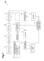
- Fig. 1 is a block diagram illustrating a configuration of a hydrogen station according to a first embodiment of the present invention.
- a hydrogen station 100 according to the first embodiment uses organic hydride as a raw material.
- the organic hydride is a hydrogenated product that is obtained by causing a reaction between aromatic hydrocarbon and hydrogen produced massively from a refinery.
- the organic hydride may be transported to the hydrogen station 100 in the form of a liquid fuel such as gasoline by a lorry or the like.
- methylcyclohexane hereinafter, referred to as "MCH" is used as the organic hydride.
- examples of the organic hydride may include a hydrogenated product of aromatic hydrocarbon such as cyclohexane, dimethyl-cyclohexane, ethyl-cyclohexane, decalin, methyl-decalin, dimethyl-decalin, and ethyl-decalin.
- the hydrogen station 100 may supply hydrogen to a fuel-cell vehicle or a hydrogen engine vehicle. Further, the hydrogen station 100 may supply organic hydride to an organic hydride vehicle.
- the hydrogen station 100 includes a vaporizer 2, a dehydrogenation reactor 3A, a cooler 4, a gas-liquid separator 6, a toluene tank 7, a shaft power drive type compressor 8, a hydrogen purifier 9, an engine 11, a MCH tank 12, a MCH pump 13, and an injector 14.
- the vaporizer 2 is a device that vaporizes the MCH supplied from the MCH tank 12 through the injector 14 by driving the MCH pump 13.
- the vaporized MCH is supplied to the dehydrogenation reactor 3 A.
- the dehydrogenation reactor 3A is a device that obtains hydrogen by causing a dehydrogenation reaction in the MCH. That is, the dehydrogenation reactor 3A is a device that extracts hydrogen from the MCH by the dehydrogenation reaction using a dehydrogenation catalyst. Since the dehydrogenation reaction is an endoergic reaction, heat is supplied to the dehydrogenation reactor 3A through a high-temperature gas from the engine 11.
- the dehydrogenation reactor 3A includes a mechanism that may exchange heat between the MCH flowing through the dehydrogenation catalyst and the high-temperature gas from the engine 11. The dehydrogenation reactor 3A supplies the extracted hydrogen gas to the cooler 4.
- the cooler 4 is a device that cools the hydrogen gas extracted from the dehydrogenation reactor 3 so that the hydrogen gas may be easily separated into a gas and a liquid.
- the cooler 4 also cools the toluene from the hydrogen purifier 9 other than the hydrogen gas from the dehydrogenation reactor 3A.
- the gas-liquid separator 6 stores a mixture of the hydrogen gas and the toluene cooled by the cooler 4 and separates the mixture into the hydrogen gas as a gas and the toluene as a liquid.
- the toluene that is separated by the gas-liquid separator 6 is collected and stored in the toluene tank 7.
- the hydrogen gas that is separated by the gas-liquid separator 6 is supplied to the shaft power drive type compressor 8.
- the shaft power drive type compressor 8 is a device that compresses the hydrogen gas obtained from the dehydrogenation reactor 3A and separated by the gas-liquid separator 6.
- the shaft power drive type compressor 8 is driven by the shaft power from the engine 11.
- the shaft power drive type compressor 8 supplies the compressed hydrogen gas to the hydrogen purifier 9.
- the shaft power drive type compressor 8 will be described later in detail.
- the hydrogen purifier 9 is a device that obtains pure hydrogen by further purifying a hydrogen gas to be supplied.
- the hydrogen gas purifying method employed by the hydrogen purifier 9 is not particularly limited and, for example, a membrane separation method or a PSA method may be employed. In a case where the hydrogen purifier 9 needs to be warmed, the hydrogen purifier may be warmed when the hydrogen purifier is provided at a position (for example, a position indicated by the two-dotted chain line) behind the dehydrogenation reactor 3A.
- the pure hydrogen that is purified by the hydrogen purifier 9 is supplied to a fuel-cell vehicle through a dispenser or the like.
- the toluene that is separated by the hydrogen purifier 9 is supplied to the cooler 4.
- the engine 11 is a device that generates shaft power and heat.
- the engine 11 is operated by fuel such as gasoline instead of electric power.
- the engine 11 is used to generate electric power inside the station by driving a generator (not illustrated) with the rotation of the rotation shaft and to drive the shaft power drive type compressor 8 by applying shaft power thereto.
- the engine 11 is used to supply heat to the dehydrogenation reactor 3A through an exhaust gas while being connected to the dehydrogenation reactor 3A through, for example, an exhaust gas pipe. Accordingly, the engine 11 may supply heat to the dehydrogenation reactor 3A by supplying the high-temperature gas to the dehydrogenation reactor 3A.
- the generator that is driven by the engine 11 may supply the generated electric power to the other devices of the hydrogen station 100 (furthermore, electric power may be supplied from an external system to the devices inside the hydrogen station 100).
- the engine 11 may be provided as a power source for driving a pump, an air compressor, and the like other than the generator.
- the high-temperature gas used for a heating purpose and generated by the engine 11 supplies heat to the dehydrogenation reactor 3A, supplies heat to the hydrogen purifier 9, and then supplies heat to the vaporizer 2. In this way, since the heat generated by the generation of power is effectively used, the energy efficiency in the entire station may be improved.
- the shaft power drive type compressor 8 is directly driven by physical power as the shaft power generated by the engine 11 instead of the drive power generated from a motor driven by electric power.
- a mechanism in which the shaft power drive type compressor 8 extracts the shaft power of the engine 11 is not particularly limited.
- the shaft power of the engine 11 may be extracted in a manner such that a pulley is attached to the front end of the shaft of the shaft power drive type compressor 8 and the pulley and the shaft of the engine are connected to each other through a belt.
- the shaft power of the engine 11 may be extracted through a crank shaft or a gear.
- the rotation of the shaft of the engine may be directly used to drive the shaft power drive type compressor 8 in a manner such that the shaft of the engine 11 directly extends so as to be common to the shaft of the shaft power drive type compressor 8.
- the shaft power drive type compressor 8 may pressurize the hydrogen gas to 0.2 to 0.5 MPa. Since the pressurization is performed in this level, a desired pressure may be sufficiently obtained by the mechanism that directly obtains the shaft power from the engine 11.
- the shaft power drive type compressor 8 for example, a vehicle engine supercharger may be used.
- the mechanisms such as the engine and the supercharger used in the vehicle may be directly applied to the hydrogen station 100.
- the engine involved mechanism in the vehicle has high efficiency, and the energy efficiency in the station may be improved by using such a highly efficient mechanism.
- a centrifugal compressor, an axial-flow compressor, and a reciprocation compressor may be employed as the shaft power drive type compressor 8.
- an auxiliary compressor that is driven by a motor may be provided in addition to the shaft power drive type compressor 8.
- the dehydrogenation reactor 3A may obtain hydrogen by causing a dehydrogenation reaction in the MCH using the heat from the engine 11. Since the engine 11 may generate not only heat, but also shaft power, the engine 11 may also drive the other devices such as a generator. In this way, when the heat of the engine 11 usable for the other purposes is used instead of using a dedicated heating device for the dehydrogenation reactor 3A, the energy efficiency in the station may be improved. Further, the shaft power drive type compressor 8 that compresses hydrogen may be driven by the shaft power of the engine 11. That is, even when a motor for driving a pressure raising compressor is not provided, the shaft power drive type compressor 8 may be directly driven by physical power as the shaft power of the engine 11 without using electric power. In a case where the direct power as the shaft power is used, the energy may be efficiently used compared to the case where the drive power is generated from the converted electric power. Accordingly, the energy efficiency in the entire station may be improved.
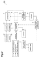
- Fig. 2 is a block diagram illustrating a hydrogen station according to a second embodiment of the present invention.
- a hydrogen station 200 according to the second embodiment is mainly different from the hydrogen station 100 according to the first embodiment in that hydrogen is obtained by a reforming reaction using hydrocarbon as a raw material.
- hydrocarbon a city gas, an LP gas, naphtha, or kerosene may be employed.
- the hydrogen station 200 includes the vaporizer 2, a steam reforming reactor 3B, the cooler 4, the gas-liquid separator 6, a water tank 21, the shaft power drive type compressor 8, the hydrogen purifier 9, the engine 11, a hydrocarbon supply unit 22, a hydrocarbon flowmeter 23, a water supply unit 24, and a water flowmeter 26. Furthermore, each of the vaporizer 2, the cooler 4, the gas-liquid separator 6, the shaft power drive type compressor 8, the hydrogen purifier 9, and the engine 11 has the same configuration as that of the hydrogen station 100 according to the first embodiment.
- the steam reforming reactor 3B is a device that obtains hydrogen by causing a steam reforming reaction in hydrocarbon.
- the steam reforming reactor 3B is a device that generates hydrogen from the hydrocarbon by the steam reforming reaction using a steam reforming catalyst. Since the steam reforming reaction is an endoergic reaction, heat is supplied to the steam reforming reactor 3B through the high-temperature gas from the engine 11.
- the steam reforming reactor 3B includes a mechanism that may exchange heat between the hydrocarbon flowing through the steam reforming catalyst and the high-temperature gas from the engine 11.
- the steam reforming reactor 3B supplies the extracted hydrogen gas to the cooler 4.
- the hydrogen gas is supplied to the gas-liquid separator 6 through the cooler 4 so as to be separated into a hydrogen gas and water, and the water is stored in the water tank 21.
- the steam reforming reactor 3B may obtain hydrogen by causing the steam reforming reaction in hydrocarbon using the heat from the engine 11. Since the engine 11 may generate not only heat, but also shaft power, the engine 11 may also drive the other devices such as a generator. In this way, since the heat of the engine 11 usable for the other purposes is used instead of a dedicated heating device for the steam reforming reactor 3B, the energy efficiency in the station may be improved. Further, the shaft power drive type compressor 8 that compresses hydrogen may be driven by the shaft power of the engine 11. That is, even when a motor for driving a pressure raising compressor is not provided, the shaft power drive type compressor 8 may be directly driven by physical power as the shaft power of the engine 11 without using electric power. In a case where the direct power as the shaft power is used, the energy may be efficiently used compared to the case where the drive power is generated from the converted electric power. Accordingly, the energy efficiency in the entire station may be improved.
- the shaft power generation unit is the engine, but any unit capable of supplying heat and generating shaft power may be used.
- a turbine may be also used.
- a daily activation stop operation such as a daily start and shut-down operation as an operation method supposed in the hydrogen station or a load variation operation capable of changing a hydrogen generation amount in response to a demanded hydrogen amount may be easily handled.
- the present invention may be applied to a hydrogen station that supplies hydrogen.
Landscapes
- Chemical & Material Sciences (AREA)
- Organic Chemistry (AREA)
- Chemical Kinetics & Catalysis (AREA)
- Health & Medical Sciences (AREA)
- General Health & Medical Sciences (AREA)
- Engineering & Computer Science (AREA)
- Combustion & Propulsion (AREA)
- Inorganic Chemistry (AREA)
- Hydrogen, Water And Hydrids (AREA)
- Fuel Cell (AREA)
- Filling Or Discharging Of Gas Storage Vessels (AREA)
Abstract
Description
- The present invention relates to a hydrogen station that supplies hydrogen.
- As a hydrogen station of the related art, for example, a hydrogen station disclosed in Patent Literature 1 is known. The hydrogen station of Patent Literature 1 includes a storage tank that stores organic hydride, a reactor that obtains hydrogen by causing a dehydrogenation reaction in the organic hydride supplied from the storage tank, a hydrogen purifying device that purifies the hydrogen obtained by the reactor, and a heating device that heats the reactor. As the heating device, a combustion burner is used.
- Patent Literature 1: Japanese Patent Application Laid-Open No.
2004-256326 - However, in the above-described hydrogen station, the combustion burner is provided so as to heat the reactor. The combustion burner is provided to heat only the reactor, and is not used for the other purposes inside the station. As a result, the energy is not effectively used in the entire station. Meanwhile, in the hydrogen station, a hydrogen purifying process needs to be performed on the hydrogen causing a reaction in the reactor. Since a hydrogen pressure raising process is needed at the step earlier than the hydrogen purifying process, a compressor that compresses the hydrogen obtained by the reactor is needed. Further, since a motor that is driven by electric power is provided in order to drive the compressor, separate energy is needed. As described above, the related art has a problem in that the energy efficiency is low in the entire station.
- Therefore, an object of the present invention is to provide a hydrogen station capable of improving energy efficiency in an entire station.
- According to an embodiment of the present invention, there is provided a hydrogen station that supplies hydrogen, including: a shaft power generation unit that generates shaft power and heat; a reactor that obtains hydrogen by causing a reaction in a raw material using the heat supplied from the shaft power generation unit; and a compressor that compresses the hydrogen obtained by the reactor, wherein the shaft power generation unit drives the other devices and drives the compressor by applying the shaft power thereto.
- In the hydrogen station according to the embodiment of the present invention, hydrogen may be obtained in a manner such that the reactor causes a reaction in the raw material by using the heat from the shaft power generation unit. Since the shaft power generation unit may generate not only heat, but also shaft power, the shaft power generation unit may drive the other devices. In this way, since the heat of the shaft power generation unit also usable for the other purposes is used to heat the reactor instead of using a dedicated heating device for the reactor, the energy efficiency in the station may be improved. Further, the shaft power generation unit may drive the compressor compressing hydrogen by applying the shaft power thereto. That is, even when a motor for driving the compressor is not provided, the compressor may be driven by directly using physical power as the shaft power of the shaft power generation unit without using electric power. Accordingly, the energy efficiency in the entire station may be improved.
- In the hydrogen station, the shaft power generation unit may be an engine. As the engine, a spark-ignition-type engine or a diesel engine is considered, but any system capable of generating shaft power and heat may be used. When the engine is used, a change in operation condition such as an activation stop or a load variation may be easily handled compared to a turbine and the like.
- In the hydrogen station, the compressor may be configured as a vehicle engine supercharger. A mechanism that is used in a vehicle has extremely high efficiency, and the energy efficiency in the entire station may be improved by using such a mechanism.
- In the hydrogen station, for example, the raw material is organic hydride, and the reactor may obtain hydrogen by causing a dehydrogenation reaction in the organic hydride. Alternatively, the raw material is hydrocarbon, and the reactor may obtain hydrogen by causing a reforming reaction in the hydrocarbon.
- According to the present invention, the energy efficiency may be improved in the entire station.
-
-
Fig. 1 is a block diagram illustrating a configuration of a hydrogen station according to a first embodiment of the present invention. -
Fig. 2 is a block diagram illustrating a configuration of a hydrogen station according to a second embodiment of the present invention. - Hereinafter, preferred embodiments of the present invention will be described in detail with reference to the drawings.
-
Fig. 1 is a block diagram illustrating a configuration of a hydrogen station according to a first embodiment of the present invention. Ahydrogen station 100 according to the first embodiment uses organic hydride as a raw material. The organic hydride is a hydrogenated product that is obtained by causing a reaction between aromatic hydrocarbon and hydrogen produced massively from a refinery. The organic hydride may be transported to thehydrogen station 100 in the form of a liquid fuel such as gasoline by a lorry or the like. In this embodiment, methylcyclohexane (hereinafter, referred to as "MCH") is used as the organic hydride. In addition, examples of the organic hydride may include a hydrogenated product of aromatic hydrocarbon such as cyclohexane, dimethyl-cyclohexane, ethyl-cyclohexane, decalin, methyl-decalin, dimethyl-decalin, and ethyl-decalin. Thehydrogen station 100 may supply hydrogen to a fuel-cell vehicle or a hydrogen engine vehicle. Further, thehydrogen station 100 may supply organic hydride to an organic hydride vehicle. - As illustrated in
Fig. 1 , thehydrogen station 100 according to this embodiment includes avaporizer 2, adehydrogenation reactor 3A, a cooler 4, a gas-liquid separator 6, atoluene tank 7, a shaft powerdrive type compressor 8, ahydrogen purifier 9, anengine 11, aMCH tank 12, aMCH pump 13, and aninjector 14. - The
vaporizer 2 is a device that vaporizes the MCH supplied from theMCH tank 12 through theinjector 14 by driving theMCH pump 13. The vaporized MCH is supplied to thedehydrogenation reactor 3 A. - The
dehydrogenation reactor 3A is a device that obtains hydrogen by causing a dehydrogenation reaction in the MCH. That is, thedehydrogenation reactor 3A is a device that extracts hydrogen from the MCH by the dehydrogenation reaction using a dehydrogenation catalyst. Since the dehydrogenation reaction is an endoergic reaction, heat is supplied to thedehydrogenation reactor 3A through a high-temperature gas from theengine 11. Thedehydrogenation reactor 3A includes a mechanism that may exchange heat between the MCH flowing through the dehydrogenation catalyst and the high-temperature gas from theengine 11. Thedehydrogenation reactor 3A supplies the extracted hydrogen gas to the cooler 4. - The cooler 4 is a device that cools the hydrogen gas extracted from the dehydrogenation reactor 3 so that the hydrogen gas may be easily separated into a gas and a liquid. The cooler 4 also cools the toluene from the
hydrogen purifier 9 other than the hydrogen gas from thedehydrogenation reactor 3A. The gas-liquid separator 6 stores a mixture of the hydrogen gas and the toluene cooled by the cooler 4 and separates the mixture into the hydrogen gas as a gas and the toluene as a liquid. The toluene that is separated by the gas-liquid separator 6 is collected and stored in thetoluene tank 7. The hydrogen gas that is separated by the gas-liquid separator 6 is supplied to the shaft powerdrive type compressor 8. - The shaft power
drive type compressor 8 is a device that compresses the hydrogen gas obtained from thedehydrogenation reactor 3A and separated by the gas-liquid separator 6. The shaft powerdrive type compressor 8 is driven by the shaft power from theengine 11. The shaft powerdrive type compressor 8 supplies the compressed hydrogen gas to thehydrogen purifier 9. The shaft powerdrive type compressor 8 will be described later in detail. - The
hydrogen purifier 9 is a device that obtains pure hydrogen by further purifying a hydrogen gas to be supplied. The hydrogen gas purifying method employed by thehydrogen purifier 9 is not particularly limited and, for example, a membrane separation method or a PSA method may be employed. In a case where thehydrogen purifier 9 needs to be warmed, the hydrogen purifier may be warmed when the hydrogen purifier is provided at a position (for example, a position indicated by the two-dotted chain line) behind thedehydrogenation reactor 3A. The pure hydrogen that is purified by thehydrogen purifier 9 is supplied to a fuel-cell vehicle through a dispenser or the like. The toluene that is separated by thehydrogen purifier 9 is supplied to the cooler 4. - The
engine 11 is a device that generates shaft power and heat. Theengine 11 is operated by fuel such as gasoline instead of electric power. Theengine 11 is used to generate electric power inside the station by driving a generator (not illustrated) with the rotation of the rotation shaft and to drive the shaft powerdrive type compressor 8 by applying shaft power thereto. Further, theengine 11 is used to supply heat to thedehydrogenation reactor 3A through an exhaust gas while being connected to thedehydrogenation reactor 3A through, for example, an exhaust gas pipe. Accordingly, theengine 11 may supply heat to thedehydrogenation reactor 3A by supplying the high-temperature gas to thedehydrogenation reactor 3A. Further, the generator that is driven by theengine 11 may supply the generated electric power to the other devices of the hydrogen station 100 (furthermore, electric power may be supplied from an external system to the devices inside the hydrogen station 100). Theengine 11 may be provided as a power source for driving a pump, an air compressor, and the like other than the generator. - Further, the high-temperature gas used for a heating purpose and generated by the
engine 11 supplies heat to thedehydrogenation reactor 3A, supplies heat to thehydrogen purifier 9, and then supplies heat to thevaporizer 2. In this way, since the heat generated by the generation of power is effectively used, the energy efficiency in the entire station may be improved. - The shaft power
drive type compressor 8 is directly driven by physical power as the shaft power generated by theengine 11 instead of the drive power generated from a motor driven by electric power. A mechanism in which the shaft powerdrive type compressor 8 extracts the shaft power of theengine 11 is not particularly limited. For example, the shaft power of theengine 11 may be extracted in a manner such that a pulley is attached to the front end of the shaft of the shaft powerdrive type compressor 8 and the pulley and the shaft of the engine are connected to each other through a belt. Alternatively, the shaft power of theengine 11 may be extracted through a crank shaft or a gear. Alternatively, the rotation of the shaft of the engine may be directly used to drive the shaft powerdrive type compressor 8 in a manner such that the shaft of theengine 11 directly extends so as to be common to the shaft of the shaft powerdrive type compressor 8. The shaft powerdrive type compressor 8 may pressurize the hydrogen gas to 0.2 to 0.5 MPa. Since the pressurization is performed in this level, a desired pressure may be sufficiently obtained by the mechanism that directly obtains the shaft power from theengine 11. - As the shaft power
drive type compressor 8, for example, a vehicle engine supercharger may be used. When the supercharger is used, the mechanisms such as the engine and the supercharger used in the vehicle may be directly applied to thehydrogen station 100. The engine involved mechanism in the vehicle has high efficiency, and the energy efficiency in the station may be improved by using such a highly efficient mechanism. In addition, as the shaft powerdrive type compressor 8, a centrifugal compressor, an axial-flow compressor, and a reciprocation compressor may be employed. - Furthermore, an auxiliary compressor that is driven by a motor may be provided in addition to the shaft power
drive type compressor 8. However, it is desirable to provide only the shaft powerdrive type compressor 8 in that the driving portion in the station may be decreased in number. - Next, an operation and an effect of the
hydrogen station 100 according to the embodiment will be described. - In the
hydrogen station 100 according to this embodiment, thedehydrogenation reactor 3A may obtain hydrogen by causing a dehydrogenation reaction in the MCH using the heat from theengine 11. Since theengine 11 may generate not only heat, but also shaft power, theengine 11 may also drive the other devices such as a generator. In this way, when the heat of theengine 11 usable for the other purposes is used instead of using a dedicated heating device for thedehydrogenation reactor 3A, the energy efficiency in the station may be improved. Further, the shaft powerdrive type compressor 8 that compresses hydrogen may be driven by the shaft power of theengine 11. That is, even when a motor for driving a pressure raising compressor is not provided, the shaft powerdrive type compressor 8 may be directly driven by physical power as the shaft power of theengine 11 without using electric power. In a case where the direct power as the shaft power is used, the energy may be efficiently used compared to the case where the drive power is generated from the converted electric power. Accordingly, the energy efficiency in the entire station may be improved. -
Fig. 2 is a block diagram illustrating a hydrogen station according to a second embodiment of the present invention. Ahydrogen station 200 according to the second embodiment is mainly different from thehydrogen station 100 according to the first embodiment in that hydrogen is obtained by a reforming reaction using hydrocarbon as a raw material. - As the hydrocarbon, a city gas, an LP gas, naphtha, or kerosene may be employed.
- As illustrated in
Fig. 2 , thehydrogen station 200 according to this embodiment includes thevaporizer 2, asteam reforming reactor 3B, the cooler 4, the gas-liquid separator 6, awater tank 21, the shaft powerdrive type compressor 8, thehydrogen purifier 9, theengine 11, ahydrocarbon supply unit 22, ahydrocarbon flowmeter 23, awater supply unit 24, and awater flowmeter 26. Furthermore, each of thevaporizer 2, the cooler 4, the gas-liquid separator 6, the shaft powerdrive type compressor 8, thehydrogen purifier 9, and theengine 11 has the same configuration as that of thehydrogen station 100 according to the first embodiment. - The
steam reforming reactor 3B is a device that obtains hydrogen by causing a steam reforming reaction in hydrocarbon. Thesteam reforming reactor 3B is a device that generates hydrogen from the hydrocarbon by the steam reforming reaction using a steam reforming catalyst. Since the steam reforming reaction is an endoergic reaction, heat is supplied to thesteam reforming reactor 3B through the high-temperature gas from theengine 11. Thesteam reforming reactor 3B includes a mechanism that may exchange heat between the hydrocarbon flowing through the steam reforming catalyst and the high-temperature gas from theengine 11. Thesteam reforming reactor 3B supplies the extracted hydrogen gas to the cooler 4. - The hydrogen gas is supplied to the gas-
liquid separator 6 through the cooler 4 so as to be separated into a hydrogen gas and water, and the water is stored in thewater tank 21. - In the
hydrogen station 200 according to this embodiment, thesteam reforming reactor 3B may obtain hydrogen by causing the steam reforming reaction in hydrocarbon using the heat from theengine 11. Since theengine 11 may generate not only heat, but also shaft power, theengine 11 may also drive the other devices such as a generator. In this way, since the heat of theengine 11 usable for the other purposes is used instead of a dedicated heating device for thesteam reforming reactor 3B, the energy efficiency in the station may be improved. Further, the shaft powerdrive type compressor 8 that compresses hydrogen may be driven by the shaft power of theengine 11. That is, even when a motor for driving a pressure raising compressor is not provided, the shaft powerdrive type compressor 8 may be directly driven by physical power as the shaft power of theengine 11 without using electric power. In a case where the direct power as the shaft power is used, the energy may be efficiently used compared to the case where the drive power is generated from the converted electric power. Accordingly, the energy efficiency in the entire station may be improved. - The present invention is not limited to the above-described embodiments.
- An example has been described in which the shaft power generation unit is the engine, but any unit capable of supplying heat and generating shaft power may be used. For example, a turbine may be also used. Here, in a case where the engine is used instead of the turbine, there is a merit that a daily activation stop operation such as a daily start and shut-down operation as an operation method supposed in the hydrogen station or a load variation operation capable of changing a hydrogen generation amount in response to a demanded hydrogen amount may be easily handled.
- The present invention may be applied to a hydrogen station that supplies hydrogen.
-
- 3A
- dehydrogenation reactor (reaction unit)
- 3B
- steam reforming reactor (reaction unit)
- 8
- shaft power drive type compressor (compressor)
- 9
- hydrogen purifier
- 11
- engine (shaft power generation unit)
Claims (5)
- A hydrogen station that supplies hydrogen, comprising:a shaft power generation unit that generates shaft power and heat;a reactor that obtains hydrogen by causing a reaction in a raw material using the heat supplied from the shaft power generation unit; anda compressor that compresses the hydrogen obtained by the reactor,wherein the shaft power generation unit drives the other devices and drives the compressor by applying the shaft power thereto.
- The hydrogen station according to claim 1,
wherein the shaft power generation unit is an engine. - The hydrogen station according to claim 2,
wherein the compressor is configured as a vehicle engine supercharger. - The hydrogen station according to any one of claims 1 to 3,
wherein the raw material is organic hydride, and
wherein the reactor obtains hydrogen by causing a dehydrogenation reaction in the organic hydride. - The hydrogen station according to any one of claims 1 to 3,
wherein the raw material is hydrocarbon, and
wherein the reactor obtains hydrogen by causing a reforming reaction in the hydrocarbon.
Applications Claiming Priority (2)
| Application Number | Priority Date | Filing Date | Title |
|---|---|---|---|
| JP2011227095A JP2013087820A (en) | 2011-10-14 | 2011-10-14 | Hydrogen station |
| PCT/JP2012/076337 WO2013054851A1 (en) | 2011-10-14 | 2012-10-11 | Hydrogen station |
Publications (2)
| Publication Number | Publication Date |
|---|---|
| EP2767747A1 true EP2767747A1 (en) | 2014-08-20 |
| EP2767747A4 EP2767747A4 (en) | 2015-07-22 |
Family
ID=48081902
Family Applications (1)
| Application Number | Title | Priority Date | Filing Date |
|---|---|---|---|
| EP12840092.6A Withdrawn EP2767747A4 (en) | 2011-10-14 | 2012-10-11 | HYDROGEN STATION |
Country Status (5)
| Country | Link |
|---|---|
| US (1) | US20140348714A1 (en) |
| EP (1) | EP2767747A4 (en) |
| JP (1) | JP2013087820A (en) |
| CN (1) | CN103958955A (en) |
| WO (1) | WO2013054851A1 (en) |
Families Citing this family (8)
| Publication number | Priority date | Publication date | Assignee | Title |
|---|---|---|---|---|
| JP5632050B1 (en) * | 2013-07-12 | 2014-11-26 | 株式会社辰巳菱機 | Dehydrogenation system |
| KR101684767B1 (en) * | 2015-02-11 | 2016-12-08 | 대우조선해양 주식회사 | Hydrogen supply apparatus and method of submarine using organic chemical hydride |
| KR101670174B1 (en) * | 2015-06-05 | 2016-10-27 | 대우조선해양 주식회사 | Hydrogen supply system of submarine and management method thereof |
| KR101684791B1 (en) * | 2015-07-09 | 2016-12-08 | 대우조선해양 주식회사 | Hydrogen supply system and method of submarine |
| CN106090599A (en) * | 2016-06-28 | 2016-11-09 | 沈军 | Hydrogen energy supply chain |
| CN106704815B (en) * | 2016-11-20 | 2020-01-17 | 硕橙(厦门)科技有限公司 | Self-supporting hydrogenation station utilizing renewable energy |
| JP7163853B2 (en) * | 2019-04-11 | 2022-11-01 | 株式会社豊田自動織機 | Reformer system and engine system |
| EP4324560A4 (en) * | 2021-04-16 | 2025-06-25 | Chiyoda Corporation | HYDROGEN STATION AND METHOD FOR GENERATING HYDROGEN |
Family Cites Families (15)
| Publication number | Priority date | Publication date | Assignee | Title |
|---|---|---|---|---|
| JP2000080927A (en) * | 1998-09-04 | 2000-03-21 | Toshiba Corp | Gas turbine system |
| JP2004017701A (en) * | 2002-06-12 | 2004-01-22 | Babcock Hitachi Kk | Hydrogen station and reformer |
| JP4279546B2 (en) * | 2002-12-20 | 2009-06-17 | 千代田化工建設株式会社 | High pressure hydrogen supply system |
| JP4305899B2 (en) | 2003-02-24 | 2009-07-29 | 株式会社フレイン・エナジー | Hydrogen generation and storage equipment |
| CN1805898A (en) * | 2003-04-11 | 2006-07-19 | 詹姆斯·H·拜尔 | Method and apparatus for storing and transporting hydrogen |
| JP4272922B2 (en) * | 2003-05-26 | 2009-06-03 | 本田技研工業株式会社 | Pure hydrogen production equipment |
| US7384620B2 (en) * | 2003-07-10 | 2008-06-10 | General Electric Company | Method and system for producing hydrogen by reforming hydrogen-containing gas |
| US20050048345A1 (en) * | 2003-09-03 | 2005-03-03 | Meacham G.B. Kirby | Hybrid fuel cell system with internal combustion reforming |
| JP2006248814A (en) * | 2005-03-09 | 2006-09-21 | Hitachi Ltd | Hydrogen supply apparatus and hydrogen supply method |
| AT502478B1 (en) * | 2005-10-31 | 2007-04-15 | Electrovac Ag | Use of a procedure to produce hydrogen and nano-carbon comprising providing hydrocarbon-containing feed gas into a reformer, contacting feed gas with catalyst and converting to hydrogen and solid carbon, to produce hydrogen-containing gas |
| JP4737023B2 (en) * | 2006-10-04 | 2011-07-27 | 株式会社日立製作所 | Hydrogen engine system |
| CN100534840C (en) * | 2006-07-26 | 2009-09-02 | 北京飞驰绿能电源技术有限责任公司 | Hydrogen generating and refilling system and method capable of refilling hydrogen fast |
| JP5159800B2 (en) * | 2008-02-13 | 2013-03-13 | 勝 市川 | Hydrogen supply device for internal combustion engine and operation method of internal combustion engine |
| JP5174602B2 (en) * | 2008-09-30 | 2013-04-03 | 株式会社日立製作所 | Hydrogen storage system |
| JP5575549B2 (en) * | 2010-05-31 | 2014-08-20 | 株式会社日立製作所 | Energy generation system |
-
2011
- 2011-10-14 JP JP2011227095A patent/JP2013087820A/en active Pending
-
2012
- 2012-10-11 CN CN201280050583.8A patent/CN103958955A/en active Pending
- 2012-10-11 US US14/351,010 patent/US20140348714A1/en not_active Abandoned
- 2012-10-11 WO PCT/JP2012/076337 patent/WO2013054851A1/en not_active Ceased
- 2012-10-11 EP EP12840092.6A patent/EP2767747A4/en not_active Withdrawn
Also Published As
| Publication number | Publication date |
|---|---|
| WO2013054851A1 (en) | 2013-04-18 |
| EP2767747A4 (en) | 2015-07-22 |
| JP2013087820A (en) | 2013-05-13 |
| CN103958955A (en) | 2014-07-30 |
| US20140348714A1 (en) | 2014-11-27 |
Similar Documents
| Publication | Publication Date | Title |
|---|---|---|
| US20140348714A1 (en) | Hydrogen station | |
| JP6189500B2 (en) | System and method for high efficiency power generation using nitrogen gas working fluid | |
| US6832485B2 (en) | Method of and apparatus for producing power using a reformer and gas turbine unit | |
| EP4506549A2 (en) | Cracking and separation of ammonia fuel | |
| US20140356738A1 (en) | Ammonia based system to prepare and utilize hydrogen to produce electricity | |
| KR20200049933A (en) | Floating platform | |
| US20120067304A1 (en) | Economical hybrid fuel | |
| US9583776B2 (en) | Sweep membrane separator and fuel processing systems | |
| JPWO2009101715A1 (en) | Hydrogen supply device for internal combustion engine and operation method of internal combustion engine | |
| RU2407586C2 (en) | Device and method of producing hydrogen gas by hydrocarbon fuel dehydrogenation | |
| JP7713864B2 (en) | Gas Turbine Systems | |
| JP2009503363A (en) | Generator | |
| US20070122339A1 (en) | Methods and apparatus for hydrogen production | |
| US20050242588A1 (en) | Integrated fuel cell and additive gas supply system for a power generation system including a combustion engine | |
| CN1644906A (en) | Pulse detonation power system and plant with fuel preconditioning | |
| CN107867674A (en) | Method and apparatus for steam reformation | |
| TR201802811T4 (en) | Fuel System for a Moving Machine. | |
| JP2004017701A (en) | Hydrogen station and reformer | |
| US11427468B2 (en) | Integrated hydrogen generator and compressor with related method | |
| JP2005337214A (en) | Heavy oil reforming gas turbine power generation system using high temperature and high pressure water | |
| EP2904256B1 (en) | Hydrogen generation out of water | |
| US20240295041A1 (en) | Synthetic fuel manufacturing system | |
| JP2003183006A (en) | Hydrogen production equipment | |
| US20220403773A1 (en) | Method and apparatus for storing energy | |
| JP2006344592A (en) | FUEL CELL SYSTEM AND WATER MANUFACTURING METHOD FOR FUEL CELL SYSTEM |
Legal Events
| Date | Code | Title | Description |
|---|---|---|---|
| PUAI | Public reference made under article 153(3) epc to a published international application that has entered the european phase |
Free format text: ORIGINAL CODE: 0009012 |
|
| 17P | Request for examination filed |
Effective date: 20140423 |
|
| AK | Designated contracting states |
Kind code of ref document: A1 Designated state(s): AL AT BE BG CH CY CZ DE DK EE ES FI FR GB GR HR HU IE IS IT LI LT LU LV MC MK MT NL NO PL PT RO RS SE SI SK SM TR |
|
| DAX | Request for extension of the european patent (deleted) | ||
| RA4 | Supplementary search report drawn up and despatched (corrected) |
Effective date: 20150622 |
|
| RIC1 | Information provided on ipc code assigned before grant |
Ipc: C01B 3/38 20060101ALI20150616BHEP Ipc: B01J 12/00 20060101ALI20150616BHEP Ipc: C01B 3/26 20060101ALI20150616BHEP Ipc: F17C 5/06 20060101AFI20150616BHEP |
|
| STAA | Information on the status of an ep patent application or granted ep patent |
Free format text: STATUS: THE APPLICATION HAS BEEN WITHDRAWN |
|
| 18W | Application withdrawn |
Effective date: 20151221 |