EP2767656B1 - Lock for a door or door wing - Google Patents
Lock for a door or door wing Download PDFInfo
- Publication number
- EP2767656B1 EP2767656B1 EP14154921.2A EP14154921A EP2767656B1 EP 2767656 B1 EP2767656 B1 EP 2767656B1 EP 14154921 A EP14154921 A EP 14154921A EP 2767656 B1 EP2767656 B1 EP 2767656B1
- Authority
- EP
- European Patent Office
- Prior art keywords
- cylinder
- seats
- cams
- openings
- stem
- Prior art date
- Legal status (The legal status is an assumption and is not a legal conclusion. Google has not performed a legal analysis and makes no representation as to the accuracy of the status listed.)
- Active
Links
- 230000000295 complement effect Effects 0.000 claims description 6
- 230000008878 coupling Effects 0.000 claims description 5
- 238000010168 coupling process Methods 0.000 claims description 5
- 238000005859 coupling reaction Methods 0.000 claims description 5
- 230000003993 interaction Effects 0.000 claims description 3
- 230000008901 benefit Effects 0.000 description 4
- 238000004519 manufacturing process Methods 0.000 description 3
- 230000004913 activation Effects 0.000 description 2
- 230000009849 deactivation Effects 0.000 description 2
- 230000000670 limiting effect Effects 0.000 description 2
- 230000007246 mechanism Effects 0.000 description 2
- 230000008859 change Effects 0.000 description 1
- 239000000463 material Substances 0.000 description 1
- 230000003340 mental effect Effects 0.000 description 1
- 239000002184 metal Substances 0.000 description 1
- 230000004048 modification Effects 0.000 description 1
- 238000012986 modification Methods 0.000 description 1
Images


Classifications
-
- E—FIXED CONSTRUCTIONS
- E05—LOCKS; KEYS; WINDOW OR DOOR FITTINGS; SAFES
- E05B—LOCKS; ACCESSORIES THEREFOR; HANDCUFFS
- E05B15/00—Other details of locks; Parts for engagement by bolts of fastening devices
- E05B15/14—Tumblers
-
- E—FIXED CONSTRUCTIONS
- E05—LOCKS; KEYS; WINDOW OR DOOR FITTINGS; SAFES
- E05B—LOCKS; ACCESSORIES THEREFOR; HANDCUFFS
- E05B47/00—Operating or controlling locks or other fastening devices by electric or magnetic means
- E05B47/0038—Operating or controlling locks or other fastening devices by electric or magnetic means using permanent magnets
- E05B47/0042—Operating or controlling locks or other fastening devices by electric or magnetic means using permanent magnets with rotary magnet tumblers
-
- E—FIXED CONSTRUCTIONS
- E05—LOCKS; KEYS; WINDOW OR DOOR FITTINGS; SAFES
- E05B—LOCKS; ACCESSORIES THEREFOR; HANDCUFFS
- E05B63/00—Locks or fastenings with special structural characteristics
- E05B63/0065—Operating modes; Transformable to different operating modes
-
- E—FIXED CONSTRUCTIONS
- E05—LOCKS; KEYS; WINDOW OR DOOR FITTINGS; SAFES
- E05C—BOLTS OR FASTENING DEVICES FOR WINGS, SPECIALLY FOR DOORS OR WINDOWS
- E05C3/00—Fastening devices with bolts moving pivotally or rotatively
- E05C3/02—Fastening devices with bolts moving pivotally or rotatively without latching action
- E05C3/04—Fastening devices with bolts moving pivotally or rotatively without latching action with operating handle or equivalent member rigid with the bolt
- E05C3/041—Fastening devices with bolts moving pivotally or rotatively without latching action with operating handle or equivalent member rigid with the bolt rotating about an axis perpendicular to the surface on which the fastener is mounted
- E05C3/042—Fastening devices with bolts moving pivotally or rotatively without latching action with operating handle or equivalent member rigid with the bolt rotating about an axis perpendicular to the surface on which the fastener is mounted the handle being at one side, the bolt at the other side or inside the wing
-
- Y—GENERAL TAGGING OF NEW TECHNOLOGICAL DEVELOPMENTS; GENERAL TAGGING OF CROSS-SECTIONAL TECHNOLOGIES SPANNING OVER SEVERAL SECTIONS OF THE IPC; TECHNICAL SUBJECTS COVERED BY FORMER USPC CROSS-REFERENCE ART COLLECTIONS [XRACs] AND DIGESTS
- Y10—TECHNICAL SUBJECTS COVERED BY FORMER USPC
- Y10T—TECHNICAL SUBJECTS COVERED BY FORMER US CLASSIFICATION
- Y10T70/00—Locks
- Y10T70/70—Operating mechanism
- Y10T70/7441—Key
- Y10T70/7486—Single key
Definitions
- the present invention relates to a lock.
- locks also termed cam locks
- cam locks which are substantially constituted by a cam or plate made of mental, fixed to a pivot, which rotates together with the key; the metal plate usually moves by 90° or 180° and makes it possible to ensure the locking for example of a door;
- these locks can use cylindrical pin tumblers of different lengths arranged in a circle and moved into position by a tubular key, or are provided with a row of discs with different profiles, which must be aligned by the correct key in order to open the lock, and in this case the key used is of the flat type.
- This known type of lock is structurally very simple and therefore is subject to break-ins.
- the "Series 35" lock by the British company CAMLOCK SYSTEM Ltd, headquartered in 3 Park View, Compton Industrial Estate, Eastbourne, East Hampshire, is known which comprises a cylinder provided with an anti-drill center post to which said lever is keyed and which can be activated by means of an adapted key provided with radial elements that can be inserted in complementary shaped seats or slots provided in a cover that can be screwed onto said cylinder.
- FR2791379A1 discloses a lock comprising a mounting base on a support, such as a door leaf, a locking mechanism and a member that controls the locking mechanism mounted in connection with the latter through the base, in order that the body may be changed.
- the aim of the present invention is to solve the highlighted technical problems, eliminating the drawbacks of the cited background art, by devising a lock of the cam type that allows the hindering of tampering attempts and has low manufacturing, stocking and transport costs.
- an object of the invention is to provide a lock that makes it possible to prevent a burglar from achieving a condition of direct access to the cylinder.
- Another object is to provide a lock that is structurally simple and has low manufacturing costs.
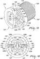
- the reference numeral 1 designates a lock, which comprises a cylinder 2, fixed to a door or door wing (not shown), which has a T-shaped configuration whose first stem 3 has an external thread 4 and whose first head 5 has a cylindrical shape and a first seat 6, axially to which a through hole 7 is provided.
- a pivot 8 is arranged rotatably and coaxially in the first seat 6 and at the hole 7, such pivot 8 being T-shaped so as to form a second cylindrical stem 9, which acts rotatably in said hole 7 and which, when installed, protrudes with its end 10 beyond the lower surface 11 of the first stem 3 of the cylinder 2.
- the second stem 9 is kept rotatably associated, without the possibility of disconnection, with the cylinder 2 by means of an elastic key 12, which is omega-shaped and can be associated at an annular groove 13 that is provided in said first stem 9 and is adjacent to said end 10.
- the pivot 8 has, moreover, a second flat head 14, which acts rotatably within the first seat 6, the second head 14 having, in plan view, a circular shape with two recesses 15a, 15b obtained along two parallel chords.
- a lever 17 is keyed to the end 10 of the second stem 9, which has an adapted pair of mutually parallel bevels 16a, 16b and is adapted to allow the closing of said door or door wing to a jamb.
- a separate body 18 can be keyed detachably at said second head 14 of said pivot 8 and is provided with magnetic means 19 for the temporary locking of the rotation of said body 18 with respect to said cylinder 2.
- the cylinder 2 is fixed to a door or door wing by means of an adapted ring 20 that can be associated rotatably with said external thread 4 of the first stem 3 of said cylinder 2.
- the body 18 is constituted by a disc 21 that has, on a front surface 22 that is directed away from the cylinder 2, a second seat 23, which has a preferably square plan shape with rounded corners and within which it is possible to arrange selectively a complementary shaped magnetic key 24 that contains at least one magnet.
- Grooves 25 are provided in the perimetric edge of the disc 21 and are adapted to constitute grip means for the user, who can thus impart a desired rotation to the disc 21.
- a third cylindrical stem 26 protrudes on the side that is opposite to the front surface 22 of the disc 21 and has, in its surface 27 directed toward the pivot 8, in the particular embodiment shown, four circular third seats or cavities 28a, 28b, 28c, 28d for complementary shaped cams 29a, 29b, 29c, 29d, that can be associated rotatably therewith.
- the body 18 can be associated slidingly and detachably with the second head 14 and has, for this purpose, an adapted pair of protrusions 15c, 15d, which are preferably crescent-shaped, protrude so as to be mutually opposite from the surface 27, and have such dimensions and such an arrangement that they interact slidingly with the recesses 15a, 15b, as shown in Figures 7 and 8 , so as to achieve temporary interconnection with the second head 14.
- the height of the flat base 15e, 15f of the protrusions 15c, 15d in fact is substantially equal to the width of the recesses 15a, 15b, while the distance between the protrusions 15c, 15d is substantially equal to the distance between the recesses 15a, 15b.
- the coupling occurs by means of a dovetail connection, the surfaces of the recesses 15a, 15b and of the protrusions 15c, 15d being inclined.
- the third seats or cavities are advantageously arranged with the center at the corners of a polygon, constituted, in the particular embodiment, by a square.
- the number of the four third seats or cavities may be larger or smaller than four; advantageously, the center of the four third seats or cavities is arranged at a polygon having an equal number of sides; thus, if there are three seats the polygon will be a triangle, if there are five it will be a pentagon, and so forth.
- a pin 31 is arrangeable within each one of said through openings 30a, 30b, 30c, 30d and has advantageously an approximately hemispherical head.
- pins 31 are slightly longer than the depth of the respective through openings 30a, 30b, 30c, 30d and have the function of locking temporarily, when they protrude with their first end 32 beyond the perimetric edge 33 of the third stem 26, the rotation of said cylinder 2, since the first ends are arranged temporarily within adapted fourth seats 34 that are provided axially to the internal lateral surface 35 of the first head 5 of the cylinder 2.
- Each one of the through openings 30a, 30b, 30c, 30d has an end section, directed away from the cylinder 5, that is narrow, so as to form a discontinuity that is adapted to act as an abutment for an end of an elastically deformable element, such as a spring 36, which with the opposite end abuts against the base of the first end 32 of the pins 31.
- an elastically deformable element such as a spring 36
- the springs 36 force the first end 32 of the pins 31 to protrude from the through openings 30a, 30b, 30c, 30d in order to allow the first ends 32 to be arranged, when they are in front of them, in fourth seats 34 of the cylinder 2.
- Each one of the pins 31 has, at the end opposite to the first end 32, a second end 37, which, in the condition in which the first ends 32 are arranged within the fourth seats 34 of the cylinder 2, is completely inserted in one of the through openings 30a, 30b, 30c, 30d, without therefore protruding from them.
- the length of the pins is therefore such that either the first end 32 or the second end 37 protrude out of the through openings 30a, 30b, 30c, 30d.
- cams 29a, 29b, 29c, 29d are kept in position by means of adapted central axes or pivots 38 that protrude from them and are supported by adapted discs 39 that are arranged so as to close the third seats or cavities 28a, 28b, 28c, 28d, so as to prevent also the exit of the cams from the first seats.
- the discs 39 face the adjacent flat surface of the second head 14.
- Each one of the cams 29a, 29b, 29c, 29d is substantially cylindrical and at least one first hollow 40 is provided, along a generatrix, on their lateral surface, is preferably but not necessarily approximately semicircular in plan view, and is such as to allow the temporary arrangement of the second end 37 and the consequent disengagement of the first ends 32 from the fourth seats 34.
- One or more first magnets 41 are associated axially with each one of the cams 29a, 29b, 29c, 29d.
- At least one additional second hollow 42 is provided, along a generatrix, in the lateral surface of each one of the cams 29a, 29b, 29c, 29d and differs from the first hollow 40 in that it has a semicircular plan shape that has a smaller diameter and is such as not to allow interaction with the second ends 37 and the consequent engagement of the first ends 32 with the fourth seats 34.
- the second recesses 42 thus form false positions for pins 31 in their arrangement at the cams 29a, 29b, 29c, 29d; this makes listening and therefore picking by a burglar in practice very difficult to achieve, because of the combination of false positions that can be achieved by varying the number of second recesses 42.
- the movement of the pins 31 is allowed thanks to the use of the magnetic key 24, which is placed into the second seat 23: the key imposes on the cams 29a, 29b, 29c, 29d such a rotation as to arrange the first recesses 40 of the cams 29a, 29b, 29c, 29d in such a position as to face the second ends 37 of the pins 31, thus allowing the pins to move within the through openings 30a, 30b, 30c, 30d so as to allow the disengagement of the first ends 32 from the fourth seats 34 of the cylinder 2 upon a rotation imposed thereon.
- This rotation of the cylinder is adapted to rotate the lever 17 and therefore allow the opening of the door.
- This solution can be easily applied also to ordinary doors of the known type and has the advantage that it is possible to provide cylinders of different dimensions but a single body 18 provided with the magnetic means 19; in this manner, stock reserves and transport and stocking costs by retailers are reduced.
- the number of the third seats or cavities 28a, 28b, 28c, 28d may be other than four, and likewise the number of the cams and the pins 31 may vary accordingly.
- the number of second hollows 42 also may be reduced or even increased so as to increase the number of false positions of the second ends 37, which, if a burglar operates with an external magnet on said cams, will not allow the sliding of the pins and therefore the rotation of the cylinder.
- cams 29a, 29b, 29c, 29d may also be more pertinent to specific requirements.
- Figures 14 to 20 illustrate a further embodiment for magnetic means 119 for the temporary locking of the rotation of the body 118 with respect to the cylinder 102.
- a third cylindrical stem 126 protrudes from the side that is opposite to the front surface 122 of the disc 121 and has, in its surface 127 directed toward the pivot 108, four circular third seats or cavities, designated by the numerals 128, for complementary shaped cams 129a, 129b, 129c, 129d that can be associated rotatably therewith, and for discs 139.
- Two through openings 130 are provided in the third stem 126 along an axis that passes through the diameter of said surface 127, each through opening being connected to two pairs of the third seats or cavities 128.
- a pin 131 is arrangeable within each one of said through openings 130 and has an approximately hemispherical first end 132 directed toward the first head 105 of the cylinder 102.
- Such pins 131 are slightly longer than the depth of the respective through openings 130 and have the function of locking temporarily, when they protrude with their first end 132 beyond the perimetric edge 133 of the third stem 126, the rotation of the cylinder 102, since the first ends 132 are arranged temporarily within adapted fourth seats 134 that are provided axially to the internal lateral surface of the first head 105 of the cylinder 102.
- Each one of the through openings 130 has an end section, directed away from said cylinder 105, that is narrower and is extended almost up to the center line of the diameter of the third stem 126 so as to form a seat for an elastically deformable element, such as a spring 136 on which a grub 143 acts which is coupled, at the opposite end, to the second end 137 of the pins 131, which has a bilobate shape.
- an elastically deformable element such as a spring 136 on which a grub 143 acts which is coupled, at the opposite end, to the second end 137 of the pins 131, which has a bilobate shape.
- Such springs 136 force the first end 132 of the pins 131 to exit from the through openings 130 in order to allow the first ends 132 to be arranged, when they are in front of them, in the fourth seats 134 of the cylinder 102.
- each one of the pins 131 in the condition in which the first ends 132 are arranged within the fourth seats 134 of the cylinder 102, is completely inserted in one of the through openings 130, interacting with the smooth outer surface of the cams 129a, 129b, 129c, 129d.
- the second ends 137 may interact selectively with at least one first hollow 140, which is provided in the lateral surface along a generatrix of the cams 129a, 129b, 129c, 129d, such hollow 140 having, preferably but not necessarily, an approximately semicircular plan shape and being such as to allow the temporary placement of the second bilobate end 137 simultaneously within two of the hollows 140 of two of the cams 129a, 129b, 129c, 129d and the consequent disengagement of the first ends 132 from the fourth seats 134.
- the seats 130 have a convenient length.
- One or more first magnets 141 are associated axially with each one of the cams 129a, 129b, 129c, 129d.
- the movement of the pins 131 is allowed by the use of the magnetic key: the key imposes on the cams 129a, 129b, 129c, 129d such a rotation as to arrange the first recesses 140 of each pair of cams 129a, 129b, 129c, 129d in such a position as to face the second ends 137 of the pins 131, thus allowing the pins to move within the through openings 130 so as to allow the disengagement of said first ends 132 from the fourth seats 134 of the cylinder 102 upon a rotation imposed thereon.
Description
- The present invention relates to a lock.
- Currently, locks, also termed cam locks, are known which are substantially constituted by a cam or plate made of mental, fixed to a pivot, which rotates together with the key; the metal plate usually moves by 90° or 180° and makes it possible to ensure the locking for example of a door; these locks can use cylindrical pin tumblers of different lengths arranged in a circle and moved into position by a tubular key, or are provided with a row of discs with different profiles, which must be aligned by the correct key in order to open the lock, and in this case the key used is of the flat type.
- This known type of lock is structurally very simple and therefore is subject to break-ins.
- As a partial solution to this drawback, for example, the "
Series 35" lock by the British company CAMLOCK SYSTEM Ltd, headquartered in 3 Park View, Compton Industrial Estate, Eastbourne, East Sussex, is known which comprises a cylinder provided with an anti-drill center post to which said lever is keyed and which can be activated by means of an adapted key provided with radial elements that can be inserted in complementary shaped seats or slots provided in a cover that can be screwed onto said cylinder. - These known types of locks have another drawback, which is linked to the great diversity of dimensions of the cylinders that can be used, which makes it necessary to have many items in stock.
-
FR2791379A1 - The aim of the present invention is to solve the highlighted technical problems, eliminating the drawbacks of the cited background art, by devising a lock of the cam type that allows the hindering of tampering attempts and has low manufacturing, stocking and transport costs.
- Within this aim, an object of the invention is to provide a lock that makes it possible to prevent a burglar from achieving a condition of direct access to the cylinder.
- Another object is to provide a lock that is structurally simple and has low manufacturing costs.
- In accordance with the invention, there is provided a lock as defined in the appended claims.
- Further characteristics and advantages of the invention will become more apparent from the detailed description of a particular but not exclusive embodiment, illustrated by way of non-limiting example in the accompanying drawings, wherein:
-
Figure 1 is a lateral perspective view of the lock in a first position; -
Figure 2 is a lateral perspective view of the lock in a second position; -
Figures 3 and 4 are respectively a partially sectional perspective view and a partially exploded view of the lock; -
Figures 5 and6 are two exploded views of the lock; -
Figures 7 and 8 are two views of parts of the partially disassembled invention; -
Figures 9 and 10 are two partially sectional perspective views of the invention; -
Figures 11 to 13 are views of the invention that highlight the magnetic means and their interaction with the cylinder; -
Figures 14 ,15 ,17 and18 are first and second lateral perspective views of a further embodiment in the conditions of activation and deactivation of the magnetic means; -
Figure 16 is a front view of the activation condition of the magnetic means; -
Figures 19 and20 are lateral and front perspective views of the deactivation condition of the magnetic means. - In the exemplary embodiments that follow, individual characteristics, given in relation to specific examples, may actually be interchanged with other different characteristics that exist in other exemplary embodiments.
- With reference to the accompanying figures, the
reference numeral 1 designates a lock, which comprises acylinder 2, fixed to a door or door wing (not shown), which has a T-shaped configuration whosefirst stem 3 has anexternal thread 4 and whosefirst head 5 has a cylindrical shape and a first seat 6, axially to which a throughhole 7 is provided. - A
pivot 8 is arranged rotatably and coaxially in the first seat 6 and at thehole 7,such pivot 8 being T-shaped so as to form a secondcylindrical stem 9, which acts rotatably in saidhole 7 and which, when installed, protrudes with itsend 10 beyond thelower surface 11 of thefirst stem 3 of thecylinder 2. - The
second stem 9 is kept rotatably associated, without the possibility of disconnection, with thecylinder 2 by means of anelastic key 12, which is omega-shaped and can be associated at anannular groove 13 that is provided in saidfirst stem 9 and is adjacent to saidend 10. - The
pivot 8 has, moreover, a secondflat head 14, which acts rotatably within the first seat 6, thesecond head 14 having, in plan view, a circular shape with tworecesses - A
lever 17 is keyed to theend 10 of thesecond stem 9, which has an adapted pair of mutuallyparallel bevels - A
separate body 18 can be keyed detachably at saidsecond head 14 of saidpivot 8 and is provided withmagnetic means 19 for the temporary locking of the rotation of saidbody 18 with respect to saidcylinder 2. - The
cylinder 2 is fixed to a door or door wing by means of an adaptedring 20 that can be associated rotatably with saidexternal thread 4 of thefirst stem 3 of saidcylinder 2. - The
body 18 is constituted by adisc 21 that has, on afront surface 22 that is directed away from thecylinder 2, asecond seat 23, which has a preferably square plan shape with rounded corners and within which it is possible to arrange selectively a complementary shaped magnetic key 24 that contains at least one magnet. -
Grooves 25 are provided in the perimetric edge of thedisc 21 and are adapted to constitute grip means for the user, who can thus impart a desired rotation to thedisc 21. - A third
cylindrical stem 26 protrudes on the side that is opposite to thefront surface 22 of thedisc 21 and has, in itssurface 27 directed toward thepivot 8, in the particular embodiment shown, four circular third seats orcavities shaped cams - The
body 18 can be associated slidingly and detachably with thesecond head 14 and has, for this purpose, an adapted pair ofprotrusions surface 27, and have such dimensions and such an arrangement that they interact slidingly with therecesses Figures 7 and 8 , so as to achieve temporary interconnection with thesecond head 14. - The height of the
flat base protrusions recesses protrusions recesses - Advantageously, the coupling occurs by means of a dovetail connection, the surfaces of the
recesses protrusions - The third seats or cavities are advantageously arranged with the center at the corners of a polygon, constituted, in the particular embodiment, by a square.
- As an alternative, the number of the four third seats or cavities may be larger or smaller than four; advantageously, the center of the four third seats or cavities is arranged at a polygon having an equal number of sides; thus, if there are three seats the polygon will be a triangle, if there are five it will be a pentagon, and so forth.
- Four through
openings third stem 26 along chords that pass through a diameter of each one of said third seats orcavities third stem 26. - A
pin 31 is arrangeable within each one of said throughopenings - These
pins 31 are slightly longer than the depth of the respective throughopenings first end 32 beyond theperimetric edge 33 of thethird stem 26, the rotation of saidcylinder 2, since the first ends are arranged temporarily within adaptedfourth seats 34 that are provided axially to the internallateral surface 35 of thefirst head 5 of thecylinder 2. - Each one of the through
openings cylinder 5, that is narrow, so as to form a discontinuity that is adapted to act as an abutment for an end of an elastically deformable element, such as aspring 36, which with the opposite end abuts against the base of thefirst end 32 of thepins 31. - The
springs 36 force thefirst end 32 of thepins 31 to protrude from the throughopenings first ends 32 to be arranged, when they are in front of them, infourth seats 34 of thecylinder 2. - Each one of the
pins 31 has, at the end opposite to thefirst end 32, asecond end 37, which, in the condition in which thefirst ends 32 are arranged within thefourth seats 34 of thecylinder 2, is completely inserted in one of the throughopenings - The length of the pins is therefore such that either the
first end 32 or thesecond end 37 protrude out of the throughopenings - The
cams pivots 38 that protrude from them and are supported by adapteddiscs 39 that are arranged so as to close the third seats orcavities - The
discs 39 face the adjacent flat surface of thesecond head 14. - Each one of the
cams second end 37 and the consequent disengagement of thefirst ends 32 from thefourth seats 34. - One or more
first magnets 41 are associated axially with each one of thecams - Moreover, at least one additional second hollow 42 is provided, along a generatrix, in the lateral surface of each one of the
cams second ends 37 and the consequent engagement of thefirst ends 32 with thefourth seats 34. - The
second recesses 42 thus form false positions forpins 31 in their arrangement at thecams second recesses 42. - The movement of the
pins 31 is allowed thanks to the use of themagnetic key 24, which is placed into the second seat 23: the key imposes on thecams first recesses 40 of thecams second ends 37 of thepins 31, thus allowing the pins to move within the throughopenings first ends 32 from thefourth seats 34 of thecylinder 2 upon a rotation imposed thereon. - This rotation of the cylinder is adapted to rotate the
lever 17 and therefore allow the opening of the door. - It has thus been found that the invention has achieved the intended aim and objects, a lock of the cam type having been devised which is capable of protecting effectively the lock from tampering attempts.
- This solution makes it possible to prevent a burglar from verifying the open condition of the lock simply by listening.
- This solution can be easily applied also to ordinary doors of the known type and has the advantage that it is possible to provide cylinders of different dimensions but a
single body 18 provided with themagnetic means 19; in this manner, stock reserves and transport and stocking costs by retailers are reduced. - The possibility of coupling and uncoupling the cylinders to and from a
single body 18 allows in fact quick and easy assembly of the desired type of lock. - Since the coupling between the
second head 14 of thestem 9 and thebody 18 occurs by means of a dovetail connection, it allows the achievement of two advantages: first of all, even if perfect centering between thethird stem 26 of thebody 18 and the first axial seat 6 of thecylinder 2 does not occur, clearance in the coupling being equal, one avoids interference in the rotation, since thestem 9 can translate. - Secondly, there is an advantage during production, since one has always a same lock in which one can simply change for example the length of the
stem 9 and of thecylinder 2. - Obviously, the invention is susceptible of numerous modifications and variations, all of which are within the scope of the appended claims.
- Moreover, the number of the third seats or
cavities pins 31 may vary accordingly. - The number of
second hollows 42 also may be reduced or even increased so as to increase the number of false positions of thesecond ends 37, which, if a burglar operates with an external magnet on said cams, will not allow the sliding of the pins and therefore the rotation of the cylinder. - The placement of the
cams - Thus, for example,
Figures 14 to 20 illustrate a further embodiment formagnetic means 119 for the temporary locking of the rotation of thebody 118 with respect to thecylinder 102. - In this embodiment, a third
cylindrical stem 126 protrudes from the side that is opposite to thefront surface 122 of thedisc 121 and has, in itssurface 127 directed toward thepivot 108, four circular third seats or cavities, designated by thenumerals 128, for complementaryshaped cams discs 139. - Two through
openings 130 are provided in thethird stem 126 along an axis that passes through the diameter ofsaid surface 127, each through opening being connected to two pairs of the third seats orcavities 128. - A
pin 131 is arrangeable within each one of said throughopenings 130 and has an approximately hemisphericalfirst end 132 directed toward thefirst head 105 of thecylinder 102. -
Such pins 131 are slightly longer than the depth of the respective throughopenings 130 and have the function of locking temporarily, when they protrude with theirfirst end 132 beyond theperimetric edge 133 of thethird stem 126, the rotation of thecylinder 102, since the first ends 132 are arranged temporarily within adaptedfourth seats 134 that are provided axially to the internal lateral surface of thefirst head 105 of thecylinder 102. - Each one of the through
openings 130 has an end section, directed away from saidcylinder 105, that is narrower and is extended almost up to the center line of the diameter of thethird stem 126 so as to form a seat for an elastically deformable element, such as aspring 136 on which agrub 143 acts which is coupled, at the opposite end, to thesecond end 137 of thepins 131, which has a bilobate shape. -
Such springs 136 force thefirst end 132 of thepins 131 to exit from the throughopenings 130 in order to allow the first ends 132 to be arranged, when they are in front of them, in thefourth seats 134 of thecylinder 102. - The
second end 137 of each one of thepins 131, in the condition in which the first ends 132 are arranged within thefourth seats 134 of thecylinder 102, is completely inserted in one of the throughopenings 130, interacting with the smooth outer surface of thecams - The second ends 137 may interact selectively with at least one first hollow 140, which is provided in the lateral surface along a generatrix of the
cams bilobate end 137 simultaneously within two of thehollows 140 of two of thecams fourth seats 134. - Of course, the
seats 130 have a convenient length. - One or more
first magnets 141 are associated axially with each one of thecams - In this case also, the movement of the
pins 131 is allowed by the use of the magnetic key: the key imposes on thecams first recesses 140 of each pair ofcams pins 131, thus allowing the pins to move within the throughopenings 130 so as to allow the disengagement of said first ends 132 from thefourth seats 134 of thecylinder 102 upon a rotation imposed thereon. - The materials used, as well as the dimensions that constitute the individual components of the invention may of course be more pertinent to the specific requirements.
- The various means for performing certain different functions need not certainly coexist only in the illustrated embodiment but can be present per se in many embodiments, including embodiments that are not illustrated. Whereas the scope of the invention is defined by the appended claims, other characteristics indicated as advantageous, convenient or the like may also be omitted or be replaced with equivalents.
- Where technical features mentioned in any claim are followed by reference signs, those reference signs have been included for the sole purpose of increasing the intelligibility of the claims and accordingly such reference signs do not have any limiting effect on the interpretation of each element identified by way of example by such reference signs.
Claims (14)
- A lock comprising a cylinder (2, 102), fixed to a door or door wing, with which a pivot (8, 108) is associated coaxially and rotatably, a lever (17) for closing said door or door wing to a jamb being keyed to the end (10) of said pivot (8, 108), the lock further comprising a separate body (18, 118) that can be keyed detachably to the second head (14) of said pivot (8, 108) and is provided with magnetic means (19, 119) for temporary locking of the rotation of said body (18, 118) with respect to said cylinder (2, 102), said cylinder (2, 102) having a T-shaped configuration in which a first stem (3) has an external thread (4) and a cylindrical first head (5, 105) has a first seat (6), axially to which a through hole (7) is provided, said pivot (8, 108) being arrangeable rotatably and coaxially with said first seat (6) and at said hole (7), said T-shaped configuration of the cylinder forming a second cylindrical stem (9), which acts rotatably in said hole (7) and which, when installed, protrudes with an end (10) thereof beyond a lower surface (11) of said first stem (3) of said cylinder (2, 102), said second stem (9) being kept rotatably associated, without the possibility of disconnection, with said cylinder (2, 102) by means of an elastic key (12), which is omega-shaped and can be associated with an annular groove (13) that is provided in said first stem (9) and is adjacent to said end (10), said pivot (8, 108) having a second flat head (14) that acts rotatably within said first seat (6), said second head (14) having, in plan view, a circular shape with two recesses (15a, 15b) obtained along two parallel chords, said separate body (18) being able to be keyed removably at said second head (14) of said pivot (8) and being provided with magnetic means (19) for the temporary locking of the rotation of said body (18) with respect to said cylinder (2).
- The lock according to claim 1, characterized in that said body (18, 118) is constituted by a disc (21) that has, on a front surface (22) that is directed away from said cylinder (2), a second seat (23), which has a square plan shape with rounded corners and within which it is possible to arrange selectively a complementarily shaped magnetic key (24) that contains at least one magnet, grooves (25) being provided in a perimetric edge of said disc (21) and being adapted to constitute grip means for a user, a third cylindrical stem (26, 126) protruding from a side that is opposite to the front surface (22) of said disc (21) and having, in a surface (27) thereof directed toward said pivot (8), two or more circular third seats or cavities (28a, 28b, 28c, 28d, 128) for complementary shaped cams (29a, 29b, 29c, 29d, 129a, 129b, 129c, 129d) that can be associated rotatably therewith, one or more first magnets (41, 141) being associated axially with each one of said cams (29a, 29b, 29c, 29d, 129a, 129b, 129c, 129d).
- The lock according to claim 2, characterized in that said body (18) can be associated slidingly and detachably with said second head (14) and has, a pair of protrusions (15c, 15d), which are crescent-shaped, protrude so as to be mutually opposite from said surface (27) and have such dimensions and such an arrangement that they interact slidingly with said recesses (15a, 15b) so as to achieve temporary interconnection with said second head (14), a height of a flat base (15e, 15f) of said protrusions (15c, 15d) being substantially equal to the width of said recesses (15a, 15b), while a mutual distance between said protrusions (15c, 15d) is substantially equal to a distance between said recesses (15a, 15b).
- The lock according to claim 3, characterized in that a coupling between said second head (14) and said body (18) occurs by means of a dovetail connection, surfaces of said recesses (15a, 15b) and of said protrusions (15c, 15d) being inclined.
- The lock according to claim 2, characterized in that four through openings (30a, 30b, 30c, 30d) are provided in said third stem (26) along chords that pass through a diameter of each one of said third seats or cavities (28a, 28b, 28c, 28d) and are connected thereto, and are oriented so as to be arranged, in a clockwise sequence, at right angles to each other and in mutually opposite pairs, each one affecting the diameter of the respective third seat or cavity that is distinct from the one of said third stem (26), a pin (31) being arrangeable within each one of said through openings (30a, 30b, 30c, 30d) and having an approximately hemispherical head, said pins (31) being slightly longer than the depth of the respective through openings (30a, 30b, 30c, 30d) and having the function of locking temporarily, when they protrude with a first end (32) thereof beyond a perimetric edge (33) of said third stem (26), the rotation of said cylinder (2), since said first ends are arranged temporarily within fourth seats (34) that are provided axially to an internal lateral surface (35) of said first head (5) of said cylinder (2).
- The lock according to claim 5, characterized in that each one of said through openings (30a, 30b, 30c, 30d) has an end section, directed away from said cylinder (5), that is narrower, so as to form a discontinuity that is adapted to act as an abutment for an end of an elastically deformable element (36), which at an opposite end abuts against a base of said first end (32) of said pins (31), said elastically deformable element (36) forcing the first end (32) of said pins (31) to protrude from said through openings (30a, 30b, 30c, 30d) in order to allow said first ends (32) to be arranged, when they are in front of them, in fourth seats (34) of said cylinder (2), each one of said pins (31) having, at an end opposite to said first end (32), a second end (37), which, in a condition in which said first ends (32) are arranged within said fourth seats (34) of said cylinder (2), is completely inserted in one of said through openings (30a, 30b, 30c, 30d), without protruding from them, a length of said pins being such that either said first end (32) or said second end (37) protrude from said through openings (30a, 30b, 30c, 30d).
- The lock according to claim 2, characterized in that said cams (29a, 29b, 29c, 29d, 129a, 129b, 129c, 129d) are kept in position by means of central axes or pivots (38) that protrude from them and are supported by discs (39) that are arranged so as to close said third seats or cavities (28a, 28b, 28c, 28d), so as to prevent also the exit of said cams from said first seats, said discs (39) facing the adjacent flat surface of said second head (14), each one of said cams (29a, 29b, 29c, 29d, 129a, 129b, 129c, 129d) being substantially cylindrical and at least one first hollow (40, 140) being provided, along a generatrix, in their lateral surface, being substantially semicircular in plan view, and being such as to allow a temporary arrangement of said second end (37, 137) and a consequent disengagement of said first ends (32, 132) from said fourth seats (34, 134).
- The lock according to claim 7, characterized in that at least one additional second hollow (42) is provided, along a generatrix, in a lateral surface of each one of said cams (29a, 29b, 29c, 29d) and has a semicircular plan shape and is such as not to allow interaction with said second ends (37) and a consequent engagement of said first ends (32) with said fourth seats (34), said second recesses (42) forming false positions for said pins (31) in their arrangement at said cams (29a, 29b, 29c, 29d).
- The lock according to claim 8, characterized in that the movement of said pins (31, 131) is allowed by the use of said magnetic key (24), which is placed in said second seat (23), said magnetic key imposing on said cams (29a, 29b, 29c, 29d, 129a, 129b, 129c, 129d) such a rotation as to arrange said first hollows (40, 140) of said cams (29a, 29b, 29c, 29d, 129a, 129b, 129c, 129d) in such a position as to face said second ends (37, 137) of said pins (31, 131), thus allowing said pins to move within said through openings (30a, 30b, 30c, 30d, 130) so as to allow the disengagement of said first ends (32, 132) from said fourth seats (34, 134) of said cylinder (2, 102) upon a rotation imposed thereon, the rotation of said cylinder allowing said lever (17) to rotate as well.
- The lock according to claim 1, characterized in that said cylinder (2) is fixed to a door or door wing by means of an adapted ring (20) that can be associated rotatably with said external thread (4) of said first stem (3) of said cylinder (2).
- The lock according to claim 4, characterized in that said third seats or cavities are arranged with the center at the corners of a polygon.
- The lock according to one or more of the preceding claims, characterized in that it comprises four circular third seats or cavities (128) for complementary shaped cams (129a, 129b, 129c, 129d) that can be rotatably associated therewith, two through openings (130) being provided in a third stem (126) along an axis that passes substantially through a diameter of said surface (127), each said through opening (130) being connected to two pairs of said third seats or cavities (128), a pin (131) being arrangeable within each one of said through openings (130).
- The lock according to one or more of the preceding claims, characterized in that each one of said through openings (130) has an end section, directed away from said cylinder (105), that is narrower and is extended almost up to the center line of the diameter of said third stem (126) so as to form a seat for an elastically deformable element on which a grub (143) acts which is coupled, at the opposite end, to a second end (137) of said pins (131), which has a bilobate shape, said elastically deformed element (136) forcing said first end (132) of said pins (131) to exit from said through openings (130) to allow said first ends (132) to be arranged, when they are in front of them, in said fourth seats (134) of said cylinder (102).
- The lock according to one or more of the preceding claims, characterized in that said second end (137), in the condition in which said first ends (132) are arranged within said fourth seats (134) of said cylinder (102), are completely inserted within one of said through openings (130), interacting with the smooth outer surface of said cams (129a, 129b, 129c, 129d), said second ends (137) interacting selectively with at least one first hollow (140), which is provided in the lateral surface along a generatrix of said cams (129a, 129b, 129c, 129d), said hollow (140) having a substantially semicircular plan shape and being such as to allow the temporary placement of said second bilobate end (137) simultaneously within two of said hollows (140) of two of said cams (129a, 129b, 129c, 129d) and a consequent disengagement of said first ends (132) from said fourth seats (134).
Applications Claiming Priority (1)
| Application Number | Priority Date | Filing Date | Title |
|---|---|---|---|
| IT000018A ITTV20130018A1 (en) | 2013-02-15 | 2013-02-15 | LOCK STRUCTURE FOR ONE DOOR OR DOOR. |
Publications (2)
| Publication Number | Publication Date |
|---|---|
| EP2767656A1 EP2767656A1 (en) | 2014-08-20 |
| EP2767656B1 true EP2767656B1 (en) | 2017-09-13 |
Family
ID=47953652
Family Applications (1)
| Application Number | Title | Priority Date | Filing Date |
|---|---|---|---|
| EP14154921.2A Active EP2767656B1 (en) | 2013-02-15 | 2014-02-12 | Lock for a door or door wing |
Country Status (4)
| Country | Link |
|---|---|
| US (1) | US9249600B2 (en) |
| EP (1) | EP2767656B1 (en) |
| CA (1) | CA2843116C (en) |
| IT (1) | ITTV20130018A1 (en) |
Cited By (1)
| Publication number | Priority date | Publication date | Assignee | Title |
|---|---|---|---|---|
| DE102022123304A1 (en) | 2022-09-13 | 2024-03-14 | Emka Beschlagteile Gmbh & Co. Kg | Closure, especially sash lock |
Families Citing this family (5)
| Publication number | Priority date | Publication date | Assignee | Title |
|---|---|---|---|---|
| US9988827B2 (en) * | 2014-10-16 | 2018-06-05 | David Frank Borenstein | Magnetic key assembly |
| US10125521B2 (en) * | 2015-04-02 | 2018-11-13 | Les Industries Capitol Inc. | Magnetic lock system |
| IT201800002717A1 (en) * | 2018-02-15 | 2019-08-15 | Pier Luigi Oliana | PERFECTED DEVICE FOR PROTECTING A LOCK |
| IT201900004007A1 (en) | 2019-03-19 | 2020-09-19 | E M S Spare Parts Srl | STEERING LOCK DEVICE WITH MAGNETIC CODING, ANTI-BURGLARY TYPE AND HIGH STRENGTH |
| WO2024003010A1 (en) * | 2022-06-30 | 2024-01-04 | Dirak Dieter Ramsauer Konstruktionselemente Gmbh | Magnetically coded lock |
Family Cites Families (16)
| Publication number | Priority date | Publication date | Assignee | Title |
|---|---|---|---|---|
| US3509748A (en) * | 1968-04-24 | 1970-05-05 | Fort Lock Corp | Axial pin tumbler lock |
| JPS497468B1 (en) * | 1969-01-20 | 1974-02-20 | ||
| US3903720A (en) * | 1970-05-15 | 1975-09-09 | Security Devices Inc | Axial lock and key |
| DE2123168C3 (en) * | 1971-05-11 | 1973-10-18 | Mrt Magnet-Regeltechnik Gmbh, 2000 Hamburg | Magnetic locking and control device |
| US3779052A (en) * | 1971-08-30 | 1973-12-18 | R Deitch | Magnetic lock |
| US3967479A (en) * | 1974-06-25 | 1976-07-06 | Jerome Vick | Key lock |
| US3995460A (en) * | 1975-05-30 | 1976-12-07 | Sedley Bruce S | Magnetic card key operated door lock structure |
| US4022038A (en) * | 1976-02-20 | 1977-05-10 | Engineering Systems Corporation | Magnetically operated locking device and key |
| JPS5617646Y2 (en) * | 1977-12-29 | 1981-04-24 | ||
| JPS574688Y2 (en) * | 1978-01-13 | 1982-01-28 | ||
| US5839307A (en) * | 1997-06-13 | 1998-11-24 | Medeco Security Locks, Inc. | Electromechanical cylinder lock with rotary release |
| FR2791379B1 (en) * | 1999-03-23 | 2001-06-01 | Ronis Sa | INTERCHANGEABLE CONTROL LOCK |
| US6840071B2 (en) * | 2003-05-23 | 2005-01-11 | Bruce Samuel Sedley | Magnetic key-operated locks |
| TWM258140U (en) * | 2004-05-19 | 2005-03-01 | Bau-Shing Tzeng | Improved lock structure |
| US20090293563A1 (en) * | 2008-05-28 | 2009-12-03 | Bing-Huei Jeng | Lock with multiply circled cylinder |
| ITTV20110068A1 (en) * | 2011-05-20 | 2012-11-21 | Pier Luigi Oliana | STRUCTURE OF PROTECTION DEVICE, PARTICULARLY FOR A LOCK OF A DOOR OR DOOR. |
-
2013
- 2013-02-15 IT IT000018A patent/ITTV20130018A1/en unknown
-
2014
- 2014-02-12 EP EP14154921.2A patent/EP2767656B1/en active Active
- 2014-02-13 CA CA2843116A patent/CA2843116C/en active Active
- 2014-02-13 US US14/179,617 patent/US9249600B2/en active Active
Non-Patent Citations (1)
| Title |
|---|
| None * |
Cited By (1)
| Publication number | Priority date | Publication date | Assignee | Title |
|---|---|---|---|---|
| DE102022123304A1 (en) | 2022-09-13 | 2024-03-14 | Emka Beschlagteile Gmbh & Co. Kg | Closure, especially sash lock |
Also Published As
| Publication number | Publication date |
|---|---|
| EP2767656A1 (en) | 2014-08-20 |
| US20140230500A1 (en) | 2014-08-21 |
| ITTV20130018A1 (en) | 2014-08-16 |
| CA2843116A1 (en) | 2014-08-15 |
| CA2843116C (en) | 2022-07-26 |
| US9249600B2 (en) | 2016-02-02 |
Similar Documents
| Publication | Publication Date | Title |
|---|---|---|
| EP2767656B1 (en) | Lock for a door or door wing | |
| US9447607B2 (en) | Disc tumbler cylinder lock and key combination | |
| DK2902569T3 (en) | Cylinder lock with washer | |
| US8584495B2 (en) | Exchangeable cylinder lock assembly | |
| KR102042596B1 (en) | Door lock for fire doors | |
| EP2525023B1 (en) | Protective device, particularly for a lock of a door or leaf | |
| US7770424B2 (en) | Cylinder lock device | |
| EP2406442B1 (en) | Disc tumbler cylinder lock and key combination | |
| EP2984261B1 (en) | Cylinder lock | |
| JP4145334B2 (en) | Variable code cylinder lock | |
| US3518852A (en) | Combination padlock | |
| US1384392A (en) | Lock | |
| EP2944747B1 (en) | Lock for left or right hand operation | |
| KR101964120B1 (en) | Double lock |
Legal Events
| Date | Code | Title | Description |
|---|---|---|---|
| PUAI | Public reference made under article 153(3) epc to a published international application that has entered the european phase |
Free format text: ORIGINAL CODE: 0009012 |
|
| 17P | Request for examination filed |
Effective date: 20140212 |
|
| AK | Designated contracting states |
Kind code of ref document: A1 Designated state(s): AL AT BE BG CH CY CZ DE DK EE ES FI FR GB GR HR HU IE IS IT LI LT LU LV MC MK MT NL NO PL PT RO RS SE SI SK SM TR |
|
| AX | Request for extension of the european patent |
Extension state: BA ME |
|
| R17P | Request for examination filed (corrected) |
Effective date: 20150625 |
|
| RBV | Designated contracting states (corrected) |
Designated state(s): AL AT BE BG CH CY CZ DE DK EE ES FI FR GB GR HR HU IE IS IT LI LT LU LV MC MK MT NL NO PL PT RO RS SE SI SK SM TR |
|
| RIC1 | Information provided on ipc code assigned before grant |
Ipc: E05C 3/04 20060101ALI20170215BHEP Ipc: E05B 63/00 20060101ALI20170215BHEP Ipc: E05B 47/00 20060101AFI20170215BHEP |
|
| GRAP | Despatch of communication of intention to grant a patent |
Free format text: ORIGINAL CODE: EPIDOSNIGR1 |
|
| INTG | Intention to grant announced |
Effective date: 20170327 |
|
| GRAS | Grant fee paid |
Free format text: ORIGINAL CODE: EPIDOSNIGR3 |
|
| GRAA | (expected) grant |
Free format text: ORIGINAL CODE: 0009210 |
|
| AK | Designated contracting states |
Kind code of ref document: B1 Designated state(s): AL AT BE BG CH CY CZ DE DK EE ES FI FR GB GR HR HU IE IS IT LI LT LU LV MC MK MT NL NO PL PT RO RS SE SI SK SM TR |
|
| REG | Reference to a national code |
Ref country code: GB Ref legal event code: FG4D |
|
| REG | Reference to a national code |
Ref country code: CH Ref legal event code: EP |
|
| REG | Reference to a national code |
Ref country code: IE Ref legal event code: FG4D |
|
| REG | Reference to a national code |
Ref country code: AT Ref legal event code: REF Ref document number: 928313 Country of ref document: AT Kind code of ref document: T Effective date: 20171015 |
|
| REG | Reference to a national code |
Ref country code: DE Ref legal event code: R096 Ref document number: 602014014431 Country of ref document: DE |
|
| REG | Reference to a national code |
Ref country code: NL Ref legal event code: MP Effective date: 20170913 |
|
| REG | Reference to a national code |
Ref country code: LT Ref legal event code: MG4D |
|
| PG25 | Lapsed in a contracting state [announced via postgrant information from national office to epo] |
Ref country code: FI Free format text: LAPSE BECAUSE OF FAILURE TO SUBMIT A TRANSLATION OF THE DESCRIPTION OR TO PAY THE FEE WITHIN THE PRESCRIBED TIME-LIMIT Effective date: 20170913 Ref country code: LT Free format text: LAPSE BECAUSE OF FAILURE TO SUBMIT A TRANSLATION OF THE DESCRIPTION OR TO PAY THE FEE WITHIN THE PRESCRIBED TIME-LIMIT Effective date: 20170913 Ref country code: NO Free format text: LAPSE BECAUSE OF FAILURE TO SUBMIT A TRANSLATION OF THE DESCRIPTION OR TO PAY THE FEE WITHIN THE PRESCRIBED TIME-LIMIT Effective date: 20171213 Ref country code: SE Free format text: LAPSE BECAUSE OF FAILURE TO SUBMIT A TRANSLATION OF THE DESCRIPTION OR TO PAY THE FEE WITHIN THE PRESCRIBED TIME-LIMIT Effective date: 20170913 Ref country code: HR Free format text: LAPSE BECAUSE OF FAILURE TO SUBMIT A TRANSLATION OF THE DESCRIPTION OR TO PAY THE FEE WITHIN THE PRESCRIBED TIME-LIMIT Effective date: 20170913 |
|
| REG | Reference to a national code |
Ref country code: AT Ref legal event code: MK05 Ref document number: 928313 Country of ref document: AT Kind code of ref document: T Effective date: 20170913 |
|
| REG | Reference to a national code |
Ref country code: FR Ref legal event code: PLFP Year of fee payment: 5 |
|
| PG25 | Lapsed in a contracting state [announced via postgrant information from national office to epo] |
Ref country code: BG Free format text: LAPSE BECAUSE OF FAILURE TO SUBMIT A TRANSLATION OF THE DESCRIPTION OR TO PAY THE FEE WITHIN THE PRESCRIBED TIME-LIMIT Effective date: 20171213 Ref country code: LV Free format text: LAPSE BECAUSE OF FAILURE TO SUBMIT A TRANSLATION OF THE DESCRIPTION OR TO PAY THE FEE WITHIN THE PRESCRIBED TIME-LIMIT Effective date: 20170913 Ref country code: RS Free format text: LAPSE BECAUSE OF FAILURE TO SUBMIT A TRANSLATION OF THE DESCRIPTION OR TO PAY THE FEE WITHIN THE PRESCRIBED TIME-LIMIT Effective date: 20170913 Ref country code: GR Free format text: LAPSE BECAUSE OF FAILURE TO SUBMIT A TRANSLATION OF THE DESCRIPTION OR TO PAY THE FEE WITHIN THE PRESCRIBED TIME-LIMIT Effective date: 20171214 Ref country code: ES Free format text: LAPSE BECAUSE OF FAILURE TO SUBMIT A TRANSLATION OF THE DESCRIPTION OR TO PAY THE FEE WITHIN THE PRESCRIBED TIME-LIMIT Effective date: 20170913 |
|
| PG25 | Lapsed in a contracting state [announced via postgrant information from national office to epo] |
Ref country code: NL Free format text: LAPSE BECAUSE OF FAILURE TO SUBMIT A TRANSLATION OF THE DESCRIPTION OR TO PAY THE FEE WITHIN THE PRESCRIBED TIME-LIMIT Effective date: 20170913 |
|
| REG | Reference to a national code |
Ref country code: DE Ref legal event code: R082 Ref document number: 602014014431 Country of ref document: DE Representative=s name: SCHIEBER - FARAGO PATENTANWAELTE, DE Ref country code: DE Ref legal event code: R082 Ref document number: 602014014431 Country of ref document: DE Representative=s name: FARAGO PATENTANWALTSGESELLSCHAFT MBH, DE Ref country code: DE Ref legal event code: R082 Ref document number: 602014014431 Country of ref document: DE Representative=s name: FARAGO PATENTANWALTS- UND RECHTSANWALTSGESELLS, DE Ref country code: DE Ref legal event code: R082 Ref document number: 602014014431 Country of ref document: DE Representative=s name: FARAGO PATENTANWAELTE, DE |
|
| PG25 | Lapsed in a contracting state [announced via postgrant information from national office to epo] |
Ref country code: PL Free format text: LAPSE BECAUSE OF FAILURE TO SUBMIT A TRANSLATION OF THE DESCRIPTION OR TO PAY THE FEE WITHIN THE PRESCRIBED TIME-LIMIT Effective date: 20170913 Ref country code: CZ Free format text: LAPSE BECAUSE OF FAILURE TO SUBMIT A TRANSLATION OF THE DESCRIPTION OR TO PAY THE FEE WITHIN THE PRESCRIBED TIME-LIMIT Effective date: 20170913 Ref country code: RO Free format text: LAPSE BECAUSE OF FAILURE TO SUBMIT A TRANSLATION OF THE DESCRIPTION OR TO PAY THE FEE WITHIN THE PRESCRIBED TIME-LIMIT Effective date: 20170913 |
|
| PG25 | Lapsed in a contracting state [announced via postgrant information from national office to epo] |
Ref country code: AT Free format text: LAPSE BECAUSE OF FAILURE TO SUBMIT A TRANSLATION OF THE DESCRIPTION OR TO PAY THE FEE WITHIN THE PRESCRIBED TIME-LIMIT Effective date: 20170913 Ref country code: SM Free format text: LAPSE BECAUSE OF FAILURE TO SUBMIT A TRANSLATION OF THE DESCRIPTION OR TO PAY THE FEE WITHIN THE PRESCRIBED TIME-LIMIT Effective date: 20170913 Ref country code: IS Free format text: LAPSE BECAUSE OF FAILURE TO SUBMIT A TRANSLATION OF THE DESCRIPTION OR TO PAY THE FEE WITHIN THE PRESCRIBED TIME-LIMIT Effective date: 20180113 Ref country code: EE Free format text: LAPSE BECAUSE OF FAILURE TO SUBMIT A TRANSLATION OF THE DESCRIPTION OR TO PAY THE FEE WITHIN THE PRESCRIBED TIME-LIMIT Effective date: 20170913 Ref country code: SK Free format text: LAPSE BECAUSE OF FAILURE TO SUBMIT A TRANSLATION OF THE DESCRIPTION OR TO PAY THE FEE WITHIN THE PRESCRIBED TIME-LIMIT Effective date: 20170913 |
|
| REG | Reference to a national code |
Ref country code: DE Ref legal event code: R097 Ref document number: 602014014431 Country of ref document: DE |
|
| PLBE | No opposition filed within time limit |
Free format text: ORIGINAL CODE: 0009261 |
|
| STAA | Information on the status of an ep patent application or granted ep patent |
Free format text: STATUS: NO OPPOSITION FILED WITHIN TIME LIMIT |
|
| PG25 | Lapsed in a contracting state [announced via postgrant information from national office to epo] |
Ref country code: DK Free format text: LAPSE BECAUSE OF FAILURE TO SUBMIT A TRANSLATION OF THE DESCRIPTION OR TO PAY THE FEE WITHIN THE PRESCRIBED TIME-LIMIT Effective date: 20170913 |
|
| 26N | No opposition filed |
Effective date: 20180614 |
|
| REG | Reference to a national code |
Ref country code: CH Ref legal event code: PL |
|
| PG25 | Lapsed in a contracting state [announced via postgrant information from national office to epo] |
Ref country code: MC Free format text: LAPSE BECAUSE OF FAILURE TO SUBMIT A TRANSLATION OF THE DESCRIPTION OR TO PAY THE FEE WITHIN THE PRESCRIBED TIME-LIMIT Effective date: 20170913 |
|
| REG | Reference to a national code |
Ref country code: IE Ref legal event code: MM4A |
|
| REG | Reference to a national code |
Ref country code: BE Ref legal event code: MM Effective date: 20180228 |
|
| PG25 | Lapsed in a contracting state [announced via postgrant information from national office to epo] |
Ref country code: CH Free format text: LAPSE BECAUSE OF NON-PAYMENT OF DUE FEES Effective date: 20180228 Ref country code: LI Free format text: LAPSE BECAUSE OF NON-PAYMENT OF DUE FEES Effective date: 20180228 Ref country code: LU Free format text: LAPSE BECAUSE OF NON-PAYMENT OF DUE FEES Effective date: 20180212 Ref country code: SI Free format text: LAPSE BECAUSE OF FAILURE TO SUBMIT A TRANSLATION OF THE DESCRIPTION OR TO PAY THE FEE WITHIN THE PRESCRIBED TIME-LIMIT Effective date: 20170913 |
|
| PG25 | Lapsed in a contracting state [announced via postgrant information from national office to epo] |
Ref country code: IE Free format text: LAPSE BECAUSE OF NON-PAYMENT OF DUE FEES Effective date: 20180212 |
|
| PG25 | Lapsed in a contracting state [announced via postgrant information from national office to epo] |
Ref country code: BE Free format text: LAPSE BECAUSE OF NON-PAYMENT OF DUE FEES Effective date: 20180228 |
|
| PG25 | Lapsed in a contracting state [announced via postgrant information from national office to epo] |
Ref country code: MT Free format text: LAPSE BECAUSE OF NON-PAYMENT OF DUE FEES Effective date: 20180212 |
|
| PG25 | Lapsed in a contracting state [announced via postgrant information from national office to epo] |
Ref country code: TR Free format text: LAPSE BECAUSE OF FAILURE TO SUBMIT A TRANSLATION OF THE DESCRIPTION OR TO PAY THE FEE WITHIN THE PRESCRIBED TIME-LIMIT Effective date: 20170913 |
|
| PG25 | Lapsed in a contracting state [announced via postgrant information from national office to epo] |
Ref country code: HU Free format text: LAPSE BECAUSE OF FAILURE TO SUBMIT A TRANSLATION OF THE DESCRIPTION OR TO PAY THE FEE WITHIN THE PRESCRIBED TIME-LIMIT; INVALID AB INITIO Effective date: 20140212 Ref country code: PT Free format text: LAPSE BECAUSE OF FAILURE TO SUBMIT A TRANSLATION OF THE DESCRIPTION OR TO PAY THE FEE WITHIN THE PRESCRIBED TIME-LIMIT Effective date: 20170913 |
|
| PG25 | Lapsed in a contracting state [announced via postgrant information from national office to epo] |
Ref country code: CY Free format text: LAPSE BECAUSE OF FAILURE TO SUBMIT A TRANSLATION OF THE DESCRIPTION OR TO PAY THE FEE WITHIN THE PRESCRIBED TIME-LIMIT Effective date: 20170913 Ref country code: MK Free format text: LAPSE BECAUSE OF NON-PAYMENT OF DUE FEES Effective date: 20170913 |
|
| PG25 | Lapsed in a contracting state [announced via postgrant information from national office to epo] |
Ref country code: AL Free format text: LAPSE BECAUSE OF FAILURE TO SUBMIT A TRANSLATION OF THE DESCRIPTION OR TO PAY THE FEE WITHIN THE PRESCRIBED TIME-LIMIT Effective date: 20170913 |
|
| PGFP | Annual fee paid to national office [announced via postgrant information from national office to epo] |
Ref country code: GB Payment date: 20210225 Year of fee payment: 8 |
|
| REG | Reference to a national code |
Ref country code: DE Ref legal event code: R082 Ref document number: 602014014431 Country of ref document: DE Representative=s name: SCHIEBER - FARAGO PATENTANWAELTE, DE Ref country code: DE Ref legal event code: R082 Ref document number: 602014014431 Country of ref document: DE Representative=s name: FARAGO PATENTANWALTSGESELLSCHAFT MBH, DE |
|
| REG | Reference to a national code |
Ref country code: DE Ref legal event code: R082 Ref document number: 602014014431 Country of ref document: DE Representative=s name: SCHIEBER - FARAGO PATENTANWAELTE, DE |
|
| GBPC | Gb: european patent ceased through non-payment of renewal fee |
Effective date: 20220212 |
|
| PG25 | Lapsed in a contracting state [announced via postgrant information from national office to epo] |
Ref country code: GB Free format text: LAPSE BECAUSE OF NON-PAYMENT OF DUE FEES Effective date: 20220212 |
|
| PGFP | Annual fee paid to national office [announced via postgrant information from national office to epo] |
Ref country code: FR Payment date: 20230221 Year of fee payment: 10 |
|
| PGFP | Annual fee paid to national office [announced via postgrant information from national office to epo] |
Ref country code: IT Payment date: 20230209 Year of fee payment: 10 |
|
| P01 | Opt-out of the competence of the unified patent court (upc) registered |
Effective date: 20230526 |
|
| PGFP | Annual fee paid to national office [announced via postgrant information from national office to epo] |
Ref country code: DE Payment date: 20240209 Year of fee payment: 11 |