EP2767626A1 - Knitting needle for flat knitting machine - Google Patents
Knitting needle for flat knitting machine Download PDFInfo
- Publication number
- EP2767626A1 EP2767626A1 EP14151077.6A EP14151077A EP2767626A1 EP 2767626 A1 EP2767626 A1 EP 2767626A1 EP 14151077 A EP14151077 A EP 14151077A EP 2767626 A1 EP2767626 A1 EP 2767626A1
- Authority
- EP
- European Patent Office
- Prior art keywords
- needle
- knitting
- groove
- jack
- jacks
- Prior art date
- Legal status (The legal status is an assumption and is not a legal conclusion. Google has not performed a legal analysis and makes no representation as to the accuracy of the status listed.)
- Granted
Links
Images


Classifications
-
- D—TEXTILES; PAPER
- D04—BRAIDING; LACE-MAKING; KNITTING; TRIMMINGS; NON-WOVEN FABRICS
- D04B—KNITTING
- D04B35/00—Details of, or auxiliary devices incorporated in, knitting machines, not otherwise provided for
- D04B35/02—Knitting tools or instruments not provided for in group D04B15/00 or D04B27/00
- D04B35/06—Sliding-tongue needles
Definitions
- the present invention belongs to the technical field of knitting machinery, in particular to a knitting needle for a flat knitting machine.
- Flat knitting machine is a machine that achieves looped weaving by the combination of yarns and knitting needles in such a manner that the head of the flat knitting machine drives yarns to perform a back-and-forth translation motion on a knitting needle-filled needle bed.
- Multiple types of knitting needles are required to achieve weaving, and among these knitting needles, the most common ones are major needle and latch needle.
- the latch needle in the prior art is provided with a rotatable needle latch on the needle rod, and such actions as turning and clearing are accomplished by the combination of yarns and knitting needles through opening and closing of the needle latch.
- the latch needle is small in size and high in precision requirement and also needs to be equipped with a rotating component, which obviously results in quite high requirement on processing precision, as a result, the cost of the latch needle is high, and the defective and failure rates are also high.
- an object of the present invention is to provide a knitting needle that can take the place of the latch needle.
- a knitting needle for a flat knitting machine is characterized in that: the knitting needle consists of two identical needle jacks, i.e. left needle jack and right needle jack; the needle jacks are flaky, a plurality of gauges are arranged between the two needle jacks, and the two needle jacks are integrally fixed by a plurality of connecting pins; the needle jack comprises a head and a main body, and the gauges and the connecting pins are located on the main body; the head of the needle jack is provided with a pointed front end, the part behind the front end is recessed downwards to form a first groove, the first groove is extended backwards and protruded upwards to form a needle ear in the shape of an acute angle, and the needle ear is extended backwards and recessed downwards to form a second groove; the second groove is smaller than the first groove; and the thickness of the needle ear is smaller than those of the other parts of the needle jack.
- the working process of the knitting needle of the present invention is as follows: when clearing is needed, a loop is already formed on a major needle, the major needle is pushed by a cam to move upwards to hook a new yarn in order to prepare for another looping, meanwhile, the knitting needle of the present invention is moved downwards and reset in a major needle clamping groove before the formed loop; at this moment, the formed loop is moved downwards in relation to the major needle to enter a first groove of the knitting needle of the present invention, and the knitting needle of the present invention receives the formed loop; the major needle that hooks the new yarn is moved downwards, and the knitting needle of the present invention drives the formed loop to move upwards; the major needle is continuously moved downwards and the knitting needle of the present invention is continuously moved upwards to form a new loop, and simultaneously, the old loop slips off the front end of the knitting needle of the present invention.
- the major needle that requires turning is moved upwards, and the knitting needle of the present invention is moved downwards to acquire a loop that requires turning; the major needle is moved downwards, the knitting needle of the present invention is moved upwards to drive the turning-requiring loop to reach the turning position, meanwhile, another knitting needle for needle connection is moved upwards to pass through the turning-requiring loop and enter a needle ear part of the needle jack of the opposite needle bed to wait for needle connection; the knitting needle for needle connection hooks the turning-requiring loop by a second groove thereof and keeps stationary, and the knitting needle for turning is moved downwards to leave away from the loop; and the knitting needle for needle connection hooks the turning-requiring loop and is reset near the major needle to complete turning between the front and rear needle beds.
- the needle for turning acquires a turning-requiring loop and is moved upwards to reach the turning position; the major needle for needle connection is correspondingly moved upwards to pass through the turning-requiring loop and enter the needle ear part of the needle jack of the opposite needle bed to wait for needle connection; the major needle for needle connection hooks the turning-requiring loop and keeps stationary, and the knitting needle 1 for turning is moved downwards to leave away from the loop; and the major needle for needle connection hooks the yarn and is then reset to finish the turning process.
- the knitting needle of the present invention can take the place of the latch needle.
- the knitting needle of the present invention is actually hollow and is free from obstruction of the connecting pin and other components at the head thereof, so the major needle is capable of entering the space between the two needle jacks smoothly to further accomplish actions; in addition, the knitting needle of the present invention is simply structured, totally consists of fixed components, and can be obtained by the steps of manufacturing the needle jacks, the gauges and the connecting pins by means of wire cutting, stamping or other methods while machining and then assembling these components, thus the machining process is simple and convenient and low in error possibility.
- a knitting needle 1 in this embodiment consists of two identical needle jacks 2, i.e. left needle jack and right needle jack; the needle jacks 2 are flaky, a plurality of gauges 3 are arranged between the two needle jacks, and the two needle jacks are integrally fixed by a plurality of connecting pins 4; the needle jack 2 comprises a head 21 and a main body 22, and the gauges 3 and the connecting pins 4 are located on the main body 22; the head 21 of the needle jack 2 is provided with a pointed front end 211, the part behind the front end 211 is recessed downwards to form a first groove 212, the first groove 212 is extended backwards and protruded upwards to form a needle ear 213 in the shape of an acute angle, and the needle ear 213 is extended backwards and recessed downwards to form a second groove 214; the second groove 214 is smaller than the first groove 212; and the thickness of the needle ear 213 is smaller than those
- the working process of this embodiment is as follows: when clearing is needed, as shown in FIG.4 , FIG.5 , FIG.6 and FIG.7 , a loop 51 is already formed on a major needle 6, the major needle 6 is pushed by a cam to move upwards to hook a new yarn 52 in order to prepare for another looping, meanwhile, the knitting needle 1 in this embodiment is moved downwards and reset in a major needle clamping groove 61 before the formed loop 51; at this moment, the formed loop 51 is moved downwards in relation to the major needle 6 to enter a first groove 212 of the knitting needle 1 in this embodiment, and the knitting needle 1 in this embodiment receives the formed loop 51; the major needle 6 that hooks the new yarn 21 is moved downwards, and the knitting needle 1 in this embodiment drives the formed loop 51 to move upwards; the major needle 6 is continuously moved downwards and the knitting needle 1 in this embodiment is continuously moved upwards to form the new loop 52, and simultaneously, the old loop 51 slips off the front end 211 of the knitting needle 1 in this embodiment.
- the major needle 6 that requires turning is moved upwards, and the knitting needle 1 in this embodiment is moved downwards to acquire a loop 53 that requires turning; the major needle 6 is moved downwards, the knitting needle 1 in this embodiment is moved upwards to drive the turning-requiring loop 53 to reach the turning position, meanwhile, another knitting needle 1' for needle connection is moved upwards to pass through the turning-requiring loop 53 and enter a needle ear 213 part of the needle jack of the opposite needle bed to wait for needle connection; the knitting needle 1' for needle connection hooks the turning-requiring loop 53 by a second groove 213 thereof and keeps stationary, and the knitting needle 1 for turning is moved downwards to leave away from the loop 53; and the knitting needle 1' for needle connection hooks the turning-requiring loop 53 and is reset near the major needle 6 to complete turning between the front and rear needle beds.
- the needle 1 for turning acquires a turning-requiring loop 54 and is moved upwards to reach the turning position; the major needle 6' for needle connection is correspondingly moved upwards to pass through the turning-requiring loop 54 and enter the needle ear 213 part of the needle jack of the opposite needle bed to wait for needle connection; the major needle 6' for needle connection hooks the turning-requiring loop 54 and keeps stationary, and the knitting needle 1 for turning is moved downwards to leave away from the loop 54; and the major needle 6' for needle connection hooks the yarn and is then reset to finish the turning process.
Abstract
Description
- The present invention belongs to the technical field of knitting machinery, in particular to a knitting needle for a flat knitting machine.
- Flat knitting machine is a machine that achieves looped weaving by the combination of yarns and knitting needles in such a manner that the head of the flat knitting machine drives yarns to perform a back-and-forth translation motion on a knitting needle-filled needle bed. Multiple types of knitting needles are required to achieve weaving, and among these knitting needles, the most common ones are major needle and latch needle.
- The latch needle in the prior art is provided with a rotatable needle latch on the needle rod, and such actions as turning and clearing are accomplished by the combination of yarns and knitting needles through opening and closing of the needle latch. The latch needle is small in size and high in precision requirement and also needs to be equipped with a rotating component, which obviously results in quite high requirement on processing precision, as a result, the cost of the latch needle is high, and the defective and failure rates are also high.
- To solve the above problems, an object of the present invention is to provide a knitting needle that can take the place of the latch needle.
- Accordingly, adopted in the present invention is the technical scheme below: a knitting needle for a flat knitting machine is characterized in that: the knitting needle consists of two identical needle jacks, i.e. left needle jack and right needle jack; the needle jacks are flaky, a plurality of gauges are arranged between the two needle jacks, and the two needle jacks are integrally fixed by a plurality of connecting pins; the needle jack comprises a head and a main body, and the gauges and the connecting pins are located on the main body; the head of the needle jack is provided with a pointed front end, the part behind the front end is recessed downwards to form a first groove, the first groove is extended backwards and protruded upwards to form a needle ear in the shape of an acute angle, and the needle ear is extended backwards and recessed downwards to form a second groove; the second groove is smaller than the first groove; and the thickness of the needle ear is smaller than those of the other parts of the needle jack.
- The working process of the knitting needle of the present invention is as follows: when clearing is needed, a loop is already formed on a major needle, the major needle is pushed by a cam to move upwards to hook a new yarn in order to prepare for another looping, meanwhile, the knitting needle of the present invention is moved downwards and reset in a major needle clamping groove before the formed loop; at this moment, the formed loop is moved downwards in relation to the major needle to enter a first groove of the knitting needle of the present invention, and the knitting needle of the present invention receives the formed loop; the major needle that hooks the new yarn is moved downwards, and the knitting needle of the present invention drives the formed loop to move upwards; the major needle is continuously moved downwards and the knitting needle of the present invention is continuously moved upwards to form a new loop, and simultaneously, the old loop slips off the front end of the knitting needle of the present invention.
- When turning between the knitting needles is needed, the major needle that requires turning is moved upwards, and the knitting needle of the present invention is moved downwards to acquire a loop that requires turning; the major needle is moved downwards, the knitting needle of the present invention is moved upwards to drive the turning-requiring loop to reach the turning position, meanwhile, another knitting needle for needle connection is moved upwards to pass through the turning-requiring loop and enter a needle ear part of the needle jack of the opposite needle bed to wait for needle connection; the knitting needle for needle connection hooks the turning-requiring loop by a second groove thereof and keeps stationary, and the knitting needle for turning is moved downwards to leave away from the loop; and the knitting needle for needle connection hooks the turning-requiring loop and is reset near the major needle to complete turning between the front and rear needle beds.
- When turning between the knitting needle and the major needle is needed, the needle for turning acquires a turning-requiring loop and is moved upwards to reach the turning position; the major needle for needle connection is correspondingly moved upwards to pass through the turning-requiring loop and enter the needle ear part of the needle jack of the opposite needle bed to wait for needle connection; the major needle for needle connection hooks the turning-requiring loop and keeps stationary, and the knitting
needle 1 for turning is moved downwards to leave away from the loop; and the major needle for needle connection hooks the yarn and is then reset to finish the turning process. - It is thus clear that, clearing and turning actions can be accomplished by such designs as the first groove, the second groove and the needle ear of the present invention, thus the knitting needle of the present invention can take the place of the latch needle. The knitting needle of the present invention is actually hollow and is free from obstruction of the connecting pin and other components at the head thereof, so the major needle is capable of entering the space between the two needle jacks smoothly to further accomplish actions; in addition, the knitting needle of the present invention is simply structured, totally consists of fixed components, and can be obtained by the steps of manufacturing the needle jacks, the gauges and the connecting pins by means of wire cutting, stamping or other methods while machining and then assembling these components, thus the machining process is simple and convenient and low in error possibility.
- Detailed description is further made below with reference to the accompanying drawings and the embodiments of the present invention.
-
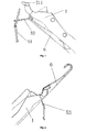
FIG.1 is an overall view of the present invention. -
FIG.2 is a structure view of the present invention. -
FIG.3 is a structure view of the needle jack of the present invention. -
FIG.4 ,FIG.5 ,FIG.6 andFIG.7 are flowcharts illustrating looping and clearing of the present invention. -
FIG.8 ,FIG.9 ,FIG.10 andFIG.11 are flowcharts illustrating turning between the needle bushes of the present invention. -
FIG.12 ,FIG.13 and FIG.14 are flowcharts illustrating turning between the needle bush and the major needle of the present invention. - Reference is made to the drawings. A knitting
needle 1 in this embodiment consists of twoidentical needle jacks 2, i.e. left needle jack and right needle jack; theneedle jacks 2 are flaky, a plurality ofgauges 3 are arranged between the two needle jacks, and the two needle jacks are integrally fixed by a plurality of connectingpins 4; theneedle jack 2 comprises ahead 21 and amain body 22, and thegauges 3 and the connectingpins 4 are located on themain body 22; thehead 21 of theneedle jack 2 is provided with a pointedfront end 211, the part behind thefront end 211 is recessed downwards to form afirst groove 212, thefirst groove 212 is extended backwards and protruded upwards to form aneedle ear 213 in the shape of an acute angle, and theneedle ear 213 is extended backwards and recessed downwards to form asecond groove 214; thesecond groove 214 is smaller than thefirst groove 212; and the thickness of theneedle ear 213 is smaller than those of the other parts of theneedle jack 2. - The working process of this embodiment is as follows: when clearing is needed, as shown in
FIG.4 ,FIG.5 ,FIG.6 andFIG.7 , aloop 51 is already formed on amajor needle 6, themajor needle 6 is pushed by a cam to move upwards to hook anew yarn 52 in order to prepare for another looping, meanwhile, the knittingneedle 1 in this embodiment is moved downwards and reset in a majorneedle clamping groove 61 before the formedloop 51; at this moment, the formedloop 51 is moved downwards in relation to themajor needle 6 to enter afirst groove 212 of the knittingneedle 1 in this embodiment, and the knittingneedle 1 in this embodiment receives theformed loop 51; themajor needle 6 that hooks thenew yarn 21 is moved downwards, and the knittingneedle 1 in this embodiment drives the formedloop 51 to move upwards; themajor needle 6 is continuously moved downwards and the knittingneedle 1 in this embodiment is continuously moved upwards to form thenew loop 52, and simultaneously, theold loop 51 slips off thefront end 211 of the knittingneedle 1 in this embodiment. - When turning between the knitting needles is needed, as shown in
FIG.8 ,FIG.9 ,FIG.10 andFIG.11 , themajor needle 6 that requires turning is moved upwards, and the knittingneedle 1 in this embodiment is moved downwards to acquire aloop 53 that requires turning; themajor needle 6 is moved downwards, the knittingneedle 1 in this embodiment is moved upwards to drive the turning-requiringloop 53 to reach the turning position, meanwhile, another knitting needle 1' for needle connection is moved upwards to pass through the turning-requiringloop 53 and enter aneedle ear 213 part of the needle jack of the opposite needle bed to wait for needle connection; the knitting needle 1' for needle connection hooks the turning-requiringloop 53 by asecond groove 213 thereof and keeps stationary, and the knittingneedle 1 for turning is moved downwards to leave away from theloop 53; and the knitting needle 1' for needle connection hooks the turning-requiringloop 53 and is reset near themajor needle 6 to complete turning between the front and rear needle beds. - When turning between the knitting needle and the major needle is needed, as shown in
FIG.12 ,FIG.13 and FIG.14 , theneedle 1 for turning acquires a turning-requiringloop 54 and is moved upwards to reach the turning position; the major needle 6' for needle connection is correspondingly moved upwards to pass through the turning-requiringloop 54 and enter theneedle ear 213 part of the needle jack of the opposite needle bed to wait for needle connection; the major needle 6' for needle connection hooks the turning-requiringloop 54 and keeps stationary, and the knittingneedle 1 for turning is moved downwards to leave away from theloop 54; and the major needle 6' for needle connection hooks the yarn and is then reset to finish the turning process.
Claims (1)
- A knitting needle for a flat knitting machine, characterized in that: the knitting needle consists of two identical needle jacks, i.e. left needle jack and right needle jack; the needle jacks are flaky, a plurality of gauges are arranged between the two needle jacks, and the two needle jacks are integrally fixed by a plurality of connecting pins; the needle jack comprises a head and a main body, and the gauges and the connecting pins are located on the main body; the head of the needle jack is provided with a pointed front end, the part behind the front end is recessed downwards to form a first groove, the first groove is extended backwards and protruded upwards to form a needle ear in the shape of an acute angle, and the needle ear is extended backwards and recessed downwards to form a second groove; the second groove is smaller than the first groove; and the thickness of the needle ear is smaller than those of the other parts of the needle jack.
Applications Claiming Priority (1)
| Application Number | Priority Date | Filing Date | Title |
|---|---|---|---|
| CN201310278223XA CN103334223A (en) | 2013-07-04 | 2013-07-04 | Knitting needle for flat knitting machine |
Publications (2)
| Publication Number | Publication Date |
|---|---|
| EP2767626A1 true EP2767626A1 (en) | 2014-08-20 |
| EP2767626B1 EP2767626B1 (en) | 2015-06-10 |
Family
ID=49242418
Family Applications (1)
| Application Number | Title | Priority Date | Filing Date |
|---|---|---|---|
| EP14151077.6A Active EP2767626B1 (en) | 2013-07-04 | 2014-01-14 | Knitting needle for flat knitting machine |
Country Status (2)
| Country | Link |
|---|---|
| EP (1) | EP2767626B1 (en) |
| CN (1) | CN103334223A (en) |
Cited By (3)
| Publication number | Priority date | Publication date | Assignee | Title |
|---|---|---|---|---|
| CN109750413A (en) * | 2019-02-28 | 2019-05-14 | 宁波慈星股份有限公司 | A kind of compound needle for straight-bar machines |
| JP2019105011A (en) * | 2017-12-14 | 2019-06-27 | 株式会社島精機製作所 | Composite needle |
| EP3889330A1 (en) | 2020-04-01 | 2021-10-06 | Groz-Beckert KG | Textile tool pair and method for equipping a textile machine |
Families Citing this family (2)
| Publication number | Priority date | Publication date | Assignee | Title |
|---|---|---|---|---|
| DE102014103261B4 (en) * | 2014-03-11 | 2017-02-23 | Hugo Kern Und Liebers Gmbh & Co. Kg Platinen- Und Federnfabrik | Process for producing a thread-contacting element and thread-contacting element, in particular for knitting or knitting machines |
| CN109352267B (en) * | 2018-10-11 | 2020-10-16 | 宁波慈星股份有限公司 | Method for processing transfer needle in flat knitting machine |
Citations (4)
| Publication number | Priority date | Publication date | Assignee | Title |
|---|---|---|---|---|
| GB2112819A (en) * | 1981-12-23 | 1983-07-27 | Schieber Universal Maschf | Slider needle |
| US5987932A (en) * | 1997-05-27 | 1999-11-23 | Atelier De Construction Steiger S.A. | Slider type needle for knitting machine |
| EP1203838A1 (en) * | 1999-05-19 | 2002-05-08 | Shima Seiki Mfg., Ltd | Compound needle |
| US20020112509A1 (en) * | 2001-02-20 | 2002-08-22 | Marcello Baseggio | Sliding-tongue compound needle for a knitting machine |
Family Cites Families (8)
| Publication number | Priority date | Publication date | Assignee | Title |
|---|---|---|---|---|
| JP2001032154A (en) * | 1999-07-15 | 2001-02-06 | Shima Seiki Mfg Ltd | Compound needle for knitting machine |
| WO2004057081A1 (en) * | 2002-12-20 | 2004-07-08 | Shima Seiki Manufacturing, Ltd. | Compound needle |
| JP4348286B2 (en) * | 2004-12-09 | 2009-10-21 | 株式会社島精機製作所 | Flat knitting machine |
| JP5604509B2 (en) * | 2010-03-26 | 2014-10-08 | 株式会社島精機製作所 | Compound needle and flat knitting machine |
| JP5732316B2 (en) * | 2010-06-18 | 2015-06-10 | 株式会社島精機製作所 | Compound needle of flat knitting machine |
| JP5525344B2 (en) * | 2010-06-18 | 2014-06-18 | 株式会社島精機製作所 | Compound needle of flat knitting machine |
| JP5719544B2 (en) * | 2010-08-06 | 2015-05-20 | 株式会社島精機製作所 | Compound needle of flat knitting machine |
| CN203333962U (en) * | 2013-07-04 | 2013-12-11 | 宁波慈星股份有限公司 | Knitting needle used for flat knitting machine |
-
2013
- 2013-07-04 CN CN201310278223XA patent/CN103334223A/en active Pending
-
2014
- 2014-01-14 EP EP14151077.6A patent/EP2767626B1/en active Active
Patent Citations (4)
| Publication number | Priority date | Publication date | Assignee | Title |
|---|---|---|---|---|
| GB2112819A (en) * | 1981-12-23 | 1983-07-27 | Schieber Universal Maschf | Slider needle |
| US5987932A (en) * | 1997-05-27 | 1999-11-23 | Atelier De Construction Steiger S.A. | Slider type needle for knitting machine |
| EP1203838A1 (en) * | 1999-05-19 | 2002-05-08 | Shima Seiki Mfg., Ltd | Compound needle |
| US20020112509A1 (en) * | 2001-02-20 | 2002-08-22 | Marcello Baseggio | Sliding-tongue compound needle for a knitting machine |
Cited By (5)
| Publication number | Priority date | Publication date | Assignee | Title |
|---|---|---|---|---|
| JP2019105011A (en) * | 2017-12-14 | 2019-06-27 | 株式会社島精機製作所 | Composite needle |
| CN109750413A (en) * | 2019-02-28 | 2019-05-14 | 宁波慈星股份有限公司 | A kind of compound needle for straight-bar machines |
| CN109750413B (en) * | 2019-02-28 | 2023-09-29 | 宁波慈星股份有限公司 | Composite needle for flat knitting machine |
| EP3889330A1 (en) | 2020-04-01 | 2021-10-06 | Groz-Beckert KG | Textile tool pair and method for equipping a textile machine |
| WO2021198201A1 (en) | 2020-04-01 | 2021-10-07 | Groz-Beckert Kommanditgesellschaft | Textile tool part pair and method for equipping a textile machine |
Also Published As
| Publication number | Publication date |
|---|---|
| CN103334223A (en) | 2013-10-02 |
| EP2767626B1 (en) | 2015-06-10 |
Similar Documents
| Publication | Publication Date | Title |
|---|---|---|
| EP2767626A1 (en) | Knitting needle for flat knitting machine | |
| CN203333962U (en) | Knitting needle used for flat knitting machine | |
| CN103361899B (en) | Multi-needle bar module for sewing machine | |
| CN103352336B (en) | Multi-needle-bar sewing machine | |
| CN202766758U (en) | Presser foot device | |
| CN208279800U (en) | Numerical control big round needle loom guide wire | |
| CN109295622B (en) | Automatic thread trimming mechanism of sewing machine and sewing machine | |
| CN102776703A (en) | Presser foot device | |
| CN208776950U (en) | A kind of dual-needle-bar mechanism | |
| CN204138871U (en) | A kind of loom drag link mechanism | |
| CN203360796U (en) | Multi-needle-rod module for sewing machine | |
| CN110387642A (en) | A kind of crosspointer longitudinal direction colour changing computer embroidery machine | |
| CN202072883U (en) | Sinker needle block for warp knitting machine | |
| CN203212796U (en) | Needle for warp knitting machine | |
| CN107022851B (en) | Thread hooking device of sleeving and sewing all-in-one machine | |
| CN211227570U (en) | Automatic yarn feeding device for knitting equipment | |
| CN106381604B (en) | Looping mechanism of artificial lawn warp knitting machine | |
| CN203212778U (en) | Warp knitting machine with multi-hole-type cam swing arms | |
| CN103668755B (en) | Yarn carrier moving device for circular knitting machine | |
| CN208649586U (en) | A kind of pair mouth shuttle line crossing bracket | |
| CN203403259U (en) | Sewing machine with multiple needle rods | |
| CN204982275U (en) | Looping mechanism of artifical lawn tricot machine | |
| CN204491155U (en) | A kind of adjustable guide bar of warp knitting machine retracting mechanism | |
| CN220149776U (en) | Mountain plate device capable of being knitted and hung in same row | |
| CN204097716U (en) | A kind of multi-needle bar Sewing machines |
Legal Events
| Date | Code | Title | Description |
|---|---|---|---|
| PUAI | Public reference made under article 153(3) epc to a published international application that has entered the european phase |
Free format text: ORIGINAL CODE: 0009012 |
|
| 17P | Request for examination filed |
Effective date: 20140704 |
|
| AK | Designated contracting states |
Kind code of ref document: A1 Designated state(s): AL AT BE BG CH CY CZ DE DK EE ES FI FR GB GR HR HU IE IS IT LI LT LU LV MC MK MT NL NO PL PT RO RS SE SI SK SM TR |
|
| AX | Request for extension of the european patent |
Extension state: BA ME |
|
| 17Q | First examination report despatched |
Effective date: 20141211 |
|
| GRAP | Despatch of communication of intention to grant a patent |
Free format text: ORIGINAL CODE: EPIDOSNIGR1 |
|
| INTG | Intention to grant announced |
Effective date: 20150330 |
|
| GRAS | Grant fee paid |
Free format text: ORIGINAL CODE: EPIDOSNIGR3 |
|
| GRAA | (expected) grant |
Free format text: ORIGINAL CODE: 0009210 |
|
| AK | Designated contracting states |
Kind code of ref document: B1 Designated state(s): AL AT BE BG CH CY CZ DE DK EE ES FI FR GB GR HR HU IE IS IT LI LT LU LV MC MK MT NL NO PL PT RO RS SE SI SK SM TR |
|
| REG | Reference to a national code |
Ref country code: GB Ref legal event code: FG4D |
|
| REG | Reference to a national code |
Ref country code: CH Ref legal event code: EP |
|
| REG | Reference to a national code |
Ref country code: AT Ref legal event code: REF Ref document number: 730956 Country of ref document: AT Kind code of ref document: T Effective date: 20150715 |
|
| REG | Reference to a national code |
Ref country code: DE Ref legal event code: R096 Ref document number: 602014000037 Country of ref document: DE |
|
| REG | Reference to a national code |
Ref country code: IE Ref legal event code: FG4D |
|
| PG25 | Lapsed in a contracting state [announced via postgrant information from national office to epo] |
Ref country code: FI Free format text: LAPSE BECAUSE OF FAILURE TO SUBMIT A TRANSLATION OF THE DESCRIPTION OR TO PAY THE FEE WITHIN THE PRESCRIBED TIME-LIMIT Effective date: 20150610 Ref country code: NO Free format text: LAPSE BECAUSE OF FAILURE TO SUBMIT A TRANSLATION OF THE DESCRIPTION OR TO PAY THE FEE WITHIN THE PRESCRIBED TIME-LIMIT Effective date: 20150910 Ref country code: LT Free format text: LAPSE BECAUSE OF FAILURE TO SUBMIT A TRANSLATION OF THE DESCRIPTION OR TO PAY THE FEE WITHIN THE PRESCRIBED TIME-LIMIT Effective date: 20150610 Ref country code: ES Free format text: LAPSE BECAUSE OF FAILURE TO SUBMIT A TRANSLATION OF THE DESCRIPTION OR TO PAY THE FEE WITHIN THE PRESCRIBED TIME-LIMIT Effective date: 20150610 |
|
| REG | Reference to a national code |
Ref country code: AT Ref legal event code: MK05 Ref document number: 730956 Country of ref document: AT Kind code of ref document: T Effective date: 20150610 |
|
| REG | Reference to a national code |
Ref country code: NL Ref legal event code: MP Effective date: 20150610 |
|
| PG25 | Lapsed in a contracting state [announced via postgrant information from national office to epo] |
Ref country code: BG Free format text: LAPSE BECAUSE OF FAILURE TO SUBMIT A TRANSLATION OF THE DESCRIPTION OR TO PAY THE FEE WITHIN THE PRESCRIBED TIME-LIMIT Effective date: 20150910 Ref country code: GR Free format text: LAPSE BECAUSE OF FAILURE TO SUBMIT A TRANSLATION OF THE DESCRIPTION OR TO PAY THE FEE WITHIN THE PRESCRIBED TIME-LIMIT Effective date: 20150911 Ref country code: LV Free format text: LAPSE BECAUSE OF FAILURE TO SUBMIT A TRANSLATION OF THE DESCRIPTION OR TO PAY THE FEE WITHIN THE PRESCRIBED TIME-LIMIT Effective date: 20150610 Ref country code: RS Free format text: LAPSE BECAUSE OF FAILURE TO SUBMIT A TRANSLATION OF THE DESCRIPTION OR TO PAY THE FEE WITHIN THE PRESCRIBED TIME-LIMIT Effective date: 20150610 |
|
| PG25 | Lapsed in a contracting state [announced via postgrant information from national office to epo] |
Ref country code: EE Free format text: LAPSE BECAUSE OF FAILURE TO SUBMIT A TRANSLATION OF THE DESCRIPTION OR TO PAY THE FEE WITHIN THE PRESCRIBED TIME-LIMIT Effective date: 20150610 |
|
| PG25 | Lapsed in a contracting state [announced via postgrant information from national office to epo] |
Ref country code: IS Free format text: LAPSE BECAUSE OF FAILURE TO SUBMIT A TRANSLATION OF THE DESCRIPTION OR TO PAY THE FEE WITHIN THE PRESCRIBED TIME-LIMIT Effective date: 20151010 Ref country code: PL Free format text: LAPSE BECAUSE OF FAILURE TO SUBMIT A TRANSLATION OF THE DESCRIPTION OR TO PAY THE FEE WITHIN THE PRESCRIBED TIME-LIMIT Effective date: 20150610 Ref country code: CZ Free format text: LAPSE BECAUSE OF FAILURE TO SUBMIT A TRANSLATION OF THE DESCRIPTION OR TO PAY THE FEE WITHIN THE PRESCRIBED TIME-LIMIT Effective date: 20150610 Ref country code: RO Free format text: LAPSE BECAUSE OF NON-PAYMENT OF DUE FEES Effective date: 20150610 Ref country code: SK Free format text: LAPSE BECAUSE OF FAILURE TO SUBMIT A TRANSLATION OF THE DESCRIPTION OR TO PAY THE FEE WITHIN THE PRESCRIBED TIME-LIMIT Effective date: 20150610 Ref country code: PT Free format text: LAPSE BECAUSE OF FAILURE TO SUBMIT A TRANSLATION OF THE DESCRIPTION OR TO PAY THE FEE WITHIN THE PRESCRIBED TIME-LIMIT Effective date: 20151012 Ref country code: AT Free format text: LAPSE BECAUSE OF FAILURE TO SUBMIT A TRANSLATION OF THE DESCRIPTION OR TO PAY THE FEE WITHIN THE PRESCRIBED TIME-LIMIT Effective date: 20150610 |
|
| REG | Reference to a national code |
Ref country code: DE Ref legal event code: R097 Ref document number: 602014000037 Country of ref document: DE |
|
| PLBE | No opposition filed within time limit |
Free format text: ORIGINAL CODE: 0009261 |
|
| STAA | Information on the status of an ep patent application or granted ep patent |
Free format text: STATUS: NO OPPOSITION FILED WITHIN TIME LIMIT |
|
| PG25 | Lapsed in a contracting state [announced via postgrant information from national office to epo] |
Ref country code: DK Free format text: LAPSE BECAUSE OF FAILURE TO SUBMIT A TRANSLATION OF THE DESCRIPTION OR TO PAY THE FEE WITHIN THE PRESCRIBED TIME-LIMIT Effective date: 20150610 |
|
| 26N | No opposition filed |
Effective date: 20160311 |
|
| PG25 | Lapsed in a contracting state [announced via postgrant information from national office to epo] |
Ref country code: BE Free format text: LAPSE BECAUSE OF NON-PAYMENT OF DUE FEES Effective date: 20160131 Ref country code: SI Free format text: LAPSE BECAUSE OF FAILURE TO SUBMIT A TRANSLATION OF THE DESCRIPTION OR TO PAY THE FEE WITHIN THE PRESCRIBED TIME-LIMIT Effective date: 20150610 |
|
| PG25 | Lapsed in a contracting state [announced via postgrant information from national office to epo] |
Ref country code: LU Free format text: LAPSE BECAUSE OF FAILURE TO SUBMIT A TRANSLATION OF THE DESCRIPTION OR TO PAY THE FEE WITHIN THE PRESCRIBED TIME-LIMIT Effective date: 20160114 |
|
| PG25 | Lapsed in a contracting state [announced via postgrant information from national office to epo] |
Ref country code: MC Free format text: LAPSE BECAUSE OF FAILURE TO SUBMIT A TRANSLATION OF THE DESCRIPTION OR TO PAY THE FEE WITHIN THE PRESCRIBED TIME-LIMIT Effective date: 20150610 |
|
| REG | Reference to a national code |
Ref country code: FR Ref legal event code: ST Effective date: 20160930 |
|
| REG | Reference to a national code |
Ref country code: IE Ref legal event code: MM4A |
|
| PG25 | Lapsed in a contracting state [announced via postgrant information from national office to epo] |
Ref country code: FR Free format text: LAPSE BECAUSE OF NON-PAYMENT OF DUE FEES Effective date: 20160201 |
|
| PG25 | Lapsed in a contracting state [announced via postgrant information from national office to epo] |
Ref country code: BE Free format text: LAPSE BECAUSE OF FAILURE TO SUBMIT A TRANSLATION OF THE DESCRIPTION OR TO PAY THE FEE WITHIN THE PRESCRIBED TIME-LIMIT Effective date: 20150610 |
|
| PG25 | Lapsed in a contracting state [announced via postgrant information from national office to epo] |
Ref country code: IE Free format text: LAPSE BECAUSE OF NON-PAYMENT OF DUE FEES Effective date: 20160114 |
|
| PG25 | Lapsed in a contracting state [announced via postgrant information from national office to epo] |
Ref country code: NL Free format text: LAPSE BECAUSE OF FAILURE TO SUBMIT A TRANSLATION OF THE DESCRIPTION OR TO PAY THE FEE WITHIN THE PRESCRIBED TIME-LIMIT Effective date: 20150610 Ref country code: SE Free format text: LAPSE BECAUSE OF FAILURE TO SUBMIT A TRANSLATION OF THE DESCRIPTION OR TO PAY THE FEE WITHIN THE PRESCRIBED TIME-LIMIT Effective date: 20150610 |
|
| PG25 | Lapsed in a contracting state [announced via postgrant information from national office to epo] |
Ref country code: MT Free format text: LAPSE BECAUSE OF FAILURE TO SUBMIT A TRANSLATION OF THE DESCRIPTION OR TO PAY THE FEE WITHIN THE PRESCRIBED TIME-LIMIT Effective date: 20150610 |
|
| PG25 | Lapsed in a contracting state [announced via postgrant information from national office to epo] |
Ref country code: SM Free format text: LAPSE BECAUSE OF FAILURE TO SUBMIT A TRANSLATION OF THE DESCRIPTION OR TO PAY THE FEE WITHIN THE PRESCRIBED TIME-LIMIT Effective date: 20150610 Ref country code: HU Free format text: LAPSE BECAUSE OF FAILURE TO SUBMIT A TRANSLATION OF THE DESCRIPTION OR TO PAY THE FEE WITHIN THE PRESCRIBED TIME-LIMIT; INVALID AB INITIO Effective date: 20140114 Ref country code: CY Free format text: LAPSE BECAUSE OF FAILURE TO SUBMIT A TRANSLATION OF THE DESCRIPTION OR TO PAY THE FEE WITHIN THE PRESCRIBED TIME-LIMIT Effective date: 20150610 |
|
| PG25 | Lapsed in a contracting state [announced via postgrant information from national office to epo] |
Ref country code: MT Free format text: LAPSE BECAUSE OF FAILURE TO SUBMIT A TRANSLATION OF THE DESCRIPTION OR TO PAY THE FEE WITHIN THE PRESCRIBED TIME-LIMIT Effective date: 20160131 Ref country code: HR Free format text: LAPSE BECAUSE OF FAILURE TO SUBMIT A TRANSLATION OF THE DESCRIPTION OR TO PAY THE FEE WITHIN THE PRESCRIBED TIME-LIMIT Effective date: 20150610 Ref country code: MK Free format text: LAPSE BECAUSE OF FAILURE TO SUBMIT A TRANSLATION OF THE DESCRIPTION OR TO PAY THE FEE WITHIN THE PRESCRIBED TIME-LIMIT Effective date: 20150610 |
|
| GBPC | Gb: european patent ceased through non-payment of renewal fee |
Effective date: 20180114 |
|
| PG25 | Lapsed in a contracting state [announced via postgrant information from national office to epo] |
Ref country code: AL Free format text: LAPSE BECAUSE OF FAILURE TO SUBMIT A TRANSLATION OF THE DESCRIPTION OR TO PAY THE FEE WITHIN THE PRESCRIBED TIME-LIMIT Effective date: 20150610 |
|
| PG25 | Lapsed in a contracting state [announced via postgrant information from national office to epo] |
Ref country code: GB Free format text: LAPSE BECAUSE OF NON-PAYMENT OF DUE FEES Effective date: 20180114 |
|
| PGFP | Annual fee paid to national office [announced via postgrant information from national office to epo] |
Ref country code: IT Payment date: 20210129 Year of fee payment: 8 Ref country code: CH Payment date: 20210122 Year of fee payment: 8 |
|
| PGFP | Annual fee paid to national office [announced via postgrant information from national office to epo] |
Ref country code: DE Payment date: 20201217 Year of fee payment: 8 Ref country code: TR Payment date: 20210105 Year of fee payment: 8 |
|
| REG | Reference to a national code |
Ref country code: DE Ref legal event code: R119 Ref document number: 602014000037 Country of ref document: DE |
|
| REG | Reference to a national code |
Ref country code: CH Ref legal event code: PL |
|
| PG25 | Lapsed in a contracting state [announced via postgrant information from national office to epo] |
Ref country code: DE Free format text: LAPSE BECAUSE OF NON-PAYMENT OF DUE FEES Effective date: 20220802 |
|
| PG25 | Lapsed in a contracting state [announced via postgrant information from national office to epo] |
Ref country code: LI Free format text: LAPSE BECAUSE OF NON-PAYMENT OF DUE FEES Effective date: 20220131 Ref country code: CH Free format text: LAPSE BECAUSE OF NON-PAYMENT OF DUE FEES Effective date: 20220131 |
|
| PG25 | Lapsed in a contracting state [announced via postgrant information from national office to epo] |
Ref country code: IT Free format text: LAPSE BECAUSE OF NON-PAYMENT OF DUE FEES Effective date: 20220114 |