EP2767416A1 - Pneumatic tyre and manufacturing method therefor - Google Patents
Pneumatic tyre and manufacturing method therefor Download PDFInfo
- Publication number
- EP2767416A1 EP2767416A1 EP20120857840 EP12857840A EP2767416A1 EP 2767416 A1 EP2767416 A1 EP 2767416A1 EP 20120857840 EP20120857840 EP 20120857840 EP 12857840 A EP12857840 A EP 12857840A EP 2767416 A1 EP2767416 A1 EP 2767416A1
- Authority
- EP
- European Patent Office
- Prior art keywords
- wire
- bead
- tire
- wound body
- winding
- Prior art date
- Legal status (The legal status is an assumption and is not a legal conclusion. Google has not performed a legal analysis and makes no representation as to the accuracy of the status listed.)
- Granted
Links
Images


Classifications
-
- B—PERFORMING OPERATIONS; TRANSPORTING
- B29—WORKING OF PLASTICS; WORKING OF SUBSTANCES IN A PLASTIC STATE IN GENERAL
- B29D—PRODUCING PARTICULAR ARTICLES FROM PLASTICS OR FROM SUBSTANCES IN A PLASTIC STATE
- B29D30/00—Producing pneumatic or solid tyres or parts thereof
- B29D30/06—Pneumatic tyres or parts thereof (e.g. produced by casting, moulding, compression moulding, injection moulding, centrifugal casting)
- B29D30/48—Bead-rings or bead-cores; Treatment thereof prior to building the tyre
-
- B—PERFORMING OPERATIONS; TRANSPORTING
- B29—WORKING OF PLASTICS; WORKING OF SUBSTANCES IN A PLASTIC STATE IN GENERAL
- B29D—PRODUCING PARTICULAR ARTICLES FROM PLASTICS OR FROM SUBSTANCES IN A PLASTIC STATE
- B29D30/00—Producing pneumatic or solid tyres or parts thereof
- B29D30/06—Pneumatic tyres or parts thereof (e.g. produced by casting, moulding, compression moulding, injection moulding, centrifugal casting)
- B29D30/08—Building tyres
- B29D30/10—Building tyres on round cores, i.e. the shape of the core is approximately identical with the shape of the completed tyre
- B29D30/16—Applying the layers; Guiding or stretching the layers during application
- B29D30/1621—Applying the layers; Guiding or stretching the layers during application by feeding a continuous band and winding it spirally, i.e. the band is fed without relative movement along the core axis, to form an annular element
-
- B—PERFORMING OPERATIONS; TRANSPORTING
- B29—WORKING OF PLASTICS; WORKING OF SUBSTANCES IN A PLASTIC STATE IN GENERAL
- B29D—PRODUCING PARTICULAR ARTICLES FROM PLASTICS OR FROM SUBSTANCES IN A PLASTIC STATE
- B29D30/00—Producing pneumatic or solid tyres or parts thereof
- B29D30/06—Pneumatic tyres or parts thereof (e.g. produced by casting, moulding, compression moulding, injection moulding, centrifugal casting)
- B29D30/08—Building tyres
- B29D30/34—Building tyres by jointly covering two bead-rings, located parallel to each other at a distance apart, with fabric or cord layers
-
- B—PERFORMING OPERATIONS; TRANSPORTING
- B60—VEHICLES IN GENERAL
- B60C—VEHICLE TYRES; TYRE INFLATION; TYRE CHANGING; CONNECTING VALVES TO INFLATABLE ELASTIC BODIES IN GENERAL; DEVICES OR ARRANGEMENTS RELATED TO TYRES
- B60C15/00—Tyre beads, e.g. ply turn-up or overlap
- B60C15/0009—Tyre beads, e.g. ply turn-up or overlap features of the carcass terminal portion
- B60C15/0018—Tyre beads, e.g. ply turn-up or overlap features of the carcass terminal portion not folded around the bead core, e.g. floating or down ply
-
- B—PERFORMING OPERATIONS; TRANSPORTING
- B60—VEHICLES IN GENERAL
- B60C—VEHICLE TYRES; TYRE INFLATION; TYRE CHANGING; CONNECTING VALVES TO INFLATABLE ELASTIC BODIES IN GENERAL; DEVICES OR ARRANGEMENTS RELATED TO TYRES
- B60C15/00—Tyre beads, e.g. ply turn-up or overlap
- B60C15/04—Bead cores
-
- B—PERFORMING OPERATIONS; TRANSPORTING
- B29—WORKING OF PLASTICS; WORKING OF SUBSTANCES IN A PLASTIC STATE IN GENERAL
- B29D—PRODUCING PARTICULAR ARTICLES FROM PLASTICS OR FROM SUBSTANCES IN A PLASTIC STATE
- B29D30/00—Producing pneumatic or solid tyres or parts thereof
- B29D30/06—Pneumatic tyres or parts thereof (e.g. produced by casting, moulding, compression moulding, injection moulding, centrifugal casting)
- B29D30/48—Bead-rings or bead-cores; Treatment thereof prior to building the tyre
- B29D2030/485—Bead-rings or bead-cores; Treatment thereof prior to building the tyre the bead cores being made using a band containing a plurality of wires embedded in rubber
-
- B—PERFORMING OPERATIONS; TRANSPORTING
- B29—WORKING OF PLASTICS; WORKING OF SUBSTANCES IN A PLASTIC STATE IN GENERAL
- B29K—INDEXING SCHEME ASSOCIATED WITH SUBCLASSES B29B, B29C OR B29D, RELATING TO MOULDING MATERIALS OR TO MATERIALS FOR MOULDS, REINFORCEMENTS, FILLERS OR PREFORMED PARTS, e.g. INSERTS
- B29K2305/00—Use of metals, their alloys or their compounds, as reinforcement
-
- B—PERFORMING OPERATIONS; TRANSPORTING
- B60—VEHICLES IN GENERAL
- B60C—VEHICLE TYRES; TYRE INFLATION; TYRE CHANGING; CONNECTING VALVES TO INFLATABLE ELASTIC BODIES IN GENERAL; DEVICES OR ARRANGEMENTS RELATED TO TYRES
- B60C15/00—Tyre beads, e.g. ply turn-up or overlap
- B60C15/04—Bead cores
- B60C2015/046—Cable cores, i.e. cores made-up of twisted wires
-
- B—PERFORMING OPERATIONS; TRANSPORTING
- B60—VEHICLES IN GENERAL
- B60C—VEHICLE TYRES; TYRE INFLATION; TYRE CHANGING; CONNECTING VALVES TO INFLATABLE ELASTIC BODIES IN GENERAL; DEVICES OR ARRANGEMENTS RELATED TO TYRES
- B60C15/00—Tyre beads, e.g. ply turn-up or overlap
- B60C15/04—Bead cores
- B60C2015/048—Polygonal cores characterised by the winding sequence
Definitions
- the present invention relates to a pneumatic tire that exhibits better uniformity by improving a wire wound body for constituting its bead core, and a method for manufacturing the same.
- the core molding method includes a process in which various kinds of tire components such as an inner liner 9, an inner apex rubber 8i, an outer apex rubber 8o, a carcass ply 6A, a bead core 5, a belt 7, a tread rubber 2G, and a sidewall rubber 3G are attached and assembled on the inner core N to mold a green tire 1a.
- the method further comprises a process in which the green tire 1a with the inner core N is vulcanized in a tire mold. Since the core molding method may minimize a stretch of the green tire during the vulcanizing process, a tire with better uniformity is produced.
- the carcass ply 6A is assembled in the green tire without being turned up its both ends around the bead core.
- a wire wound body 10 that is arranged axially one side or both sides (both sides in this embodiment) of the carcass ply 6A in each bead portion is employed.
- the wire wound body 10 is formed by spirally wound a bead wire 10a, for example.
- the bead wire 10a of the conventional wire wound body 10 is wound so that a radius R of curvature of the bead wire 10a from its winding center 10c is gradually increased.
- Such a configuration of the wire wound body 10 may lead to deterioration of weight uniformity of the tire because the wire wound body 10 has its gravity center 10g in different place with respect to its winding center 10c.
- Patent Document 1 Japanese Unexamined Patent Application Publication No. 2006-160236
- the present invention has been worked out in the light of the circumstances described above, and has a main object of providing a pneumatic tire that exhibits better uniformity by improving the wire wound body for constituting the bead core, and a method for manufacturing the same.
- a pneumatic tire comprising a tread portion, a pair of sidewall portions, a pair of bead portions each with a bead core therein, a carcass extending between the bead cores, at least one of the bead cores comprising a wire wound body in which one bead wire is spirally wound in a continuous around a tire rotational axis so that a plurality of layers of the bead wire are formed in a radial direction of the tire, and the wire wound body comprising a first part and a second part, the first part comprising a plurality of layers of the bead wire each extending in a circumferential direction of the tire having a constant radius from the tire rotational axis, the second part comprising a plurality of layers of the bead wire each extending in the circumferential direction of the tire while changing its radius from the tire rotational axis.
- the pneumatic tire in accordance with the present invention includes a wire wound body in which one bead wire is spirally wound in a continuous around a tire rotational axis so that a plurality of layers of the bead wire are formed in a radial direction of the tire.
- the wire wound body includes a first part and a second part.
- the first part includes a plurality of layers of the bead wire each extending in a circumferential direction of the tire having a constant radius from the tire rotational axis.
- the second part includes a plurality of layers of the bead wire each extending in the circumferential direction of the tire while changing its radius from the tire rotational axis. Since the wire wound body having the first part may have its gravity center so as to be close to the tire rotational axis that corresponds to the winding center of the bead wire, better weight uniformity around the tire rotational axis may be offered.
- a pneumatic tire (hereinafter, it may be simply referred to the "tire") 1 in accordance with the present invention includes a tread portion 2, a pair of sidewall portions 3, a pair of bead portions 4 each with a bead core 5 therein, and a carcass 6 extending between bead cores 5 and 5.
- the tire 1 in accordance with the present embodiment is embodied as a passenger car tire.
- the tire 1 further includes a belt layer 7 disposed radially outward of the carcass 6 in the tread portion 2, and an inner liner 9 disposed inside the carcass 6.
- the inner liner 9 that is made of an air impermeable rubber forms an inner cavity surface (i) of the tire.
- FIG. 1 illustrates the tire 1 under a standard condition in which the tire 1 is mounted on a standard wheel rim (not shown) and inflated to a standard pressure but no tire load is loaded.
- the standard wheel rim is a wheel rim officially approved for the tire by standards organizations, and the standard wheel rim is the "standard rim” specified in JATMA, the “Measuring Rim” in ETRTO, the “Design Rim” in TRA or the like, for example.
- the standard pressure is a pressure officially approved for the tire by standards organizations, and the standard pressure is the "maximum air pressure” in JATMA, the “Inflation Pressure” in ETRTO, and the maximum pressure given in the "Tire Load Limits at Various Cold Inflation Pressures" table in TRA or the like.
- the standard pressure is uniformly defined as 180 kPa.
- the carcass 6 includes a carcass ply 6A of cords which extends between bead cores 5 and 5 through the tread portion 2 and sidewall portions 3. Each of both ends of the carcass ply 6A terminates at the bead core 5 without being turned up around the bead core 5.
- the carcass cords are arranged at an angle in a range of from 75 to 90 degrees with respect to a tire equator C.
- an organic fiber cord is employed, for example.
- the belt layer 7 includes at least two belt plies of belt cords laid at an angle in a range of from 15 to 40 degrees with respect to the tire equator C.
- the belt layer 7 includes two belt plies 7A and 7B overlapped each other so that each belt cords of plies are crossed.
- a steel cord is employed for example.
- the bead portion 4 is disposed a chafer rubber 4 with high hardness for preventing wear due to contact with the wheel rim (not shown).
- the chafer rubber 4g in this present embodiment includes an inner portion 4ga extending along the inner cavity surface (i) of the tire, and an outer portion 4gb extending along the bottom of the bead portion 4 and outer surface of the bead portion 4 so as to have a U-shaped cross section.
- the bead portion 4 is further disposed an inner apex rubber 8i arranged axially inward of the carcass 6, and an outer apex rubber 8o arranged axially outward of the carcass 6.
- Each of the apex rubber 8i and 8o tapers off to its radially outer end.
- the bead core 5 includes a wire wound body 10 in which one bead wire 10a is spirally wound along the carcass ply 6A.
- the bead core 5 is employed an inner wire wound body 11 arranged axially inward of the carcass ply 6A, and an outer wire wound body 12 arranged axially outward of the carcass ply 6A.
- each of the wire wound bodies 11 and 12 is configured to a single stack of bead wires in the radial direction of the tire.
- each of the wire wound body 11 and 12 may be configured to a plurality of stacks of bead wires, which are laterally and adjacently arranged.
- the end portion 6e of the carcass ply 6A is sandwiched in between the inner wire wound body 11 and the outer wire wound body 12 to be firmly fixed therebetween.
- the number of winding of the bead wire in each wire wound body 11 and 12 are the same. In another aspect of the invention, the number of winding of the bead wire in each wire wound body 11 and 12 may be different.
- the wire wound body 10 is formed by spirally wound one bead wire 10a around a winding center 10c corresponding to the tire rotational axis CL so that a plurality of layers of the bead wire 10a are formed in the radial direction of the tire.
- the wire wound body 10 includes a first part 13 and a second part 14.
- the first part 13 includes a plurality of layers of the bead wire 10a each extending in a circumferential direction of the tire having a constant radius R from the tire rotational axis CL.
- the second part 14 includes a plurality of layers of the bead wire 10a each extending in the circumferential direction of the tire while changing its radius from the tire rotational axis CL.
- the wire wound body 10 including the first part 13 may have its gravity center 10g so as to be close to the tire rotational axis CL that corresponds to the winding center 10c, better weight uniformity around the tire rotational axis may be offered.
- the first part 13 occupies most of the wire wound body 10.
- the second part 14 has the central angle ⁇ 1 in a range of from 4 to 20 degrees of the wire wound body 10.
- the central angle ⁇ 1 of the second part 14 is excessively small, uniformity of the tire may be deteriorated due to a difficulty in maintaining the shape of the second part 14.
- the central angle ⁇ 1 of the second part 14 is excessively large, the difference between the winding center 10c of the wire wound body 10 and its gravity center 10g might become larger.
- the central angle ⁇ 1 of the second part 14 is set in a range of not less than 4 degrees, more preferably not less than 8 degrees, but preferably not more than 20 degrees, more preferably not more than 16 degrees.
- the second part 14 includes a plurality of layers of the bead wire each radius gradually increasing from a side of a winding-starting end 10s toward a side of a winding-terminal end 10e of the bead wire 10a.
- the amount of increase of the radius R of the second part 14 from a side of a winding-starting end 10s toward a side of a winding-terminal end 10e corresponds to a diameter d of the bead wire 10a.
- the second part 14 is configured as a straight part 14a that extends in a straight manner between the end 13e of the first part 13 and the end 14e of the second part 14.
- the second part 14 may be configured as an arc part 14b (shown in FIG. 2(b) ) that extends in an arc manner.
- radially adjacent layers of the bead wire 10a are arranged so as to come into contact one another. This configuration may be helpful to further reduce the difference between the gravity center 10c of the wire wound body 10 and the winding center 10c.
- the wire wound body 10 has a winding-starting end 10a and a winding-terminal end 10e, and the winding-terminal end 10e is provided with the same position of the winding-starting end 10a in the circumferential direction. Namely, the winding-terminal end 10e is positioned on a radial line that passes both the tire rotational axis CL and the winding-starting end 10s. This configuration may be helpful to further reduce the difference between the gravity center 10c of the wire wound body 10 and the winding center 10c.
- the tire 1 in accordance with the present embodiment is manufactured from a green tire 1a like the one shown in FIG. 6(a) through a vulcanization process.
- the method and apparatus M for manufacturing the tire (green tire 1a) will be described.
- the apparatus M includes an inner core N having an outer surface N1 for molding the inner cavity (i) (shown in FIG. 1 ) of the tire, a driving device Q for rotating the inner core N, and a pasting device P for supplying the bead wire and pasting it directly or indirectly on the outer surface N1 of the inner core N.
- the inner core N includes the outer surface N1, and a pair of flanges F each provided on its bead region of the inner core so as to protrude axially outwardly.
- the outer surface N1 has a three-dimensional shape that corresponds to an inner cavity of the tire under a 5% inflated condition in which the tire is mounted on the standard rim and inflated to a 5% inner pressure of the standard pressure.
- the tire 1 is firstly inflated up to the standard pressure and then the inner pressure is reduced down to the 5% of the standard pressure.
- the inner core N may be made of a metallic material or a heat-resistance resin to resist high temperature and pressure during the vulcanization process.
- the outer surface N1 of the inner core N includes a pair of a bead molding surfaces Na for molding the bead portion 4 of the tire.
- the driving device Q includes an arm 15 having a L-shape, and a base 16 that rotatably supports the arm 15.
- the base 16 is configured to a rectangular shape, for example.
- the arm 15 is provided with a horizontally extending first supporting axis 17 at its upper end side, and a vertically extending second supporting axis 18 at its lower end side.
- the second supporting axis is along with the Z-axis.
- the first supporting axis 17 supports the inner core N so that the inner core N can rotate around the tire rotational axis CL.
- the second supporting axis 18 supports the arm 15 so that the arm 15 can turn around the turning center axis Ca that corresponds to a center of the second supporting axis 18.
- the rotational angle of the first supporting axis 17 and the turning angle of the second supporting axis 18 are controlled by a computer device based on previously programmed procedures.
- the turning center axis Ca passes through a center O of the inner core N at which the tire rotational axis CL and the equatorial plane of the inner core N intersect.
- the base 16 is movably provided along the Y-axis.
- the base 16 is provided on its bottom side with a slider 23a guided on a rail 23b extending along the Y-axis.
- the pasting device P includes a delivering roller 19, a pushing roller device 20, and a cutting tool 21.
- the delivering roller 19 guides the bead wire 10a sent out from the upstream side toward the inner core N through the pushing roller device 20.
- the pushing roller device 20 pushes the bead wire 10a sent out from the delivering roller 19 to paste it directly or indirectly on the outer surface N1 of the inner core N.
- the cutting tool 21 can cut the bead wire 10a.
- the bead wire 10a is previously coated with unvulcanized rubber so that the bead wire 10a is easily stuck on the inner core N.
- the delivering roller 19 may further include a plurality of guide rollers 19a for removing a temporary unexpected crease such as curl or wave of the bead wire 10a.
- the guide rollers 19a are rotatably supported on a bracket 22 and aligned so as to guide the bead wire 10a in a straight manner along the Y-axis.
- the pushing roller device 20 includes a roller 20a that guides the bead wire 10a, and an actuator 20b such as a cylinder actuator that pushes the roller 20a toward the inner core N so as to paste the bead wire 10a thereon.
- the equatorial plane of the roller 20a is arranged in the same plane of the equatorial plane 19C of the delivering roller 19 as shown in FIG. 4 .
- the cutting tool 21 includes a cutter 21a that can cut the bead wire 10a by pressing on it, and an actuator device 21b such as a cylinder actuator that can drive the cutter 21a downwardly to cut the bead wire 10a.
- an actuator device 21b such as a cylinder actuator that can drive the cutter 21a downwardly to cut the bead wire 10a.
- the inner core N is firstly rotatably attached on the first supporting axis 17 of the driving device Q.
- the pasting device P is positioned away from the inner core N.
- the inner portion 4ga of the chafer rubber 4g and the inner liner 9 which have sticky property are pasted on the outer surface N1 of the inner core N.
- the inner apex rubber 8i is attached on the outer surfaces of the chafer rubber 4g and the inner liner 9 (Shown in FIG. 5 ).
- the outer surface of the inner apex rubber 8i includes the predetermined area S1 where the bead wire 10a should be wound.
- the bead molding surfaces Na of the inner core N is set its position to face the pushing roller device 20 of the pasting device P at a predetermined space so that the equatorial plane 19C of the delivering roller 19 is parallel to the tire rotational axis CL of the inner core N in the top view as shown in FIG. 4 . Furthermore, the rotational axis Cr of the roller 20a is set in a height same as the tire rotational axis CL of the inner core N.
- a wire wound body forming step is performed to form the inner wire wound body 11.
- the bead wire 10a is continuously wound on the predetermined area S1 around the winding center 10c corresponding to the tire rotational axis CL.
- the wire wound body forming step includes a wire fixing step (shown in FIG. 5 ) in which a winding-starting end 10s of the bead wire 10a is pushed and fixed on the predetermined area S1, and then a wire winding step (shown in FIG. 4 ) in which the bead wire 10a is spirally and continuously wound on the predetermined area S1 by rotating the inner core N around the tire rotational axis CL.
- the actuator 20b of the pushing roller device 20 forces the roller 20a so as to fix the starting-end 10s of the bead wire on the predetermined area S1 of the inner core N.
- the starting-end 10s is pasted on the predetermined area S1.
- the starting-end 10s of the bead wire 10a is fixed at the radially innermost place 8t of the inner apex rubber 8i. Since the inner apex rubber 8i is an unvulcanized state having sticky property during the wire fixing step, the bead wire 10a may easily be pasted thereon.
- the wire winding step alternately includes a first rotating step in which the inner core N is rotated to wind the bead wire 10a while maintaining an angle ⁇ 1 in constant between the tire rotational axis CL and the Y-axis direction that is a feeding direction of the bead wire 10a to the internal core N, and a second rotating step in which the inner core N is rotated to wind the bead wire 10a while gradually increasing the angle ⁇ 1.
- the bead wire 10a is wound at a constant radius R from the tire rotational axis CL. Hence, the first part 13 is formed on the predetermined area S1.
- the angle ⁇ 1 may be increased by turning the inner core N around the turning center axis Ca in a clockwise direction.
- the winding radius R of the bead wire 10a increases while increasing the angle ⁇ 1.
- the inner core N is rotated around the tire rotational axis CL while gradually increasing the angle ⁇ 1 by turning the inner core N around the turning center axis Ca.
- the bead wire 10a is wound on the predetermined area S1 while increasing its winding radius R.
- the second part 14 is formed.
- the inner core N which is under the initial condition of the wire winding step is illustrated by the two-dot chain line.
- the second winding step when the inner core N is simply turned around the turning center axis Ca, the predetermined area S1 relatively moves toward the roller 20a, thereby decreasing the distance thereto.
- the inner core is moved backward along the Y-axis while being turned around the turning-center axis Ca to increase the angle ⁇ 1.
- the distance L between the roller 20a and the predetermined area S1 along the equatorial plane of the roller 20a is maintained constant during second winding step.
- the base 16 is moved along the Y-axis away from the pasting device P to maintain the distance constant.
- the second winding step described above may precisely wind the bead wire 10a on the predetermined area S1 of the inner core N without giving unnecessary bend and tension to the bead wire 10a.
- a carcass forming step is performed by arranging the carcass ply 6A axially outward of the inner wire wound body 11.
- the carcass ply 8A comprises a plurality of radially extending rectangular plies (not shown) that are sequentially arranged in the circumferential direction of the tire.
- the wire wound body forming step is performed to form the outer wire wound body 12 on the predetermined area S2 which is previously decided in an outer surface of the carcass ply 6A. This step is done by the substantially same way forming the inner wire wound body 11 described above.
- the outer apex rubber 8o, the inner portion 4ga of the chafer rubber 4g, the belt 7, the sidewall rubber 3G, and the tread rubber 2G are attached and assembled on the inner core N to form the green tire 1a.
- the green tire 1a with the inner core N is vulcanized in a tire mold to manufacture the tire 1 in accordance with present embodiment.
- the tire 1 in accordance with the present invention is not limited to the one manufactured according to the method described above.
- Pneumatic tires of 215/45R17 having the structure of FIG. 1 except for details shown in Table 1 were made, and tested with respect to its uniformity.
- Each tire has a bead core formed of the wire wound body shown in FIG. 2(a), FIG. 2(b) or FIG. 6(b) .
- the test methods are as follows.
- radial force variation (RFV) on average of 50 tires was measured using a tire uniformity test machine based on the "Method of uniformity test for vehicle tires" defined by JASO C607.
- the average RFV of each examples is indicated by an index based on Ref.1 being 100. The larger the index, the better the uniformity is.
Landscapes
- Engineering & Computer Science (AREA)
- Mechanical Engineering (AREA)
- Tires In General (AREA)
- Tyre Moulding (AREA)
Abstract
Description
- The present invention relates to a pneumatic tire that exhibits better uniformity by improving a wire wound body for constituting its bead core, and a method for manufacturing the same.
- Conventionally, as shown in
FIG. 6(a) , a method for manufacturing a pneumatic tire, which uses an inner core N for molding a green tire having an outer surface corresponding to a tire inner cavity to be manufactured (hereinafter, such a method is called as "core molding method") is proposed. The core molding method includes a process in which various kinds of tire components such as aninner liner 9, aninner apex rubber 8i, an outer apex rubber 8o, acarcass ply 6A, abead core 5, abelt 7, atread rubber 2G, and asidewall rubber 3G are attached and assembled on the inner core N to mold agreen tire 1a. The method further comprises a process in which thegreen tire 1a with the inner core N is vulcanized in a tire mold. Since the core molding method may minimize a stretch of the green tire during the vulcanizing process, a tire with better uniformity is produced. - In the core molding method, the
carcass ply 6A is assembled in the green tire without being turned up its both ends around the bead core. Hence, for thebead core 5 to be assembled in thegreen tire 1a, awire wound body 10 that is arranged axially one side or both sides (both sides in this embodiment) of thecarcass ply 6A in each bead portion is employed. As shown inFIG. 6(b) , thewire wound body 10 is formed by spirally wound abead wire 10a, for example. - The
bead wire 10a of the conventionalwire wound body 10 is wound so that a radius R of curvature of thebead wire 10a from its windingcenter 10c is gradually increased. Such a configuration of thewire wound body 10 may lead to deterioration of weight uniformity of the tire because thewire wound body 10 has itsgravity center 10g in different place with respect to itswinding center 10c. - [Patent Document 1] Japanese Unexamined Patent Application Publication No.
2006-160236 - The present invention has been worked out in the light of the circumstances described above, and has a main object of providing a pneumatic tire that exhibits better uniformity by improving the wire wound body for constituting the bead core, and a method for manufacturing the same.
- In accordance with the present invention according to
claim 1, there is provided a pneumatic tire comprising a tread portion, a pair of sidewall portions, a pair of bead portions each with a bead core therein, a carcass extending between the bead cores, at least one of the bead cores comprising a wire wound body in which one bead wire is spirally wound in a continuous around a tire rotational axis so that a plurality of layers of the bead wire are formed in a radial direction of the tire, and the wire wound body comprising a first part and a second part, the first part comprising a plurality of layers of the bead wire each extending in a circumferential direction of the tire having a constant radius from the tire rotational axis, the second part comprising a plurality of layers of the bead wire each extending in the circumferential direction of the tire while changing its radius from the tire rotational axis. - In accordance with the present invention according to
claim 8, there is provided a method for manufacturing the pneumatic tire according to any one ofclaims 1 to 7, the method comprising a wire wound body forming step in which one bead wire is spirally wound in a continuous on a predetermined area of a side surface of an inner core to form the wire wound body, wherein the wire wound body forming step comprises a wire fixing step in which a winding-starting end of the bead wire is pushed and fixed on the predetermined area, and then a wire winding step in which the bead wire is spirally wound on the predetermined area by rotating the inner core around the tire rotational axis, wherein the wire winding step comprises a first rotating step in which the inner core rotates to wind the bead wire while maintaining an angle α1 in constant between the tire rotational axis and a Y-axis direction that is a feeding direction of the bead wire to the inner core , and a second rotating step in which the inner core rotates to wind the bead wire while gradually increasing the angle α1. - The pneumatic tire in accordance with the present invention includes a wire wound body in which one bead wire is spirally wound in a continuous around a tire rotational axis so that a plurality of layers of the bead wire are formed in a radial direction of the tire. The wire wound body includes a first part and a second part. The first part includes a plurality of layers of the bead wire each extending in a circumferential direction of the tire having a constant radius from the tire rotational axis. The second part includes a plurality of layers of the bead wire each extending in the circumferential direction of the tire while changing its radius from the tire rotational axis. Since the wire wound body having the first part may have its gravity center so as to be close to the tire rotational axis that corresponds to the winding center of the bead wire, better weight uniformity around the tire rotational axis may be offered.
-
-
FIG. 1 is a cross sectional view illustrating the right half of a pneumatic tire in accordance with an embodiment of the present invention. -
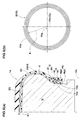
FIG. 2(a) is a side view of a wire wound body according to one embodiment of the present invention. -
FIG. 2(b) is a side view of the wire wound body according to another embodiment of the present invention. -
FIG. 3 is a perspective view illustrating a manufacturing apparatus for manufacturing a pneumatic tire. -
FIG. 4 is a plan view of the manufacturing apparatus for explaining a wire winding step. -
FIG. 5 is a perspective view of the manufacturing apparatus for explaining a wire fixing step. -
FIG. 6(a) is a cross sectional view illustrating the right half of a green tire according to a core molding method. -
FIG. 6(b) is a side view illustrating a conventional wire wound body. - An embodiment of the present invention is described in detail below with reference to the accompanying drawings.
- As shown in
FIG. 1 , a pneumatic tire (hereinafter, it may be simply referred to the "tire") 1 in accordance with the present invention includes atread portion 2, a pair ofsidewall portions 3, a pair ofbead portions 4 each with abead core 5 therein, and acarcass 6 extending betweenbead cores tire 1 in accordance with the present embodiment is embodied as a passenger car tire. Thetire 1 further includes abelt layer 7 disposed radially outward of thecarcass 6 in thetread portion 2, and aninner liner 9 disposed inside thecarcass 6. Theinner liner 9 that is made of an air impermeable rubber forms an inner cavity surface (i) of the tire. -
FIG. 1 illustrates thetire 1 under a standard condition in which thetire 1 is mounted on a standard wheel rim (not shown) and inflated to a standard pressure but no tire load is loaded. - Here, the standard wheel rim is a wheel rim officially approved for the tire by standards organizations, and the standard wheel rim is the "standard rim" specified in JATMA, the "Measuring Rim" in ETRTO, the "Design Rim" in TRA or the like, for example. The standard pressure is a pressure officially approved for the tire by standards organizations, and the standard pressure is the "maximum air pressure" in JATMA, the "Inflation Pressure" in ETRTO, and the maximum pressure given in the "Tire Load Limits at Various Cold Inflation Pressures" table in TRA or the like. However, in case of a passenger car tire, the standard pressure is uniformly defined as 180 kPa.
- The
carcass 6 includes acarcass ply 6A of cords which extends betweenbead cores tread portion 2 andsidewall portions 3. Each of both ends of thecarcass ply 6A terminates at thebead core 5 without being turned up around thebead core 5. The carcass cords are arranged at an angle in a range of from 75 to 90 degrees with respect to a tire equator C. For the carcass cords, an organic fiber cord is employed, for example. - The
belt layer 7 includes at least two belt plies of belt cords laid at an angle in a range of from 15 to 40 degrees with respect to the tire equator C. In this embodiment, thebelt layer 7 includes twobelt plies - The
bead portion 4 is disposed achafer rubber 4 with high hardness for preventing wear due to contact with the wheel rim (not shown). Thechafer rubber 4g in this present embodiment includes an inner portion 4ga extending along the inner cavity surface (i) of the tire, and an outer portion 4gb extending along the bottom of thebead portion 4 and outer surface of thebead portion 4 so as to have a U-shaped cross section. - In order to enhance the rigidity of the
bead portion 4, thebead portion 4 is further disposed aninner apex rubber 8i arranged axially inward of thecarcass 6, and an outer apex rubber 8o arranged axially outward of thecarcass 6. Each of theapex rubber 8i and 8o tapers off to its radially outer end. - The
bead core 5 includes awire wound body 10 in which onebead wire 10a is spirally wound along thecarcass ply 6A. - The
bead core 5 is employed an inner wire wound body 11 arranged axially inward of thecarcass ply 6A, and an outerwire wound body 12 arranged axially outward of thecarcass ply 6A. In this embodiment, each of thewire wound bodies 11 and 12 is configured to a single stack of bead wires in the radial direction of the tire. In another aspect of the invention, each of thewire wound body 11 and 12 may be configured to a plurality of stacks of bead wires, which are laterally and adjacently arranged. Theend portion 6e of thecarcass ply 6A is sandwiched in between the inner wire wound body 11 and the outerwire wound body 12 to be firmly fixed therebetween. In this embodiment, the number of winding of the bead wire in eachwire wound body 11 and 12 are the same. In another aspect of the invention, the number of winding of the bead wire in eachwire wound body 11 and 12 may be different. - As shown in
FIG. 2(a) , thewire wound body 10 is formed by spirally wound onebead wire 10a around awinding center 10c corresponding to the tire rotational axis CL so that a plurality of layers of thebead wire 10a are formed in the radial direction of the tire. - The
wire wound body 10 includes afirst part 13 and a second part 14. Thefirst part 13 includes a plurality of layers of thebead wire 10a each extending in a circumferential direction of the tire having a constant radius R from the tire rotational axis CL. The second part 14 includes a plurality of layers of thebead wire 10a each extending in the circumferential direction of the tire while changing its radius from the tire rotational axis CL. - Since the
wire wound body 10 including thefirst part 13 may have itsgravity center 10g so as to be close to the tire rotational axis CL that corresponds to the windingcenter 10c, better weight uniformity around the tire rotational axis may be offered. - The
first part 13 occupies most of the wire woundbody 10. - Preferably, the second part 14 has the central angle θ1 in a range of from 4 to 20 degrees of the wire wound
body 10. When the central angle θ1 of the second part 14 is excessively small, uniformity of the tire may be deteriorated due to a difficulty in maintaining the shape of the second part 14. When the central angle θ1 of the second part 14 is excessively large, the difference between the windingcenter 10c of the wire woundbody 10 and itsgravity center 10g might become larger. Preferably, the central angle θ1 of the second part 14 is set in a range of not less than 4 degrees, more preferably not less than 8 degrees, but preferably not more than 20 degrees, more preferably not more than 16 degrees. - The second part 14 includes a plurality of layers of the bead wire each radius gradually increasing from a side of a winding-starting
end 10s toward a side of a winding-terminal end 10e of thebead wire 10a. The amount of increase of the radius R of the second part 14 from a side of a winding-startingend 10s toward a side of a winding-terminal end 10e corresponds to a diameter d of thebead wire 10a. - The second part 14 is configured as a straight part 14a that extends in a straight manner between the
end 13e of thefirst part 13 and theend 14e of the second part 14. In another aspect of the present invention, the second part 14 may be configured as an arc part 14b (shown inFIG. 2(b) ) that extends in an arc manner. - In the wire wound body, radially adjacent layers of the
bead wire 10a are arranged so as to come into contact one another. This configuration may be helpful to further reduce the difference between thegravity center 10c of the wire woundbody 10 and the windingcenter 10c. - The wire wound
body 10 has a winding-startingend 10a and a winding-terminal end 10e, and the winding-terminal end 10e is provided with the same position of the winding-startingend 10a in the circumferential direction. Namely, the winding-terminal end 10e is positioned on a radial line that passes both the tire rotational axis CL and the winding-startingend 10s. This configuration may be helpful to further reduce the difference between thegravity center 10c of the wire woundbody 10 and the windingcenter 10c. - The
tire 1 in accordance with the present embodiment is manufactured from agreen tire 1a like the one shown inFIG. 6(a) through a vulcanization process. Hereinafter, the method and apparatus M for manufacturing the tire (green tire 1a) will be described. - As shown in
FIG. 3 , the apparatus M includes an inner core N having an outer surface N1 for molding the inner cavity (i) (shown inFIG. 1 ) of the tire, a driving device Q for rotating the inner core N, and a pasting device P for supplying the bead wire and pasting it directly or indirectly on the outer surface N1 of the inner core N. - The inner core N includes the outer surface N1, and a pair of flanges F each provided on its bead region of the inner core so as to protrude axially outwardly. The outer surface N1 has a three-dimensional shape that corresponds to an inner cavity of the tire under a 5% inflated condition in which the tire is mounted on the standard rim and inflated to a 5% inner pressure of the standard pressure. To obtain the
tire 1 to be manufactured under the 5% inflated condition, thetire 1 is firstly inflated up to the standard pressure and then the inner pressure is reduced down to the 5% of the standard pressure. Preferably, the inner core N may be made of a metallic material or a heat-resistance resin to resist high temperature and pressure during the vulcanization process. - The outer surface N1 of the inner core N includes a pair of a bead molding surfaces Na for molding the
bead portion 4 of the tire. - The driving device Q according to the present embodiment includes an
arm 15 having a L-shape, and a base 16 that rotatably supports thearm 15. Thebase 16 is configured to a rectangular shape, for example. - The
arm 15 is provided with a horizontally extending first supportingaxis 17 at its upper end side, and a vertically extending second supportingaxis 18 at its lower end side. Namely, the second supporting axis is along with the Z-axis. The first supportingaxis 17 supports the inner core N so that the inner core N can rotate around the tire rotational axis CL. The second supportingaxis 18 supports thearm 15 so that thearm 15 can turn around the turning center axis Ca that corresponds to a center of the second supportingaxis 18. The rotational angle of the first supportingaxis 17 and the turning angle of the second supportingaxis 18 are controlled by a computer device based on previously programmed procedures. In this embodiment, the turning center axis Ca passes through a center O of the inner core N at which the tire rotational axis CL and the equatorial plane of the inner core N intersect. - The
base 16 is movably provided along the Y-axis. In this embodiment, thebase 16 is provided on its bottom side with aslider 23a guided on arail 23b extending along the Y-axis. - The pasting device P includes a delivering
roller 19, a pushingroller device 20, and acutting tool 21. The deliveringroller 19 guides thebead wire 10a sent out from the upstream side toward the inner core N through the pushingroller device 20. The pushingroller device 20 pushes thebead wire 10a sent out from the deliveringroller 19 to paste it directly or indirectly on the outer surface N1 of the inner core N. The cuttingtool 21 can cut thebead wire 10a. Thebead wire 10a is previously coated with unvulcanized rubber so that thebead wire 10a is easily stuck on the inner core N. - The delivering
roller 19 may further include a plurality ofguide rollers 19a for removing a temporary unexpected crease such as curl or wave of thebead wire 10a. As shown inFIG.4 , theguide rollers 19a are rotatably supported on abracket 22 and aligned so as to guide thebead wire 10a in a straight manner along the Y-axis. - The pushing
roller device 20 includes aroller 20a that guides thebead wire 10a, and anactuator 20b such as a cylinder actuator that pushes theroller 20a toward the inner core N so as to paste thebead wire 10a thereon. In this embodiment, the equatorial plane of theroller 20a is arranged in the same plane of theequatorial plane 19C of the deliveringroller 19 as shown inFIG. 4 . - The cutting
tool 21 includes acutter 21a that can cut thebead wire 10a by pressing on it, and anactuator device 21b such as a cylinder actuator that can drive thecutter 21a downwardly to cut thebead wire 10a. - Hereinafter, a method for manufacturing the tire using the apparatus M will be described.
- In the method, the inner core N is firstly rotatably attached on the first supporting
axis 17 of the driving device Q. In the initial stage of the method, the pasting device P is positioned away from the inner core N. - Next, the inner portion 4ga of the
chafer rubber 4g and theinner liner 9 which have sticky property are pasted on the outer surface N1 of the inner core N. Then theinner apex rubber 8i is attached on the outer surfaces of thechafer rubber 4g and the inner liner 9 (Shown inFIG. 5 ). In this embodiment, the outer surface of theinner apex rubber 8i includes the predetermined area S1 where thebead wire 10a should be wound. - Next, the bead molding surfaces Na of the inner core N is set its position to face the pushing
roller device 20 of the pasting device P at a predetermined space so that theequatorial plane 19C of the deliveringroller 19 is parallel to the tire rotational axis CL of the inner core N in the top view as shown inFIG. 4 . Furthermore, the rotational axis Cr of theroller 20a is set in a height same as the tire rotational axis CL of the inner core N. - Next, a wire wound body forming step is performed to form the inner wire wound body 11. In this step, the
bead wire 10a is continuously wound on the predetermined area S1 around the windingcenter 10c corresponding to the tire rotational axis CL. - The wire wound body forming step includes a wire fixing step (shown in
FIG. 5 ) in which a winding-startingend 10s of thebead wire 10a is pushed and fixed on the predetermined area S1, and then a wire winding step (shown inFIG. 4 ) in which thebead wire 10a is spirally and continuously wound on the predetermined area S1 by rotating the inner core N around the tire rotational axis CL. - In the wire fixing step, as shown in
FIG. 5 , theactuator 20b of the pushingroller device 20 forces theroller 20a so as to fix the starting-end 10s of the bead wire on the predetermined area S1 of the inner core N. Thus, the starting-end 10s is pasted on the predetermined area S1. In this embodiment, the starting-end 10s of thebead wire 10a is fixed at the radially innermost place 8t of theinner apex rubber 8i. Since theinner apex rubber 8i is an unvulcanized state having sticky property during the wire fixing step, thebead wire 10a may easily be pasted thereon. - The wire winding step alternately includes a first rotating step in which the inner core N is rotated to wind the
bead wire 10a while maintaining an angle α1 in constant between the tire rotational axis CL and the Y-axis direction that is a feeding direction of thebead wire 10a to the internal core N, and a second rotating step in which the inner core N is rotated to wind thebead wire 10a while gradually increasing the angle α1. - Since the angle α1 is maintained substantially constant in the first winding step, the
bead wire 10a is wound at a constant radius R from the tire rotational axis CL. Hence, thefirst part 13 is formed on the predetermined area S1. - As shown in
FIG. 4 , the angle α1 may be increased by turning the inner core N around the turning center axis Ca in a clockwise direction. The winding radius R of thebead wire 10a increases while increasing the angle α1. In the second winding step, the inner core N is rotated around the tire rotational axis CL while gradually increasing the angle α1 by turning the inner core N around the turning center axis Ca. Thus, thebead wire 10a is wound on the predetermined area S1 while increasing its winding radius R. Hence the second part 14 is formed. InFIG. 4 , the inner core N which is under the initial condition of the wire winding step is illustrated by the two-dot chain line. - In the second winding step, when the inner core N is simply turned around the turning center axis Ca, the predetermined area S1 relatively moves toward the
roller 20a, thereby decreasing the distance thereto. In the second winding step in accordance with the present embodiment, the inner core is moved backward along the Y-axis while being turned around the turning-center axis Ca to increase the angle α1. Thus, the distance L between theroller 20a and the predetermined area S1 along the equatorial plane of theroller 20a is maintained constant during second winding step. In this embodiment, thebase 16 is moved along the Y-axis away from the pasting device P to maintain the distance constant. Thus, the second winding step described above may precisely wind thebead wire 10a on the predetermined area S1 of the inner core N without giving unnecessary bend and tension to thebead wire 10a. - As shown in
FIG. 2 , since radially adjacent layers 10a1 and 10a2 ofbead wires 10a are arranged in contact with each other without a gap therebetween, these layers 10a1 and 10a2 are fixed each other to prevent spring-back of thebead wire 10a. Furthermore, such a configuration of layers 10a1 and 10b1 may enhance the strength of the wire wound body 11 such that it may firmly fix thecarcass 6. - Next, a carcass forming step is performed by arranging the
carcass ply 6A axially outward of the inner wire wound body 11. The carcass ply 8A comprises a plurality of radially extending rectangular plies (not shown) that are sequentially arranged in the circumferential direction of the tire. - Again, the wire wound body forming step is performed to form the outer wire wound
body 12 on the predetermined area S2 which is previously decided in an outer surface of thecarcass ply 6A. This step is done by the substantially same way forming the inner wire wound body 11 described above. - After forming the outer wire wound
body 12, the outer apex rubber 8o, the inner portion 4ga of thechafer rubber 4g, thebelt 7, thesidewall rubber 3G, and thetread rubber 2G are attached and assembled on the inner core N to form thegreen tire 1a. Then thegreen tire 1a with the inner core N is vulcanized in a tire mold to manufacture thetire 1 in accordance with present embodiment. Note that thetire 1 in accordance with the present invention is not limited to the one manufactured according to the method described above. - While the particularly preferable embodiments of the present invention have been described in detail, the present invention in not limited to the illustrated embodiments, but can be modified and carried out in various aspects.
- Pneumatic tires of 215/45R17 having the structure of
FIG. 1 except for details shown in Table 1 were made, and tested with respect to its uniformity. Each tire has a bead core formed of the wire wound body shown inFIG. 2(a), FIG. 2(b) orFIG. 6(b) . The test methods are as follows. - In each examples, radial force variation (RFV) on average of 50 tires was measured using a tire uniformity test machine based on the "Method of uniformity test for vehicle tires" defined by JASO C607. The average RFV of each examples is indicated by an index based on Ref.1 being 100. The larger the index, the better the uniformity is.
- Test results are shown in Table 1.
Table 1 Ex. 1 Ex. 2 Ex. 3 Ex. 4 Ex. 5 Ex. 6 Ex. 7 Ex. 8 Ref. 1 Configuration of wire wound body FIG. 2(a) FIG. 2(a) FIG. 2(a) FIG. 2(a) FIG. 2(a) FIG. 2(a) FIG. 2(a) FIG. 2(b) FIG. 6(b) Central angle q1 of second part (deg.) 2 4 7 12 15 20 22 12 - Uniformity RFV (N) 88 82 81 80 81 82 88 79 100 - As the results of the test, it is confirmed that the example tires exhibit better uniformity as compared to the Reference tire. Note that there is no big difference between the tires of
FIG. 2(a) and FIG. 2(b) . -
- 1
- Pneumatic tire
- 2
- Tread portion
- 3
- Sidewall portion
- 4
- Bead portion
- 5
- Bead core
- 6
- Carcass
- 10, 11, 12
- Wire wound body
- 10a
- Bead wire
- 13
- First part
- 14
- Second part
- CL
- Tire rotational axis
- R
- Radius of bead wire
Claims (10)
- A pneumatic tire comprising
a tread portion,
a pair of sidewall portions,
a pair of bead portions each with a bead core therein,
a carcass extending between the bead cores,
at least one of the bead cores comprising a wire wound body in which one bead wire is spirally wound in a continuous around a tire rotational axis so that a plurality of layers of the bead wire are formed in a radial direction of the tire, and
the wire wound body comprising a first part and a second part, the first part comprising a plurality of layers of the bead wire each extending in a circumferential direction of the tire having a constant radius from the tire rotational axis, the second part comprising a plurality of layers of the bead wire each extending in the circumferential direction of the tire while changing its radius from the tire rotational axis. - The pneumatic tire according to claim 1,
wherein the second part constitutes a central angle in a range of from 4 to 20 degrees of the wire wound body. - The pneumatic tire according to claim 2,
wherein the radius of each layer of the bead wire of the second part gradually increases from a side of a winding-starting end toward a side of a winding-terminal end of the bead wire. - The pneumatic tire according to any one of claims 1 to 3,
wherein the at least one of the bead cores comprises an axially inner portion disposed axially inward of the carcass, and an axially outer portion disposed axially outward of the carcass, and each of the axially inner portion and the axially outer portion is configured as the wire wound body. - The pneumatic tire according to any one of claims 1 to 4,
wherein each layer of the bead wire of the second part extends in a straight manner. - The pneumatic tire according to any one of claims 1 to 4,
wherein each layer of the bead wire of the second part extends in an arc manner. - The pneumatic tire according to any one of claims 1 to 6,
wherein the wire wound body has a winding-starting end and a winding-terminal end, and
the winding-terminal end is positioned on a radial line that passes through the tire rotational axis and the winding-starting end. - A method for manufacturing the pneumatic tire according to any one of claims 1 to 7, the method comprising
a wire wound body forming step in which one bead wire is spirally wound in
a continuous on a predetermined area of a side surface of an inner core to form the wire wound body,
wherein the wire wound body forming step comprises
a wire fixing step in which a winding-starting end of the bead wire
is pushed and fixed on the predetermined area, and then a wire winding step in which the bead wire is spirally wound on
the predetermined area by rotating the inner core around the tire rotational axis,
wherein the wire winding step comprises
a first rotating step in which the inner core rotates to wind the bead
wire while maintaining an angle α1 in constant between the tire rotational axis and a Y-axis direction that is a feeding direction of the bead wire to the inner core , and
a second rotating step in which the inner core rotates to wind the bead wire while gradually increasing the angle α1. - The method for manufacturing the pneumatic tire according to claim 8,
wherein the angle α1 is increased by turning the inner core around a radial axis passing through a point "O" at which a core equatorial plane and the tire rotational axis intersect. - The method for manufacturing the pneumatic tire according to claim 8 or 9,
wherein the second rotating step further comprises moving the inner core backward along the Y-axis while increasing the angle α1.
Applications Claiming Priority (2)
| Application Number | Priority Date | Filing Date | Title |
|---|---|---|---|
| JP2011274779 | 2011-12-15 | ||
| PCT/JP2012/080311 WO2013088936A1 (en) | 2011-12-15 | 2012-11-22 | Pneumatic tyre and manufacturing method therefor |
Publications (3)
| Publication Number | Publication Date |
|---|---|
| EP2767416A1 true EP2767416A1 (en) | 2014-08-20 |
| EP2767416A4 EP2767416A4 (en) | 2015-06-17 |
| EP2767416B1 EP2767416B1 (en) | 2017-11-15 |
Family
ID=48612391
Family Applications (1)
| Application Number | Title | Priority Date | Filing Date |
|---|---|---|---|
| EP12857840.8A Active EP2767416B1 (en) | 2011-12-15 | 2012-11-22 | Pneumatic tyre and manufacturing method therefor |
Country Status (6)
| Country | Link |
|---|---|
| US (2) | US20150053326A1 (en) |
| EP (1) | EP2767416B1 (en) |
| JP (2) | JP6034803B2 (en) |
| CN (1) | CN104010844B (en) |
| BR (1) | BR112014014570B1 (en) |
| WO (1) | WO2013088936A1 (en) |
Cited By (1)
| Publication number | Priority date | Publication date | Assignee | Title |
|---|---|---|---|---|
| FR3030348A1 (en) * | 2014-12-23 | 2016-06-24 | Michelin & Cie | METHOD FOR ASSEMBLING PNEUMATIC BRAKE |
Families Citing this family (3)
| Publication number | Priority date | Publication date | Assignee | Title |
|---|---|---|---|---|
| JP6074230B2 (en) * | 2012-11-09 | 2017-02-01 | 住友ゴム工業株式会社 | Pneumatic tire and manufacturing method thereof |
| JP7245632B2 (en) * | 2018-10-31 | 2023-03-24 | 株式会社ブリヂストン | tire |
| FR3105097A1 (en) * | 2019-12-19 | 2021-06-25 | Compagnie Generale Des Etablissements Michelin | Pneumatic including an improved bead |
Family Cites Families (21)
| Publication number | Priority date | Publication date | Assignee | Title |
|---|---|---|---|---|
| US3170662A (en) * | 1961-09-29 | 1965-02-23 | Goodyear Tire & Rubber | Tire bead grommet and method of making same |
| US4219375A (en) * | 1978-10-26 | 1980-08-26 | The Goodyear Tire & Rubber Company | Making bead rings for vehicle tires |
| US5099902A (en) * | 1989-05-30 | 1992-03-31 | Bridgestone/Firestone, Inc. | Offset wound helical bead for pneumatic tires |
| CA2013329A1 (en) * | 1989-05-30 | 1990-11-30 | Louis W. Shurman | Offset wound helical bead for pneumatic tires |
| EP0467277A1 (en) * | 1990-07-19 | 1992-01-22 | Bridgestone/Firestone, Inc. | Bead construction for radial pneumatic tires |
| JPH0585111A (en) * | 1991-09-26 | 1993-04-06 | Bridgestone Corp | Bead core of pneumatic tire |
| JPH0616018A (en) * | 1992-06-30 | 1994-01-25 | Bridgestone Corp | Pneumatic tire |
| US5660656A (en) * | 1992-08-05 | 1997-08-26 | Sedepro | Tire with anchored carcass |
| JPH06156024A (en) * | 1992-11-26 | 1994-06-03 | Sumitomo Rubber Ind Ltd | Bead core of tire for passenger car |
| JP4073068B2 (en) * | 1997-12-10 | 2008-04-09 | 株式会社ブリヂストン | Pneumatic tire |
| WO2001043957A1 (en) * | 1999-12-15 | 2001-06-21 | Pirelli Pneumatici S.P.A. | A method for manufacturing reinforcing annular elements for vehicle tyres, and a tyre incorporating inextensible annular inserts manufactured by such a method |
| JP2003146027A (en) * | 2001-11-13 | 2003-05-21 | Bridgestone Corp | Bead core intermediate, and manufacturing method of and device for the same |
| JP4488792B2 (en) * | 2004-05-24 | 2010-06-23 | 株式会社ブリヂストン | Pneumatic tire manufacturing method |
| JP4268564B2 (en) * | 2004-05-27 | 2009-05-27 | 住友ゴム工業株式会社 | Pneumatic tire |
| JP4695429B2 (en) | 2004-11-11 | 2011-06-08 | 住友ゴム工業株式会社 | Pneumatic tire and manufacturing method thereof |
| JP2007030299A (en) * | 2005-07-26 | 2007-02-08 | Bridgestone Corp | Wire arranging method by pitch feed roller |
| JP2009143277A (en) * | 2007-12-11 | 2009-07-02 | Bridgestone Corp | Pneumatic tire |
| JP2010000827A (en) * | 2008-06-18 | 2010-01-07 | Bridgestone Corp | Bead core for tire, pneumatic tire, and manufacturing method of bead core for tire |
| DE102008049314A1 (en) * | 2008-09-29 | 2010-04-01 | Continental Reifen Deutschland Gmbh | Vehicle tires |
| JP5351675B2 (en) * | 2009-09-10 | 2013-11-27 | 不二精工株式会社 | Bead core for pneumatic tire and pneumatic tire using the bead core |
| JP4605305B2 (en) * | 2010-02-19 | 2011-01-05 | 日本軽金属株式会社 | Pellicle frame |
-
2012
- 2012-11-22 WO PCT/JP2012/080311 patent/WO2013088936A1/en not_active Ceased
- 2012-11-22 US US14/356,532 patent/US20150053326A1/en not_active Abandoned
- 2012-11-22 CN CN201280062228.2A patent/CN104010844B/en active Active
- 2012-11-22 EP EP12857840.8A patent/EP2767416B1/en active Active
- 2012-11-22 JP JP2013549190A patent/JP6034803B2/en active Active
- 2012-11-22 BR BR112014014570-9A patent/BR112014014570B1/en active IP Right Grant
-
2016
- 2016-09-26 JP JP2016186914A patent/JP6205040B2/en active Active
-
2017
- 2017-06-23 US US15/631,507 patent/US10894376B2/en not_active Expired - Fee Related
Cited By (3)
| Publication number | Priority date | Publication date | Assignee | Title |
|---|---|---|---|---|
| FR3030348A1 (en) * | 2014-12-23 | 2016-06-24 | Michelin & Cie | METHOD FOR ASSEMBLING PNEUMATIC BRAKE |
| WO2016102615A1 (en) * | 2014-12-23 | 2016-06-30 | Compagnie Generale Des Etablissements Michelin | Method for assembling a tyre blank |
| US20170348932A1 (en) * | 2014-12-23 | 2017-12-07 | Compagnie Generale Des Etablissements Michelin | Method for assembling a tire blank |
Also Published As
| Publication number | Publication date |
|---|---|
| US20150053326A1 (en) | 2015-02-26 |
| CN104010844A (en) | 2014-08-27 |
| CN104010844B (en) | 2017-04-26 |
| JP6034803B2 (en) | 2016-11-30 |
| JP2016216044A (en) | 2016-12-22 |
| US10894376B2 (en) | 2021-01-19 |
| WO2013088936A1 (en) | 2013-06-20 |
| JPWO2013088936A1 (en) | 2015-04-27 |
| US20170282473A1 (en) | 2017-10-05 |
| EP2767416B1 (en) | 2017-11-15 |
| BR112014014570B1 (en) | 2020-08-11 |
| JP6205040B2 (en) | 2017-09-27 |
| EP2767416A4 (en) | 2015-06-17 |
| BR112014014570A2 (en) | 2017-06-13 |
Similar Documents
| Publication | Publication Date | Title |
|---|---|---|
| JP4695429B2 (en) | Pneumatic tire and manufacturing method thereof | |
| US8845836B2 (en) | Geodesic tire and method of manufacture | |
| US10894376B2 (en) | Pneumatic tire and manufacturing method therefor | |
| US20110146876A1 (en) | Geodesic belted tire | |
| CN100480065C (en) | Tire for use in a two-wheeled motor vehicle and method for manufacturing the same | |
| WO2009157028A1 (en) | Process and plant for building tyres for vehicle wheels | |
| JP5255635B2 (en) | Tire manufacturing method and apparatus | |
| EP2607065B1 (en) | Pneumatic tire and manufacturing method of the same | |
| JP4263755B1 (en) | Pneumatic tire manufacturing method | |
| EP3205489A1 (en) | Pneumatic tire manufacturing method, and pneumatic tire | |
| CN103889699A (en) | Method for manufacturing pneumatic tire | |
| EP2561980B1 (en) | Tire production method | |
| EP1800845B1 (en) | Pneumatic tire and method of manufacturing the same | |
| JP5200124B2 (en) | Pneumatic tire manufacturing method | |
| JP5193278B2 (en) | Pneumatic tire | |
| EP4427944B1 (en) | Tire and production method for tire | |
| JP7642998B2 (en) | Tire, tire manufacturing method, and tire design method | |
| CN116568493A (en) | Tyre and method for manufacturing the same |
Legal Events
| Date | Code | Title | Description |
|---|---|---|---|
| PUAI | Public reference made under article 153(3) epc to a published international application that has entered the european phase |
Free format text: ORIGINAL CODE: 0009012 |
|
| 17P | Request for examination filed |
Effective date: 20140515 |
|
| AK | Designated contracting states |
Kind code of ref document: A1 Designated state(s): AL AT BE BG CH CY CZ DE DK EE ES FI FR GB GR HR HU IE IS IT LI LT LU LV MC MK MT NL NO PL PT RO RS SE SI SK SM TR |
|
| DAX | Request for extension of the european patent (deleted) | ||
| RA4 | Supplementary search report drawn up and despatched (corrected) |
Effective date: 20150515 |
|
| RIC1 | Information provided on ipc code assigned before grant |
Ipc: B60C 15/00 20060101ALI20150508BHEP Ipc: B60C 15/04 20060101AFI20150508BHEP |
|
| REG | Reference to a national code |
Ref country code: DE Ref legal event code: R079 Ref document number: 602012039939 Country of ref document: DE Free format text: PREVIOUS MAIN CLASS: B60C0015040000 Ipc: B29D0030480000 |
|
| GRAP | Despatch of communication of intention to grant a patent |
Free format text: ORIGINAL CODE: EPIDOSNIGR1 |
|
| STAA | Information on the status of an ep patent application or granted ep patent |
Free format text: STATUS: GRANT OF PATENT IS INTENDED |
|
| RIC1 | Information provided on ipc code assigned before grant |
Ipc: B29K 305/00 20060101ALI20170511BHEP Ipc: B29D 30/48 20060101AFI20170511BHEP Ipc: B29D 30/34 20060101ALI20170511BHEP Ipc: B60C 15/04 20060101ALI20170511BHEP Ipc: B60C 15/00 20060101ALI20170511BHEP Ipc: B60C 15/05 20060101ALI20170511BHEP |
|
| INTG | Intention to grant announced |
Effective date: 20170529 |
|
| GRAS | Grant fee paid |
Free format text: ORIGINAL CODE: EPIDOSNIGR3 |
|
| GRAA | (expected) grant |
Free format text: ORIGINAL CODE: 0009210 |
|
| STAA | Information on the status of an ep patent application or granted ep patent |
Free format text: STATUS: THE PATENT HAS BEEN GRANTED |
|
| AK | Designated contracting states |
Kind code of ref document: B1 Designated state(s): AL AT BE BG CH CY CZ DE DK EE ES FI FR GB GR HR HU IE IS IT LI LT LU LV MC MK MT NL NO PL PT RO RS SE SI SK SM TR |
|
| REG | Reference to a national code |
Ref country code: CH Ref legal event code: EP Ref country code: GB Ref legal event code: FG4D Ref country code: AT Ref legal event code: REF Ref document number: 945846 Country of ref document: AT Kind code of ref document: T Effective date: 20171115 |
|
| REG | Reference to a national code |
Ref country code: FR Ref legal event code: PLFP Year of fee payment: 6 |
|
| REG | Reference to a national code |
Ref country code: IE Ref legal event code: FG4D |
|
| REG | Reference to a national code |
Ref country code: DE Ref legal event code: R096 Ref document number: 602012039939 Country of ref document: DE |
|
| REG | Reference to a national code |
Ref country code: NL Ref legal event code: MP Effective date: 20171115 |
|
| REG | Reference to a national code |
Ref country code: LT Ref legal event code: MG4D |
|
| REG | Reference to a national code |
Ref country code: AT Ref legal event code: MK05 Ref document number: 945846 Country of ref document: AT Kind code of ref document: T Effective date: 20171115 |
|
| PG25 | Lapsed in a contracting state [announced via postgrant information from national office to epo] |
Ref country code: NL Free format text: LAPSE BECAUSE OF FAILURE TO SUBMIT A TRANSLATION OF THE DESCRIPTION OR TO PAY THE FEE WITHIN THE PRESCRIBED TIME-LIMIT Effective date: 20171115 Ref country code: LT Free format text: LAPSE BECAUSE OF FAILURE TO SUBMIT A TRANSLATION OF THE DESCRIPTION OR TO PAY THE FEE WITHIN THE PRESCRIBED TIME-LIMIT Effective date: 20171115 Ref country code: SE Free format text: LAPSE BECAUSE OF FAILURE TO SUBMIT A TRANSLATION OF THE DESCRIPTION OR TO PAY THE FEE WITHIN THE PRESCRIBED TIME-LIMIT Effective date: 20171115 Ref country code: FI Free format text: LAPSE BECAUSE OF FAILURE TO SUBMIT A TRANSLATION OF THE DESCRIPTION OR TO PAY THE FEE WITHIN THE PRESCRIBED TIME-LIMIT Effective date: 20171115 Ref country code: ES Free format text: LAPSE BECAUSE OF FAILURE TO SUBMIT A TRANSLATION OF THE DESCRIPTION OR TO PAY THE FEE WITHIN THE PRESCRIBED TIME-LIMIT Effective date: 20171115 Ref country code: NO Free format text: LAPSE BECAUSE OF FAILURE TO SUBMIT A TRANSLATION OF THE DESCRIPTION OR TO PAY THE FEE WITHIN THE PRESCRIBED TIME-LIMIT Effective date: 20180215 |
|
| PG25 | Lapsed in a contracting state [announced via postgrant information from national office to epo] |
Ref country code: GR Free format text: LAPSE BECAUSE OF FAILURE TO SUBMIT A TRANSLATION OF THE DESCRIPTION OR TO PAY THE FEE WITHIN THE PRESCRIBED TIME-LIMIT Effective date: 20180216 Ref country code: AT Free format text: LAPSE BECAUSE OF FAILURE TO SUBMIT A TRANSLATION OF THE DESCRIPTION OR TO PAY THE FEE WITHIN THE PRESCRIBED TIME-LIMIT Effective date: 20171115 Ref country code: LV Free format text: LAPSE BECAUSE OF FAILURE TO SUBMIT A TRANSLATION OF THE DESCRIPTION OR TO PAY THE FEE WITHIN THE PRESCRIBED TIME-LIMIT Effective date: 20171115 Ref country code: BG Free format text: LAPSE BECAUSE OF FAILURE TO SUBMIT A TRANSLATION OF THE DESCRIPTION OR TO PAY THE FEE WITHIN THE PRESCRIBED TIME-LIMIT Effective date: 20180215 Ref country code: RS Free format text: LAPSE BECAUSE OF FAILURE TO SUBMIT A TRANSLATION OF THE DESCRIPTION OR TO PAY THE FEE WITHIN THE PRESCRIBED TIME-LIMIT Effective date: 20171115 Ref country code: HR Free format text: LAPSE BECAUSE OF FAILURE TO SUBMIT A TRANSLATION OF THE DESCRIPTION OR TO PAY THE FEE WITHIN THE PRESCRIBED TIME-LIMIT Effective date: 20171115 |
|
| PG25 | Lapsed in a contracting state [announced via postgrant information from national office to epo] |
Ref country code: EE Free format text: LAPSE BECAUSE OF FAILURE TO SUBMIT A TRANSLATION OF THE DESCRIPTION OR TO PAY THE FEE WITHIN THE PRESCRIBED TIME-LIMIT Effective date: 20171115 Ref country code: CY Free format text: LAPSE BECAUSE OF FAILURE TO SUBMIT A TRANSLATION OF THE DESCRIPTION OR TO PAY THE FEE WITHIN THE PRESCRIBED TIME-LIMIT Effective date: 20171115 Ref country code: SK Free format text: LAPSE BECAUSE OF FAILURE TO SUBMIT A TRANSLATION OF THE DESCRIPTION OR TO PAY THE FEE WITHIN THE PRESCRIBED TIME-LIMIT Effective date: 20171115 Ref country code: CZ Free format text: LAPSE BECAUSE OF FAILURE TO SUBMIT A TRANSLATION OF THE DESCRIPTION OR TO PAY THE FEE WITHIN THE PRESCRIBED TIME-LIMIT Effective date: 20171115 Ref country code: CH Free format text: LAPSE BECAUSE OF NON-PAYMENT OF DUE FEES Effective date: 20171130 Ref country code: DK Free format text: LAPSE BECAUSE OF FAILURE TO SUBMIT A TRANSLATION OF THE DESCRIPTION OR TO PAY THE FEE WITHIN THE PRESCRIBED TIME-LIMIT Effective date: 20171115 Ref country code: LI Free format text: LAPSE BECAUSE OF NON-PAYMENT OF DUE FEES Effective date: 20171130 |
|
| REG | Reference to a national code |
Ref country code: DE Ref legal event code: R097 Ref document number: 602012039939 Country of ref document: DE |
|
| PG25 | Lapsed in a contracting state [announced via postgrant information from national office to epo] |
Ref country code: PL Free format text: LAPSE BECAUSE OF FAILURE TO SUBMIT A TRANSLATION OF THE DESCRIPTION OR TO PAY THE FEE WITHIN THE PRESCRIBED TIME-LIMIT Effective date: 20171115 Ref country code: RO Free format text: LAPSE BECAUSE OF FAILURE TO SUBMIT A TRANSLATION OF THE DESCRIPTION OR TO PAY THE FEE WITHIN THE PRESCRIBED TIME-LIMIT Effective date: 20171115 Ref country code: LU Free format text: LAPSE BECAUSE OF NON-PAYMENT OF DUE FEES Effective date: 20171122 Ref country code: IT Free format text: LAPSE BECAUSE OF FAILURE TO SUBMIT A TRANSLATION OF THE DESCRIPTION OR TO PAY THE FEE WITHIN THE PRESCRIBED TIME-LIMIT Effective date: 20171115 Ref country code: SM Free format text: LAPSE BECAUSE OF FAILURE TO SUBMIT A TRANSLATION OF THE DESCRIPTION OR TO PAY THE FEE WITHIN THE PRESCRIBED TIME-LIMIT Effective date: 20171115 |
|
| REG | Reference to a national code |
Ref country code: BE Ref legal event code: MM Effective date: 20171130 |
|
| REG | Reference to a national code |
Ref country code: IE Ref legal event code: MM4A |
|
| PLBE | No opposition filed within time limit |
Free format text: ORIGINAL CODE: 0009261 |
|
| STAA | Information on the status of an ep patent application or granted ep patent |
Free format text: STATUS: NO OPPOSITION FILED WITHIN TIME LIMIT |
|
| PG25 | Lapsed in a contracting state [announced via postgrant information from national office to epo] |
Ref country code: MT Free format text: LAPSE BECAUSE OF NON-PAYMENT OF DUE FEES Effective date: 20171122 |
|
| REG | Reference to a national code |
Ref country code: FR Ref legal event code: PLFP Year of fee payment: 7 |
|
| 26N | No opposition filed |
Effective date: 20180817 |
|
| GBPC | Gb: european patent ceased through non-payment of renewal fee |
Effective date: 20180215 |
|
| PG25 | Lapsed in a contracting state [announced via postgrant information from national office to epo] |
Ref country code: IE Free format text: LAPSE BECAUSE OF NON-PAYMENT OF DUE FEES Effective date: 20171122 |
|
| PG25 | Lapsed in a contracting state [announced via postgrant information from national office to epo] |
Ref country code: BE Free format text: LAPSE BECAUSE OF NON-PAYMENT OF DUE FEES Effective date: 20171130 Ref country code: SI Free format text: LAPSE BECAUSE OF FAILURE TO SUBMIT A TRANSLATION OF THE DESCRIPTION OR TO PAY THE FEE WITHIN THE PRESCRIBED TIME-LIMIT Effective date: 20171115 |
|
| PG25 | Lapsed in a contracting state [announced via postgrant information from national office to epo] |
Ref country code: GB Free format text: LAPSE BECAUSE OF NON-PAYMENT OF DUE FEES Effective date: 20180215 |
|
| PG25 | Lapsed in a contracting state [announced via postgrant information from national office to epo] |
Ref country code: HU Free format text: LAPSE BECAUSE OF FAILURE TO SUBMIT A TRANSLATION OF THE DESCRIPTION OR TO PAY THE FEE WITHIN THE PRESCRIBED TIME-LIMIT; INVALID AB INITIO Effective date: 20121122 Ref country code: MC Free format text: LAPSE BECAUSE OF FAILURE TO SUBMIT A TRANSLATION OF THE DESCRIPTION OR TO PAY THE FEE WITHIN THE PRESCRIBED TIME-LIMIT Effective date: 20171115 |
|
| PG25 | Lapsed in a contracting state [announced via postgrant information from national office to epo] |
Ref country code: MK Free format text: LAPSE BECAUSE OF FAILURE TO SUBMIT A TRANSLATION OF THE DESCRIPTION OR TO PAY THE FEE WITHIN THE PRESCRIBED TIME-LIMIT Effective date: 20171115 |
|
| PG25 | Lapsed in a contracting state [announced via postgrant information from national office to epo] |
Ref country code: TR Free format text: LAPSE BECAUSE OF FAILURE TO SUBMIT A TRANSLATION OF THE DESCRIPTION OR TO PAY THE FEE WITHIN THE PRESCRIBED TIME-LIMIT Effective date: 20171115 |
|
| PG25 | Lapsed in a contracting state [announced via postgrant information from national office to epo] |
Ref country code: PT Free format text: LAPSE BECAUSE OF FAILURE TO SUBMIT A TRANSLATION OF THE DESCRIPTION OR TO PAY THE FEE WITHIN THE PRESCRIBED TIME-LIMIT Effective date: 20171115 |
|
| PG25 | Lapsed in a contracting state [announced via postgrant information from national office to epo] |
Ref country code: AL Free format text: LAPSE BECAUSE OF FAILURE TO SUBMIT A TRANSLATION OF THE DESCRIPTION OR TO PAY THE FEE WITHIN THE PRESCRIBED TIME-LIMIT Effective date: 20171115 Ref country code: IS Free format text: LAPSE BECAUSE OF FAILURE TO SUBMIT A TRANSLATION OF THE DESCRIPTION OR TO PAY THE FEE WITHIN THE PRESCRIBED TIME-LIMIT Effective date: 20180315 |
|
| P01 | Opt-out of the competence of the unified patent court (upc) registered |
Effective date: 20230510 |
|
| PGFP | Annual fee paid to national office [announced via postgrant information from national office to epo] |
Ref country code: FR Payment date: 20250930 Year of fee payment: 14 |
|
| PGFP | Annual fee paid to national office [announced via postgrant information from national office to epo] |
Ref country code: DE Payment date: 20250930 Year of fee payment: 14 |