EP2767413A2 - Heavy duty pneumatic tire - Google Patents
Heavy duty pneumatic tire Download PDFInfo
- Publication number
- EP2767413A2 EP2767413A2 EP14153593.0A EP14153593A EP2767413A2 EP 2767413 A2 EP2767413 A2 EP 2767413A2 EP 14153593 A EP14153593 A EP 14153593A EP 2767413 A2 EP2767413 A2 EP 2767413A2
- Authority
- EP
- European Patent Office
- Prior art keywords
- groove
- tire
- grooves
- lateral grooves
- middle lateral
- Prior art date
- Legal status (The legal status is an assumption and is not a legal conclusion. Google has not performed a legal analysis and makes no representation as to the accuracy of the status listed.)
- Granted
Links
Images


Classifications
-
- B—PERFORMING OPERATIONS; TRANSPORTING
- B60—VEHICLES IN GENERAL
- B60C—VEHICLE TYRES; TYRE INFLATION; TYRE CHANGING; CONNECTING VALVES TO INFLATABLE ELASTIC BODIES IN GENERAL; DEVICES OR ARRANGEMENTS RELATED TO TYRES
- B60C11/00—Tyre tread bands; Tread patterns; Anti-skid inserts
- B60C11/03—Tread patterns
- B60C11/0306—Patterns comprising block rows or discontinuous ribs
-
- B—PERFORMING OPERATIONS; TRANSPORTING
- B60—VEHICLES IN GENERAL
- B60C—VEHICLE TYRES; TYRE INFLATION; TYRE CHANGING; CONNECTING VALVES TO INFLATABLE ELASTIC BODIES IN GENERAL; DEVICES OR ARRANGEMENTS RELATED TO TYRES
- B60C11/00—Tyre tread bands; Tread patterns; Anti-skid inserts
- B60C11/03—Tread patterns
- B60C11/12—Tread patterns characterised by the use of narrow slits or incisions, e.g. sipes
- B60C11/1236—Tread patterns characterised by the use of narrow slits or incisions, e.g. sipes with special arrangements in the tread pattern
- B60C11/125—Tread patterns characterised by the use of narrow slits or incisions, e.g. sipes with special arrangements in the tread pattern arranged at the groove bottom
-
- B—PERFORMING OPERATIONS; TRANSPORTING
- B60—VEHICLES IN GENERAL
- B60C—VEHICLE TYRES; TYRE INFLATION; TYRE CHANGING; CONNECTING VALVES TO INFLATABLE ELASTIC BODIES IN GENERAL; DEVICES OR ARRANGEMENTS RELATED TO TYRES
- B60C11/00—Tyre tread bands; Tread patterns; Anti-skid inserts
- B60C11/03—Tread patterns
- B60C11/12—Tread patterns characterised by the use of narrow slits or incisions, e.g. sipes
- B60C11/1259—Depth of the sipe
- B60C11/1263—Depth of the sipe different within the same sipe
-
- B—PERFORMING OPERATIONS; TRANSPORTING
- B60—VEHICLES IN GENERAL
- B60C—VEHICLE TYRES; TYRE INFLATION; TYRE CHANGING; CONNECTING VALVES TO INFLATABLE ELASTIC BODIES IN GENERAL; DEVICES OR ARRANGEMENTS RELATED TO TYRES
- B60C11/00—Tyre tread bands; Tread patterns; Anti-skid inserts
- B60C11/03—Tread patterns
- B60C11/13—Tread patterns characterised by the groove cross-section, e.g. for buttressing or preventing stone-trapping
- B60C11/1369—Tie bars for linking block elements and bridging the groove
-
- B—PERFORMING OPERATIONS; TRANSPORTING
- B60—VEHICLES IN GENERAL
- B60C—VEHICLE TYRES; TYRE INFLATION; TYRE CHANGING; CONNECTING VALVES TO INFLATABLE ELASTIC BODIES IN GENERAL; DEVICES OR ARRANGEMENTS RELATED TO TYRES
- B60C11/00—Tyre tread bands; Tread patterns; Anti-skid inserts
- B60C11/03—Tread patterns
- B60C2011/0337—Tread patterns characterised by particular design features of the pattern
- B60C2011/0339—Grooves
- B60C2011/0341—Circumferential grooves
- B60C2011/0346—Circumferential grooves with zigzag shape
-
- B—PERFORMING OPERATIONS; TRANSPORTING
- B60—VEHICLES IN GENERAL
- B60C—VEHICLE TYRES; TYRE INFLATION; TYRE CHANGING; CONNECTING VALVES TO INFLATABLE ELASTIC BODIES IN GENERAL; DEVICES OR ARRANGEMENTS RELATED TO TYRES
- B60C11/00—Tyre tread bands; Tread patterns; Anti-skid inserts
- B60C11/03—Tread patterns
- B60C2011/0337—Tread patterns characterised by particular design features of the pattern
- B60C2011/0339—Grooves
- B60C2011/0358—Lateral grooves, i.e. having an angle of 45 to 90 degees to the equatorial plane
- B60C2011/0367—Lateral grooves, i.e. having an angle of 45 to 90 degees to the equatorial plane characterised by depth
- B60C2011/0369—Lateral grooves, i.e. having an angle of 45 to 90 degees to the equatorial plane characterised by depth with varying depth of the groove
-
- B—PERFORMING OPERATIONS; TRANSPORTING
- B60—VEHICLES IN GENERAL
- B60C—VEHICLE TYRES; TYRE INFLATION; TYRE CHANGING; CONNECTING VALVES TO INFLATABLE ELASTIC BODIES IN GENERAL; DEVICES OR ARRANGEMENTS RELATED TO TYRES
- B60C11/00—Tyre tread bands; Tread patterns; Anti-skid inserts
- B60C11/03—Tread patterns
- B60C2011/0337—Tread patterns characterised by particular design features of the pattern
- B60C2011/0339—Grooves
- B60C2011/0374—Slant grooves, i.e. having an angle of about 5 to 35 degrees to the equatorial plane
- B60C2011/0379—Slant grooves, i.e. having an angle of about 5 to 35 degrees to the equatorial plane characterised by depth
-
- B—PERFORMING OPERATIONS; TRANSPORTING
- B60—VEHICLES IN GENERAL
- B60C—VEHICLE TYRES; TYRE INFLATION; TYRE CHANGING; CONNECTING VALVES TO INFLATABLE ELASTIC BODIES IN GENERAL; DEVICES OR ARRANGEMENTS RELATED TO TYRES
- B60C2200/00—Tyres specially adapted for particular applications
- B60C2200/06—Tyres specially adapted for particular applications for heavy duty vehicles
-
- Y—GENERAL TAGGING OF NEW TECHNOLOGICAL DEVELOPMENTS; GENERAL TAGGING OF CROSS-SECTIONAL TECHNOLOGIES SPANNING OVER SEVERAL SECTIONS OF THE IPC; TECHNICAL SUBJECTS COVERED BY FORMER USPC CROSS-REFERENCE ART COLLECTIONS [XRACs] AND DIGESTS
- Y02—TECHNOLOGIES OR APPLICATIONS FOR MITIGATION OR ADAPTATION AGAINST CLIMATE CHANGE
- Y02T—CLIMATE CHANGE MITIGATION TECHNOLOGIES RELATED TO TRANSPORTATION
- Y02T10/00—Road transport of goods or passengers
- Y02T10/80—Technologies aiming to reduce greenhouse gasses emissions common to all road transportation technologies
- Y02T10/86—Optimisation of rolling resistance, e.g. weight reduction
Definitions
- the present invention relates to a heavy duty pneumatic tire that offers low rolling resistance while maintaining wet performance as well as anti-stone-biting performance.
- Japanese Unexamined Patent Application Publication No. 2006-341769 discloses a pneumatic tire having a tread portion with a high land ratio in its central region for reducing energy loss of tread rubber by preventing large deformation of the central region.
- the present invention has been worked out in light of the circumstances described above, and has a main object of providing a heavy duty pneumatic tire that offers low rolling resistance while maintaining wet performance as well as anti-stone-biting performance.
- a heavy duty pneumatic tire includes a tread portion provided with a plurality of circumferentially and continuously extending main grooves that include a pair of shoulder main grooves disposed axially outermost side, and at least one center main groove disposed between the shoulder main grooves, and the tread portion including a pair of middle portions each of which is between the shoulder main groove and the center main groove.
- Each middle portion is provided with a circumferentially and continuously extending middle sub groove, a plurality of axially outer middle lateral grooves extending from the middle sub groove to the shoulder main groove, and a plurality of axially inner middle lateral grooves extending from the middle sub groove toward the center main groove.
- the outer middle lateral grooves and the inner middle lateral grooves are inclined at angle with respect to an axial direction of the tire with the same direction.
- the respective number of outer middle lateral grooves and the inner middle lateral grooves are in a range of from 40 to 50 in each middle portion.
- Each of the outer middle lateral grooves and the inner middle lateral grooves includes a shallow bottom part having a depth smaller than that of the shoulder main grooves and the center main groove.
- the shallow bottom part is provided with a groove bottom sipe extending along a longitudinal direction of each lateral groove, and the groove bottom sipe includes a first portion having a depth from a top surface of the middle portion to its bottom in a range of from 0.85 to 1.0 times in relation to a depth of the center main groove, and a second portion having a depth from a top surface of the shallow bottom part to its bottom in a range of from 0.30 to 0.70 times in relation to a depth from a top surface of the shallow bottom part to a bottom of the first portion.
- the middle sub groove may be configured to a zigzag form that includes a first inclined element and a second inclined element inclined an opposite direction with respect to the first inclined element and having a circumferential length longer than that of the first inclined element.
- the middle portion may include a plurality of outer middle blocks between the outer middle lateral grooves, and each outer middle block has a circumferential length in a range of from 0.50 to 0.80 times in relation to a maximum circumferential ground contact length of the tread portion under a standard loaded condition in which the tire is mounted on a standard wheel rim with a standard pressure and is loaded with a standard tire load at a camber angle of zero.
- the first portion of the groove bottom sipe may have a longitudinal length in a range of from 0.20 to 0.40 times the whole length of the groove bottom sipe.
- the groove bottom sipe may include the first portion and second portion alternately arranged in a circumferential direction of the tire.
- a heavy duty pneumatic tire 1 for trucks or busses in accordance with the present invention comprises a tread portion 2 provided with a plurality of circumferentially and continuously extending main grooves that include a pair of shoulder main grooves 3 and 3 disposed axially outermost side and at least one, preferably a pair of center main grooves 4 and 4 disposed between the shoulder main grooves 3 and 3.
- the tread portion 2 is separated into a plurality of land portions that include a central portion 5 between the center main grooves 4 and 4, and a pair of middle portions 6 and 6 between adjacent center main groove 3 and shoulder main groove 4.
- the tread portion 2 includes a pair of tread edges Te and Te.
- the tread edge Te is defined as an axially outer edge in a ground contact patch of the tread portion under a standard loaded condition in which the tire 1 is mounted on a standard wheel rim with a standard pressure and is loaded with a standard tire load at a camber angle of set to zero.
- a tread width TW shown in FIG. 1 is an axial distance between the tread edges Te and Te under a standard unloaded condition in which the tire 1 is mounted on the standard wheel rim with the standard pressure and is loaded with no tire load.
- various dimensions, positions and the like of the tire refer to those under the standard unloaded condition of the tire unless otherwise noted.
- the standard wheel rim is a wheel rim officially approved or recommended for the tire by standards organizations, i.e. JATMA, TRA, ETRTO, and the like which are effective in the area where the tire is manufactured, sold or used.
- the standard wheel rim is the "standard rim” specified in JATMA, the "Measuring Rim” in ETRTO, and the "Design Rim” in TRA or the like.
- the standard pressure and the standard tire load are the maximum air pressure and the maximum tire load for the tire specified by the same organization in the Air-pressure/Maximum-load Table or similar list.
- the standard pressure is the "maximum air pressure” in JATMA, the “Inflation Pressure” in ETRTO, and the maximum pressure given in the "Tire Load Limits at Various Cold Inflation Pressures” table in TRA or the like.
- the standard tire load is the "maximum load capacity" in JATMA, the “Load Capacity” in ETRTO, and the maximum value given in the above-mentioned table in TRA or the like.
- the tread portion 2 has a land ratio in a range of from 70% to 80%, more preferably in a range of from 75 % to 80% in order to offer low rolling resistance of the tire due to its high tread pattern rigidity.
- the land ratio of the tread portion 2 is a ratio of a net ground contact area to a gross total ground contact area on the tread portion.
- each of the shoulder main grooves 3 and center main grooves 4 may be configured to a zigzag or straight form that continuously extends in the circumferential direction of the tire.
- the shoulder main grooves 3 preferably have its groove widths W1 in a range of 3.0% to 4.0% the tread width TW
- the center main grooves 4 preferably have its groove widths W2 in a range of 2.0% to 3.0% the tread width TW.
- FIG. 3 shows a cross sectional view of the tread portion 2 taken along the line A-A of FIG. 1 .
- the shoulder main grooves 3 and center main grooves 4 preferably have the respective groove depths D1 and D2 in a range of from 12 to 20 mm.
- the central portion 5 is provided with a plurality of center lateral grooves 10 that have both ends communicated with center main grooves 4 and 4.
- each center lateral groove 10 has a constant groove width and is inclined at an angle with respect to the axial direction of the tire.
- the center portion 5 is divided into a plurality of center blocks 11.
- Each center block 11 has a circumferentially long rectangular top surface that comes into contact with the road.
- the top surface of the center block 11 preferably has the maximum axial width W3 in a range of not less than 0.10 times, more preferably not less than 0.13 times, but preferably not more than 0.20 times, more preferably not more than 0.17 times the tread width TW. Since the center blocks 5 enhances pattern rigidity in the central portion 5, low rolling resistance may be provided.
- the top surface of the center block 11 preferably has its circumferential length L1 in a range of not less than 0.50 times, more preferably not less than 0.60 times, but preferably not more than 0.80 times, more preferably not more than 0.70 times in relation to a maximum circumferentially ground contact length Lc (shown in FIG. 2 ) of the tread portion 2, under the standard loaded condition.
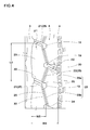
- FIG. 4 shows a partial enlarged view of the middle portion 6.
- the middle portion 6 is provided with a circumferentially and continuously extending middle sub groove 20, a plurality of outer middle lateral grooves 21, and a plurality of inner middle lateral grooves 22.
- the middle sub groove 20 is configured to a zigzag form that includes a first inclined element 20a and a second inclined element 20b inclined an opposite direction with respect to the first inclined element 20a. Furthermore, the middle sub groove 20 includes width-expanded portions 19 between the first inclined element 20a and the second inclined element 20b. The width-expanded portions 19 have locally wide axial widths in order to improve wet performance of the tire.
- the second inclined element 20b preferably has a circumferential length longer than that of the first inclined element 20a. Thus, since resonance of noise generated from the respective first and second inclined elements 20a and 20b may be prevented, noise performance of the tire may be improved.
- Each outer middle lateral groove 21 extends from the middle sub groove 20 to the shoulder main groove 3 with an inclination with respect to the axial direction of the tire.
- the outer middle lateral groove 21 has an axially inner end communicated with the width-expanded portion 19 of the middle sub groove 20, whereby the water in the width-expanded portion 19 effectively dispersed through the outer middle lateral groove 21 and the shoulder main groove 3 so that wet performance may be further improved.
- the axially outer middle lateral groove 21 has a constant groove width.
- the outer middle lateral groove 21 preferably has an angle ⁇ 1 in a range of not less than 20 degrees, more preferably not less than 24 degrees, but preferably not more than 30 degrees, more preferably not more than 26 degrees with respect to the radial direction of the tire.
- Each inner middle lateral groove 22 extends from the middle sub groove 20 toward the center main groove 4.
- the inner middle lateral groove 22 has an axially outer end communicated with the width-expanded portion 19 of the middle sub groove 20.
- the inner middle lateral groove 22 has an axially inner end that terminates within the middle portion 6 without reaching the center main groove 4. Accordingly, noise performance of the tire may be improved, since resonance noise generated in the center main groove 4 may not be dispersed through the inner middle lateral grooves 22.
- each inner middle lateral groove 22 is inclined at an angle with respect to the axial direction of the tire with the same direction to the outer middle lateral grooves 21.
- the inner middle lateral grooves 22 have constant groove width.
- each inner middle lateral groove 22 preferably has an angle ⁇ 2 in a range of not less than 20 degrees, more preferably not less than 24 degrees, but preferably not more than 30 degrees, more preferably not more than 26 degrees with respect to the radial direction of the tire.
- the number of outer middle lateral grooves 21 is in a range of from 40 to 50, more preferably from 42 to 48.
- the number of inner middle lateral grooves 22 is in a range of from 40 to 50, more preferably from 42 to 48.
- the respective middle portions 6 include a plurality of axially outer middle blocks 23 each of which is divided among the shoulder main groove 3, adjacent outer middle lateral grooves 21 and 21, and the middle sub groove 20.
- each outer middle block 23 preferably has its circumferential length L2 in a range of not less than 0.50 times, more preferably not less than 0.55 times, but preferably not more than 0.80 times, more preferably not more than 0.75 times, in relation to the maximum circumferential ground contact length Lc of the tread portion 2 as shown in FIG. 2 .
- the maximum circumferential ground contact length Lc is measured under the standard loaded condition defined above.
- the outer middle block 23 preferably has its axial width W5 in a range of not less than 0.10 times, more preferably not less than 0.13 times, but preferably not more than 0.20 times, more preferably not more than 0.17 times in relation to the tread width TW (shown in FIG. 1 ).
- Each of the outer middle lateral grooves 21 and the inner middle lateral grooves 22 include a shallow bottom part 25 having a depth smaller than that of the shoulder main grooves 3 and the center main groove 4 so that the middle portion 6 may have high rigidity. Thus, deformation of the middle portion 6 during traveling may be reduced, thereby decreasing rolling resistance of the tire.
- FIG. 5 shows a perspective view of the outer middle lateral groove 21.
- the shallow bottom part 25 preferably has a depth D3 in a range of not less than 0.10 times, more preferably not less than 0.13 times, but preferably not more than 0.20 times, more preferably not more than 0.17 times, in order further improve rolling resistance while maintaining wet performance of the tire.
- the shallow bottom part 25 is disposed a groove bottom sipe 30 that straightly extends along a longitudinal direction of each lateral groove 21 and 22, for example.
- a groove bottom sipe 30 may help to improve drainage performance of the tire.
- the groove bottom sipe 30 is provided in a center region in relation to a groove width direction of the shallow bottom part 25.
- the groove bottom sipe 30 preferably has a width W6 in a range of from not less than 0.3mm, more preferably not less than 0.5mm, but preferably not more than 1.0mm, more preferably not more than 0.8mm.
- FIG. 6 shows a perspective view of the outer middle lateral groove 21 including a cross section B-B in FIG. 5 .
- the groove bottom sipe 30 has a bottom 31 that includes different depths along the sipe longitudinal direction.
- the groove bottom sipe 30 includes a first portion 32 and a second portion 33 having a depth smaller than that of the first portion 32.
- FIG. 7 shows a cross sectional view taken along a line B-B in FIG. 5 .
- the first portion 32 of the groove bottom sipe 30 has a depth D4 from the top surface 6s of the middle portion 6 to its bottom.
- the depth D4 of the first portion 32 of the groove bottom sipe 30 is preferably set in a range of from 0.85 to 1.0 times in relation to the depth D2 (shown in FIG. 3 ) of the center main groove 4.
- the middle portion 6 tends to have low rigidity, thereby increasing rolling resistance of the tire.
- the depth D4 of the first portion 32 is less than 0.85 times in relation to the depth D2 of the center main groove 4, drainage performance of the outer middle lateral groove 21 tends to deteriorate.
- the depth D4 of the first portion 32 is set in a range of not more than 0.98 times, more preferably not more than 0.95 times, but preferably not less than 0.88 times, more preferably not less than 0.90 times, in relation to the depth D2 of the center main groove 4.
- the second portion 33 of the groove bottom sipe 30 has a depth D6 from the top surface of the shallow bottom part 25 to its bottom.
- the depth D6 of the second portion 33 is preferably set in a range of from 0.30 to 0.70 times in relation to a depth D5 from the top surface of the shallow bottom part 25 to the bottom of the first portion 32.
- such a second portion 33 may help to reduce the amount of deformation on the outer middle lateral groove, thereby reducing rolling resistance of the tire.
- the depth D6 of the second portion 33 is more than 0.70 times in relation to the depth D5 of the first portion 32 above, the relatively large deformation during traveling may be caused around the outer middle lateral groove 21.
- the depth D6 of the second portion 33 is less than 0.30 times in relation to the depth D5 of the first portion 32 above, drainage performance of the outer middle lateral groove 21 tends to deteriorate.
- the depth D6 of the second portion 33 is set in a range of not more than 0.60 times, more preferably not more than 0.55 times, but preferably not less than 0.40 times, more preferably not less than 0.35 times, in relation to the depth D5 of the first portion 32.
- the first portion 21 and second portion 33 are alternately arranged in a longitudinal direction of the groove bottom sipe 30.
- the groove bottom sipe 30 may have the bottom enhanced in well balanced along the longitudinal direction of the sipe so that deformation on the middle portion 6 during traveling is reduced.
- the respective longitudinal lengths L4 and L5 of the first portion 32 and the second portion 33 are set in a range of not less than 0.20 times, more preferably not less than 0.25 times, but preferably not more than 0.40 times, more preferably not more than 0.35 times, in relation to a longitudinal length L3 (shown in FIG. 1 ) of the groove bottom sipe 30.
- the shallow bottom part 25 and the groove bottom sipe 30 may be disposed on the middle sub groove 20.
- wet performance as well as low rolling resistance may further be improved.
- the groove bottom sipe 30 on the middle sub groove 20 preferably has one end that is connected with the groove bottom sipe 30 extending on the outer or inner middle lateral groove 21 or 22, and the other end that terminates within the middle sub groove 20 without connecting any other sipe.
- Heavy duty pneumatic tires shown in FIG. 1 and Table 1 were made and tested with respect to rolling resistance, wet performance and anti stone-biting performance.
- Major common specifics of tires and test methods are as follows.
- Rolling resistance of each test tire was measured under the following condition, using a tester.
- the test results were evaluated as the reciprocal of the rolling resistance and were indicated using an index based on Ref.1 being 100 in Table 1. The larger the index, the better the rolling resistance is.
- test tires were installed in a 2-D truck with a half load to its carrying capacity 10 tons, as its whole wheels. Then, a test driver suddenly started the truck using the second gear position by engaging its clutch at the timing of a 1,500rpm engine speed on a wet asphalt road with a puddle 5mm deep, and measured the time for traveling to 10m distance. The test results were evaluated as the reciprocal of the time and were indicated using an index based on Ref.1 being 100 in Table 1. The larger the index, the better the wet performance is.
- test tires were installed in the truck above with a full load to its carrying capacity 10 tons, as its whole wheels. After 100m running on a gravel road, the whole weight of stones bitten in the shoulder and center main grooves was measured. The test results were evaluated as the reciprocal of the whole weight of the stones and were indicated using an index based on Ref.1 being 100 in Table 1. The larger the index, the better the anti stone-biting performance is.
Abstract
Description
- The present invention relates to a heavy duty pneumatic tire that offers low rolling resistance while maintaining wet performance as well as anti-stone-biting performance.
- A pneumatic tire having low rolling resistance is recently proposed. Japanese Unexamined Patent Application Publication No.
2006-341769 - However, such a pneumatic tire tends to have disadvantage of low wet performance. Furthermore, such a pneumatic tire tends to bite a stone in its grooves and hold it in long term.
- The present invention has been worked out in light of the circumstances described above, and has a main object of providing a heavy duty pneumatic tire that offers low rolling resistance while maintaining wet performance as well as anti-stone-biting performance.
- According to one aspect of the present invention, a heavy duty pneumatic tire includes a tread portion provided with a plurality of circumferentially and continuously extending main grooves that include a pair of shoulder main grooves disposed axially outermost side, and at least one center main groove disposed between the shoulder main grooves, and the tread portion including a pair of middle portions each of which is between the shoulder main groove and the center main groove. Each middle portion is provided with a circumferentially and continuously extending middle sub groove, a plurality of axially outer middle lateral grooves extending from the middle sub groove to the shoulder main groove, and a plurality of axially inner middle lateral grooves extending from the middle sub groove toward the center main groove. The outer middle lateral grooves and the inner middle lateral grooves are inclined at angle with respect to an axial direction of the tire with the same direction. The respective number of outer middle lateral grooves and the inner middle lateral grooves are in a range of from 40 to 50 in each middle portion. Each of the outer middle lateral grooves and the inner middle lateral grooves includes a shallow bottom part having a depth smaller than that of the shoulder main grooves and the center main groove. The shallow bottom part is provided with a groove bottom sipe extending along a longitudinal direction of each lateral groove, and the groove bottom sipe includes a first portion having a depth from a top surface of the middle portion to its bottom in a range of from 0.85 to 1.0 times in relation to a depth of the center main groove, and a second portion having a depth from a top surface of the shallow bottom part to its bottom in a range of from 0.30 to 0.70 times in relation to a depth from a top surface of the shallow bottom part to a bottom of the first portion.
- In the aspect of the present invention, the middle sub groove may be configured to a zigzag form that includes a first inclined element and a second inclined element inclined an opposite direction with respect to the first inclined element and having a circumferential length longer than that of the first inclined element.
- In the aspect of the present invention, the middle portion may include a plurality of outer middle blocks between the outer middle lateral grooves, and each outer middle block has a circumferential length in a range of from 0.50 to 0.80 times in relation to a maximum circumferential ground contact length of the tread portion under a standard loaded condition in which the tire is mounted on a standard wheel rim with a standard pressure and is loaded with a standard tire load at a camber angle of zero.
- In the aspect of the present invention, the first portion of the groove bottom sipe may have a longitudinal length in a range of from 0.20 to 0.40 times the whole length of the groove bottom sipe.
- In the aspect of the present invention, the groove bottom sipe may include the first portion and second portion alternately arranged in a circumferential direction of the tire.
-
-
FIG. 1 is a development view of a tread portion of a heavy duty pneumatic tire showing an embodiment of the present invention; -
FIG. 2 is a ground contact patch of the tire shown inFIG. 1 ; -
FIG. 3 is a cross sectional view of the tread portion taken along a line A-A inFIG. 1 ; -
FIG. 4 is a partial enlarged view of a middle portion of the tread portion shown inFIG. 1 ; -
FIG. 5 is a perspective view of an outer middle lateral groove shown inFIG. 4 ; -
FIG. 6 is a perspective view of the outer middle lateral groove including a cross section B-B inFIG. 5 ; and -
FIG. 7 is a cross sectional view taken along a line B-B inFIG. 5 . - An embodiment of the present invention will be explained below with reference to the accompanying drawings.
- As shown in
FIG. 1 , a heavy dutypneumatic tire 1 for trucks or busses in accordance with the present invention comprises atread portion 2 provided with a plurality of circumferentially and continuously extending main grooves that include a pair of shouldermain grooves main grooves main grooves tread portion 2 is separated into a plurality of land portions that include acentral portion 5 between the centermain grooves middle portions main groove 3 and shouldermain groove 4. - As shown in
FIG. 2 , thetread portion 2 includes a pair of tread edges Te and Te. The tread edge Te is defined as an axially outer edge in a ground contact patch of the tread portion under a standard loaded condition in which thetire 1 is mounted on a standard wheel rim with a standard pressure and is loaded with a standard tire load at a camber angle of set to zero. A tread width TW shown inFIG. 1 is an axial distance between the tread edges Te and Te under a standard unloaded condition in which thetire 1 is mounted on the standard wheel rim with the standard pressure and is loaded with no tire load. In this application including specification and claims, various dimensions, positions and the like of the tire refer to those under the standard unloaded condition of the tire unless otherwise noted. - Here, the standard wheel rim is a wheel rim officially approved or recommended for the tire by standards organizations, i.e. JATMA, TRA, ETRTO, and the like which are effective in the area where the tire is manufactured, sold or used. For example, the standard wheel rim is the "standard rim" specified in JATMA, the "Measuring Rim" in ETRTO, and the "Design Rim" in TRA or the like.
- The standard pressure and the standard tire load are the maximum air pressure and the maximum tire load for the tire specified by the same organization in the Air-pressure/Maximum-load Table or similar list.
- The standard pressure is the "maximum air pressure" in JATMA, the "Inflation Pressure" in ETRTO, and the maximum pressure given in the "Tire Load Limits at Various Cold Inflation Pressures" table in TRA or the like.
- The standard tire load is the "maximum load capacity" in JATMA, the "Load Capacity" in ETRTO, and the maximum value given in the above-mentioned table in TRA or the like.
- Preferably, the
tread portion 2 has a land ratio in a range of from 70% to 80%, more preferably in a range of from 75 % to 80% in order to offer low rolling resistance of the tire due to its high tread pattern rigidity. Here, the land ratio of thetread portion 2 is a ratio of a net ground contact area to a gross total ground contact area on the tread portion. - In order to effectively drain the water from under the
tread portion 2, each of the shouldermain grooves 3 and centermain grooves 4 may be configured to a zigzag or straight form that continuously extends in the circumferential direction of the tire. - In order to further improve wet performance and steering stability of the tire, the shoulder
main grooves 3 preferably have its groove widths W1 in a range of 3.0% to 4.0% the tread width TW, and the centermain grooves 4 preferably have its groove widths W2 in a range of 2.0% to 3.0% the tread width TW. -
FIG. 3 shows a cross sectional view of thetread portion 2 taken along the line A-A ofFIG. 1 . Referring toFIG. 3 , the shouldermain grooves 3 and centermain grooves 4 preferably have the respective groove depths D1 and D2 in a range of from 12 to 20 mm. - Referring back to
FIG.1 , thecentral portion 5 is provided with a plurality of centerlateral grooves 10 that have both ends communicated with centermain grooves lateral groove 10 has a constant groove width and is inclined at an angle with respect to the axial direction of the tire. Thecenter portion 5 is divided into a plurality ofcenter blocks 11. - Each
center block 11 has a circumferentially long rectangular top surface that comes into contact with the road. The top surface of thecenter block 11 preferably has the maximum axial width W3 in a range of not less than 0.10 times, more preferably not less than 0.13 times, but preferably not more than 0.20 times, more preferably not more than 0.17 times the tread width TW. Since thecenter blocks 5 enhances pattern rigidity in thecentral portion 5, low rolling resistance may be provided. - In order to offer superior wet performance and low rolling resistance of the tire, the top surface of the
center block 11 preferably has its circumferential length L1 in a range of not less than 0.50 times, more preferably not less than 0.60 times, but preferably not more than 0.80 times, more preferably not more than 0.70 times in relation to a maximum circumferentially ground contact length Lc (shown inFIG. 2 ) of thetread portion 2, under the standard loaded condition. -
FIG. 4 shows a partial enlarged view of themiddle portion 6. Referring toFIG. 4 , themiddle portion 6 is provided with a circumferentially and continuously extendingmiddle sub groove 20, a plurality of outer middlelateral grooves 21, and a plurality of inner middlelateral grooves 22. - The
middle sub groove 20 is configured to a zigzag form that includes a firstinclined element 20a and a secondinclined element 20b inclined an opposite direction with respect to the firstinclined element 20a. Furthermore, themiddle sub groove 20 includes width-expandedportions 19 between the firstinclined element 20a and the secondinclined element 20b. The width-expandedportions 19 have locally wide axial widths in order to improve wet performance of the tire. - The second
inclined element 20b preferably has a circumferential length longer than that of the firstinclined element 20a. Thus, since resonance of noise generated from the respective first and secondinclined elements - Each outer middle
lateral groove 21 extends from themiddle sub groove 20 to the shouldermain groove 3 with an inclination with respect to the axial direction of the tire. The outer middlelateral groove 21 has an axially inner end communicated with the width-expandedportion 19 of themiddle sub groove 20, whereby the water in the width-expandedportion 19 effectively dispersed through the outer middlelateral groove 21 and the shouldermain groove 3 so that wet performance may be further improved. In this embodiment, the axially outer middlelateral groove 21 has a constant groove width. - In order to further improve drainage performance as well as cornering performance on wet roads, the outer middle
lateral groove 21 preferably has an angle θ1 in a range of not less than 20 degrees, more preferably not less than 24 degrees, but preferably not more than 30 degrees, more preferably not more than 26 degrees with respect to the radial direction of the tire. - Each inner middle
lateral groove 22 extends from themiddle sub groove 20 toward the centermain groove 4. The inner middlelateral groove 22 has an axially outer end communicated with the width-expandedportion 19 of themiddle sub groove 20. - The inner middle
lateral groove 22 has an axially inner end that terminates within themiddle portion 6 without reaching the centermain groove 4. Accordingly, noise performance of the tire may be improved, since resonance noise generated in the centermain groove 4 may not be dispersed through the inner middlelateral grooves 22. - The inner middle
lateral grooves 22 are inclined at an angle with respect to the axial direction of the tire with the same direction to the outer middlelateral grooves 21. In this embodiment, the inner middlelateral grooves 22 have constant groove width. In order to further improve drainage performance as well as cornering performance on wet roads, each inner middlelateral groove 22 preferably has an angle θ2 in a range of not less than 20 degrees, more preferably not less than 24 degrees, but preferably not more than 30 degrees, more preferably not more than 26 degrees with respect to the radial direction of the tire. - In the respective
middle portions 6, the number of outer middlelateral grooves 21 is in a range of from 40 to 50, more preferably from 42 to 48. Similarly, in the respectivemiddle portions 6, the number of inner middlelateral grooves 22 is in a range of from 40 to 50, more preferably from 42 to 48. Such a tire having few middle lateral grooves as compared to the conventional one may help to improve rigidity of the tread pattern and reduce biting a stone in its inner and outer middle lateral grooves. - The respective
middle portions 6 include a plurality of axially outer middle blocks 23 each of which is divided among the shouldermain groove 3, adjacent outer middlelateral grooves middle sub groove 20. - In order to further improve wet performance as well as low rolling resistance of the tire, each outer
middle block 23 preferably has its circumferential length L2 in a range of not less than 0.50 times, more preferably not less than 0.55 times, but preferably not more than 0.80 times, more preferably not more than 0.75 times, in relation to the maximum circumferential ground contact length Lc of thetread portion 2 as shown inFIG. 2 . The maximum circumferential ground contact length Lc is measured under the standard loaded condition defined above. - In the same point of view, the outer
middle block 23 preferably has its axial width W5 in a range of not less than 0.10 times, more preferably not less than 0.13 times, but preferably not more than 0.20 times, more preferably not more than 0.17 times in relation to the tread width TW (shown inFIG. 1 ). - Each of the outer middle
lateral grooves 21 and the inner middlelateral grooves 22 include a shallowbottom part 25 having a depth smaller than that of the shouldermain grooves 3 and the centermain groove 4 so that themiddle portion 6 may have high rigidity. Thus, deformation of themiddle portion 6 during traveling may be reduced, thereby decreasing rolling resistance of the tire. -
FIG. 5 shows a perspective view of the outer middlelateral groove 21. Referring toFIG. 5 , the shallowbottom part 25 preferably has a depth D3 in a range of not less than 0.10 times, more preferably not less than 0.13 times, but preferably not more than 0.20 times, more preferably not more than 0.17 times, in order further improve rolling resistance while maintaining wet performance of the tire. - The shallow
bottom part 25 is disposed agroove bottom sipe 30 that straightly extends along a longitudinal direction of eachlateral groove groove bottom sipe 30 may help to improve drainage performance of the tire. Preferably, thegroove bottom sipe 30 is provided in a center region in relation to a groove width direction of the shallowbottom part 25. - In order to further improve drainage performance and rolling resistance of the tire, the
groove bottom sipe 30 preferably has a width W6 in a range of from not less than 0.3mm, more preferably not less than 0.5mm, but preferably not more than 1.0mm, more preferably not more than 0.8mm. -
FIG. 6 shows a perspective view of the outer middlelateral groove 21 including a cross section B-B inFIG. 5 . Referring toFIG.6 , thegroove bottom sipe 30 has a bottom 31 that includes different depths along the sipe longitudinal direction. In this embodiment, thegroove bottom sipe 30 includes afirst portion 32 and asecond portion 33 having a depth smaller than that of thefirst portion 32. -
FIG. 7 shows a cross sectional view taken along a line B-B inFIG. 5 . Referring toFIG. 7 , thefirst portion 32 of thegroove bottom sipe 30 has a depth D4 from thetop surface 6s of themiddle portion 6 to its bottom. In order to improve drainage performance of the outer middlelateral grooves 21, the depth D4 of thefirst portion 32 of thegroove bottom sipe 30 is preferably set in a range of from 0.85 to 1.0 times in relation to the depth D2 (shown inFIG. 3 ) of the centermain groove 4. - In case that the depth D4 of the
first portion 32 is more than 1.0 times in relation to the depth D2 of the centermain groove 4, themiddle portion 6 tends to have low rigidity, thereby increasing rolling resistance of the tire. In case that the depth D4 of thefirst portion 32 is less than 0.85 times in relation to the depth D2 of the centermain groove 4, drainage performance of the outer middlelateral groove 21 tends to deteriorate. Preferably, the depth D4 of thefirst portion 32 is set in a range of not more than 0.98 times, more preferably not more than 0.95 times, but preferably not less than 0.88 times, more preferably not less than 0.90 times, in relation to the depth D2 of the centermain groove 4. - The
second portion 33 of thegroove bottom sipe 30 has a depth D6 from the top surface of the shallowbottom part 25 to its bottom. In order to improve drainage performance of the outer middlelateral grooves 21 while offering suitable rigidity in themiddle portion 6 for improving anti-stone-biting performance, the depth D6 of thesecond portion 33 is preferably set in a range of from 0.30 to 0.70 times in relation to a depth D5 from the top surface of the shallowbottom part 25 to the bottom of thefirst portion 32. Furthermore, such asecond portion 33 may help to reduce the amount of deformation on the outer middle lateral groove, thereby reducing rolling resistance of the tire. - In case that the depth D6 of the
second portion 33 is more than 0.70 times in relation to the depth D5 of thefirst portion 32 above, the relatively large deformation during traveling may be caused around the outer middlelateral groove 21. In case that the depth D6 of thesecond portion 33 is less than 0.30 times in relation to the depth D5 of thefirst portion 32 above, drainage performance of the outer middlelateral groove 21 tends to deteriorate. Preferably, the depth D6 of thesecond portion 33 is set in a range of not more than 0.60 times, more preferably not more than 0.55 times, but preferably not less than 0.40 times, more preferably not less than 0.35 times, in relation to the depth D5 of thefirst portion 32. - Preferably, the
first portion 21 andsecond portion 33 are alternately arranged in a longitudinal direction of thegroove bottom sipe 30. Thus, thegroove bottom sipe 30 may have the bottom enhanced in well balanced along the longitudinal direction of the sipe so that deformation on themiddle portion 6 during traveling is reduced. - Preferably, the respective longitudinal lengths L4 and L5 of the
first portion 32 and thesecond portion 33 are set in a range of not less than 0.20 times, more preferably not less than 0.25 times, but preferably not more than 0.40 times, more preferably not more than 0.35 times, in relation to a longitudinal length L3 (shown inFIG. 1 ) of thegroove bottom sipe 30. - As shown in
FIG. 4 , the shallowbottom part 25 and thegroove bottom sipe 30 may be disposed on themiddle sub groove 20. Thus, wet performance as well as low rolling resistance may further be improved. - In order to maintain steering stability of the tire by preventing reduction in rigidity of the
middle portion 6, thegroove bottom sipe 30 on themiddle sub groove 20 preferably has one end that is connected with thegroove bottom sipe 30 extending on the outer or inner middlelateral groove middle sub groove 20 without connecting any other sipe. - The present invention is more specifically described and explained by means of the following Examples and References. It is to be understood that the present invention is not limited to these Examples and embodiments described above.
- Heavy duty pneumatic tires shown in
FIG. 1 and Table 1 were made and tested with respect to rolling resistance, wet performance and anti stone-biting performance. Major common specifics of tires and test methods are as follows. - Details of test tires:
- Size: 275/80R22.5
- Rim: 22.5x7.5
- Internal pressure: 900kPa
- Tread width TW: 248mm
- Shoulder main groove width W1: 10mm
- Shoulder main groove depth D1: 16mm
- Center main groove width W2: 6mm
- Center main groove depth D2: 16mm
- Rolling resistance of each test tire was measured under the following condition, using a tester. The test results were evaluated as the reciprocal of the rolling resistance and were indicated using an index based on Ref.1 being 100 in Table 1. The larger the index, the better the rolling resistance is.
- Tire load: 33.83kN
- Speed: 80km/h
- The test tires were installed in a 2-D truck with a half load to its
carrying capacity 10 tons, as its whole wheels. Then, a test driver suddenly started the truck using the second gear position by engaging its clutch at the timing of a 1,500rpm engine speed on a wet asphalt road with a puddle 5mm deep, and measured the time for traveling to 10m distance. The test results were evaluated as the reciprocal of the time and were indicated using an index based on Ref.1 being 100 in Table 1. The larger the index, the better the wet performance is. - The test tires were installed in the truck above with a full load to its
carrying capacity 10 tons, as its whole wheels. After 100m running on a gravel road, the whole weight of stones bitten in the shoulder and center main grooves was measured. The test results were evaluated as the reciprocal of the whole weight of the stones and were indicated using an index based on Ref.1 being 100 in Table 1. The larger the index, the better the anti stone-biting performance is. - Test results are shown in Table 1. From the test results, it was confirmed that Example tires in accordance with the present invention can be effectively improved rolling performance while maintaining wet road performance and anti stone-biting performance.
Table 1-1 Ref. 1 Ref. 2 Ex. 1 Ex. 2 Ex. 3 Ex. 4 Ex. 5 Ex. 6 Ref. 3 Ex. 7 Ex. 8 Ref. 4 Land ratio (%) 78 78 78 65 70 75 80 85 78 78 78 78 Number of outer middle lateral groove in each middle portion 45 45 45 45 45 45 45 45 45 45 45 45 Number of inner middle lateral groove in each middle portion 45 45 45 45 45 45 45 45 45 45 45 45 Outer middle block length L2/Lc 0.65 0.65 0.65 0.65 0.65 0.65 0.65 0.65 0.65 0.65 0.65 0.65 Outer middle block width W5/TW 0.15 0.15 0.15 0.15 0.15 0.15 0.15 0.15 0.15 0.15 0.15 0.15 Shallow bottom part Absence Presence Presence Presence Presence Presence Presence Presence Presence Presence Presence Presence Groove bottom sipe Absence Presence Presence Presence Presence Presence Presence Presence Presence Presence Presence Presence Ratio L4/L3 - - 0.25 0.25 0.25 0.25 0.25 0.25 0.25 0.25 0.25 0.25 Ratio D4/D2 - - 0.93 0.93 0.93 0.93 0.93 0.93 0.93 0.93 0.93 0.93 Ratio D6/D5 - - 0.65 0.65 0.65 0.65 0.65 0.65 0.5 0.6 0.7 0.8 Rolling resistance (Index) 100 100 110 105 108 110 110 110 110 110 110 110 Wet performance (Index) 100 100 110 110 110 110 110 105 105 108 108 108 Anti stone-biting performance (Index) 100 105 110 110 110 110 110 110 110 110 110 105 Table 1-2 Ex. 9 Ex. 10 Ex. 11 Ex. 12 Ex. 13 Ex. 14 Ex. 15 Ex. 16 Ex. 17 Ex. 18 Ex. 19 Ex. 20 Land ratio (%) 78 78 78 78 78 78 78 78 78 78 78 78 Number of outer middle lateral groove in each middle portion 38 40 42 48 50 52 45 45 45 45 45 45 Number of inner middle lateral groove in each middle portion 38 40 42 48 50 52 45 45 45 45 45 45 Outer middle block length L2/Lc 0.65 0.65 0.65 0.65 0.65 0.65 0.45 0.5 0.55 0. 75 0.8 0.85 Outer middle block width W5/TW 0.15 0.15 0.15 0.15 0.15 0.15 0.15 0.15 0.15 0.15 0.15 0.15 Shallow bottom part Presence Presence Presence Presence Presence Presence Presence Presence Presence Pres. Pres. Pres. Groove bottom sipe Presence Presence Presence Presence Presence Presence Presence Presence Presence Presence Presence Presence Ratio L4/L3 0.25 0.25 0.25 0.25 0.25 0.25 0.25 0.25 0.25 0.25 0.25 0.25 Ratio D4/D2 0.93 0.93 0.93 0.93 0.93 0.93 0.93 0.93 0.93 0.93 0.93 0.93 Ratio D6/D5 0.65 0.65 0.65 0.65 0.65 0.65 0.65 0.65 0.65 0.65 0.65 0.65 Rolling resistance (Index) 110 110 110 110 108 105 105 108 110 110 110 110 Wet performance (Index) 105 108 110 110 110 110 110 110 110 110 108 105 Anti stone-biting performance (Index) 110 110 110 110 110 110 110 110 110 110 110 110 Table 1-3 Ex. 21 Ex. 22 Ex. 23 Ex. 24 Ex. 25 Ex. 26 Ex. 27 Ref. 5 Ex. 28 Ex. 29 Land ratio (%) 78 78 78 78 78 78 78 78 78 78 Number of outer middle lateral groove in each middle portion 45 45 45 45 45 45 45 45 45 45 Number of inner middle lateral groove in each middle portion 45 45 45 45 45 45 45 45 45 45 Outer middle block length L2/Lc 0.65 0.65 0.65 0.65 0.65 0.65 0.65 0.65 0.65 0.65 Outer middle block width W5/TW 0.1 0.13 0.17 0.2 0.15 0.15 0.15 0.15 0.15 0.15 Shallow bottom part Presence Presence Presence Presence Presence Presence Presence Presence Presence Presence Groove bottom sipe Presence Presence Presence Presence Presence Presence Presence Presence Presence Presence Ratio L4/L3 0.25 0.25 0.25 0.25 0.2 0.4 0.45 0.25 0.25 0.25 Ratio D4/D2 0.93 0.93 0.93 0.93 0.93 0.93 0.93 0.6 0.85 1 Ratio D6/D5 0.65 0.65 0.65 0.65 0.65 0.65 0.65 0.65 0.65 0.65 Rolling resistance (Index) 108 110 110 110 110 110 110 110 110 108 Wet performance (Index) 110 110 110 108 110 110 110 105 108 110 Anti stone-biting performance (Index) 110 110 110 110 107 107 105 110 110 110
Claims (5)
- A heavy duty pneumatic tire comprising
a tread portion provided with a plurality of circumferentially and continuously extending main grooves that include a pair of shoulder main grooves disposed axially outermost side, and at least one center main groove disposed between the shoulder main grooves, the tread portion including a pair of middle portions each of which is between the shoulder main groove and the center main groove,
each middle portion provided with a circumferentially and continuously extending middle sub groove, a plurality of axially outer middle lateral grooves extending from the middle sub groove to the shoulder main groove, and a plurality of axially inner middle lateral grooves extending from the middle sub groove toward the center main groove,
the outer middle lateral grooves and the inner middle lateral grooves inclined at angle with respect to an axial direction of the tire with the same direction, the respective number of outer middle lateral grooves and the inner middle lateral grooves being in a range of from 40 to 50 in each middle portion, each of the outer middle lateral grooves and the inner middle lateral grooves including a shallow bottom part having a depth smaller than that of the shoulder main grooves and the center main groove,
the shallow bottom part provided with a groove bottom sipe extending along a longitudinal direction of each lateral groove, and
the groove bottom sipe including a first portion and a second portion, the first portion having a depth from a top surface of the middle portion to its bottom in a range of from 0.85 to 1.0 times in relation to a depth of the center main groove, the second portion having a depth from a top surface of the shallow bottom part to its bottom in a range of from 0.30 to 0.70 times in relation to a depth from a top surface of the shallow bottom part to a bottom of the first portion. - The tire according to claim 1,
wherein the middle sub groove is configured to a zigzag form that includes a first inclined element and a second inclined element inclined an opposite direction with respect to the first inclined element and having a circumferential length longer than that of the first inclined element. - The tire according to claim 1 or 2,
wherein the middle portion includes a plurality of outer middle blocks between the outer middle lateral grooves, and
each outer middle block has a circumferential length in a range of from 0.50 to 0.80 times in relation to a maximum circumferential ground contact length of the tread portion under a standard loaded condition in which the tire is mounted on a standard wheel rim with a standard pressure and is loaded with a standard tire load at a camber angle of zero. - The tire according to any one of the claims 1 to 3,
wherein the first portion of the groove bottom sipe has a longitudinal length in a range of from 0.20 to 0.40 times the whole length of the groove bottom sipe. - The tire according to any one of the claims 1 to 4,
wherein the groove bottom sipe includes the first portion and second portion alternately arranged in a circumferential direction of the tire.
Applications Claiming Priority (1)
| Application Number | Priority Date | Filing Date | Title |
|---|---|---|---|
| JP2013026982A JP5698776B2 (en) | 2013-02-14 | 2013-02-14 | Heavy duty pneumatic tire |
Publications (3)
| Publication Number | Publication Date |
|---|---|
| EP2767413A2 true EP2767413A2 (en) | 2014-08-20 |
| EP2767413A3 EP2767413A3 (en) | 2014-09-03 |
| EP2767413B1 EP2767413B1 (en) | 2016-07-20 |
Family
ID=50030135
Family Applications (1)
| Application Number | Title | Priority Date | Filing Date |
|---|---|---|---|
| EP14153593.0A Active EP2767413B1 (en) | 2013-02-14 | 2014-02-03 | Heavy duty pneumatic tire |
Country Status (4)
| Country | Link |
|---|---|
| US (1) | US9132702B2 (en) |
| EP (1) | EP2767413B1 (en) |
| JP (1) | JP5698776B2 (en) |
| CN (1) | CN103991339B (en) |
Cited By (5)
| Publication number | Priority date | Publication date | Assignee | Title |
|---|---|---|---|---|
| US9930540B2 (en) | 2014-05-28 | 2018-03-27 | Corning Optical Communications LLC | Multiple application modules (MAMs) for monitoring signals in components in wireless distribution systems, including distributed antenna systems (DASs), and related systems and methods |
| US10194299B2 (en) | 2015-01-09 | 2019-01-29 | Corning Optical Communications LLC | Multiple application module or unit |
| US10314046B2 (en) | 2016-05-31 | 2019-06-04 | Corning Optical Communications LLC | Multiple application devices for providing services in wireless distribution systems (WDS), including distributed antenna systems (DAS), and related systems and methods |
| EP3498497A1 (en) * | 2017-12-13 | 2019-06-19 | Sumitomo Rubber Industries Ltd. | Tyre |
| US10424139B2 (en) | 2016-04-27 | 2019-09-24 | Corning Optical Communications LLC | Multiple application modules (MAM) and/or multiple application units (MAU) for providing services in wireless distribution systems (WDS), including distributed antenna systems (DAS), and related systems and methods |
Families Citing this family (9)
| Publication number | Priority date | Publication date | Assignee | Title |
|---|---|---|---|---|
| JP5937996B2 (en) * | 2013-04-03 | 2016-06-22 | 住友ゴム工業株式会社 | Heavy duty pneumatic tire |
| JP5718412B2 (en) * | 2013-07-02 | 2015-05-13 | 株式会社ブリヂストン | Pneumatic tire |
| US9636952B2 (en) * | 2014-01-08 | 2017-05-02 | Sumitomo Rubber Industries, Ltd. | Heavy duty pneumatic tire |
| USD773384S1 (en) * | 2014-04-18 | 2016-12-06 | Bridgestone Corporation | Tire tread |
| AU2017255556B2 (en) * | 2016-04-26 | 2020-03-05 | American Pacific Industries, Inc. | Tire with unique tread block and up sidewall designs |
| JP6493542B2 (en) * | 2016-07-19 | 2019-04-03 | 横浜ゴム株式会社 | Pneumatic tire |
| JP6724669B2 (en) * | 2016-09-08 | 2020-07-15 | 横浜ゴム株式会社 | Pneumatic tire |
| CN112996672B (en) * | 2018-11-16 | 2022-12-23 | 米其林集团总公司 | Heavy truck tire with shoulder rib sipe arrangement |
| JP7155984B2 (en) * | 2018-12-13 | 2022-10-19 | 住友ゴム工業株式会社 | motorcycle tire |
Citations (1)
| Publication number | Priority date | Publication date | Assignee | Title |
|---|---|---|---|---|
| JP2006341769A (en) | 2005-06-09 | 2006-12-21 | Sumitomo Rubber Ind Ltd | Pneumatic tire |
Family Cites Families (14)
| Publication number | Priority date | Publication date | Assignee | Title |
|---|---|---|---|---|
| FR2462281A1 (en) * | 1979-07-30 | 1981-02-13 | Michelin & Cie | TIRE FOR ROLLING OFF ROAD |
| JPH0326964Y2 (en) * | 1986-12-24 | 1991-06-11 | ||
| JPH03132404A (en) * | 1989-10-19 | 1991-06-05 | Bridgestone Corp | Pneumatic tire for heavy load |
| JP3136101B2 (en) * | 1996-09-19 | 2001-02-19 | 住友ゴム工業株式会社 | Pneumatic tire |
| JP4299745B2 (en) * | 2004-08-12 | 2009-07-22 | 住友ゴム工業株式会社 | Pneumatic tire |
| JP4359262B2 (en) * | 2005-05-13 | 2009-11-04 | 住友ゴム工業株式会社 | Pneumatic tire |
| JP4486592B2 (en) * | 2005-12-29 | 2010-06-23 | 住友ゴム工業株式会社 | Heavy duty tire |
| JP4963424B2 (en) * | 2007-02-21 | 2012-06-27 | 住友ゴム工業株式会社 | studless tire |
| JP2010058696A (en) * | 2008-09-04 | 2010-03-18 | Bridgestone Corp | Tire |
| JP5185983B2 (en) * | 2010-08-10 | 2013-04-17 | 住友ゴム工業株式会社 | Heavy duty pneumatic tire |
| JP5337196B2 (en) * | 2011-04-27 | 2013-11-06 | 住友ゴム工業株式会社 | Pneumatic tire |
| JP5778497B2 (en) * | 2011-06-21 | 2015-09-16 | 株式会社ブリヂストン | Heavy duty tire |
| CN103635333B (en) * | 2011-06-30 | 2017-06-09 | 米其林集团总公司 | Tire tread with the groove with inner void |
| JP5632823B2 (en) * | 2011-12-26 | 2014-11-26 | 住友ゴム工業株式会社 | Heavy duty pneumatic tire |
-
2013
- 2013-02-14 JP JP2013026982A patent/JP5698776B2/en active Active
-
2014
- 2014-01-09 US US14/150,794 patent/US9132702B2/en not_active Expired - Fee Related
- 2014-02-03 EP EP14153593.0A patent/EP2767413B1/en active Active
- 2014-02-08 CN CN201410045506.4A patent/CN103991339B/en active Active
Patent Citations (1)
| Publication number | Priority date | Publication date | Assignee | Title |
|---|---|---|---|---|
| JP2006341769A (en) | 2005-06-09 | 2006-12-21 | Sumitomo Rubber Ind Ltd | Pneumatic tire |
Cited By (12)
| Publication number | Priority date | Publication date | Assignee | Title |
|---|---|---|---|---|
| US9930540B2 (en) | 2014-05-28 | 2018-03-27 | Corning Optical Communications LLC | Multiple application modules (MAMs) for monitoring signals in components in wireless distribution systems, including distributed antenna systems (DASs), and related systems and methods |
| US10299143B2 (en) | 2014-05-28 | 2019-05-21 | Corning Optical Communications LLC | Multiple application modules (MAMs) for monitoring signals in components in wireless distribution systems, including distributed antenna systems (DASs), and related systems and methods |
| US10194299B2 (en) | 2015-01-09 | 2019-01-29 | Corning Optical Communications LLC | Multiple application module or unit |
| US10375554B2 (en) | 2015-01-09 | 2019-08-06 | Corning Optical Communications LLC | Multiple application module or unit |
| US11032687B2 (en) | 2015-01-09 | 2021-06-08 | Corning Optical Communications LLC | Multiple application module or unit |
| US11910290B2 (en) | 2015-01-09 | 2024-02-20 | Corning Optical Communications LLC | Multiple application module or unit |
| US10424139B2 (en) | 2016-04-27 | 2019-09-24 | Corning Optical Communications LLC | Multiple application modules (MAM) and/or multiple application units (MAU) for providing services in wireless distribution systems (WDS), including distributed antenna systems (DAS), and related systems and methods |
| US10885732B2 (en) | 2016-04-27 | 2021-01-05 | Corning Optical Communications LLC | Multiple application modules (MAM) and/or multiple application units (MAU) for providing services in wireless distribution systems (WDS), including distributed antenna systems (DAS), and related systems and methods |
| US10314046B2 (en) | 2016-05-31 | 2019-06-04 | Corning Optical Communications LLC | Multiple application devices for providing services in wireless distribution systems (WDS), including distributed antenna systems (DAS), and related systems and methods |
| US10887885B2 (en) | 2016-05-31 | 2021-01-05 | Corning Optical Communications LLC | Multiple application devices for providing services in wireless distribution systems (WDS), including distributed antenna systems (DAS), and related systems and methods |
| EP3498497A1 (en) * | 2017-12-13 | 2019-06-19 | Sumitomo Rubber Industries Ltd. | Tyre |
| US11148474B2 (en) | 2017-12-13 | 2021-10-19 | Sumitomo Rubber Industries, Ltd. | Tire |
Also Published As
| Publication number | Publication date |
|---|---|
| US9132702B2 (en) | 2015-09-15 |
| JP2014156165A (en) | 2014-08-28 |
| US20140224398A1 (en) | 2014-08-14 |
| JP5698776B2 (en) | 2015-04-08 |
| EP2767413B1 (en) | 2016-07-20 |
| EP2767413A3 (en) | 2014-09-03 |
| CN103991339B (en) | 2017-04-12 |
| CN103991339A (en) | 2014-08-20 |
Similar Documents
| Publication | Publication Date | Title |
|---|---|---|
| EP2767413B1 (en) | Heavy duty pneumatic tire | |
| EP2614966B1 (en) | Heavy duty pneumatic tire | |
| US9457621B2 (en) | Heavy duty pneumatic tire | |
| EP3205516B1 (en) | Pneumatic tire | |
| EP2639084B1 (en) | Pneumatic tire | |
| EP2769853B1 (en) | Pneumatic tire | |
| US10328751B2 (en) | Pneumatic tire | |
| EP2952362A1 (en) | Pneumatic tire | |
| EP2907674A1 (en) | Pneumatic tire | |
| US20130167996A1 (en) | Pneumatic tire | |
| EP2765010B1 (en) | Heavy duty pneumatic tire | |
| EP3153333A1 (en) | Pneumatic tire | |
| EP3156263B1 (en) | Pneumatic tire | |
| EP2213483A1 (en) | Pneumatic tire | |
| EP2777950B1 (en) | Pneumatic tire | |
| EP2786880A2 (en) | Heavy duty pneumatic tire | |
| EP3025878B1 (en) | Heavy duty pneumatic tire | |
| EP2127910A1 (en) | Pneumatic tire | |
| US9056530B2 (en) | Pneumatic tire | |
| US10232670B2 (en) | Pneumatic tire | |
| EP3321103B1 (en) | Heavy duty tire | |
| EP2821257A1 (en) | Pneumatic tire |
Legal Events
| Date | Code | Title | Description |
|---|---|---|---|
| PUAL | Search report despatched |
Free format text: ORIGINAL CODE: 0009013 |
|
| PUAI | Public reference made under article 153(3) epc to a published international application that has entered the european phase |
Free format text: ORIGINAL CODE: 0009012 |
|
| 17P | Request for examination filed |
Effective date: 20140203 |
|
| AK | Designated contracting states |
Kind code of ref document: A2 Designated state(s): AL AT BE BG CH CY CZ DE DK EE ES FI FR GB GR HR HU IE IS IT LI LT LU LV MC MK MT NL NO PL PT RO RS SE SI SK SM TR |
|
| AX | Request for extension of the european patent |
Extension state: BA ME |
|
| AK | Designated contracting states |
Kind code of ref document: A3 Designated state(s): AL AT BE BG CH CY CZ DE DK EE ES FI FR GB GR HR HU IE IS IT LI LT LU LV MC MK MT NL NO PL PT RO RS SE SI SK SM TR |
|
| AX | Request for extension of the european patent |
Extension state: BA ME |
|
| RIC1 | Information provided on ipc code assigned before grant |
Ipc: B60C 11/11 20060101AFI20140730BHEP Ipc: B60C 11/12 20060101ALI20140730BHEP Ipc: B60C 11/03 20060101ALI20140730BHEP |
|
| R17P | Request for examination filed (corrected) |
Effective date: 20150219 |
|
| RBV | Designated contracting states (corrected) |
Designated state(s): AL AT BE BG CH CY CZ DE DK EE ES FI FR GB GR HR HU IE IS IT LI LT LU LV MC MK MT NL NO PL PT RO RS SE SI SK SM TR |
|
| RIC1 | Information provided on ipc code assigned before grant |
Ipc: B60C 11/13 20060101ALI20160224BHEP Ipc: B60C 11/12 20060101ALI20160224BHEP Ipc: B60C 11/03 20060101ALI20160224BHEP Ipc: B60C 11/11 20060101AFI20160224BHEP |
|
| GRAP | Despatch of communication of intention to grant a patent |
Free format text: ORIGINAL CODE: EPIDOSNIGR1 |
|
| INTG | Intention to grant announced |
Effective date: 20160401 |
|
| GRAS | Grant fee paid |
Free format text: ORIGINAL CODE: EPIDOSNIGR3 |
|
| GRAA | (expected) grant |
Free format text: ORIGINAL CODE: 0009210 |
|
| AK | Designated contracting states |
Kind code of ref document: B1 Designated state(s): AL AT BE BG CH CY CZ DE DK EE ES FI FR GB GR HR HU IE IS IT LI LT LU LV MC MK MT NL NO PL PT RO RS SE SI SK SM TR |
|
| REG | Reference to a national code |
Ref country code: GB Ref legal event code: FG4D |
|
| REG | Reference to a national code |
Ref country code: CH Ref legal event code: EP |
|
| REG | Reference to a national code |
Ref country code: IE Ref legal event code: FG4D |
|
| REG | Reference to a national code |
Ref country code: AT Ref legal event code: REF Ref document number: 813740 Country of ref document: AT Kind code of ref document: T Effective date: 20160815 |
|
| REG | Reference to a national code |
Ref country code: DE Ref legal event code: R096 Ref document number: 602014002699 Country of ref document: DE |
|
| REG | Reference to a national code |
Ref country code: LT Ref legal event code: MG4D |
|
| REG | Reference to a national code |
Ref country code: NL Ref legal event code: MP Effective date: 20160720 |
|
| REG | Reference to a national code |
Ref country code: AT Ref legal event code: MK05 Ref document number: 813740 Country of ref document: AT Kind code of ref document: T Effective date: 20160720 |
|
| PG25 | Lapsed in a contracting state [announced via postgrant information from national office to epo] |
Ref country code: NO Free format text: LAPSE BECAUSE OF FAILURE TO SUBMIT A TRANSLATION OF THE DESCRIPTION OR TO PAY THE FEE WITHIN THE PRESCRIBED TIME-LIMIT Effective date: 20161020 Ref country code: LT Free format text: LAPSE BECAUSE OF FAILURE TO SUBMIT A TRANSLATION OF THE DESCRIPTION OR TO PAY THE FEE WITHIN THE PRESCRIBED TIME-LIMIT Effective date: 20160720 Ref country code: HR Free format text: LAPSE BECAUSE OF FAILURE TO SUBMIT A TRANSLATION OF THE DESCRIPTION OR TO PAY THE FEE WITHIN THE PRESCRIBED TIME-LIMIT Effective date: 20160720 Ref country code: RS Free format text: LAPSE BECAUSE OF FAILURE TO SUBMIT A TRANSLATION OF THE DESCRIPTION OR TO PAY THE FEE WITHIN THE PRESCRIBED TIME-LIMIT Effective date: 20160720 Ref country code: IT Free format text: LAPSE BECAUSE OF FAILURE TO SUBMIT A TRANSLATION OF THE DESCRIPTION OR TO PAY THE FEE WITHIN THE PRESCRIBED TIME-LIMIT Effective date: 20160720 Ref country code: FI Free format text: LAPSE BECAUSE OF FAILURE TO SUBMIT A TRANSLATION OF THE DESCRIPTION OR TO PAY THE FEE WITHIN THE PRESCRIBED TIME-LIMIT Effective date: 20160720 Ref country code: NL Free format text: LAPSE BECAUSE OF FAILURE TO SUBMIT A TRANSLATION OF THE DESCRIPTION OR TO PAY THE FEE WITHIN THE PRESCRIBED TIME-LIMIT Effective date: 20160720 Ref country code: IS Free format text: LAPSE BECAUSE OF FAILURE TO SUBMIT A TRANSLATION OF THE DESCRIPTION OR TO PAY THE FEE WITHIN THE PRESCRIBED TIME-LIMIT Effective date: 20161120 |
|
| REG | Reference to a national code |
Ref country code: FR Ref legal event code: PLFP Year of fee payment: 4 |
|
| PG25 | Lapsed in a contracting state [announced via postgrant information from national office to epo] |
Ref country code: PT Free format text: LAPSE BECAUSE OF FAILURE TO SUBMIT A TRANSLATION OF THE DESCRIPTION OR TO PAY THE FEE WITHIN THE PRESCRIBED TIME-LIMIT Effective date: 20161121 Ref country code: SE Free format text: LAPSE BECAUSE OF FAILURE TO SUBMIT A TRANSLATION OF THE DESCRIPTION OR TO PAY THE FEE WITHIN THE PRESCRIBED TIME-LIMIT Effective date: 20160720 Ref country code: BE Free format text: LAPSE BECAUSE OF FAILURE TO SUBMIT A TRANSLATION OF THE DESCRIPTION OR TO PAY THE FEE WITHIN THE PRESCRIBED TIME-LIMIT Effective date: 20160720 Ref country code: LV Free format text: LAPSE BECAUSE OF FAILURE TO SUBMIT A TRANSLATION OF THE DESCRIPTION OR TO PAY THE FEE WITHIN THE PRESCRIBED TIME-LIMIT Effective date: 20160720 Ref country code: GR Free format text: LAPSE BECAUSE OF FAILURE TO SUBMIT A TRANSLATION OF THE DESCRIPTION OR TO PAY THE FEE WITHIN THE PRESCRIBED TIME-LIMIT Effective date: 20161021 Ref country code: PL Free format text: LAPSE BECAUSE OF FAILURE TO SUBMIT A TRANSLATION OF THE DESCRIPTION OR TO PAY THE FEE WITHIN THE PRESCRIBED TIME-LIMIT Effective date: 20160720 Ref country code: ES Free format text: LAPSE BECAUSE OF FAILURE TO SUBMIT A TRANSLATION OF THE DESCRIPTION OR TO PAY THE FEE WITHIN THE PRESCRIBED TIME-LIMIT Effective date: 20160720 Ref country code: AT Free format text: LAPSE BECAUSE OF FAILURE TO SUBMIT A TRANSLATION OF THE DESCRIPTION OR TO PAY THE FEE WITHIN THE PRESCRIBED TIME-LIMIT Effective date: 20160720 |
|
| REG | Reference to a national code |
Ref country code: DE Ref legal event code: R097 Ref document number: 602014002699 Country of ref document: DE |
|
| PG25 | Lapsed in a contracting state [announced via postgrant information from national office to epo] |
Ref country code: RO Free format text: LAPSE BECAUSE OF FAILURE TO SUBMIT A TRANSLATION OF THE DESCRIPTION OR TO PAY THE FEE WITHIN THE PRESCRIBED TIME-LIMIT Effective date: 20160720 Ref country code: EE Free format text: LAPSE BECAUSE OF FAILURE TO SUBMIT A TRANSLATION OF THE DESCRIPTION OR TO PAY THE FEE WITHIN THE PRESCRIBED TIME-LIMIT Effective date: 20160720 |
|
| PLBE | No opposition filed within time limit |
Free format text: ORIGINAL CODE: 0009261 |
|
| STAA | Information on the status of an ep patent application or granted ep patent |
Free format text: STATUS: NO OPPOSITION FILED WITHIN TIME LIMIT |
|
| PG25 | Lapsed in a contracting state [announced via postgrant information from national office to epo] |
Ref country code: DK Free format text: LAPSE BECAUSE OF FAILURE TO SUBMIT A TRANSLATION OF THE DESCRIPTION OR TO PAY THE FEE WITHIN THE PRESCRIBED TIME-LIMIT Effective date: 20160720 Ref country code: CZ Free format text: LAPSE BECAUSE OF FAILURE TO SUBMIT A TRANSLATION OF THE DESCRIPTION OR TO PAY THE FEE WITHIN THE PRESCRIBED TIME-LIMIT Effective date: 20160720 Ref country code: SK Free format text: LAPSE BECAUSE OF FAILURE TO SUBMIT A TRANSLATION OF THE DESCRIPTION OR TO PAY THE FEE WITHIN THE PRESCRIBED TIME-LIMIT Effective date: 20160720 Ref country code: SM Free format text: LAPSE BECAUSE OF FAILURE TO SUBMIT A TRANSLATION OF THE DESCRIPTION OR TO PAY THE FEE WITHIN THE PRESCRIBED TIME-LIMIT Effective date: 20160720 Ref country code: BG Free format text: LAPSE BECAUSE OF FAILURE TO SUBMIT A TRANSLATION OF THE DESCRIPTION OR TO PAY THE FEE WITHIN THE PRESCRIBED TIME-LIMIT Effective date: 20161020 |
|
| 26N | No opposition filed |
Effective date: 20170421 |
|
| PG25 | Lapsed in a contracting state [announced via postgrant information from national office to epo] |
Ref country code: SI Free format text: LAPSE BECAUSE OF FAILURE TO SUBMIT A TRANSLATION OF THE DESCRIPTION OR TO PAY THE FEE WITHIN THE PRESCRIBED TIME-LIMIT Effective date: 20160720 |
|
| PG25 | Lapsed in a contracting state [announced via postgrant information from national office to epo] |
Ref country code: MC Free format text: LAPSE BECAUSE OF FAILURE TO SUBMIT A TRANSLATION OF THE DESCRIPTION OR TO PAY THE FEE WITHIN THE PRESCRIBED TIME-LIMIT Effective date: 20160720 |
|
| REG | Reference to a national code |
Ref country code: CH Ref legal event code: PL |
|
| PG25 | Lapsed in a contracting state [announced via postgrant information from national office to epo] |
Ref country code: LI Free format text: LAPSE BECAUSE OF NON-PAYMENT OF DUE FEES Effective date: 20170228 Ref country code: CH Free format text: LAPSE BECAUSE OF NON-PAYMENT OF DUE FEES Effective date: 20170228 |
|
| REG | Reference to a national code |
Ref country code: IE Ref legal event code: MM4A |
|
| PG25 | Lapsed in a contracting state [announced via postgrant information from national office to epo] |
Ref country code: LU Free format text: LAPSE BECAUSE OF NON-PAYMENT OF DUE FEES Effective date: 20170203 |
|
| REG | Reference to a national code |
Ref country code: FR Ref legal event code: PLFP Year of fee payment: 5 |
|
| PG25 | Lapsed in a contracting state [announced via postgrant information from national office to epo] |
Ref country code: IE Free format text: LAPSE BECAUSE OF NON-PAYMENT OF DUE FEES Effective date: 20170203 |
|
| PG25 | Lapsed in a contracting state [announced via postgrant information from national office to epo] |
Ref country code: MT Free format text: LAPSE BECAUSE OF NON-PAYMENT OF DUE FEES Effective date: 20170203 |
|
| GBPC | Gb: european patent ceased through non-payment of renewal fee |
Effective date: 20180203 |
|
| PG25 | Lapsed in a contracting state [announced via postgrant information from national office to epo] |
Ref country code: AL Free format text: LAPSE BECAUSE OF FAILURE TO SUBMIT A TRANSLATION OF THE DESCRIPTION OR TO PAY THE FEE WITHIN THE PRESCRIBED TIME-LIMIT Effective date: 20160720 |
|
| PG25 | Lapsed in a contracting state [announced via postgrant information from national office to epo] |
Ref country code: GB Free format text: LAPSE BECAUSE OF NON-PAYMENT OF DUE FEES Effective date: 20180203 |
|
| PG25 | Lapsed in a contracting state [announced via postgrant information from national office to epo] |
Ref country code: HU Free format text: LAPSE BECAUSE OF FAILURE TO SUBMIT A TRANSLATION OF THE DESCRIPTION OR TO PAY THE FEE WITHIN THE PRESCRIBED TIME-LIMIT; INVALID AB INITIO Effective date: 20140203 |
|
| PG25 | Lapsed in a contracting state [announced via postgrant information from national office to epo] |
Ref country code: CY Free format text: LAPSE BECAUSE OF NON-PAYMENT OF DUE FEES Effective date: 20160720 |
|
| PG25 | Lapsed in a contracting state [announced via postgrant information from national office to epo] |
Ref country code: MK Free format text: LAPSE BECAUSE OF FAILURE TO SUBMIT A TRANSLATION OF THE DESCRIPTION OR TO PAY THE FEE WITHIN THE PRESCRIBED TIME-LIMIT Effective date: 20160720 |
|
| PG25 | Lapsed in a contracting state [announced via postgrant information from national office to epo] |
Ref country code: TR Free format text: LAPSE BECAUSE OF FAILURE TO SUBMIT A TRANSLATION OF THE DESCRIPTION OR TO PAY THE FEE WITHIN THE PRESCRIBED TIME-LIMIT Effective date: 20160720 |
|
| PGFP | Annual fee paid to national office [announced via postgrant information from national office to epo] |
Ref country code: FR Payment date: 20230110 Year of fee payment: 10 |
|
| PGFP | Annual fee paid to national office [announced via postgrant information from national office to epo] |
Ref country code: DE Payment date: 20221229 Year of fee payment: 10 |