EP2767411A1 - Method for manufacturing hub ring and method for manufacturing vehicle bearing apparatus - Google Patents
Method for manufacturing hub ring and method for manufacturing vehicle bearing apparatus Download PDFInfo
- Publication number
- EP2767411A1 EP2767411A1 EP14154426.2A EP14154426A EP2767411A1 EP 2767411 A1 EP2767411 A1 EP 2767411A1 EP 14154426 A EP14154426 A EP 14154426A EP 2767411 A1 EP2767411 A1 EP 2767411A1
- Authority
- EP
- European Patent Office
- Prior art keywords
- axle direction
- manufacturing
- vehicle
- bolt holes
- bolts
- Prior art date
- Legal status (The legal status is an assumption and is not a legal conclusion. Google has not performed a legal analysis and makes no representation as to the accuracy of the status listed.)
- Granted
Links
Images




Classifications
-
- B—PERFORMING OPERATIONS; TRANSPORTING
- B60—VEHICLES IN GENERAL
- B60B—VEHICLE WHEELS; CASTORS; AXLES FOR WHEELS OR CASTORS; INCREASING WHEEL ADHESION
- B60B27/00—Hubs
- B60B27/001—Hubs with roller-bearings
-
- B—PERFORMING OPERATIONS; TRANSPORTING
- B60—VEHICLES IN GENERAL
- B60B—VEHICLE WHEELS; CASTORS; AXLES FOR WHEELS OR CASTORS; INCREASING WHEEL ADHESION
- B60B27/00—Hubs
-
- B—PERFORMING OPERATIONS; TRANSPORTING
- B21—MECHANICAL METAL-WORKING WITHOUT ESSENTIALLY REMOVING MATERIAL; PUNCHING METAL
- B21K—MAKING FORGED OR PRESSED METAL PRODUCTS, e.g. HORSE-SHOES, RIVETS, BOLTS OR WHEELS
- B21K1/00—Making machine elements
- B21K1/28—Making machine elements wheels; discs
- B21K1/40—Making machine elements wheels; discs hubs
-
- B—PERFORMING OPERATIONS; TRANSPORTING
- B24—GRINDING; POLISHING
- B24B—MACHINES, DEVICES, OR PROCESSES FOR GRINDING OR POLISHING; DRESSING OR CONDITIONING OF ABRADING SURFACES; FEEDING OF GRINDING, POLISHING, OR LAPPING AGENTS
- B24B15/00—Machines or devices designed for grinding seat surfaces; Accessories therefor
-
- B—PERFORMING OPERATIONS; TRANSPORTING
- B24—GRINDING; POLISHING
- B24B—MACHINES, DEVICES, OR PROCESSES FOR GRINDING OR POLISHING; DRESSING OR CONDITIONING OF ABRADING SURFACES; FEEDING OF GRINDING, POLISHING, OR LAPPING AGENTS
- B24B7/00—Machines or devices designed for grinding plane surfaces on work, including polishing plane glass surfaces; Accessories therefor
- B24B7/04—Machines or devices designed for grinding plane surfaces on work, including polishing plane glass surfaces; Accessories therefor involving a rotary work-table
-
- B—PERFORMING OPERATIONS; TRANSPORTING
- B60—VEHICLES IN GENERAL
- B60B—VEHICLE WHEELS; CASTORS; AXLES FOR WHEELS OR CASTORS; INCREASING WHEEL ADHESION
- B60B27/00—Hubs
- B60B27/0005—Hubs with ball bearings
-
- B—PERFORMING OPERATIONS; TRANSPORTING
- B60—VEHICLES IN GENERAL
- B60B—VEHICLE WHEELS; CASTORS; AXLES FOR WHEELS OR CASTORS; INCREASING WHEEL ADHESION
- B60B27/00—Hubs
- B60B27/0047—Hubs characterised by functional integration of other elements
-
- B—PERFORMING OPERATIONS; TRANSPORTING
- B60—VEHICLES IN GENERAL
- B60B—VEHICLE WHEELS; CASTORS; AXLES FOR WHEELS OR CASTORS; INCREASING WHEEL ADHESION
- B60B2310/00—Manufacturing methods
- B60B2310/20—Shaping
- B60B2310/228—Shaping by machining
-
- B—PERFORMING OPERATIONS; TRANSPORTING
- B60—VEHICLES IN GENERAL
- B60B—VEHICLE WHEELS; CASTORS; AXLES FOR WHEELS OR CASTORS; INCREASING WHEEL ADHESION
- B60B2310/00—Manufacturing methods
- B60B2310/20—Shaping
- B60B2310/231—Shaping by turning
-
- B—PERFORMING OPERATIONS; TRANSPORTING
- B60—VEHICLES IN GENERAL
- B60B—VEHICLE WHEELS; CASTORS; AXLES FOR WHEELS OR CASTORS; INCREASING WHEEL ADHESION
- B60B2310/00—Manufacturing methods
- B60B2310/20—Shaping
- B60B2310/234—Shaping by grinding
-
- B—PERFORMING OPERATIONS; TRANSPORTING
- B60—VEHICLES IN GENERAL
- B60B—VEHICLE WHEELS; CASTORS; AXLES FOR WHEELS OR CASTORS; INCREASING WHEEL ADHESION
- B60B2310/00—Manufacturing methods
- B60B2310/30—Manufacturing methods joining
- B60B2310/316—Manufacturing methods joining by press-fitting, shrink-fitting
-
- Y—GENERAL TAGGING OF NEW TECHNOLOGICAL DEVELOPMENTS; GENERAL TAGGING OF CROSS-SECTIONAL TECHNOLOGIES SPANNING OVER SEVERAL SECTIONS OF THE IPC; TECHNICAL SUBJECTS COVERED BY FORMER USPC CROSS-REFERENCE ART COLLECTIONS [XRACs] AND DIGESTS
- Y10—TECHNICAL SUBJECTS COVERED BY FORMER USPC
- Y10T—TECHNICAL SUBJECTS COVERED BY FORMER US CLASSIFICATION
- Y10T29/00—Metal working
- Y10T29/49—Method of mechanical manufacture
- Y10T29/49481—Wheel making
- Y10T29/49492—Land wheel
- Y10T29/49533—Hub making
- Y10T29/49535—Hub making with assembling
Definitions
- the invention relates to a method for manufacturing a hub ring and a method for manufacturing a vehicle bearing apparatus.
- a method for manufacturing a hub ring including a flange portion and a shaft body portion, the flange portion including bolt holes, an outer surface, and bolts and being formed on an outer periphery of the shaft body portion, the bolts being press-fitted into the bolt holes, respectively, and the outer surface forming a surface of the flange portion on a vehicle outer side in an axle direction.
- FIG. 5 shows a working state in the reference surface processing step.
- the seal facing surface 11 and the outer peripheral surface 21 are ground.
- a support apparatus 82 is fitted onto the fitting portion 27, and hence the intermediate product 200 is supported from the vehicle outer side in the axle direction X.
- a rotating apparatus 83 is disposed to abut on the inner side hole 25 in the intermediate product 200.
- a grindstone 81 is disposed to be in contact with a portion of the outer peripheral surface 21, the portion extending from the seal facing surface 11 to the step surface 24, in the intermediate product 200.
- the grindstone 81 has a shape corresponding to the portion of the outer peripheral surface 21, the portion extending from the seal facing surface 11 to the step surface 24.
- the vehicle bearing apparatus 100 includes a hub ring 110, an inner ring body 140, an outer ring member 50, rolling elements 60, a first seal member 71, and a second seal member 72.
Landscapes
- Engineering & Computer Science (AREA)
- Mechanical Engineering (AREA)
- Rolling Contact Bearings (AREA)
Abstract
Description
- The invention relates to a method for manufacturing a hub ring and a method for manufacturing a vehicle bearing apparatus.
- A conventional vehicle bearing apparatus includes a hub ring. The hub ring includes a flange portion. The flange portion has bolt holes and an outer surface. Bolts for fixing the vehicle bearing apparatus to a brake rotor are press-fitted into bolt holes, respectively. The outer surface is formed as a surface on a vehicle outer side in an axle direction. The outer surface is brought into contact with the brake rotor. Japanese Patent Application Publication No.
11-182538 JP 11-182538 A - In the conventional vehicle bearing apparatus, the bolts are press-fitted into the bolt holes, respectively. Therefore, the outer surface may be warped due to press fitting. Thus, flange runout may become larger.
- An object of the invention is to provide a method for manufacturing a hub ring, and a method for manufacturing a vehicle bearing apparatus, which make it possible to suppress flange runout.
- According to an aspect of the invention, there is provided a method for manufacturing a hub ring, the hub ring including a flange portion and a shaft body portion, the flange portion including bolt holes, an outer surface, and bolts and being formed on an outer periphery of the shaft body portion, the bolts being press-fitted into the bolt holes, respectively, and the outer surface forming a surface of the flange portion on a vehicle outer side in an axle direction. The method includes press-fitting the bolts into the bolt holes, respectively; forming a reference surface in the shaft body portion by performing grinding on the shaft body portion, the reference surface being orthogonal to or parallel to the axle direction; and performing machining on the outer surface by using the reference surface as a reference, after the bolts are press-fitted into the bolt holes, respectively.
- The foregoing and further features and advantages of the invention will become apparent from the following description of example embodiments with reference to the accompanying drawings, wherein like numerals are used to represent like elements and wherein:
-
FIG. 1 is a sectional view showing a vehicle bearing apparatus according to a first embodiment; -
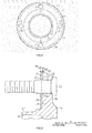
FIG. 2 is a plan view showing a hub ring according to the first embodiment; -
FIG. 3 is a sectional view showing an enlarged portion of the vehicle bearing apparatus according to the first embodiment; -
FIG. 4 is a sectional view relating to a bolt press fitting step according to the first embodiment, and showing the hub ring taken along an axle direction; -
FIG. 5 is a sectional view relating to a reference surface processing step according to the first embodiment, and showing the hub ring taken along the axle direction; -
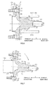
FIG. 6 is a sectional view relating to an outer surface processing step according to the first embodiment, and showing the hub ring taken along the axle direction; -
FIG. 7 is a sectional view relating to an outer surface processing step according to a virtual second manufacturing method, and showing a hub ring taken along the axle direction; -
FIG. 8 is a sectional view showing a vehicle bearing apparatus according to a second embodiment; -
FIG. 9 is a sectional view relating to a reference surface processing step according to the second embodiment, and showing the hub ring taken along the axle direction; and -
FIG. 10 is a plan view showing a hub ring according to other embodiments. - A configuration of a vehicle bearing apparatus 1 according to a first embodiment will be described with reference to
FIG. 1 to FIG. 3 . As shown inFIG. 1 , a vehicle bearing apparatus 1 includes ahub ring 10, aninner ring body 40, anouter ring member 50,rolling elements 60, afirst seal member 71, and asecond seal member 72. Thehub ring 10 and theinner ring body 40 constitute an inner ring member. - The
hub ring 10 has aseal facing surface 11,bolts 12, ashaft body portion 20, aninner side hole 25, anouter side hole 26, afitting portion 27, and aflange portion 30. Theseal facing surface 11 corresponds to a "diameter changing surface". - The
shaft body portion 20 is formed as a portion that protrudes toward a vehicle body side in an axle direction X beyond theflange portion 30. Theshaft body portion 20 has an outerperipheral surface 21, a large-diameter portion 22, a small-diameter portion 23, and astep surface 24. Theshaft body portion 20 has a columnar shape. The axle direction X coincides with an axial direction of thehub ring 10. The vehicle outer side in the axle direction X represents a side on which a brake rotor is disposed to the vehicle bearing apparatus 1. The vehicle body side in the axle direction X represents a side close to a vehicle when the vehicle bearing apparatus 1 is fitted to the vehicle. - The large-
diameter portion 22 is formed on the vehicle body side in the axle direction X beyond theflange portion 30. The outerperipheral surface 21 of the large-diameter portion 22 forms a raceway surface for therolling elements 60. The small-diameter portion 23 is formed on the vehicle body side with respect to the large-diameter portion 22 in the axle direction X. Thestep surface 24 forms a boundary between the large-diameter portion 22 and the small-diameter portion 23. Thestep surface 24 is orthogonal to the axle direction X. - The
inner side hole 25 is formed at an end portion of theshaft body portion 20 on the vehicle body side in the axle direction X. Theouter side hole 26 is formed at an end portion of theshaft body portion 20 on the vehicle outer side in the axle direction X. Thefitting portion 27 is formed as a portion that protrudes toward the vehicle outer side in the axle direction X beyond theflange portion 30. - As shown in
FIG. 2 , theflange portion 30 has athick portion 31, athin portion 34,bolt holes 37, and aperipheral groove 38. Eachbolt hole 37 extends through theflange portion 30 in the axle direction X. Thebolts 12 are press-fitted into thebolt holes 37, respectively. - The
peripheral groove 38 is formed in a surface of theflange portion 30 on the vehicle outer side in the axle direction X. Theperipheral groove 38 is formed at a position coinciding with thebolt holes 37 in a radial direction of theflange portion 30. A width of theperipheral groove 38 is larger than a diameter of eachbolt hole 37. Therefore, theentire bolt holes 37 are formed in theperipheral groove 38. An outer periphery of theperipheral groove 38 is formed on an outer peripheral side with respect to thebolt holes 37. An inner periphery of theperipheral groove 38 is formed on an inner peripheral side with respect to thebolt holes 37. - As shown in
FIG. 3 , thethick portion 31 has a thick portionouter surface 32 and a thick portioninner surface 33. Thethick portion 31 is formed in a portion of theflange portion 30, which is located on an outer side with respect to thebolt holes 37 and theperipheral groove 38 in the radial direction. The thick portionouter surface 32 forms a surface of thethick portion 31 on the vehicle outer side in the axle direction X. The thick portioninner surface 33 forms a surface of thethick portion 31 on the vehicle body side in the axle direction X. - The
thin portion 34 has a thin portionouter surface 35 and a thin portioninner surface 36. Thethin portion 34 is formed in a portion of theflange portion 30, which is located on an inner side with respect to thethick portion 31 and theperipheral groove 38 in the radial direction. A thickness of thethin portion 34 in the axle direction X is smaller than that of thethick portion 31. The thin portionouter surface 35 forms a surface of thethin portion 34 on the vehicle outer side in the axle direction X. The thin portioninner surface 36 forms a surface of thethin portion 34 on the vehicle body side in the axle direction X. - The thick portion
outer surface 32 is formed on the vehicle outer side with respect to the thin portionouter surface 35 in the axle direction X. The thick portionouter surface 32 is brought into contact with the brake rotor (not shown) when the vehicle bearing apparatus 1 is fitted to the brake rotor. The thin portionouter surface 35 faces the brake rotor across a gap when the vehicle bearing apparatus 1 is fitted to the brake rotor. - A length HA from a bottom surface of the
peripheral groove 38 to the thick portionouter surface 32 is larger than a length HB from the bottom surface of theperipheral groove 38 to the thin portionouter surface 35. A difference between the distance HA and the distance HB is set to, for example, 0.1 mm. - As shown in
FIG. 1 , theseal facing surface 11 is formed in theshaft body portion 20. Theseal facing surface 11 is formed between theflange portion 30 and the large-diameter portion 22. Theseal facing surface 11 faces afirst seal member 71. - The
inner ring body 40 has an outer peripheral surface 41 and an outerside contact surface 42. Theinner ring body 40 is press-fitted into the small-diameter portion 23. Theinner ring body 40 is disposed to abut on thestep surface 24. The outerside contact surface 42 is orthogonal to the axle direction X. The outerside contact surface 42 is in contact with thestep surface 24. - The
outer ring member 50 has an outerperipheral surface 50A, an innerperipheral surface 50B, acylindrical portion 51, and aflange portion 52. Theouter ring member 50 has a cylindrical shape. The innerperipheral surface 50B of thecylindrical portion 51 forms a raceway surface for the rollingelements 60. Theflange portion 52 protrudes toward an area outside thecylindrical portion 51. - The rolling
elements 60 form a row on the vehicle outer side and a row on the vehicle body side. The row of the rollingelements 60 on the vehicle outer side is disposed between the outerperipheral surface 21 of the large-diameter portion 22 and the innerperipheral surface 50B of theouter ring member 50. The row of the rollingelements 60 on the vehicle body side is disposed between the outer peripheral surface 41 of theinner ring body 40 and the innerperipheral surface 50B of theouter ring member 50. - The
first seal member 71 is disposed between the innerperipheral surface 50B of theouter ring member 50 and the outerperipheral surface 21 of theshaft body portion 20. Thefirst seal member 71 is disposed on the vehicle body side with respect to theflange portion 30 in the axle direction X. Thefirst seal member 71 faces theseal facing surface 11. - The
second seal member 72 is disposed between the innerperipheral surface 50B of theouter ring member 50 and the outer peripheral surface 41 of theinner ring body 40. Thesecond seal member 72 is disposed on the vehicle body side with respect to thefirst seal member 71 in the axle direction X. - A method for manufacturing the vehicle bearing apparatus 1 will be described with reference to
FIG. 4 to FIG. 6 . The method for manufacturing the vehicle bearing apparatus 1 includes a component manufacturing step, a hub ring manufacturing step, and a component assembling step. Theinner ring body 40, theouter ring member 50, the rollingelements 60, thefirst seal member 71, and thesecond seal member 72 are individually manufactured at the component manufacturing step. Anintermediate product 200 of thehub ring 10 is manufactured at an intermediate product manufacturing step. The hub ring manufacturing step includes the intermediate product manufacturing step, a bolt press fitting step, a reference surface processing step, an outer surface processing step, and a hardening step. - At the intermediate product manufacturing step, the
intermediate product 200 is manufactured.FIG. 4 shows an example of theintermediate product 200. In theintermediate product 200, theseal facing surface 11, theshaft body portion 20, and theflange portion 30 are formed by forging. In theintermediate product 200, the thin portionouter surface 35 and theperipheral groove 38 are formed in theflange portion 30 by turning and the like. -
FIG. 4 shows a working state in the bolt press fitting step. Thebolts 12 are press-fitted into the bolt holes 37, respectively. At this time, the thick portionouter surface 32 and the thin portionouter surface 35 may be warped by press fitting of thebolts 12. -
FIG. 5 shows a working state in the reference surface processing step. Theseal facing surface 11 and the outerperipheral surface 21 are ground. Asupport apparatus 82 is fitted onto thefitting portion 27, and hence theintermediate product 200 is supported from the vehicle outer side in the axle direction X. Arotating apparatus 83 is disposed to abut on theinner side hole 25 in theintermediate product 200. Agrindstone 81 is disposed to be in contact with a portion of the outerperipheral surface 21, the portion extending from theseal facing surface 11 to thestep surface 24, in theintermediate product 200. Thegrindstone 81 has a shape corresponding to the portion of the outerperipheral surface 21, the portion extending from theseal facing surface 11 to thestep surface 24. Theintermediate product 200 is supported by thesupport apparatus 82 and rotated by the rotatingapparatus 83 while being in contact with thegrindstone 81. As a result, theintermediate product 200 is ground. Since theseal facing surface 11 is subjected to grinding, theseal facing surface 11 is orthogonal to the axle direction X. -
FIG. 6 shows a working state in the outer surface processing step. The thick portionouter surface 32 is subjected to turning. Therotating apparatus 83 is disposed to abut on theinner side hole 25 in theintermediate product 200. A plurality of rod-shapedmembers 84A of abackup apparatus 84 are disposed to abut on theseal facing surface 11 from the vehicle body side in the axle direction X, in theintermediate product 200. A distal end portion of each rod-shapedmember 84A is disposed on a virtual plane C orthogonal to the axle direction X. Therefore, theintermediate product 200 is maintained in a state in which theseal facing surface 11 is orthogonal to the axle direction X, by thebackup apparatus 84. A turningsurface 91 of aturning apparatus 90 is disposed to abut on the thick portionouter surface 32, in theintermediate product 200. The turningapparatus 90 performs turning on the thick portionouter surface 32 while using theseal facing surface 11 as a reference surface. The turningsurface 91 of the turningapparatus 90 is orthogonal to the axle direction X. At this time, theintermediate product 200 is sandwiched between the turningsurface 91 and the rod-shapedmembers 84A from both sides in the axle direction X. Theintermediate product 200 is rotated by the rotatingapparatus 83. At this time, turning is performed on theintermediate product 200 by the turningapparatus 90. Since the thick portionouter surface 32 is subjected to turning, a degree of parallelism of the thick portionouter surface 32 relative to the reference surface is increased. Turning corresponds to "machining". - At the hardening step, induction hardening is performed on the outer
peripheral surface 21 of theintermediate product 200. At the hardening step, thehub ring 10 is manufactured. At the component assembling step, theinner ring body 40, theouter ring member 50, the rollingelements 60, thefirst seal member 71, and thesecond seal member 72 are fitted to thehub ring 10. Theinner ring body 40 is press-fitted into the small-diameter portion 23 from the vehicle body side in the axle direction X and disposed to abut on thestep surface 24 of thehub ring 10. Thefirst seal member 71 is disposed in a portion facing theseal facing surface 11. The rollingelements 60 and theouter ring member 50 are disposed around the outer periphery of theinner ring body 40 and theshaft body portion 20. After theinner ring body 40 is press-fitted onto the small-diameter portion 23, the end portion of thehub ring 10 on the vehicle body side in the axle direction X is clinched. As a result, the end portion of thehub ring 10 on the vehicle body side is deformed into the shape shown inFIG. 1 . The vehicle bearing apparatus 1 shown inFIG. 1 is manufactured through the component assembling step. - A function of the vehicle bearing apparatus 1 will be described. The thick portion
outer surface 32 may be warped due to press fitting of thebolts 12. On the other hand, the thick portion processing step is performed after the bolt press fitting step. Therefore, the warp of the thick portionouter surface 32 caused due to the press fitting of thebolts 12 is reduced. - The vehicle bearing apparatus 1 and the manufacturing method thereof provide the following effects. (1) According to the method for manufacturing the
hub ring 10, the outer surface processing step is performed after the bolt press fitting step. Therefore, the warp of the thick portionouter surface 32 caused due to the press fitting of thebolts 12 is reduced. Therefore, flange runout is suppressed. - (2) The method for manufacturing the
hub ring 10 provides the advantageous effect as compared with a virtual first manufacturing method. The virtual first manufacturing method is different from the method for manufacturing the vehicle bearing apparatus 1 in the following point, but the virtual first manufacturing method has the same contents as those of the method for manufacturing the vehicle bearing apparatus 1 in any other point. According to the virtual first manufacturing method, turning is performed on the thick portionouter surface 32, by using, as the reference surface, theseal facing surface 11 that has not been subjected to the reference surface processing step with the use of grinding. When turning is performed, a contact position of the distal end portion of each rod-shapedmember 84A on theseal facing surface 11 varies in accordance with rotation of theintermediate product 200. In the virtual first manufacturing method using theseal facing surface 11, which has not been subjected to grinding, as the reference surface, the degree of unevenness of theseal facing surface 11 is large. Therefore, theintermediate product 200 is likely to be moved in the axle direction X due to the rotation and theintermediate product 200 is likely to be inclined relative to the axle direction X due to the rotation. - On the other hand, according to the method for manufacturing the
hub ring 10, turning is performed on the thick portionouter surface 32 using theseal facing surface 11 subjected to grinding as the reference surface. A degree of parallelism of theseal facing surface 11 with respect to the surface orthogonal to the axle direction X has been improved due to grinding. In other words, the unevenness of theseal facing surface 11 is reduced due to grinding. Therefore, in the method for manufacturing thehub ring 10, theintermediate product 200 is less likely to be moved in the axle direction X due to the rotation and theintermediate product 200 is less likely to be inclined relative to the axle direction X due to the rotation, as compared to the virtual first manufacturing method. Therefore, it is possible to increase the degree of parallelism of the thick portionouter surface 32 with respect to the surface orthogonal to the axle direction X as compared to the virtual first manufacturing method. Therefore, it is possible to more appropriately suppress the flange runout. - (3) The
thick portion 31 is formed in the portion of theflange portion 30, which is located on the outer side with respect to the bolt holes 37. Therefore, it is possible to easily perform turning with the use of the turningapparatus 90. (4) The thick portionouter surface 32 is subjected to machining by using theseal facing surface 11 orthogonal to the axle direction X as the reference surface. Therefore, it is possible to improve a processing accuracy for the thick portionouter surface 32. - The method for manufacturing the
hub ring 10 provides the advantageous effect as compared to a virtual second manufacturing method. The virtual second manufacturing method is different from the method for manufacturing the vehicle bearing apparatus 1 in the following point, but the virtual second manufacturing method has the same contents as those of the method for manufacturing the vehicle bearing apparatus 1 in any other point. As shown inFIG. 7 , at an outer surface processing step in the virtual second manufacturing method, theintermediate product 200 is supported at the inner peripheral surface of theintermediate product 200, which defines theouter side hole 26, by using asupport apparatus 184. At the outer surface processing step in the virtual second manufacturing method, turning is performed on the thick portionouter surface 32 by using, as a reference surface, the inner peripheral surface defining theouter side hole 26, which is supported by thesupport apparatus 184. At this time, if there is a difference between an outside diameter of thesupport apparatus 184 and an inside diameter of the inner peripheral surface defining theouter side hole 26, a gap is formed between an outer peripheral surface of thesupport apparatus 184 and the inner peripheral surface defining theouter side hole 26. Therefore, as shown inFIG. 7 , theshaft body portion 20 may be inclined during turning. If turning is performed in a state in which theshaft body portion 20 is inclined, the thick portionouter surface 32 is inclined relative to the axle direction X. Therefore, the effect for suppressing the flange runout may be reduced. Thesupport apparatus 184 in the virtual second manufacturing method supports the inner peripheral surface defining theouter side hole 26, but it is considered that the same problem may occur in a configuration where the outerperipheral surface 21 and the inner peripheral surface defining theinner side hole 25 are supported. - On the other hand, according to the method for manufacturing the vehicle bearing apparatus 1, at the outer surface processing step, the
seal facing surface 11 of theintermediate product 200 is supported by the rod-shapedmembers 84A, and turning is performed on the thick portionouter surface 32 of theintermediate product 200 by using the turningsurface 91. As described above, theintermediate product 200 is subjected to turning in a state in which theseal facing surface 11 and the thick portionouter surface 32 are supported from both sides in the axle direction X. Therefore, in the method for manufacturing the vehicle bearing apparatus 1, theshaft body portion 20 is not likely to be inclined at the outer surface processing step, unlike in the virtual second manufacturing method. Therefore, a processing accuracy for the thick portionouter surface 32 is improved. - (5) The degree of warp caused due to the press fitting of the
bolts 12 increases toward the bolt holes 37. Thehub ring 10 has theperipheral groove 38. The outer periphery of theperipheral groove 38 is formed on the outer peripheral side with respect to the bolt holes 37. Therefore, it is possible to reduce the warp of the thick portionouter surface 32 by the press fitting of thebolts 12. - A vehicle bearing apparatus 1 according to a second embodiment has a configuration that is different from the configuration of the vehicle bearing apparatus 1 according to the first embodiment in the following portions, and that is the same as the configuration of the vehicle bearing apparatus 1 according to the first embodiment in any other portion. In a description of the vehicle bearing apparatus 1 according to the second embodiment, the same reference numerals as those in the vehicle bearing apparatus 1 according to the first embodiment are assigned to the same portions as those of the vehicle bearing apparatus 1 according to the first embodiment.
- As shown in
FIG. 8 , thevehicle bearing apparatus 100 according to the second embodiment includes ahub ring 110, aninner ring body 140, anouter ring member 50, rollingelements 60, afirst seal member 71, and asecond seal member 72. - The
hub ring 110 includes an innerring facing surface 111,bolts 12, ashaft body portion 120, and aflange portion 30. Theshaft body portion 120 has an outerperipheral surface 121. Theshaft body portion 120 has a columnar shape. The innerring facing surface 111 faces thefirst seal member 71 and theinner ring body 140. The innerring facing surface 111 corresponds to a "diameter changing surface", a "step surface", and a "seal facing surface". - The
inner ring body 140 has an outerperipheral surface 141 and an outerside contact surface 142. Theinner ring body 140 is press-fitted into theshaft body portion 20. Theinner ring body 140 is disposed to abut on the innerring facing surface 111. The outerside contact surface 142 is orthogonal to the axle direction X. The outerside contact surface 142 is in contact with the innerring facing surface 111. - A row of the rolling
elements 60 on the vehicle outer side and a row of the rollingelements 60 on the vehicle body side are disposed between the outerperipheral surface 141 of theinner ring body 140 and an innerperipheral surface 50B of theouter ring member 50. Thefirst seal member 71 is disposed between the innerperipheral surface 50B of theouter ring member 50 and the outerperipheral surface 141 of theinner ring body 140. Thefirst seal member 71 faces the innerring facing surface 111. Thesecond seal member 72 is disposed between the innerperipheral surface 50B of theouter ring member 50 and the outerperipheral surface 141 of theinner ring body 140. - A method for manufacturing the vehicle bearing apparatus 1 will be described with reference to
FIG. 9. FIG. 9 shows a working state in a reference surface processing step. The innerring facing surface 111 is ground by using agrindstone 381, asupport apparatus 82, and arotating apparatus 83. Thegrindstone 381 corresponds to the innerring facing surface 111 and a portion of the outerperipheral surface 122 in theintermediate product 300, the portion being located on the vehicle body side with respect to the innerring facing surface 111 in the axle direction X. Since the innerring facing surface 111 is subjected to grinding, the innerring facing surface 111 is orthogonal to the axle direction X. - A thick portion
outer surface 32 is subjected to turning by a turning apparatus 90 (seeFIG. 6 ) at an outer surface processing step. Each rod-shapedmember 84A (seeFIG. 6 ) is disposed to abut on the innerring facing surface 111 orthogonal to the axle direction X from the vehicle body side in the axle direction X at the reference surface processing step. The thick portionouter surface 32 is subjected to turning by using the innerring facing surface 111 as the reference surface. Since the thick portionouter surface 32 is subjected to turning, the thick portionouter surface 32 is parallel to the reference surface and orthogonal to the axle direction X. - The vehicle bearing apparatus 1 according to the second embodiment provides substantially the same effects as the effect (1) provided by the vehicle bearing apparatus 1 according to the first embodiment, i.e., the effect of suppressing the flange runout and the effects (2) to (5) provided by the vehicle bearing apparatus 1 according to the first embodiment.
- The method for manufacturing the vehicle bearing apparatus according to the invention includes embodiments other than the respective foregoing embodiments. Modified examples of the respective foregoing embodiments will be described as other embodiments of the method for manufacturing the vehicle bearing apparatus according to the invention. The following modified examples can be combined with each other.
- The thick portion
outer surface 32 according to the first embodiment is subjected to turning by using theseal facing surface 11 as the reference surface. However, the processing method for the thick portionouter surface 32 is not restricted to that exemplified in the first embodiment. For example, the thick portionouter surface 32 according to a modified example is subjected to turning by using thestep surface 24 as the reference surface. Since thisstep surface 24 is ground at the reference surface processing step, thestep surface 24 is orthogonal to the axle direction X. - The vehicle bearing apparatus 1 according to the second embodiment includes one
inner ring body 140. However, the configuration of theinner ring body 140 is not restricted to that exemplified in the second embodiment. For example, theinner ring body 140 in the vehicle bearing apparatus 1 according to a modified example includes a first portion and a second portion that are different bodies. The first portion has a raceway surface for the row of the rollingelements 60 on the vehicle outer side. The second portion has a raceway surface for the row on the vehicle body side. - The thick portion
outer surface 32 according to each embodiment is subjected to turning by using a surface orthogonal to the axle direction X as the reference surface. However, the processing method for the thick portionouter surface 32 is not restricted to that exemplified in each embodiment. For example, the thick portionouter surface 32 according to a modified example is subjected to turning by using a surface parallel to the axle direction X as the reference surface. As the surface parallel to the axle direction X, for example, the outerperipheral surface shaft body portion peripheral surface shaft body portion - The thick portion
outer surface 32 according to each embodiment is subjected to turning at the outer surface processing step. However, the processing method for the thick portionouter surface 32 is not restricted to that exemplified in each embodiment. For example, the thick portionouter surface 32 according to a modified example is ground at the outer surface processing step. In short, it is possible to employ an arbitrary processing method as the processing method for the thick portionouter surface 32 as long as the method is a machining method that makes it possible to reduce warp of the thick portionouter surface 32. - According to the method for manufacturing the vehicle bearing apparatus 1 of each embodiment, the
support apparatus 82 is fitted onto thefitting portion 27, and therotating apparatus 83 is inserted into theinner side hole 25. However, the method for manufacturing the vehicle bearing apparatus 1 is not restricted to this method. For example, according to the method for manufacturing the vehicle bearing apparatus 1 of a modified example, thesupport apparatus 82 is inserted into theinner side hole 25, and therotating apparatus 83 is fitted onto thefitting portion 27. In short, the configurations of thesupport apparatus 82 and therotating apparatus 83 may be appropriately changed as long as thesupport apparatus 82 and therotating apparatus 83 are able to support and rotate theintermediate product - The
flange portion 30 according to each embodiment has the circular shape. However, the shape of theflange portion 30 is not restricted to that exemplified in each embodiment. For example, theflange portion 30 according to a modified example shown inFIG. 10 has thinned portions. Each thinned portion is formed at a part between the bolt holes 37 adjacent to each other on the circumference of theflange portion 30. - The method for manufacturing a hub ring and the method for manufacturing a vehicle bearing apparatus according to the invention make it possible to suppress the flange runout.
Claims (4)
- A method for manufacturing a hub ring, the hub ring including a flange portion and a shaft body portion, the flange portion including bolt holes, an outer surface, and bolts and being formed on an outer periphery of the shaft body portion, the bolts being press-fitted into the bolt holes, respectively, and the outer surface forming a surface of the flange portion on a vehicle outer side in an axle direction, the method by comprising:press-fitting the bolts into the bolt holes, respectively;forming a reference surface in the shaft body portion by performing grinding on the shaft body portion, the reference surface being orthogonal to or parallel to the axle direction; andperforming machining on the outer surface by using the reference surface as a reference, after the bolts are press-fitted into the bolt holes, respectively.
- The method according to claim 1, wherein the hub ring manufactured by the method for manufacturing the hub ring has a diameter changing surface whose outside diameter is reduced on a vehicle body side with respect to the flange portion in the axle direction, and the reference surface orthogonal to the axle direction is formed by performing grinding on the diameter changing surface.
- The method according to claim 1 or 2, wherein the flange portion has a thick portion and a thin portion, the outer surface has a thick portion outer surface and a thin portion outer surface, the thick portion is formed in a portion of the flange portion, which is located on an outer side with respect to the bolt holes, the thin portion is formed in a portion of the flange portion, which is located on an inner side with respect to the thick portion, a thickness of the thin portion in the axle direction is smaller than that of the thick portion, the thick portion outer surface forms a surface of the thick portion on the vehicle outer side in the axle direction, the thin portion outer surface forms a surface of the thin portion on the vehicle outer side in the axle direction, and machining is performed on the thick portion outer surface by using the reference surface as the reference, after the bolts are press-fitted into the bolt holes, respectively.
- A method for manufacturing a vehicle bearing apparatus, the vehicle bearing apparatus including a hub ring, an inner ring body, an outer ring member, rolling elements, and a seal member, the hub ring including a flange portion, a shaft body portion, a step surface, and a seal facing surface, the flange portion including bolt holes, an outer surface, and bolts and being formed on an outer periphery of the shaft body portion, and the outer surface forming a surface of the flange portion on a vehicle outer side in an axle direction, the method comprising:press-fitting the bolts into the bolt holes, respectively;forming a reference surface in the shaft body portion by performing grinding on the seal facing surface or the step surface, the reference surface being orthogonal to the axle direction;performing machining on the outer surface by using the reference surface as a reference after the bolts are press-fitted into the bolt holes, respectively; anddisposing the inner ring body so that the inner ring body abuts on the step surface of the manufactured hub ring in the axle direction, disposing the seal member in a portion facing the seal facing surface, and disposing the rolling elements and the outer ring member around an outer periphery of the inner ring body and the shaft body portion.
Applications Claiming Priority (1)
| Application Number | Priority Date | Filing Date | Title |
|---|---|---|---|
| JP2013028229A JP6107205B2 (en) | 2013-02-15 | 2013-02-15 | Hub wheel manufacturing method and vehicle bearing device manufacturing method |
Publications (2)
| Publication Number | Publication Date |
|---|---|
| EP2767411A1 true EP2767411A1 (en) | 2014-08-20 |
| EP2767411B1 EP2767411B1 (en) | 2016-09-14 |
Family
ID=50101714
Family Applications (1)
| Application Number | Title | Priority Date | Filing Date |
|---|---|---|---|
| EP14154426.2A Not-in-force EP2767411B1 (en) | 2013-02-15 | 2014-02-10 | Method for manufacturing hub ring and method for manufacturing vehicle bearing apparatus |
Country Status (4)
| Country | Link |
|---|---|
| US (2) | US20140230249A1 (en) |
| EP (1) | EP2767411B1 (en) |
| JP (1) | JP6107205B2 (en) |
| CN (1) | CN103991332B (en) |
Families Citing this family (9)
| Publication number | Priority date | Publication date | Assignee | Title |
|---|---|---|---|---|
| JP6449689B2 (en) * | 2015-03-11 | 2019-01-09 | Ntn株式会社 | Wheel bearing device |
| JP6587851B2 (en) * | 2015-07-16 | 2019-10-09 | Ntn株式会社 | Wheel bearing device |
| ITUA20162986A1 (en) * | 2016-04-28 | 2017-10-28 | Skf Ab | Flanged wheel hub for wheel hub bearings. |
| JP7047389B2 (en) * | 2018-01-12 | 2022-04-05 | 株式会社ジェイテクト | Wheel bearing device and its manufacturing method |
| JP7047388B2 (en) * | 2018-01-12 | 2022-04-05 | 株式会社ジェイテクト | Wheel bearing device and its manufacturing method |
| CN108381312B (en) * | 2018-02-12 | 2020-09-11 | 江苏三州机械科技有限公司 | Hardware circular plate polishing equipment |
| CN109531285A (en) * | 2018-12-11 | 2019-03-29 | 贵州天马虹山轴承有限公司 | A kind of processing technology of Special-shaped bearing |
| JP7330707B2 (en) * | 2019-01-25 | 2023-08-22 | Ntn株式会社 | Manufacturing method of wheel bearing device |
| IT201900023205A1 (en) * | 2019-12-06 | 2021-06-06 | Skf Ab | SUSPENSION ASSEMBLY FOR VEHICLES, INCLUDING A WHEEL HUB UNIT AND A SUSPENSION POST OR JOINT |
Citations (3)
| Publication number | Priority date | Publication date | Assignee | Title |
|---|---|---|---|---|
| JP2001334803A (en) * | 2000-05-29 | 2001-12-04 | Koyo Seiko Co Ltd | Bearing device for axle |
| EP1288021A2 (en) * | 2001-09-04 | 2003-03-05 | Ntn Corporation | A bearing apparatus for wheel |
| JP2003154801A (en) * | 2001-09-04 | 2003-05-27 | Ntn Corp | Bearing device for wheel |
Family Cites Families (13)
| Publication number | Priority date | Publication date | Assignee | Title |
|---|---|---|---|---|
| JP3973317B2 (en) * | 1999-04-22 | 2007-09-12 | Ntn株式会社 | Manufacturing method of wheel bearing device |
| JP3622103B2 (en) | 1997-12-16 | 2005-02-23 | 光洋精工株式会社 | Method for assembling wheel bearing device |
| JP4699977B2 (en) * | 1998-11-11 | 2011-06-15 | Ntn株式会社 | Wheel bearing device |
| KR20000035349A (en) | 1998-11-11 | 2000-06-26 | 이토오 도요아키 | Automotive wheel bearing assembly and method for manufacturing the same |
| US6415508B1 (en) * | 1999-06-09 | 2002-07-09 | The Timken Company | Hub assembly having minimum runout and process for producing the same |
| EP1588868A4 (en) * | 2003-01-29 | 2006-12-13 | Nsk Ltd | Wheel bearing unit and method of manufacturing the bearing unit |
| US6829825B1 (en) * | 2003-01-31 | 2004-12-14 | Robert Bosch Corporation | Process of manufacturing a corner assembly |
| JP4062316B2 (en) * | 2005-03-28 | 2008-03-19 | 株式会社ジェイテクト | Manufacturing method of axle bearing device |
| JP2007024273A (en) * | 2005-07-20 | 2007-02-01 | Ntn Corp | Manufacturing method of wheel bearing device |
| JP2010105439A (en) * | 2008-10-28 | 2010-05-13 | Jtekt Corp | Wheel bearing device and method of manufacturing the same |
| JP5477028B2 (en) * | 2009-02-17 | 2014-04-23 | 株式会社ジェイテクト | Manufacturing method of wheel bearing device |
| US20100210369A1 (en) | 2009-02-17 | 2010-08-19 | Jtekt Corporation | Wheel bearing device and manufacturing method therefor |
| CN102430965A (en) * | 2011-10-11 | 2012-05-02 | 洛阳Lyc轴承有限公司 | Method for grinding and positioning inner ring of third-generation wheel hub bearing |
-
2013
- 2013-02-15 JP JP2013028229A patent/JP6107205B2/en not_active Expired - Fee Related
-
2014
- 2014-02-10 US US14/176,620 patent/US20140230249A1/en not_active Abandoned
- 2014-02-10 EP EP14154426.2A patent/EP2767411B1/en not_active Not-in-force
- 2014-02-13 CN CN201410049712.2A patent/CN103991332B/en not_active Expired - Fee Related
-
2016
- 2016-12-28 US US15/392,129 patent/US10207537B2/en not_active Expired - Fee Related
Patent Citations (3)
| Publication number | Priority date | Publication date | Assignee | Title |
|---|---|---|---|---|
| JP2001334803A (en) * | 2000-05-29 | 2001-12-04 | Koyo Seiko Co Ltd | Bearing device for axle |
| EP1288021A2 (en) * | 2001-09-04 | 2003-03-05 | Ntn Corporation | A bearing apparatus for wheel |
| JP2003154801A (en) * | 2001-09-04 | 2003-05-27 | Ntn Corp | Bearing device for wheel |
Also Published As
| Publication number | Publication date |
|---|---|
| JP6107205B2 (en) | 2017-04-05 |
| CN103991332A (en) | 2014-08-20 |
| JP2014156197A (en) | 2014-08-28 |
| EP2767411B1 (en) | 2016-09-14 |
| CN103991332B (en) | 2018-02-09 |
| US20140230249A1 (en) | 2014-08-21 |
| US10207537B2 (en) | 2019-02-19 |
| US20170106695A1 (en) | 2017-04-20 |
Similar Documents
| Publication | Publication Date | Title |
|---|---|---|
| EP2767411B1 (en) | Method for manufacturing hub ring and method for manufacturing vehicle bearing apparatus | |
| KR20160118955A (en) | Method of producing wheel bearing apparatus | |
| US20150003770A1 (en) | Rolling bearing, in particular for a steering column, and associated production method | |
| US20120189236A1 (en) | Wheel rolling bearing device | |
| WO2019026358A1 (en) | Hub unit bearing, method for manufacturing same, motor vehicle, and method for manufacturing same | |
| JP2015128924A (en) | Bearing module | |
| CN101516639A (en) | Hub wheel, hub unit, and method of working hub wheel | |
| JP6186833B2 (en) | Rolling bearing with seal ring | |
| EP2587078A1 (en) | Wheel bearing device | |
| JP2022097522A (en) | Hub unit bearing manufacturing method | |
| JP2005140192A (en) | Bearing device for wheel | |
| JP5935373B2 (en) | Hub unit | |
| US20130062929A1 (en) | Hub unit | |
| EP2618162A1 (en) | Wheel rolling bearing device with integrated speed detector | |
| CN108026971B (en) | Wheel bearing device | |
| CN108026963A (en) | The manufacture method of bearing apparatus for wheel | |
| JP2015205649A (en) | bearing unit | |
| JP4771114B2 (en) | Hub unit | |
| KR20140118934A (en) | A Double-Row Angular Contact Ball Bearing Having Flange | |
| JP7701776B2 (en) | Wheel bearing device and method for manufacturing the wheel bearing device | |
| JP2020143699A (en) | Bearing device for wheel | |
| JP2016102544A (en) | Bearing for wheel support | |
| JP6601154B2 (en) | Hub unit bearing | |
| US8814435B2 (en) | Bearing unit | |
| KR101569317B1 (en) | A Double-Row Angular Contact Ball Bearing Having Flange |
Legal Events
| Date | Code | Title | Description |
|---|---|---|---|
| PUAI | Public reference made under article 153(3) epc to a published international application that has entered the european phase |
Free format text: ORIGINAL CODE: 0009012 |
|
| 17P | Request for examination filed |
Effective date: 20140210 |
|
| AK | Designated contracting states |
Kind code of ref document: A1 Designated state(s): AL AT BE BG CH CY CZ DE DK EE ES FI FR GB GR HR HU IE IS IT LI LT LU LV MC MK MT NL NO PL PT RO RS SE SI SK SM TR |
|
| AX | Request for extension of the european patent |
Extension state: BA ME |
|
| R17P | Request for examination filed (corrected) |
Effective date: 20141001 |
|
| RBV | Designated contracting states (corrected) |
Designated state(s): AL AT BE BG CH CY CZ DE DK EE ES FI FR GB GR HR HU IE IS IT LI LT LU LV MC MK MT NL NO PL PT RO RS SE SI SK SM TR |
|
| GRAP | Despatch of communication of intention to grant a patent |
Free format text: ORIGINAL CODE: EPIDOSNIGR1 |
|
| INTG | Intention to grant announced |
Effective date: 20160323 |
|
| GRAS | Grant fee paid |
Free format text: ORIGINAL CODE: EPIDOSNIGR3 |
|
| GRAA | (expected) grant |
Free format text: ORIGINAL CODE: 0009210 |
|
| RIN1 | Information on inventor provided before grant (corrected) |
Inventor name: MORITA, KENICHI Inventor name: KOTANI, RYOICHIRO Inventor name: KOMATSU, HIROYOSHI Inventor name: KATSUYAMA, YUU Inventor name: SASAKI, TORU |
|
| AK | Designated contracting states |
Kind code of ref document: B1 Designated state(s): AL AT BE BG CH CY CZ DE DK EE ES FI FR GB GR HR HU IE IS IT LI LT LU LV MC MK MT NL NO PL PT RO RS SE SI SK SM TR |
|
| REG | Reference to a national code |
Ref country code: GB Ref legal event code: FG4D |
|
| REG | Reference to a national code |
Ref country code: CH Ref legal event code: EP |
|
| REG | Reference to a national code |
Ref country code: IE Ref legal event code: FG4D |
|
| REG | Reference to a national code |
Ref country code: AT Ref legal event code: REF Ref document number: 828517 Country of ref document: AT Kind code of ref document: T Effective date: 20161015 |
|
| REG | Reference to a national code |
Ref country code: DE Ref legal event code: R096 Ref document number: 602014003557 Country of ref document: DE |
|
| REG | Reference to a national code |
Ref country code: LT Ref legal event code: MG4D |
|
| REG | Reference to a national code |
Ref country code: NL Ref legal event code: MP Effective date: 20160914 |
|
| PG25 | Lapsed in a contracting state [announced via postgrant information from national office to epo] |
Ref country code: HR Free format text: LAPSE BECAUSE OF FAILURE TO SUBMIT A TRANSLATION OF THE DESCRIPTION OR TO PAY THE FEE WITHIN THE PRESCRIBED TIME-LIMIT Effective date: 20160914 Ref country code: LT Free format text: LAPSE BECAUSE OF FAILURE TO SUBMIT A TRANSLATION OF THE DESCRIPTION OR TO PAY THE FEE WITHIN THE PRESCRIBED TIME-LIMIT Effective date: 20160914 Ref country code: FI Free format text: LAPSE BECAUSE OF FAILURE TO SUBMIT A TRANSLATION OF THE DESCRIPTION OR TO PAY THE FEE WITHIN THE PRESCRIBED TIME-LIMIT Effective date: 20160914 Ref country code: RS Free format text: LAPSE BECAUSE OF FAILURE TO SUBMIT A TRANSLATION OF THE DESCRIPTION OR TO PAY THE FEE WITHIN THE PRESCRIBED TIME-LIMIT Effective date: 20160914 Ref country code: NO Free format text: LAPSE BECAUSE OF FAILURE TO SUBMIT A TRANSLATION OF THE DESCRIPTION OR TO PAY THE FEE WITHIN THE PRESCRIBED TIME-LIMIT Effective date: 20161214 |
|
| REG | Reference to a national code |
Ref country code: AT Ref legal event code: MK05 Ref document number: 828517 Country of ref document: AT Kind code of ref document: T Effective date: 20160914 |
|
| PG25 | Lapsed in a contracting state [announced via postgrant information from national office to epo] |
Ref country code: NL Free format text: LAPSE BECAUSE OF FAILURE TO SUBMIT A TRANSLATION OF THE DESCRIPTION OR TO PAY THE FEE WITHIN THE PRESCRIBED TIME-LIMIT Effective date: 20160914 Ref country code: GR Free format text: LAPSE BECAUSE OF FAILURE TO SUBMIT A TRANSLATION OF THE DESCRIPTION OR TO PAY THE FEE WITHIN THE PRESCRIBED TIME-LIMIT Effective date: 20161215 Ref country code: LV Free format text: LAPSE BECAUSE OF FAILURE TO SUBMIT A TRANSLATION OF THE DESCRIPTION OR TO PAY THE FEE WITHIN THE PRESCRIBED TIME-LIMIT Effective date: 20160914 Ref country code: SE Free format text: LAPSE BECAUSE OF FAILURE TO SUBMIT A TRANSLATION OF THE DESCRIPTION OR TO PAY THE FEE WITHIN THE PRESCRIBED TIME-LIMIT Effective date: 20160914 |
|
| PG25 | Lapsed in a contracting state [announced via postgrant information from national office to epo] |
Ref country code: EE Free format text: LAPSE BECAUSE OF FAILURE TO SUBMIT A TRANSLATION OF THE DESCRIPTION OR TO PAY THE FEE WITHIN THE PRESCRIBED TIME-LIMIT Effective date: 20160914 Ref country code: RO Free format text: LAPSE BECAUSE OF FAILURE TO SUBMIT A TRANSLATION OF THE DESCRIPTION OR TO PAY THE FEE WITHIN THE PRESCRIBED TIME-LIMIT Effective date: 20160914 |
|
| PG25 | Lapsed in a contracting state [announced via postgrant information from national office to epo] |
Ref country code: AT Free format text: LAPSE BECAUSE OF FAILURE TO SUBMIT A TRANSLATION OF THE DESCRIPTION OR TO PAY THE FEE WITHIN THE PRESCRIBED TIME-LIMIT Effective date: 20160914 Ref country code: ES Free format text: LAPSE BECAUSE OF FAILURE TO SUBMIT A TRANSLATION OF THE DESCRIPTION OR TO PAY THE FEE WITHIN THE PRESCRIBED TIME-LIMIT Effective date: 20160914 Ref country code: PT Free format text: LAPSE BECAUSE OF FAILURE TO SUBMIT A TRANSLATION OF THE DESCRIPTION OR TO PAY THE FEE WITHIN THE PRESCRIBED TIME-LIMIT Effective date: 20170116 Ref country code: BG Free format text: LAPSE BECAUSE OF FAILURE TO SUBMIT A TRANSLATION OF THE DESCRIPTION OR TO PAY THE FEE WITHIN THE PRESCRIBED TIME-LIMIT Effective date: 20161214 Ref country code: SM Free format text: LAPSE BECAUSE OF FAILURE TO SUBMIT A TRANSLATION OF THE DESCRIPTION OR TO PAY THE FEE WITHIN THE PRESCRIBED TIME-LIMIT Effective date: 20160914 Ref country code: BE Free format text: LAPSE BECAUSE OF FAILURE TO SUBMIT A TRANSLATION OF THE DESCRIPTION OR TO PAY THE FEE WITHIN THE PRESCRIBED TIME-LIMIT Effective date: 20160914 Ref country code: CZ Free format text: LAPSE BECAUSE OF FAILURE TO SUBMIT A TRANSLATION OF THE DESCRIPTION OR TO PAY THE FEE WITHIN THE PRESCRIBED TIME-LIMIT Effective date: 20160914 Ref country code: IS Free format text: LAPSE BECAUSE OF FAILURE TO SUBMIT A TRANSLATION OF THE DESCRIPTION OR TO PAY THE FEE WITHIN THE PRESCRIBED TIME-LIMIT Effective date: 20170114 Ref country code: SK Free format text: LAPSE BECAUSE OF FAILURE TO SUBMIT A TRANSLATION OF THE DESCRIPTION OR TO PAY THE FEE WITHIN THE PRESCRIBED TIME-LIMIT Effective date: 20160914 Ref country code: PL Free format text: LAPSE BECAUSE OF FAILURE TO SUBMIT A TRANSLATION OF THE DESCRIPTION OR TO PAY THE FEE WITHIN THE PRESCRIBED TIME-LIMIT Effective date: 20160914 |
|
| REG | Reference to a national code |
Ref country code: DE Ref legal event code: R097 Ref document number: 602014003557 Country of ref document: DE |
|
| PG25 | Lapsed in a contracting state [announced via postgrant information from national office to epo] |
Ref country code: IT Free format text: LAPSE BECAUSE OF FAILURE TO SUBMIT A TRANSLATION OF THE DESCRIPTION OR TO PAY THE FEE WITHIN THE PRESCRIBED TIME-LIMIT Effective date: 20160914 |
|
| PLBE | No opposition filed within time limit |
Free format text: ORIGINAL CODE: 0009261 |
|
| STAA | Information on the status of an ep patent application or granted ep patent |
Free format text: STATUS: NO OPPOSITION FILED WITHIN TIME LIMIT |
|
| PG25 | Lapsed in a contracting state [announced via postgrant information from national office to epo] |
Ref country code: DK Free format text: LAPSE BECAUSE OF FAILURE TO SUBMIT A TRANSLATION OF THE DESCRIPTION OR TO PAY THE FEE WITHIN THE PRESCRIBED TIME-LIMIT Effective date: 20160914 |
|
| 26N | No opposition filed |
Effective date: 20170615 |
|
| PG25 | Lapsed in a contracting state [announced via postgrant information from national office to epo] |
Ref country code: MC Free format text: LAPSE BECAUSE OF FAILURE TO SUBMIT A TRANSLATION OF THE DESCRIPTION OR TO PAY THE FEE WITHIN THE PRESCRIBED TIME-LIMIT Effective date: 20160914 |
|
| REG | Reference to a national code |
Ref country code: CH Ref legal event code: PL |
|
| PG25 | Lapsed in a contracting state [announced via postgrant information from national office to epo] |
Ref country code: CH Free format text: LAPSE BECAUSE OF NON-PAYMENT OF DUE FEES Effective date: 20170228 Ref country code: LI Free format text: LAPSE BECAUSE OF NON-PAYMENT OF DUE FEES Effective date: 20170228 |
|
| REG | Reference to a national code |
Ref country code: IE Ref legal event code: MM4A |
|
| PG25 | Lapsed in a contracting state [announced via postgrant information from national office to epo] |
Ref country code: SI Free format text: LAPSE BECAUSE OF FAILURE TO SUBMIT A TRANSLATION OF THE DESCRIPTION OR TO PAY THE FEE WITHIN THE PRESCRIBED TIME-LIMIT Effective date: 20160914 |
|
| REG | Reference to a national code |
Ref country code: FR Ref legal event code: ST Effective date: 20171031 |
|
| PG25 | Lapsed in a contracting state [announced via postgrant information from national office to epo] |
Ref country code: LU Free format text: LAPSE BECAUSE OF NON-PAYMENT OF DUE FEES Effective date: 20170210 |
|
| PG25 | Lapsed in a contracting state [announced via postgrant information from national office to epo] |
Ref country code: FR Free format text: LAPSE BECAUSE OF NON-PAYMENT OF DUE FEES Effective date: 20170228 |
|
| PG25 | Lapsed in a contracting state [announced via postgrant information from national office to epo] |
Ref country code: IE Free format text: LAPSE BECAUSE OF NON-PAYMENT OF DUE FEES Effective date: 20170210 |
|
| PG25 | Lapsed in a contracting state [announced via postgrant information from national office to epo] |
Ref country code: MT Free format text: LAPSE BECAUSE OF NON-PAYMENT OF DUE FEES Effective date: 20170210 |
|
| GBPC | Gb: european patent ceased through non-payment of renewal fee |
Effective date: 20180210 |
|
| PG25 | Lapsed in a contracting state [announced via postgrant information from national office to epo] |
Ref country code: AL Free format text: LAPSE BECAUSE OF FAILURE TO SUBMIT A TRANSLATION OF THE DESCRIPTION OR TO PAY THE FEE WITHIN THE PRESCRIBED TIME-LIMIT Effective date: 20160914 |
|
| PG25 | Lapsed in a contracting state [announced via postgrant information from national office to epo] |
Ref country code: GB Free format text: LAPSE BECAUSE OF NON-PAYMENT OF DUE FEES Effective date: 20180210 |
|
| PG25 | Lapsed in a contracting state [announced via postgrant information from national office to epo] |
Ref country code: HU Free format text: LAPSE BECAUSE OF FAILURE TO SUBMIT A TRANSLATION OF THE DESCRIPTION OR TO PAY THE FEE WITHIN THE PRESCRIBED TIME-LIMIT; INVALID AB INITIO Effective date: 20140210 |
|
| PG25 | Lapsed in a contracting state [announced via postgrant information from national office to epo] |
Ref country code: CY Free format text: LAPSE BECAUSE OF NON-PAYMENT OF DUE FEES Effective date: 20160914 |
|
| PG25 | Lapsed in a contracting state [announced via postgrant information from national office to epo] |
Ref country code: MK Free format text: LAPSE BECAUSE OF FAILURE TO SUBMIT A TRANSLATION OF THE DESCRIPTION OR TO PAY THE FEE WITHIN THE PRESCRIBED TIME-LIMIT Effective date: 20160914 |
|
| PG25 | Lapsed in a contracting state [announced via postgrant information from national office to epo] |
Ref country code: TR Free format text: LAPSE BECAUSE OF FAILURE TO SUBMIT A TRANSLATION OF THE DESCRIPTION OR TO PAY THE FEE WITHIN THE PRESCRIBED TIME-LIMIT Effective date: 20160914 |
|
| PGFP | Annual fee paid to national office [announced via postgrant information from national office to epo] |
Ref country code: DE Payment date: 20211230 Year of fee payment: 9 |
|
| REG | Reference to a national code |
Ref country code: DE Ref legal event code: R119 Ref document number: 602014003557 Country of ref document: DE |
|
| PG25 | Lapsed in a contracting state [announced via postgrant information from national office to epo] |
Ref country code: DE Free format text: LAPSE BECAUSE OF NON-PAYMENT OF DUE FEES Effective date: 20230901 |