EP2767144B1 - Methods, apparatus and articles of manufacture to calibrate lighting units - Google Patents
Methods, apparatus and articles of manufacture to calibrate lighting units Download PDFInfo
- Publication number
- EP2767144B1 EP2767144B1 EP12840208.8A EP12840208A EP2767144B1 EP 2767144 B1 EP2767144 B1 EP 2767144B1 EP 12840208 A EP12840208 A EP 12840208A EP 2767144 B1 EP2767144 B1 EP 2767144B1
- Authority
- EP
- European Patent Office
- Prior art keywords
- color
- led
- target
- leds
- attempted
- Prior art date
- Legal status (The legal status is an assumption and is not a legal conclusion. Google has not performed a legal analysis and makes no representation as to the accuracy of the status listed.)
- Not-in-force
Links
- 238000000034 method Methods 0.000 title claims description 29
- 238000004519 manufacturing process Methods 0.000 title description 6
- 239000003086 colorant Substances 0.000 claims description 19
- 238000003860 storage Methods 0.000 description 12
- 230000008569 process Effects 0.000 description 10
- 238000010586 diagram Methods 0.000 description 4
- 238000012545 processing Methods 0.000 description 4
- 238000005259 measurement Methods 0.000 description 3
- 238000009877 rendering Methods 0.000 description 3
- 238000004891 communication Methods 0.000 description 2
- 230000006870 function Effects 0.000 description 2
- 230000004044 response Effects 0.000 description 2
- 238000012216 screening Methods 0.000 description 2
- 238000004804 winding Methods 0.000 description 2
- 230000032683 aging Effects 0.000 description 1
- 230000003679 aging effect Effects 0.000 description 1
- 238000013459 approach Methods 0.000 description 1
- 230000003139 buffering effect Effects 0.000 description 1
- 230000008859 change Effects 0.000 description 1
- 238000004590 computer program Methods 0.000 description 1
- 238000007796 conventional method Methods 0.000 description 1
- 238000012937 correction Methods 0.000 description 1
- 238000013461 design Methods 0.000 description 1
- 230000000694 effects Effects 0.000 description 1
- 230000004907 flux Effects 0.000 description 1
- 230000014509 gene expression Effects 0.000 description 1
- 238000011065 in-situ storage Methods 0.000 description 1
- 230000007246 mechanism Effects 0.000 description 1
- 230000003287 optical effect Effects 0.000 description 1
- 230000000644 propagated effect Effects 0.000 description 1
- 230000001902 propagating effect Effects 0.000 description 1
- 229920006395 saturated elastomer Polymers 0.000 description 1
- 230000002277 temperature effect Effects 0.000 description 1
- 238000012360 testing method Methods 0.000 description 1
- 230000016776 visual perception Effects 0.000 description 1
Images



Classifications
-
- H—ELECTRICITY
- H05—ELECTRIC TECHNIQUES NOT OTHERWISE PROVIDED FOR
- H05B—ELECTRIC HEATING; ELECTRIC LIGHT SOURCES NOT OTHERWISE PROVIDED FOR; CIRCUIT ARRANGEMENTS FOR ELECTRIC LIGHT SOURCES, IN GENERAL
- H05B45/00—Circuit arrangements for operating light-emitting diodes [LED]
- H05B45/20—Controlling the colour of the light
- H05B45/22—Controlling the colour of the light using optical feedback
-
- H—ELECTRICITY
- H05—ELECTRIC TECHNIQUES NOT OTHERWISE PROVIDED FOR
- H05B—ELECTRIC HEATING; ELECTRIC LIGHT SOURCES NOT OTHERWISE PROVIDED FOR; CIRCUIT ARRANGEMENTS FOR ELECTRIC LIGHT SOURCES, IN GENERAL
- H05B45/00—Circuit arrangements for operating light-emitting diodes [LED]
- H05B45/40—Details of LED load circuits
- H05B45/44—Details of LED load circuits with an active control inside an LED matrix
- H05B45/46—Details of LED load circuits with an active control inside an LED matrix having LEDs disposed in parallel lines
Definitions
- a lighting unit may be implemented using a plurality of different colored light sources such as different colored light emitting diodes (LEDs).
- a lighting unit may include a white LED, a red LED, a blue LED and a green LED. Because of manufacturing process variations, the color emitted by a particular LED may differ from its intended or nominal color. For example, blue LEDs may not all emit the same color or intensity of blue light. Accordingly, different lighting units may emit different colors of light given the same control inputs. For example, when controlled to emit green light, a first lighting unit may emit a blue-tinted green light, while another lighting unit may emit a red-tinted green light. When a plurality of such lighting units is combined to light a space as an airplane cabin, the color of light emitted throughout the cabin may display unacceptable variation in color or intensity.
- LEDs light emitting diodes
- WO 2007069149 describes a method for calculating a color point for multiple LED light sources using the difference between the color points and corresponding reference color points and adjusting an analog current drive level of the light sources to provide a more accurate way correct for the color changes due to change in drive current, temperature, and aging effects.
- lighting units calibrated and operated according to the examples disclosed herein are able to consistently and reliable generate a gamut of colored light without need to screen light sources.
- a non-transitory computer program product comprising a computer usable medium having a computer readable program code embodied therein, said computer readable program code adapted to be executed to implement the method described above.
- FIG. 1 is a schematic illustration of an example apparatus 100 that may be used to calibrate a lighting unit 105.
- the example lighting unit 105 of FIG. 1 includes a plurality of different colored light sources 110-112.
- Example light sources 110-112 include an LED, an organic light emitting diodes (OLED), or the like.
- the lighting unit 105 may include a white LED, a red LED, a blue LED and a green LED.
- the white LED is optional, but can be advantageously, included because it has a high color rendering index.
- the invention is not limited to the use of red, blue, and green LEDs, but rather could incorporate an arbitrary first color, second color, and third color LED. Other numbers and/or color combinations of light sources may be used.
- the lighting unit 105 includes a controller 115. Based on color control information 120, the example controller 115 turns on a corresponding combination of the LEDs 110-112 at respective intensities.
- the desired color control information 120 represents absolute or relative amounts of white (W), red (R), blue (B), and green (G). For example, if purple light is desired, the color control information 120 may represent equal amounts of red and blue, with the amount of blue and red reflecting the desired color saturation.
- the LEDs and associated measurement sensor(s) 135 may be included in a calibration chamber that shields the measurement system from external light or other noise.
- the chamber can provide the LEDs at predefined distances from the sensor(s) 135 and may also shield the sensors from direct input from the LEDs (e.g., through translucent or opaque (for indirect lighting) filters).
- the lighting unit 105 includes any type of non-volatile memory (not shown) to store the calibration coefficients 125.
- the example calibrator 130 of FIG. 1 determines for each particular lighting unit 105 the set of calibration coefficients 125 that calibrates that lighting unit 105 such that the lighting unit 105 emits substantially the same colored light as other lighting units 105 in response to identical color control information 120. Because the LEDs 110-112 in different lighting units 105 may have different color shifts, the calibrator 130 may compute a different set of calibration coefficients 125 for each lighting unit 105.
- the calibrator 130 computes the calibration coefficients 125 during manufacturing and/or testing of the lighting unit 105, and stores the calibration coefficients 125 in the lighting unit 105 for subsequent use by the controller 115, as described above.
- the calibrator 130 may also compute and/or update the calibration coefficients 125 in situ when an LED 110-112 is replaced or to compensate for color shifts that may arise over time due to, for example, component aging.
- An example process that may be carried out by the calibrator 130 to compute the calibration coefficients 125 is described below in connection with FIG. 2 .
- FIG. 3 is a chromaticity diagram representing a gamut of colors that can be generated by the lighting unit 105.
- Worst case LED color shifts can be based on measured maximum variance values.
- the realizable color gamut 305 represents the color gamut that every lighting unit 105 of a particular design can achieve regardless of the particular color shifts of any of the unit's LEDs 110-112.
- the realizable color gamut 305 is a color gamut that can be consistently achieved (and, thus, guaranteed) across lighting units 105.
- Vertices of the triangle 305 represent virtual primary colors. For example, the color corresponding to a vertex 310 would be generated in response to a request for a fully saturated primary green color. Because the vertices of the triangle 305 are different from the primary colors, each color in the color gamut contained inside the triangle 305 contains at least some red, green and blue.
- the calibrator 130 selects the coefficients 125 such that for any color supported by the lighting unit 105 (i.e., any color inside the triangle 305), the lighting unit 105 always emits at least some red light, some green light and some blue light. That is, the calibrator 130 is configured to ensure that none of the coefficients 125 have a value of zero. By ensuring that at least some of all three colors are emitted, the calibrator 130 ensures that the light emitted by the lighting units 105 has consistent rendering and reflections and, thus, is perceived by humans as being consistent from lighting unit 105 to lighting unit 105.
- the color gamut 305 can be determined experimentally based on color shifts measured for a large number of LEDs. This number should be large enough so that statistically significant determinations of variance and overall population characteristics can be made with a predefined degree of certainty.
- the apparatus 100 includes any number and/or type(s) of light sensor(s), one of which is designated at reference numeral 135.
- the light sensor 135 provides one or more values 140 representative of the color and intensity of light emitted by the lighting unit 105 to the calibrator 130 for use in computing the calibration coefficients 125.
- the controller 115 adjusts the brightness of the LEDs 110-112 using pulse-width modulation (PWM) with 1024 different modulation duty cycles, which can be represented by 10 bits, and 7-bit calibration coefficients 125.
- PWM pulse-width modulation
- other resolutions e.g., 8, 16, 24 bits, and floating point numbers, etc.
- colors remain proportional, which ensures that resultant colors of the emitted light are independent of flux.
- the calibrator 130 may be implemented by computer(s) or machine(s) having a processor, circuit(s), programmable processor(s), fuses, application-specific integrated circuit(s) (ASIC(s)), programmable logic device(s) (PLD(s)), field-programmable logic device(s) (FPLD(s)), field-programmable gate array(s) (FPGA(s)), etc.
- ASIC application-specific integrated circuit
- PLD programmable logic device
- FPLD field-programmable logic device
- FPGA field-programmable gate array
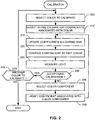
- FIG. 2 is a flowchart of an example process that may, for example, be implemented as instructions carried out by one or more processors to implement the example calibrator 130.
- the example process of FIG. 2 may be embodied in program code and/or computer-readable instructions stored on a tangible machine-readable medium accessible by a processor, a computer and/or other machine having a processor.
- Computer-readable instructions comprise, for example, instructions that cause a processor, a computer and/or a machine having a processor to perform one or more particular processes.
- some or all of the example process may be implemented using any combination of fuses, ASIC(s), PLD(s), FPLD(s), FPGA(s), discrete logic, hardware, firmware, or any combination thereof.
- the example process of FIG. 2 begins with the calibrator 130 selecting a color to calibrate (block 205).
- the calibrator 130 calibrates a white color and, in the example shown in FIG. 5 , the calibrator 130 calibrates the virtual primary color 305 of FIG. 3 .
- the calibrator 130 selects initial calibration coefficients 125 associated with selected color (block 210).
- the calibrator 130 selects initial values for k ww , k rw , k gw , and k bw ; and, for the example of FIG. 5 , the calibrator 130 selects initial values for k gg , k gb and k gr .
- the calibrator 130 selects the initial coefficient values to represent particular default percentages that ensures that each calibrated color includes color emitted by each colored LED of the lighting unit 105.
- the default percentages can be determined experimentally based on color shifts measured for a large number of LEDs and the statistical variances associated with those measurements-the color shifts and associated percentages and variances may vary from LED manufacturer to LED manufacturer.
- the calibrator 130 updates the coefficients 125 in the lighting unit 105 (block 215), and controls the lighting unit 105 to emit the color being calibrated (block 220).
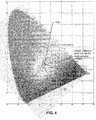
- the light sensor 135 measures the light emitted by the lighting unit 105 (block 225). In the example of FIG. 4 , the light emitted by the lighting unit 105 is directed towards a central target point 405 and in the example of FIG. 5 , the light emitted by the lighting unit 105 is directed toward a primary color target point 505.
- the calibrator 130 selects a first color component to adjust (block 235). In the example of FIG. 4 , the calibrator 130 selects the red component and, in the example of FIG. 5 , selects the blue component.
- the calibrator 130 adjusts the coefficient 125 associated with the selected color component to adjust the emitted light to be closer to the desired color (block 240).
- the coefficient k wr is increased and, in the example of FIG. 5 , the coefficient k gb is increased.
- Control then returns to block 215 to update the lighting unit 105 and re-measure the light being emitted. This process continues until acceptable calibration is achieved (block 230).
- the calibration adaptively spirals toward the desired color 410. The reason for the spiral shape is to provide an organized sequence of operations in order to converge on the desired color point.
- Stepping in smaller and smaller increments (using less and less of each color) in each separate color generates a spiral inward towards the target color and creates a spiral path to the target color point.
- Use of this algorithm removes a need for more complex algorithms or error corrections due to an overshoot.
- the calibration adaptively moves in a winding path.
- the winding path is due to the fact that the system is converging on a point with only two other colors, and so it goes back and forth between the two colors toward the desired color.
- the calibrator 130 determines whether other colors remain to be calibrated (block 245). For example, after calibrating white as shown in FIG. 4 , green may be calibrated as shown in FIG. 5 . If another color need to be calibrated (block 245), control returns to block 205 to calibrate the next color. When all colors have been calibrated (block 245), color exits from the example process of FIG. 2 .
- the lighting unit 105 Once the lighting unit 105 has been calibrated, it can be installed in a vehicle adjacent to other similarly calibrated lighting units. Commands subsequently issued to the lighting units 105 to produce a particular color are interpreted utilizing their respective calibration coefficients 125. Although the LEDs of the lighting units 105 vary, by driving the LED units differently in the different lighting units 105 based on the calibration coefficients 125 stored within the unit, a consistent color and luminosity can be output.
- the embodiments disclosed herein may include a tangible computer-readable storage medium for storing program data, a processor for executing the program data to implement the methods and apparatus disclosed herein, a communications port for handling communications with other devices, and user interface devices such as a display, a keyboard, a mouse, a display, etc.
- these software modules may be stored as program instructions or computer-readable codes, which are executable by the processor, on the tangible computer-readable storage medium.
- tangible computer-readable storage medium and “non-transitory computer-readable storage medium” are defined to expressly exclude propagating signals and to exclude any computer-readable media on which signals may be propagated.
- a computer-readable storage medium may include internal signal traces, cables, wires and/or internal signal paths carrying signals thereon.
- Example tangible and/or non-transitory computer-readable medium may be volatile and/or non-volatile, and may include a memory, a memory device, a compact disc (CD), a digital versatile disc (DVD), a floppy disk, a read-only memory (ROM), a random-access memory (RAM), a programmable ROM (PROM), an electronically-programmable ROM (EPROM), an electronically-erasable PROM (EEPROM), an optical storage device, a magnetic storage device and/or any other device in which information is stored for any duration (e.g., for extended time periods, permanently, during buffering, and/or during caching) and which can be accessed by a processor, a computer and/or other machine having a processor.
- a memory device e.g., a compact disc (CD), a digital versatile disc (DVD), a floppy disk, a read-only memory (ROM), a random-access memory (RAM), a programmable ROM (PROM), an electronically-programmable
- the computer-readable storage medium can also be distributed over network-coupled computer systems (e.g., be a network-attached storage device, a server-based storage device, and/or a shared network storage device) so that computer-readable code may be stored and executed in a distributed fashion.
- network-coupled computer systems e.g., be a network-attached storage device, a server-based storage device, and/or a shared network storage device
- Such a media can be read by a computer, instructions thereon stored in a memory, and executed by a processor.
- Disclosed embodiments may be described in terms of functional block components and various processing steps. Such functional blocks may be realized by any number of hardware and/or software components configured to perform the specified functions. For example, disclosed embodiments may employ various integrated circuit components, e.g., memory elements, processing elements, logic elements, look-up tables, and the like, which may carry out a variety of functions under the control of one or more microprocessors or other control devices. Similarly, where disclosed elements are implemented using software programming, the disclosed software elements may be implemented with any programming or scripting language such as C, C++, Java, assembler, or the like, with the various algorithms being implemented with any combination of data structures, objects, processes, routines or other programming elements. Functional aspects may be implemented in algorithms that execute on one or more processors.
- the disclosed embodiments can employ any number of conventional techniques for electronics configuration, signal processing and/or control, data processing, and the like.
- the words “mechanism” and “element” are used broadly and are not limited to mechanical or physical embodiments, but can include software routines in conjunction with processors, etc.
Landscapes
- Circuit Arrangement For Electric Light Sources In General (AREA)
Description
- A lighting unit may be implemented using a plurality of different colored light sources such as different colored light emitting diodes (LEDs). For example, a lighting unit may include a white LED, a red LED, a blue LED and a green LED. Because of manufacturing process variations, the color emitted by a particular LED may differ from its intended or nominal color. For example, blue LEDs may not all emit the same color or intensity of blue light. Accordingly, different lighting units may emit different colors of light given the same control inputs. For example, when controlled to emit green light, a first lighting unit may emit a blue-tinted green light, while another lighting unit may emit a red-tinted green light. When a plurality of such lighting units is combined to light a space as an airplane cabin, the color of light emitted throughout the cabin may display unacceptable variation in color or intensity.
- Conventional solutions to overcome these problems include the screening of light sources (e.g., LEDs) to reduce variability in emitted light color to acceptable tolerances. However, such screening may result in unacceptable costs and/or manufacturing yields. Another conventional solution calibrates lighting units to achieve color consistency for a small number of fixed colors of light. However, such conventional calibration methods prevent multi-colored lighting units from being used to their fullest potential, and prevent users from creating customized lighting conditions.
-
WO 2007069149 describes a method for calculating a color point for multiple LED light sources using the difference between the color points and corresponding reference color points and adjusting an analog current drive level of the light sources to provide a more accurate way correct for the color changes due to change in drive current, temperature, and aging effects. - Methods, apparatus and articles of manufacture to calibrate lighting units that overcome at least these problems are disclosed herein. In particular, lighting units calibrated and operated according to the examples disclosed herein are able to consistently and reliable generate a gamut of colored light without need to screen light sources.
- According to a first aspect of the present invention there is provided a method for calibrating a color LED light unit as claimed in attached claim 1.
- A non-transitory computer program product is also provided, comprising a computer usable medium having a computer readable program code embodied therein, said computer readable program code adapted to be executed to implement the method described above.
- According to a second aspect of the present invention there is provided a system for calibrating a color LED light unit as claimed in attached claim 11.
- Preferred but not essential features are set out in the attached sub-claims.
- Features and advantages of this disclosure will become apparent by describing in detail exemplary embodiments with reference to the attached drawings in which:
-
FIG. 1 is a schematic illustration of an example apparatus that may be used to calibrate a lighting unit; -
FIG. 2 is a flowchart illustrating an example process that may, for example, be embodied as machine-readable instructions executed by one or more processors to implement the example calibrator ofFIG. 1 ; and -
FIG. 3 is a chromaticity diagram illustrating an example operation of the example apparatus ofFIG. 1 . -
FIG. 4 is a chromaticity diagram illustrating an example operation of the example apparatus ofFIG. 1 in which the apparatus spirals in to a centrally located target point. -
FIG. 5 is a chromaticity diagram illustrating an example operation of the example apparatus ofFIG. 1 in which the apparatus zig-zags towards a primary color point. - Exemplary embodiments will now be described more fully with reference to the accompanying drawings.
-
FIG. 1 is a schematic illustration of anexample apparatus 100 that may be used to calibrate alighting unit 105. To emit multi-colored light, theexample lighting unit 105 ofFIG. 1 includes a plurality of different colored light sources 110-112. Example light sources 110-112 include an LED, an organic light emitting diodes (OLED), or the like. Thus, for instance, thelighting unit 105 may include a white LED, a red LED, a blue LED and a green LED. The white LED is optional, but can be advantageously, included because it has a high color rendering index. Furthermore, the invention is not limited to the use of red, blue, and green LEDs, but rather could incorporate an arbitrary first color, second color, and third color LED. Other numbers and/or color combinations of light sources may be used. - To generate different colors of emitted light, the
lighting unit 105 includes acontroller 115. Based oncolor control information 120, theexample controller 115 turns on a corresponding combination of the LEDs 110-112 at respective intensities. In disclosed embodiments, the desiredcolor control information 120 represents absolute or relative amounts of white (W), red (R), blue (B), and green (G). For example, if purple light is desired, thecolor control information 120 may represent equal amounts of red and blue, with the amount of blue and red reflecting the desired color saturation. - The LEDs and associated measurement sensor(s) 135 may be included in a calibration chamber that shields the measurement system from external light or other noise. The chamber can provide the LEDs at predefined distances from the sensor(s) 135 and may also shield the sensors from direct input from the LEDs (e.g., through translucent or opaque (for indirect lighting) filters).
- The
controller 115 may determine which of the LEDs 110-112 to turn on and at what intensities based on the following mathematical equations:


kww krw krr krb Krg kbw kbr kbb kbg kgw kgr kgb kgg calibration coefficients 125 determined by acalibrator 130; - W, R, B and G collectively represent the desired
color 120 to be emitted; and - F(W), F(R), F(B) and F(G) represent the light intensity to be emitted by a white LED, a red LED, a blue LED and a green LED, respectively.
- The
calibration coefficients 125 represent the inter-dependence of the various colored LEDs in generating a particular desiredcolor 120, and enable the use of one or more colored LEDs to compensate for a shift in color of another colored LED. For example, if a pure green color is desired (e.g., R=B=0), the expressions of Eqs. (1)-(4) also result in the blue LED and the red LEDs being turn on, according the values of kbg and krg, respectively. In this example, turning on of the red LED and the blue LED, in addition to the green LED, compensates for the color shift of the green LED. Thelighting unit 105 includes any type of non-volatile memory (not shown) to store thecalibration coefficients 125. - The
example calibrator 130 ofFIG. 1 determines for eachparticular lighting unit 105 the set ofcalibration coefficients 125 that calibrates thatlighting unit 105 such that thelighting unit 105 emits substantially the same colored light asother lighting units 105 in response to identicalcolor control information 120. Because the LEDs 110-112 indifferent lighting units 105 may have different color shifts, thecalibrator 130 may compute a different set ofcalibration coefficients 125 for eachlighting unit 105. - The
calibrator 130 computes thecalibration coefficients 125 during manufacturing and/or testing of thelighting unit 105, and stores thecalibration coefficients 125 in thelighting unit 105 for subsequent use by thecontroller 115, as described above. Thecalibrator 130 may also compute and/or update thecalibration coefficients 125 in situ when an LED 110-112 is replaced or to compensate for color shifts that may arise over time due to, for example, component aging. An example process that may be carried out by thecalibrator 130 to compute thecalibration coefficients 125 is described below in connection withFIG. 2 . -
FIG. 3 is a chromaticity diagram representing a gamut of colors that can be generated by thelighting unit 105. Worst case LED color shifts can be based on measured maximum variance values. Considering these worst case LED color shifts, a consistently realizable color gamut (depicted astriangle 305 inFIG. 3 ) can be determined, at least within predefined probabilities (e.g., p=98%, p=99.5%, p=99.99%, which would reflect the probability that any particular manufactured light unit could realize this color gamut). Therealizable color gamut 305 represents the color gamut that everylighting unit 105 of a particular design can achieve regardless of the particular color shifts of any of the unit's LEDs 110-112. In other words, therealizable color gamut 305 is a color gamut that can be consistently achieved (and, thus, guaranteed) acrosslighting units 105. Vertices of thetriangle 305 represent virtual primary colors. For example, the color corresponding to avertex 310 would be generated in response to a request for a fully saturated primary green color. Because the vertices of thetriangle 305 are different from the primary colors, each color in the color gamut contained inside thetriangle 305 contains at least some red, green and blue. - Accordingly, the
calibrator 130 selects thecoefficients 125 such that for any color supported by the lighting unit 105 (i.e., any color inside the triangle 305), thelighting unit 105 always emits at least some red light, some green light and some blue light. That is, thecalibrator 130 is configured to ensure that none of thecoefficients 125 have a value of zero. By ensuring that at least some of all three colors are emitted, thecalibrator 130 ensures that the light emitted by thelighting units 105 has consistent rendering and reflections and, thus, is perceived by humans as being consistent fromlighting unit 105 tolighting unit 105. Thecolor gamut 305 can be determined experimentally based on color shifts measured for a large number of LEDs. This number should be large enough so that statistically significant determinations of variance and overall population characteristics can be made with a predefined degree of certainty. - To measure or sense the color and intensity of light emitted by the
lighting unit 105, theapparatus 100 includes any number and/or type(s) of light sensor(s), one of which is designated atreference numeral 135. Thelight sensor 135 provides one ormore values 140 representative of the color and intensity of light emitted by thelighting unit 105 to thecalibrator 130 for use in computing thecalibration coefficients 125. - In an embodiment, the
controller 115 adjusts the brightness of the LEDs 110-112 using pulse-width modulation (PWM) with 1024 different modulation duty cycles, which can be represented by 10 bits, and 7-bit calibration coefficients 125. However, other resolutions (e.g., 8, 16, 24 bits, and floating point numbers, etc.) may be used to represent modulation duty cycles and/or coefficients. Because in Eqs. (1) - (4) the various contributing colors are multiplied by their associatedcoefficient 125, colors remain proportional, which ensures that resultant colors of the emitted light are independent of flux. As with any calibration method, there is a resolution limit and color contributions become negligible or disappear altogether as the requested brightness approaches zero, due to truncation. In real-life situations, such effects are normally not humanly perceptible and are inherent in any digital system. If a higher resolution is required, a lower starting value for white can be selected (e.g., 80% versus 90%), which will add one bit of effective resolution, but may degrade color rendering. - The
calibrator 130 may be implemented by computer(s) or machine(s) having a processor, circuit(s), programmable processor(s), fuses, application-specific integrated circuit(s) (ASIC(s)), programmable logic device(s) (PLD(s)), field-programmable logic device(s) (FPLD(s)), field-programmable gate array(s) (FPGA(s)), etc. When any embodiment of this disclosure is interpreted to cover a purely software and/or firmware implementation, at least one of theweather data servers -
FIG. 2 is a flowchart of an example process that may, for example, be implemented as instructions carried out by one or more processors to implement theexample calibrator 130. The example process ofFIG. 2 may be embodied in program code and/or computer-readable instructions stored on a tangible machine-readable medium accessible by a processor, a computer and/or other machine having a processor. Computer-readable instructions comprise, for example, instructions that cause a processor, a computer and/or a machine having a processor to perform one or more particular processes. Alternatively, some or all of the example process may be implemented using any combination of fuses, ASIC(s), PLD(s), FPLD(s), FPGA(s), discrete logic, hardware, firmware, or any combination thereof. - The example process of
FIG. 2 begins with thecalibrator 130 selecting a color to calibrate (block 205). In an example shown inFIG. 4 , thecalibrator 130 calibrates a white color and, in the example shown inFIG. 5 , thecalibrator 130 calibrates the virtualprimary color 305 ofFIG. 3 . Thecalibrator 130 selectsinitial calibration coefficients 125 associated with selected color (block 210). For the example ofFIG. 4 , thecalibrator 130 selects initial values for kww, krw, kgw, and kbw; and, for the example ofFIG. 5 , thecalibrator 130 selects initial values for kgg, kgb and kgr. Thecalibrator 130 selects the initial coefficient values to represent particular default percentages that ensures that each calibrated color includes color emitted by each colored LED of thelighting unit 105. The default percentages can be determined experimentally based on color shifts measured for a large number of LEDs and the statistical variances associated with those measurements-the color shifts and associated percentages and variances may vary from LED manufacturer to LED manufacturer. - The
calibrator 130 updates thecoefficients 125 in the lighting unit 105 (block 215), and controls thelighting unit 105 to emit the color being calibrated (block 220). Thelight sensor 135 measures the light emitted by the lighting unit 105 (block 225). In the example ofFIG. 4 , the light emitted by thelighting unit 105 is directed towards acentral target point 405 and in the example ofFIG. 5 , the light emitted by thelighting unit 105 is directed toward a primarycolor target point 505. - If the light currently being emitted by the
lighting unit 105 is not suitably close (suitably close being defined by some relatively objective criteria, e.g., based on the limits of human visual perception, and possibly defined in terms of MacAdam Ellipses or other form of objective measurement) to the desired color (block 230), thecalibrator 130 selects a first color component to adjust (block 235). In the example ofFIG. 4 , thecalibrator 130 selects the red component and, in the example ofFIG. 5 , selects the blue component. - The
calibrator 130 adjusts the coefficient 125 associated with the selected color component to adjust the emitted light to be closer to the desired color (block 240). In the example ofFIG. 4 , the coefficient kwr is increased and, in the example ofFIG. 5 , the coefficient kgb is increased. Control then returns to block 215 to update thelighting unit 105 and re-measure the light being emitted. This process continues until acceptable calibration is achieved (block 230). As shown inFIG. 4 , the calibration adaptively spirals toward the desiredcolor 410. The reason for the spiral shape is to provide an organized sequence of operations in order to converge on the desired color point. Stepping in smaller and smaller increments (using less and less of each color) in each separate color generates a spiral inward towards the target color and creates a spiral path to the target color point. Use of this algorithm removes a need for more complex algorithms or error corrections due to an overshoot. - In
FIG. 5 , the calibration adaptively moves in a winding path. The winding path is due to the fact that the system is converging on a point with only two other colors, and so it goes back and forth between the two colors toward the desired color. - When acceptable calibration for the selected color is achieved (block 230), the
calibrator 130 determines whether other colors remain to be calibrated (block 245). For example, after calibrating white as shown inFIG. 4 , green may be calibrated as shown inFIG. 5 . If another color need to be calibrated (block 245), control returns to block 205 to calibrate the next color. When all colors have been calibrated (block 245), color exits from the example process ofFIG. 2 . - Once the
lighting unit 105 has been calibrated, it can be installed in a vehicle adjacent to other similarly calibrated lighting units. Commands subsequently issued to thelighting units 105 to produce a particular color are interpreted utilizing theirrespective calibration coefficients 125. Although the LEDs of thelighting units 105 vary, by driving the LED units differently in thedifferent lighting units 105 based on thecalibration coefficients 125 stored within the unit, a consistent color and luminosity can be output. - The embodiments disclosed herein may include a tangible computer-readable storage medium for storing program data, a processor for executing the program data to implement the methods and apparatus disclosed herein, a communications port for handling communications with other devices, and user interface devices such as a display, a keyboard, a mouse, a display, etc. When software modules are involved, these software modules may be stored as program instructions or computer-readable codes, which are executable by the processor, on the tangible computer-readable storage medium.
- As used herein, the terms "tangible computer-readable storage medium" and "non-transitory computer-readable storage medium" are defined to expressly exclude propagating signals and to exclude any computer-readable media on which signals may be propagated. However, a computer-readable storage medium may include internal signal traces, cables, wires and/or internal signal paths carrying signals thereon. Example tangible and/or non-transitory computer-readable medium may be volatile and/or non-volatile, and may include a memory, a memory device, a compact disc (CD), a digital versatile disc (DVD), a floppy disk, a read-only memory (ROM), a random-access memory (RAM), a programmable ROM (PROM), an electronically-programmable ROM (EPROM), an electronically-erasable PROM (EEPROM), an optical storage device, a magnetic storage device and/or any other device in which information is stored for any duration (e.g., for extended time periods, permanently, during buffering, and/or during caching) and which can be accessed by a processor, a computer and/or other machine having a processor. The computer-readable storage medium can also be distributed over network-coupled computer systems (e.g., be a network-attached storage device, a server-based storage device, and/or a shared network storage device) so that computer-readable code may be stored and executed in a distributed fashion. Such a media can be read by a computer, instructions thereon stored in a memory, and executed by a processor.
- Disclosed embodiments may be described in terms of functional block components and various processing steps. Such functional blocks may be realized by any number of hardware and/or software components configured to perform the specified functions. For example, disclosed embodiments may employ various integrated circuit components, e.g., memory elements, processing elements, logic elements, look-up tables, and the like, which may carry out a variety of functions under the control of one or more microprocessors or other control devices. Similarly, where disclosed elements are implemented using software programming, the disclosed software elements may be implemented with any programming or scripting language such as C, C++, Java, assembler, or the like, with the various algorithms being implemented with any combination of data structures, objects, processes, routines or other programming elements. Functional aspects may be implemented in algorithms that execute on one or more processors. Furthermore, the disclosed embodiments can employ any number of conventional techniques for electronics configuration, signal processing and/or control, data processing, and the like. The words "mechanism" and "element" are used broadly and are not limited to mechanical or physical embodiments, but can include software routines in conjunction with processors, etc.
Claims (11)
- A method for calibrating a color LED light unit (105) comprising at least first-(110), second- (111), and third- (112) color LEDs, comprising:a) defining a target color on a color map to calibrate (205);b) selecting initial calibration coefficients associated with the target color (210);c) storing the initial or updated calibration coefficients in a non-volatile memory of the light unit (215);d) controlling the light unit to drive the LEDs to attempt to emit the target color, producing an attempted color, utilizing the calibration coefficients (220);e) measuring (135) the attempted color to determine if it matches the target color within a predefined tolerance (225);f) if the attempted color matches the target color (230:Yes), then terminating the method (245:No);g) if the attempted color does not match the target color (230:No), then performing the following:wherein the first color is red (R), the second color is blue (B), and the third color is green (G),h) selecting a color component (235);i) updating at least one calibration coefficient associated with the selected color component (240); andj) performing (c)-(i) again.
wherein the LED light unit further comprises a white (W) LED, characterized in that the controller determines which of the LEDs to turn on and at what intensities based on the following mathematical equations:



kww krw krr krb krg kbw kbr kbb kbg kgw kgr kgb kgg are calibration coefficients determined by a calibrator and represent default percentages for ensuring that each calibrated color includes color emitted by each colored LED in generating a particular desired color;W, R, B and G collectively represent the desired color to be emitted; andF(W), F(R), F(B) and F(G) represent the light intensity to be emitted by a white LED, a red LED, a blue LED and a green LED, respectively. - The method according to claim 1, wherein the controlling of the light unit is performed using variations in a pulse width in a pulse-width-modulated (PWM) signal.
- The method according to claim 2, wherein the variations comprise at least 1024 different values.
- The method according to claim 1, wherein the calibration coefficients are represented by 7-, 8-, 16-, or 24-bit values.
- The method according to claim 1, wherein the determining a color match comprises:matching to a predefined multiplier of a MacAdam Ellipse.
- The method according to claim 1, further comprising:performing (a)-(j) for one or more additional target colors.
- The method according to claim 6, wherein at least three colors are used as target colors, and the three colors define a color gamut as three points of vertices of a triangle.
- The method according to claim 7, further comprising:measuring a statistically significant plurality of each color class LED;determining a variance for each color class LED;defining a realizable color gamut within a predetermined probability; anddefined the tree points to specifically bound the worst case color gamut.
- The method according to claim 8, wherein the vertices represent virtual primary colors.
- The method according to claim 9, wherein the vertices require driving of the red, green, and blue LEDs with non-zero values.
- A system for calibrating a color LED light unit (105), wherein:the color LED light unit comprises:at least first- (110), second- (111), and third- (112) color LEDs; anda non-volatile memory; andthe system comprises:a) a target defining unit that defines a target color on a color map to calibrate 115, 205);b) an assigning unit that selects initial calibration coefficients (115, 210) associated with the target color and stores the initial or updated calibration coefficients in the non-volatile memory (115,215);c) a controller that controls the light unit to drive the LEDs to attempt to emit the target color, producing an attempted color, utilizing the calibration coefficients (115, 220);d) a sensor (135) that measures the attempted color to determine if it matches the target color within a predefined tolerance (225); ande) a selection and adaption unit (115) configured such that:f) if the attempted color matches the target color (230:Yes), then the system ceases performing calibration (245:No);g) if the attempted color does not match the target color (230:No), then a selection unit selects a color component (235), and an adaption unit updates at least one calibration coefficient associated with the selected color component (240).wherein the first color is red (R), the second color is blue (B), and the third color is green (G),wherein the LED light unit further comprises a white (W) LED,characterized in that the controller determines which of the LEDs to turn on and at what intensities based on the following mathematical equations:


kww Krw krr krb krg kbw kbr kbb kbg kgw kgr kgb kgg are calibration coefficients determined by a calibrator and represent default percentages for ensuring that each calibrated color includes color emitted by each coloured LED in generating a particular desired color;W, R, B and G collectively represent the desired color to be emitted; andF(W), F(R), F(B) and F(G) represent the light intensity to be emitted by a white LED, a red LED, a blue LED and a green LED, respectively.
Applications Claiming Priority (2)
| Application Number | Priority Date | Filing Date | Title |
|---|---|---|---|
| US201161546259P | 2011-10-12 | 2011-10-12 | |
| PCT/US2012/059900 WO2013056012A1 (en) | 2011-10-12 | 2012-10-12 | Methods, apparatus and articles of manufacture to calibrate lighting units |
Publications (3)
| Publication Number | Publication Date |
|---|---|
| EP2767144A1 EP2767144A1 (en) | 2014-08-20 |
| EP2767144A4 EP2767144A4 (en) | 2015-08-12 |
| EP2767144B1 true EP2767144B1 (en) | 2017-01-11 |
Family
ID=48082475
Family Applications (1)
| Application Number | Title | Priority Date | Filing Date |
|---|---|---|---|
| EP12840208.8A Not-in-force EP2767144B1 (en) | 2011-10-12 | 2012-10-12 | Methods, apparatus and articles of manufacture to calibrate lighting units |
Country Status (3)
| Country | Link |
|---|---|
| US (2) | US9018853B2 (en) |
| EP (1) | EP2767144B1 (en) |
| WO (1) | WO2013056012A1 (en) |
Families Citing this family (22)
| Publication number | Priority date | Publication date | Assignee | Title |
|---|---|---|---|---|
| US20160053977A1 (en) | 2008-09-24 | 2016-02-25 | B/E Aerospace, Inc. | Flexible led lighting element |
| WO2013056012A1 (en) * | 2011-10-12 | 2013-04-18 | B/E Aerospace, Inc. | Methods, apparatus and articles of manufacture to calibrate lighting units |
| GB2525167A (en) * | 2014-03-14 | 2015-10-21 | Saf T Glo Ltd | Lighting systems |
| CN106660638A (en) | 2014-03-14 | 2017-05-10 | 萨夫-T-格罗有限公司 | Lighting system |
| US9338851B2 (en) * | 2014-04-10 | 2016-05-10 | Institut National D'optique | Operation of a LED lighting system at a target output color using a color sensor |
| CN103945588B (en) * | 2014-05-12 | 2016-05-04 | 福州大学 | The even light-dimming method of a kind of large-area OLEDs module |
| US10123005B2 (en) * | 2015-03-06 | 2018-11-06 | Apple Inc. | Displays with unit-specific display identification data |
| EP3072742B1 (en) * | 2015-03-26 | 2020-03-18 | Goodrich Lighting Systems GmbH | Interior aircraft led light unit and method of calibrating an interior aircraft led light unit |
| EP3289283B1 (en) * | 2015-04-27 | 2022-11-02 | B/E Aerospace, Inc. | Flexible led lighting element |
| DE102015115474B4 (en) * | 2015-09-14 | 2025-08-21 | Deutsche Telekom Ag | Method for calibrating a light-opaque display |
| EP3360392B1 (en) * | 2015-10-07 | 2020-02-26 | B/E Aerospace, Inc. | Flexible led lighting element |
| US10127749B2 (en) * | 2016-01-11 | 2018-11-13 | Ford Global Technologies, Llc | System and method for profile indication on a key fob |
| EP3590307B1 (en) | 2017-02-28 | 2023-09-27 | Quarkstar LLC | Lifetime color stabilization of color-shifting artificial light sources |
| CN108426186B (en) * | 2018-03-14 | 2020-05-22 | 调调(北京)科技有限公司 | Lamp color calibration method and device and electronic equipment |
| US10531532B1 (en) * | 2018-07-10 | 2020-01-07 | Eaton Intelligent Power Limited | Setting current error reduction for light-emitting diode driver circuits |
| EP3911124B1 (en) * | 2020-05-13 | 2024-05-01 | Harman Professional Denmark ApS | Color control in subtractive color mixing system |
| CN112272430B (en) * | 2020-10-10 | 2023-03-31 | 广州市雅江光电设备有限公司 | Automatic correction system and method for color lamps |
| FR3115859B1 (en) | 2020-10-30 | 2025-08-01 | Valeo Vision | Method of operating an automotive lighting device and automotive lighting device |
| CN113573445B (en) * | 2021-07-23 | 2023-06-27 | 北京字节跳动网络技术有限公司 | Determination method and device for lamp driving parameters and electronic equipment |
| US11490484B1 (en) | 2021-10-15 | 2022-11-01 | Aircraft Lighting International Inc. | Retrofit light-emitting diode lamp and circuit thereof |
| IT202200007916A1 (en) * | 2022-04-21 | 2023-10-21 | Clay Paky S R L | Procedure for the detection and processing of photometric parameters of corresponding lighting devices, IT products and controllers |
| CN115901195A (en) * | 2022-11-29 | 2023-04-04 | 德丰电创科技股份有限公司 | A multi-region high-precision color brightness calibration method and system for automotive ambient lights |
Family Cites Families (80)
| Publication number | Priority date | Publication date | Assignee | Title |
|---|---|---|---|---|
| US4729742A (en) | 1984-01-25 | 1988-03-08 | Matsushita Electric Works, Ltd. | Electric power distribution track |
| US5003432A (en) | 1988-05-09 | 1991-03-26 | Mandy Robert R | Down lighting systems and fixtures therefor |
| FR2697484B1 (en) | 1992-11-02 | 1995-01-20 | Valeo Vision | Modular element for the production of traffic lights for motor vehicles. |
| GB2293443B (en) | 1994-08-04 | 1998-02-18 | British Airways Plc | A lighting system for an aircraft cabin |
| US6211626B1 (en) | 1997-08-26 | 2001-04-03 | Color Kinetics, Incorporated | Illumination components |
| US6016038A (en) | 1997-08-26 | 2000-01-18 | Color Kinetics, Inc. | Multicolored LED lighting method and apparatus |
| US6220721B1 (en) | 1998-04-28 | 2001-04-24 | Genlyte Thomas Group Llc | Multi-lyte channel lighting system |
| US6249913B1 (en) | 1998-10-09 | 2001-06-19 | General Dynamics Ots (Aerospace), Inc. | Aircraft data management system |
| IL151435A0 (en) | 2000-02-23 | 2003-04-10 | Production Solutions Inc | Sequential control circuit |
| CN1165183C (en) * | 2000-05-15 | 2004-09-01 | 北京北达华彩科技有限公司 | Adaptive chroma compensation method and compensator |
| US7202613B2 (en) | 2001-05-30 | 2007-04-10 | Color Kinetics Incorporated | Controlled lighting methods and apparatus |
| US7161556B2 (en) | 2000-08-07 | 2007-01-09 | Color Kinetics Incorporated | Systems and methods for programming illumination devices |
| US6441558B1 (en) * | 2000-12-07 | 2002-08-27 | Koninklijke Philips Electronics N.V. | White LED luminary light control system |
| JP4652691B2 (en) | 2002-02-06 | 2011-03-16 | フィリップス ソリッド−ステート ライティング ソリューションズ インコーポレイテッド | Method and apparatus for controlled light emission |
| JP2004158370A (en) | 2002-11-08 | 2004-06-03 | Hakko Automation Kk | Lighting system |
| US7114827B2 (en) | 2003-03-17 | 2006-10-03 | Syair Designs Llc | Lighting assembly |
| US7018075B2 (en) | 2003-05-02 | 2006-03-28 | Rodgers Holdings | Protective overhead light fixture kit |
| US8120812B2 (en) * | 2003-08-14 | 2012-02-21 | Xerox Corporation | System and method for obtaining color consistency for a color print job across multiple output devices |
| US7198387B1 (en) | 2003-12-18 | 2007-04-03 | B/E Aerospace, Inc. | Light fixture for an LED-based aircraft lighting system |
| US7365720B2 (en) | 2003-12-23 | 2008-04-29 | Barco N.V. | Colour calibration of emissive display devices |
| EP1711739A4 (en) | 2004-01-28 | 2008-07-23 | Tir Technology Lp | LUMINAIRE DIRECTLY VISIBLE |
| US7342513B2 (en) | 2004-02-13 | 2008-03-11 | Goodrich Lighting Systems, Inc. | Aircraft interior wireless communications system |
| JP2005249873A (en) | 2004-03-01 | 2005-09-15 | Canon Inc | Image forming apparatus and image stabilization processing execution method |
| US7515128B2 (en) * | 2004-03-15 | 2009-04-07 | Philips Solid-State Lighting Solutions, Inc. | Methods and apparatus for providing luminance compensation |
| US7218358B2 (en) | 2004-06-15 | 2007-05-15 | Coretronic Corporation | Method and apparatus for calibrating color temperature of color display devices |
| US7173383B2 (en) * | 2004-09-08 | 2007-02-06 | Emteq, Inc. | Lighting apparatus having a plurality of independently controlled sources of different colors of light |
| WO2006083934A2 (en) | 2005-02-01 | 2006-08-10 | B/E Aerospace, Inc. | Lighting system and method and apparatus for adjusting same |
| EP1865564B1 (en) | 2005-03-18 | 2014-11-19 | Mitsubishi Chemical Corporation | Light-emitting device, white light-emitting device, illuminator, and image display |
| US7375476B2 (en) * | 2005-04-08 | 2008-05-20 | S.C. Johnson & Son, Inc. | Lighting device having a circuit including a plurality of light emitting diodes, and methods of controlling and calibrating lighting devices |
| DE102005022832A1 (en) * | 2005-05-11 | 2006-11-16 | Arnold & Richter Cine Technik Gmbh & Co. Betriebs Kg | Headlamp for film and video recordings |
| US7443104B2 (en) * | 2005-07-27 | 2008-10-28 | Osram Opto Semiconductors Gmbh | Lighting apparatus and method for controlling brightness and color location thereof |
| US7230222B2 (en) | 2005-08-15 | 2007-06-12 | Avago Technologies Ecbu Ip (Singapore) Pte. Ltd. | Calibrated LED light module |
| JP4517999B2 (en) | 2005-10-14 | 2010-08-04 | 東芝ライテック株式会社 | Light control device unit and light control system |
| US7303301B2 (en) | 2005-11-01 | 2007-12-04 | Nexxus Lighting, Inc. | Submersible LED light fixture |
| EP2597517A2 (en) | 2005-11-08 | 2013-05-29 | Garrett J Young | Apparatus, methods, and systems for multi-primary display or projection |
| US20070139941A1 (en) | 2005-11-16 | 2007-06-21 | Bryan Eric A | Ceiling illumination for aircraft interiors |
| JP5249773B2 (en) * | 2005-11-18 | 2013-07-31 | クリー インコーポレイテッド | Solid state lighting panel with variable voltage boost current source |
| EP1958483B1 (en) * | 2005-12-01 | 2012-06-13 | Martin Professional A/S | Method and apparatus for controlling a variable-colour light source |
| JP2009519579A (en) * | 2005-12-16 | 2009-05-14 | コーニンクレッカ フィリップス エレクトロニクス エヌ ヴィ | Illumination device and method for controlling the illumination device |
| EP1979726B1 (en) * | 2006-01-19 | 2013-11-06 | Philips Intellectual Property & Standards GmbH | Color-controlled illumination device |
| JP4445937B2 (en) | 2006-03-16 | 2010-04-07 | 日本電信電話株式会社 | Environmental control system and environmental control method |
| US7821194B2 (en) * | 2006-04-18 | 2010-10-26 | Cree, Inc. | Solid state lighting devices including light mixtures |
| US7658506B2 (en) | 2006-05-12 | 2010-02-09 | Philips Solid-State Lighting Solutions, Inc. | Recessed cove lighting apparatus for architectural surfaces |
| US7696964B2 (en) * | 2006-06-09 | 2010-04-13 | Philips Lumileds Lighting Company, Llc | LED backlight for LCD with color uniformity recalibration over lifetime |
| US20080062070A1 (en) | 2006-09-13 | 2008-03-13 | Honeywell International Inc. | Led brightness compensation system and method |
| US20080089071A1 (en) | 2006-10-12 | 2008-04-17 | Chin-Wen Wang | Lamp structure with adjustable projection angle |
| WO2008047335A1 (en) | 2006-10-19 | 2008-04-24 | Nualight Limited | Improvements in display case luminaires |
| JP4720716B2 (en) | 2006-10-26 | 2011-07-13 | パナソニック電工株式会社 | Load control system |
| JP4650404B2 (en) | 2006-11-27 | 2011-03-16 | パナソニック電工株式会社 | Dimming system and dimming controller used therefor |
| RU2470496C2 (en) | 2006-12-11 | 2012-12-20 | Конинклейке Филипс Электроникс Н.В. | System and method of control over illuminators |
| WO2008070981A1 (en) | 2006-12-12 | 2008-06-19 | Tir Technology Lp | System and method for controlling lighting |
| US7766521B2 (en) | 2007-04-27 | 2010-08-03 | The Boeing Company | Aircraft interior sidewall paneling systems provide enhanced cabin lighting and ventilation |
| US7717593B2 (en) | 2007-06-08 | 2010-05-18 | The Boeing Company | Device for improved illumination efficiency |
| US7717594B2 (en) | 2007-06-14 | 2010-05-18 | The Boeing Company | Compact illumination device |
| US8044899B2 (en) | 2007-06-27 | 2011-10-25 | Hong Kong Applied Science and Technology Research Institute Company Limited | Methods and apparatus for backlight calibration |
| US20100188024A1 (en) * | 2007-07-31 | 2010-07-29 | Koninklijke Philips Electronics N.V. | Method of calibrating a lighting system, and lighting system |
| US7857484B2 (en) | 2007-08-31 | 2010-12-28 | The Boeing Company | Lighting panels including embedded illumination devices and methods of making such panels |
| US8177389B1 (en) | 2007-09-13 | 2012-05-15 | Cypress Semiconductor Corporation | Deterministically calculating dimming values for four or more light sources |
| US8264448B2 (en) * | 2007-09-21 | 2012-09-11 | Point Somee Limited Liability Company | Regulation of wavelength shift and perceived color of solid state lighting with temperature variation |
| US7718942B2 (en) * | 2007-10-09 | 2010-05-18 | Avago Technologies Ecbu Ip (Singapore) Pte. Ltd. | Illumination and color management system |
| DE102008029191A1 (en) * | 2008-01-31 | 2009-08-06 | Osram Opto Semiconductors Gmbh | Illumination device for backlighting a display and a display with such a lighting device |
| NZ588390A (en) | 2008-04-04 | 2013-07-26 | Cree Inc | Lamp using a one piece extrusion to mount LEDs on one side and cooling the LEDs using fins on the other side of the extrusion |
| TW201004477A (en) * | 2008-06-10 | 2010-01-16 | Microsemi Corp Analog Mixed Si | Color manager for backlight systems operative at multiple current levels |
| US20100007588A1 (en) | 2008-07-09 | 2010-01-14 | Adaptive Micro Systems Llc | System and method for led degradation and temperature compensation |
| US8471496B2 (en) * | 2008-09-05 | 2013-06-25 | Ketra, Inc. | LED calibration systems and related methods |
| EP2329186B1 (en) * | 2008-09-24 | 2018-02-21 | B/E Aerospace Inc. | An aircraft led washlight system and method for controlling same |
| US8324830B2 (en) * | 2009-02-19 | 2012-12-04 | Microsemi Corp.—Analog Mixed Signal Group Ltd. | Color management for field-sequential LCD display |
| EP2230885B1 (en) * | 2009-03-12 | 2010-11-10 | Infineon Technologies Austria AG | Sigma delta current source and LED driver |
| US8598793B2 (en) * | 2011-05-12 | 2013-12-03 | Ledengin, Inc. | Tuning of emitter with multiple LEDs to a single color bin |
| US8796948B2 (en) * | 2009-11-10 | 2014-08-05 | Lumenetix, Inc. | Lamp color matching and control systems and methods |
| WO2011106623A1 (en) * | 2010-02-25 | 2011-09-01 | B/E Aerospace, Inc | An aircraft led washlight system and method for controlling same |
| WO2011106661A1 (en) * | 2010-02-25 | 2011-09-01 | B/E Aerospace, Inc. | Calibration method for led lighting systems |
| US8723450B2 (en) * | 2011-01-12 | 2014-05-13 | Electronics Theatre Controls, Inc. | System and method for controlling the spectral content of an output of a light fixture |
| US8901850B2 (en) * | 2012-05-06 | 2014-12-02 | Lighting Science Group Corporation | Adaptive anti-glare light system and associated methods |
| US8928249B2 (en) * | 2011-08-25 | 2015-01-06 | Abl Ip Holding Llc | Reducing lumen variability over a range of color temperatures of an output of tunable-white LED lighting devices |
| EP2575411B1 (en) * | 2011-09-27 | 2018-07-25 | Infineon Technologies AG | LED driver with compensation of thermally induced colour drift |
| WO2013056012A1 (en) * | 2011-10-12 | 2013-04-18 | B/E Aerospace, Inc. | Methods, apparatus and articles of manufacture to calibrate lighting units |
| CN103931169B (en) * | 2011-10-17 | 2018-02-02 | 刘世昌 | Universal color gamut mapping and color management method |
| US9039746B2 (en) * | 2013-02-08 | 2015-05-26 | Cree, Inc. | Solid state light emitting devices including adjustable melatonin suppression effects |
| US9013467B2 (en) * | 2013-07-19 | 2015-04-21 | Institut National D'optique | Controlled operation of a LED lighting system at a target output color |
-
2012
- 2012-10-12 WO PCT/US2012/059900 patent/WO2013056012A1/en not_active Ceased
- 2012-10-12 EP EP12840208.8A patent/EP2767144B1/en not_active Not-in-force
- 2012-10-12 US US13/650,289 patent/US9018853B2/en not_active Expired - Fee Related
-
2015
- 2015-04-27 US US14/697,273 patent/US9414459B2/en not_active Expired - Fee Related
Non-Patent Citations (1)
| Title |
|---|
| None * |
Also Published As
| Publication number | Publication date |
|---|---|
| US20130038241A1 (en) | 2013-02-14 |
| US9414459B2 (en) | 2016-08-09 |
| US20150230315A1 (en) | 2015-08-13 |
| EP2767144A4 (en) | 2015-08-12 |
| WO2013056012A1 (en) | 2013-04-18 |
| US9018853B2 (en) | 2015-04-28 |
| EP2767144A1 (en) | 2014-08-20 |
Similar Documents
| Publication | Publication Date | Title |
|---|---|---|
| US9018853B2 (en) | Methods, apparatus and articles of manufacture to calibrate lighting units | |
| EP1958483B1 (en) | Method and apparatus for controlling a variable-colour light source | |
| US9338851B2 (en) | Operation of a LED lighting system at a target output color using a color sensor | |
| KR100741024B1 (en) | Aging compensation method for liquid crystal display device, aging compensation apparatus for liquid crystal display device, recorded medium recording computer program, and liquid crystal display device | |
| US20080297066A1 (en) | Illumination Device and Method for Controlling an Illumination Device | |
| JP2011523759A (en) | Apparatus and method for controlling the color point of an LED light source | |
| US20110241552A1 (en) | Method for maximizing the performance of a luminaire | |
| US9659521B2 (en) | Color control method | |
| US10492256B2 (en) | Method and device for calibrating LED lighting | |
| US20170027037A1 (en) | Methods of controlling rgbw lamps, rgbw lamps and controller therefor | |
| WO2009016567A2 (en) | Method of calibrating a lighting system, and lighting system | |
| US20130093335A1 (en) | A color tunable lamp including a control device with a relative flux sensor | |
| KR20210039822A (en) | Display apparatus and the control method thereof | |
| US20080180670A1 (en) | Lighting device and method for realizing a desired color mixture | |
| EP1961270A1 (en) | Device for determining characteristics of a lighting unit | |
| CA2848855C (en) | Operation of a led lighting system at a target output color using a color sensor | |
| WO2015074695A1 (en) | Method for controlling an illumination system | |
| KR102848001B1 (en) | Optoelectronic modules and methods for producing optoelectronic modules | |
| US12499804B2 (en) | Light measuring apparatus, light measuring system, light measurement method, display adjustment system, and adjustment method | |
| JP2019179651A (en) | Derivation method for optical characteristics of illumination device, control method for illumination device, program, illumination device and illumination controller | |
| US11723126B2 (en) | Control module for controlling a luminaire | |
| JP2018190619A (en) | Lighting control device and lighting control system | |
| WO2024058139A1 (en) | Method for manufacturing illumination device, and illumination system | |
| Nimz et al. | LED application specific calibration method for color measurements | |
| JP2017228547A (en) | Lighting system |
Legal Events
| Date | Code | Title | Description |
|---|---|---|---|
| PUAI | Public reference made under article 153(3) epc to a published international application that has entered the european phase |
Free format text: ORIGINAL CODE: 0009012 |
|
| 17P | Request for examination filed |
Effective date: 20140502 |
|
| AK | Designated contracting states |
Kind code of ref document: A1 Designated state(s): AL AT BE BG CH CY CZ DE DK EE ES FI FR GB GR HR HU IE IS IT LI LT LU LV MC MK MT NL NO PL PT RO RS SE SI SK SM TR |
|
| DAX | Request for extension of the european patent (deleted) | ||
| REG | Reference to a national code |
Ref country code: DE Ref legal event code: R079 Ref document number: 602012027847 Country of ref document: DE Free format text: PREVIOUS MAIN CLASS: H05B0037020000 Ipc: H05B0033080000 |
|
| RA4 | Supplementary search report drawn up and despatched (corrected) |
Effective date: 20150715 |
|
| RIC1 | Information provided on ipc code assigned before grant |
Ipc: H05B 33/08 20060101AFI20150709BHEP |
|
| GRAP | Despatch of communication of intention to grant a patent |
Free format text: ORIGINAL CODE: EPIDOSNIGR1 |
|
| INTG | Intention to grant announced |
Effective date: 20160913 |
|
| GRAS | Grant fee paid |
Free format text: ORIGINAL CODE: EPIDOSNIGR3 |
|
| GRAA | (expected) grant |
Free format text: ORIGINAL CODE: 0009210 |
|
| RAP1 | Party data changed (applicant data changed or rights of an application transferred) |
Owner name: B/E AEROSPACE, INC. |
|
| AK | Designated contracting states |
Kind code of ref document: B1 Designated state(s): AL AT BE BG CH CY CZ DE DK EE ES FI FR GB GR HR HU IE IS IT LI LT LU LV MC MK MT NL NO PL PT RO RS SE SI SK SM TR |
|
| REG | Reference to a national code |
Ref country code: GB Ref legal event code: FG4D |
|
| REG | Reference to a national code |
Ref country code: CH Ref legal event code: EP |
|
| REG | Reference to a national code |
Ref country code: AT Ref legal event code: REF Ref document number: 862318 Country of ref document: AT Kind code of ref document: T Effective date: 20170115 |
|
| REG | Reference to a national code |
Ref country code: IE Ref legal event code: FG4D |
|
| REG | Reference to a national code |
Ref country code: DE Ref legal event code: R096 Ref document number: 602012027847 Country of ref document: DE |
|
| REG | Reference to a national code |
Ref country code: LT Ref legal event code: MG4D |
|
| REG | Reference to a national code |
Ref country code: NL Ref legal event code: MP Effective date: 20170111 |
|
| REG | Reference to a national code |
Ref country code: AT Ref legal event code: MK05 Ref document number: 862318 Country of ref document: AT Kind code of ref document: T Effective date: 20170111 |
|
| PG25 | Lapsed in a contracting state [announced via postgrant information from national office to epo] |
Ref country code: NL Free format text: LAPSE BECAUSE OF FAILURE TO SUBMIT A TRANSLATION OF THE DESCRIPTION OR TO PAY THE FEE WITHIN THE PRESCRIBED TIME-LIMIT Effective date: 20170111 |
|
| PG25 | Lapsed in a contracting state [announced via postgrant information from national office to epo] |
Ref country code: HR Free format text: LAPSE BECAUSE OF FAILURE TO SUBMIT A TRANSLATION OF THE DESCRIPTION OR TO PAY THE FEE WITHIN THE PRESCRIBED TIME-LIMIT Effective date: 20170111 Ref country code: LT Free format text: LAPSE BECAUSE OF FAILURE TO SUBMIT A TRANSLATION OF THE DESCRIPTION OR TO PAY THE FEE WITHIN THE PRESCRIBED TIME-LIMIT Effective date: 20170111 Ref country code: IS Free format text: LAPSE BECAUSE OF FAILURE TO SUBMIT A TRANSLATION OF THE DESCRIPTION OR TO PAY THE FEE WITHIN THE PRESCRIBED TIME-LIMIT Effective date: 20170511 Ref country code: NO Free format text: LAPSE BECAUSE OF FAILURE TO SUBMIT A TRANSLATION OF THE DESCRIPTION OR TO PAY THE FEE WITHIN THE PRESCRIBED TIME-LIMIT Effective date: 20170411 Ref country code: FI Free format text: LAPSE BECAUSE OF FAILURE TO SUBMIT A TRANSLATION OF THE DESCRIPTION OR TO PAY THE FEE WITHIN THE PRESCRIBED TIME-LIMIT Effective date: 20170111 Ref country code: GR Free format text: LAPSE BECAUSE OF FAILURE TO SUBMIT A TRANSLATION OF THE DESCRIPTION OR TO PAY THE FEE WITHIN THE PRESCRIBED TIME-LIMIT Effective date: 20170412 |
|
| PG25 | Lapsed in a contracting state [announced via postgrant information from national office to epo] |
Ref country code: AT Free format text: LAPSE BECAUSE OF FAILURE TO SUBMIT A TRANSLATION OF THE DESCRIPTION OR TO PAY THE FEE WITHIN THE PRESCRIBED TIME-LIMIT Effective date: 20170111 Ref country code: SE Free format text: LAPSE BECAUSE OF FAILURE TO SUBMIT A TRANSLATION OF THE DESCRIPTION OR TO PAY THE FEE WITHIN THE PRESCRIBED TIME-LIMIT Effective date: 20170111 Ref country code: BG Free format text: LAPSE BECAUSE OF FAILURE TO SUBMIT A TRANSLATION OF THE DESCRIPTION OR TO PAY THE FEE WITHIN THE PRESCRIBED TIME-LIMIT Effective date: 20170411 Ref country code: PL Free format text: LAPSE BECAUSE OF FAILURE TO SUBMIT A TRANSLATION OF THE DESCRIPTION OR TO PAY THE FEE WITHIN THE PRESCRIBED TIME-LIMIT Effective date: 20170111 Ref country code: ES Free format text: LAPSE BECAUSE OF FAILURE TO SUBMIT A TRANSLATION OF THE DESCRIPTION OR TO PAY THE FEE WITHIN THE PRESCRIBED TIME-LIMIT Effective date: 20170111 Ref country code: LV Free format text: LAPSE BECAUSE OF FAILURE TO SUBMIT A TRANSLATION OF THE DESCRIPTION OR TO PAY THE FEE WITHIN THE PRESCRIBED TIME-LIMIT Effective date: 20170111 Ref country code: PT Free format text: LAPSE BECAUSE OF FAILURE TO SUBMIT A TRANSLATION OF THE DESCRIPTION OR TO PAY THE FEE WITHIN THE PRESCRIBED TIME-LIMIT Effective date: 20170511 Ref country code: RS Free format text: LAPSE BECAUSE OF FAILURE TO SUBMIT A TRANSLATION OF THE DESCRIPTION OR TO PAY THE FEE WITHIN THE PRESCRIBED TIME-LIMIT Effective date: 20170111 |
|
| REG | Reference to a national code |
Ref country code: DE Ref legal event code: R097 Ref document number: 602012027847 Country of ref document: DE |
|
| REG | Reference to a national code |
Ref country code: FR Ref legal event code: PLFP Year of fee payment: 6 |
|
| PG25 | Lapsed in a contracting state [announced via postgrant information from national office to epo] |
Ref country code: EE Free format text: LAPSE BECAUSE OF FAILURE TO SUBMIT A TRANSLATION OF THE DESCRIPTION OR TO PAY THE FEE WITHIN THE PRESCRIBED TIME-LIMIT Effective date: 20170111 Ref country code: SK Free format text: LAPSE BECAUSE OF FAILURE TO SUBMIT A TRANSLATION OF THE DESCRIPTION OR TO PAY THE FEE WITHIN THE PRESCRIBED TIME-LIMIT Effective date: 20170111 Ref country code: IT Free format text: LAPSE BECAUSE OF FAILURE TO SUBMIT A TRANSLATION OF THE DESCRIPTION OR TO PAY THE FEE WITHIN THE PRESCRIBED TIME-LIMIT Effective date: 20170111 Ref country code: RO Free format text: LAPSE BECAUSE OF FAILURE TO SUBMIT A TRANSLATION OF THE DESCRIPTION OR TO PAY THE FEE WITHIN THE PRESCRIBED TIME-LIMIT Effective date: 20170111 Ref country code: CZ Free format text: LAPSE BECAUSE OF FAILURE TO SUBMIT A TRANSLATION OF THE DESCRIPTION OR TO PAY THE FEE WITHIN THE PRESCRIBED TIME-LIMIT Effective date: 20170111 |
|
| PLBE | No opposition filed within time limit |
Free format text: ORIGINAL CODE: 0009261 |
|
| STAA | Information on the status of an ep patent application or granted ep patent |
Free format text: STATUS: NO OPPOSITION FILED WITHIN TIME LIMIT |
|
| PG25 | Lapsed in a contracting state [announced via postgrant information from national office to epo] |
Ref country code: SM Free format text: LAPSE BECAUSE OF FAILURE TO SUBMIT A TRANSLATION OF THE DESCRIPTION OR TO PAY THE FEE WITHIN THE PRESCRIBED TIME-LIMIT Effective date: 20170111 Ref country code: DK Free format text: LAPSE BECAUSE OF FAILURE TO SUBMIT A TRANSLATION OF THE DESCRIPTION OR TO PAY THE FEE WITHIN THE PRESCRIBED TIME-LIMIT Effective date: 20170111 |
|
| 26N | No opposition filed |
Effective date: 20171012 |
|
| PG25 | Lapsed in a contracting state [announced via postgrant information from national office to epo] |
Ref country code: SI Free format text: LAPSE BECAUSE OF FAILURE TO SUBMIT A TRANSLATION OF THE DESCRIPTION OR TO PAY THE FEE WITHIN THE PRESCRIBED TIME-LIMIT Effective date: 20170111 |
|
| PG25 | Lapsed in a contracting state [announced via postgrant information from national office to epo] |
Ref country code: MC Free format text: LAPSE BECAUSE OF FAILURE TO SUBMIT A TRANSLATION OF THE DESCRIPTION OR TO PAY THE FEE WITHIN THE PRESCRIBED TIME-LIMIT Effective date: 20170111 |
|
| REG | Reference to a national code |
Ref country code: CH Ref legal event code: PL |
|
| REG | Reference to a national code |
Ref country code: IE Ref legal event code: MM4A |
|
| PG25 | Lapsed in a contracting state [announced via postgrant information from national office to epo] |
Ref country code: LI Free format text: LAPSE BECAUSE OF NON-PAYMENT OF DUE FEES Effective date: 20171031 Ref country code: LU Free format text: LAPSE BECAUSE OF NON-PAYMENT OF DUE FEES Effective date: 20171012 Ref country code: CH Free format text: LAPSE BECAUSE OF NON-PAYMENT OF DUE FEES Effective date: 20171031 |
|
| REG | Reference to a national code |
Ref country code: BE Ref legal event code: MM Effective date: 20171031 |
|
| PG25 | Lapsed in a contracting state [announced via postgrant information from national office to epo] |
Ref country code: BE Free format text: LAPSE BECAUSE OF NON-PAYMENT OF DUE FEES Effective date: 20171031 |
|
| PG25 | Lapsed in a contracting state [announced via postgrant information from national office to epo] |
Ref country code: MT Free format text: LAPSE BECAUSE OF NON-PAYMENT OF DUE FEES Effective date: 20171012 |
|
| REG | Reference to a national code |
Ref country code: FR Ref legal event code: PLFP Year of fee payment: 7 |
|
| PG25 | Lapsed in a contracting state [announced via postgrant information from national office to epo] |
Ref country code: IE Free format text: LAPSE BECAUSE OF NON-PAYMENT OF DUE FEES Effective date: 20171012 |
|
| PG25 | Lapsed in a contracting state [announced via postgrant information from national office to epo] |
Ref country code: HU Free format text: LAPSE BECAUSE OF FAILURE TO SUBMIT A TRANSLATION OF THE DESCRIPTION OR TO PAY THE FEE WITHIN THE PRESCRIBED TIME-LIMIT; INVALID AB INITIO Effective date: 20121012 |
|
| PG25 | Lapsed in a contracting state [announced via postgrant information from national office to epo] |
Ref country code: CY Free format text: LAPSE BECAUSE OF NON-PAYMENT OF DUE FEES Effective date: 20170111 |
|
| REG | Reference to a national code |
Ref country code: DE Ref legal event code: R079 Ref document number: 602012027847 Country of ref document: DE Free format text: PREVIOUS MAIN CLASS: H05B0033080000 Ipc: H05B0045000000 |
|
| PG25 | Lapsed in a contracting state [announced via postgrant information from national office to epo] |
Ref country code: MK Free format text: LAPSE BECAUSE OF FAILURE TO SUBMIT A TRANSLATION OF THE DESCRIPTION OR TO PAY THE FEE WITHIN THE PRESCRIBED TIME-LIMIT Effective date: 20170111 |
|
| PG25 | Lapsed in a contracting state [announced via postgrant information from national office to epo] |
Ref country code: TR Free format text: LAPSE BECAUSE OF FAILURE TO SUBMIT A TRANSLATION OF THE DESCRIPTION OR TO PAY THE FEE WITHIN THE PRESCRIBED TIME-LIMIT Effective date: 20170111 |
|
| PG25 | Lapsed in a contracting state [announced via postgrant information from national office to epo] |
Ref country code: AL Free format text: LAPSE BECAUSE OF FAILURE TO SUBMIT A TRANSLATION OF THE DESCRIPTION OR TO PAY THE FEE WITHIN THE PRESCRIBED TIME-LIMIT Effective date: 20170111 |
|
| PGFP | Annual fee paid to national office [announced via postgrant information from national office to epo] |
Ref country code: FR Payment date: 20200917 Year of fee payment: 9 Ref country code: GB Payment date: 20200921 Year of fee payment: 9 |
|
| PGFP | Annual fee paid to national office [announced via postgrant information from national office to epo] |
Ref country code: DE Payment date: 20200917 Year of fee payment: 9 |
|
| REG | Reference to a national code |
Ref country code: DE Ref legal event code: R119 Ref document number: 602012027847 Country of ref document: DE |
|
| GBPC | Gb: european patent ceased through non-payment of renewal fee |
Effective date: 20211012 |
|
| PG25 | Lapsed in a contracting state [announced via postgrant information from national office to epo] |
Ref country code: GB Free format text: LAPSE BECAUSE OF NON-PAYMENT OF DUE FEES Effective date: 20211012 Ref country code: DE Free format text: LAPSE BECAUSE OF NON-PAYMENT OF DUE FEES Effective date: 20220503 |
|
| PG25 | Lapsed in a contracting state [announced via postgrant information from national office to epo] |
Ref country code: FR Free format text: LAPSE BECAUSE OF NON-PAYMENT OF DUE FEES Effective date: 20211031 |