EP2766557B1 - Three-way flow sub for continuous circulation - Google Patents
Three-way flow sub for continuous circulation Download PDFInfo
- Publication number
- EP2766557B1 EP2766557B1 EP12778502.0A EP12778502A EP2766557B1 EP 2766557 B1 EP2766557 B1 EP 2766557B1 EP 12778502 A EP12778502 A EP 12778502A EP 2766557 B1 EP2766557 B1 EP 2766557B1
- Authority
- EP
- European Patent Office
- Prior art keywords
- sleeve
- flow
- port
- valve
- bore
- Prior art date
- Legal status (The legal status is an assumption and is not a legal conclusion. Google has not performed a legal analysis and makes no representation as to the accuracy of the status listed.)
- Active
Links
Images






Classifications
-
- E—FIXED CONSTRUCTIONS
- E21—EARTH OR ROCK DRILLING; MINING
- E21B—EARTH OR ROCK DRILLING; OBTAINING OIL, GAS, WATER, SOLUBLE OR MELTABLE MATERIALS OR A SLURRY OF MINERALS FROM WELLS
- E21B21/00—Methods or apparatus for flushing boreholes, e.g. by use of exhaust air from motor
- E21B21/08—Controlling or monitoring pressure or flow of drilling fluid, e.g. automatic filling of boreholes, automatic control of bottom pressure
-
- E—FIXED CONSTRUCTIONS
- E21—EARTH OR ROCK DRILLING; MINING
- E21B—EARTH OR ROCK DRILLING; OBTAINING OIL, GAS, WATER, SOLUBLE OR MELTABLE MATERIALS OR A SLURRY OF MINERALS FROM WELLS
- E21B21/00—Methods or apparatus for flushing boreholes, e.g. by use of exhaust air from motor
- E21B21/01—Arrangements for handling drilling fluids or cuttings outside the borehole, e.g. mud boxes
- E21B21/019—Arrangements for maintaining circulation of drilling fluid while connecting or disconnecting tubular joints
-
- E—FIXED CONSTRUCTIONS
- E21—EARTH OR ROCK DRILLING; MINING
- E21B—EARTH OR ROCK DRILLING; OBTAINING OIL, GAS, WATER, SOLUBLE OR MELTABLE MATERIALS OR A SLURRY OF MINERALS FROM WELLS
- E21B21/00—Methods or apparatus for flushing boreholes, e.g. by use of exhaust air from motor
- E21B21/10—Valve arrangements in drilling-fluid circulation systems
-
- E—FIXED CONSTRUCTIONS
- E21—EARTH OR ROCK DRILLING; MINING
- E21B—EARTH OR ROCK DRILLING; OBTAINING OIL, GAS, WATER, SOLUBLE OR MELTABLE MATERIALS OR A SLURRY OF MINERALS FROM WELLS
- E21B34/00—Valve arrangements for boreholes or wells
- E21B34/06—Valve arrangements for boreholes or wells in wells
- E21B34/12—Valve arrangements for boreholes or wells in wells operated by movement of casings or tubings
Definitions
- the present invention relates to a three way flow sub for continuous circulation.
- a drill string made by assembling joints of drill pipe with threaded connections and having a drill bit at the bottom is rotated to move the drill bit.
- drilling fluid such as oil or water based mud
- drilling fluid and cuttings returns to the surface via an annulus formed between the drill string and the wellbore. At the surface, the cuttings are removed from the drilling fluid and the drilling fluid is recycled.
- WO2009022914 considered the closest prior art, describes a cylindrical valve section for including in a drill string, GB2378199 describes a bridge plug, and EP0606981 , GB2118998 and GB2159194 disclose downhole valve apparatus.
- a particular mud weight may be chosen to provide a static head relating to the ambient pressure at the top of a drill string when it is open while joints are being added or removed. The weighting of the mud can be very expensive.
- a flow sub for use with a drill string includes a tubular housing having a longitudinal bore formed therethrough and a flow port formed through a wall thereof; a bore valve operable between an open position and a closed position, wherein the bore valve isolates an upper portion of the bore from a lower portion of the bore in the closed position; and a sleeve disposed in the housing and movable between an open position where the flow port is exposed to the bore and a closed position where a wall of the sleeve isolates the flow port and the bore; and a bore valve actuator operably coupling the sleeve and the bore valve such that opening the sleeve closes the bore valve and closing the sleeve opens the bore valve.
- the bore valve actuator longitudinally connects to the sleeve after allowing the sleeve to have a predetermined amount of longitudinal movement, and the bore valve actuator is operable to close the bore valve after the sleeve is at least partially open and open the bore valve before the sleeve is fully closed
- a method for drilling a wellbore includes: disposing a tubular string in the wellbore, wherein the tubular string includes a drill bit disposed at a bottom and a flow sub disposed on a top thereof; injecting drilling fluid through a bore valve in the flow sub to rotate the drill bit; moving a sleeve in the flow sub longitudinally to at least partially open a flow port formed through a wall of the flow sub; engaging the sleeve and the bore valve after moving the sleeve for a predetermined amount of longitudinal movement; moving the sleeve to further open the flow port, thereby also automatically closing the bore valve which isolates the top of the tubular string from the flow port and injecting the drilling fluid into the flow port while adding a stand to the tubular string. Injection of drilling fluid into the tubular string is continuously maintained between drilling and adding the stand to the tubular string.
- FIGS 1A-1C illustrate a drilling system 1 in a drilling mode, according to one embodiment of the present disclosure.
- the drilling system 1 may include a mobile offshore drilling unit (MODU) 1m, such as a semi-submersible, a drilling rig 1r, a fluid handling system 1h, a fluid transport system 1t, and a pressure control assembly (PCA) 1p.
- the MODU 1m may carry the drilling rig 1r and the fluid handling system 1h aboard and may include a moon pool, through which drilling operations are conducted.
- the semi-submersible MODU 1m may include a lower barge hull which floats below a surface (aka waterline) 2s of sea 2 and is, therefore, less subject to surface wave action.
- Stability columns may be mounted on the lower barge hull for supporting an upper hull above the waterline.
- the upper hull may have one or more decks for carrying the drilling rig 1r and fluid handling system 1h.
- the MODU 1m may further have a dynamic positioning system (DPS) (not shown) or be moored for maintaining the moon pool in position over a subsea wellhead 50.
- DPS dynamic positioning system
- a fixed offshore drilling unit or a non-mobile floating offshore drilling unit may be used instead of the MODU 1m.
- the wellbore may be subsea having a wellhead located adjacent to the waterline and the drilling rig may be a located on a platform adjacent the wellhead.
- the drilling system may be used for drilling a subterranean (aka land based) wellbore and the MODU 1m may be omitted.
- the drilling rig 1r may include a derrick 3 having a rig floor 4 at its lower end having an opening corresponding to the moonpool.
- the drilling rig 1r may further include a top drive 5.
- the top drive 5 may include a motor for rotating 16 a drill string 10.
- the top drive motor may be electric or hydraulic.
- a housing of the top drive 5 may be coupled to a rail (not shown) of the derrick 3 for preventing rotation of the top drive housing during rotation of the drill string 10 and allowing for vertical movement of the top drive with a traveling block 6.
- a housing of the top drive 5 may be suspended from the derrick 3 by the traveling block 6.
- the traveling block 6 may be supported by wire rope 7 connected at its upper end to a crown block 8.
- the wire rope 7 may be woven through sheaves of the blocks 6, 8 and extend to drawworks 9 for reeling thereof, thereby raising or lowering the traveling block 6 relative to the derrick 3.
- a Kelly valve 11 may be connected to a quill of a top drive 5.
- a top of the drill string 10 may be connected to the Kelly valve 11, such as by a threaded connection or by a gripper (not shown), such as a torque head or spear.
- the drilling rig 1r may further include a drill string compensator (not shown) to account for heave of the MODU 1m.
- the drill string compensator may be disposed between the traveling block 6 and the top drive 5 (aka hook mounted) or between the crown block 8 and the derrick 3 (aka top mounted).
- the fluid transport system 1t may include the drill string 10, an upper marine riser package (UMRP) 20, a marine riser 25, a booster line 27, and a choke line 28.
- the drill string 10 may include a bottomhole assembly (BHA) 10b, joints of drill pipe 10p connected together, such as by threaded couplings ( Figure 5A ), and one or more (four shown) flow subs 100.
- the BHA 10b may be connected to the drill pipe 10p, such as by a threaded connection, and include a drill bit 15 and one or more drill collars 12 connected thereto, such as by a threaded connection.
- the drill bit 15 may be rotated 16 by the top drive 5 via the drill pipe 10p and/or the BHA 10b may further include a drilling motor (not shown) for rotating the drill bit.
- the BHA 10b may further include an instrumentation sub (not shown), such as a measurement while drilling (MWD) and/or a logging while drilling (LWD) sub.
- MWD measurement while drilling
- LWD logging while drilling
- the PCA 1p may be connected to a wellhead 50 adjacently located to a floor 2f of the sea 2.
- a conductor string 51 may be driven into the seafloor 2f.
- the conductor string 51 may include a housing and joints of conductor pipe connected together, such as by threaded connections.
- a subsea wellbore 90 may be drilled into the seafloor 2f and a first casing string 52 may be deployed into the wellbore.
- the first casing string 52 may include a wellhead housing and joints of casing connected together, such as by threaded connections.
- the wellhead housing may land in the conductor housing during deployment of the first casing string 52.
- the first casing string 52 may be cemented 91 into the wellbore 90.
- the first casing string 52 may extend to a depth adjacent a bottom of an upper formation 94u.
- the upper formation 94u may be non-productive and a lower formation 94b may be a hydrocarbon-bearing reservoir.
- the lower formation 94b may be environmentally sensitive, such as an aquifer, or unstable.
- the wellbore 90 may include a vertical portion and a deviated, such as horizontal, portion.
- the PCA 1p may include a wellhead adapter 40b, one or more flow crosses 41u,m,b, one or more blow out preventers (BOPs) 42a,u,b, a lower marine riser package (LMRP), one or more accumulators 44, and a receiver 46.
- the LMRP may include a control pod 76, a flex joint 43, and a connector 40u.
- the wellhead adapter 40b, flow crosses 41u,m,b, BOPs 42a,u,b, receiver 46, connector 40u, and flex joint 43 may each include a housing having a longitudinal bore therethrough and may each be connected, such as by flanges, such that a continuous bore is maintained therethrough.
- the bore may have drift diameter, corresponding to a drift diameter of the wellhead 50.
- Each of the connector 40u and wellhead adapter 40b may include one or more fasteners, such as dogs, for fastening the LMRP to the BOPs 42a,u,b and the PCA 1p to an external profile of the wellhead housing, respectively.
- Each of the connector 40u and wellhead adapter 40b may further include a seal sleeve for engaging an internal profile of the respective receiver 46 and wellhead housing.
- Each of the connector 40u and wellhead adapter 40b may be in electric or hydraulic communication with the control pod 76 and/or further include an electric or hydraulic actuator and an interface, such as a hot stab, so that a remotely operated subsea vehicle (ROV) (not shown) may operate the actuator for engaging the dogs with the external profile.
- ROV remotely operated subsea vehicle
- the LMRP may receive a lower end of the riser 25 and connect the riser to the PCA 1p.
- the control pod 76 may be in electric, hydraulic, and/or optical communication with a programmable logic controller (PLC) 75 onboard the MODU 1m via an umbilical 70.
- PLC programmable logic controller
- the control pod 76 may include one or more control valves (not shown) in communication with the BOPs 42a,u,b for operation thereof. Each control valve may include an electric or hydraulic actuator in communication with the umbilical 70.
- the umbilical 70 may include one or more hydraulic or electric control conduit/cables for the actuators.
- the accumulators 44 may store pressurized hydraulic fluid for operating the BOPs 42a,u,b.
- the accumulators 44 may be used for operating one or more of the other components of the PCA 1p.
- the umbilical 70 may further include hydraulic, electric, and/or optic control conduit/cables for operating various functions of the PCA 1p.
- the PLC 75 may operate the PCA 1p via the umbilical 70 and the control pod 76.
- a lower end of the booster line 27 may be connected to a branch of the flow cross 41u by a shutoff valve 45a.
- a booster manifold may also connect to the booster line lower end and have a prong connected to a respective branch of each flow cross 41m,b.
- Shutoff valves 45b,c may be disposed in respective prongs of the booster manifold.
- a separate kill line (not shown) may be connected to the branches of the flow crosses 41m,b instead of the booster manifold.
- An upper end of the booster line 27 may be connected to an outlet of a booster pump (not shown).
- a lower end of the choke line 28 may have prongs connected to respective second branches of the flow crosses 41m,b.
- Shutoff valves 45d,e may be disposed in respective prongs of the choke line lower end.
- a pressure sensor 47a may be connected to a second branch of the upper flow cross 41u.
- Pressure sensors 47b,c may be connected to the choke line prongs between respective shutoff valves 45d,e and respective flow cross second branches.
- Each pressure sensor 47a-c may be in data communication with the control pod 76.
- the lines 27, 28 and umbilical 70 may extend between the MODU 1m and the PCA 1p by being fastened to brackets disposed along the riser 25.
- Each line 27, 28 may be a flow conduit, such as coiled tubing.
- Each shutoff valve 45a-e may be automated and have a hydraulic actuator (not shown) operable by the control pod 76 via fluid communication with a respective umbilical conduit or the LMRP accumulators 44. Alternatively, the valve actuators may be electrical or pneumatic.
- the riser 25 may extend from the PCA 1p to the MODU 1m and may connect to the MODU via the UMRP 20.
- the UMRP 20 may include a diverter 21, a flex joint 22, a slip (aka telescopic) joint 23, a tensioner 24, and a rotating control device (RCD) 26.
- a lower end of the RCD 26 may be connected to an upper end of the riser 25, such as by a flanged connection.
- the slip joint 23 may include an outer barrel connected to an upper end of the RCD 26, such as by a flanged connection, and an inner barrel connected to the flex joint 22, such as by a flanged connection.
- the outer barrel may also be connected to the tensioner 24, such as by a tensioner ring (not shown).
- the flex joint 22 may also connect to the diverter 21, such as by a flanged connection.
- the diverter 21 may also be connected to the rig floor 4, such as by a bracket.
- the slip joint 23 may be operable to extend and retract in response to heave of the MODU 1m relative to the riser 25 while the tensioner 24 may reel wire rope in response to the heave, thereby supporting the riser 25 from the MODU 1m while accommodating the heave.
- the flex joints 23, 43 may accommodate respective horizontal and/or rotational (aka pitch and roll) movement of the MODU 1m relative to the riser 25 and the riser relative to the PCA 1p.
- the riser 25 may have one or more buoyancy modules (not shown) disposed therealong to reduce load on the tensioner 24.
- the RCD 26 may include a housing, a piston, a latch, and a rider.
- the housing may be tubular and have one or more sections connected together, such as by flanged connections.
- the rider may include a bearing assembly, one or more stripper seals, and a catch, such as a sleeve.
- the rider may be selectively longitudinally and torsionally connected to the housing by engagement of the latch with the catch sleeve.
- the housing may have hydraulic ports in fluid communication with the piston and an interface of the RCD.
- the bearing assembly may be connected to the stripper seals.
- the bearing assembly may allow the stripper seals to rotate relative to the housing.
- the bearing assembly may include one or more radial bearings, one or more thrust bearings, and a self contained lubricant system.
- Each stripper seal may be directional and oriented to seal against the drill pipe 10p in response to higher pressure in the riser 25 than the UMRP 20 (components thereof above the RCD).
- the drill pipe 10p may be received through the rider so that the stripper seals may engage the drill pipe in response to sufficient pressure differential.
- Each stripper seal may also be flexible enough to seal against an outer surface of the drill pipe 10p having a pipe diameter and an outer surface of threaded couplings of the drill pipe having a larger tool joint diameter.
- the RCD 26 may provide a desired barrier in the riser 25 either when the drill pipe is stationary or rotating. Alternatively, an active seal RCD may be used.
- the RCD housing may be submerged adjacent the waterline 2s.
- the RCD interface may be in fluid communication with an auxiliary hydraulic power unit (HPU) (not shown) of the PLC 75 via an auxiliary umbilical 71.
- HPU auxiliary hydraulic power unit
- the rider may be non-releasably connected to the housing.
- the RCD may be located above the waterline and/or along the UMRP at any other location besides a lower end thereof.
- the RCD may be located at an upper end of the UMRP and the slip joint 23 and bracket connecting the UMRP to the rig may be omitted or the slip joint may be locked instead of being omitted.
- the RCD may be assembled as part of the riser at any location therealong.
- the fluid handling system 1h may include a return line 29, mud pump 30d, one or more hydraulic power units (HPUs) 30h (one shown in Figure 1A and two shown in Figure 5A ), a bypass line 31p,h, one or more hydraulic lines 31c, a drain line 32, a solids separator, such as a shale shaker 33, one or more flow meters 34b,d,r, one or more pressure sensors 35b,d,r, one or more variable choke valves, such as chokes 36f,p,r, a supply line 37p,h, one or more shutoff valves 38a-d, a hydraulic manifold 39, and a clamp 200.
- HPUs hydraulic power units
- a lower end of the return line 29 may be connected to an outlet of the RCD 26 and an upper end of the return line may be connected to an inlet of the mud pump 30d.
- the returns pressure sensor 35r, returns choke 36r, returns flow meter 34r, and shale shaker 33 may be assembled as part of the return line 29.
- a lower end of the supply line 37p,h may be connected to an outlet of the mud pump 30d and an upper end of the supply line may be connected to an inlet of the top drive 5.
- the supply pressure sensor 35d, supply flow meter 34d, and supply shutoff valve 38a may be assembled as part of the supply line 37p,h.
- a first end of the bypass line 31p,h may be connected to an outlet of the mud pump 30d and a second end of the bypass line may be connected to an inlet 207 ( Figure 3A ) of the clamp 200.
- the bypass pressure sensor 35b, bypass flow meter 34b, and bypass shutoff valve 38b may be assembled as part of the bypass line 31p,h.
- a first end of the drain line 32 may be connected to the return line 29 and a second portion of the drain line may have prongs (four shown).
- a first drain prong may be connected to the bypass line 31p,h.
- a second drain prong may be connected to the supply line 37p,h.
- Third and fourth drain prongs may be connected to an outlet of the mud pump 30d.
- the supply drain valve 38c, bypass drain valve 38d, pressure choke 36p, and flow choke 36f may be assembled as part of the drain line 32.
- a first end of the hydraulic lines 31c may be connected to the HPU 30h and a second end of the hydraulic lines may be connected to the clamp 200.
- the hydraulic manifold 39 may be assembled as part of the hydraulic lines 31c.
- Each choke 36f,p,r may include a hydraulic actuator operated by the PLC 75 via the auxiliary HPU (not shown).
- the returns choke 36r may be operated by the PLC to maintain backpressure in the riser 25.
- the flow choke 36f may be operated ( Figure 5B ) by the PLC 75 to prevent a flow rate supplied to the flow sub 100 and clamp 200 in bypass mode ( Figure 5A ) from exceeding a maximum allowable flow rate of the flow sub and/or clamp.
- the choke actuators may be electrical or pneumatic.
- the pressure choke 36p may be operated by the PLC 75 to protect against overpressure of the clamp 200 by the mud pump 30d.
- Each shutoff valve 38a-d may be automated and have a hydraulic actuator (not shown) operable by the PLC 75 via the auxiliary HPU.
- the valve actuators may be electrical or pneumatic.
- Each pressure sensor 35b,d,r may be in data communication with the PLC 75.
- the returns pressure sensor 35r may be operable to measure backpressure exerted by the returns choke 36.
- the supply pressure sensor 35d may be operable to measure standpipe pressure.
- the bypass pressure sensor 35b may be operable to measure pressure of the clamp inlet 207.
- the returns flow meter 34r may be a mass flow meter, such as a Coriolis flow meter, and may be in data communication with the PLC 75.
- the returns flow meter 34r may be connected in the return line 29 downstream of the returns choke 36r and may be operable to measure a flow rate of the returns 60r.
- Each of the supply 34d and bypass 34b flow meters may be a volumetric flow meter, such as a Venturi flow meter.
- the supply flow meter 34d may be operable to measure a flow rate of drilling fluid supplied by the mud pump 30d to the drill string 10 via the top drive 5.
- the bypass flow meter 34b may be operable to measure a flow rate of drilling fluid supplied by the mud pump 30d to the clamp inlet 207.
- the PLC 75 may receive a density measurement of the drilling fluid 60d from a mud blender (not shown) to determine a mass flow rate of the drilling fluid.
- the bypass 34b and supply 34d flow meters may each be mass flow meters.
- the mud pump 30d may pump drilling fluid 60d from the shaker 33 (or fluid tank connected thereto), through the pump outlet, standpipe 37p and Kelly hose 37h to the top drive 5.
- the drilling fluid 60d may include a base liquid.
- the base liquid may be base oil, water, brine, or a water/oil emulsion.
- the base oil may be diesel, kerosene, naphtha, mineral oil, or synthetic oil.
- the drilling fluid 60d may further include solids dissolved or suspended in the base liquid, such as organophilic clay, lignite, and/or asphalt, thereby forming a mud.
- the drilling fluid 60d may flow from the Kelly hose 37h and into the drill string 10 via the top drive 5 and Kelly valve 11.
- the drilling fluid 60d may flow down through the drill string 10 and exit the drill bit 15, where the fluid may circulate the cuttings away from the bit and return the cuttings up an annulus 95 formed between an inner surface of the casing 91 or wellbore 90 and an outer surface of the drill string 10.
- the returns 60r (drilling fluid 60d plus cuttings) may flow through the annulus 95 to the wellhead 50.
- the returns 60r may continue from the wellhead 50 and into the riser 25 via the PCA 1p.
- the returns 60r may flow up the riser 25 to the RCD 26.
- the returns 60r may be diverted by the RCD 26 into the return line 29 via the RCD outlet.
- the returns 60r may continue through the returns choke 36r and the flow meter 34r. The returns 60r may then flow into the shale shaker 33 and be processed thereby to remove the cuttings, thereby completing a cycle. As the drilling fluid 60d and returns 60r circulate, the drill string 10 may be rotated 16 by the top drive 5 and lowered by the traveling block 6, thereby extending the wellbore 90 into the lower formation 94b.
- the PLC 75 may be programmed to operate the returns choke 36r so that a target bottomhole pressure (BHP) is maintained in the annulus 95 during the drilling operation.
- the target BHP may be selected to be within a drilling window defined as greater than or equal to a minimum threshold pressure, such as pore pressure, of the lower formation 94b and less than or equal to a maximum threshold pressure, such as fracture pressure, of the lower formation, such as an average of the pore and fracture BHPs.
- the minimum threshold may be stability pressure and/or the maximum threshold may be leakoff pressure.
- threshold pressure gradients may be used instead of pressures and the gradients may be at other depths along the lower formation 94b besides bottomhole, such as the depth of the maximum pore gradient and the depth of the minimum fracture gradient.
- the PLC 75 may be free to vary the BHP within the window during the drilling operation.
- a static density of the drilling fluid 60d may correspond to a threshold pressure gradient of the lower formation 94b, such as being equal to a pore pressure gradient.
- a static density of the drilling fluid 60d may be slightly less than the pore pressure gradient such that an equivalent circulation density (ECD) (static density plus dynamic friction drag) during drilling is equal to the pore pressure gradient.
- ECD equivalent circulation density
- a static density of the drilling fluid 60d may be slightly greater than the pore pressure gradient.
- the PLC 75 may execute a real time simulation of the drilling operation in order to predict the actual BHP from measured data, such as standpipe pressure from sensor 35d, mud pump flow rate from the supply flow meter 34d, wellhead pressure from an of the sensors 47a-c, and return fluid flow rate from the return flow meter 34r. The PLC 75 may then compare the predicted BHP to the target BHP and adjust the returns choke 36r accordingly.
- the PLC 75 may also perform a mass balance to monitor for a kick (not shown) or lost circulation (not shown).
- a kick not shown
- lost circulation not shown
- the PLC 75 may compare the mass flow rates (i.e., drilling fluid flow rate minus returns flow rate) using the respective flow meters 34d,r.
- the PLC 75 may use the mass balance to monitor for formation fluid (not shown) entering the annulus 95 and contaminating the returns 60r or returns 60r entering the formation 94b.
- the PLC 75 may take remedial action, such as diverting the flow of returns 60r from an outlet of the returns flow meter to a degassing spool (not shown).
- the degassing spool may include automated shutoff valves at each end, a mud-gas separator (MGS), and a gas detector.
- MMS mud-gas separator
- a first end of the degassing spool may be connected to the returns line 29 between the returns flow meter and the shaker 33 and a second end of the degasser spool may be connected to an inlet of the shaker.
- the gas detector may include a probe having a membrane for sampling gas from the returns 60r, a gas chromatograph, and a carrier system for delivering the gas sample to the chromatograph.
- the MGS may include an inlet and a liquid outlet assembled as part of the degassing spool and a gas outlet connected to a flare or a gas storage vessel.
- the PLC 75 may also adjust the returns choke 36r accordingly, such as tightening the choke in response to a kick and loosening the choke in response to loss of the returns.
- the PLC 75 may estimate a mass rate of cuttings (and add the cuttings mass rate to the intake sum) using a rate of penetration (ROP) of the drill bit or a mass flow meter may be added to the cuttings chute of the shaker and the PLC may directly measure the cuttings mass rate.
- ROP rate of penetration
- FIGS 2A-2C illustrate the flow sub 100 in a top injection mode.
- the flow sub 100 may include a tubular housing 105, a bore valve 110, a bore valve actuator, and a side port valve 120.
- the housing 105 may include one or more sections, such as an upper section 105u and a lower 105b section, each section connected together, such as by a threaded connection.
- An outer diameter of the housing may correspond to the tool joint diameter of the drill pipe 10p to maintain compatibility with the RCD 26.
- the housing 105 may have a central longitudinal bore formed therethrough and a radial flow port 101 formed through a wall thereof in fluid communication with the bore (in this mode) and located at a side of the lower housing section 105b.
- the side port 101 may be inclined between the radial and longitudinal axes of the housing 105.
- the housing 105 may also have a threaded coupling at each longitudinal end, such as box 106b formed in an upper longitudinal end and a pin 106p formed on a lower longitudinal end, so that the housing may be assembled as part of the drill string 10.
- the flow sub 100 may be made from a metal or alloy, such as steel, stainless steel, or a nickel based alloy. Seals may be made from a polymer, such as a thermoplastic, elastomer, or copolymer and may or may not be housed in a gland.
- a length of the housing 105 may be equal to or less than the length of a standard joint of drill pipe 10p. Additionally, the housing 105 may be provided with one or more pup joints (not shown) in order to provide for a total assembly length equivalent to that of a standard joint of drill pipe 10p.
- the pup joints may include one or more centralizers (not shown) (aka stabilizers) or the centralizers may be mounted on the housing 105.
- the centralizers may be of rigid construction or of yielding, flexible, or sprung construction.
- the centralizers may be constructed from any suitable material or combination of materials, such as metal or alloy, or a polymer, such as an elastomer, such as rubber.
- the centralizers may be molded or mounted in such a way that rotation of the housing/pup joint about its longitudinal axis also rotates the stabilizers or centralizers.
- the centralizers may be mounted such that at least a portion of the centralizers may be able to rotate independently of the housing/pup point.
- the bore valve 110 may include a closure member, such as a ball 111, a seat 112, and a body, such as a cage 113.
- the cage 113 may include one or more sections, such as an upper section 113u and a lower 113b section.
- the lower cage section 113b may be disposed within the housing 105 and connected thereto, such as by a threaded connection and engagement with a lower shoulder 103b of the housing 105.
- the upper cage section 113u may be disposed within the housing 105 and connected thereto, such as by entrapment between the ball 111 and an upper shoulder 103u of the housing.
- the upper shoulder 103u may be formed in an inner surface of the upper housing section 105u and the lower shoulder 103b may be a top of the lower housing section 105b.
- the seat 112 may include a seal 112s and a retainer 112r.
- the seat retainer 112r may be connected to the upper cage section 113u, such as by a threaded connection.
- the seat seal 112s may be connected to the upper cage section 113u, such as by a lip and groove connection and by being disposed between the upper cage section and the seat retainer 112r.
- a top of the lower cage section 113b may serve as a stopper 113s for the ball 111.
- a lower seat may be used instead of the stopper 113s.
- the ball 111 may be disposed between the cage sections 113u,b and may be rotatable relative thereto.
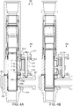
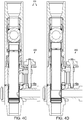
- the ball 111 may be operable between an open position ( Figures 2A , 4A , 4B , 4E, and 4F ) and a closed position ( Figures 4C, 4D , and 5A ) by the bore valve actuator.
- the ball 111 may have a bore formed therethrough corresponding to the housing bore and aligned therewith in the open position.
- a wall of the ball 111 may close an upper portion of the housing bore in the closed position and the ball 111 may engage the seat seal 112s in response to pressure exerted against the ball by fluid injection into the side port 101.
- the port valve 120 may include a closure member, such as a sleeve 121, and a seal mandrel 122.
- the seal mandrel 122 may be made from an erosion resistant material, such as tool steel, ceramic, or cermet.
- the seal mandrel 122 may be disposed within the housing 105 and connected thereto, such as by one or more (two shown) fasteners 123.
- the seal mandrel 122 may have a port formed through a wall thereof corresponding to and aligned with the side port 101.
- Lower seals 124b may be disposed between the housing 105 and the seal mandrel 122 and between the seal mandrel and the sleeve 121 to isolate the interfaces thereof.
- the port valve 120 may have a maximum allowable flow rate greater than, equal to, or slightly less than a flow rate of the drilling fluid 60d in drilling mode.
- the sleeve 121 may be disposed within the housing 105 and longitudinally moveable relative thereto between an open position ( Figure 4D ) and a closed position ( Figures 2A-2C , 4A , and 4F ) by the clamp 200.
- the side port 101 may be in fluid communication with a lower portion of the housing bore.
- the sleeve 121 may isolate the side port 101 from the housing bore by engagement with the lower seals 124b of the seal sleeve 122.
- the sleeve may include an upper portion 121u, a lower portion 121b, and a lug 121c disposed between the upper and lower portions.
- a window 102 may be formed through a wall of the lower housing section 105b and may extend a length corresponding to a stroke of the port valve 120.
- the window 102 may be aligned with the side port 101.
- the lug 121c may be accessible through the window 102.
- a recess 104 may be formed in an outer surface of the lower housing section 105b adjacent to the side port 101 for receiving a stab connector 209 formed at an end of an inlet 207 of the clamp 200.
- Mid seals 124m may be disposed between the housing 105 and the lower cage section 113b and between the lower cage section and the sleeve 121 to isolate the interfaces thereof.
- the bore valve actuator may be mechanical and include a cam 115, a linkage, such as one or more (two shown) pins 116 and slots 121s, and a toggle, such as a split ring 117.
- An upper annulus may be formed between the cage 113 and the upper housing section 105u and a lower annulus may be formed between the valve sleeve 121 and the lower housing section 105b.
- the cam 115 may be disposed in the upper annulus and may be longitudinally movable relative to the housing 105.
- the cam 115 may interact with the ball 111, such as by having one or more (two shown) followers 115f, each formed in an inner surface of a body 115b thereof and extending into a respective cam profile (not shown) formed in an outer surface of the ball 111 or vice versa.
- each follower 115f may be a separate member fastened to the cam body 115b. The ball-cam interaction may rotate the ball 111 between the open and closed positions in response to longitudinal movement of the cam 115 relative to the ball.
- the cam 115 may also interact with the valve sleeve 121 via the linkage.
- the pins 116 may each be fastened to the cam body 115b and each extend into the respective slot 121s formed through a wall of the sleeve upper portion 121u or vice versa.
- the split ring 117 may be fastened to the sleeve 121 by being received in a groove formed in an inner surface of the sleeve upper portion 121u at a lower portion of the slots 121s.
- the lower cage section 113b may have an opening 113o formed therethrough for accommodating the cam-sleeve interaction.
- the linkage may longitudinally connect the cam 115 and the sleeve 121 after allowing a predetermined amount of longitudinal movement therebetween.
- a stroke of the cam 115 may be less than a stroke of the sleeve 121, such that when coupled with the lag created by the linkage, the bore valve 110 and the port valve 120 may never both be fully closed simultaneously ( Figures 4B and 4E ).
- Upper seals 124u may be disposed between the housing 105 and the cam 115 and between the upper cage section 113u and the cam to isolate the interfaces thereof.
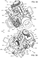
- FIGS 3A-3D illustrate the clamp 200.
- the clamp 200 may include a body 201, a band 202, a latch 205 operable to fasten the band to the body, an inlet 207, one or more actuators, such as port valve actuator 210 and a band actuator 220, and a hub 239.
- the clamp 200 may be movable between an open position (not shown) for receiving the flow sub 100 and a closed position for surrounding an outer surface of the lower housing segment 105b.
- the body 201 may have a lower base portion 201b and an upper stem portion 201s.
- the body 201 may have a coupling, such as a hinge portion, formed at an end of the base portion 201b, and the band 202 may have a mating coupling, such as a hinge portion, formed at a first end thereof.
- the hinge portions may be connected by a fastener, such as a pin 204, thereby pivotally connecting the band 202 and the body 201.
- the band 202 may have a lap formed at a second end thereof for mating with a complementary lap formed at an end of the latch 205. Engagement of the laps may form a lap joint to circumferentially connect the band 202 and the latch 205.
- the body 201 may have a port 201p formed through the base portion 201b for receiving the inlet 207.
- the inlet 207 may be connected to the body 201, such as by a threaded connection.
- a mud saver valve (MSV) 238 may be connected to the inlet 207, such as by a threaded connection.
- An adapter 231 may be connected to the MSV 238 such as by a threaded connection.
- the adapter 231 may have a coupling, such as flange, for receiving a flexible conduit, such as bypass hose 31h.
- the inlet 207 may further have one or more seals 208a,b and a stab connector 209 formed at an end thereof engaging a seal face of the flow sub 100 adjacent to the side port 101.
- the port valve actuator 210 may include the stem portion 201s, a bracket 212, a yoke 213, a hydraulic motor 215, and a gear train 216, 217.
- the body 201 may have a window formed through the stem portion 201s and guide profiles, such as tracks 211, formed in an inner surface of the stem portion adjacent to the window.
- the yoke 213 may extend through the window and have a nut portion 213n, slider portion 213s, and tongue portion 213t. The slider portion 213s may be engaged with the tracks 211, thereby allowing longitudinal movement of the yoke 213 relative to the body 201.
- the yoke 213 may have an engagement profile, such as a lip 213p, formed at an end of the tongue portion 213t for engaging a groove formed in an outer surface of the lug 121c, thereby longitudinally connecting the yoke with the flow sub sleeve 121.
- the hydraulic motor 215 may have a stator connected to the bracket 212, such as by one or more (four shown) fasteners 214, and a rotor connected to a drive gear 216 of the gear train 216, 217.
- the motor 215 may be bidirectional.
- the drive gear 216 may be connected to a yoke gear 217 by meshing of teeth thereof.
- the yoke gear 217 may be connected to a lead screw 218, such as by interference fit or key/keyway.
- the nut portion 213n may be engaged with the lead screw 218 such that the yoke 213 may be being raised and lowered by respective rotation of the lead screw.
- the bracket 212 may be connected to the body 201, such as by one or more (three shown) fasteners 240.
- the lead screw 218 may be supported by the bracket 212 for rotation relative thereto by one or more bearings 219 ( Figure 4A ).
- the motor 215 may be operable to raise and lower the yoke 213 relative to the body 201, thereby also operating the flow sub sleeve 121 when the clamp 200 is engaged with the flow sub 100 ( Figures 4A-4F ).
- the motor 215 may be electric or pneumatic.
- the band actuator 220 may be operable to tightly engage the clamp 200 with the lower housing section 105b after the latch 105 has been fastened.
- the band actuator 220 may include a bracket 222, a hydraulic motor 225, a bearing 229, and a tensioner 224a,b, 226.
- the tensioner 224a,b, 226 may include a tensioner bolt 224a, a stopper 224b, and a tubular tensioner nut 226.
- the motor 225 may have a stator connected to the bearing 229, such as by one or more fasteners (not shown) and a rotor connected to a tensioner bolt 224a.
- the motor 225 may be bidirectional.
- the tensioner bolt 224a may be supported from the body 201 for rotation relative thereto by the bearing 229.
- the bracket 222 may be connected to the body 201, such as by one or more (five shown) fasteners 241.
- the bearing 229 may be connected to the bracket 222, such as by a fastener 242.
- the latch 205 may include an opening formed therethrough for receiving the tensioner nut 226 and a cavity formed therein for facilitating assembly of the tensioner 224a,b, 226.
- the tensioner nut 226 may be connected to a bar 227, such as by fastener 244b and a pin (slightly visible in Figure 3B ).
- the bar 227 may have a slot formed therethrough to accommodate operation of the tensioner 224a,b, 226.
- the bar 227 may also be connected to the bracket, such as by fastener 244a.
- the tensioner nut 226 may rotate relative to the opening and may have a threaded bore for receiving the tensioner bolt 224a.
- Rotation of the tensioner nut 226 may prevent binding of the tensioner bolt 224a and may allow replacement due to wear.
- a stopper 224b may be connected to the bolt 224a with a threaded connection.
- the body 201 may be aligned with the flow sub 100, the band 202 wrapped around the flow sub 100 and the latch 205 engaged with the band 202.
- the motor 225 may then be operated, thereby tightening the clamp 200 around the lower housing section 105b.
- the motor 225 may be electric or pneumatic.
- the clamp 200 may further include one or more handles 230a-d.
- a first handle 230a may be connected to the band 202, such as by a fastener.
- Second 230b and third 230c handles may be connected to the latch 205, such as by respective fasteners.
- a fourth handle 230d may be connected to the bracket 222, such as by a fastener.
- a hub 239 may be connected to the bracket 212, such as by one or more (two shown) fasteners 243.
- the hub 239 may include one or more (four shown) hydraulic connectors 245 for receiving respective hydraulic lines 31c from the hydraulic manifold 39.
- the hub 239 may also include internal hydraulic conduits (not shown), such as tubing, connecting the connectors 245 to respective inlets and outlets of the hydraulic motors 215, 225.
- Each hydraulic motor 215, 225 may further include a motor lock operable between a locked position and an unlocked position.
- Each motor lock may include a clutch torsionally connecting the respective rotor and the stator in the locked position and disengaging the respective rotor from the respective stator in the unlocked position.
- Each clutch may be biased toward the locked position and further include an actuator, such as a piston, operable to move the clutch to the unlocked position in response to hydraulic fluid being supplied to the respective motor.
- each lock may have an additional hydraulic port for supplying the actuator.
- the band 202 and latch 205 may be replaced by automated (i.e., hydraulic) jaws.
- the clamp 200 may be deployed using a beam assembly.
- the beam assembly may include a one or more fasteners, such as bolts, a beam, such as an I-beam, a fastener, such as a plate, and a counterweight.
- the counterweight may be clamped to a first end of the beam using the plate and the bolts.
- a hole may be formed in the second end of the beam for connecting a cable (not shown) which may include a hook for engaging the hoist ring.
- One or more holes (not shown) may be formed through a top of the beam at the center for connecting a sling which may be supported from the derrick 3 by a cable.
- the clamp 200 may be suspended from the derrick 3 and swung into place adjacent the flow sub 100 when needed for adding stands 10s to the drill string 10 and swung into a storage position during drilling.
- the clamp 200 may be deployed using a telescopic arm.
- the telescopic arm may include a piston and cylinder assembly (PCA) and a mounting assembly.
- the PCA may include a two stage hydraulic PCA mounted internally of the arm which may include an outer barrel, an intermediate barrel and an inner barrel.
- the inner barrel may be slidably mounted in the intermediate barrel which is, may be in turn, slidably mounted in the outer barrel.
- the mounting assembly may include a bearer which may be secured to a beam by two bolt and plate assemblies.
- the bearer may include two ears which accommodate trunnions which may project from either side of a carriage.
- the clamp 200 may be moved toward and away from the flow sub 100 by extending and retracting the hydraulic piston and cylinder.
- Figures 4A-4F illustrate operation of the flow sub 100 and the clamp 200.
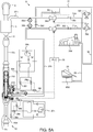
- Figure 5A illustrates the drilling system 1 in a bypass mode.
- Figures 5B and 5C illustrate operation of the drilling system.
- the MSV 238 may be manually operated.
- a position sensor 250 may be operably coupled to the MSV 238 for determining a position (open or closed) of the MSV.
- the position sensor 250 may be in data communication with the PLC 75.
- the MSV 238 may be automated.
- the fluid handling system 1h may further include a second HPU 30h and a second manifold 39. Although two HPUs 30h and two manifolds 39 are shown for operation of the clamp 200, the clamp 200 may be operated with only one HPU and one manifold as shown in Figure 1A .
- Each HPU 30h may include a pump, an accumulator, a check valve, a reservoir having hydraulic fluid, and internal hydraulic conduits connecting the pump, reservoir, accumulator, and check valve.
- Each HPU 30h may further include a pressurized port in fluid communication with the respective accumulator and a drain port in fluid communication with the reservoir.
- Each hydraulic manifold 39 may include one or more automated shutoff valves 39a-d, 39eh in communication with the PLC 75.
- Each manifold 39 may have a pressurized inlet in connected to a first respective pair of the shutoff valves and a drain inlet in fluid communication with a second respective pair of shutoff valves. Each manifold 39 may also have first and second outlets, each outlet connected to a shutoff valve of each pair.
- a first portion of the hydraulic lines 31c may connect respective inlets of the manifolds to respective inlets of the HPUs.
- a second portion of the hydraulic lines 31c may connect respective outlets of the manifolds to respective hydraulic connectors 245 of the clamp hub 239.
- each manifold 39 may include one or more directional control valves, each directional control valve consolidating two or more of the shutoff valves 39a-h.
- drilling may be stopped by stopping advancement and rotation 16 of the top drive 5 and removing weight from the drill bit 15.
- a spider (not shown) may then be operated to engage the drill string 10, thereby longitudinally supporting the drill string 10 from the rig floor 4.
- the clamp 200 may then be transported to the flow sub 100 and closed around the flow sub lower housing section 105b.
- the PLC 75 may then operate the band actuator 220 by opening manifold valves 39a,d, thereby supplying hydraulic fluid to the band motor 225. Operation of the band motor 225 may rotate the tensioner bolt 224a, thereby tightening the clamp 200 into engagement with the flow sub lower housing 105b.
- the PLC 75 may then lock the band motor 225.
- the MSV 238 may be manually opened and then the rig crew may evacuate the rig floor 4.
- the PLC 75 may then test engagement of the seals 208a,b by closing the bypass drain valve 38d and by opening the bypass valve 38b to pressurize the clamp inlet 207 and then closing the bypass valve. If the clamp seals 208a,b are not securely engaged with the lower housing section 105b, drilling fluid 60d will leak past the clamp seals.
- the PLC 75 may verify sealing integrity by monitoring the bypass pressure sensor 35b.
- the PLC may then reopen the bypass valve 38b to equalize pressure on the valve sleeve 121.
- the PLC 75 may then operate the port valve actuator 210 by opening manifold valves 39f,h, thereby supplying hydraulic fluid to the port motor 215. Operation of the port motor 215 may rotate the lead screw 218, thereby raising the yoke 213.
- the sleeve 121 when moved upwardly by the yoke 213, the sleeve 121 may move longitudinally relative to the cam 115 until the split ring 117 engages the pins 116, thereby longitudinally connecting the sleeve and the cam.
- upward movement of the sleeve 121 and the cam 115 may continue, thereby closing the bore valve 110. Due to the lag, discussed above, drilling fluid 60d may momentarily flow into the drill string 10 through both the side port 101 and the bore valve 110. The upward movement may continue until a top of the cam 115 engages the upper housing shoulder 103u.
- the split ring 117 may then be pushed radially inward by further engagement with the pins 116, thereby freeing the cam 115 from the sleeve 121. Upward movement of the sleeve 121 (without the cam 115) may continue until an upper shoulder of the yoke 213 engages an upper shoulder of the stem portion 201s at which point the side port 101 is fully open.
- the PLC 75 may lock the port motor 215 and relieve pressure from the top drive 5 by closing the supply valve 38a and opening the supply drain valve 38c.
- the PLC 75 may then test integrity of the closed bore valve 110 by closing the supply drain valve 38d. If the bore valve 110 has not closed, drilling fluid 60d will leak past the bore valve.
- the PLC 75 may verify closing of the bore valve 110 by monitoring the supply pressure sensor 35d.
- the top drive 5 may then be operated to disconnect from the flow sub 100 and to hoist a stand 10s from pipe rack 17.
- Each stand 10s may include the flow sub 100 and one or more joints of drill pipe 10p.
- the flow sub 100 may be assembled to form an upper end of the respective stand 10s.
- the top drive 5 may continue to be operated to connect to the flow sub 100 of the retrieved stand 10s.
- the top drive 5 may then be operated to connect a lower end of the stand 10s to the flow sub 100 of the drill string 10.
- Drilling fluid 60d may continue to be injected into the side port 101 (via the open supply valve 38b and MSV 238) during adding of the stand 10s by the top drive 5 at a flow rate corresponding to the flow rate in drilling mode.
- the PLC 75 may also utilize the bypass flow meter 34b for performing the mass balance to monitor for a kick or lost circulation during adding of the stand 10s.
- the PLC 75 may pressurize the added stand 10s by closing the supply drain valve 38c and opening the supply valve 38a. Once the stand 10s has been pressurized, the PLC 75 may then unlock the port motor 215. The PLC 75 may then reverse operate the port valve actuator 210 by opening manifold valves 39e,g, thereby reversing supply of the hydraulic fluid to the port motor 215. Operation of the port motor 215 may counter-rotate the lead screw 218, thereby lowering the yoke 213.
- the sleeve 121 when moved downwardly by the yoke 213, the sleeve 121 may move longitudinally relative to the cam 115 until the split ring 117 engages the pins 116, thereby longitudinally connecting the sleeve and the cam. Downward movement of the sleeve 121 and the cam 115 may continue, thereby opening the bore valve 110. Due to the lag, discussed above, drilling fluid 60d may momentarily flow into the drill string 10 through both the side port 101 and the bore valve 110. The downward movement may continue until a bottom of the cam 115 engages a shoulder of the lower cage section 113b.
- the split ring 117 may then be pushed radially inward by further engagement with the pins 116, thereby freeing the cam 115 from the sleeve 121. Downward movement of the sleeve 121 (without the cam 115) may continue until a lower shoulder of the yoke 213 engages a lower shoulder of the stem portion 201s at which point the side port 101 is fully closed.
- the PLC 75 may then relieve pressure from the clamp inlet 207 by closing the bypass valve 38b and opening the bypass drain valve 38d.
- the PLC 75 may then confirm closure of the port sleeve 121 by closing the bypass drain valve 38d and monitoring the bypass pressure sensor 35b. Once closure of the port sleeve 121 has been confirmed, the PLC 75 may open the bypass drain valve 38d.
- the rig crew may then return to the rig floor 4 and close the MSV 238.
- the PLC 75 may then unlock the band motor 225.
- the PLC 75 may then reverse operate the band actuator 220 by opening manifold valves 39b,c, thereby reversing supply of hydraulic fluid to the band motor 225.
- Operation of the band motor 225 may counter-rotate the tensioner bolt 224a, thereby loosening the clamp 200 from engagement with the flow sub lower housing 105b.
- the clamp 200 may then be opened and transported away from the flow sub 100.
- the spider may then be operated to release the drill string 10.
- the top drive 5 may be operated to rotate 16 the drill string 10.
- Weight may be added to the drill bit 15, thereby advancing the drill string 10 into the wellbore 90 and resuming drilling of the wellbore. The process may be repeated until the wellbore 90 has been drilled to total depth or to a depth for setting another string of casing.
- a similar process may be employed if/when the drill string 10 needs to be tripped, such as for replacement of the drill bit 15 and/or to complete the wellbore 90.
- the drill string may be raised (while circulating drilling fluid via the top drive 5) until one of the flow subs 100 is at the rig floor 4.
- the spider may be set (if rotating 16 while tripping, rotation may be halted before setting the spider).
- the clamp 200 may be installed and tested.
- the drilling fluid flow may be switched to the clamp 200 and the bore valve 110 tested.
- the top drive 5 may then be operated to disconnect the stand 10s extending above the rig floor 4 and to hoist the stand to the pipe rack 17.
- the top drive 5 may then be connected to the flow sub 100 at the rig floor 4.
- the top drive 5 may then be pressurized and the drilling fluid flow switched to the top drive.
- the clamp 200 may be bled, the port valve tested, and the clamp removed. Tripping of the drill string from the wellbore may then continue until the drill bit 15 reaches the LMRP. At that point, the BOPs may be closed and circulation may be maintained using the booster 27 and choke 28 lines.
- the method may be utilized for running casing or liner to reinforce and/or drill the wellbore 90, or for assembling work strings to place downhole components in the wellbore.
- the pins 116 may be radially movable relative to the cam 115 between an extended position and a retracted position and be biased toward the retracted position by biasing members, such as springs.
- a recess formed in an inner surface of the upper housing section may allow the pins 116 to retract.
- the pins 116 may still engage the slots 121s in the retracted position but may be clear of the split ring 117.
- the cam 115 and sleeve 121 may be longitudinally connected during the upper stroke by the pins engaging a bottom of the respective slots. Once the cam 115 moves upward, the upper housing inner surface may force the pins 116 to extend.
- the extended pins 116 may then catch the split ring 117 on the downward stroke until the pins are aligned with the housing recess.
- the split ring 117 may be movable between an extended position and a retracted position by engagement with an inclined surface formed in an inner surface of the lower cage section 113b.
- the port valve actuator 210 may include a piston and cylinder assembly (PCA) instead of the hydraulic motor 215 and the band actuator 220 may include a PCA and a first hinge segment instead of the hydraulic motor 225, tensioner 224a,b, 232, and latch 205.
- the modified clamp may include a second band pivotally connected to the band 202 at a first end thereof and having a second hinge segment complementing the first hinge segment formed at a second end thereof.
- a cylinder of the port PCA may be connected to the clamp body 201, such as by fastening.
- a piston of the port PCA may be connected to the yoke 213, such as by fastening.
- the port PCA may be operable to raise and lower the yoke 213 relative to the body 201 when the modified clamp is engaged with a modified flow sub ( Figures 8A-9B of the '322 provisional).
- a longitudinal centerline of the port PCA may be offset from a longitudinal centerline of the stem portion 201s and the flow sub window 102 may be correspondingly offset from the flow sub port 101.
- a cylinder of the band PCA may be connected to the clamp body 201, such as by fastening.
- a piston of the band PCA may be connected to the first hinge segment, such as by a threaded connection.
- the band PCA may be connected to the second band by insertion of a fastener, such as hinge pin, through the first and second hinge segments.
- the clamp body 201 may be aligned with the modified flow sub, the bands wrapped around the flow sub and the hinge pin inserted through the hinge segments.
- the band PCA may then be retracted, thereby tightening the modified clamp around the lower housing section of the modified flow sub.
- the flow sub PCA of the modified clamp may be connected to the stem portion 201s such that the longitudinal centerline of the flow sub PCA is aligned with the longitudinal centerline of the stem portion 201s and the further modified clamp may be used with the flow sub 100 (without modification).
- FIG. 6 illustrate a flow sub 300 and clamp 350, according to another embodiment of the present disclosure.
- the flow sub 300 may include a tubular housing, a bore valve (not shown, see Figures 2A-2C of the '322 provisional application), a bore valve actuator (not shown, see Figures 2A-2C of the '322 provisional application), a side port valve (not shown, see Figures 2A-2C of the '322 provisional application), and a side port valve actuator.
- the bore valve and bore valve actuator may be similar to those of the flow sub 100.
- the port valve may be actuated by hydraulic interaction with the clamp 350.
- the port valve actuator may be hydraulic and include a piston (not shown, see Figures 2A-2C of the '322 provisional application), one or more hydraulic ports, such as opener inlet 324i and outlet 324o ports and closer inlet 323i and outlet 323o ports, one or more seals, one or more hydraulic chambers (not shown, see Figures 2A-2C of the '322 provisional application), such as an opener and a closer, one or more hydraulic valves 326i,o, 327i,o.
- the piston may be integral with the sleeve (not shown, see Figures 2A-2C of the '322 provisional application) or be a separate member connected thereto, such as by fastening.
- the piston may be disposed in a lower annulus of the flow sub housing and may divide the lower annulus into the two hydraulic chambers. Seals (not shown) may be disposed as needed to isolate the hydraulic chambers.
- the port valve actuator may include a biasing member, such as a spring, for closing instead of the closer chamber, ports, and valves.
- the hydraulic ports 323i,o, 324i,o may extend radially and circumferentially through a wall of a lower housing section of the flow sub 300 to accommodate placement of the hydraulic valves 326i,o, 327i,o.
- Each hydraulic valve 326i,o, 327i,o may be disposed in a respective hydraulic port 323i,o, 324i,o.
- the hydraulic valves 326i,o, 327i,o are shown externally of the ports for the sake of clarity only.
- the inlet hydraulic valves 326i, 327i may each be a check valve operable to allow hydraulic fluid flow from the HPU 30h to the hydraulic chambers and prevent reverse flow from the chambers to the HPU.
- Each check valve may include a spring having substantial stiffness so as to prevent return fluid from entering the respective chamber should an annulus pressure spike occur while the flow sub 300 is in the wellbore 90.
- the outlet hydraulic valves 326o, 327o may each be a pressure relief valve operable to allow hydraulic fluid flow from the respective hydraulic chamber to the HPU 30h when pressure in the chamber exceeds pressure in the HPU by a predetermined differential pressure.
- the differential pressure may be set to be equal to or substantially equal to the drilling fluid pressure so that the pressure in the hydraulic chambers remains equal to or slightly greater than the drilling fluid pressure, thereby ensuring that drilling fluid 60d does not leak into the hydraulic chambers.
- the clamp 350 may include a body, one or more bands pivoted to the body, such as by a hinge (not shown), and a latch (not shown) operable to fasten the bands to the body.
- the clamp 350 may be movable between an open position for receiving the flow sub 300 and a closed position for surrounding an outer surface of the flow sub lower housing segment.
- the clamp 350 may further include a tensionser (not shown) operable to tightly engage the clamp with the flow sub lower housing section after the latch has been fastened.
- the clamp body may have a circulation port (not shown) formed therethrough and hydraulic ports (not shown) formed therethrough corresponding to the respective hydraulic ports 323i,o, 324i,o.
- the clamp body may further have an inlet for connection to the MSV 238.
- the clamp body may further have a gasket disposed in an inner surface thereof and having openings corresponding to the body ports. When engaged with the flow sub lower housing section, the gasket may provide sealed fluid communication between the clamp body ports and respective lower housing ports 301, 323i,o, 324i,o.
- Each of the clamp body and the flow sub lower housing section may further include mating locator profiles, such as a dowels (not shown) and mating recesses 302 formed in an outer surface of the lower housing section (or vice versa) for alignment of the clamp body with the lower housing section.
- the HPU 30h may be connected to the flow sub 300 via the clamp 350.
- the manifold may include an opener control valve 339o and a closer control valve 339c.
- the control valves 339o,c may each be directional valves having an electric, hydraulic, or pneumatic actuator in communication with the PLC 75.
- Each control valve 310o,c may be operable between two or more positions P1-P4 and may fail to the closed position P1. In the open positions P2-P4, each control valve 310o,c may selectively provide fluid communication between one or more of the flow sub hydraulic valves 326i,o, 327i,o and one or more of the HPU accumulator and HPU reservoir.
- drilling may be stopped by stopping advancement and rotation of the top drive 5 and removing weight from the drill bit 15.
- the spider may then be operated to engage the drill string, thereby longitudinally supporting the drill string 310 from the rig floor 4.
- the clamp 350 may be transported to the flow sub 300, closed, and tightened to engage the flow sub lower housing section.
- the PLC 75 may then test engagement of the clamp 350 by closing the bypass drain valve 38d and by opening the bypass valve 38b and MSV 238 to pressurize the clamp inlet and then closing the bypass valve. If the gasket is not securely engaged with the flow sub lower housing section, drilling fluid 60d will leak past the gasket.
- the PLC 75 may verify sealing integrity by monitoring the bypass pressure sensor 35b. The PLC may then reopen the bypass valve 38b to equalize pressure on the flow sub valve sleeve.
- the PLC 75 may then operate the port valve actuator by opening the opener control valve 310o to the second position P2, thereby providing fluid communication between the HPU accumulator and the opener inlet valve 327i and between the HPU reservoir and the opener outlet valve 327o.
- the HPU accumulator may then inject hydraulic fluid into the flow sub opener chamber. Once pressure in the opener chamber exceeds the differential pressure, hydraulic fluid may exit the opener chamber through the opener outlet valve 327o to the HPU reservoir, thereby displacing any air from the opener chamber.
- the PLC 75 may shift the opener control valve 310o to the third position P3 and open the closer control valve 310c to the second position P2, thereby providing fluid communication between the HPU accumulator and the opener inlet valve 327i, preventing fluid communication between the HPU reservoir and the opener outlet valve 327o, and providing fluid communication between both closer valves 326i,o and the HPU reservoir.
- the HPU accumulator may then inject hydraulic fluid into the flow sub opener chamber.
- the PLC 75 may verify opening of the port sleeve by monitoring the supply 34b and/or bypass 34b flow meters. The PLC 75 may then test integrity of the closed bore valve by closing the supply valve 38a and by opening the supply drain valve 38c to relieve pressure from the top drive 5 and then closing the supply drain valve. The PLC 75 may verify closing of the bore valve by monitoring the supply pressure sensor 35d.
- the top drive 5 may then be operated to disconnect from the flow sub 300 and to hoist a stand 310s from pipe rack 17.
- the top drive 5 may continue to be operated to connect to the flow sub (not shown, see flow sub 300) of the retrieved stand 310s.
- the top drive 5 may then be operated to connect a lower end of the stand 310s to the flow sub 300 of the drill string 310.
- Drilling fluid 60d may continue to be injected into the side port (via the open supply valve 38b and MSV 238) during adding of the stand 310s by the top drive 5 at a flow rate corresponding to the flow rate in drilling mode.
- the PLC 75 may also utilize the bypass flow meter 34b for performing the mass balance to monitor for a kick or lost circulation during adding of the stand 310s.
- the PLC 75 may pressurize the added stand 310s by closing the supply drain valve 38c and opening the supply valve 38a. The PLC 75 may then shift the opener control valve 310o to the fourth position P4 and shift the closer control valve 310c to the third position P3, thereby providing fluid communication between the HPU accumulator and the closer inlet valve 326i, providing fluid communication between the HPU reservoir and the closer outlet valve 326o, and providing fluid communication between both opener valves 327i,o and the HPU reservoir.
- the PLC 75 may shift the closer control valve 310c to the fourth position P4, thereby providing fluid communication between the HPU accumulator and the closer inlet valve 326i and preventing fluid communication between the HPU reservoir and the closer outlet valve 326o.
- the HPU accumulator may then inject hydraulic fluid into the flow sub closer chamber.
- the flow sub port sleeve may move downward to the closed position, thereby also opening the flow sub bore valve. Due to the lag, discussed above, drilling fluid 60d may momentarily flow into the drill string 310 through both the side port 302 and the flow sub bore valve.
- the PLC 75 may verify closing of the flow sub port sleeve by monitoring the supply 34b and/or bypass 34b flow meters.
- the PLC 75 may then relieve pressure from the clamp inlet 207 by closing the bypass valve 38b and opening the bypass drain valve 38d.
- the PLC 75 may then confirm closure of the flow sub port sleeve by closing the bypass drain valve 38d and monitoring the bypass pressure sensor 5b.
- the PLC 75 may close P1 both control valves 310o,c and open the bypass drain valve 38d.
- the clamp 350 may then be loosened from engagement with the flow sub lower housing.
- the clamp 350 may then be opened and transported away from the flow sub 300.
- the spider may then be operated to release the drill string 310. Once released, the top drive 5 may be operated to rotate 16 the drill string 310.
- Weight may be added to the drill bit 15, thereby advancing the drill string 310 into the wellbore 90 and resuming drilling of the wellbore. The process may be repeated until the wellbore 90 has been drilled to total depth or to a depth for setting another string of casing.
- FIG. 7A illustrates a flow sub 400, according to another embodiment of the present disclosure.
- Figure 7B illustrates operation of the flow sub 400 with a UMRP 450.
- the flow sub 400 may include a tubular housing 405, the bore valve 110, the bore valve actuator, a side port valve 420, and a side port valve actuator.
- the housing 405 may include one or more sections 405a,b each section connected together, such as by fastening with a threaded connection.
- the housing 405 may have a central longitudinal bore therethrough and a radial flow port 401 formed through a wall thereof in fluid communication with the bore and located at a side of one of the housing sections 405b.
- the housing 405 may also have a threaded coupling formed at each longitudinal end, such as a box formed in an upper longitudinal end and a pin formed on a lower longitudinal end, so that the housing may be assembled as part of the drill string 410.
- the port valve 420 may include a closure member, such as a sleeve 421, and a seal mandrel 422.
- the seal mandrel 422 may be made from an erosion resistant material, such as tool steel, ceramic, or cermet.
- the seal mandrel 422 may be disposed within the housing 405 and connected thereto, such as by one or more (two shown) fasteners 423.
- the seal mandrel 422 may have a port formed through a wall thereof corresponding to and aligned with the housing port 401. Seals 424 may be disposed between the housing 405 and the seal mandrel 422 and between the seal mandrel and the sleeve 421 to isolate the interfaces thereof.
- the port valve 420 may have a maximum allowable flow rate greater than, equal to, or slightly less than a flow rate of the drilling fluid 60d in drilling mode.
- the sleeve 421 may be disposed within the housing 405 and longitudinally movable relative thereto between an open position ( Figure 7B ) and a closed position ( Figure 7A ) by the port valve actuator.
- the port valve actuator may be hydraulic and include a piston 431, a hydraulic port 433, a hydraulic passage 434, a piston seal 432, one or more hydraulic chambers, such as an opener 435o and a closer 435c, and a biasing member, such as a spring 436.
- the piston 431 may be integral with the sleeve 421 or be a separate member connected thereto, such as by fastening.
- the piston 431 may be disposed in a lower annulus of the housing and may divide the lower annulus into the two hydraulic chambers 435o,c.
- the piston seal 432 may be carried by the piston 431 and may isolate the chambers 435o,c.
- the spring 436 may be disposed in the closer chamber 435c and against the piston 431, thereby biasing the sleeve 421 toward the closed position.
- the hydraulic passage 434 may be formed between the sleeve 421 and the seal mandrel 422 and may provide fluid communication between the side port 401 and the opener chamber 435o.
- the side port 401 may be in fluid communication with a lower portion of the housing bore.
- the sleeve 421 may isolate the side port 401 from the housing bore by engagement with the seals 424 of the seal sleeve 422.
- the chambers 435o,c may be balanced due to the closer chamber 435c being in fluid communication with the returns 60r via the hydraulic port 433 and the opener chamber 435o also being in fluid communication with the returns via the passage 434 and the side port 401.
- the spring 436 may therefore be unopposed in keeping the side port valve 420 in the closed position.
- the port valve actuator may be operated by drilling fluid 60d selectively injected and relieved from the chambers 435o,c.
- the UMRP 450 may include the diverter (not shown, see diverter 21), the flex joint (not shown, see flex joint 22), the slip joint (not shown, see slip joint 23), the tensioner (not shown, see tensioner 24), the RCD 26, one or more BOPs 455a,b, and one or more flow crosses 460a,b.
- the BOPs 455a,b may be operated between an engaged position ( Figure 7B ) and a disengaged position (not shown).
- the BOPs 455a,b may be ram type (shown) or annular type (not shown).
- the BOPs 455a,b may be operable to extend into engagement with and seal against an outer surface of the flow sub housing 405, thereby dividing an annulus formed between the flow sub 400 and the UMRP 450 into a vent chamber 465v, a an injection chamber 465i, and a returns chamber 465r.
- the BOPs and shutoff valve 488 may be operated by the PLC 75 via the auxiliary umbilical 71 and the auxiliary HPU.
- the shutoff valve 488 may be connected to a branch of the upper flow cross 460u.
- a lower end of a bypass hose 481 may be connected to the shutoff valve 488 and an upper end of the bypass hose 481 may be connected to a piped portion 31p of the bypass line 31p,h instead of the bypass hose 31h.
- a lower end of an auxiliary returns line 479 may be connected to a branch of the lower flow cross 460b and an upper end of the auxiliary returns line may be connected to a lower end of the returns line 29.
- each flow sub 400 may be located along the drill string 410/stand (not shown) such that when the spider is engaged with the drill string, one of the flow subs 400 may be aligned with the UMRP 450.
- the alignment may ensure that when the BOPs 455a,b engage (and RCD 26 already engaged) the flow sub 400, the hydraulic port 433 is disposed in the vent chamber 465v and the side port 401 is disposed in the injection chamber 465i.
- Drilling fluid 60d pumped into the injection chamber 465i via the bypass line 31p, 481 may serve the dual purpose of opening the side port valve 420 and flowing through the side port 401 to maintain circulation of drilling fluid in the wellbore 90 while the additional stand to the drill string 410.
- Injection of the drilling fluid 60d may pressurize the opener chamber 435o via the side port 401 and hydraulic passage 434 while the closer chamber 435c is maintained at annulus pressure by fluid communication with the vent chamber 465v via the hydraulic port 433.
- the sleeve 421 may move upward to the open position.
- an RCD may be used instead of each BOP 455a,b, thereby allowing the flow sub 400 to be rotated while adding the stand to the drill string 410.
- the drilling rig 1r may include a rotary table for rotating the drill string 410 as the stand is being added by the top drive 5.
- the PLC 75 may synchronize rotation between the top drive 5 and the rotary table to effect continuous rotation while adding the stand to the drill string 10.
- Equipment suitable for use with such a continuous rotating drilling system is illustrated at Figure 5A of US Pat. Pub. App. No. 2011/01 55379 .
- the flow sub 400 may be modified to include a rotary swivel as also discussed and illustrated in the '379 publication.
Landscapes
- Engineering & Computer Science (AREA)
- Geology (AREA)
- Life Sciences & Earth Sciences (AREA)
- Mining & Mineral Resources (AREA)
- Physics & Mathematics (AREA)
- Environmental & Geological Engineering (AREA)
- Fluid Mechanics (AREA)
- General Life Sciences & Earth Sciences (AREA)
- Geochemistry & Mineralogy (AREA)
- Mechanical Engineering (AREA)
- Earth Drilling (AREA)
- Pipe Accessories (AREA)
- Lift Valve (AREA)
- Geophysics (AREA)
Description
- This application claims the benefit of
U.S. Provisional Patent Application No. 61/537,322, filed on September 21, 2011 U.S. Patent Application Serial No. 13/596,987, Filed on August 28, 2012 - The present invention relates to a three way flow sub for continuous circulation.
- In many drilling operations to recover hydrocarbons, a drill string made by assembling joints of drill pipe with threaded connections and having a drill bit at the bottom is rotated to move the drill bit. Typically drilling fluid, such as oil or water based mud, is circulated to and through the drill bit to lubricate and cool the bit and to facilitate the removal of cuttings from the wellbore that is being formed. The drilling fluid and cuttings returns to the surface via an annulus formed between the drill string and the wellbore. At the surface, the cuttings are removed from the drilling fluid and the drilling fluid is recycled.
WO2009022914 , considered the closest prior art, describes a cylindrical valve section for including in a drill string,GB2378199 EP0606981 ,GB2118998 GB2159194 - As the drill bit penetrates into the earth and the wellbore is lengthened, more joints of drill pipe are added to the drill string. This involves stopping the drilling while the joints are added. The process is reversed when the drill string is removed or tripped, e.g., to replace the drill bit or to perform other wellbore operations. Interruption of drilling may mean that the circulation of the mud stops and has to be re-started when drilling resumes. This can be time consuming, can cause deleterious effects on the walls of the wellbore being drilled, and can lead to formation damage and problems in maintaining an open wellbore. Also, a particular mud weight may be chosen to provide a static head relating to the ambient pressure at the top of a drill string when it is open while joints are being added or removed. The weighting of the mud can be very expensive.
- To convey drilled cuttings away from a drill bit and up and out of a wellbore being drilled, the cuttings are maintained in suspension in the drilling fluid. If the flow of fluid with cuttings suspended in it ceases, the cuttings tend to fall within the fluid. This is inhibited by using relatively viscous drilling fluid; but thicker fluids require more power to pump. Further, restarting fluid circulation following a cessation of circulation may result in the overpressuring of a formation in which the wellbore is being formed.
- The present disclosure relates to a three way flow sub for continuous circulation. In a first aspect, a flow sub for use with a drill string includes a tubular housing having a longitudinal bore formed therethrough and a flow port formed through a wall thereof; a bore valve operable between an open position and a closed position, wherein the bore valve isolates an upper portion of the bore from a lower portion of the bore in the closed position; and a sleeve disposed in the housing and movable between an open position where the flow port is exposed to the bore and a closed position where a wall of the sleeve isolates the flow port and the bore; and a bore valve actuator operably coupling the sleeve and the bore valve such that opening the sleeve closes the bore valve and closing the sleeve opens the bore valve. The bore valve actuator longitudinally connects to the sleeve after allowing the sleeve to have a predetermined amount of longitudinal movement, and the bore valve actuator is operable to close the bore valve after the sleeve is at least partially open and open the bore valve before the sleeve is fully closed
- In another aspect, a method for drilling a wellbore includes: disposing a tubular string in the wellbore, wherein the tubular string includes a drill bit disposed at a bottom and a flow sub disposed on a top thereof; injecting drilling fluid through a bore valve in the flow sub to rotate the drill bit; moving a sleeve in the flow sub longitudinally to at least partially open a flow port formed through a wall of the flow sub; engaging the sleeve and the bore valve after moving the sleeve for a predetermined amount of longitudinal movement; moving the sleeve to further open the flow port, thereby also automatically closing the bore valve which isolates the top of the tubular string from the flow port and injecting the drilling fluid into the flow port while adding a stand to the tubular string. Injection of drilling fluid into the tubular string is continuously maintained between drilling and adding the stand to the tubular string.
- So that the manner in which the above recited features of the present disclosure can be understood in detail, a more particular description of the disclosure, briefly summarized above, may be had by reference to embodiments, some of which are illustrated in the appended drawings. It is to be noted, however, that the appended drawings illustrate only typical embodiments of this disclosure and are therefore not to be considered limiting of its scope, for the disclosure may admit to other equally effective embodiments.
-
Figures 1A-1C illustrate a drilling system in a drilling mode, according to one embodiment of the present disclosure. -
Figures 2A-2C illustrate a flow sub of the drilling system in a top injection mode. -
Figures 3A-3D illustrate a clamp of the drilling system. -
Figures 4A-4F illustrate operation of the flow sub and the clamp. -
Figure 5A illustrates the drilling system in a bypass mode.Figures 5B and5C illustrate operation of the drilling system. -
Figure 6 illustrate a flow sub and clamp, according to another embodiment of the present disclosure. -
Figure 7A illustrates a flow sub, according to another embodiment of the present invention.Figure 7B illustrates operation of the flow sub with an upper marine riser package (UMRP). -
Figures 1A-1C illustrate adrilling system 1 in a drilling mode, according to one embodiment of the present disclosure. Thedrilling system 1 may include a mobile offshore drilling unit (MODU) 1m, such as a semi-submersible, adrilling rig 1r, afluid handling system 1h, afluid transport system 1t, and a pressure control assembly (PCA) 1p. The MODU 1m may carry thedrilling rig 1r and thefluid handling system 1h aboard and may include a moon pool, through which drilling operations are conducted. Thesemi-submersible MODU 1m may include a lower barge hull which floats below a surface (aka waterline) 2s ofsea 2 and is, therefore, less subject to surface wave action. Stability columns (only one shown) may be mounted on the lower barge hull for supporting an upper hull above the waterline. The upper hull may have one or more decks for carrying thedrilling rig 1r andfluid handling system 1h. TheMODU 1m may further have a dynamic positioning system (DPS) (not shown) or be moored for maintaining the moon pool in position over asubsea wellhead 50. - Alternatively, a fixed offshore drilling unit or a non-mobile floating offshore drilling unit may be used instead of the
MODU 1m. Alternatively, the wellbore may be subsea having a wellhead located adjacent to the waterline and the drilling rig may be a located on a platform adjacent the wellhead. Alternatively, the drilling system may be used for drilling a subterranean (aka land based) wellbore and theMODU 1m may be omitted. - The
drilling rig 1r may include aderrick 3 having a rig floor 4 at its lower end having an opening corresponding to the moonpool. Thedrilling rig 1r may further include atop drive 5. Thetop drive 5 may include a motor for rotating 16 adrill string 10. The top drive motor may be electric or hydraulic. A housing of thetop drive 5 may be coupled to a rail (not shown) of thederrick 3 for preventing rotation of the top drive housing during rotation of thedrill string 10 and allowing for vertical movement of the top drive with atraveling block 6. A housing of thetop drive 5 may be suspended from thederrick 3 by thetraveling block 6. Thetraveling block 6 may be supported by wire rope 7 connected at its upper end to acrown block 8. The wire rope 7 may be woven through sheaves of theblocks drawworks 9 for reeling thereof, thereby raising or lowering thetraveling block 6 relative to thederrick 3. A Kellyvalve 11 may be connected to a quill of atop drive 5. A top of thedrill string 10 may be connected to the Kellyvalve 11, such as by a threaded connection or by a gripper (not shown), such as a torque head or spear. Thedrilling rig 1r may further include a drill string compensator (not shown) to account for heave of theMODU 1m. The drill string compensator may be disposed between thetraveling block 6 and the top drive 5 (aka hook mounted) or between thecrown block 8 and the derrick 3 (aka top mounted). - The
fluid transport system 1t may include thedrill string 10, an upper marine riser package (UMRP) 20, amarine riser 25, abooster line 27, and achoke line 28. Thedrill string 10 may include a bottomhole assembly (BHA) 10b, joints ofdrill pipe 10p connected together, such as by threaded couplings (Figure 5A ), and one or more (four shown)flow subs 100. The BHA 10b may be connected to thedrill pipe 10p, such as by a threaded connection, and include adrill bit 15 and one ormore drill collars 12 connected thereto, such as by a threaded connection. Thedrill bit 15 may be rotated 16 by thetop drive 5 via thedrill pipe 10p and/or theBHA 10b may further include a drilling motor (not shown) for rotating the drill bit. TheBHA 10b may further include an instrumentation sub (not shown), such as a measurement while drilling (MWD) and/or a logging while drilling (LWD) sub. - The PCA 1p may be connected to a
wellhead 50 adjacently located to afloor 2f of thesea 2. Aconductor string 51 may be driven into theseafloor 2f. Theconductor string 51 may include a housing and joints of conductor pipe connected together, such as by threaded connections. Once theconductor string 51 has been set, asubsea wellbore 90 may be drilled into theseafloor 2f and afirst casing string 52 may be deployed into the wellbore. Thefirst casing string 52 may include a wellhead housing and joints of casing connected together, such as by threaded connections. The wellhead housing may land in the conductor housing during deployment of thefirst casing string 52. Thefirst casing string 52 may be cemented 91 into thewellbore 90. Thefirst casing string 52 may extend to a depth adjacent a bottom of anupper formation 94u. Theupper formation 94u may be non-productive and alower formation 94b may be a hydrocarbon-bearing reservoir. Alternatively, thelower formation 94b may be environmentally sensitive, such as an aquifer, or unstable. Although shown as vertical, thewellbore 90 may include a vertical portion and a deviated, such as horizontal, portion. - The PCA 1p may include a
wellhead adapter 40b, one ormore flow crosses 41u,m,b, one or more blow out preventers (BOPs) 42a,u,b, a lower marine riser package (LMRP), one ormore accumulators 44, and areceiver 46. The LMRP may include acontrol pod 76, a flex joint 43, and aconnector 40u. Thewellhead adapter 40b, flow crosses 41u,m,b,BOPs 42a,u,b,receiver 46,connector 40u, and flex joint 43, may each include a housing having a longitudinal bore therethrough and may each be connected, such as by flanges, such that a continuous bore is maintained therethrough. The bore may have drift diameter, corresponding to a drift diameter of thewellhead 50. - Each of the
connector 40u andwellhead adapter 40b may include one or more fasteners, such as dogs, for fastening the LMRP to theBOPs 42a,u,b and the PCA 1p to an external profile of the wellhead housing, respectively. Each of theconnector 40u andwellhead adapter 40b may further include a seal sleeve for engaging an internal profile of therespective receiver 46 and wellhead housing. Each of theconnector 40u andwellhead adapter 40b may be in electric or hydraulic communication with thecontrol pod 76 and/or further include an electric or hydraulic actuator and an interface, such as a hot stab, so that a remotely operated subsea vehicle (ROV) (not shown) may operate the actuator for engaging the dogs with the external profile. - The LMRP may receive a lower end of the
riser 25 and connect the riser to the PCA 1p. Thecontrol pod 76 may be in electric, hydraulic, and/or optical communication with a programmable logic controller (PLC) 75 onboard theMODU 1m via an umbilical 70. Thecontrol pod 76 may include one or more control valves (not shown) in communication with theBOPs 42a,u,b for operation thereof. Each control valve may include an electric or hydraulic actuator in communication with the umbilical 70. The umbilical 70 may include one or more hydraulic or electric control conduit/cables for the actuators. Theaccumulators 44 may store pressurized hydraulic fluid for operating theBOPs 42a,u,b. Additionally, theaccumulators 44 may be used for operating one or more of the other components of the PCA 1p. The umbilical 70 may further include hydraulic, electric, and/or optic control conduit/cables for operating various functions of the PCA 1p. ThePLC 75 may operate the PCA 1p via the umbilical 70 and thecontrol pod 76. - A lower end of the
booster line 27 may be connected to a branch of theflow cross 41u by ashutoff valve 45a. A booster manifold may also connect to the booster line lower end and have a prong connected to a respective branch of eachflow cross 41m,b.Shutoff valves 45b,c may be disposed in respective prongs of the booster manifold. Alternatively, a separate kill line (not shown) may be connected to the branches of the flow crosses 41m,b instead of the booster manifold. An upper end of thebooster line 27 may be connected to an outlet of a booster pump (not shown). A lower end of thechoke line 28 may have prongs connected to respective second branches of the flow crosses 41m,b.Shutoff valves 45d,e may be disposed in respective prongs of the choke line lower end. - A
pressure sensor 47a may be connected to a second branch of theupper flow cross 41u.Pressure sensors 47b,c may be connected to the choke line prongs betweenrespective shutoff valves 45d,e and respective flow cross second branches. Eachpressure sensor 47a-c may be in data communication with thecontrol pod 76. Thelines MODU 1m and the PCA 1p by being fastened to brackets disposed along theriser 25. Eachline shutoff valve 45a-e may be automated and have a hydraulic actuator (not shown) operable by thecontrol pod 76 via fluid communication with a respective umbilical conduit or theLMRP accumulators 44. Alternatively, the valve actuators may be electrical or pneumatic. - The
riser 25 may extend from the PCA 1p to theMODU 1m and may connect to the MODU via theUMRP 20. TheUMRP 20 may include adiverter 21, a flex joint 22, a slip (aka telescopic) joint 23, atensioner 24, and a rotating control device (RCD) 26. A lower end of theRCD 26 may be connected to an upper end of theriser 25, such as by a flanged connection. The slip joint 23 may include an outer barrel connected to an upper end of theRCD 26, such as by a flanged connection, and an inner barrel connected to the flex joint 22, such as by a flanged connection. The outer barrel may also be connected to thetensioner 24, such as by a tensioner ring (not shown). - The flex joint 22 may also connect to the
diverter 21, such as by a flanged connection. Thediverter 21 may also be connected to the rig floor 4, such as by a bracket. The slip joint 23 may be operable to extend and retract in response to heave of theMODU 1m relative to theriser 25 while thetensioner 24 may reel wire rope in response to the heave, thereby supporting theriser 25 from theMODU 1m while accommodating the heave. The flex joints 23, 43 may accommodate respective horizontal and/or rotational (aka pitch and roll) movement of theMODU 1m relative to theriser 25 and the riser relative to the PCA 1p. Theriser 25 may have one or more buoyancy modules (not shown) disposed therealong to reduce load on thetensioner 24. - The RCD 26 (see also
Figure 7B ) may include a housing, a piston, a latch, and a rider. The housing may be tubular and have one or more sections connected together, such as by flanged connections. The rider may include a bearing assembly, one or more stripper seals, and a catch, such as a sleeve. The rider may be selectively longitudinally and torsionally connected to the housing by engagement of the latch with the catch sleeve. The housing may have hydraulic ports in fluid communication with the piston and an interface of the RCD. The bearing assembly may be connected to the stripper seals. The bearing assembly may allow the stripper seals to rotate relative to the housing. The bearing assembly may include one or more radial bearings, one or more thrust bearings, and a self contained lubricant system. - Each stripper seal may be directional and oriented to seal against the
drill pipe 10p in response to higher pressure in theriser 25 than the UMRP 20 (components thereof above the RCD). In operation, thedrill pipe 10p may be received through the rider so that the stripper seals may engage the drill pipe in response to sufficient pressure differential. Each stripper seal may also be flexible enough to seal against an outer surface of thedrill pipe 10p having a pipe diameter and an outer surface of threaded couplings of the drill pipe having a larger tool joint diameter. TheRCD 26 may provide a desired barrier in theriser 25 either when the drill pipe is stationary or rotating. Alternatively, an active seal RCD may be used. The RCD housing may be submerged adjacent thewaterline 2s. The RCD interface may be in fluid communication with an auxiliary hydraulic power unit (HPU) (not shown) of thePLC 75 via an auxiliary umbilical 71. - Alternatively, the rider may be non-releasably connected to the housing. Alternatively, the RCD may be located above the waterline and/or along the UMRP at any other location besides a lower end thereof. Alternatively, the RCD may be located at an upper end of the UMRP and the slip joint 23 and bracket connecting the UMRP to the rig may be omitted or the slip joint may be locked instead of being omitted. Alternatively, the RCD may be assembled as part of the riser at any location therealong.
- The
fluid handling system 1h may include areturn line 29,mud pump 30d, one or more hydraulic power units (HPUs) 30h (one shown inFigure 1A and two shown inFigure 5A ), abypass line 31p,h, one or morehydraulic lines 31c, adrain line 32, a solids separator, such as ashale shaker 33, one ormore flow meters 34b,d,r, one ormore pressure sensors 35b,d,r, one or more variable choke valves, such aschokes 36f,p,r, asupply line 37p,h, one ormore shutoff valves 38a-d, ahydraulic manifold 39, and aclamp 200. - A lower end of the
return line 29 may be connected to an outlet of theRCD 26 and an upper end of the return line may be connected to an inlet of themud pump 30d. Thereturns pressure sensor 35r, returns choke 36r, returnsflow meter 34r, andshale shaker 33 may be assembled as part of thereturn line 29. A lower end of thesupply line 37p,h may be connected to an outlet of themud pump 30d and an upper end of the supply line may be connected to an inlet of thetop drive 5. Thesupply pressure sensor 35d,supply flow meter 34d, andsupply shutoff valve 38a may be assembled as part of thesupply line 37p,h. A first end of thebypass line 31p,h may be connected to an outlet of themud pump 30d and a second end of the bypass line may be connected to an inlet 207 (Figure 3A ) of theclamp 200. Thebypass pressure sensor 35b,bypass flow meter 34b, andbypass shutoff valve 38b may be assembled as part of thebypass line 31p,h. - A first end of the
drain line 32 may be connected to thereturn line 29 and a second portion of the drain line may have prongs (four shown). A first drain prong may be connected to thebypass line 31p,h. A second drain prong may be connected to thesupply line 37p,h. Third and fourth drain prongs may be connected to an outlet of themud pump 30d. Thesupply drain valve 38c,bypass drain valve 38d,pressure choke 36p, and flowchoke 36f may be assembled as part of thedrain line 32. A first end of thehydraulic lines 31c may be connected to theHPU 30h and a second end of the hydraulic lines may be connected to theclamp 200. Thehydraulic manifold 39 may be assembled as part of thehydraulic lines 31c. - Each
choke 36f,p,r may include a hydraulic actuator operated by thePLC 75 via the auxiliary HPU (not shown). The returns choke 36r may be operated by the PLC to maintain backpressure in theriser 25. Theflow choke 36f may be operated (Figure 5B ) by thePLC 75 to prevent a flow rate supplied to theflow sub 100 and clamp 200 in bypass mode (Figure 5A ) from exceeding a maximum allowable flow rate of the flow sub and/or clamp. Alternatively, the choke actuators may be electrical or pneumatic. Thepressure choke 36p may be operated by thePLC 75 to protect against overpressure of theclamp 200 by themud pump 30d. Eachshutoff valve 38a-d may be automated and have a hydraulic actuator (not shown) operable by thePLC 75 via the auxiliary HPU. Alternatively, the valve actuators may be electrical or pneumatic. - Each
pressure sensor 35b,d,r may be in data communication with thePLC 75. Thereturns pressure sensor 35r may be operable to measure backpressure exerted by the returns choke 36. Thesupply pressure sensor 35d may be operable to measure standpipe pressure. Thebypass pressure sensor 35b may be operable to measure pressure of theclamp inlet 207. The returns flowmeter 34r may be a mass flow meter, such as a Coriolis flow meter, and may be in data communication with thePLC 75. The returns flowmeter 34r may be connected in thereturn line 29 downstream of the returns choke 36r and may be operable to measure a flow rate of thereturns 60r. Each of thesupply 34d and bypass 34b flow meters may be a volumetric flow meter, such as a Venturi flow meter. Thesupply flow meter 34d may be operable to measure a flow rate of drilling fluid supplied by themud pump 30d to thedrill string 10 via thetop drive 5. Thebypass flow meter 34b may be operable to measure a flow rate of drilling fluid supplied by themud pump 30d to theclamp inlet 207. ThePLC 75 may receive a density measurement of thedrilling fluid 60d from a mud blender (not shown) to determine a mass flow rate of the drilling fluid. Alternatively, thebypass 34b andsupply 34d flow meters may each be mass flow meters. - In the drilling mode, the
mud pump 30d may pumpdrilling fluid 60d from the shaker 33 (or fluid tank connected thereto), through the pump outlet,standpipe 37p andKelly hose 37h to thetop drive 5. Thedrilling fluid 60d may include a base liquid. The base liquid may be base oil, water, brine, or a water/oil emulsion. The base oil may be diesel, kerosene, naphtha, mineral oil, or synthetic oil. Thedrilling fluid 60d may further include solids dissolved or suspended in the base liquid, such as organophilic clay, lignite, and/or asphalt, thereby forming a mud. - The
drilling fluid 60d may flow from theKelly hose 37h and into thedrill string 10 via thetop drive 5 andKelly valve 11. Thedrilling fluid 60d may flow down through thedrill string 10 and exit thedrill bit 15, where the fluid may circulate the cuttings away from the bit and return the cuttings up anannulus 95 formed between an inner surface of thecasing 91 orwellbore 90 and an outer surface of thedrill string 10. Thereturns 60r (drilling fluid 60d plus cuttings) may flow through theannulus 95 to thewellhead 50. Thereturns 60r may continue from thewellhead 50 and into theriser 25 via the PCA 1p. Thereturns 60r may flow up theriser 25 to theRCD 26. Thereturns 60r may be diverted by theRCD 26 into thereturn line 29 via the RCD outlet. Thereturns 60r may continue through the returns choke 36r and theflow meter 34r. Thereturns 60r may then flow into theshale shaker 33 and be processed thereby to remove the cuttings, thereby completing a cycle. As thedrilling fluid 60d andreturns 60r circulate, thedrill string 10 may be rotated 16 by thetop drive 5 and lowered by the travelingblock 6, thereby extending thewellbore 90 into thelower formation 94b. - The
PLC 75 may be programmed to operate the returns choke 36r so that a target bottomhole pressure (BHP) is maintained in theannulus 95 during the drilling operation. The target BHP may be selected to be within a drilling window defined as greater than or equal to a minimum threshold pressure, such as pore pressure, of thelower formation 94b and less than or equal to a maximum threshold pressure, such as fracture pressure, of the lower formation, such as an average of the pore and fracture BHPs. Alternatively, the minimum threshold may be stability pressure and/or the maximum threshold may be leakoff pressure. Alternatively, threshold pressure gradients may be used instead of pressures and the gradients may be at other depths along thelower formation 94b besides bottomhole, such as the depth of the maximum pore gradient and the depth of the minimum fracture gradient. Alternatively, thePLC 75 may be free to vary the BHP within the window during the drilling operation. - A static density of the
drilling fluid 60d (typically assumed equal toreturns 60r; effect of cuttings typically assumed to be negligible) may correspond to a threshold pressure gradient of thelower formation 94b, such as being equal to a pore pressure gradient. Alternatively, a static density of thedrilling fluid 60d may be slightly less than the pore pressure gradient such that an equivalent circulation density (ECD) (static density plus dynamic friction drag) during drilling is equal to the pore pressure gradient. Alternatively, a static density of thedrilling fluid 60d may be slightly greater than the pore pressure gradient. During the drilling operation, thePLC 75 may execute a real time simulation of the drilling operation in order to predict the actual BHP from measured data, such as standpipe pressure fromsensor 35d, mud pump flow rate from thesupply flow meter 34d, wellhead pressure from an of thesensors 47a-c, and return fluid flow rate from thereturn flow meter 34r. ThePLC 75 may then compare the predicted BHP to the target BHP and adjust the returns choke 36r accordingly. - During the drilling operation, the
PLC 75 may also perform a mass balance to monitor for a kick (not shown) or lost circulation (not shown). As thedrilling fluid 60d is being pumped into thewellbore 90 by themud pump 30d and thereturns 60r are being received from thereturn line 29, thePLC 75 may compare the mass flow rates (i.e., drilling fluid flow rate minus returns flow rate) using therespective flow meters 34d,r. ThePLC 75 may use the mass balance to monitor for formation fluid (not shown) entering theannulus 95 and contaminating thereturns 60r or returns 60r entering theformation 94b. - Upon detection of either event, the
PLC 75 may take remedial action, such as diverting the flow ofreturns 60r from an outlet of the returns flow meter to a degassing spool (not shown). The degassing spool may include automated shutoff valves at each end, a mud-gas separator (MGS), and a gas detector. A first end of the degassing spool may be connected to the returns line 29 between the returns flow meter and theshaker 33 and a second end of the degasser spool may be connected to an inlet of the shaker. The gas detector may include a probe having a membrane for sampling gas from thereturns 60r, a gas chromatograph, and a carrier system for delivering the gas sample to the chromatograph. The MGS may include an inlet and a liquid outlet assembled as part of the degassing spool and a gas outlet connected to a flare or a gas storage vessel. ThePLC 75 may also adjust the returns choke 36r accordingly, such as tightening the choke in response to a kick and loosening the choke in response to loss of the returns. - Alternatively, the
PLC 75 may estimate a mass rate of cuttings (and add the cuttings mass rate to the intake sum) using a rate of penetration (ROP) of the drill bit or a mass flow meter may be added to the cuttings chute of the shaker and the PLC may directly measure the cuttings mass rate. -
Figures 2A-2C illustrate theflow sub 100 in a top injection mode. Theflow sub 100 may include atubular housing 105, abore valve 110, a bore valve actuator, and aside port valve 120. Thehousing 105 may include one or more sections, such as anupper section 105u and a lower 105b section, each section connected together, such as by a threaded connection. An outer diameter of the housing may correspond to the tool joint diameter of thedrill pipe 10p to maintain compatibility with theRCD 26. Thehousing 105 may have a central longitudinal bore formed therethrough and aradial flow port 101 formed through a wall thereof in fluid communication with the bore (in this mode) and located at a side of thelower housing section 105b. Alternatively, theside port 101 may be inclined between the radial and longitudinal axes of thehousing 105. Thehousing 105 may also have a threaded coupling at each longitudinal end, such asbox 106b formed in an upper longitudinal end and apin 106p formed on a lower longitudinal end, so that the housing may be assembled as part of thedrill string 10. Except for seals and where otherwise specified, theflow sub 100 may be made from a metal or alloy, such as steel, stainless steel, or a nickel based alloy. Seals may be made from a polymer, such as a thermoplastic, elastomer, or copolymer and may or may not be housed in a gland. - A length of the
housing 105 may be equal to or less than the length of a standard joint ofdrill pipe 10p. Additionally, thehousing 105 may be provided with one or more pup joints (not shown) in order to provide for a total assembly length equivalent to that of a standard joint ofdrill pipe 10p. The pup joints may include one or more centralizers (not shown) (aka stabilizers) or the centralizers may be mounted on thehousing 105. The centralizers may be of rigid construction or of yielding, flexible, or sprung construction. The centralizers may be constructed from any suitable material or combination of materials, such as metal or alloy, or a polymer, such as an elastomer, such as rubber. The centralizers may be molded or mounted in such a way that rotation of the housing/pup joint about its longitudinal axis also rotates the stabilizers or centralizers. Alternatively, the centralizers may be mounted such that at least a portion of the centralizers may be able to rotate independently of the housing/pup point. - The
bore valve 110 may include a closure member, such as aball 111, aseat 112, and a body, such as acage 113. Thecage 113 may include one or more sections, such as anupper section 113u and a lower 113b section. Thelower cage section 113b may be disposed within thehousing 105 and connected thereto, such as by a threaded connection and engagement with alower shoulder 103b of thehousing 105. Theupper cage section 113u may be disposed within thehousing 105 and connected thereto, such as by entrapment between theball 111 and anupper shoulder 103u of the housing. Theupper shoulder 103u may be formed in an inner surface of theupper housing section 105u and thelower shoulder 103b may be a top of thelower housing section 105b. Theseat 112 may include aseal 112s and aretainer 112r. Theseat retainer 112r may be connected to theupper cage section 113u, such as by a threaded connection. Theseat seal 112s may be connected to theupper cage section 113u, such as by a lip and groove connection and by being disposed between the upper cage section and theseat retainer 112r. A top of thelower cage section 113b may serve as astopper 113s for theball 111. Alternatively, a lower seat may be used instead of thestopper 113s. - The
ball 111 may be disposed between thecage sections 113u,b and may be rotatable relative thereto. Theball 111 may be operable between an open position (Figures 2A ,4A ,4B ,4E, and 4F ) and a closed position (Figures 4C, 4D , and5A ) by the bore valve actuator. Theball 111 may have a bore formed therethrough corresponding to the housing bore and aligned therewith in the open position. A wall of theball 111 may close an upper portion of the housing bore in the closed position and theball 111 may engage theseat seal 112s in response to pressure exerted against the ball by fluid injection into theside port 101. - The
port valve 120 may include a closure member, such as asleeve 121, and aseal mandrel 122. Theseal mandrel 122 may be made from an erosion resistant material, such as tool steel, ceramic, or cermet. Theseal mandrel 122 may be disposed within thehousing 105 and connected thereto, such as by one or more (two shown)fasteners 123. Theseal mandrel 122 may have a port formed through a wall thereof corresponding to and aligned with theside port 101.Lower seals 124b may be disposed between thehousing 105 and theseal mandrel 122 and between the seal mandrel and thesleeve 121 to isolate the interfaces thereof. Theport valve 120 may have a maximum allowable flow rate greater than, equal to, or slightly less than a flow rate of thedrilling fluid 60d in drilling mode. - The
sleeve 121 may be disposed within thehousing 105 and longitudinally moveable relative thereto between an open position (Figure 4D ) and a closed position (Figures 2A-2C ,4A , and4F ) by theclamp 200. In the open position, theside port 101 may be in fluid communication with a lower portion of the housing bore. In the closed position, thesleeve 121 may isolate theside port 101 from the housing bore by engagement with thelower seals 124b of theseal sleeve 122. The sleeve may include anupper portion 121u, alower portion 121b, and alug 121c disposed between the upper and lower portions. - A
window 102 may be formed through a wall of thelower housing section 105b and may extend a length corresponding to a stroke of theport valve 120. Thewindow 102 may be aligned with theside port 101. Thelug 121c may be accessible through thewindow 102. Arecess 104 may be formed in an outer surface of thelower housing section 105b adjacent to theside port 101 for receiving astab connector 209 formed at an end of aninlet 207 of theclamp 200.Mid seals 124m may be disposed between thehousing 105 and thelower cage section 113b and between the lower cage section and thesleeve 121 to isolate the interfaces thereof. - The bore valve actuator may be mechanical and include a
cam 115, a linkage, such as one or more (two shown) pins 116 andslots 121s, and a toggle, such as asplit ring 117. An upper annulus may be formed between thecage 113 and theupper housing section 105u and a lower annulus may be formed between thevalve sleeve 121 and thelower housing section 105b. Thecam 115 may be disposed in the upper annulus and may be longitudinally movable relative to thehousing 105. Thecam 115 may interact with theball 111, such as by having one or more (two shown)followers 115f, each formed in an inner surface of abody 115b thereof and extending into a respective cam profile (not shown) formed in an outer surface of theball 111 or vice versa. Alternatively, eachfollower 115f may be a separate member fastened to thecam body 115b. The ball-cam interaction may rotate theball 111 between the open and closed positions in response to longitudinal movement of thecam 115 relative to the ball. - The
cam 115 may also interact with thevalve sleeve 121 via the linkage. Thepins 116 may each be fastened to thecam body 115b and each extend into therespective slot 121s formed through a wall of the sleeveupper portion 121u or vice versa. Thesplit ring 117 may be fastened to thesleeve 121 by being received in a groove formed in an inner surface of the sleeveupper portion 121u at a lower portion of theslots 121s. Thelower cage section 113b may have an opening 113o formed therethrough for accommodating the cam-sleeve interaction. The linkage may longitudinally connect thecam 115 and thesleeve 121 after allowing a predetermined amount of longitudinal movement therebetween. A stroke of thecam 115 may be less than a stroke of thesleeve 121, such that when coupled with the lag created by the linkage, thebore valve 110 and theport valve 120 may never both be fully closed simultaneously (Figures 4B and4E ).Upper seals 124u may be disposed between thehousing 105 and thecam 115 and between theupper cage section 113u and the cam to isolate the interfaces thereof. -
Figures 3A-3D illustrate theclamp 200. Theclamp 200 may include abody 201, aband 202, alatch 205 operable to fasten the band to the body, aninlet 207, one or more actuators, such asport valve actuator 210 and aband actuator 220, and ahub 239. Theclamp 200 may be movable between an open position (not shown) for receiving theflow sub 100 and a closed position for surrounding an outer surface of thelower housing segment 105b. Thebody 201 may have alower base portion 201b and anupper stem portion 201s. Thebody 201 may have a coupling, such as a hinge portion, formed at an end of thebase portion 201b, and theband 202 may have a mating coupling, such as a hinge portion, formed at a first end thereof. The hinge portions may be connected by a fastener, such as apin 204, thereby pivotally connecting theband 202 and thebody 201. Theband 202 may have a lap formed at a second end thereof for mating with a complementary lap formed at an end of thelatch 205. Engagement of the laps may form a lap joint to circumferentially connect theband 202 and thelatch 205. - The
body 201 may have aport 201p formed through thebase portion 201b for receiving theinlet 207. Theinlet 207 may be connected to thebody 201, such as by a threaded connection. A mud saver valve (MSV) 238 may be connected to theinlet 207, such as by a threaded connection. Anadapter 231 may be connected to theMSV 238 such as by a threaded connection. Theadapter 231 may have a coupling, such as flange, for receiving a flexible conduit, such asbypass hose 31h. Theinlet 207 may further have one ormore seals 208a,b and astab connector 209 formed at an end thereof engaging a seal face of theflow sub 100 adjacent to theside port 101. - The
port valve actuator 210 may include thestem portion 201s, abracket 212, ayoke 213, ahydraulic motor 215, and agear train body 201 may have a window formed through thestem portion 201s and guide profiles, such astracks 211, formed in an inner surface of the stem portion adjacent to the window. Theyoke 213 may extend through the window and have anut portion 213n,slider portion 213s, andtongue portion 213t. Theslider portion 213s may be engaged with thetracks 211, thereby allowing longitudinal movement of theyoke 213 relative to thebody 201. Theyoke 213 may have an engagement profile, such as alip 213p, formed at an end of thetongue portion 213t for engaging a groove formed in an outer surface of thelug 121c, thereby longitudinally connecting the yoke with theflow sub sleeve 121. Thehydraulic motor 215 may have a stator connected to thebracket 212, such as by one or more (four shown)fasteners 214, and a rotor connected to adrive gear 216 of thegear train motor 215 may be bidirectional. - The
drive gear 216 may be connected to ayoke gear 217 by meshing of teeth thereof. Theyoke gear 217 may be connected to alead screw 218, such as by interference fit or key/keyway. Thenut portion 213n may be engaged with thelead screw 218 such that theyoke 213 may be being raised and lowered by respective rotation of the lead screw. Thebracket 212 may be connected to thebody 201, such as by one or more (three shown)fasteners 240. Thelead screw 218 may be supported by thebracket 212 for rotation relative thereto by one or more bearings 219 (Figure 4A ). Themotor 215 may be operable to raise and lower theyoke 213 relative to thebody 201, thereby also operating theflow sub sleeve 121 when theclamp 200 is engaged with the flow sub 100 (Figures 4A-4F ). Alternatively, themotor 215 may be electric or pneumatic. - The
band actuator 220 may be operable to tightly engage theclamp 200 with thelower housing section 105b after thelatch 105 has been fastened. Theband actuator 220 may include abracket 222, ahydraulic motor 225, abearing 229, and atensioner 224a,b, 226. Thetensioner 224a,b, 226 may include atensioner bolt 224a, astopper 224b, and atubular tensioner nut 226. Themotor 225 may have a stator connected to thebearing 229, such as by one or more fasteners (not shown) and a rotor connected to atensioner bolt 224a. Themotor 225 may be bidirectional. Thetensioner bolt 224a may be supported from thebody 201 for rotation relative thereto by thebearing 229. Thebracket 222 may be connected to thebody 201, such as by one or more (five shown)fasteners 241. Thebearing 229 may be connected to thebracket 222, such as by afastener 242. - The
latch 205 may include an opening formed therethrough for receiving thetensioner nut 226 and a cavity formed therein for facilitating assembly of thetensioner 224a,b, 226. To further facilitate assembly, thetensioner nut 226 may be connected to abar 227, such as byfastener 244b and a pin (slightly visible inFigure 3B ). Thebar 227 may have a slot formed therethrough to accommodate operation of thetensioner 224a,b, 226. Thebar 227 may also be connected to the bracket, such as byfastener 244a. Thetensioner nut 226 may rotate relative to the opening and may have a threaded bore for receiving thetensioner bolt 224a. Rotation of thetensioner nut 226 may prevent binding of thetensioner bolt 224a and may allow replacement due to wear. Astopper 224b may be connected to thebolt 224a with a threaded connection. To engage theclamp 200 with theflow sub 100, thebody 201 may be aligned with theflow sub 100, theband 202 wrapped around theflow sub 100 and thelatch 205 engaged with theband 202. Themotor 225 may then be operated, thereby tightening theclamp 200 around thelower housing section 105b. Alternatively, themotor 225 may be electric or pneumatic. - To facilitate manual handling, the
clamp 200 may further include one ormore handles 230a-d. Afirst handle 230a may be connected to theband 202, such as by a fastener. Second 230b and third 230c handles may be connected to thelatch 205, such as by respective fasteners. Afourth handle 230d may be connected to thebracket 222, such as by a fastener. Ahub 239 may be connected to thebracket 212, such as by one or more (two shown)fasteners 243. Thehub 239 may include one or more (four shown)hydraulic connectors 245 for receiving respectivehydraulic lines 31c from thehydraulic manifold 39. Thehub 239 may also include internal hydraulic conduits (not shown), such as tubing, connecting theconnectors 245 to respective inlets and outlets of thehydraulic motors - Each
hydraulic motor - Alternatively, the
band 202 and latch 205 may be replaced by automated (i.e., hydraulic) jaws. Additionally, theclamp 200 may be deployed using a beam assembly. The beam assembly may include a one or more fasteners, such as bolts, a beam, such as an I-beam, a fastener, such as a plate, and a counterweight. The counterweight may be clamped to a first end of the beam using the plate and the bolts. A hole may be formed in the second end of the beam for connecting a cable (not shown) which may include a hook for engaging the hoist ring. One or more holes (not shown) may be formed through a top of the beam at the center for connecting a sling which may be supported from thederrick 3 by a cable. Using the beam assembly, theclamp 200 may be suspended from thederrick 3 and swung into place adjacent theflow sub 100 when needed for addingstands 10s to thedrill string 10 and swung into a storage position during drilling. - Alternatively, the
clamp 200 may be deployed using a telescopic arm. The telescopic arm may include a piston and cylinder assembly (PCA) and a mounting assembly. The PCA may include a two stage hydraulic PCA mounted internally of the arm which may include an outer barrel, an intermediate barrel and an inner barrel. The inner barrel may be slidably mounted in the intermediate barrel which is, may be in turn, slidably mounted in the outer barrel. The mounting assembly may include a bearer which may be secured to a beam by two bolt and plate assemblies. The bearer may include two ears which accommodate trunnions which may project from either side of a carriage. In operation, theclamp 200 may be moved toward and away from theflow sub 100 by extending and retracting the hydraulic piston and cylinder. -
Figures 4A-4F illustrate operation of theflow sub 100 and theclamp 200.Figure 5A illustrates thedrilling system 1 in a bypass mode.Figures 5B and5C illustrate operation of the drilling system. Referring specifically toFigure 5A , theMSV 238 may be manually operated. Aposition sensor 250 may be operably coupled to theMSV 238 for determining a position (open or closed) of the MSV. Theposition sensor 250 may be in data communication with thePLC 75. Alternatively, theMSV 238 may be automated. - The
fluid handling system 1h may further include asecond HPU 30h and asecond manifold 39. Although two HPUs 30h and twomanifolds 39 are shown for operation of theclamp 200, theclamp 200 may be operated with only one HPU and one manifold as shown inFigure 1A . EachHPU 30h may include a pump, an accumulator, a check valve, a reservoir having hydraulic fluid, and internal hydraulic conduits connecting the pump, reservoir, accumulator, and check valve. EachHPU 30h may further include a pressurized port in fluid communication with the respective accumulator and a drain port in fluid communication with the reservoir. Eachhydraulic manifold 39 may include one or moreautomated shutoff valves 39a-d, 39eh in communication with thePLC 75. Each manifold 39 may have a pressurized inlet in connected to a first respective pair of the shutoff valves and a drain inlet in fluid communication with a second respective pair of shutoff valves. Each manifold 39 may also have first and second outlets, each outlet connected to a shutoff valve of each pair. A first portion of thehydraulic lines 31c may connect respective inlets of the manifolds to respective inlets of the HPUs. A second portion of thehydraulic lines 31c may connect respective outlets of the manifolds to respectivehydraulic connectors 245 of theclamp hub 239. Alternatively, each manifold 39 may include one or more directional control valves, each directional control valve consolidating two or more of theshutoff valves 39a-h. - Referring specifically to
Figures 4A , and5A-5C , once it is necessary to extend thedrill string 10, drilling may be stopped by stopping advancement androtation 16 of thetop drive 5 and removing weight from thedrill bit 15. A spider (not shown) may then be operated to engage thedrill string 10, thereby longitudinally supporting thedrill string 10 from the rig floor 4. Theclamp 200 may then be transported to theflow sub 100 and closed around the flow sublower housing section 105b. ThePLC 75 may then operate theband actuator 220 by openingmanifold valves 39a,d, thereby supplying hydraulic fluid to theband motor 225. Operation of theband motor 225 may rotate thetensioner bolt 224a, thereby tightening theclamp 200 into engagement with the flow sublower housing 105b. ThePLC 75 may then lock theband motor 225. TheMSV 238 may be manually opened and then the rig crew may evacuate the rig floor 4. - The
PLC 75 may then test engagement of theseals 208a,b by closing thebypass drain valve 38d and by opening thebypass valve 38b to pressurize theclamp inlet 207 and then closing the bypass valve. If theclamp seals 208a,b are not securely engaged with thelower housing section 105b,drilling fluid 60d will leak past the clamp seals. ThePLC 75 may verify sealing integrity by monitoring thebypass pressure sensor 35b. The PLC may then reopen thebypass valve 38b to equalize pressure on thevalve sleeve 121. ThePLC 75 may then operate theport valve actuator 210 by openingmanifold valves 39f,h, thereby supplying hydraulic fluid to theport motor 215. Operation of theport motor 215 may rotate thelead screw 218, thereby raising theyoke 213. - Referring specifically to
Figure 4B , when moved upwardly by theyoke 213, thesleeve 121 may move longitudinally relative to thecam 115 until thesplit ring 117 engages thepins 116, thereby longitudinally connecting the sleeve and the cam. Referring specifically toFigures 4C and 4D , upward movement of thesleeve 121 and thecam 115 may continue, thereby closing thebore valve 110. Due to the lag, discussed above,drilling fluid 60d may momentarily flow into thedrill string 10 through both theside port 101 and thebore valve 110. The upward movement may continue until a top of thecam 115 engages theupper housing shoulder 103u. Thesplit ring 117 may then be pushed radially inward by further engagement with thepins 116, thereby freeing thecam 115 from thesleeve 121. Upward movement of the sleeve 121 (without the cam 115) may continue until an upper shoulder of theyoke 213 engages an upper shoulder of thestem portion 201s at which point theside port 101 is fully open. - Referring specifically to
Figures 5A-5C , once theside port 101 is fully open, thePLC 75 may lock theport motor 215 and relieve pressure from thetop drive 5 by closing thesupply valve 38a and opening thesupply drain valve 38c. ThePLC 75 may then test integrity of theclosed bore valve 110 by closing thesupply drain valve 38d. If thebore valve 110 has not closed,drilling fluid 60d will leak past the bore valve. ThePLC 75 may verify closing of thebore valve 110 by monitoring thesupply pressure sensor 35d. Thetop drive 5 may then be operated to disconnect from theflow sub 100 and to hoist astand 10s frompipe rack 17. Eachstand 10s may include theflow sub 100 and one or more joints ofdrill pipe 10p. Theflow sub 100 may be assembled to form an upper end of therespective stand 10s. Thetop drive 5 may continue to be operated to connect to theflow sub 100 of the retrievedstand 10s. Thetop drive 5 may then be operated to connect a lower end of thestand 10s to theflow sub 100 of thedrill string 10.Drilling fluid 60d may continue to be injected into the side port 101 (via theopen supply valve 38b and MSV 238) during adding of thestand 10s by thetop drive 5 at a flow rate corresponding to the flow rate in drilling mode. ThePLC 75 may also utilize thebypass flow meter 34b for performing the mass balance to monitor for a kick or lost circulation during adding of thestand 10s. - Once the
stand 10s has been added to thedrill string 10, thePLC 75 may pressurize the addedstand 10s by closing thesupply drain valve 38c and opening thesupply valve 38a. Once thestand 10s has been pressurized, thePLC 75 may then unlock theport motor 215. ThePLC 75 may then reverse operate theport valve actuator 210 by openingmanifold valves 39e,g, thereby reversing supply of the hydraulic fluid to theport motor 215. Operation of theport motor 215 may counter-rotate thelead screw 218, thereby lowering theyoke 213. - Referring specifically to
Figures 4E and 4F , when moved downwardly by theyoke 213, thesleeve 121 may move longitudinally relative to thecam 115 until thesplit ring 117 engages thepins 116, thereby longitudinally connecting the sleeve and the cam. Downward movement of thesleeve 121 and thecam 115 may continue, thereby opening thebore valve 110. Due to the lag, discussed above,drilling fluid 60d may momentarily flow into thedrill string 10 through both theside port 101 and thebore valve 110. The downward movement may continue until a bottom of thecam 115 engages a shoulder of thelower cage section 113b. Thesplit ring 117 may then be pushed radially inward by further engagement with thepins 116, thereby freeing thecam 115 from thesleeve 121. Downward movement of the sleeve 121 (without the cam 115) may continue until a lower shoulder of theyoke 213 engages a lower shoulder of thestem portion 201s at which point theside port 101 is fully closed. - Referring specifically to
Figures 5A-5C , once theside port 101 is fully closed, thePLC 75 may then relieve pressure from theclamp inlet 207 by closing thebypass valve 38b and opening thebypass drain valve 38d. ThePLC 75 may then confirm closure of theport sleeve 121 by closing thebypass drain valve 38d and monitoring thebypass pressure sensor 35b. Once closure of theport sleeve 121 has been confirmed, thePLC 75 may open thebypass drain valve 38d. The rig crew may then return to the rig floor 4 and close theMSV 238. ThePLC 75 may then unlock theband motor 225. ThePLC 75 may then reverse operate theband actuator 220 by openingmanifold valves 39b,c, thereby reversing supply of hydraulic fluid to theband motor 225. Operation of theband motor 225 may counter-rotate thetensioner bolt 224a, thereby loosening theclamp 200 from engagement with the flow sublower housing 105b. Theclamp 200 may then be opened and transported away from theflow sub 100. The spider may then be operated to release thedrill string 10. Once released, thetop drive 5 may be operated to rotate 16 thedrill string 10. Weight may be added to thedrill bit 15, thereby advancing thedrill string 10 into thewellbore 90 and resuming drilling of the wellbore. The process may be repeated until thewellbore 90 has been drilled to total depth or to a depth for setting another string of casing. - A similar process may be employed if/when the
drill string 10 needs to be tripped, such as for replacement of thedrill bit 15 and/or to complete thewellbore 90. To disassemble thedrill string 10, the drill string may be raised (while circulating drilling fluid via the top drive 5) until one of theflow subs 100 is at the rig floor 4. The spider may be set (if rotating 16 while tripping, rotation may be halted before setting the spider). Theclamp 200 may be installed and tested. The drilling fluid flow may be switched to theclamp 200 and thebore valve 110 tested. Thetop drive 5 may then be operated to disconnect thestand 10s extending above the rig floor 4 and to hoist the stand to thepipe rack 17. Thetop drive 5 may then be connected to theflow sub 100 at the rig floor 4. Thetop drive 5 may then be pressurized and the drilling fluid flow switched to the top drive. Theclamp 200 may be bled, the port valve tested, and the clamp removed. Tripping of the drill string from the wellbore may then continue until thedrill bit 15 reaches the LMRP. At that point, the BOPs may be closed and circulation may be maintained using thebooster 27 and choke 28 lines. - Alternatively, the method may be utilized for running casing or liner to reinforce and/or drill the
wellbore 90, or for assembling work strings to place downhole components in the wellbore. - Alternatively, the
pins 116 may be radially movable relative to thecam 115 between an extended position and a retracted position and be biased toward the retracted position by biasing members, such as springs. A recess formed in an inner surface of the upper housing section may allow thepins 116 to retract. Thepins 116 may still engage theslots 121s in the retracted position but may be clear of thesplit ring 117. Thecam 115 andsleeve 121 may be longitudinally connected during the upper stroke by the pins engaging a bottom of the respective slots. Once thecam 115 moves upward, the upper housing inner surface may force thepins 116 to extend. The extended pins 116 may then catch thesplit ring 117 on the downward stroke until the pins are aligned with the housing recess. Alternatively, thesplit ring 117 may be movable between an extended position and a retracted position by engagement with an inclined surface formed in an inner surface of thelower cage section 113b. - In another embodiment (not shown) discussed at paragraphs [0041]-[0056] and illustrated at
Figures 6A-11 of the '322 provisional application, theport valve actuator 210 may include a piston and cylinder assembly (PCA) instead of thehydraulic motor 215 and theband actuator 220 may include a PCA and a first hinge segment instead of thehydraulic motor 225,tensioner 224a,b, 232, andlatch 205. The modified clamp may include a second band pivotally connected to theband 202 at a first end thereof and having a second hinge segment complementing the first hinge segment formed at a second end thereof. A cylinder of the port PCA may be connected to theclamp body 201, such as by fastening. A piston of the port PCA may be connected to theyoke 213, such as by fastening. The port PCA may be operable to raise and lower theyoke 213 relative to thebody 201 when the modified clamp is engaged with a modified flow sub (Figures 8A-9B of the '322 provisional). - In this PCA embodiment, a longitudinal centerline of the port PCA may be offset from a longitudinal centerline of the
stem portion 201s and theflow sub window 102 may be correspondingly offset from theflow sub port 101. A cylinder of the band PCA may be connected to theclamp body 201, such as by fastening. A piston of the band PCA may be connected to the first hinge segment, such as by a threaded connection. The band PCA may be connected to the second band by insertion of a fastener, such as hinge pin, through the first and second hinge segments. To engage the modified clamp with the modified flow sub, theclamp body 201 may be aligned with the modified flow sub, the bands wrapped around the flow sub and the hinge pin inserted through the hinge segments. The band PCA may then be retracted, thereby tightening the modified clamp around the lower housing section of the modified flow sub. - In another embodiment (not shown) discussed at paragraph [0057] and illustrated at Figures 12A and 12B of the '322 provisional application, the flow sub PCA of the modified clamp may be connected to the
stem portion 201s such that the longitudinal centerline of the flow sub PCA is aligned with the longitudinal centerline of thestem portion 201s and the further modified clamp may be used with the flow sub 100 (without modification). -
Figure 6 illustrate aflow sub 300 and clamp 350, according to another embodiment of the present disclosure. Theflow sub 300 may include a tubular housing, a bore valve (not shown, seeFigures 2A-2C of the '322 provisional application), a bore valve actuator (not shown, seeFigures 2A-2C of the '322 provisional application), a side port valve (not shown, seeFigures 2A-2C of the '322 provisional application), and a side port valve actuator. The bore valve and bore valve actuator may be similar to those of theflow sub 100. - Instead of being actuated by mechanical interaction with the clamp, the port valve may be actuated by hydraulic interaction with the
clamp 350. The port valve actuator may be hydraulic and include a piston (not shown, seeFigures 2A-2C of the '322 provisional application), one or more hydraulic ports, such asopener inlet 324i and outlet 324o ports andcloser inlet 323i and outlet 323o ports, one or more seals, one or more hydraulic chambers (not shown, seeFigures 2A-2C of the '322 provisional application), such as an opener and a closer, one or morehydraulic valves 326i,o, 327i,o. The piston may be integral with the sleeve (not shown, seeFigures 2A-2C of the '322 provisional application) or be a separate member connected thereto, such as by fastening. The piston may be disposed in a lower annulus of the flow sub housing and may divide the lower annulus into the two hydraulic chambers. Seals (not shown) may be disposed as needed to isolate the hydraulic chambers. Alternatively, the port valve actuator may include a biasing member, such as a spring, for closing instead of the closer chamber, ports, and valves. - The
hydraulic ports 323i,o, 324i,o may extend radially and circumferentially through a wall of a lower housing section of theflow sub 300 to accommodate placement of thehydraulic valves 326i,o, 327i,o. Eachhydraulic valve 326i,o, 327i,o may be disposed in a respectivehydraulic port 323i,o, 324i,o. Thehydraulic valves 326i,o, 327i,o are shown externally of the ports for the sake of clarity only. The inlethydraulic valves HPU 30h to the hydraulic chambers and prevent reverse flow from the chambers to the HPU. Each check valve may include a spring having substantial stiffness so as to prevent return fluid from entering the respective chamber should an annulus pressure spike occur while theflow sub 300 is in thewellbore 90. The outlet hydraulic valves 326o, 327o may each be a pressure relief valve operable to allow hydraulic fluid flow from the respective hydraulic chamber to theHPU 30h when pressure in the chamber exceeds pressure in the HPU by a predetermined differential pressure. The differential pressure may be set to be equal to or substantially equal to the drilling fluid pressure so that the pressure in the hydraulic chambers remains equal to or slightly greater than the drilling fluid pressure, thereby ensuring thatdrilling fluid 60d does not leak into the hydraulic chambers. - The
clamp 350 may include a body, one or more bands pivoted to the body, such as by a hinge (not shown), and a latch (not shown) operable to fasten the bands to the body. Theclamp 350 may be movable between an open position for receiving theflow sub 300 and a closed position for surrounding an outer surface of the flow sub lower housing segment. Theclamp 350 may further include a tensionser (not shown) operable to tightly engage the clamp with the flow sub lower housing section after the latch has been fastened. The clamp body may have a circulation port (not shown) formed therethrough and hydraulic ports (not shown) formed therethrough corresponding to the respectivehydraulic ports 323i,o, 324i,o. The clamp body may further have an inlet for connection to theMSV 238. The clamp body may further have a gasket disposed in an inner surface thereof and having openings corresponding to the body ports. When engaged with the flow sub lower housing section, the gasket may provide sealed fluid communication between the clamp body ports and respectivelower housing ports - The
HPU 30h may be connected to theflow sub 300 via theclamp 350. The manifold may include an opener control valve 339o and acloser control valve 339c. The control valves 339o,c may each be directional valves having an electric, hydraulic, or pneumatic actuator in communication with thePLC 75. Each control valve 310o,c may be operable between two or more positions P1-P4 and may fail to the closed position P1. In the open positions P2-P4, each control valve 310o,c may selectively provide fluid communication between one or more of the flow subhydraulic valves 326i,o, 327i,o and one or more of the HPU accumulator and HPU reservoir. - In operation, once it is necessary to extend the
drill string 310, drilling may be stopped by stopping advancement and rotation of thetop drive 5 and removing weight from thedrill bit 15. The spider may then be operated to engage the drill string, thereby longitudinally supporting thedrill string 310 from the rig floor 4. Theclamp 350 may be transported to theflow sub 300, closed, and tightened to engage the flow sub lower housing section. ThePLC 75 may then test engagement of theclamp 350 by closing thebypass drain valve 38d and by opening thebypass valve 38b andMSV 238 to pressurize the clamp inlet and then closing the bypass valve. If the gasket is not securely engaged with the flow sub lower housing section,drilling fluid 60d will leak past the gasket. ThePLC 75 may verify sealing integrity by monitoring thebypass pressure sensor 35b. The PLC may then reopen thebypass valve 38b to equalize pressure on the flow sub valve sleeve. - The
PLC 75 may then operate the port valve actuator by opening the opener control valve 310o to the second position P2, thereby providing fluid communication between the HPU accumulator and theopener inlet valve 327i and between the HPU reservoir and the opener outlet valve 327o. The HPU accumulator may then inject hydraulic fluid into the flow sub opener chamber. Once pressure in the opener chamber exceeds the differential pressure, hydraulic fluid may exit the opener chamber through the opener outlet valve 327o to the HPU reservoir, thereby displacing any air from the opener chamber. Once the opener chamber has been bled, thePLC 75 may shift the opener control valve 310o to the third position P3 and open the closer control valve 310c to the second position P2, thereby providing fluid communication between the HPU accumulator and theopener inlet valve 327i, preventing fluid communication between the HPU reservoir and the opener outlet valve 327o, and providing fluid communication between bothcloser valves 326i,o and the HPU reservoir. The HPU accumulator may then inject hydraulic fluid into the flow sub opener chamber. - Once pressure in the flow sub opener chamber exerts a fluid force on a lower face of the flow sub piston sufficient to overcome differential pressure of the closer chamber, the flow sub port sleeve may move upward to the open position, thereby also closing the flow sub bore valve. Due to the lag, discussed above,
drilling fluid 60d may momentarily flow into thedrill string 310 through both the side port and the bore valve. ThePLC 75 may verify opening of the port sleeve by monitoring thesupply 34b and/or bypass 34b flow meters. ThePLC 75 may then test integrity of the closed bore valve by closing thesupply valve 38a and by opening thesupply drain valve 38c to relieve pressure from thetop drive 5 and then closing the supply drain valve. ThePLC 75 may verify closing of the bore valve by monitoring thesupply pressure sensor 35d. Thetop drive 5 may then be operated to disconnect from theflow sub 300 and to hoist astand 310s frompipe rack 17. Thetop drive 5 may continue to be operated to connect to the flow sub (not shown, see flow sub 300) of the retrievedstand 310s. Thetop drive 5 may then be operated to connect a lower end of thestand 310s to theflow sub 300 of thedrill string 310.Drilling fluid 60d may continue to be injected into the side port (via theopen supply valve 38b and MSV 238) during adding of thestand 310s by thetop drive 5 at a flow rate corresponding to the flow rate in drilling mode. ThePLC 75 may also utilize thebypass flow meter 34b for performing the mass balance to monitor for a kick or lost circulation during adding of thestand 310s. - Once the
stand 310s has been added to thedrill string 310, thePLC 75 may pressurize the addedstand 310s by closing thesupply drain valve 38c and opening thesupply valve 38a. ThePLC 75 may then shift the opener control valve 310o to the fourth position P4 and shift the closer control valve 310c to the third position P3, thereby providing fluid communication between the HPU accumulator and thecloser inlet valve 326i, providing fluid communication between the HPU reservoir and the closer outlet valve 326o, and providing fluid communication between bothopener valves 327i,o and the HPU reservoir. Once the flow sub opener chamber has been relieved and the flow sub closer chamber has been bled, thePLC 75 may shift the closer control valve 310c to the fourth position P4, thereby providing fluid communication between the HPU accumulator and thecloser inlet valve 326i and preventing fluid communication between the HPU reservoir and the closer outlet valve 326o. The HPU accumulator may then inject hydraulic fluid into the flow sub closer chamber. - Once pressure in the flow sub closer chamber exerts a fluid force on an upper face of the flow sub piston sufficient to overcome the pressure differential of the opener outlet 327o, the flow sub port sleeve may move downward to the closed position, thereby also opening the flow sub bore valve. Due to the lag, discussed above,
drilling fluid 60d may momentarily flow into thedrill string 310 through both theside port 302 and the flow sub bore valve. ThePLC 75 may verify closing of the flow sub port sleeve by monitoring thesupply 34b and/or bypass 34b flow meters. - Once the
side port 101 is fully closed, thePLC 75 may then relieve pressure from theclamp inlet 207 by closing thebypass valve 38b and opening thebypass drain valve 38d. ThePLC 75 may then confirm closure of the flow sub port sleeve by closing thebypass drain valve 38d and monitoring the bypass pressure sensor 5b. Once closure of theport sleeve 121 has been confirmed, thePLC 75 may close P1 both control valves 310o,c and open thebypass drain valve 38d. Theclamp 350 may then be loosened from engagement with the flow sub lower housing. Theclamp 350 may then be opened and transported away from theflow sub 300. The spider may then be operated to release thedrill string 310. Once released, thetop drive 5 may be operated to rotate 16 thedrill string 310. Weight may be added to thedrill bit 15, thereby advancing thedrill string 310 into thewellbore 90 and resuming drilling of the wellbore. The process may be repeated until thewellbore 90 has been drilled to total depth or to a depth for setting another string of casing. -
Figure 7A illustrates aflow sub 400, according to another embodiment of the present disclosure.Figure 7B illustrates operation of theflow sub 400 with aUMRP 450. Theflow sub 400 may include atubular housing 405, thebore valve 110, the bore valve actuator, aside port valve 420, and a side port valve actuator. Thehousing 405 may include one ormore sections 405a,b each section connected together, such as by fastening with a threaded connection. Thehousing 405 may have a central longitudinal bore therethrough and aradial flow port 401 formed through a wall thereof in fluid communication with the bore and located at a side of one of thehousing sections 405b. Thehousing 405 may also have a threaded coupling formed at each longitudinal end, such as a box formed in an upper longitudinal end and a pin formed on a lower longitudinal end, so that the housing may be assembled as part of thedrill string 410. - The
port valve 420 may include a closure member, such as asleeve 421, and aseal mandrel 422. Theseal mandrel 422 may be made from an erosion resistant material, such as tool steel, ceramic, or cermet. Theseal mandrel 422 may be disposed within thehousing 405 and connected thereto, such as by one or more (two shown)fasteners 423. Theseal mandrel 422 may have a port formed through a wall thereof corresponding to and aligned with thehousing port 401.Seals 424 may be disposed between thehousing 405 and theseal mandrel 422 and between the seal mandrel and thesleeve 421 to isolate the interfaces thereof. Theport valve 420 may have a maximum allowable flow rate greater than, equal to, or slightly less than a flow rate of thedrilling fluid 60d in drilling mode. Thesleeve 421 may be disposed within thehousing 405 and longitudinally movable relative thereto between an open position (Figure 7B ) and a closed position (Figure 7A ) by the port valve actuator. - The port valve actuator may be hydraulic and include a
piston 431, ahydraulic port 433, ahydraulic passage 434, apiston seal 432, one or more hydraulic chambers, such as an opener 435o and a closer 435c, and a biasing member, such as aspring 436. Thepiston 431 may be integral with thesleeve 421 or be a separate member connected thereto, such as by fastening. Thepiston 431 may be disposed in a lower annulus of the housing and may divide the lower annulus into the two hydraulic chambers 435o,c. Thepiston seal 432 may be carried by thepiston 431 and may isolate the chambers 435o,c. Thespring 436 may be disposed in thecloser chamber 435c and against thepiston 431, thereby biasing thesleeve 421 toward the closed position. Thehydraulic passage 434 may be formed between thesleeve 421 and theseal mandrel 422 and may provide fluid communication between theside port 401 and the opener chamber 435o. - In the open position, the
side port 401 may be in fluid communication with a lower portion of the housing bore. In the closed position, thesleeve 421 may isolate theside port 401 from the housing bore by engagement with theseals 424 of theseal sleeve 422. During drilling, the chambers 435o,c may be balanced due to thecloser chamber 435c being in fluid communication with thereturns 60r via thehydraulic port 433 and the opener chamber 435o also being in fluid communication with the returns via thepassage 434 and theside port 401. Thespring 436 may therefore be unopposed in keeping theside port valve 420 in the closed position. - Instead of being operated by hydraulic fluid, the port valve actuator may be operated by drilling fluid 60d selectively injected and relieved from the chambers 435o,c. The
UMRP 450 may include the diverter (not shown, see diverter 21), the flex joint (not shown, see flex joint 22), the slip joint (not shown, see slip joint 23), the tensioner (not shown, see tensioner 24), theRCD 26, one ormore BOPs 455a,b, and one ormore flow crosses 460a,b. TheBOPs 455a,b may be operated between an engaged position (Figure 7B ) and a disengaged position (not shown). TheBOPs 455a,b may be ram type (shown) or annular type (not shown). TheBOPs 455a,b may be operable to extend into engagement with and seal against an outer surface of theflow sub housing 405, thereby dividing an annulus formed between theflow sub 400 and theUMRP 450 into avent chamber 465v, a aninjection chamber 465i, and areturns chamber 465r. The BOPs andshutoff valve 488 may be operated by thePLC 75 via the auxiliary umbilical 71 and the auxiliary HPU. - The
shutoff valve 488 may be connected to a branch of the upper flow cross 460u. A lower end of abypass hose 481 may be connected to theshutoff valve 488 and an upper end of thebypass hose 481 may be connected to a pipedportion 31p of thebypass line 31p,h instead of thebypass hose 31h. A lower end of an auxiliary returnsline 479 may be connected to a branch of thelower flow cross 460b and an upper end of the auxiliary returns line may be connected to a lower end of thereturns line 29. - In operation, each
flow sub 400 may be located along thedrill string 410/stand (not shown) such that when the spider is engaged with the drill string, one of theflow subs 400 may be aligned with theUMRP 450. The alignment may ensure that when theBOPs 455a,b engage (andRCD 26 already engaged) theflow sub 400, thehydraulic port 433 is disposed in thevent chamber 465v and theside port 401 is disposed in theinjection chamber 465i.Drilling fluid 60d pumped into theinjection chamber 465i via thebypass line side port valve 420 and flowing through theside port 401 to maintain circulation of drilling fluid in thewellbore 90 while the additional stand to thedrill string 410. Injection of thedrilling fluid 60d may pressurize the opener chamber 435o via theside port 401 andhydraulic passage 434 while thecloser chamber 435c is maintained at annulus pressure by fluid communication with thevent chamber 465v via thehydraulic port 433. Once pressure in the opener chamber 435o exerts fluid force on thepiston 431 sufficient to overcome a combination of the spring force and fluid force in thecloser chamber 435c exerted by annulus pressure, thesleeve 421 may move upward to the open position. - Alternatively, an RCD may be used instead of each
BOP 455a,b, thereby allowing theflow sub 400 to be rotated while adding the stand to thedrill string 410. Instead of a spider, thedrilling rig 1r may include a rotary table for rotating thedrill string 410 as the stand is being added by thetop drive 5. ThePLC 75 may synchronize rotation between thetop drive 5 and the rotary table to effect continuous rotation while adding the stand to thedrill string 10. Equipment suitable for use with such a continuous rotating drilling system is illustrated atFigure 5A ofUS Pat. Pub. App. No. 2011/01 55379 . Alternatively, instead of using additional RCDs, theflow sub 400 may be modified to include a rotary swivel as also discussed and illustrated in the '379 publication.
Claims (11)
- A flow sub (100;300;400) for use with a drill string (10;310), comprising:a tubular housing (105;405) having a longitudinal bore formed therethrough and a flow port (101 ;401) formed through a wall thereof;a bore valve (110) operable between an open position and a closed position, wherein the bore valve isolates an upper portion of the bore from a lower portion of the bore in the closed position;a sleeve (121;421) disposed in the housing and movable between an open position where the flow port is exposed to the bore and a closed position where a wall of the sleeve isolates the flow port and the bore; anda bore valve actuator (115) operably coupling the sleeve (121) and the bore valve such that opening the sleeve closes the bore valve and closing the sleeve opens the bore valve;wherein the bore valve actuator longitudinally connects to the sleeve after allowing the sleeve to have a predetermined amount of longitudinal movement, and the bore valve actuator is operable to close the bore valve after the sleeve is at least partially open and open the bore valve before the sleeve is fully closed.
- The flow sub of claim 1, wherein:the bore valve comprises a ball (111), andthe bore valve actuator comprises:a cam (115) operably connected to the ball; anda linkage (116, 121s) and toggle operably connecting the sleeve and the cam.
- A system, comprising:the flow sub of claim 1 or 2;a clamp (200) comprising an inlet (209) for injecting fluid into the flow port (101) and operable to engage the sleeve and seal against a surface of the housing adjacent to the flow port; andan automated port valve actuator operable to move the sleeve.
- The system of claim 3, wherein:the clamp (200) comprises a body (201), a band (202), and the port valve actuator (210) connected to the body,the housing further has a window formed through the wall thereof and exposing an outer surface of the sleeve, andthe port valve actuator engages the sleeve through the window as the body and band engage the housing.
- The system of claim 3 or 4, wherein:the port valve actuator (210) comprises a piston formed with or connected to the sleeve,the housing further comprises a hydraulic port formed therethrough, andthe clamp (200) is further operable to seal against the housing adjacent to the hydraulic port and conduct hydraulic fluid between the hydraulic port and a hydraulic manifold.
- The flow sub of claim 1 or 2, further comprising an automated port valve actuator operable to move the sleeve.
- A method for drilling a wellbore (90), comprising:disposing a tubular string in the wellbore, wherein the tubular string includes a drill bit (15) disposed at a bottom and a flow sub (100;300;400), as in any of claims 1 to 6, disposed on a top thereof;injecting drilling fluid through a bore valve (110) in the flow sub to rotate the drill bit;moving a sleeve (121;421) in the flow sub longitudinally to at least partially open a flow port (101 ;401) formed through a wall of the flow sub;engaging the sleeve and the bore valve with the actuator (115) after moving the sleeve for a predetermined amount of longitudinal movement;moving the sleeve to further open the flow port, thereby also automatically closing the bore valve which isolates the top of the tubular string from the flow port; andinjecting the drilling fluid into the flow port while adding a stand (10s) to the tubular string;wherein injection of drilling fluid (60d) into the tubular string is continuously maintained between drilling and adding the stand to the tubular string.
- The method of claim 7, wherein the bore valve (110) does not close until after the flow port (101) is at least partially open.
- The method of claim 7 or 8, further comprising:closing the flow port (101) after adding the stand to the tubular string, thereby also automatically opening the bore valve (110); andresuming drilling of the wellbore after closing the flow port.
- The method of any of claims 7 to 9, wherein the flow port (101) is opened and closed by operating an automated actuator.
- The method of any of claims 7 to 10, further comprising:engaging the tubular string with a clamp (200) before opening the flow port (101); anddisengaging the clamp from the tubular string during after closing the flow port, wherein the drilling fluid is injected into the flow port via an inlet (209) of the clamp.
Applications Claiming Priority (3)
| Application Number | Priority Date | Filing Date | Title |
|---|---|---|---|
| US201161537322P | 2011-09-21 | 2011-09-21 | |
| US13/596,987 US9353587B2 (en) | 2011-09-21 | 2012-08-28 | Three-way flow sub for continuous circulation |
| PCT/US2012/056400 WO2013043911A2 (en) | 2011-09-21 | 2012-09-20 | Three-way flow sub for continuous circulation |
Publications (2)
| Publication Number | Publication Date |
|---|---|
| EP2766557A2 EP2766557A2 (en) | 2014-08-20 |
| EP2766557B1 true EP2766557B1 (en) | 2018-12-05 |
Family
ID=47879565
Family Applications (1)
| Application Number | Title | Priority Date | Filing Date |
|---|---|---|---|
| EP12778502.0A Active EP2766557B1 (en) | 2011-09-21 | 2012-09-20 | Three-way flow sub for continuous circulation |
Country Status (5)
| Country | Link |
|---|---|
| US (2) | US9353587B2 (en) |
| EP (1) | EP2766557B1 (en) |
| BR (1) | BR112014006693B1 (en) |
| CA (1) | CA2848409C (en) |
| WO (1) | WO2013043911A2 (en) |
Families Citing this family (27)
| Publication number | Priority date | Publication date | Assignee | Title |
|---|---|---|---|---|
| US8627890B2 (en) * | 2007-07-27 | 2014-01-14 | Weatherford/Lamb, Inc. | Rotating continuous flow sub |
| AU2012249434B2 (en) | 2011-04-29 | 2015-10-22 | Weatherford Technology Holdings, Llc | Annular pressure release sub |
| AU2012249351B2 (en) | 2011-04-29 | 2016-04-21 | Weatherford Technology Holdings, Llc | Casing relief valve |
| US9353587B2 (en) * | 2011-09-21 | 2016-05-31 | Weatherford Technology Holdings, Llc | Three-way flow sub for continuous circulation |
| GB2507083A (en) * | 2012-10-18 | 2014-04-23 | Managed Pressure Operations | Apparatus for continuous circulation drilling. |
| US9057235B2 (en) * | 2012-12-18 | 2015-06-16 | Baker Hughes Incorporated | Monitoring and control systems for continuous circulating drilling operations |
| US9316071B2 (en) | 2013-01-23 | 2016-04-19 | Weatherford Technology Holdings, Llc | Contingent continuous circulation drilling system |
| WO2015050993A1 (en) * | 2013-10-01 | 2015-04-09 | FlowCore Systems, LLC | Fluid metering system |
| US10472255B2 (en) | 2013-10-01 | 2019-11-12 | FlowCore Systems, LLC | Fluid metering system |
| US20150152700A1 (en) * | 2013-11-21 | 2015-06-04 | Halliburton Energy Services, Inc. | Pressure and flow control in continuous flow drilling operations |
| US9631442B2 (en) | 2013-12-19 | 2017-04-25 | Weatherford Technology Holdings, Llc | Heave compensation system for assembling a drill string |
| US10190375B2 (en) | 2014-01-20 | 2019-01-29 | Drillmec S.P.A. | Connection device for connecting a secondary circuit to a drilling element for the circulation of drilling fluids in an oil well |
| CN105793517B (en) * | 2014-01-21 | 2021-02-02 | 海德工程公司 | Continuous circulation drilling method and apparatus for retaining and redistributing fluids used in the method |
| US10006262B2 (en) * | 2014-02-21 | 2018-06-26 | Weatherford Technology Holdings, Llc | Continuous flow system for drilling oil and gas wells |
| BR112016027114A2 (en) | 2014-05-19 | 2018-07-10 | Schlumberger Technology Bv | method and apparatus for continuously controlling a well flow rate |
| WO2016081448A1 (en) | 2014-11-17 | 2016-05-26 | Weatherford Technology Holdings, LLC. | Controlled pressure drilling system with flow measurement and well control |
| US10174571B2 (en) * | 2015-01-05 | 2019-01-08 | Weatherford Technology Holdings, Llc | Control of multiple hydraulic chokes in managed pressure drilling |
| US10364624B2 (en) | 2015-01-21 | 2019-07-30 | Schlumberger Technology Corporation | Apparatus for switching off and deviating a circulating liquid flow without water hammering |
| WO2017044101A1 (en) | 2015-09-10 | 2017-03-16 | Halliburton Energy Services, Inc. | Integrated rotating control device and gas handling system for a marine drilling system |
| US10408000B2 (en) | 2016-05-12 | 2019-09-10 | Weatherford Technology Holdings, Llc | Rotating control device, and installation and retrieval thereof |
| US10865621B2 (en) * | 2017-10-13 | 2020-12-15 | Weatherford Technology Holdings, Llc | Pressure equalization for well pressure control device |
| CN109973047B (en) * | 2018-12-28 | 2023-11-21 | 河南理工大学 | A low-concentration through-bed drainage drilling recovery type hole sealer and its repair method |
| US10982507B2 (en) * | 2019-05-20 | 2021-04-20 | Weatherford Technology Holdings, Llc | Outflow control device, systems and methods |
| US10895205B1 (en) | 2019-10-08 | 2021-01-19 | FlowCore Systems, LLC | Multi-port injection system |
| US10884437B1 (en) | 2019-10-22 | 2021-01-05 | FlowCore Systems, LLC | Continuous fluid metering system |
| US11952846B2 (en) | 2021-12-16 | 2024-04-09 | Saudi Arabian Oil Company | Rotational continuous circulation system |
| US12264555B2 (en) * | 2023-03-30 | 2025-04-01 | Saudi Arabian Oil Company | Autonomous tubing casing annulus relief system |
Family Cites Families (62)
| Publication number | Priority date | Publication date | Assignee | Title |
|---|---|---|---|---|
| US3123157A (en) | 1964-03-03 | Recovery of drill cuttings from subsurface earth formations | ||
| US916268A (en) | 1908-08-17 | 1909-03-23 | William T Cameron | High-pressure connection for fire systems. |
| US1491986A (en) | 1922-02-01 | 1924-04-29 | Lorenzo H Greene | Coupling for drill pipes |
| US2158356A (en) | 1935-09-16 | 1939-05-16 | Continental Oil Co | Apparatus for oil well drilling |
| US2102555A (en) | 1936-07-02 | 1937-12-14 | Continental Oil Co | Method of drilling wells |
| US2202192A (en) | 1939-07-24 | 1940-05-28 | Kenneth M Axelrod | Casing-head structure |
| US2224657A (en) | 1939-12-21 | 1940-12-10 | Rodgers Seymour Bland | Flow preventing pipe elevator |
| US2239586A (en) | 1940-02-29 | 1941-04-22 | Peter W Appleby | Well washing apparatus |
| US2858838A (en) | 1955-11-10 | 1958-11-04 | Scaramucci Domer | Drill pipe float valve |
| US3036590A (en) | 1958-07-07 | 1962-05-29 | Hydril Co | Valve sub |
| US3268017A (en) | 1963-07-15 | 1966-08-23 | Shell Oil Co | Drilling with two fluids |
| US3298385A (en) | 1965-09-22 | 1967-01-17 | Well Completions Inc | Constant circulating coupling device |
| US3497020A (en) | 1968-05-20 | 1970-02-24 | Archer W Kammerer Jr | System for reducing hydrostatic pressure on formations |
| US3559739A (en) | 1969-06-20 | 1971-02-02 | Chevron Res | Method and apparatus for providing continuous foam circulation in wells |
| US3684318A (en) | 1970-05-22 | 1972-08-15 | Gen Motors Corp | Fuel rail-injector interconnection |
| SU979616A1 (en) | 1980-03-05 | 1982-12-07 | Производственное Объединение Разведочно-Буровых Работ Для Подземного Хранения Газа И Использования Глубинного Тепла Земли | Well-drilling method |
| US4310050A (en) | 1980-04-28 | 1982-01-12 | Otis Engineering Corporation | Well drilling apparatus |
| US4315553A (en) | 1980-08-25 | 1982-02-16 | Stallings Jimmie L | Continuous circulation apparatus for air drilling well bore operations |
| US4393940A (en) | 1980-10-28 | 1983-07-19 | Ace Fishing & Rental Tools, Inc. | Retrievable float valve assembly |
| CA1206870A (en) | 1982-04-27 | 1986-07-02 | Thomas M. Deaton | Valve |
| US4566478A (en) * | 1982-04-27 | 1986-01-28 | Otis Engineering Corporation | Well safety and kill valve |
| US4448267A (en) | 1982-08-30 | 1984-05-15 | Crawford Iii Russell C | Door drilling Kelly |
| US4478244A (en) | 1983-01-05 | 1984-10-23 | Garrett William R | Mud saver valve |
| US4566494A (en) | 1983-01-17 | 1986-01-28 | Hydril Company | Vent line system |
| RO89841A (en) | 1983-02-04 | 1986-07-30 | Van Gils Adrianus W.,Nl | BLOW-OUT PREVENTER |
| US4846281A (en) | 1987-08-27 | 1989-07-11 | Otis Engineering Corporation | Dual flapper valve assembly |
| US5159981A (en) | 1991-06-20 | 1992-11-03 | Otis Engineering Corporation | Flapper valve |
| US5341883A (en) | 1993-01-14 | 1994-08-30 | Halliburton Company | Pressure test and bypass valve with rupture disc |
| US5896924A (en) | 1997-03-06 | 1999-04-27 | Baker Hughes Incorporated | Computer controlled gas lift system |
| WO1998016716A1 (en) | 1996-10-15 | 1998-04-23 | Maris Internatinal Limited | Continuous circulation drilling method |
| US6089322A (en) | 1996-12-02 | 2000-07-18 | Kelley & Sons Group International, Inc. | Method and apparatus for increasing fluid recovery from a subterranean formation |
| GB9708768D0 (en) | 1997-04-30 | 1997-06-25 | Specialised Petroleum Serv Ltd | Apparatus for circulating fluid |
| US6119772A (en) | 1997-07-14 | 2000-09-19 | Pruet; Glen | Continuous flow cylinder for maintaining drilling fluid circulation while connecting drill string joints |
| US7509722B2 (en) | 1997-09-02 | 2009-03-31 | Weatherford/Lamb, Inc. | Positioning and spinning device |
| US6253861B1 (en) | 1998-02-25 | 2001-07-03 | Specialised Petroleum Services Limited | Circulation tool |
| US6230824B1 (en) | 1998-03-27 | 2001-05-15 | Hydril Company | Rotating subsea diverter |
| GB0004354D0 (en) | 2000-02-25 | 2000-04-12 | Wellserv Plc | Apparatus and method |
| US6412554B1 (en) | 2000-03-14 | 2002-07-02 | Weatherford/Lamb, Inc. | Wellbore circulation system |
| US6725935B2 (en) | 2001-04-17 | 2004-04-27 | Halliburton Energy Services, Inc. | PDF valve |
| CA2344627C (en) | 2001-04-18 | 2007-08-07 | Weatherford Canada Ltd. | Method of dynamically controlling bottom hole circulating pressure in a wellbore |
| US6666275B2 (en) | 2001-08-02 | 2003-12-23 | Halliburton Energy Services, Inc. | Bridge plug |
| US6715555B2 (en) | 2002-08-01 | 2004-04-06 | Dril-Quip, Inc. | Subsea well production system |
| CA2417746A1 (en) | 2003-01-30 | 2004-07-30 | Per G. Angman | Valve and method for casing drilling with pressurized gas |
| ATE442510T1 (en) | 2003-03-13 | 2009-09-15 | Tesco Corp | METHOD AND APPARATUS FOR DRILLING A BOREHOLE USING A BOREHOLE LINER |
| GB0319317D0 (en) | 2003-08-16 | 2003-09-17 | Maris Tdm Ltd | Method and apparatus for drilling |
| GB2426274B (en) | 2004-02-20 | 2008-09-17 | Statoil Asa | Drill pipe header |
| US7219722B2 (en) | 2004-04-07 | 2007-05-22 | Baker Hughes Incorporated | Apparatus and methods for powering downhole electrical devices |
| US7308952B2 (en) | 2004-06-04 | 2007-12-18 | Strazhgorodskiy Semen Iosiphov | Underbalanced drilling method and apparatus |
| US7163064B2 (en) | 2004-09-20 | 2007-01-16 | Devin International, Inc. | Surface flow valve and method |
| ITMI20051108A1 (en) | 2005-06-14 | 2006-12-15 | Eni Spa | DEVICE AND PROCEDURE FOR THE INSERTION OF A NEW PUNCTURE STRING |
| ITMI20070228A1 (en) | 2007-02-08 | 2008-08-09 | Eni Spa | EQUIPMENT TO INTERCEPT AND DEVIATE A LIQUID CIRCULATION FLOW |
| EP2415960B1 (en) * | 2007-07-27 | 2017-04-12 | Weatherford Technology Holdings, LLC | Continuous flow drilling systems and methods |
| US8627890B2 (en) | 2007-07-27 | 2014-01-14 | Weatherford/Lamb, Inc. | Rotating continuous flow sub |
| NO328945B1 (en) | 2007-08-15 | 2010-06-21 | I Tec As | Valve section and method for maintaining constant drilling fluid circulation during a drilling process |
| US8033338B2 (en) | 2008-01-22 | 2011-10-11 | National Oilwell Varco, L.P. | Wellbore continuous circulation systems and method |
| US8201804B2 (en) | 2008-03-28 | 2012-06-19 | Semen J Strazhgorodskiy | Apparatus for uninterrupted flushing a well bore |
| US8307913B2 (en) | 2008-05-01 | 2012-11-13 | Schlumberger Technology Corporation | Drilling system with drill string valves |
| GB0819340D0 (en) | 2008-10-22 | 2008-11-26 | Managed Pressure Operations Ll | Drill pipe |
| US20100155143A1 (en) | 2008-12-24 | 2010-06-24 | Braddick Britt O | Continuous fluid circulation valve for well drilling |
| GB2469119B (en) | 2009-04-03 | 2013-07-03 | Managed Pressure Operations | Drill pipe connector |
| US8100199B2 (en) | 2009-06-01 | 2012-01-24 | Tiw Corporation | Continuous fluid circulation valve for well drilling |
| US9353587B2 (en) * | 2011-09-21 | 2016-05-31 | Weatherford Technology Holdings, Llc | Three-way flow sub for continuous circulation |
-
2012
- 2012-08-28 US US13/596,987 patent/US9353587B2/en active Active
- 2012-09-20 CA CA2848409A patent/CA2848409C/en active Active
- 2012-09-20 WO PCT/US2012/056400 patent/WO2013043911A2/en not_active Ceased
- 2012-09-20 BR BR112014006693-0A patent/BR112014006693B1/en not_active IP Right Cessation
- 2012-09-20 EP EP12778502.0A patent/EP2766557B1/en active Active
-
2016
- 2016-05-10 US US15/150,464 patent/US10107053B2/en active Active
Non-Patent Citations (1)
| Title |
|---|
| None * |
Also Published As
| Publication number | Publication date |
|---|---|
| US20160281448A1 (en) | 2016-09-29 |
| WO2013043911A2 (en) | 2013-03-28 |
| WO2013043911A3 (en) | 2014-04-10 |
| CA2848409C (en) | 2019-11-05 |
| EP2766557A2 (en) | 2014-08-20 |
| BR112014006693B1 (en) | 2021-04-13 |
| US10107053B2 (en) | 2018-10-23 |
| US9353587B2 (en) | 2016-05-31 |
| BR112014006693A2 (en) | 2019-12-03 |
| CA2848409A1 (en) | 2013-03-28 |
| US20130068532A1 (en) | 2013-03-21 |
Similar Documents
| Publication | Publication Date | Title |
|---|---|---|
| CA2848409C (en) | Three-way flow sub for continuous circulation | |
| AU2014209455B2 (en) | Contingent continuous circulation drilling system | |
| AU2015200783B2 (en) | Continuous flow system for drilling oil and gas wells | |
| AU2016202031B2 (en) | Managed pressure drilling system having well control mode | |
| AU2013215165B2 (en) | Dual gradient managed pressure drilling | |
| BR122022000116B1 (en) | BALANCE COMPENSATION SYSTEM FOR ASSEMBLY OF A ARTICULATED TUBULAR COLUMN |
Legal Events
| Date | Code | Title | Description |
|---|---|---|---|
| PUAI | Public reference made under article 153(3) epc to a published international application that has entered the european phase |
Free format text: ORIGINAL CODE: 0009012 |
|
| 17P | Request for examination filed |
Effective date: 20140328 |
|
| AK | Designated contracting states |
Kind code of ref document: A2 Designated state(s): AL AT BE BG CH CY CZ DE DK EE ES FI FR GB GR HR HU IE IS IT LI LT LU LV MC MK MT NL NO PL PT RO RS SE SI SK SM TR |
|
| DAX | Request for extension of the european patent (deleted) | ||
| RAP1 | Party data changed (applicant data changed or rights of an application transferred) |
Owner name: WEATHERFORD TECHNOLOGY HOLDINGS, LLC |
|
| STAA | Information on the status of an ep patent application or granted ep patent |
Free format text: STATUS: EXAMINATION IS IN PROGRESS |
|
| 17Q | First examination report despatched |
Effective date: 20170206 |
|
| GRAP | Despatch of communication of intention to grant a patent |
Free format text: ORIGINAL CODE: EPIDOSNIGR1 |
|
| STAA | Information on the status of an ep patent application or granted ep patent |
Free format text: STATUS: GRANT OF PATENT IS INTENDED |
|
| INTG | Intention to grant announced |
Effective date: 20180619 |
|
| GRAS | Grant fee paid |
Free format text: ORIGINAL CODE: EPIDOSNIGR3 |
|
| GRAA | (expected) grant |
Free format text: ORIGINAL CODE: 0009210 |
|
| GRAA | (expected) grant |
Free format text: ORIGINAL CODE: 0009210 |
|
| STAA | Information on the status of an ep patent application or granted ep patent |
Free format text: STATUS: THE PATENT HAS BEEN GRANTED |
|
| AK | Designated contracting states |
Kind code of ref document: B1 Designated state(s): AL AT BE BG CH CY CZ DE DK EE ES FI FR GB GR HR HU IE IS IT LI LT LU LV MC MK MT NL NO PL PT RO RS SE SI SK SM TR |
|
| REG | Reference to a national code |
Ref country code: GB Ref legal event code: FG4D |
|
| REG | Reference to a national code |
Ref country code: CH Ref legal event code: EP |
|
| REG | Reference to a national code |
Ref country code: AT Ref legal event code: REF Ref document number: 1073303 Country of ref document: AT Kind code of ref document: T Effective date: 20181215 |
|
| REG | Reference to a national code |
Ref country code: IE Ref legal event code: FG4D |
|
| REG | Reference to a national code |
Ref country code: DE Ref legal event code: R096 Ref document number: 602012054384 Country of ref document: DE |
|
| REG | Reference to a national code |
Ref country code: NL Ref legal event code: MP Effective date: 20181205 |
|
| REG | Reference to a national code |
Ref country code: AT Ref legal event code: MK05 Ref document number: 1073303 Country of ref document: AT Kind code of ref document: T Effective date: 20181205 |
|
| REG | Reference to a national code |
Ref country code: LT Ref legal event code: MG4D |
|
| PG25 | Lapsed in a contracting state [announced via postgrant information from national office to epo] |
Ref country code: BG Free format text: LAPSE BECAUSE OF FAILURE TO SUBMIT A TRANSLATION OF THE DESCRIPTION OR TO PAY THE FEE WITHIN THE PRESCRIBED TIME-LIMIT Effective date: 20190305 Ref country code: LT Free format text: LAPSE BECAUSE OF FAILURE TO SUBMIT A TRANSLATION OF THE DESCRIPTION OR TO PAY THE FEE WITHIN THE PRESCRIBED TIME-LIMIT Effective date: 20181205 Ref country code: ES Free format text: LAPSE BECAUSE OF FAILURE TO SUBMIT A TRANSLATION OF THE DESCRIPTION OR TO PAY THE FEE WITHIN THE PRESCRIBED TIME-LIMIT Effective date: 20181205 Ref country code: LV Free format text: LAPSE BECAUSE OF FAILURE TO SUBMIT A TRANSLATION OF THE DESCRIPTION OR TO PAY THE FEE WITHIN THE PRESCRIBED TIME-LIMIT Effective date: 20181205 Ref country code: AT Free format text: LAPSE BECAUSE OF FAILURE TO SUBMIT A TRANSLATION OF THE DESCRIPTION OR TO PAY THE FEE WITHIN THE PRESCRIBED TIME-LIMIT Effective date: 20181205 Ref country code: HR Free format text: LAPSE BECAUSE OF FAILURE TO SUBMIT A TRANSLATION OF THE DESCRIPTION OR TO PAY THE FEE WITHIN THE PRESCRIBED TIME-LIMIT Effective date: 20181205 Ref country code: FI Free format text: LAPSE BECAUSE OF FAILURE TO SUBMIT A TRANSLATION OF THE DESCRIPTION OR TO PAY THE FEE WITHIN THE PRESCRIBED TIME-LIMIT Effective date: 20181205 |
|
| REG | Reference to a national code |
Ref country code: NO Ref legal event code: T2 Effective date: 20181205 |
|
| PG25 | Lapsed in a contracting state [announced via postgrant information from national office to epo] |
Ref country code: SE Free format text: LAPSE BECAUSE OF FAILURE TO SUBMIT A TRANSLATION OF THE DESCRIPTION OR TO PAY THE FEE WITHIN THE PRESCRIBED TIME-LIMIT Effective date: 20181205 Ref country code: AL Free format text: LAPSE BECAUSE OF FAILURE TO SUBMIT A TRANSLATION OF THE DESCRIPTION OR TO PAY THE FEE WITHIN THE PRESCRIBED TIME-LIMIT Effective date: 20181205 Ref country code: GR Free format text: LAPSE BECAUSE OF FAILURE TO SUBMIT A TRANSLATION OF THE DESCRIPTION OR TO PAY THE FEE WITHIN THE PRESCRIBED TIME-LIMIT Effective date: 20190306 Ref country code: RS Free format text: LAPSE BECAUSE OF FAILURE TO SUBMIT A TRANSLATION OF THE DESCRIPTION OR TO PAY THE FEE WITHIN THE PRESCRIBED TIME-LIMIT Effective date: 20181205 |
|
| PG25 | Lapsed in a contracting state [announced via postgrant information from national office to epo] |
Ref country code: NL Free format text: LAPSE BECAUSE OF FAILURE TO SUBMIT A TRANSLATION OF THE DESCRIPTION OR TO PAY THE FEE WITHIN THE PRESCRIBED TIME-LIMIT Effective date: 20181205 |
|
| PG25 | Lapsed in a contracting state [announced via postgrant information from national office to epo] |
Ref country code: IT Free format text: LAPSE BECAUSE OF FAILURE TO SUBMIT A TRANSLATION OF THE DESCRIPTION OR TO PAY THE FEE WITHIN THE PRESCRIBED TIME-LIMIT Effective date: 20181205 Ref country code: PL Free format text: LAPSE BECAUSE OF FAILURE TO SUBMIT A TRANSLATION OF THE DESCRIPTION OR TO PAY THE FEE WITHIN THE PRESCRIBED TIME-LIMIT Effective date: 20181205 Ref country code: PT Free format text: LAPSE BECAUSE OF FAILURE TO SUBMIT A TRANSLATION OF THE DESCRIPTION OR TO PAY THE FEE WITHIN THE PRESCRIBED TIME-LIMIT Effective date: 20190405 Ref country code: CZ Free format text: LAPSE BECAUSE OF FAILURE TO SUBMIT A TRANSLATION OF THE DESCRIPTION OR TO PAY THE FEE WITHIN THE PRESCRIBED TIME-LIMIT Effective date: 20181205 |
|
| PG25 | Lapsed in a contracting state [announced via postgrant information from national office to epo] |
Ref country code: SM Free format text: LAPSE BECAUSE OF FAILURE TO SUBMIT A TRANSLATION OF THE DESCRIPTION OR TO PAY THE FEE WITHIN THE PRESCRIBED TIME-LIMIT Effective date: 20181205 Ref country code: EE Free format text: LAPSE BECAUSE OF FAILURE TO SUBMIT A TRANSLATION OF THE DESCRIPTION OR TO PAY THE FEE WITHIN THE PRESCRIBED TIME-LIMIT Effective date: 20181205 Ref country code: IS Free format text: LAPSE BECAUSE OF FAILURE TO SUBMIT A TRANSLATION OF THE DESCRIPTION OR TO PAY THE FEE WITHIN THE PRESCRIBED TIME-LIMIT Effective date: 20190405 Ref country code: RO Free format text: LAPSE BECAUSE OF FAILURE TO SUBMIT A TRANSLATION OF THE DESCRIPTION OR TO PAY THE FEE WITHIN THE PRESCRIBED TIME-LIMIT Effective date: 20181205 Ref country code: SK Free format text: LAPSE BECAUSE OF FAILURE TO SUBMIT A TRANSLATION OF THE DESCRIPTION OR TO PAY THE FEE WITHIN THE PRESCRIBED TIME-LIMIT Effective date: 20181205 |
|
| REG | Reference to a national code |
Ref country code: DE Ref legal event code: R097 Ref document number: 602012054384 Country of ref document: DE |
|
| PLBE | No opposition filed within time limit |
Free format text: ORIGINAL CODE: 0009261 |
|
| STAA | Information on the status of an ep patent application or granted ep patent |
Free format text: STATUS: NO OPPOSITION FILED WITHIN TIME LIMIT |
|
| PG25 | Lapsed in a contracting state [announced via postgrant information from national office to epo] |
Ref country code: DK Free format text: LAPSE BECAUSE OF FAILURE TO SUBMIT A TRANSLATION OF THE DESCRIPTION OR TO PAY THE FEE WITHIN THE PRESCRIBED TIME-LIMIT Effective date: 20181205 Ref country code: SI Free format text: LAPSE BECAUSE OF FAILURE TO SUBMIT A TRANSLATION OF THE DESCRIPTION OR TO PAY THE FEE WITHIN THE PRESCRIBED TIME-LIMIT Effective date: 20181205 |
|
| 26N | No opposition filed |
Effective date: 20190906 |
|
| PG25 | Lapsed in a contracting state [announced via postgrant information from national office to epo] |
Ref country code: TR Free format text: LAPSE BECAUSE OF FAILURE TO SUBMIT A TRANSLATION OF THE DESCRIPTION OR TO PAY THE FEE WITHIN THE PRESCRIBED TIME-LIMIT Effective date: 20181205 |
|
| REG | Reference to a national code |
Ref country code: DE Ref legal event code: R119 Ref document number: 602012054384 Country of ref document: DE |
|
| PG25 | Lapsed in a contracting state [announced via postgrant information from national office to epo] |
Ref country code: MC Free format text: LAPSE BECAUSE OF FAILURE TO SUBMIT A TRANSLATION OF THE DESCRIPTION OR TO PAY THE FEE WITHIN THE PRESCRIBED TIME-LIMIT Effective date: 20181205 |
|
| REG | Reference to a national code |
Ref country code: CH Ref legal event code: PL |
|
| PG25 | Lapsed in a contracting state [announced via postgrant information from national office to epo] |
Ref country code: IE Free format text: LAPSE BECAUSE OF NON-PAYMENT OF DUE FEES Effective date: 20190920 Ref country code: LU Free format text: LAPSE BECAUSE OF NON-PAYMENT OF DUE FEES Effective date: 20190920 Ref country code: CH Free format text: LAPSE BECAUSE OF NON-PAYMENT OF DUE FEES Effective date: 20190930 Ref country code: LI Free format text: LAPSE BECAUSE OF NON-PAYMENT OF DUE FEES Effective date: 20190930 Ref country code: DE Free format text: LAPSE BECAUSE OF NON-PAYMENT OF DUE FEES Effective date: 20200401 |
|
| REG | Reference to a national code |
Ref country code: BE Ref legal event code: MM Effective date: 20190930 |
|
| PG25 | Lapsed in a contracting state [announced via postgrant information from national office to epo] |
Ref country code: BE Free format text: LAPSE BECAUSE OF NON-PAYMENT OF DUE FEES Effective date: 20190930 |
|
| REG | Reference to a national code |
Ref country code: GB Ref legal event code: 732E Free format text: REGISTERED BETWEEN 20200813 AND 20200819 |
|
| PG25 | Lapsed in a contracting state [announced via postgrant information from national office to epo] |
Ref country code: FR Free format text: LAPSE BECAUSE OF NON-PAYMENT OF DUE FEES Effective date: 20190930 |
|
| REG | Reference to a national code |
Ref country code: GB Ref legal event code: 732E Free format text: REGISTERED BETWEEN 20201126 AND 20201202 |
|
| REG | Reference to a national code |
Ref country code: GB Ref legal event code: 732E Free format text: REGISTERED BETWEEN 20210225 AND 20210303 |
|
| PG25 | Lapsed in a contracting state [announced via postgrant information from national office to epo] |
Ref country code: CY Free format text: LAPSE BECAUSE OF FAILURE TO SUBMIT A TRANSLATION OF THE DESCRIPTION OR TO PAY THE FEE WITHIN THE PRESCRIBED TIME-LIMIT Effective date: 20181205 |
|
| PG25 | Lapsed in a contracting state [announced via postgrant information from national office to epo] |
Ref country code: MT Free format text: LAPSE BECAUSE OF FAILURE TO SUBMIT A TRANSLATION OF THE DESCRIPTION OR TO PAY THE FEE WITHIN THE PRESCRIBED TIME-LIMIT Effective date: 20181205 Ref country code: HU Free format text: LAPSE BECAUSE OF FAILURE TO SUBMIT A TRANSLATION OF THE DESCRIPTION OR TO PAY THE FEE WITHIN THE PRESCRIBED TIME-LIMIT; INVALID AB INITIO Effective date: 20120920 |
|
| PG25 | Lapsed in a contracting state [announced via postgrant information from national office to epo] |
Ref country code: MK Free format text: LAPSE BECAUSE OF FAILURE TO SUBMIT A TRANSLATION OF THE DESCRIPTION OR TO PAY THE FEE WITHIN THE PRESCRIBED TIME-LIMIT Effective date: 20181205 |
|
| P01 | Opt-out of the competence of the unified patent court (upc) registered |
Effective date: 20230922 |
|
| PGFP | Annual fee paid to national office [announced via postgrant information from national office to epo] |
Ref country code: NO Payment date: 20250909 Year of fee payment: 14 |
|
| PGFP | Annual fee paid to national office [announced via postgrant information from national office to epo] |
Ref country code: GB Payment date: 20250703 Year of fee payment: 14 |