EP2766308B1 - Apparatus and method for removal of ions - Google Patents
Apparatus and method for removal of ions Download PDFInfo
- Publication number
- EP2766308B1 EP2766308B1 EP12780866.5A EP12780866A EP2766308B1 EP 2766308 B1 EP2766308 B1 EP 2766308B1 EP 12780866 A EP12780866 A EP 12780866A EP 2766308 B1 EP2766308 B1 EP 2766308B1
- Authority
- EP
- European Patent Office
- Prior art keywords
- current collectors
- capacitive electrode
- housing
- water
- stacks
- Prior art date
- Legal status (The legal status is an assumption and is not a legal conclusion. Google has not performed a legal analysis and makes no representation as to the accuracy of the status listed.)
- Active
Links
- 150000002500 ions Chemical class 0.000 title claims description 33
- 238000000034 method Methods 0.000 title description 3
- XLYOFNOQVPJJNP-UHFFFAOYSA-N water Substances O XLYOFNOQVPJJNP-UHFFFAOYSA-N 0.000 claims description 76
- 125000006850 spacer group Chemical group 0.000 claims description 26
- OKTJSMMVPCPJKN-UHFFFAOYSA-N Carbon Chemical compound [C] OKTJSMMVPCPJKN-UHFFFAOYSA-N 0.000 claims description 17
- 229910052799 carbon Inorganic materials 0.000 claims description 10
- 239000002184 metal Substances 0.000 claims description 10
- 229910052751 metal Inorganic materials 0.000 claims description 10
- 239000012212 insulator Substances 0.000 claims description 9
- 238000003825 pressing Methods 0.000 claims description 6
- 239000003990 capacitor Substances 0.000 claims description 3
- 239000007769 metal material Substances 0.000 claims description 2
- 229910052755 nonmetal Inorganic materials 0.000 claims description 2
- 230000006835 compression Effects 0.000 description 15
- 238000007906 compression Methods 0.000 description 15
- 239000000463 material Substances 0.000 description 9
- 238000005260 corrosion Methods 0.000 description 6
- 230000007797 corrosion Effects 0.000 description 6
- 238000011010 flushing procedure Methods 0.000 description 6
- 239000004033 plastic Substances 0.000 description 5
- 229920003023 plastic Polymers 0.000 description 5
- 150000001450 anions Chemical class 0.000 description 3
- 150000001768 cations Chemical class 0.000 description 3
- 229910002804 graphite Inorganic materials 0.000 description 3
- 239000010439 graphite Substances 0.000 description 3
- 238000012423 maintenance Methods 0.000 description 3
- 239000000853 adhesive Substances 0.000 description 2
- 230000001070 adhesive effect Effects 0.000 description 2
- 239000004020 conductor Substances 0.000 description 2
- 229920001971 elastomer Polymers 0.000 description 2
- 238000004519 manufacturing process Methods 0.000 description 2
- 239000012528 membrane Substances 0.000 description 2
- -1 polyethylene Polymers 0.000 description 2
- 239000004966 Carbon aerogel Substances 0.000 description 1
- 241001669573 Galeorhinus galeus Species 0.000 description 1
- 239000004698 Polyethylene Substances 0.000 description 1
- 239000004743 Polypropylene Substances 0.000 description 1
- 239000006229 carbon black Substances 0.000 description 1
- 229910021393 carbon nanotube Inorganic materials 0.000 description 1
- 239000002041 carbon nanotube Substances 0.000 description 1
- 239000011248 coating agent Substances 0.000 description 1
- 238000000576 coating method Methods 0.000 description 1
- 238000004891 communication Methods 0.000 description 1
- 239000011530 conductive current collector Substances 0.000 description 1
- 230000003247 decreasing effect Effects 0.000 description 1
- 238000007599 discharging Methods 0.000 description 1
- 230000000694 effects Effects 0.000 description 1
- 238000005868 electrolysis reaction Methods 0.000 description 1
- 239000003792 electrolyte Substances 0.000 description 1
- 229910021389 graphene Inorganic materials 0.000 description 1
- 230000000887 hydrating effect Effects 0.000 description 1
- 238000009434 installation Methods 0.000 description 1
- 150000002739 metals Chemical class 0.000 description 1
- 239000000615 nonconductor Substances 0.000 description 1
- 230000009972 noncorrosive effect Effects 0.000 description 1
- 230000003647 oxidation Effects 0.000 description 1
- 238000007254 oxidation reaction Methods 0.000 description 1
- 229920000573 polyethylene Polymers 0.000 description 1
- 229920001155 polypropylene Polymers 0.000 description 1
- 229920000915 polyvinyl chloride Polymers 0.000 description 1
- 239000004800 polyvinyl chloride Substances 0.000 description 1
- 238000000746 purification Methods 0.000 description 1
- 229920006395 saturated elastomer Polymers 0.000 description 1
- 238000000926 separation method Methods 0.000 description 1
- 239000000126 substance Substances 0.000 description 1
Images


Classifications
-
- C—CHEMISTRY; METALLURGY
- C02—TREATMENT OF WATER, WASTE WATER, SEWAGE, OR SLUDGE
- C02F—TREATMENT OF WATER, WASTE WATER, SEWAGE, OR SLUDGE
- C02F1/00—Treatment of water, waste water, or sewage
- C02F1/46—Treatment of water, waste water, or sewage by electrochemical methods
- C02F1/469—Treatment of water, waste water, or sewage by electrochemical methods by electrochemical separation, e.g. by electro-osmosis, electrodialysis, electrophoresis
- C02F1/4691—Capacitive deionisation
-
- C—CHEMISTRY; METALLURGY
- C02—TREATMENT OF WATER, WASTE WATER, SEWAGE, OR SLUDGE
- C02F—TREATMENT OF WATER, WASTE WATER, SEWAGE, OR SLUDGE
- C02F2103/00—Nature of the water, waste water, sewage or sludge to be treated
- C02F2103/08—Seawater, e.g. for desalination
-
- Y—GENERAL TAGGING OF NEW TECHNOLOGICAL DEVELOPMENTS; GENERAL TAGGING OF CROSS-SECTIONAL TECHNOLOGIES SPANNING OVER SEVERAL SECTIONS OF THE IPC; TECHNICAL SUBJECTS COVERED BY FORMER USPC CROSS-REFERENCE ART COLLECTIONS [XRACs] AND DIGESTS
- Y10—TECHNICAL SUBJECTS COVERED BY FORMER USPC
- Y10T—TECHNICAL SUBJECTS COVERED BY FORMER US CLASSIFICATION
- Y10T29/00—Metal working
- Y10T29/49—Method of mechanical manufacture
- Y10T29/49002—Electrical device making
- Y10T29/49117—Conductor or circuit manufacturing
Definitions
- the invention relates to an apparatus for removal of ions provided with a plurality of capacitive electrode stacks, each electrode stack comprising:
- a method for water purification is by capacitive deionisation, using an apparatus provided with a flow through capacitor (FTC) for removal of ions in water.
- the FTC functions as an electrically regenerable cell for capacitive deionisation.
- ions are removed from an electrolyte and are held in electric double layers at the electrodes.
- the electrodes may be charged with a voltage between 0,5 to 2 Volts.
- the electrodes may be (partially) electrically regenerated to desorb such previously removed ions without adding chemicals.
- the apparatus for removal of ions comprises one or more pairs of spaced apart electrodes (a cathode and an anode) and a spacer, separating the electrodes and allowing water to flow between the electrodes.
- the electrodes are provided with current collectors or backing layers that are generally adjacent to or very near the electrodes and a material to store the ions.
- Current collectors are electrically conductive and transport charge in and out of the electrodes.
- the apparatus may be provided with a housing comprising a water inlet for letting water into the housing and a water outlet for letting water out of the housing.
- a housing comprising a water inlet for letting water into the housing and a water outlet for letting water out of the housing.
- a problem with the apparatus for removal of ions is that the charging voltages may be low causing high electrical currents within the apparatus which may lead to increased energy loss or which may require the use of thick expensive metal connectors, or expensive power supplies that may handle high currents at low voltage.
- WO01 13389 A1 and US5 748437 describe flow-through capacitors with stacks of electrodes.
- the present invention provides an apparatus for removal of ions as defined in the appended claims
- the electrical currents in the current collectors of a first of the plurality of capacitive electrode stacks may be substantially the same as the electrical currents in the current collectors of a second of the plurality of capacitive electrode stacks, whereas the applied voltages will be divided over the plurality of current collectors of the first and second of the plurality of capacitive electrode stacks. This allows for an operation of the apparatus for removal of ions at higher voltages, whereby the electrical currents may be kept relatively low.
- the plurality of second current collectors of the second of the plurality of capacitive electrode stacks are electrically connected to the plurality of first current collectors of a third of the plurality of capacitive electrode stacks.
- the apparatus is provided with a housing, the apparatus comprising:
- the plurality of first and second current collector are directly electrically connected by pressing them against each other.
- the apparatus is provided with a clamp to press the plurality of current collectors against each other to electrically connect the plurality of first and second current collectors.
- the clamp may be of a non metal material.
- the current collectors may be metal free.
- the current collectors may comprise carbon, such as e.g. graphite to conduct an electrical charge.
- the apparatus may be provided with a first power connector to connect the plurality of first current collectors of the first stack with a power supply.
- the apparatus may be provided with a second power connector to connect the plurality of second current collectors of the last of the plurality of stacks with a power supply.
- the power connector may be connected in series with the plurality of first current collectors of the first of the plurality of capacitive electrode stacks and with the plurality of second current collectors of a last of the plurality of capacitive electrode stacks.
- the power connector may be provided with a metal and a carbon portion.
- the apparatus may comprise a power connector clamp for pressing the current collectors against the carbon portion of the power connector.
- An insulator may be provided between each capacitive electrode stack in order to electrically insulate the stacks from each other.
- the insulator may comprise a tray for holding the stack.
- a second insulator may be provided substantially surrounding the current collectors so as to electrically insulate the current collectors.
- the first current collectors of the plurality of first current collectors of the individual stacks are electrically connected with each other in parallel.
- the first current collectors of the plurality of first current collectors are electrically connected by clamping them together.
- the apparatus is provided with a housing, the apparatus comprising:
- the second current collectors of the first of the plurality of capacitive electrode stacks are directly electrically connected to the first current collectors of the second of the plurality of capacitive stacks.
- the plurality of current collectors within the electrode stack are electrically connected in parallel.
- an apparatus for removal of ions may be provided with a plurality of electrode stacks, each electrode stack comprising:
- the apparatus may be provided with a housing, the apparatus comprising:
- the electrical current going through the second electrode of the first capacitive electrode stack may be equal to the electrical current going into the first electrode of the second capacitive electrode stack.
- the capacitive electrode stacks that are in electrical serial connection with each other may be placed in the same housing
- the plurality of second current collectors of the first of the plurality of capacitive electrode stacks may be directly connected to the plurality of first current collectors of the second of the plurality of capacitive electrode stacks.
- the apparatus may comprise a pressure device to provide compression of the stacks such that the pressure on each of the stacks is equal.
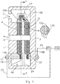
- Figure 1 shows a schematic cross-section of an apparatus for removal of ions according to an embodiment, which comprises two capacitive electrode stacks of first electrodes and second electrodes separated by spacers 11.
- the apparatus may have a housing comprising a first housing part 1 and a second housing part 3 made of a relatively hard material e.g. a hard plastic.
- a relatively hard material e.g. a hard plastic.
- Adhesive, seals or O-rings may be used to improve the water tightness of the housing.
- the housing is provided with a water inlet 7 and a water outlet 9. During ion removal from the water, the water will flow from the inlet 7 to the outlet 9 through the spacers 11 which separates the first electrode and the second electrode from each other.
- the current collectors of the electrodes of two different stacks are clamped together inside the housing. In principle the current collectors can be clamped either inside or outside the housing. Nevertheless, clamping the current collectors inside the housing may have the advantage that stacks can be placed electrically in series without the need to make holes in the housing which helps to provide a water leakage free apparatus.
- anions in the water flowing through the spacer 11 are attracted to the first electrode and cations are attracted to the second electrode.
- the ions (anions and cations) can be removed from the water flowing through the spacer 11.
- the electrical potential difference can also be created by e.g. applying a positive voltage to the first electrode (the anode) 13 and a lower positive voltage to the second electrode (cathode) 15. Also in this way the ions (anions and cations) can be removed from the water flowing through the spacer 11.
- the two capacitive electrode stacks are electrically placed in series, whereas the flow paths, which are determined by the spacers 11 are placed parallel, which means that the water may flow from the water inlet 7 to the water outlet 9 via any of the flow path of either the first or the second stack, which is placed in the same housing.
- the electrical potential differences between the first and second electrode of the first capacitive electrode stack may be rather low, for example lower than 2 Volt, preferably lower than 1,7 Volt and even more preferably lower than 1,4 Volt.
- the advantage of placing FTC stacks electrically in series is that the potential difference over multiple capacitive electrode stacks may be higher than that between the first and the second electrode.
- the potential difference over two capacitive electrode stacks A and B, provided with a first and second electrode 13A, 13B, 15A, 15B and a spacer 11, which are electrically connected in series may be twice as high than the potential difference over one single capacitive electrode stack or two capacitive electrode stacks A and B which are placed in a parallel electrical circuit.
- the current collectors of the first electrode 13A of a first capacitive electrode stack may be connected to an electrical power source PS for example and the current collector of the second electrode 15A of the first capacitive electrode stack may be connected to the current collector of the first electrode 13B of the second capacitive electrode stack.
- the connection may be directly, and may, for example, be accomplished by clamp 17, which may preferentially be made from a non-electrically conductive material since its function is to press the conductive current collectors of the second and first electrode 15A, 13B together so that the current is directly transported between the two current collectors.
- clamp 17 may be made from an electrically conductive material or may contain parts that are electrically conductive.
- the second electrode 15A of a first capacitive electrode stack may substantially have the same potential as the first electrode 13B of the second capacitive electrode stack.
- the current collectors of the second electrode 15B may also be connected to the electrical power source PS in order to complete the electrical circuit.
- the current collectors of the first electrode 13A are clamped between clamp portions 19.
- the clamp portions 19 may be made from plastic, but could also be made from carbon, for example graphite blocks.
- the clamp portions 19 may be provided with a ratchet mechanism to secure the clamp portions 19 with respect to each other and to optimize the contact surface between the current collector 13A and the clamp portions 19 to optimize electrical conductivity.
- two clamp portions 19 may be pressed against multiple current collectors of the first electrode 13A so as to press the current collectors together and provide an electrical connection, subsequently an adhesive may be used to permanently fix the clamp portions 19 with the current collectors in a watertight manner.
- a screw 21 may be used to press the current collectors 13 together with the clamp portions 19 and at the same time avoiding water metal contact of the connector.
- a screw 21 may be used to press the current collectors 13 together with the clamp portions 19 and at the same time avoiding water metal contact of the connector.
- the contact surface of the current collector and the connector of the same or similar material, for example carbon.
- An advantage of carbon is that it does not corrode in the water and that it is relatively cheap compared to other non-corrosive materials and metals.
- the pressure to clamp the current collector onto the connector may be at least 0.1 Bar, preferably at least 0.5 Bar and less than 15 Bar preferably less than 10 Bar and most preferably less than 5 Bar.
- the connector 18 may be glued against the housing so as to avoid contact of the water in the housing with the screw 21 which may be made out of metal. In this way corrosion of the screw may be prevented.
- the current collector of the second electrode 15B of the second stack may be connected to the power source PS with a second connector 20.
- the potential difference delivered by the power source PS between the current collectors of the first electrode 13A of the first capacitive electrode stack via first cable 23 and the current collector of the second electrode 15B of the second capacitive electrode stack via second cable 22 may be, for example lower than 4 Volt, preferably lower than 3,4 Volt and even more preferably lower than 2,8 Volt.
- a potential problem of the relatively high potential difference between the first and second connector, 18, 20 may be a potential leak current between the first and the second connector. This may be prevented by placing an insulator between the two connectors. This insulator 24 may also be placed between the two connectors as well as the first and second stack. The insulator 24 may be an insulator to prevent electrical and/or ionic transport.
- the applied potential difference between the first and second connector, 18, 20 may be increased or even doubled, whereas at the same time the current through the cables 22, 23 may be reduced by as much as 50%.
- the energy efficiency of the FTC apparatus may therefore be improved and the need for very thick expensive cables may be reduced.
- cheaper PS may be used that transport less current at higher voltages.
- the potential difference as delivered by the PS may be equally divided over the first and second capacitive electrode stack A, B.
- the potential difference between the first electrode 13A and second electrode 15A of the first capacitive electrode stack A may be substantially the same as the potential difference between the first electrode 13B and second electrode 15B of the second capacitive electrode stack B.
- This potential difference may for example be lower than 2 Volt, preferably lower than 1,7 Volt and even more preferably lower than 1,4 Volt.
- a feed through or opening may be provided through the housing at a position where the first and second connector 18, 20 are positioned against the housing 1,3.
- the feed through may be provided with a metal screw 21 on which the cable 23 may be connected to the electrical power source PS.
- the power source PS may be controlled by controller CN to control the operation of the apparatus for removal of ions.
- the electrodes may be made substantially metal free to keep them corrosion free in the wet interior of the housing and at the same time cheap enough for mass production.
- the electrodes may be produced from a current collector 13A, B, 15A, B provided with a substantially metal free electrically conductive high surface area layer, which may contain activated carbon, carbon nanotubes, carbon aerogels, carbon black and/or graphene on both sides which are in contact with the water.
- the high surface area layer may be provided as a coating onto the current collector or as a separate film.
- a high surface area layer is a layer with a high surface area in square meter per weight of layer material e.g.>500m 2 /gr.
- the electrodes may be regenerated by reducing or even reversing the potential difference and discharging the electrical charge on the electrodes. This may result in the release of ions from the electrodes into the water flowing through the spacer.
- the increased ion content in the water in the spacer can be flushed out of the spacer. Once most ions are released from the electrodes and the water with increased ion content is flushed out of the spacer the electrodes are regenerated and can be used again for attracting ions.
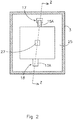
- Figure 2 discloses the cross-section along line Y-Y of the apparatus of figure 1 . It shows the clamp 17 clamping the current collectors of the first and second electrode 15A and 13B (see figure 1 ).
- the housing is provided with a space 25 for allowing water to flow around the electrodes and the spacers 11 and a second passage 27 for allowing water to collect from all the spacers 11 and flow through the outlet 9 (of figure 1 ).
- the connector 18 for connecting the current collector of the first electrode 13A is also shown.
- Figure 1 is a cross section along the line Z-Z of figure 2 .
- FIG. 3 shows a schematic three dimensional figure of an apparatus for removal of ions according to a further embodiment with 12 capacitive electrode stacks A, B, C , D...
- Each capacitive electrode stack A, B, C , D... being provided with a first electrode 13A, 13B, 13C, 13D, Vietnamese and second electrode 15A, 15B, 15C, 15D,....
- the capacitive electrode stacks are provided with an opening 27 for allowing water to enter or exit the capacitive electrode stacks.
- a first group 31 of capacitive electrode stacks A... F is connected in series and a second group 33 of capacitive electrode stacks G... L is also connected in series.
- the potential difference that may be applied between the first electrode 13A of the first capacitive electrode stack A and the second electrode 15F of the last capacitive electrode stack F of the first group may be 6 times the potential difference of a single capacitive electrode stack.
- the potential difference between the first electrode 13A of the first stack A and the second electrode 15F may therefore be for example lower than 12 Volt, preferably lower than 9,4 Volt and even more preferably lower than 8,4 Volt.
- Clamps (not shown) may be used to press the current collector of a second electrode 15A to a current collector of a first electrode 13B.
- FIG. 4 depicts a connector according to an embodiment.
- the connector 41 may be used for connecting a current collector of the apparatus for removal of ions to a power source with a cable or lead 43.
- the connector 41 may be provided with a closing off portion or contact member 47 to be placed in the housing for closing of an opening in the housing of the apparatus.
- the connector 41 may be provided with a connector surface or contact face 45 defined in a head 46 of a contact portion adjacent to the interior of the housing which may be pressed against the current collector to provide an electrical contact.
- the closing off portion or contact member 47 of the connector 41 may be provided with carbon such as graphite so as to avoid corrosion and for providing a good electrical contact with the carbon current collector of the electrodes.
- the connector 41 may be provided with a flexible material or seal 49 for providing a watertight connection with the housing.
- the seal 49 may be an o-ring, for example made of rubber to provide a water tight connection with the housing.
- the cable or lead 43 may be provided in a connector portion having a neck 42 extending from the head in a direction away from the contact face and having a receptacle at a dry surface 48 of the connector portion so as to avoid corrosion of the cable or lead 43.
- the lead or cable 43 may be engaged with the neck of the connector portion and is capable of directing an electrical current to the contact member via the head.
- the contact portion is configured to engage with the stack so that the contact member is in electrical communication with the stack.
- the contact portion may be substantially cylindrical and may define the contact face 45.
- the perimeter of the contact face may form an arcuate rim.
- the contact portion may include a recess inward of the perimeter and a protrusion extending from the recess that terminates substantially coplanar with the rim.
- the contact face and the protrusion may be substantially cylindrical.
- the housing further may have a recess proximate to the opening, and the contact portion may be seated in the recess.
- the connector or contact member 47 is press fit or adhered to the opening.
- a seal portion may be defined by at least one of the head and the neck such that the seal portion establishes a hydraulic seal between the seal portion and a mount into which the electrical connector is seated during operation.
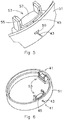
- Figure 5 depicts the connector of figure 4 provided in a ring 51 of the housing.
- the ring is provided with a connector clamp 53 for clamping the electrode against the surface 45 of the connector.
- the connector clamp 53 may be provided with a fixed part or protrusion member 55 which is extending from an interior surface of the housing and may comprise a pair of arms.
- the connector clamp 53 may be made from plastic e.g. polyethylene, polypropylene or polyvinylchloride. By making the connector clamp 53 from plastic the connector clamp may press the plurality of current collectors onto the contact surface without being sensitive to corrosion. Non-plastic connector clamps may be sensitive to corrosion because there may be water surrounding the connector clamp as well as electrical currents.
- the connector clamp may also be provided with a movable part or bridge 57 which is moveable along the pair of arms to adjust a pressure applied to the plurality of current collectors between the bridge 57 and the contact portion.
- a ratchet mechanism may be provided between fixed parts 55 and movable part 57 .
- the ratchet mechanism may comprise a surface with saw teeth which allows movement of the movable portion 55 in the direction of the connector but blocks movements of the movable portion 57 in opposite direction.
- the electrode may be provided in between the moveable portion 57 and the contact surface 45, by pressing the moveable portion 57 against the electrode and against the connector surface 45 a good connection will be provided between the electrode and the cable 43.
- Figure 6 shows a full ring 51 for the housing with two connectors 41.
- the contact surface may define a contact face having a contact plane and the current collector of the electrode may be provided with an electrode plane which may be substantially parallel to the contact plane.
- the opening 50 provided in the ring 51 of the housing may define an elbow passage having a first portion extending substantially perpendicular to a longitudinal axis of the housing and a second portion extending substantially parallel to the longitudinal axis.
- the closing off portion or contact member 47 may be seated in the second portion.
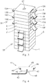
- FIG. 7 depicts the capacitive electrode stack of figure 3 wherein capacitive electrode stack A, B are provided with a tray 71A, 71B.
- the tray 71A, 71B may improve manufacturability because it may protect the electrodes during assembling of the capacitive electrode stacks in the housing.
- the tray 71 may help in aligning the electrodes and or the spacer.
- the tray may electrically and/or ionically insulate one capacitive electrode stack from another capacitive electrode stack and counteracting leak currents.
- the capacitive electrode stacks may be clamped between a bottom plate 73 and a pressure plate 75.
- a rod 77 may be provided through the opening 27 of the stacks and a nut may be provided which in cooperation with a thread on the rod may press the pressure plate 75 on the capacitive electrode stacks.
- water may be flushed through the spacer along the electrodes. Flushing the stacks with water may comprise flowing water through the stacks with a pressure of between 0,5 and 10 Bar, preferably between 1 and 5 Bar and most preferably between 2 and 4 Bar.
- Flushing helps to remove any loose material out of the spacer and/or the membranes and/or the electrodes before the pressure is applied and after flushing the capacitive electrode stack will be compressed and the capacitive electrode stacks will be fixed in the housing.
- the capacitive electrode stacks may be fixated permanently. By exerting a force on the capacitive electrode stacks so as to compress the first and second electrode and the spacer the electrical resistivity may be decreased which may make the apparatus more efficient. It is important that the electrical resistivity is substantially equal for every capacitive electrode stack because otherwise the voltage is not equally divided over the individual capacitive electrode stacks.
- the stacks may be compressed with pressure of less than 5 Bar, preferably less than 2 Bar, more preferably between 1 Bar and 0,5 Bar.
- the bottom plate 73 may form a part of the housing of the apparatus for removing ions.
- the electrode 13G may be provided in between the moveable portion 57 and the closing off portion 47 of the connector clamp 53 to be electrically connected to the cable 43.
- a contact member may be seated in the base member or bottom plate 73 to define a contact portion and a connector portion extending from the contact portion.
- a lead may be engaged with the connector portion and capable of directing an electrical current to the contact member.
- a protrusion member may be extending from the base member or bottom plate 73 adjacent to the contact member.
- a compression member (similar as the design of figure 5 ) may be configured to selectively engage the protrusion member at a plurality of positions relative to the contact member such that the compression member may be adjusted to compress a current collector of the electrode between the compression member and the contact member.
- the compression member may include a resilient arm having a first interlocking member; and the protrusion member may include a second interlocking member; the first interlocking member and the second interlocking member are configured to selectively engage such that first interlocking member of the compression member may be restrained relative to the contact member by the second interlocking member of the protrusion member.
- the first interlocking member may define a plurality of ramps and the second interlocking member may define a plurality of inverse ramps. The plurality of ramps and the plurality of inverse ramps may engage to inhibit separation of the protrusion member and the compression member.
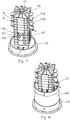
- a first housing portion e.g. a round pipe section 81 is provided to the bottom plate 73 and the ring 51 of figure 6 is located on top of the section 81.
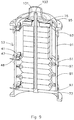
- Figure 9 shows a cross section of the apparatus of figure 3 to 7 after a second round pipe section 91 is provided on top of the ring 51, a second ring 93 is provided to the pipe section 91 and a top dome 95 is provided to the apparatus.
- the housing may be made water tight by providing flexible member 97 for example a rubber o-ring in between the housing portion and the ring 51 or between the housing portion 81 and the bottom plate 73.
- the dome opening 101 in the top dome 95 allows for water intake for example from a water pipe whereas opening 103 may be used for the water outlet.
- the dome opening 101 may also be used for maintenance of the stacks. For example a socket wrench may be allowed access through the dome opening 101 to tighten a nut cooperating with a threat provided to the rod 77.
- the capacitive electrode stacks may be compressed between the bottom plate 73 and the pressure plate 75.
- water may be flushed through the spacer along the electrodes. Flushing helps to remove any loose material out of the spacer and/or the membranes and/or the electrodes, after which the capacitive electrode stack will be compressed.
- the dome opening 101 in the tope dome 95 allows for compressing the stack while the housing is filled with water. Also the dome opening 101 allows for the pressure to be adjusted at a later stage for example during installation of the apparatus or during maintenance. Further the connector 41 located in an opening 48 in the ring 51 is shown.
- FIG. 10a discloses a pressure plate 75 according to a second embodiment.
- the pressure plate 75 is provided with a base 105 and a top portion 107.
- the top portion is provided with an opening 103 for allowing water to exit the stacks.
- Figure 10b discloses how the pressure plate 75 according to the second embodiment may be used to compress the capacitive electrode stacks together.
- a compression member for example a nut like object 109 may be accessed through the dome opening 101 to be tightened by rotating the nut like object with respect to the top dome 95.
- the nut like object 109 may be provided with an external thread 111 to cooperate with an internal thread 113 provided to the top dome 95. By rotating the nut like object 109 the capacitive electrode stacks may be compressed between the bottom plate 73 and the pressure plate 75.
- the nut like object 109 may be provided with holes for allowing water to pass through and for providing grip to rotate the nut like object 109. In the centre of the nut like object there is provided a hole in which the top portion 107 of the pressure plate 75 rotably fits.
- the pressure plate 105 may be provided with an interface between the housing and the pressure plate to inhibit a rotation of the pressure plate 105 relative to the housing.
- the interface may have a projection extending from one of the pressure plate and the housing; and a receiver formed in the other of the one of the pressure plate and the housing to inhibit a rotation.
- the top portion may define an annular lip 110 and the compression member may define an end face; and the end face of the compression member may engage the annular lip 110 of the top portion to compress the stack.
- the top dome 95 which is dome shaped may include a neck that extends into the interior. Internal threads may be formed on an interior surface of the neck; and external threads may be formed on an exterior surface of the compression member.
- the internal threads and the external threads are configured to engage, such that rotation of the compression member around the longitudinal axis may move the compression member along a longitudinal axis of the housing.
- a longitudinal slit, receiver or a slot may be formed in the neck and a radial tab 108 may be extending from the top portion 107 wherein the longitudinal slit and the radial tab are configured to interface, such that rotation of the pressure plate 75 relative to the housing is inhibited.
- FIG 11a shows a top view of a tray 113a for use in an embodiment.
- the tray 113a may comprise a main surface 115 for receiving a capacitive electrode stack.
- the tray 113a may be provided with opening 117 as an alignment feature, which may be used to slide the tray along the rod 77 (See figure 7 ) and for providing water to, or removing it from the interior of the capacitive electrode stack.
- the opening 117 may be constructed and arranged to cooperate with the rod 77, for example the size of the opening and the rod 77 may be substantially matching.
- the tray 113a may be provided with additional alignment features for alignment with the capacitive electrode stack, the rod, the housing, and/or other trays.
- Alignment features such as for example protrusion 119 may be used to align the tray 113a with the housing, or keep it at a constant distance of the housing.
- Another example of an alignment features may be tab 121 provided with teeth and provided to the first tray 113a to interlock the tray with a second tray positioned on top of the first tray 113a.
- Surrounding the opening 117 there may be provided as alignment features a first and second pillar structure 123a and 123b respectively, both pillar structures may be provided with pillars and holes.
- the pillars 125 of the first pillar structure 123a may align with the holes 127 of a second pillar structure provided to a second tray 113b (See figure 11b ).
- the tabs 121 with teeth of the first tray 113a may protrude through an opening in the second tray 113b and the teeth of the first tray may interlock with an edge of the opening of the second tray 113b.
- a spring 129 (See figure 11c ) may be provided to the tab 121 of the second tray 113b to press the teeth (not shown) against the edge 131.
- Figure 11d shows how the teeth of the tab 121 interlock with second tray 113b.
- a first electrode 133 is shown the electrode is provided with a first current collector 135 and is positioned within the tray and is aligned by the alignment features of the second tray 113b. The first current collector 135 is protruding outside the second tray 113b so that it may be connected to other current collectors.
- the second tray 113b may be provided with an opening 137 which may interlock with a clamp (not shown) which clamps the first current collector of the second tray 113b to the second current collector of another tray.
- the trays may function as an electrical insulator between capacitive electrode stacks. By interlocking a number of trays each provided with a capacitive electrode stack and by connecting the current collectors to each other the capacitive electrode stack may be assembled together. Subsequently the capacitive electrode stacks may be put into a housing and flushed with water. After flushing the capacitive electrode stacks the stacks may be compressed by rotating the nut like object 109 of figure 10 and the capacitive electrode stacks may be compressed between the bottom plate 73 and the pressure plate 75.
Description
- The invention relates to an apparatus for removal of ions provided with a plurality of capacitive electrode stacks, each electrode stack comprising:
- a plurality of first electrodes provided with a plurality of first current collectors;
- a plurality of second electrodes provided with a plurality of second current collectors; and,
- a spacer between the first and second electrodes for allowing water to flow in between the electrodes.
- In recent years one has become increasingly aware of the impact of human activities on the environment and the negative consequences this may have. Ways to reduce, reuse and recycle resources are becoming more important. In particular, clean water is becoming a scarce commodity. Therefore, various methods and devices for purifying water have been published.
- A method for water purification is by capacitive deionisation, using an apparatus provided with a flow through capacitor (FTC) for removal of ions in water. The FTC functions as an electrically regenerable cell for capacitive deionisation. By charging electrodes, ions are removed from an electrolyte and are held in electric double layers at the electrodes. The electrodes may be charged with a voltage between 0,5 to 2 Volts. The electrodes may be (partially) electrically regenerated to desorb such previously removed ions without adding chemicals.
- The apparatus for removal of ions comprises one or more pairs of spaced apart electrodes (a cathode and an anode) and a spacer, separating the electrodes and allowing water to flow between the electrodes. The electrodes are provided with current collectors or backing layers that are generally adjacent to or very near the electrodes and a material to store the ions. Current collectors are electrically conductive and transport charge in and out of the electrodes.
- The apparatus may be provided with a housing comprising a water inlet for letting water into the housing and a water outlet for letting water out of the housing. In the housing of the apparatus for removal of ions the layers of electrodes and spacers are stacked in a "sandwich" fashion by compressive force, normally by mechanical fastening.
- A problem with the apparatus for removal of ions is that the charging voltages may be low causing high electrical currents within the apparatus which may lead to increased energy loss or which may require the use of thick expensive metal connectors, or expensive power supplies that may handle high currents at low voltage.
-
WO01 13389 A1 US5 748437 describe flow-through capacitors with stacks of electrodes. - It is an object of the invention to provide an improved apparatus for removal ions.
- Accordingly, the present invention provides an apparatus for removal of ions as defined in the appended claims
- By connecting the plurality of second current collectors of a first of the plurality of capacitive electrode stacks electrically to the plurality of first current collectors of a second of the plurality of capacitive electrode stacks the electrical currents in the current collectors of a first of the plurality of capacitive electrode stacks may be substantially the same as the electrical currents in the current collectors of a second of the plurality of capacitive electrode stacks, whereas the applied voltages will be divided over the plurality of current collectors of the first and second of the plurality of capacitive electrode stacks. This allows for an operation of the apparatus for removal of ions at higher voltages, whereby the electrical currents may be kept relatively low.
- The plurality of second current collectors of the second of the plurality of capacitive electrode stacks are electrically connected to the plurality of first current collectors of a third of the plurality of capacitive electrode stacks.
- The apparatus is provided with a housing, the apparatus comprising:
- a water inlet for water entering an interior of the housing;
- a water outlet for letting water out of the interior of the housing and the plurality of second current collectors of the first of the plurality of capacitive electrode stacks, which are electrically connected to the plurality of first current collectors of the second of the plurality of capacitive electrode stacks within the same housing.
- The plurality of first and second current collector are directly electrically connected by pressing them against each other.
- The apparatus is provided with a clamp to press the plurality of current collectors against each other to electrically connect the plurality of first and second current collectors.
- The clamp may be of a non metal material. The current collectors may be metal free. The current collectors may comprise carbon, such as e.g. graphite to conduct an electrical charge.
- The apparatus may be provided with a first power connector to connect the plurality of first current collectors of the first stack with a power supply.
- The apparatus may be provided with a second power connector to connect the plurality of second current collectors of the last of the plurality of stacks with a power supply.
- The power connector may be connected in series with the plurality of first current collectors of the first of the plurality of capacitive electrode stacks and with the plurality of second current collectors of a last of the plurality of capacitive electrode stacks.
- The power connector may be provided with a metal and a carbon portion.
- The apparatus may comprise a power connector clamp for pressing the current collectors against the carbon portion of the power connector.
- An insulator may be provided between each capacitive electrode stack in order to electrically insulate the stacks from each other. The insulator may comprise a tray for holding the stack.
- A second insulator may be provided substantially surrounding the current collectors so as to electrically insulate the current collectors.
- The first current collectors of the plurality of first current collectors of the individual stacks are electrically connected with each other in parallel.
- The first current collectors of the plurality of first current collectors are electrically connected by clamping them together.
- The apparatus is provided with a housing, the apparatus comprising:
- a water inlet for water entering an interior of the housing;
- a water outlet for letting water out of the interior of the housing and the power connector providing an electrical connection between the current collectors and the power source outside of the housing.
- The second current collectors of the first of the plurality of capacitive electrode stacks are directly electrically connected to the first current collectors of the second of the plurality of capacitive stacks.
- The plurality of current collectors within the electrode stack are electrically connected in parallel.
- According to a further embodiment of the invention an apparatus for removal of ions may be provided with a plurality of electrode stacks, each electrode stack comprising:
- a plurality of first electrodes provided with a plurality of first current collectors;
- a plurality of second electrodes provided with a plurality of second current collectors; and,
- a spacer between the first and second electrodes for allowing water to flow in between the electrodes, wherein the apparatus comprises a power connector for connecting a power source to the plurality of capacitive electrode stacks in electrical serial connection with each other and the resistivity in each of the capacitive electrode stacks is substantially equal so as to divide the potential difference as applied by the power source substantially equally over all capacitive electrode stacks.
- The apparatus may be provided with a housing, the apparatus comprising:
- a water inlet for water entering an interior of the housing;
- a water outlet for letting water out of the interior of the housing and the capacitive electrode stacks are serially connected within the housing.
- The electrical current going through the second electrode of the first capacitive electrode stack may be equal to the electrical current going into the first electrode of the second capacitive electrode stack.
- The capacitive electrode stacks that are in electrical serial connection with each other may be placed in the same housing
The plurality of second current collectors of the first of the plurality of capacitive electrode stacks may be directly connected to the plurality of first current collectors of the second of the plurality of capacitive electrode stacks. - The apparatus may comprise a pressure device to provide compression of the stacks such that the pressure on each of the stacks is equal.
- These and other aspects, features and advantages will become apparent to those of ordinary skill in the art from reading the following detailed description and the appended claims. For the avoidance of doubt, any feature of one aspect of the present invention may be utilised in any other aspect of the invention. It is noted that the examples given in the description below are intended to clarify the invention and are not intended to limit the invention to those examples per se. Similarly, all percentages are weight/weight percentages unless otherwise indicated. Numerical ranges expressed in the format "from x to y" are understood to include x and y. When for a specific feature multiple preferred ranges are described in the format "from x to y", it is understood that all ranges combining the different endpoints are also contemplated.
- Embodiments of the invention will be described, by way of example only, with reference to the accompanying schematic drawings in which corresponding reference symbols indicate corresponding parts, and in which:
-
Figure 1 shows a schematic cross-section of an apparatus for removal of ions according to an embodiment; -
Figure 2 shows a schematic cross-section along the line Y-Y of the apparatus offigure 1 ; -
Figure 3 shows a schematic three dimensional figure of an apparatus for removal of ions according to a further embodiment; -
Figure 4 depicts a connector according to an embodiment; -
Figure 5 depicts the connector offigure 4 provided in a ring of a housing; -
Figure 6 shows a full ring for the housing of an apparatus for removing ions with two connectors offigure 4 ; -
Figure 7 depicts the stack offigure 3 wherein stack A, B are provided in a tray; -
Figure 8 depicts the apparatus after a first housing portion and the ring offigure 5 is provided; -
Figure 9 shows a cross section of the apparatus offigure 3 to 7 ; -
Figures 10a to 10b disclose a pressure plate according to a second embodiment; and, -
Figures 11a to 11d show a top view of atray 113a for use in an embodiment. -
Figure 1 shows a schematic cross-section of an apparatus for removal of ions according to an embodiment, which comprises two capacitive electrode stacks of first electrodes and second electrodes separated by spacers 11. The apparatus may have a housing comprising a first housing part 1 and asecond housing part 3 made of a relatively hard material e.g. a hard plastic. By pressing the first and second housing parts onto each other, for example with a bold and nut (not shown) the housing may be made water tight. Adhesive, seals or O-rings may be used to improve the water tightness of the housing. - The housing is provided with a
water inlet 7 and a water outlet 9. During ion removal from the water, the water will flow from theinlet 7 to the outlet 9 through the spacers 11 which separates the first electrode and the second electrode from each other. In the example the current collectors of the electrodes of two different stacks are clamped together inside the housing. In principle the current collectors can be clamped either inside or outside the housing. Nevertheless, clamping the current collectors inside the housing may have the advantage that stacks can be placed electrically in series without the need to make holes in the housing which helps to provide a water leakage free apparatus. By creating an electrical potential difference between the first and second electrode, for example by applying a positive voltage to the first electrode (the anode) 13 and a negative voltage to the second electrode (cathode) 15, anions in the water flowing through the spacer 11 are attracted to the first electrode and cations are attracted to the second electrode. In this way the ions (anions and cations) can be removed from the water flowing through the spacer 11. The electrical potential difference can also be created by e.g. applying a positive voltage to the first electrode (the anode) 13 and a lower positive voltage to the second electrode (cathode) 15. Also in this way the ions (anions and cations) can be removed from the water flowing through the spacer 11. In the example offigure 1 the two capacitive electrode stacks are electrically placed in series, whereas the flow paths, which are determined by the spacers 11 are placed parallel, which means that the water may flow from thewater inlet 7 to the water outlet 9 via any of the flow path of either the first or the second stack, which is placed in the same housing. - The electrical potential differences between the first and second electrode of the first capacitive electrode stack may be rather low, for example lower than 2 Volt, preferably lower than 1,7 Volt and even more preferably lower than 1,4 Volt. The advantage of placing FTC stacks electrically in series is that the potential difference over multiple capacitive electrode stacks may be higher than that between the first and the second electrode. For example, the potential difference over two capacitive electrode stacks A and B, provided with a first and
second electrode first electrode 13A of a first capacitive electrode stack may be connected to an electrical power source PS for example and the current collector of thesecond electrode 15A of the first capacitive electrode stack may be connected to the current collector of thefirst electrode 13B of the second capacitive electrode stack. The connection may be directly, and may, for example, be accomplished byclamp 17, which may preferentially be made from a non-electrically conductive material since its function is to press the conductive current collectors of the second andfirst electrode second electrode 15A of a first capacitive electrode stack may substantially have the same potential as thefirst electrode 13B of the second capacitive electrode stack. The current collectors of the second electrode 15B may also be connected to the electrical power source PS in order to complete the electrical circuit. - The current collectors of the
first electrode 13A are clamped betweenclamp portions 19. Theclamp portions 19 may be made from plastic, but could also be made from carbon, for example graphite blocks. Theclamp portions 19 may be provided with a ratchet mechanism to secure theclamp portions 19 with respect to each other and to optimize the contact surface between thecurrent collector 13A and theclamp portions 19 to optimize electrical conductivity. To make the first connector, twoclamp portions 19 may be pressed against multiple current collectors of thefirst electrode 13A so as to press the current collectors together and provide an electrical connection, subsequently an adhesive may be used to permanently fix theclamp portions 19 with the current collectors in a watertight manner. Alternatively ascrew 21 may be used to press the current collectors 13 together with theclamp portions 19 and at the same time avoiding water metal contact of the connector. For a low electrical resistance it is advantageous to make the contact surface of the current collector and the connector of the same or similar material, for example carbon. An advantage of carbon is that it does not corrode in the water and that it is relatively cheap compared to other non-corrosive materials and metals. - The pressure to clamp the current collector onto the connector may be at least 0.1 Bar, preferably at least 0.5 Bar and less than 15 Bar preferably less than 10 Bar and most preferably less than 5 Bar. The
connector 18 may be glued against the housing so as to avoid contact of the water in the housing with thescrew 21 which may be made out of metal. In this way corrosion of the screw may be prevented. In a similar way the current collector of the second electrode 15B of the second stack may be connected to the power source PS with asecond connector 20. The potential difference delivered by the power source PS between the current collectors of thefirst electrode 13A of the first capacitive electrode stack viafirst cable 23 and the current collector of the second electrode 15B of the second capacitive electrode stack viasecond cable 22 may be, for example lower than 4 Volt, preferably lower than 3,4 Volt and even more preferably lower than 2,8 Volt. - A potential problem of the relatively high potential difference between the first and second connector, 18, 20 may be a potential leak current between the first and the second connector. This may be prevented by placing an insulator between the two connectors. This
insulator 24 may also be placed between the two connectors as well as the first and second stack. Theinsulator 24 may be an insulator to prevent electrical and/or ionic transport. By placing the capacitive electrode stacks electrically in series, the applied potential difference between the first and second connector, 18, 20 may be increased or even doubled, whereas at the same time the current through thecables - By assuring that the electrical resistance of the first and second capacitive electrode stacks A and B are substantially the same, the potential difference as delivered by the PS may be equally divided over the first and second capacitive electrode stack A, B. As a consequence the potential difference between the
first electrode 13A andsecond electrode 15A of the first capacitive electrode stack A may be substantially the same as the potential difference between thefirst electrode 13B and second electrode 15B of the second capacitive electrode stack B. This potential difference may for example be lower than 2 Volt, preferably lower than 1,7 Volt and even more preferably lower than 1,4 Volt. - A feed through or opening may be provided through the housing at a position where the first and
second connector housing 1,3. The feed through may be provided with ametal screw 21 on which thecable 23 may be connected to the electrical power source PS. The power source PS may be controlled by controller CN to control the operation of the apparatus for removal of ions. - The electrodes may be made substantially metal free to keep them corrosion free in the wet interior of the housing and at the same time cheap enough for mass production. The electrodes may be produced from a
current collector 13A, B, 15A, B provided with a substantially metal free electrically conductive high surface area layer, which may contain activated carbon, carbon nanotubes, carbon aerogels, carbon black and/or graphene on both sides which are in contact with the water. The high surface area layer may be provided as a coating onto the current collector or as a separate film. A high surface area layer is a layer with a high surface area in square meter per weight of layer material e.g.>500m2/gr. - If the electrodes are saturated with ions the electrodes may be regenerated by reducing or even reversing the potential difference and discharging the electrical charge on the electrodes. This may result in the release of ions from the electrodes into the water flowing through the spacer. The increased ion content in the water in the spacer can be flushed out of the spacer. Once most ions are released from the electrodes and the water with increased ion content is flushed out of the spacer the electrodes are regenerated and can be used again for attracting ions.
-
Figure 2 discloses the cross-section along line Y-Y of the apparatus offigure 1 . It shows theclamp 17 clamping the current collectors of the first andsecond electrode figure 1 ). The housing is provided with aspace 25 for allowing water to flow around the electrodes and the spacers 11 and asecond passage 27 for allowing water to collect from all the spacers 11 and flow through the outlet 9 (offigure 1 ). Theconnector 18 for connecting the current collector of thefirst electrode 13A is also shown.Figure 1 is a cross section along the line Z-Z offigure 2 . -
Figure 3 shows a schematic three dimensional figure of an apparatus for removal of ions according to a further embodiment with 12 capacitive electrode stacks A, B, C , D... Each capacitive electrode stack A, B, C , D... being provided with afirst electrode second electrode opening 27 for allowing water to enter or exit the capacitive electrode stacks. Afirst group 31 of capacitive electrode stacks A... F is connected in series and asecond group 33 of capacitive electrode stacks G... L is also connected in series. The potential difference that may be applied between thefirst electrode 13A of the first capacitive electrode stack A and thesecond electrode 15F of the last capacitive electrode stack F of the first group may be 6 times the potential difference of a single capacitive electrode stack. The potential difference between thefirst electrode 13A of the first stack A and thesecond electrode 15F may therefore be for example lower than 12 Volt, preferably lower than 9,4 Volt and even more preferably lower than 8,4 Volt. Clamps (not shown) may be used to press the current collector of asecond electrode 15A to a current collector of afirst electrode 13B. -
Figure 4 depicts a connector according to an embodiment. Theconnector 41 may be used for connecting a current collector of the apparatus for removal of ions to a power source with a cable or lead 43. Theconnector 41 may be provided with a closing off portion orcontact member 47 to be placed in the housing for closing of an opening in the housing of the apparatus. Theconnector 41 may be provided with a connector surface orcontact face 45 defined in ahead 46 of a contact portion adjacent to the interior of the housing which may be pressed against the current collector to provide an electrical contact. The closing off portion orcontact member 47 of theconnector 41 may be provided with carbon such as graphite so as to avoid corrosion and for providing a good electrical contact with the carbon current collector of the electrodes. Theconnector 41 may be provided with a flexible material or seal 49 for providing a watertight connection with the housing. Theseal 49 may be an o-ring, for example made of rubber to provide a water tight connection with the housing. The cable or lead 43 may be provided in a connector portion having aneck 42 extending from the head in a direction away from the contact face and having a receptacle at adry surface 48 of the connector portion so as to avoid corrosion of the cable or lead 43. The lead orcable 43 may be engaged with the neck of the connector portion and is capable of directing an electrical current to the contact member via the head. The contact portion is configured to engage with the stack so that the contact member is in electrical communication with the stack. The contact portion may be substantially cylindrical and may define thecontact face 45. The perimeter of the contact face may form an arcuate rim. The contact portion may include a recess inward of the perimeter and a protrusion extending from the recess that terminates substantially coplanar with the rim. The contact face and the protrusion may be substantially cylindrical. The housing further may have a recess proximate to the opening, and the contact portion may be seated in the recess. The connector orcontact member 47 is press fit or adhered to the opening. A seal portion may be defined by at least one of the head and the neck such that the seal portion establishes a hydraulic seal between the seal portion and a mount into which the electrical connector is seated during operation. -
Figure 5 depicts the connector offigure 4 provided in aring 51 of the housing. The ring is provided with aconnector clamp 53 for clamping the electrode against thesurface 45 of the connector. Theconnector clamp 53 may be provided with a fixed part orprotrusion member 55 which is extending from an interior surface of the housing and may comprise a pair of arms. Theconnector clamp 53 may be made from plastic e.g. polyethylene, polypropylene or polyvinylchloride. By making theconnector clamp 53 from plastic the connector clamp may press the plurality of current collectors onto the contact surface without being sensitive to corrosion. Non-plastic connector clamps may be sensitive to corrosion because there may be water surrounding the connector clamp as well as electrical currents. The connector clamp may also be provided with a movable part or bridge 57 which is moveable along the pair of arms to adjust a pressure applied to the plurality of current collectors between thebridge 57 and the contact portion. Betweenfixed parts 55 and movable part 57 a ratchet mechanism may be provided. For example, the ratchet mechanism may comprise a surface with saw teeth which allows movement of themovable portion 55 in the direction of the connector but blocks movements of themovable portion 57 in opposite direction. The electrode may be provided in between themoveable portion 57 and thecontact surface 45, by pressing themoveable portion 57 against the electrode and against the connector surface 45 a good connection will be provided between the electrode and thecable 43.Figure 6 shows afull ring 51 for the housing with twoconnectors 41. The contact surface may define a contact face having a contact plane and the current collector of the electrode may be provided with an electrode plane which may be substantially parallel to the contact plane. Theopening 50 provided in thering 51 of the housing may define an elbow passage having a first portion extending substantially perpendicular to a longitudinal axis of the housing and a second portion extending substantially parallel to the longitudinal axis. The closing off portion orcontact member 47 may be seated in the second portion. -
Figure 7 depicts the capacitive electrode stack offigure 3 wherein capacitive electrode stack A, B are provided with atray 71A, 71B. Thetray 71A, 71B may improve manufacturability because it may protect the electrodes during assembling of the capacitive electrode stacks in the housing. During manufacturing of one capacitive electrode stack the tray 71 may help in aligning the electrodes and or the spacer. During use of the apparatus the tray may electrically and/or ionically insulate one capacitive electrode stack from another capacitive electrode stack and counteracting leak currents. - The capacitive electrode stacks may be clamped between a
bottom plate 73 and apressure plate 75. Arod 77 may be provided through theopening 27 of the stacks and a nut may be provided which in cooperation with a thread on the rod may press thepressure plate 75 on the capacitive electrode stacks. Before pressing the pressure plate on the capacitive electrode stacks water may be flushed through the spacer along the electrodes. Flushing the stacks with water may comprise flowing water through the stacks with a pressure of between 0,5 and 10 Bar, preferably between 1 and 5 Bar and most preferably between 2 and 4 Bar. Flushing helps to remove any loose material out of the spacer and/or the membranes and/or the electrodes before the pressure is applied and after flushing the capacitive electrode stack will be compressed and the capacitive electrode stacks will be fixed in the housing. The capacitive electrode stacks may be fixated permanently. By exerting a force on the capacitive electrode stacks so as to compress the first and second electrode and the spacer the electrical resistivity may be decreased which may make the apparatus more efficient. It is important that the electrical resistivity is substantially equal for every capacitive electrode stack because otherwise the voltage is not equally divided over the individual capacitive electrode stacks. If one capacitive electrode stack operates at higher voltage than another capacitive electrode stack then the capacitive electrode stack which receives a higher voltage may become damaged due to oxidation and/or electrolysis. Therefore the pressure needs to be equally divided for all the capacitive electrode stacks. The stacks may be compressed with pressure of less than 5 Bar, preferably less than 2 Bar, more preferably between 1 Bar and 0,5 Bar. - The
bottom plate 73 may form a part of the housing of the apparatus for removing ions. Infigure 7 it is also shown how theelectrode 13G may be provided in between themoveable portion 57 and the closing offportion 47 of theconnector clamp 53 to be electrically connected to thecable 43. A contact member may be seated in the base member orbottom plate 73 to define a contact portion and a connector portion extending from the contact portion. A lead may be engaged with the connector portion and capable of directing an electrical current to the contact member. A protrusion member may be extending from the base member orbottom plate 73 adjacent to the contact member. A compression member (similar as the design offigure 5 ) may be configured to selectively engage the protrusion member at a plurality of positions relative to the contact member such that the compression member may be adjusted to compress a current collector of the electrode between the compression member and the contact member. The compression member may include a resilient arm having a first interlocking member; and the protrusion member may include a second interlocking member; the first interlocking member and the second interlocking member are configured to selectively engage such that first interlocking member of the compression member may be restrained relative to the contact member by the second interlocking member of the protrusion member. The first interlocking member may define a plurality of ramps and the second interlocking member may define a plurality of inverse ramps. The plurality of ramps and the plurality of inverse ramps may engage to inhibit separation of the protrusion member and the compression member. - In
figure 8 a first housing portion e.g. around pipe section 81 is provided to thebottom plate 73 and thering 51 offigure 6 is located on top of thesection 81. -
Figure 9 shows a cross section of the apparatus offigure 3 to 7 after a secondround pipe section 91 is provided on top of thering 51, asecond ring 93 is provided to thepipe section 91 and atop dome 95 is provided to the apparatus. The housing may be made water tight by providingflexible member 97 for example a rubber o-ring in between the housing portion and thering 51 or between thehousing portion 81 and thebottom plate 73. Thedome opening 101 in thetop dome 95 allows for water intake for example from a water pipe whereas opening 103 may be used for the water outlet. Thedome opening 101 may also be used for maintenance of the stacks. For example a socket wrench may be allowed access through thedome opening 101 to tighten a nut cooperating with a threat provided to therod 77. By tightening the nut the capacitive electrode stacks may be compressed between thebottom plate 73 and thepressure plate 75. Before compressing the pressure plate on the capacitive electrode stacks, water may be flushed through the spacer along the electrodes. Flushing helps to remove any loose material out of the spacer and/or the membranes and/or the electrodes, after which the capacitive electrode stack will be compressed. It is advantageously that thedome opening 101 in thetope dome 95 allows for compressing the stack while the housing is filled with water. Also thedome opening 101 allows for the pressure to be adjusted at a later stage for example during installation of the apparatus or during maintenance.. Further theconnector 41 located in anopening 48 in thering 51 is shown. Theclamp 53 presses the current collector of an electrode onto theconnector 41 and thereby presses the closing offbody 47 in theopening 48, thereby closing off theopening 48 for water inside the housing.Figure 10a discloses apressure plate 75 according to a second embodiment. Thepressure plate 75 is provided with abase 105 and atop portion 107. The top portion is provided with anopening 103 for allowing water to exit the stacks.Figure 10b discloses how thepressure plate 75 according to the second embodiment may be used to compress the capacitive electrode stacks together. A compression member, for example a nut likeobject 109 may be accessed through thedome opening 101 to be tightened by rotating the nut like object with respect to thetop dome 95. The nut likeobject 109 may be provided with anexternal thread 111 to cooperate with aninternal thread 113 provided to thetop dome 95. By rotating the nut likeobject 109 the capacitive electrode stacks may be compressed between thebottom plate 73 and thepressure plate 75. The nut likeobject 109 may be provided with holes for allowing water to pass through and for providing grip to rotate the nut likeobject 109. In the centre of the nut like object there is provided a hole in which thetop portion 107 of thepressure plate 75 rotably fits. Thepressure plate 105 may be provided with an interface between the housing and the pressure plate to inhibit a rotation of thepressure plate 105 relative to the housing. The interface may have a projection extending from one of the pressure plate and the housing; and a receiver formed in the other of the one of the pressure plate and the housing to inhibit a rotation. The top portion may define an annular lip 110 and the compression member may define an end face; and the end face of the compression member may engage the annular lip 110 of the top portion to compress the stack. - Before compressing the pressure plate on the capacitive electrode stacks, water may be flushed through the spacer along the electrodes to hydrate the stack. Hydrating and/or flushing helps to remove any loose material out of the spacer, after which the capacitive electrode stack will be compressed. It is advantageously that the
dome opening 101 in thetop dome 95 allows for the compression to take place because the capacitive electrode stacks may be compressed after the housing has been filled with water. Also during maintenance the compression may be adjusted via thedome opening 101. Thetop dome 95 which is dome shaped may include a neck that extends into the interior. Internal threads may be formed on an interior surface of the neck; and external threads may be formed on an exterior surface of the compression member. The internal threads and the external threads are configured to engage, such that rotation of the compression member around the longitudinal axis may move the compression member along a longitudinal axis of the housing. A longitudinal slit, receiver or a slot may be formed in the neck and a radial tab 108 may be extending from thetop portion 107 wherein the longitudinal slit and the radial tab are configured to interface, such that rotation of thepressure plate 75 relative to the housing is inhibited. -
Figure 11a shows a top view of atray 113a for use in an embodiment. Thetray 113a may comprise amain surface 115 for receiving a capacitive electrode stack. Thetray 113a may be provided withopening 117 as an alignment feature, which may be used to slide the tray along the rod 77 (Seefigure 7 ) and for providing water to, or removing it from the interior of the capacitive electrode stack. Theopening 117 may be constructed and arranged to cooperate with therod 77, for example the size of the opening and therod 77 may be substantially matching. Thetray 113a may be provided with additional alignment features for alignment with the capacitive electrode stack, the rod, the housing, and/or other trays. Alignment features such as forexample protrusion 119 may be used to align thetray 113a with the housing, or keep it at a constant distance of the housing. Another example of an alignment features may betab 121 provided with teeth and provided to thefirst tray 113a to interlock the tray with a second tray positioned on top of thefirst tray 113a. Surrounding theopening 117 there may be provided as alignment features a first andsecond pillar structure pillars 125 of thefirst pillar structure 123a may align with theholes 127 of a second pillar structure provided to asecond tray 113b (Seefigure 11b ). Thetabs 121 with teeth of thefirst tray 113a may protrude through an opening in thesecond tray 113b and the teeth of the first tray may interlock with an edge of the opening of thesecond tray 113b. A spring 129 (Seefigure 11c ) may be provided to thetab 121 of thesecond tray 113b to press the teeth (not shown) against theedge 131.Figure 11d shows how the teeth of thetab 121 interlock withsecond tray 113b. Further afirst electrode 133 is shown the electrode is provided with a firstcurrent collector 135 and is positioned within the tray and is aligned by the alignment features of thesecond tray 113b. The firstcurrent collector 135 is protruding outside thesecond tray 113b so that it may be connected to other current collectors. Thesecond tray 113b may be provided with anopening 137 which may interlock with a clamp (not shown) which clamps the first current collector of thesecond tray 113b to the second current collector of another tray. The trays may function as an electrical insulator between capacitive electrode stacks. By interlocking a number of trays each provided with a capacitive electrode stack and by connecting the current collectors to each other the capacitive electrode stack may be assembled together. Subsequently the capacitive electrode stacks may be put into a housing and flushed with water. After flushing the capacitive electrode stacks the stacks may be compressed by rotating the nut likeobject 109 offigure 10 and the capacitive electrode stacks may be compressed between thebottom plate 73 and thepressure plate 75.
Claims (10)
- An apparatus provided with a flow through capacitor for removal of ions in water provided with a plurality of capacitive electrode stacks (A, B), each capacitive electrode stack (A, B) comprising:a plurality of first electrodes (e.g. anodes during ion removal from water) provided with a plurality of first current collectors (13, 13A, 13B)), wherein first current collectors 13A of the plurality of first current collectors of the individual capacitive electrode stacks are directly electrically connected with each other in parallel between clamp portions (19);a plurality of second electrodes (e. g. cathodes during ion removal from water) provided with a plurality of second current collectors (15, 15A, 15B); and,
a spacer (11) between the first and second electrodes (13, 13A, 13B, 15, 15A, 15B) for allowing water to flow in parallel between the electrodes, wherein the plurality of second current collectors (15, 15A, 15B) of a first of the plurality of capacitive electrode stacks (A) are directly electrically connected in series to the plurality of first current collectors (13, 13A, 13B); of a second of the plurality of capacitive electrode stacks (B), wherein a clamp (17) is provided to press the plurality of first and second current collectors (13B, 15A) against each other to electrically connect the plurality of first and second current collectors (13B, 15A) in series, wherein the apparatus is provided with a housing (1,3), the apparatus comprising:a water inlet (7) for water entering an interior of the housing (1,3);a water outlet (9) for letting water out of the interior of the housing (1,3) and the plurality of second current collectors (15, 15A, 15B) of the first of the plurality of capacitive electrode stacks (A), which are electrically connected to the plurality of first current collectors (13, 13A, 13B) of the second of the plurality of capacitive electrode stacks (B) within the same housing (1,3). - The apparatus according to any of the preceding claims, wherein the plurality of second current collectors (15, 15A, 15B) of the second of the plurality of capacitive electrode stacks (B) is electrically connected to the plurality of first current collectors (13, 13A, 13B) of a third of the plurality of capacitive electrode stacks (C).
- The apparatus according to claim 1 or 2, wherein the clamp (17) is of a non metal material.
- The apparatus according to any of the preceding claims wherein the apparatus is provided with a power connector (18, 20, 41) for connection with a power supply (PS) and the stacks (A, B) are connected in series with the power connector (18, 20, 41).
- The apparatus according to claim 4, wherein the power connector (18, 20, 41) is connected in series with the plurality of first current collectors (13A) of the first of the plurality of capacitive electrode stacks (A, B) and with the plurality of second current collectors (15B) of a last of the plurality of capacitive electrode stacks (A, B).
- The apparatus according to any of claims 4 to 5, wherein the power connector (18, 20) is provided with a metal and a carbon portion.
- The apparatus according to claim 6, wherein the apparatus comprises a power connector clamp (41, 53) for pressing the current collectors against the carbon portion of the power connector.
- The apparatus according to any of the preceding claims, wherein an insulator (24) is provided between each capacitive electrode stack (A, B) in order to electrically insulate the stacks from each other.
- The apparatus according to claim 8, wherein a second insulator (24) is provided substantially surrounding the current collector so as to electrically insulate the current collector.
- The apparatus according to any of claim 4 to 9, wherein the apparatus is provided with a housing (1,3), the apparatus comprising:a water inlet (7) for water entering an interior of the housing (1,3);a water outlet (9) for letting water out of the interior of the housing (1,3) and the power connector is providing an electrical connection between the current collectors and the power source outside of the housing (1,3).
Applications Claiming Priority (2)
| Application Number | Priority Date | Filing Date | Title |
|---|---|---|---|
| NL2007598A NL2007598C2 (en) | 2011-10-14 | 2011-10-14 | Apparatus and method for removal of ions. |
| PCT/NL2012/050716 WO2013055220A1 (en) | 2011-10-14 | 2012-10-12 | Apparatus and method for removal of ions |
Publications (2)
| Publication Number | Publication Date |
|---|---|
| EP2766308A1 EP2766308A1 (en) | 2014-08-20 |
| EP2766308B1 true EP2766308B1 (en) | 2021-01-06 |
Family
ID=47116227
Family Applications (1)
| Application Number | Title | Priority Date | Filing Date |
|---|---|---|---|
| EP12780866.5A Active EP2766308B1 (en) | 2011-10-14 | 2012-10-12 | Apparatus and method for removal of ions |
Country Status (6)
| Country | Link |
|---|---|
| US (2) | US10399872B2 (en) |
| EP (1) | EP2766308B1 (en) |
| CN (1) | CN103889902B (en) |
| IN (1) | IN2014DN03329A (en) |
| NL (1) | NL2007598C2 (en) |
| WO (1) | WO2013055220A1 (en) |
Families Citing this family (9)
| Publication number | Priority date | Publication date | Assignee | Title |
|---|---|---|---|---|
| US20110056843A1 (en) | 2009-09-08 | 2011-03-10 | Patrick Michael Curran | Concentric layer electric double layer capacitor cylinder, system, and method of use |
| NL2007599C2 (en) | 2011-10-14 | 2013-04-16 | Voltea Bv | Apparatus and method for removal removal of ions. |
| NL2007598C2 (en) * | 2011-10-14 | 2013-04-16 | Voltea Bv | Apparatus and method for removal of ions. |
| US9859066B2 (en) | 2013-05-24 | 2018-01-02 | Atlantis Technologies | Atomic capacitor |
| EP2980027A1 (en) | 2014-07-29 | 2016-02-03 | Voltea B.V. | Operating an apparatus for removal of ions with warm and cold water |
| GB201603892D0 (en) * | 2016-03-07 | 2016-04-20 | Fujifilm Mfg Europe Bv | Capacitive deionisation |
| GB201603889D0 (en) * | 2016-03-07 | 2016-04-20 | Fujifilm Mfg Europe Bv | Capacitive deionisation |
| US10787378B2 (en) | 2018-05-30 | 2020-09-29 | Atlantis Technologies | Spirally wound electric double layer capacitor device and associated methods |
| CN108821398B (en) * | 2018-07-10 | 2022-02-01 | 佛山市云米电器科技有限公司 | EDR desalination system |
Citations (2)
| Publication number | Priority date | Publication date | Assignee | Title |
|---|---|---|---|---|
| US5748437A (en) * | 1990-04-23 | 1998-05-05 | Andelman; Marc D. | Fluid separation system with flow-through capacitor |
| WO2001013389A1 (en) * | 1999-08-13 | 2001-02-22 | Andelman Marc D | Flow-through capacitor, system and method |
Family Cites Families (25)
| Publication number | Priority date | Publication date | Assignee | Title |
|---|---|---|---|---|
| US4671863A (en) * | 1985-10-28 | 1987-06-09 | Tejeda Alvaro R | Reversible electrolytic system for softening and dealkalizing water |
| US5094739A (en) * | 1989-03-20 | 1992-03-10 | Kump Joseph A | Methods and apparatus for treatment of water |
| US5584981A (en) * | 1994-05-06 | 1996-12-17 | United Kingdom Atomic Energy Authority | Electrochemical deionization |
| JP4286931B2 (en) * | 1998-09-08 | 2009-07-01 | バイオソース・インコーポレーテッド | Liquid-permeable capacitor and liquid processing method using the same |
| EP1164110A1 (en) * | 2000-06-16 | 2001-12-19 | Abb Research Ltd. | Capacitor deionization apparatus |
| US6628505B1 (en) * | 2000-07-29 | 2003-09-30 | Biosource, Inc. | Flow-through capacitor, system and method |
| US6582592B2 (en) * | 2001-06-12 | 2003-06-24 | Hydrotreat, Inc. | Apparatus for removing dissolved metals from wastewater by electrocoagulation |
| WO2003009920A1 (en) * | 2001-07-25 | 2003-02-06 | Biosource, Inc. | Electrode array for use in electrochemical cells |
| US7235164B2 (en) * | 2002-10-18 | 2007-06-26 | Eksigent Technologies, Llc | Electrokinetic pump having capacitive electrodes |
| US20040129578A1 (en) * | 2003-01-07 | 2004-07-08 | Mclachlan David | Electrostatic fluid treatment apparatus and method |
| CA2611557C (en) * | 2005-06-10 | 2013-08-06 | Process Solutions, Inc. | Electrolytic cell and system for treating water |
| US20080105551A1 (en) | 2005-12-14 | 2008-05-08 | Shengxian Wang | Supercapacitor desalination devices and methods of making the same |
| US20080198531A1 (en) * | 2007-02-15 | 2008-08-21 | Lih-Ren Shiue | Capacitive deionization system for water treatment |
| US20100059378A1 (en) * | 2007-07-18 | 2010-03-11 | The Water Company Llc | Apparatus and method for removal of ions from a porous electrode that is part of a deionization system |
| US7830646B2 (en) * | 2007-09-25 | 2010-11-09 | Ioxus, Inc. | Multi electrode series connected arrangement supercapacitor |
| JP4461271B2 (en) * | 2008-03-25 | 2010-05-12 | 有限会社ターナープロセス | Portable hardness adjustment device for adjusting the hardness of drinking water |
| CN101615512B (en) * | 2008-06-24 | 2013-02-06 | 通用电气公司 | Super-capacitor device and manufacturing method thereof |
| GB0823074D0 (en) * | 2008-12-18 | 2009-01-28 | Enpar Technologies Inc | Design and method of assembly of cdi cells |
| EP2253593A1 (en) * | 2009-05-12 | 2010-11-24 | Voltea B.V. | Apparatus and method for removal of ions |
| KR20110019573A (en) * | 2009-08-20 | 2011-02-28 | 삼성전자주식회사 | Capacitive deionization device |
| KR101022257B1 (en) * | 2009-10-07 | 2011-03-21 | (주) 시온텍 | Capacitive deionization hybridized electrode having ion selectivity and module manufacturing method |
| EP2322486B1 (en) * | 2009-11-04 | 2014-01-22 | Voltea B.V. | An apparatus and method for removal of ions |
| GB0921953D0 (en) * | 2009-12-16 | 2010-02-03 | Enpar Technologies Inc | Flow-through electro static water filter |
| KR101688530B1 (en) | 2009-12-21 | 2016-12-21 | 삼성전자주식회사 | Capacitive deionization device |
| NL2007598C2 (en) * | 2011-10-14 | 2013-04-16 | Voltea Bv | Apparatus and method for removal of ions. |
-
2011
- 2011-10-14 NL NL2007598A patent/NL2007598C2/en active
-
2012
- 2012-10-12 CN CN201280050434.1A patent/CN103889902B/en active Active
- 2012-10-12 EP EP12780866.5A patent/EP2766308B1/en active Active
- 2012-10-12 IN IN3329DEN2014 patent/IN2014DN03329A/en unknown
- 2012-10-12 US US14/351,857 patent/US10399872B2/en active Active
- 2012-10-12 WO PCT/NL2012/050716 patent/WO2013055220A1/en active Application Filing
-
2019
- 2019-08-22 US US16/548,302 patent/US11168009B2/en active Active
Patent Citations (2)
| Publication number | Priority date | Publication date | Assignee | Title |
|---|---|---|---|---|
| US5748437A (en) * | 1990-04-23 | 1998-05-05 | Andelman; Marc D. | Fluid separation system with flow-through capacitor |
| WO2001013389A1 (en) * | 1999-08-13 | 2001-02-22 | Andelman Marc D | Flow-through capacitor, system and method |
Also Published As
| Publication number | Publication date |
|---|---|
| US20190382289A1 (en) | 2019-12-19 |
| WO2013055220A1 (en) | 2013-04-18 |
| US11168009B2 (en) | 2021-11-09 |
| US10399872B2 (en) | 2019-09-03 |
| NL2007598C2 (en) | 2013-04-16 |
| US20140238862A1 (en) | 2014-08-28 |
| CN103889902B (en) | 2019-05-17 |
| IN2014DN03329A (en) | 2015-06-05 |
| EP2766308A1 (en) | 2014-08-20 |
| CN103889902A (en) | 2014-06-25 |
Similar Documents
| Publication | Publication Date | Title |
|---|---|---|
| EP2766308B1 (en) | Apparatus and method for removal of ions | |
| EP2766309B1 (en) | Method of producing an apparatus for removal of ions | |
| US9096451B2 (en) | Apparatus and method for removal of ions | |
| US6413409B1 (en) | Flow-through capacitor and method of treating liquids with it | |
| US20100078327A1 (en) | Deionization apparatus, electrode module for the same and method for manufacturing the same | |
| US8968544B2 (en) | Apparatus and method for removal of ions | |
| EP1115909B1 (en) | Flow-through capacitor and method of treating liquids with it | |
| EP2460770B1 (en) | Method of producing an apparatus for removal of ions from water and an apparatus for removal of ions from water | |
| US20120125776A1 (en) | Apparatus and method for removal of ions | |
| JP3893740B2 (en) | Electrolytic capacitor type desalting apparatus and desalting method | |
| US20130153423A1 (en) | Apparatus and method for removal of ions | |
| US20130146463A1 (en) | Apparatus and method for removal of ions | |
| EP2646374B1 (en) | An apparatus for removal of ions comprising multiple stacks | |
| SE540976C2 (en) | Device for capacitive deionization of aqueous media and method of manufacturing such a device | |
| KR20150003094A (en) | Flow-electrode capacitive deionizaion apparatus using ion exchange membranes | |
| KR102237038B1 (en) | Carbon electrode filter for household water purifier |
Legal Events
| Date | Code | Title | Description |
|---|---|---|---|
| PUAI | Public reference made under article 153(3) epc to a published international application that has entered the european phase |
Free format text: ORIGINAL CODE: 0009012 |
|
| 17P | Request for examination filed |
Effective date: 20140428 |
|
| AK | Designated contracting states |
Kind code of ref document: A1 Designated state(s): AL AT BE BG CH CY CZ DE DK EE ES FI FR GB GR HR HU IE IS IT LI LT LU LV MC MK MT NL NO PL PT RO RS SE SI SK SM TR |
|
| DAX | Request for extension of the european patent (deleted) | ||
| STAA | Information on the status of an ep patent application or granted ep patent |
Free format text: STATUS: EXAMINATION IS IN PROGRESS |
|
| 17Q | First examination report despatched |
Effective date: 20170316 |
|
| 111Z | Information provided on other rights and legal means of execution |
Free format text: AL AT BE BG CH CY CZ DE DK EE ES FI FR GB GR HR HU IE IS IT LT LU LV MC MK MT NL NO PL PT RO RS SE SI SK SM TR Effective date: 20181212 |
|
| GRAP | Despatch of communication of intention to grant a patent |
Free format text: ORIGINAL CODE: EPIDOSNIGR1 |
|
| STAA | Information on the status of an ep patent application or granted ep patent |
Free format text: STATUS: GRANT OF PATENT IS INTENDED |
|
| INTG | Intention to grant announced |
Effective date: 20200323 |
|
| GRAS | Grant fee paid |
Free format text: ORIGINAL CODE: EPIDOSNIGR3 |
|
| RAP1 | Party data changed (applicant data changed or rights of an application transferred) |
Owner name: VOLTEA LIMITED |
|
| GRAA | (expected) grant |
Free format text: ORIGINAL CODE: 0009210 |
|
| STAA | Information on the status of an ep patent application or granted ep patent |
Free format text: STATUS: THE PATENT HAS BEEN GRANTED |
|
| AK | Designated contracting states |
Kind code of ref document: B1 Designated state(s): AL AT BE BG CH CY CZ DE DK EE ES FI FR GB GR HR HU IE IS IT LI LT LU LV MC MK MT NL NO PL PT RO RS SE SI SK SM TR |
|
| D11X | Information provided on other rights and legal means of execution (deleted) | ||
| REG | Reference to a national code |
Ref country code: GB Ref legal event code: FG4D |
|
| REG | Reference to a national code |
Ref country code: AT Ref legal event code: REF Ref document number: 1352169 Country of ref document: AT Kind code of ref document: T Effective date: 20210115 Ref country code: CH Ref legal event code: EP |
|
| 111Z | Information provided on other rights and legal means of execution |
Free format text: AL AT BE BG CH CY CZ DE DK EE ES FI FR GB GR HR HU IE IS IT LT LU LV MC MK MT NL NO PL PT RO RS SE SI SK SM TR Effective date: 20200804 |
|
| REG | Reference to a national code |
Ref country code: DE Ref legal event code: R096 Ref document number: 602012074035 Country of ref document: DE |
|
| REG | Reference to a national code |
Ref country code: NL Ref legal event code: FP |
|
| REG | Reference to a national code |
Ref country code: IE Ref legal event code: FG4D |
|
| REG | Reference to a national code |
Ref country code: AT Ref legal event code: MK05 Ref document number: 1352169 Country of ref document: AT Kind code of ref document: T Effective date: 20210106 |
|
| REG | Reference to a national code |
Ref country code: LT Ref legal event code: MG9D |
|
| PG25 | Lapsed in a contracting state [announced via postgrant information from national office to epo] |
Ref country code: PT Free format text: LAPSE BECAUSE OF FAILURE TO SUBMIT A TRANSLATION OF THE DESCRIPTION OR TO PAY THE FEE WITHIN THE PRESCRIBED TIME-LIMIT Effective date: 20210506 Ref country code: LT Free format text: LAPSE BECAUSE OF FAILURE TO SUBMIT A TRANSLATION OF THE DESCRIPTION OR TO PAY THE FEE WITHIN THE PRESCRIBED TIME-LIMIT Effective date: 20210106 Ref country code: FI Free format text: LAPSE BECAUSE OF FAILURE TO SUBMIT A TRANSLATION OF THE DESCRIPTION OR TO PAY THE FEE WITHIN THE PRESCRIBED TIME-LIMIT Effective date: 20210106 Ref country code: GR Free format text: LAPSE BECAUSE OF FAILURE TO SUBMIT A TRANSLATION OF THE DESCRIPTION OR TO PAY THE FEE WITHIN THE PRESCRIBED TIME-LIMIT Effective date: 20210407 Ref country code: HR Free format text: LAPSE BECAUSE OF FAILURE TO SUBMIT A TRANSLATION OF THE DESCRIPTION OR TO PAY THE FEE WITHIN THE PRESCRIBED TIME-LIMIT Effective date: 20210106 Ref country code: BG Free format text: LAPSE BECAUSE OF FAILURE TO SUBMIT A TRANSLATION OF THE DESCRIPTION OR TO PAY THE FEE WITHIN THE PRESCRIBED TIME-LIMIT Effective date: 20210406 Ref country code: NO Free format text: LAPSE BECAUSE OF FAILURE TO SUBMIT A TRANSLATION OF THE DESCRIPTION OR TO PAY THE FEE WITHIN THE PRESCRIBED TIME-LIMIT Effective date: 20210406 |
|
| PG25 | Lapsed in a contracting state [announced via postgrant information from national office to epo] |
Ref country code: PL Free format text: LAPSE BECAUSE OF FAILURE TO SUBMIT A TRANSLATION OF THE DESCRIPTION OR TO PAY THE FEE WITHIN THE PRESCRIBED TIME-LIMIT Effective date: 20210106 Ref country code: LV Free format text: LAPSE BECAUSE OF FAILURE TO SUBMIT A TRANSLATION OF THE DESCRIPTION OR TO PAY THE FEE WITHIN THE PRESCRIBED TIME-LIMIT Effective date: 20210106 Ref country code: RS Free format text: LAPSE BECAUSE OF FAILURE TO SUBMIT A TRANSLATION OF THE DESCRIPTION OR TO PAY THE FEE WITHIN THE PRESCRIBED TIME-LIMIT Effective date: 20210106 Ref country code: AT Free format text: LAPSE BECAUSE OF FAILURE TO SUBMIT A TRANSLATION OF THE DESCRIPTION OR TO PAY THE FEE WITHIN THE PRESCRIBED TIME-LIMIT Effective date: 20210106 Ref country code: SE Free format text: LAPSE BECAUSE OF FAILURE TO SUBMIT A TRANSLATION OF THE DESCRIPTION OR TO PAY THE FEE WITHIN THE PRESCRIBED TIME-LIMIT Effective date: 20210106 |
|
| PG25 | Lapsed in a contracting state [announced via postgrant information from national office to epo] |
Ref country code: IS Free format text: LAPSE BECAUSE OF FAILURE TO SUBMIT A TRANSLATION OF THE DESCRIPTION OR TO PAY THE FEE WITHIN THE PRESCRIBED TIME-LIMIT Effective date: 20210506 |
|
| REG | Reference to a national code |
Ref country code: DE Ref legal event code: R097 Ref document number: 602012074035 Country of ref document: DE |
|
| PG25 | Lapsed in a contracting state [announced via postgrant information from national office to epo] |
Ref country code: EE Free format text: LAPSE BECAUSE OF FAILURE TO SUBMIT A TRANSLATION OF THE DESCRIPTION OR TO PAY THE FEE WITHIN THE PRESCRIBED TIME-LIMIT Effective date: 20210106 Ref country code: CZ Free format text: LAPSE BECAUSE OF FAILURE TO SUBMIT A TRANSLATION OF THE DESCRIPTION OR TO PAY THE FEE WITHIN THE PRESCRIBED TIME-LIMIT Effective date: 20210106 Ref country code: SM Free format text: LAPSE BECAUSE OF FAILURE TO SUBMIT A TRANSLATION OF THE DESCRIPTION OR TO PAY THE FEE WITHIN THE PRESCRIBED TIME-LIMIT Effective date: 20210106 |
|
| PLBE | No opposition filed within time limit |
Free format text: ORIGINAL CODE: 0009261 |
|
| STAA | Information on the status of an ep patent application or granted ep patent |
Free format text: STATUS: NO OPPOSITION FILED WITHIN TIME LIMIT |
|
| PG25 | Lapsed in a contracting state [announced via postgrant information from national office to epo] |
Ref country code: RO Free format text: LAPSE BECAUSE OF FAILURE TO SUBMIT A TRANSLATION OF THE DESCRIPTION OR TO PAY THE FEE WITHIN THE PRESCRIBED TIME-LIMIT Effective date: 20210106 Ref country code: ES Free format text: LAPSE BECAUSE OF FAILURE TO SUBMIT A TRANSLATION OF THE DESCRIPTION OR TO PAY THE FEE WITHIN THE PRESCRIBED TIME-LIMIT Effective date: 20210106 Ref country code: DK Free format text: LAPSE BECAUSE OF FAILURE TO SUBMIT A TRANSLATION OF THE DESCRIPTION OR TO PAY THE FEE WITHIN THE PRESCRIBED TIME-LIMIT Effective date: 20210106 Ref country code: SK Free format text: LAPSE BECAUSE OF FAILURE TO SUBMIT A TRANSLATION OF THE DESCRIPTION OR TO PAY THE FEE WITHIN THE PRESCRIBED TIME-LIMIT Effective date: 20210106 |
|
| 26N | No opposition filed |
Effective date: 20211007 |
|
| PG25 | Lapsed in a contracting state [announced via postgrant information from national office to epo] |
Ref country code: AL Free format text: LAPSE BECAUSE OF FAILURE TO SUBMIT A TRANSLATION OF THE DESCRIPTION OR TO PAY THE FEE WITHIN THE PRESCRIBED TIME-LIMIT Effective date: 20210106 |
|
| PG25 | Lapsed in a contracting state [announced via postgrant information from national office to epo] |
Ref country code: SI Free format text: LAPSE BECAUSE OF FAILURE TO SUBMIT A TRANSLATION OF THE DESCRIPTION OR TO PAY THE FEE WITHIN THE PRESCRIBED TIME-LIMIT Effective date: 20210106 |
|
| PG25 | Lapsed in a contracting state [announced via postgrant information from national office to epo] |
Ref country code: IT Free format text: LAPSE BECAUSE OF FAILURE TO SUBMIT A TRANSLATION OF THE DESCRIPTION OR TO PAY THE FEE WITHIN THE PRESCRIBED TIME-LIMIT Effective date: 20210106 |
|
| REG | Reference to a national code |
Ref country code: CH Ref legal event code: PL |
|
| PG25 | Lapsed in a contracting state [announced via postgrant information from national office to epo] |
Ref country code: IS Free format text: LAPSE BECAUSE OF FAILURE TO SUBMIT A TRANSLATION OF THE DESCRIPTION OR TO PAY THE FEE WITHIN THE PRESCRIBED TIME-LIMIT Effective date: 20210506 |
|
| REG | Reference to a national code |
Ref country code: BE Ref legal event code: MM Effective date: 20211031 |
|
| PG25 | Lapsed in a contracting state [announced via postgrant information from national office to epo] |
Ref country code: MC Free format text: LAPSE BECAUSE OF FAILURE TO SUBMIT A TRANSLATION OF THE DESCRIPTION OR TO PAY THE FEE WITHIN THE PRESCRIBED TIME-LIMIT Effective date: 20210106 |
|
| PG25 | Lapsed in a contracting state [announced via postgrant information from national office to epo] |
Ref country code: LU Free format text: LAPSE BECAUSE OF NON-PAYMENT OF DUE FEES Effective date: 20211012 Ref country code: BE Free format text: LAPSE BECAUSE OF NON-PAYMENT OF DUE FEES Effective date: 20211031 |
|
| PG25 | Lapsed in a contracting state [announced via postgrant information from national office to epo] |
Ref country code: LI Free format text: LAPSE BECAUSE OF NON-PAYMENT OF DUE FEES Effective date: 20211031 Ref country code: CH Free format text: LAPSE BECAUSE OF NON-PAYMENT OF DUE FEES Effective date: 20211031 |
|
| PG25 | Lapsed in a contracting state [announced via postgrant information from national office to epo] |
Ref country code: IE Free format text: LAPSE BECAUSE OF NON-PAYMENT OF DUE FEES Effective date: 20211012 |
|
| PG25 | Lapsed in a contracting state [announced via postgrant information from national office to epo] |
Ref country code: HU Free format text: LAPSE BECAUSE OF FAILURE TO SUBMIT A TRANSLATION OF THE DESCRIPTION OR TO PAY THE FEE WITHIN THE PRESCRIBED TIME-LIMIT; INVALID AB INITIO Effective date: 20121012 Ref country code: CY Free format text: LAPSE BECAUSE OF FAILURE TO SUBMIT A TRANSLATION OF THE DESCRIPTION OR TO PAY THE FEE WITHIN THE PRESCRIBED TIME-LIMIT Effective date: 20210106 |
|
| PGFP | Annual fee paid to national office [announced via postgrant information from national office to epo] |
Ref country code: NL Payment date: 20231026 Year of fee payment: 12 |
|
| PGFP | Annual fee paid to national office [announced via postgrant information from national office to epo] |
Ref country code: GB Payment date: 20231025 Year of fee payment: 12 |
|
| PGFP | Annual fee paid to national office [announced via postgrant information from national office to epo] |
Ref country code: FR Payment date: 20231023 Year of fee payment: 12 Ref country code: DE Payment date: 20231018 Year of fee payment: 12 |