EP2765959B1 - Système de pose, de repositionnement et de retrait d'endoprothèses - Google Patents
Système de pose, de repositionnement et de retrait d'endoprothèses Download PDFInfo
- Publication number
- EP2765959B1 EP2765959B1 EP12775908.2A EP12775908A EP2765959B1 EP 2765959 B1 EP2765959 B1 EP 2765959B1 EP 12775908 A EP12775908 A EP 12775908A EP 2765959 B1 EP2765959 B1 EP 2765959B1
- Authority
- EP
- European Patent Office
- Prior art keywords
- stent
- suture
- actuation member
- hook
- advancement
- Prior art date
- Legal status (The legal status is an assumption and is not a legal conclusion. Google has not performed a legal analysis and makes no representation as to the accuracy of the status listed.)
- Not-in-force
Links
Images


Classifications
-
- A—HUMAN NECESSITIES
- A61—MEDICAL OR VETERINARY SCIENCE; HYGIENE
- A61F—FILTERS IMPLANTABLE INTO BLOOD VESSELS; PROSTHESES; DEVICES PROVIDING PATENCY TO, OR PREVENTING COLLAPSING OF, TUBULAR STRUCTURES OF THE BODY, e.g. STENTS; ORTHOPAEDIC, NURSING OR CONTRACEPTIVE DEVICES; FOMENTATION; TREATMENT OR PROTECTION OF EYES OR EARS; BANDAGES, DRESSINGS OR ABSORBENT PADS; FIRST-AID KITS
- A61F2/00—Filters implantable into blood vessels; Prostheses, i.e. artificial substitutes or replacements for parts of the body; Appliances for connecting them with the body; Devices providing patency to, or preventing collapsing of, tubular structures of the body, e.g. stents
- A61F2/95—Instruments specially adapted for placement or removal of stents or stent-grafts
-
- A—HUMAN NECESSITIES
- A61—MEDICAL OR VETERINARY SCIENCE; HYGIENE
- A61F—FILTERS IMPLANTABLE INTO BLOOD VESSELS; PROSTHESES; DEVICES PROVIDING PATENCY TO, OR PREVENTING COLLAPSING OF, TUBULAR STRUCTURES OF THE BODY, e.g. STENTS; ORTHOPAEDIC, NURSING OR CONTRACEPTIVE DEVICES; FOMENTATION; TREATMENT OR PROTECTION OF EYES OR EARS; BANDAGES, DRESSINGS OR ABSORBENT PADS; FIRST-AID KITS
- A61F2/00—Filters implantable into blood vessels; Prostheses, i.e. artificial substitutes or replacements for parts of the body; Appliances for connecting them with the body; Devices providing patency to, or preventing collapsing of, tubular structures of the body, e.g. stents
- A61F2/82—Devices providing patency to, or preventing collapsing of, tubular structures of the body, e.g. stents
- A61F2/86—Stents in a form characterised by the wire-like elements; Stents in the form characterised by a net-like or mesh-like structure
- A61F2/90—Stents in a form characterised by the wire-like elements; Stents in the form characterised by a net-like or mesh-like structure characterised by a net-like or mesh-like structure
-
- A—HUMAN NECESSITIES
- A61—MEDICAL OR VETERINARY SCIENCE; HYGIENE
- A61F—FILTERS IMPLANTABLE INTO BLOOD VESSELS; PROSTHESES; DEVICES PROVIDING PATENCY TO, OR PREVENTING COLLAPSING OF, TUBULAR STRUCTURES OF THE BODY, e.g. STENTS; ORTHOPAEDIC, NURSING OR CONTRACEPTIVE DEVICES; FOMENTATION; TREATMENT OR PROTECTION OF EYES OR EARS; BANDAGES, DRESSINGS OR ABSORBENT PADS; FIRST-AID KITS
- A61F2/00—Filters implantable into blood vessels; Prostheses, i.e. artificial substitutes or replacements for parts of the body; Appliances for connecting them with the body; Devices providing patency to, or preventing collapsing of, tubular structures of the body, e.g. stents
- A61F2/95—Instruments specially adapted for placement or removal of stents or stent-grafts
- A61F2/9522—Means for mounting a stent or stent-graft onto or into a placement instrument
-
- A—HUMAN NECESSITIES
- A61—MEDICAL OR VETERINARY SCIENCE; HYGIENE
- A61F—FILTERS IMPLANTABLE INTO BLOOD VESSELS; PROSTHESES; DEVICES PROVIDING PATENCY TO, OR PREVENTING COLLAPSING OF, TUBULAR STRUCTURES OF THE BODY, e.g. STENTS; ORTHOPAEDIC, NURSING OR CONTRACEPTIVE DEVICES; FOMENTATION; TREATMENT OR PROTECTION OF EYES OR EARS; BANDAGES, DRESSINGS OR ABSORBENT PADS; FIRST-AID KITS
- A61F2/00—Filters implantable into blood vessels; Prostheses, i.e. artificial substitutes or replacements for parts of the body; Appliances for connecting them with the body; Devices providing patency to, or preventing collapsing of, tubular structures of the body, e.g. stents
- A61F2/02—Prostheses implantable into the body
- A61F2/04—Hollow or tubular parts of organs, e.g. bladders, tracheae, bronchi or bile ducts
- A61F2/06—Blood vessels
- A61F2/07—Stent-grafts
- A61F2002/075—Stent-grafts the stent being loosely attached to the graft material, e.g. by stitching
-
- A—HUMAN NECESSITIES
- A61—MEDICAL OR VETERINARY SCIENCE; HYGIENE
- A61F—FILTERS IMPLANTABLE INTO BLOOD VESSELS; PROSTHESES; DEVICES PROVIDING PATENCY TO, OR PREVENTING COLLAPSING OF, TUBULAR STRUCTURES OF THE BODY, e.g. STENTS; ORTHOPAEDIC, NURSING OR CONTRACEPTIVE DEVICES; FOMENTATION; TREATMENT OR PROTECTION OF EYES OR EARS; BANDAGES, DRESSINGS OR ABSORBENT PADS; FIRST-AID KITS
- A61F2/00—Filters implantable into blood vessels; Prostheses, i.e. artificial substitutes or replacements for parts of the body; Appliances for connecting them with the body; Devices providing patency to, or preventing collapsing of, tubular structures of the body, e.g. stents
- A61F2/95—Instruments specially adapted for placement or removal of stents or stent-grafts
- A61F2002/9505—Instruments specially adapted for placement or removal of stents or stent-grafts having retaining means other than an outer sleeve, e.g. male-female connector between stent and instrument
- A61F2002/9511—Instruments specially adapted for placement or removal of stents or stent-grafts having retaining means other than an outer sleeve, e.g. male-female connector between stent and instrument the retaining means being filaments or wires
-
- A—HUMAN NECESSITIES
- A61—MEDICAL OR VETERINARY SCIENCE; HYGIENE
- A61F—FILTERS IMPLANTABLE INTO BLOOD VESSELS; PROSTHESES; DEVICES PROVIDING PATENCY TO, OR PREVENTING COLLAPSING OF, TUBULAR STRUCTURES OF THE BODY, e.g. STENTS; ORTHOPAEDIC, NURSING OR CONTRACEPTIVE DEVICES; FOMENTATION; TREATMENT OR PROTECTION OF EYES OR EARS; BANDAGES, DRESSINGS OR ABSORBENT PADS; FIRST-AID KITS
- A61F2/00—Filters implantable into blood vessels; Prostheses, i.e. artificial substitutes or replacements for parts of the body; Appliances for connecting them with the body; Devices providing patency to, or preventing collapsing of, tubular structures of the body, e.g. stents
- A61F2/95—Instruments specially adapted for placement or removal of stents or stent-grafts
- A61F2002/9528—Instruments specially adapted for placement or removal of stents or stent-grafts for retrieval of stents
-
- A—HUMAN NECESSITIES
- A61—MEDICAL OR VETERINARY SCIENCE; HYGIENE
- A61F—FILTERS IMPLANTABLE INTO BLOOD VESSELS; PROSTHESES; DEVICES PROVIDING PATENCY TO, OR PREVENTING COLLAPSING OF, TUBULAR STRUCTURES OF THE BODY, e.g. STENTS; ORTHOPAEDIC, NURSING OR CONTRACEPTIVE DEVICES; FOMENTATION; TREATMENT OR PROTECTION OF EYES OR EARS; BANDAGES, DRESSINGS OR ABSORBENT PADS; FIRST-AID KITS
- A61F2/00—Filters implantable into blood vessels; Prostheses, i.e. artificial substitutes or replacements for parts of the body; Appliances for connecting them with the body; Devices providing patency to, or preventing collapsing of, tubular structures of the body, e.g. stents
- A61F2/95—Instruments specially adapted for placement or removal of stents or stent-grafts
- A61F2002/9534—Instruments specially adapted for placement or removal of stents or stent-grafts for repositioning of stents
-
- A—HUMAN NECESSITIES
- A61—MEDICAL OR VETERINARY SCIENCE; HYGIENE
- A61F—FILTERS IMPLANTABLE INTO BLOOD VESSELS; PROSTHESES; DEVICES PROVIDING PATENCY TO, OR PREVENTING COLLAPSING OF, TUBULAR STRUCTURES OF THE BODY, e.g. STENTS; ORTHOPAEDIC, NURSING OR CONTRACEPTIVE DEVICES; FOMENTATION; TREATMENT OR PROTECTION OF EYES OR EARS; BANDAGES, DRESSINGS OR ABSORBENT PADS; FIRST-AID KITS
- A61F2220/00—Fixations or connections for prostheses classified in groups A61F2/00 - A61F2/26 or A61F2/82 or A61F9/00 or A61F11/00 or subgroups thereof
- A61F2220/0008—Fixation appliances for connecting prostheses to the body
-
- A—HUMAN NECESSITIES
- A61—MEDICAL OR VETERINARY SCIENCE; HYGIENE
- A61F—FILTERS IMPLANTABLE INTO BLOOD VESSELS; PROSTHESES; DEVICES PROVIDING PATENCY TO, OR PREVENTING COLLAPSING OF, TUBULAR STRUCTURES OF THE BODY, e.g. STENTS; ORTHOPAEDIC, NURSING OR CONTRACEPTIVE DEVICES; FOMENTATION; TREATMENT OR PROTECTION OF EYES OR EARS; BANDAGES, DRESSINGS OR ABSORBENT PADS; FIRST-AID KITS
- A61F2220/00—Fixations or connections for prostheses classified in groups A61F2/00 - A61F2/26 or A61F2/82 or A61F9/00 or A61F11/00 or subgroups thereof
- A61F2220/0025—Connections or couplings between prosthetic parts, e.g. between modular parts; Connecting elements
- A61F2220/0075—Connections or couplings between prosthetic parts, e.g. between modular parts; Connecting elements sutured, ligatured or stitched, retained or tied with a rope, string, thread, wire or cable
-
- A—HUMAN NECESSITIES
- A61—MEDICAL OR VETERINARY SCIENCE; HYGIENE
- A61F—FILTERS IMPLANTABLE INTO BLOOD VESSELS; PROSTHESES; DEVICES PROVIDING PATENCY TO, OR PREVENTING COLLAPSING OF, TUBULAR STRUCTURES OF THE BODY, e.g. STENTS; ORTHOPAEDIC, NURSING OR CONTRACEPTIVE DEVICES; FOMENTATION; TREATMENT OR PROTECTION OF EYES OR EARS; BANDAGES, DRESSINGS OR ABSORBENT PADS; FIRST-AID KITS
- A61F2230/00—Geometry of prostheses classified in groups A61F2/00 - A61F2/26 or A61F2/82 or A61F9/00 or A61F11/00 or subgroups thereof
- A61F2230/0063—Three-dimensional shapes
- A61F2230/0073—Quadric-shaped
- A61F2230/0078—Quadric-shaped hyperboloidal
-
- A—HUMAN NECESSITIES
- A61—MEDICAL OR VETERINARY SCIENCE; HYGIENE
- A61F—FILTERS IMPLANTABLE INTO BLOOD VESSELS; PROSTHESES; DEVICES PROVIDING PATENCY TO, OR PREVENTING COLLAPSING OF, TUBULAR STRUCTURES OF THE BODY, e.g. STENTS; ORTHOPAEDIC, NURSING OR CONTRACEPTIVE DEVICES; FOMENTATION; TREATMENT OR PROTECTION OF EYES OR EARS; BANDAGES, DRESSINGS OR ABSORBENT PADS; FIRST-AID KITS
- A61F2250/00—Special features of prostheses classified in groups A61F2/00 - A61F2/26 or A61F2/82 or A61F9/00 or A61F11/00 or subgroups thereof
- A61F2250/0014—Special features of prostheses classified in groups A61F2/00 - A61F2/26 or A61F2/82 or A61F9/00 or A61F11/00 or subgroups thereof having different values of a given property or geometrical feature, e.g. mechanical property or material property, at different locations within the same prosthesis
- A61F2250/0039—Special features of prostheses classified in groups A61F2/00 - A61F2/26 or A61F2/82 or A61F9/00 or A61F11/00 or subgroups thereof having different values of a given property or geometrical feature, e.g. mechanical property or material property, at different locations within the same prosthesis differing in diameter
Definitions
- the present invention relates to medical devices and more specifically, stents.
- Self expanding stents are useful for a variety of procedures requiring the maintenance of the patency of a bodily pathway.
- Such stents are generally biased to expand, such that when deployed, they assume an open position, pushing outward and into the surrounding area into which deployed. The radial expansion creates or maintains a pathway in a once occluded or weak area.
- a traditional sheath for deploying a stent such as a self-expanding stent
- the sheath release delivery devices are difficult to reposition or remove and slow to operate.
- the stent may only be partially-deployed prior to reconstrainment of the stent by the sheath in order to still reposition or remove the stent. Once the stent is fully deployed, i.e. radially expanded, the sheath cannot reconstrain the stent to allow it to be repositioned or removed.
- utilizing a conventional outer sheath/inner catheter delivery device may cause the physician to inadvertently use excessive force and pull back the outer sheath too far, thereby prematurely deploying the stent in an incorrect position within a bodily lumen.
- repositioning of the stent becomes difficult, if not impossible, because the stent has already radially self-expanded into the bodily lumen.
- retraction of the outer sheath in a controlled manner is often difficult which may lead to uneven or inadvertent jerking back of the outer sheath and improper positioning of the stent.
- the first portion of the self-expanding stent to make contact with the body vessel is the most distal portion of the stent.
- This type of release may cause difficulty in accurately placing the proximal portion of the stent because the proximal portion of the stent may elongate or foreshorten while still covered by the outer sheath or after the sheath releases the stent.
- Foreshortening is a property inherent in some self expanding stents. It is the property describing the characteristic of a stent that when in an expanded state it generally has a length shorter than when in a collapsed state. Foreshortening may result in a stent being deployed in the wrong position because the stent shortens during expansion, such as when after being deployed.
- the positioning of the stent body in the central portion of the target region may also be difficult with a distal stent release system.
- An additional drawback occurs with the sheathed stent delivery system where direct visualization of the stent is required.
- the sheath tends to prevent or obscure the location of the stent, making accurate placement of the stent more difficult.
- Accurate placement of the proximal portion of the stent and/or the stent body may be important in certain applications, for example to prevent stent migration or to properly open a stricture along the entire length of the stricture.
- sheathed stent delivery devices also require a high force to overcome the friction between the stent and the sheath that may also be a problem for proper stent placement within the patient.
- the introducer must be mechanically stronger to overcome the frictional forces to avoid undesirable frictional consequences such as stretching of the introducer catheters and hysterics in the movement of the stent.
- the sheathed stent delivery device also requires more space within an endoscope compared to a sheathless device and also adds additional expense to the delivery system.
- the stent delivery system includes an elongate shaft including a proximal portion, a distal portion, a lumen extending at least partially therethrough, and a stent receiving portion on the distal portion of the shaft.
- the stent delivery system also includes a stent positioned at the stent receiving portion of the elongate shaft, the stent having a constrained configuration and an expanded configuration.
- a proximal constraining member and a distal constraining member releasably connected to the stent and having a first position and a second position are also included. The proximal constraining member and the distal constraining member cooperatively apply longitudinal tensile force to at least a portion of the stent with the proximal and distal constraining members each in the first position.
- WO 2006/047520 discloses a stent removal device for removing or repositioning a stent from within a lumen.
- the stent typically comprises at least one suture arranged circumferentially about the stent.
- the stent removal device includes a tube positioned within the lumen proximate to the stent, wherein the tube is capable of receiving at least a portion of the stent.
- the stent removal device also includes a pusher positioned within the tube and capable of engaging the stent or the suture.
- the stent removal device further includes a hook positioned within the tube and capable of engaging the suture such that force applied to the hook causes the stent to purse string.
- US 2009/0204199 discloses a fitting device for fitting a stent-graft into a lumen of a patient including a catheter, a cannula reciprocably carried in the catheter and a pair of gripper claws in the cannula.
- the gripper claws grip onto a stent at the proximal end of the stent-graft which a suture loop is tied to a stent at an intermediate position along the stent-graft.
- the stent-graft can be curved by pulling the end-most stent backwards, that is by retracting the cannula into the catheter while the gripper claws grip onto the stent.
- the proximal end of the stent-graft can also be adjusted position-wise by moving the cannula into and out of the catheter. Thus, precise positioning and curving of the stent-graft can be achieved.
- the distal drawstring passes through eyelets mounted to the support structure at the distal end of the valve device.
- the distal drawstring has an accessible pull string which, on pulling, pulls the drawstring inwardly and thus reduces the diameter of the distal end of the support structure.
- the proximal drawstring passes through eyelets mounted the support structure at the proximal end of valve device.
- the proximal drawstring has an accessible pull string which, on pulling, pulls the drawstring inwardly and thus reduces the diameter of the proximal end of the support structure.
- the pull strings can be readily gripped using a suitable instrument such as a grasper to draw the proximal and distal ends of the support structure inwardly for ease of removal of the valve device.
- the invention relates to a stent device as defined in claim 1 and to the stent device in combination with a positioning device as defined in claim 10.
- a stent having an elongated tubular body having a proximal portion, a distal portion, and a lumen extending between the proximal portion and distal portion, wherein the elongated tubular body has one or more wires; a first suture connected circumferentially to the proximal portion of the elongated tubular body, wherein the first suture is configured into a first grasping loop; a second suture connected circumferentially to the distal portion of the elongated tubular body; a third suture at least partially disposed within the lumen of the elongated tubular body, wherein the third suture is connected to the first suture and the second suture; wherein the stent is configured to collapse and assume a collapsed diameter when opposite axial forces are applied to the first grasping loop and the third suture.
- a stent positioning system having a stent including: an elongated tubular body including a proximal portion, a distal portion, and a lumen extending between the proximal portion and the distal portion; a first suture connected to the proximal portion of the elongated tubular body, wherein the first suture is configured into a first grasping loop; a second suture connected to the distal portion of the elongated tubular body; and a third suture at least partially disposed within the lumen of the elongated tubular body, wherein the third suture is connected to the first suture and the second suture; a positioning device including: a proximal portion; a distal portion; a shaft; a hook disposed on an outer surface of the shaft and configured to engage the first grasping loop of the stent; an actuation member configurable into an open position and a closed position, wherein the actuation member is configured to engage the third suture of the
- the exemplary embodiments illustrated herein provide exemplary apparatuses for delivering, repositioning, and removing a stent.
- the present invention is not limited to those embodiments described herein, but rather, the disclosure includes all equivalents and those intended to be included in the claims.
- the principles herein can be applied to other types of stents, including but not limited to, self expanding metal stents, self expanding laser cut peripheral artery stents, woven wire stents, and the EVOLUTION® (Wilson-Cook Medical Inc.).
- the embodiments illustrated herein can be used in any portion of the body benefiting from an indwelling medical device, such as a stent, that is able to be repositioned or removed after partial or full deployment, including but not limited to, the gastrointestinal region, esophageal region, duodenum region, biliary region, colonic region, as well as any other bodily region or field, and they are not limited to the sizes, shapes, or configurations illustrated herein.
- proximal refers to a direction that is generally towards a physician during a medical procedure.
- distal refers to a direction that is generally towards a target site within a patient's anatomy during a medical procedure.
- biocompatible refers to a material that is substantially non-toxic in the in vivo environment of its intended use, and that is not substantially rejected by the patient's physiological system.
- a biocompatible structure or material when introduced into a majority of patients, will not cause an undesirably adverse, long-lived or escalating biological reaction or response. Such a response is distinguished from a mild, transient inflammation which typically accompanies surgery or implantation of foreign objects into a living organism.
- patient is not limited to being a human being; animals and others are contemplated. User is contemplated throughout the disclosure as being anyone or thing capable of using the device, including but not limited to, a human being and machine.
- a stent such as a wire woven stent having a helical pitch, including but not limited to an esophageal stent
- the stent can be radially constrained to reduce its diameter by applying a tensile force along its proximal and distal ends to collapse the stent permitting the delivery, repositioning, and removal of the stent.
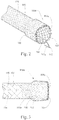
- Fig. 1 illustrates a partial sectional side view of exemplary modified stent 100 for use with a stent positioning device, such as that illustrated in Fig. 4 and further discussed below.
- Fig. 2 illustrates a perspective front view of proximal portion 100a of stent 100 illustrated in Fig. 1 .
- stent 100 is an elongated generally tubular body having proximal portion 100a, distal portion 100b, and lumen 100c extending between proximal portion 100a and distal portion 100b.
- the tubular body is generally constructed from one or more filaments or wires 106 that may be of various cross-sectional shapes and sizes.
- wires 106 may be flat in shape or may have a circular-shaped cross-section.
- Wires 106 may have any suitable diameter, such as, for example, from about 0.10 to about 0.30 mm.
- wires 106 may be formed from a variety of biocompatible materials.
- Wires 106 preferably comprise one or more elastically deformable materials such as shape memory alloys (e.g., stainless steel, nitinol, and the like), although other materials are contemplated.
- Wires 106 may also be made from or comprise any suitable biocompatible material(s).
- stents illustrated and equivalents thereto may include materials such as stainless steel, nitinol, MP35N, gold, tantalum, platinum or platinum iridium, niobium, tungsten, Iconel® (available from Special Metals Corporation, Huntington, West Virginia), ceramic, nickel, titanium, stainless steel/titanium composite, cobalt, chromium, cobalt/chromium alloys, magnesium, aluminum, or other biocompatible metals and or composites or alloys.
- materials such as stainless steel, nitinol, MP35N, gold, tantalum, platinum or platinum iridium, niobium, tungsten, Iconel® (available from Special Metals Corporation, Huntington, West Virginia), ceramic, nickel, titanium, stainless steel/titanium composite, cobalt, chromium, cobalt/chromium alloys, magnesium, aluminum, or other biocompatible metals and or composites or alloys.
- Examples of other materials that may be used to form stents include carbon or carbon fiber; cellulose acetate, cellulose nitrate, silicone, polyethylene terephthalate, polyurethane, polyamide, polyester, polyorthoester, polyanhydride, polyether sulfone, polycarbonate, polypropylene, ultra high molecular weight polyethylene, polytetrafluoroethylene, or another biocompatible polymeric material, or mixtures or copolymers of these; polylactic acid, polyglycolic acid or copolymers thereof; a polyanhydride, polycaprolactone, polyhydroxybutyrate valerate or another biodegradable polymer, or mixtures or copolymers of these; a protein, an extracellular matrix component, collagen, fibrin, or another biologic agent; or a suitable mixture of any of these.
- Stents illustrated and equivalents thereto may be fabricated to any suitable dimensions. Stents illustrated and equivalents thereto having a particular length and diameter may be selected based on the targeted vessel.
- a stent designed for esophageal implantation may have a length ranging from about 5 cm to about 15 cm and a body diameter of about 15 mm to about 25 mm.
- an esophageal stent may include one or more flanges or flares of about 10 mm to about 25 mm in length and about 20 mm to about 30 mm in diameter.
- a stent designed for colon implantation may have a length ranging from about 5 cm to about 15 cm and a body diameter of about 20 mm to about 25 mm.
- a colonic stent may include one or more flanges having a diameter of about 25 mm to about 35 mm.
- Stents illustrated and equivalents thereto may include a central body portion and one or more uniform flanges, or it may have two asymmetrically shaped flanges.
- a stent may include a uniform diameter along the length of stent but include slightly flared 108 proximal end 100a and/or distal end 100b of the stent.
- the central body portion may smoothly transition to a flange or flare, or alternatively, may progressively step up in diameter to a flange or flare.
- a stent may be implanted in a vessel (e.g., esophagus, duodenum, colon, trachea, or the like) such that the central body portion engages a diseased area and the proximal and distal ends engage healthy tissue adjacent the diseased area.
- a vessel e.g., esophagus, duodenum, colon, trachea, or the like
- stent 100 is depicted as having a substantially uniform diameter on the longitudinal axis and flares (or flanges) 108 having a slightly larger diameter than the middle portion, other stent configurations are possible.
- Stents illustrated and equivalents thereto may have any suitable helical pattern or angle such as those illustrated in Figs. 1-3 , as further discussed below.
- the radial force of the stent may be controlled by adjusting the angle accordingly. Stents with higher angles typically exert greater radial force and exhibit greater foreshortening during expansion from a compressed state. Stents with lower angles typically exert lower radial force and experience less foreshortening upon expansion. In some instances, the angle can be lowered because the membrane covering typically adds rigidity to the stent structure. In addition to adjusting the angle, the radial force of the stent can be adjusted through selection of particular filament materials, as well as the shape and size of the filaments or wires forming the stent structure.
- Stents illustrated and equivalents thereto may include one or more components configured to aid in visualization and/or adjustment of the stent during implantation, repositioning, or retrieval.
- a stent may include one or more radiopaque markers configured to provide for fluoroscopic visualization for accurate deployment and positioning. Radiopaque markers may be affixed ( e.g., by welding, gluing, suturing, or the like) at or near the ends of the stent at a cross point of wires 106.
- a stent may include four radiopaque markers with two markers affixed to a first flange and two to a second flange.
- radiopacity can be added to a stent through covering (also referred to as coating) processes such as sputtering, plating, or co-drawing gold or similar heavy metals onto the stent. Radiopacity can also be included by alloy addition. Radiopaque materials and markers may be comprised of any suitable biocompatible materials, such as tungsten, tantalum, molybdenum, platinum, gold, zirconium oxide, barium salt, bismuth salt, hafnium, and/or bismuth subcarbonate.
- Stents illustrated and equivalents thereto may be self-expanding, mechanically expandable, or a combination thereof.
- Self-expanding stents may be self-expanding under their inherent resilience or may be heat activated wherein the stent self-expands upon reaching a predetermined temperature or range of temperatures.
- One advantage of self-expanding stents is that traumas from external sources or natural changes in the shape of a body lumen do not permanently deform the stent.
- self-expanding stents may be preferred for use in vessels that are subject to changes in shape and/or changes in position, such as those of the peripheral and gastrointestinal systems.
- Peripheral vessels regularly change shape as the vessels experience trauma from external sources ( e.g , impacts to arms, legs, etc.); and many gastrointestinal vessels naturally change shape as peristaltic motion advances food through the digestive tract.
- covering 110 is illustrated as being a silicone elastomer, which is desired given its ability to stretch generally 500-700% without being compromised and such, is useful in stent applications
- other covering materials are contemplated, including but not limited to, polyethane (the fibers of which could be applied in layers at the same pitch of wires 106 to help close the gaps and provide a seal-like covering (but an air or water-tight seal need not be achieved)), TYVEK® (DuPont) (or other like materials) which are contemplated as being disposed between wires 106, as well as other materials such as polyurethane and non-woven materials.
- the covering could be made up of several layers with the filaments running in one direction with a pitch similar to one or more of wires 106 with the direction of the helical pattern alternated between layers. It is contemplated that such fabric layer may be bonded to one or more of wires 106.
- the covering membrane may cover over the entire stent framework from the proximal end to the distal end.
- the stent may have a covering over a central portion of the structure and one or more uncovered ends or flanges.
- a membrane covering may comprise any suitable biocompatible material.
- the membrane covering is an elastic or flexible material that can adapt to radial compression of a stent prior to delivery, as well as foreshortening of a stent during expansion from a compressed state.
- Suitable membrane materials include, for example, as discussed above, silicones ( e.g .
- the membrane covering is resistant to acid degradation.
- Stents illustrated and equivalents thereto may include a membrane covering applied by any suitable method as is known in the art.
- the membrane may be applied by spraying, dipping, painting, brushing, or padding.
- the membrane covering has a thickness ranging from about 0.0025 mm to about 2.5 mm. The thickness of the membrane may be selected, for example, by controlling the number of dips or passes made during the application process.
- a stent may include one or more bioactive agents coated on the stent surfaces.
- a bioactive agent may be applied directly on the surface of the stent (or on a primer layer which is placed directly on the surface of the stent).
- the bioactive agent may be mixed with a carrier material and this mixture applied to the stent.
- the release of the bioactive agent may be dependent on factors including composition, structure, and thickness of the carrier material.
- the carrier material may contain pre-existing channels, through which the bioactive agent may diffuse, or channels created by the release of bioactive agent, or another soluble substance, from the carrier material.
- One or more barrier layers may be deposited over the layer containing the bioactive agent.
- a combination of one or more layers of bioactive agent, mixtures of carrier material/bioactive, and barrier layers may be present.
- the bioactive agent may be mixed with a carrier material and coated onto the stent and then over coated with barrier layer(s).
- Multiple layers of bioactive agent, or mixtures of carrier material/bioactive, separated by barrier layers may be present to form a stent having multiple coverings. Different bioactive agents may be present in the different layers.
- a bioactive agent may be applied, for example, by spraying, dipping, pouring, pumping, brushing, wiping, vacuum deposition, vapor deposition, plasma deposition, electrostatic deposition, ultrasonic deposition, epitaxial growth, electrochemical deposition, or any other method known.
- a stent Prior to applying a membrane covering, and/or a bioactive agent, a stent may be polished, cleaned, and/or primed as is known in the art.
- a stent may be polished, for example, with an abrasive or by electropolishing.
- a stent may be cleaned by inserting the stent into various solvents, degreasers, and cleansers to remove any debris, residues, or unwanted materials from the stent surfaces.
- a primer coating may be applied to the stent prior to application of a membrane covering, bioactive, or other coating.
- the primer coating is dried to eliminate or remove any volatile components. Excess liquid may be blown off prior to drying the primer coating, which may be done at room temperature or at elevated temperatures under dry nitrogen or other suitable environments including an environment of reduced pressure.
- suture 102 having optional grasping loop 102a is positioned at distal portion 100b of stent 100.
- Suture 102 preferably comprises two thread-like elements circumferentially connected to distal portion 100b of stent 100 by being interwoven through the absolute end cells of stent 100, although other configurations are contemplated.
- Suture 103 having grasping loop 103a is positioned at proximal portion 100a of stent 100.
- Suture 103 preferably comprises two thread-like elements circumferentially connected to proximal portion 100a of stent 100 by being interwoven through the absolute end cells of stent 100, although other configurations are contemplated.
- An additional suture 104 is positioned longitudinally through the elongated tubular body of stent 100 and is connected to suture 103 and suture 102.
- Sutures 102, 103, and 104 are positioned and sized so that they do not interfere with the flow of material, such as food, bile, or blood, through stent 100.
- Sutures 102, 103, and 104 facilitate with the delivery, repositioning, and removal of stent 100 during or after implantation.
- Sutures 102, 103, and 104 are configured to compress and collapse the stent when opposite axial force are applied to them, and more particularly when opposite axial forces are applied to suture 103 and suture 104.
- the stent When one or more of the opposite axial forces are released, the stent will expand (or partially-expand (or deploy) if a force is still partially applied) thereby having a diameter larger than when in a collapsed (or partially-collapsed) diameter state.
- Sutures 102, 103, and 104 are one or more thread-like members that may comprise any appropriate biocompatible material, such as for example, suture materials or other polymeric or metallic materials such as polyethylene, ultra-high molecular weight polyethylene, polyester, nylon, stainless steel, nitinol, or the like.
- sutures 102, 103, and 104 may be covered with a material 112, such as suture grasping loops 102a and 103a illustrate, including but not limited to, polytetrafluoroethylene (PTFE), to prevent inadvertent cutting of the suture with a medical device, for example, forceps.
- PTFE polytetrafluoroethylene
- grasping loop 103a of suture 103 is positioned proximal to proximal portion 100a of stent 100, as illustrated in Figs. 1-2 .
- grasping loop 103a is pulled inside stent 100 as stent 100 collapses and foreshortens. Accordingly, the ability of stent 100 to fully collapse is not impaired by sutures 102, 103, and 104.
- Fig. 3 illustrates an alternate side view of stent 100 illustrated in Figs. 1-2 . If the diameter-to-length-to-foreshortening ratios of the stent are not ideal, suture 104 may need to be longer to accommodate the complete foreshortening of the stent. Thus, excess suture material may gather inside the inner lumen of the stent, as illustrated in Fig. 3 .
- the additional material can be addressed, such that it does not impede collapsing or expansion of the stent, by fashioning suture from an elastic material, including but not limited to a suture comprising an elastic portion and an in-elastic material portion, such that it is configured to recoil in a controlled matter, including but not limited to, forming the in-elastic portion into a braided portion.
- an elastic material including but not limited to a suture comprising an elastic portion and an in-elastic material portion, such that it is configured to recoil in a controlled matter, including but not limited to, forming the in-elastic portion into a braided portion.
- Other materials and configurations are contemplated, including those that will stretch to a known length and then become rigid once the known length is achieved.
- Such a configuration permits suture 104 to be positioned beside the inner wall of the stent so as not to impact the flow of food, bile, or blood, through the stent.
- Other suturing techniques are
- Stents illustrated and equivalents thereto may be delivered to a body lumen using various techniques, including by use of the devices illustrated in Figs. 4-8 and equivalents thereof.
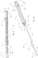
- Figs. 4 and 5 illustrate perspective views of exemplary stent positioning device 200.
- Fig. 6 illustrates a sectional side view of positioning device 200.
- positioning device 200 has two elements 204, 202 that engage respectively with suture 104 and suture grasping loop 103a of stent 100, such as that illustrated in Figs. 1-3 .
- Positioning device 200 includes proximal portion 200a and distal portion 200b.
- Hook 202 is disposed about the outer surface of shaft 210. Hook 202 engages with grasping loop 103a of exemplary stent 100.
- Actuation member 204 engages suture 104 of stent 100.
- Actuation member 204 is connected to advancement/retraction member 208.
- Actuation member 204 can assume a closed position (as illustrated in Fig. 4 ) and an open position (as illustrated in Fig. 5 ) (or a partially-open or partially-closed position) by rotating actuator 206 in the direction of Arrow A, thereby causing the grasping elements of actuation member 204 to separate in the direction of Arrow D (as illustrated in Fig. 6 ).
- Advancement/retraction member 208 is configured for axial movement through shaft 210 such that when advancement/retraction member 208 is advanced in a proximal direction or retracted in a distal direction of Arrow B, actuation member 204 moves proximally or distally, too, in the directions of Arrow C (as illustrated in Fig. 6 ).
- Figs. 7A-7B illustrate positioning device 200 illustrated in Fig. 4 in use.
- a stent such as that illustrated in Fig. 1
- actuation member 204 engages suture 104 to radially compress stent.
- hook 202 may be configured with a feature, such as a bump, angle, or other slip-prevention means, to prevent grasping loop 103a from unintentionally disengaging from hook 202.
- Advancement/retraction member 208 is pushed distally in the direction of arrow F such that advancement/retraction member 208 slides distally within shaft 210 causing actuation member 204 to move in a distal direction. Accordingly, stent 100 is stretched and caused to assume a collapsed position having a diameter less than its diameter when in a fully or partially-expanded state. More specifically, collapsing of stent 100 occurs because as advancement/retraction member 208 is slid distally along suture 104, suture 104 eventually becomes taut as additional forces are applied to it as hook 202 and actuation member 204 become further separated.
- the force is applied equally (and opposite) to distal portion 100b and proximal portion 100a of stent because suture 104 is connected to suture 102 and suture 103 which are thereby connected to distal portion 100b and proximal portion 100a of stent. Accordingly, when suture 104 is pulled taut by actuation member 208 when directed distally, stent 100 collapses radially. Stent 100 can then be introduced into the patient. Or, alternatively, if already within the patient, stent can be repositioned or removed.
- Fig. 7B illustrates a stent, such as that illustrated in Fig. 1 , being deployed.
- Stent 100 is connected to positioning device 200 such that hook 202 engages grasping loop 103a to prevent stent 100 from moving away from positioning device 200, and actuation member 204 engages suture 104.
- Advancement/retraction member 208 is pulled proximally in the direction of Arrow G such that advancement/retraction member 208 slides proximally within shaft 210 causing actuation member 204 to move in a proximal direction along suture 104 thereby releasing the force exerted thereto such that suture 204 is no longer taut thereby allowing stent 100 to assume an expanded position.
- stent 100 can be partially-collapsed or partially-expanded into any number of positions by only partially advancing or retracting advancement/retraction member 208 such that actuation member 204 varies how taut is suture 104.
- Positioning device 200 and equivalents thereof provide for initial stent engagement with positioning device 200 only on proximal portion 100a of stent 100 if desired. Engagement with stent can be accomplished under endoscope view having positioning device 200 alongside the endoscope or positioning device 200 being introduced through a working channel of an endoscope. Moreover because hook 202 and actuation member 204 are first positioned close to each other (having advancement/retraction member 208 pulled distally in the direction of Arrow G (as illustrated in Fig. 7B ), stent 100 can be engaged while positioning device 200 is positioned on the side proximal to stent 100. Accordingly, there is no need to initially pass positioning device 200 through lumen 100c of stent 100 to engage suture 104.
- Positioning device 200 is made from PEEK, nylon, and, or stainless steel, although other materials are contemplated.
- the column strength of actuation member 204 is configured such that it delivers enough force to collapse a stent. For example, when configured for use with an esophageal stent, the force is about 20-40 newtons, although other forces are contemplated depending upon the configuration of stent 100.
- Positioning device 200 is configured such that when advancement/retraction member 208 is pulled in its proximal-most position, hook 202 and actuation member 204 are configured such that stent is in an expanded position. For example, when configured for use with an esophageal stent, hook 202 and actuation member 204 are about 0-15 cm apart for a fully expanded state, although other distances are contemplated depending upon the configuration of stent 100. Alternatively, advancement/retraction member 208 may be retracted incrementally so as to assume any number of partially-expanded states.
- hook 202 and actuation member 204 are configured such that stent is in a collapsed position.
- hook 202 and actuation member 204 are about 20-40 cm apart for a fully collapsed state, although other distances are contemplated depending upon the configuration of stent 100.
- advancement/retraction member 208 may be advanced incrementally so as to assume any number of partially-collapsed states.
- positioning device 200 engaged with stent 100 may be advanced into the vicinity of the target anatomy.
- the targeted lumen may be predilated with a balloon catheter or other dilation device, if necessary or desired.
- stent 100 is delivered in a collapsed state, such that advancement/retraction member 208 is pushed in distally in the direction of Arrow F, illustrated in Fig. 7A , thereby compressing stent 100. This approach may reduce the risk of tissue perforations during delivery.
- stent 100 may be released from positioning device 200 by rotating actuator 206 to open and disengage actuation member 204 from suture 104 and unhooking hook 202 from grasping loop 103a. If stent 100 needs to be repositioned, positioning device 200 can be reengaged with stent 100, and stent 100 can be collapsed using positioning device 200. Accordingly, stent 100 may be repositioned and removed without damaging the surrounding tissue or bodily structures because it is able to reassume a collapsed or partially-collapsed position after full or partial-deployment. Moreover, after stent 100 has been dwelling within a patient, positioning device 200 can be used to reposition or remove stent 100 without damaging the surrounding tissue or bodily structures.
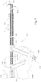
- Fig. 8 illustrates an alternate sectional side view of the proximal portion of exemplary stent positioning device 800 having proximal portion 800a and distal portion 800b.
- Positioning device 800 illustrated in Fig. 8 , is similar to positioning device 200 illustrated in Fig. 4 , however the advancement/retraction means, illustrated as advancement/retraction member 208 in Fig. 4 further includes handle 802, illustrated in Fig. 8 .
- Handle 208 is able to provide precise manipulation of the stent as the stent starts to collapse down using system 800. Thus, it provides a mechanical aid to help provide more and more force so that the stent may collapse in a more controlled manner than may otherwise be available by manually sliding a push-pull system.
- the positioning device 800 would be used similar to that of the system 200 illustrated in Fig. 4 , but after the stent begins to collapse, controlled collapsing of the stent would be further achieved by use of handle 802.
- actuator 206 is disengageable from engagement member 808. Accordingly, actuator 206 is first disengaged from engagement member 808 and pulled back proximally which effectively moves hook 202 and actuation member 204 close together on the proximal side of the stent. Once the stent sutures are engaged with hook 202 and actuation member 204, actuator 206 is pushed distally which effectively moves actuation member 204 through the stent.
- actuator 206 is right next to engagement member 808 and at that point, actuator 206 is coupled to engagement member 808. Once coupled together, handle 802 is used to start and complete the collapsing of the stent.
- first engagement member 808 is connected to advancement/retraction member 208.
- Second handle engagement member 810 is connected to shaft 210.
- Handle 802 is compressible and expandable through pivot joint 804 in the directions of Arrow E, and it is configured for single-hand use.
- a user places their hand around handle 802.
- first engagement member 808 and second engagement member 810 draw closer such that advancement/retraction member 208 is distally slid within shaft 210 causing actuation member 204 to move distally from hook 202 thereby causing an attached stent (not shown) to collapse.
- pivot joint 804 causes first engagement member 808 and second engagement member 810 to spread apart thereby causing advancement/retraction member 208 to slide proximally within shaft 210 causing actuation member 204 to move proximally toward hook 202 thereby permitting an attached stent (not shown) to expand.
- advancement/retraction member 208 may be partially advanced or retracted into any number of positions by partially compressing or uncompressing handle 802.
- positioning devices 200, 800 and equivalents thereto are contemplated, including but not limited to, those configured with multiple hooks, actuating members, other handle configurations, and/or combinations thereof so as to easily engage and disengage a stent for deployment into, repositioning, and removal from a patient.
- positioning device 200, 800 and equivalents thereto be a reusable device, such that it can be configured for use with multiple stents.
- positioning device 200, 800 and equivalents thereto may be disposable.
- positioning device 200, 800 and equivalents thereto may be retained for removal of the stent after the stent is no longer needed or desired to be dwelling within a patient.
- positioning device 200, 800 and equivalents thereto may be retained for repositioning of the stent in the event the stent needs to be moved after dwelling within a patient.
- the discovery of a stent and system for the delivery, repositioning, and removal of a stent benefits a patient through a system that uses the inherent properties of such a stent, including foreshortening.
- the stent can be radially constrained to reduce its diameter by applying a tensile force along its proximal and distal ends to collapse the stent permitting the efficient delivery, repositioning, and removal of the stent with less trauma to the patient.
Landscapes
- Health & Medical Sciences (AREA)
- Engineering & Computer Science (AREA)
- Biomedical Technology (AREA)
- Cardiology (AREA)
- Oral & Maxillofacial Surgery (AREA)
- Transplantation (AREA)
- Heart & Thoracic Surgery (AREA)
- Vascular Medicine (AREA)
- Life Sciences & Earth Sciences (AREA)
- Animal Behavior & Ethology (AREA)
- General Health & Medical Sciences (AREA)
- Public Health (AREA)
- Veterinary Medicine (AREA)
- Media Introduction/Drainage Providing Device (AREA)
- Prostheses (AREA)
Claims (15)
- Endoprothèse (100) comprenant :un corps tubulaire allongé comprenant une partie proximale (100a), une partie distale (100b) et une lumière (100c) s'étendant entre la partie proximale et la partie distale, le corps tubulaire allongé comprenant un ou plusieurs fils (106) ;une première suture (103) reliée circonférentiellement à la partie proximale du corps tubulaire allongé, la première suture étant configurée en une première boucle de préhension (103a) ;une deuxième suture (102) reliée circonférentiellement à la partie distale du corps tubulaire allongé ;caractérisée par :une troisième suture (104) disposée au moins partiellement dans la lumière du corps tubulaire allongé, la troisième suture étant reliée à la première suture et à la deuxième suture ;l'endoprothèse étant configurée pour s'affaisser et prendre un diamètre affaissé lorsque des forces axiales opposées sont appliquées à la première boucle de préhension et à la troisième suture.
- Endoprothèse selon la revendication 1, l'endoprothèse étant configurée pour se dilater et prendre un second diamètre, plus grand que le diamètre affaissé, lorsque les forces axiales opposées sont libérées d'au moins l'une des premières boucles de préhension ou de la troisième suture.
- Endoprothèse selon la revendication 1, comprenant en outre un revêtement, le revêtement comprenant de préférence du silicone.
- Endoprothèse selon la revendication 1, au moins l'une de la première suture, de la deuxième suture ou de la troisième suture comprenant du polytétrafluoroéthylène (PTFE).
- Endoprothèse selon la revendication 1, au moins l'une de la première suture, de la deuxième suture ou de la troisième suture étant élastique.
- Endoprothèse selon la revendication 1, la première boucle de préhension s'étendant de manière proximale à partir de l'endoprothèse.
- Endoprothèse selon la revendication 1, la première boucle de préhension étant disposée dans la lumière de l'endoprothèse.
- Endoprothèse selon la revendication 1, comprenant en outre une seconde boucle de préhension attachée à la seconde suture.
- Endoprothèse selon la revendication 8, la seconde boucle de préhension s'étendant de manière distale à partir de l'endoprothèse, un ou plusieurs fils étant enroulés et tissés en hélice.
- Endoprothèse selon l'une quelconque des revendications précédentes en combinaison avec un dispositif de positionnement destiné à être utilisé avec l'endoprothèse, le dispositif de positionnement comprenant :une partie proximale ;une partie distale ;un arbre ;un crochet disposé sur une surface extérieure de l'arbre ;un élément d'actionnement configurable dans une position ouverte et dans une position fermée ;un actionneur en communication avec l'élément d'actionnement, l'actionneur étant configuré pour ouvrir et fermer l'élément d'actionnement ;un élément d'avance/rétraction en communication avec l'actionneur et l'élément d'actionnement, l'élément d'avance/rétraction étant disposé de manière coulissante dans au moins une partie de l'arbre, l'élément d'avance/rétraction étant configuré pour déplacer axialement l'élément d'actionnement dans une direction de manière proximale vers le crochet et de manière distale à partir de celui-ci.
- Endoprothèse selon la revendication 10, l'actionneur étant configuré de manière rotative pour ouvrir et fermer l'élément d'actionnement.
- Endoprothèse selon la revendication 10, comprenant en outre une poignée configurée pour avancer et rétracter l'élément d'actionnement par rapport au crochet.
- Endoprothèse selon la revendication 12, la poignée comprenant un premier élément d'engagement et un second élément d'engagement, le premier élément d'engagement étant en communication avec l'élément d'avance/rétraction, et le second élément d'engagement étant en communication avec l'arbre ;
la poignée étant en outre configurée de telle sorte que lorsque le premier élément d'engagement et le second élément d'engagement sont comprimés, l'élément d'actionnement est déplacé de manière distale du crochet pour prendre une première position. - Endoprothèse selon la revendication 13, la poignée étant en outre configurée pour positionner l'élément d'actionnement dans une seconde position lorsque le premier élément d'engagement et le second élément d'engagement ne sont pas comprimés, de sorte que le crochet est plus proche de l'élément d'actionnement que dans la première position.
- Endoprothèse selon la revendication 10, l'endoprothèse étant configurée pour se dilater et prendre un second diamètre, plus grand que le diamètre affaissé, lorsque l'élément d'avance/rétraction est dirigé axialement de sorte que l'élément d'actionnement est déplacé vers le crochet.
Applications Claiming Priority (2)
| Application Number | Priority Date | Filing Date | Title |
|---|---|---|---|
| US201161545755P | 2011-10-11 | 2011-10-11 | |
| PCT/US2012/059444 WO2013055729A1 (fr) | 2011-10-11 | 2012-10-10 | Système de pose, de repositionnement et de retrait d'endoprothèses |
Publications (2)
| Publication Number | Publication Date |
|---|---|
| EP2765959A1 EP2765959A1 (fr) | 2014-08-20 |
| EP2765959B1 true EP2765959B1 (fr) | 2019-10-09 |
Family
ID=47071476
Family Applications (1)
| Application Number | Title | Priority Date | Filing Date |
|---|---|---|---|
| EP12775908.2A Not-in-force EP2765959B1 (fr) | 2011-10-11 | 2012-10-10 | Système de pose, de repositionnement et de retrait d'endoprothèses |
Country Status (5)
| Country | Link |
|---|---|
| US (1) | US9549833B2 (fr) |
| EP (1) | EP2765959B1 (fr) |
| JP (1) | JP5845357B2 (fr) |
| AU (1) | AU2012323300B2 (fr) |
| WO (1) | WO2013055729A1 (fr) |
Families Citing this family (26)
| Publication number | Priority date | Publication date | Assignee | Title |
|---|---|---|---|---|
| NZ554495A (en) | 2004-10-15 | 2010-09-30 | Bfkw Llc | Bariatric device and method with lumen exerting force on eosophagus or stomach areas |
| US8529431B2 (en) | 2007-02-14 | 2013-09-10 | Bfkw, Llc | Bariatric device and method |
| KR101498584B1 (ko) * | 2013-05-15 | 2015-03-04 | 주식회사 스텐다드싸이텍 | 이동방지용 스텐트 |
| US9833347B2 (en) | 2014-03-25 | 2017-12-05 | Boston Scientific Scimed, Inc. | Apparatuses for manipulating medical devices and related methods for use |
| US20160089255A1 (en) * | 2014-09-26 | 2016-03-31 | Anaxiom Corporation | Removable vascular occlusion device |
| CA2972582A1 (fr) | 2014-12-29 | 2016-07-07 | Bfkw, Llc | Fixation de dispositif intraluminal |
| CN107405206A (zh) | 2015-01-14 | 2017-11-28 | 库克医学技术有限责任公司 | 缝合线‑金属丝支架部署系统 |
| JP6348852B2 (ja) * | 2015-01-21 | 2018-06-27 | オリンパス株式会社 | 処置具 |
| WO2016126967A1 (fr) | 2015-02-06 | 2016-08-11 | Boston Scientific Scimed, Inc. | Endoprothèse vasculaire anti-migration |
| US9889027B2 (en) | 2015-08-26 | 2018-02-13 | Cook Medical Technologies Llc | Stent delivery system |
| FR3041527B1 (fr) * | 2015-09-28 | 2020-12-04 | Balt Extrusion | Dispositif permettant d'exercer une traction sur un stent implante dans un vaisseau sanguin |
| DE202016105963U1 (de) | 2016-10-24 | 2018-01-25 | Nvt Ag | Intraluminale Gefäßprothese zur Implantation in das Herz oder Herzgefäße eines Patienten |
| US10765545B2 (en) | 2016-10-31 | 2020-09-08 | Cook Medical Technologies Llc | Suture esophageal stent introducer |
| US11413175B2 (en) | 2016-10-31 | 2022-08-16 | Cook Medical Technologies Llc | Tube and suture stent introducer system |
| US10702408B2 (en) | 2016-10-31 | 2020-07-07 | Cook Medical Technologies Llc | Suture esophageal stent introducer |
| US10500080B2 (en) * | 2016-10-31 | 2019-12-10 | Cook Medical Technologies Llc | Suture esophageal stent introducer |
| US11246727B2 (en) | 2016-10-31 | 2022-02-15 | Cook Medical Technologies Llc | Suture esophageal stent introducer |
| US11141299B2 (en) | 2016-10-31 | 2021-10-12 | Cook Medical Technologies Llc | Suture esophageal stent introducer |
| US10849775B2 (en) | 2016-10-31 | 2020-12-01 | Cook Medical Technologies Llc | Suture esophageal stent introducer parallel handle |
| US11141298B2 (en) | 2016-10-31 | 2021-10-12 | Cook Medical Technologies Llc | Suture esophageal stent introducer |
| US10433993B2 (en) | 2017-01-20 | 2019-10-08 | Medtronic Vascular, Inc. | Valve prosthesis having a radially-expandable sleeve integrated thereon for delivery and prevention of paravalvular leakage |
| US10709541B2 (en) * | 2017-04-28 | 2020-07-14 | Cook Medical Technologies Llc | Systems and methods for adjusting the diameter of an endoluminal prosthesis and an endoluminal prosthesis configured for the same |
| US20210137711A1 (en) * | 2018-03-30 | 2021-05-13 | Kurume University | Stent |
| WO2021051075A1 (fr) * | 2019-09-12 | 2021-03-18 | First Pass, Llc | Appareil de récupération d'articulation intravasculaire |
| US20220287831A1 (en) | 2021-03-12 | 2022-09-15 | Troy Thornton | Device and method for variable blood flow occlusion |
| US20230233312A1 (en) * | 2022-01-21 | 2023-07-27 | Covidien Lp | Stent design for transluminal application |
Citations (4)
| Publication number | Priority date | Publication date | Assignee | Title |
|---|---|---|---|---|
| US5242452A (en) * | 1991-10-11 | 1993-09-07 | Kanji Inoue | Device for collapsing an appliance collapsible for insertion into human organs |
| EP1870057A1 (fr) * | 2006-06-21 | 2007-12-26 | Morel d'Arleux, Eric | Endoprothèse du type "stent" |
| US20080140181A1 (en) * | 2004-10-25 | 2008-06-12 | Reynolds Jason M | Stent Removal and Repositioning Aid and Associated Method |
| US20110160836A1 (en) * | 2008-06-20 | 2011-06-30 | Vysera Biomedical Limited | Valve device |
Family Cites Families (7)
| Publication number | Priority date | Publication date | Assignee | Title |
|---|---|---|---|---|
| US7018401B1 (en) * | 1999-02-01 | 2006-03-28 | Board Of Regents, The University Of Texas System | Woven intravascular devices and methods for making the same and apparatus for delivery of the same |
| DE10118944B4 (de) * | 2001-04-18 | 2013-01-31 | Merit Medical Systems, Inc. | Entfernbare, im wesentlichen zylindrische Implantate |
| WO2006047520A2 (fr) | 2004-10-25 | 2006-05-04 | Alveolus, Inc. | Dispositif de repositionnement et de retrait d'une endoprothese vasculaire et methode associee |
| WO2008066923A1 (fr) | 2006-11-30 | 2008-06-05 | William Cook Europe Aps | Mécanisme de libération d'implant |
| US9314356B2 (en) | 2010-01-29 | 2016-04-19 | Cook Medical Technologies Llc | Mechanically expandable delivery and dilation systems |
| EP2240126B1 (fr) | 2008-02-13 | 2014-01-08 | Cook Medical Technologies LLC | Appareil et procédé d'ajustement d'une greffe d'endoprothèse vasculaire ou d'un dispositif similaire |
| CA2771120C (fr) * | 2009-09-10 | 2017-07-11 | Boston Scientific Scimed, Inc. | Endoprothese avec repositionnement de filament ou element de recuperation et structure protectrice |
-
2012
- 2012-10-10 WO PCT/US2012/059444 patent/WO2013055729A1/fr active Application Filing
- 2012-10-10 EP EP12775908.2A patent/EP2765959B1/fr not_active Not-in-force
- 2012-10-10 AU AU2012323300A patent/AU2012323300B2/en not_active Ceased
- 2012-10-10 US US13/648,591 patent/US9549833B2/en active Active
- 2012-10-10 JP JP2014535803A patent/JP5845357B2/ja not_active Expired - Fee Related
Patent Citations (4)
| Publication number | Priority date | Publication date | Assignee | Title |
|---|---|---|---|---|
| US5242452A (en) * | 1991-10-11 | 1993-09-07 | Kanji Inoue | Device for collapsing an appliance collapsible for insertion into human organs |
| US20080140181A1 (en) * | 2004-10-25 | 2008-06-12 | Reynolds Jason M | Stent Removal and Repositioning Aid and Associated Method |
| EP1870057A1 (fr) * | 2006-06-21 | 2007-12-26 | Morel d'Arleux, Eric | Endoprothèse du type "stent" |
| US20110160836A1 (en) * | 2008-06-20 | 2011-06-30 | Vysera Biomedical Limited | Valve device |
Also Published As
| Publication number | Publication date |
|---|---|
| WO2013055729A1 (fr) | 2013-04-18 |
| JP2014534844A (ja) | 2014-12-25 |
| JP5845357B2 (ja) | 2016-01-20 |
| AU2012323300B2 (en) | 2015-05-28 |
| EP2765959A1 (fr) | 2014-08-20 |
| US9549833B2 (en) | 2017-01-24 |
| AU2012323300A1 (en) | 2014-04-17 |
| US20130090714A1 (en) | 2013-04-11 |
Similar Documents
| Publication | Publication Date | Title |
|---|---|---|
| EP2765959B1 (fr) | Système de pose, de repositionnement et de retrait d'endoprothèses | |
| US20230128901A1 (en) | Surgical implant devices and methods for their manufacture and use | |
| US10524908B2 (en) | Controlled tip release stent graft delivery system and method | |
| US10034740B2 (en) | Covered stent | |
| EP2018138B1 (fr) | Appareil et procédé permettant de charger et de mise en place d'une endoprothèse | |
| EP1923020B1 (fr) | Endoprothèse avec pointes d'ancrage | |
| US9095463B2 (en) | Stent-graft delivery having a tip capture mechanism with elongated cables for gradual deployment and repositioning | |
| AU2014280045B2 (en) | Stent delivery system | |
| EP1982677A2 (fr) | Système de mise en place pour greffe d'endoprothèse vasculaire | |
| US20080082158A1 (en) | Method for Deployment of a Stent Graft | |
| US20100268315A1 (en) | Castellated Sleeve Stent-Graft Delivery System and Method | |
| EP2836173A1 (fr) | Système de mise en place d'une endoprothèse équipé d'un mécanisme de capture terminal à tige rotative unique | |
| JP2003521996A (ja) | 管内人工補装具の送達のための装置および方法 | |
| US20230081356A1 (en) | Delivery system with device deployment features, and associated methods | |
| AU2011352142A1 (en) | Improved surgical implant devices and methods for their manufacture and use |
Legal Events
| Date | Code | Title | Description |
|---|---|---|---|
| PUAI | Public reference made under article 153(3) epc to a published international application that has entered the european phase |
Free format text: ORIGINAL CODE: 0009012 |
|
| 17P | Request for examination filed |
Effective date: 20140328 |
|
| AK | Designated contracting states |
Kind code of ref document: A1 Designated state(s): AL AT BE BG CH CY CZ DE DK EE ES FI FR GB GR HR HU IE IS IT LI LT LU LV MC MK MT NL NO PL PT RO RS SE SI SK SM TR |
|
| DAX | Request for extension of the european patent (deleted) | ||
| STAA | Information on the status of an ep patent application or granted ep patent |
Free format text: STATUS: EXAMINATION IS IN PROGRESS |
|
| 17Q | First examination report despatched |
Effective date: 20170428 |
|
| GRAP | Despatch of communication of intention to grant a patent |
Free format text: ORIGINAL CODE: EPIDOSNIGR1 |
|
| STAA | Information on the status of an ep patent application or granted ep patent |
Free format text: STATUS: GRANT OF PATENT IS INTENDED |
|
| INTG | Intention to grant announced |
Effective date: 20190502 |
|
| GRAS | Grant fee paid |
Free format text: ORIGINAL CODE: EPIDOSNIGR3 |
|
| GRAA | (expected) grant |
Free format text: ORIGINAL CODE: 0009210 |
|
| STAA | Information on the status of an ep patent application or granted ep patent |
Free format text: STATUS: THE PATENT HAS BEEN GRANTED |
|
| AK | Designated contracting states |
Kind code of ref document: B1 Designated state(s): AL AT BE BG CH CY CZ DE DK EE ES FI FR GB GR HR HU IE IS IT LI LT LU LV MC MK MT NL NO PL PT RO RS SE SI SK SM TR |
|
| REG | Reference to a national code |
Ref country code: GB Ref legal event code: FG4D |
|
| REG | Reference to a national code |
Ref country code: CH Ref legal event code: EP |
|
| REG | Reference to a national code |
Ref country code: IE Ref legal event code: FG4D |
|
| REG | Reference to a national code |
Ref country code: DE Ref legal event code: R096 Ref document number: 602012064739 Country of ref document: DE |
|
| REG | Reference to a national code |
Ref country code: AT Ref legal event code: REF Ref document number: 1187930 Country of ref document: AT Kind code of ref document: T Effective date: 20191115 |
|
| REG | Reference to a national code |
Ref country code: NL Ref legal event code: MP Effective date: 20191009 |
|
| REG | Reference to a national code |
Ref country code: LT Ref legal event code: MG4D |
|
| REG | Reference to a national code |
Ref country code: AT Ref legal event code: MK05 Ref document number: 1187930 Country of ref document: AT Kind code of ref document: T Effective date: 20191009 |
|
| PG25 | Lapsed in a contracting state [announced via postgrant information from national office to epo] |
Ref country code: PT Free format text: LAPSE BECAUSE OF FAILURE TO SUBMIT A TRANSLATION OF THE DESCRIPTION OR TO PAY THE FEE WITHIN THE PRESCRIBED TIME-LIMIT Effective date: 20200210 Ref country code: ES Free format text: LAPSE BECAUSE OF FAILURE TO SUBMIT A TRANSLATION OF THE DESCRIPTION OR TO PAY THE FEE WITHIN THE PRESCRIBED TIME-LIMIT Effective date: 20191009 Ref country code: AT Free format text: LAPSE BECAUSE OF FAILURE TO SUBMIT A TRANSLATION OF THE DESCRIPTION OR TO PAY THE FEE WITHIN THE PRESCRIBED TIME-LIMIT Effective date: 20191009 Ref country code: GR Free format text: LAPSE BECAUSE OF FAILURE TO SUBMIT A TRANSLATION OF THE DESCRIPTION OR TO PAY THE FEE WITHIN THE PRESCRIBED TIME-LIMIT Effective date: 20200110 Ref country code: LV Free format text: LAPSE BECAUSE OF FAILURE TO SUBMIT A TRANSLATION OF THE DESCRIPTION OR TO PAY THE FEE WITHIN THE PRESCRIBED TIME-LIMIT Effective date: 20191009 Ref country code: SE Free format text: LAPSE BECAUSE OF FAILURE TO SUBMIT A TRANSLATION OF THE DESCRIPTION OR TO PAY THE FEE WITHIN THE PRESCRIBED TIME-LIMIT Effective date: 20191009 Ref country code: BG Free format text: LAPSE BECAUSE OF FAILURE TO SUBMIT A TRANSLATION OF THE DESCRIPTION OR TO PAY THE FEE WITHIN THE PRESCRIBED TIME-LIMIT Effective date: 20200109 Ref country code: FI Free format text: LAPSE BECAUSE OF FAILURE TO SUBMIT A TRANSLATION OF THE DESCRIPTION OR TO PAY THE FEE WITHIN THE PRESCRIBED TIME-LIMIT Effective date: 20191009 Ref country code: NO Free format text: LAPSE BECAUSE OF FAILURE TO SUBMIT A TRANSLATION OF THE DESCRIPTION OR TO PAY THE FEE WITHIN THE PRESCRIBED TIME-LIMIT Effective date: 20200109 Ref country code: PL Free format text: LAPSE BECAUSE OF FAILURE TO SUBMIT A TRANSLATION OF THE DESCRIPTION OR TO PAY THE FEE WITHIN THE PRESCRIBED TIME-LIMIT Effective date: 20191009 Ref country code: LT Free format text: LAPSE BECAUSE OF FAILURE TO SUBMIT A TRANSLATION OF THE DESCRIPTION OR TO PAY THE FEE WITHIN THE PRESCRIBED TIME-LIMIT Effective date: 20191009 Ref country code: NL Free format text: LAPSE BECAUSE OF FAILURE TO SUBMIT A TRANSLATION OF THE DESCRIPTION OR TO PAY THE FEE WITHIN THE PRESCRIBED TIME-LIMIT Effective date: 20191009 |
|
| PG25 | Lapsed in a contracting state [announced via postgrant information from national office to epo] |
Ref country code: HR Free format text: LAPSE BECAUSE OF FAILURE TO SUBMIT A TRANSLATION OF THE DESCRIPTION OR TO PAY THE FEE WITHIN THE PRESCRIBED TIME-LIMIT Effective date: 20191009 Ref country code: IS Free format text: LAPSE BECAUSE OF FAILURE TO SUBMIT A TRANSLATION OF THE DESCRIPTION OR TO PAY THE FEE WITHIN THE PRESCRIBED TIME-LIMIT Effective date: 20200224 Ref country code: RS Free format text: LAPSE BECAUSE OF FAILURE TO SUBMIT A TRANSLATION OF THE DESCRIPTION OR TO PAY THE FEE WITHIN THE PRESCRIBED TIME-LIMIT Effective date: 20191009 |
|
| REG | Reference to a national code |
Ref country code: CH Ref legal event code: PL |
|
| PG25 | Lapsed in a contracting state [announced via postgrant information from national office to epo] |
Ref country code: AL Free format text: LAPSE BECAUSE OF FAILURE TO SUBMIT A TRANSLATION OF THE DESCRIPTION OR TO PAY THE FEE WITHIN THE PRESCRIBED TIME-LIMIT Effective date: 20191009 |
|
| REG | Reference to a national code |
Ref country code: DE Ref legal event code: R097 Ref document number: 602012064739 Country of ref document: DE |
|
| PG2D | Information on lapse in contracting state deleted |
Ref country code: IS |
|
| PG25 | Lapsed in a contracting state [announced via postgrant information from national office to epo] |
Ref country code: LU Free format text: LAPSE BECAUSE OF NON-PAYMENT OF DUE FEES Effective date: 20191010 Ref country code: RO Free format text: LAPSE BECAUSE OF FAILURE TO SUBMIT A TRANSLATION OF THE DESCRIPTION OR TO PAY THE FEE WITHIN THE PRESCRIBED TIME-LIMIT Effective date: 20191009 Ref country code: EE Free format text: LAPSE BECAUSE OF FAILURE TO SUBMIT A TRANSLATION OF THE DESCRIPTION OR TO PAY THE FEE WITHIN THE PRESCRIBED TIME-LIMIT Effective date: 20191009 Ref country code: CZ Free format text: LAPSE BECAUSE OF FAILURE TO SUBMIT A TRANSLATION OF THE DESCRIPTION OR TO PAY THE FEE WITHIN THE PRESCRIBED TIME-LIMIT Effective date: 20191009 Ref country code: LI Free format text: LAPSE BECAUSE OF NON-PAYMENT OF DUE FEES Effective date: 20191031 Ref country code: CH Free format text: LAPSE BECAUSE OF NON-PAYMENT OF DUE FEES Effective date: 20191031 Ref country code: DK Free format text: LAPSE BECAUSE OF FAILURE TO SUBMIT A TRANSLATION OF THE DESCRIPTION OR TO PAY THE FEE WITHIN THE PRESCRIBED TIME-LIMIT Effective date: 20191009 Ref country code: MC Free format text: LAPSE BECAUSE OF FAILURE TO SUBMIT A TRANSLATION OF THE DESCRIPTION OR TO PAY THE FEE WITHIN THE PRESCRIBED TIME-LIMIT Effective date: 20191009 Ref country code: IS Free format text: LAPSE BECAUSE OF FAILURE TO SUBMIT A TRANSLATION OF THE DESCRIPTION OR TO PAY THE FEE WITHIN THE PRESCRIBED TIME-LIMIT Effective date: 20200209 |
|
| REG | Reference to a national code |
Ref country code: BE Ref legal event code: MM Effective date: 20191031 |
|
| PLBE | No opposition filed within time limit |
Free format text: ORIGINAL CODE: 0009261 |
|
| STAA | Information on the status of an ep patent application or granted ep patent |
Free format text: STATUS: NO OPPOSITION FILED WITHIN TIME LIMIT |
|
| PG25 | Lapsed in a contracting state [announced via postgrant information from national office to epo] |
Ref country code: SM Free format text: LAPSE BECAUSE OF FAILURE TO SUBMIT A TRANSLATION OF THE DESCRIPTION OR TO PAY THE FEE WITHIN THE PRESCRIBED TIME-LIMIT Effective date: 20191009 Ref country code: IT Free format text: LAPSE BECAUSE OF FAILURE TO SUBMIT A TRANSLATION OF THE DESCRIPTION OR TO PAY THE FEE WITHIN THE PRESCRIBED TIME-LIMIT Effective date: 20191009 Ref country code: BE Free format text: LAPSE BECAUSE OF NON-PAYMENT OF DUE FEES Effective date: 20191031 Ref country code: SK Free format text: LAPSE BECAUSE OF FAILURE TO SUBMIT A TRANSLATION OF THE DESCRIPTION OR TO PAY THE FEE WITHIN THE PRESCRIBED TIME-LIMIT Effective date: 20191009 |
|
| 26N | No opposition filed |
Effective date: 20200710 |
|
| PG25 | Lapsed in a contracting state [announced via postgrant information from national office to epo] |
Ref country code: FR Free format text: LAPSE BECAUSE OF NON-PAYMENT OF DUE FEES Effective date: 20191209 |
|
| PG25 | Lapsed in a contracting state [announced via postgrant information from national office to epo] |
Ref country code: SI Free format text: LAPSE BECAUSE OF FAILURE TO SUBMIT A TRANSLATION OF THE DESCRIPTION OR TO PAY THE FEE WITHIN THE PRESCRIBED TIME-LIMIT Effective date: 20191009 |
|
| PG25 | Lapsed in a contracting state [announced via postgrant information from national office to epo] |
Ref country code: CY Free format text: LAPSE BECAUSE OF FAILURE TO SUBMIT A TRANSLATION OF THE DESCRIPTION OR TO PAY THE FEE WITHIN THE PRESCRIBED TIME-LIMIT Effective date: 20191009 |
|
| PG25 | Lapsed in a contracting state [announced via postgrant information from national office to epo] |
Ref country code: MT Free format text: LAPSE BECAUSE OF FAILURE TO SUBMIT A TRANSLATION OF THE DESCRIPTION OR TO PAY THE FEE WITHIN THE PRESCRIBED TIME-LIMIT Effective date: 20191009 Ref country code: HU Free format text: LAPSE BECAUSE OF FAILURE TO SUBMIT A TRANSLATION OF THE DESCRIPTION OR TO PAY THE FEE WITHIN THE PRESCRIBED TIME-LIMIT; INVALID AB INITIO Effective date: 20121010 |
|
| PGFP | Annual fee paid to national office [announced via postgrant information from national office to epo] |
Ref country code: IE Payment date: 20210927 Year of fee payment: 10 |
|
| PGFP | Annual fee paid to national office [announced via postgrant information from national office to epo] |
Ref country code: GB Payment date: 20210929 Year of fee payment: 10 |
|
| PGFP | Annual fee paid to national office [announced via postgrant information from national office to epo] |
Ref country code: DE Payment date: 20210916 Year of fee payment: 10 |
|
| PG25 | Lapsed in a contracting state [announced via postgrant information from national office to epo] |
Ref country code: TR Free format text: LAPSE BECAUSE OF FAILURE TO SUBMIT A TRANSLATION OF THE DESCRIPTION OR TO PAY THE FEE WITHIN THE PRESCRIBED TIME-LIMIT Effective date: 20191009 |
|
| PG25 | Lapsed in a contracting state [announced via postgrant information from national office to epo] |
Ref country code: MK Free format text: LAPSE BECAUSE OF FAILURE TO SUBMIT A TRANSLATION OF THE DESCRIPTION OR TO PAY THE FEE WITHIN THE PRESCRIBED TIME-LIMIT Effective date: 20191009 |
|
| REG | Reference to a national code |
Ref country code: DE Ref legal event code: R119 Ref document number: 602012064739 Country of ref document: DE |
|
| GBPC | Gb: european patent ceased through non-payment of renewal fee |
Effective date: 20221010 |
|
| PG25 | Lapsed in a contracting state [announced via postgrant information from national office to epo] |
Ref country code: DE Free format text: LAPSE BECAUSE OF NON-PAYMENT OF DUE FEES Effective date: 20230503 |
|
| PG25 | Lapsed in a contracting state [announced via postgrant information from national office to epo] |
Ref country code: IE Free format text: LAPSE BECAUSE OF NON-PAYMENT OF DUE FEES Effective date: 20221010 Ref country code: GB Free format text: LAPSE BECAUSE OF NON-PAYMENT OF DUE FEES Effective date: 20221010 |