EP2765764A1 - Dither matrix generating method, image processing method, image processing device, program, and non-transitory storage medium storing program - Google Patents
Dither matrix generating method, image processing method, image processing device, program, and non-transitory storage medium storing program Download PDFInfo
- Publication number
- EP2765764A1 EP2765764A1 EP13197191.3A EP13197191A EP2765764A1 EP 2765764 A1 EP2765764 A1 EP 2765764A1 EP 13197191 A EP13197191 A EP 13197191A EP 2765764 A1 EP2765764 A1 EP 2765764A1
- Authority
- EP
- European Patent Office
- Prior art keywords
- dither matrix
- dots
- threshold values
- halftone
- positions
- Prior art date
- Legal status (The legal status is an assumption and is not a legal conclusion. Google has not performed a legal analysis and makes no representation as to the accuracy of the status listed.)
- Granted
Links
Images



Classifications
-
- H—ELECTRICITY
- H04—ELECTRIC COMMUNICATION TECHNIQUE
- H04N—PICTORIAL COMMUNICATION, e.g. TELEVISION
- H04N1/00—Scanning, transmission or reproduction of documents or the like, e.g. facsimile transmission; Details thereof
- H04N1/40—Picture signal circuits
- H04N1/405—Halftoning, i.e. converting the picture signal of a continuous-tone original into a corresponding signal showing only two levels
- H04N1/4055—Halftoning, i.e. converting the picture signal of a continuous-tone original into a corresponding signal showing only two levels producing a clustered dots or a size modulated halftone pattern
-
- G—PHYSICS
- G06—COMPUTING OR CALCULATING; COUNTING
- G06K—GRAPHICAL DATA READING; PRESENTATION OF DATA; RECORD CARRIERS; HANDLING RECORD CARRIERS
- G06K15/00—Arrangements for producing a permanent visual presentation of the output data, e.g. computer output printers
- G06K15/02—Arrangements for producing a permanent visual presentation of the output data, e.g. computer output printers using printers
- G06K15/18—Conditioning data for presenting it to the physical printing elements
- G06K15/1867—Post-processing of the composed and rasterized print image
- G06K15/1872—Image enhancement
- G06K15/1881—Halftoning
-
- G—PHYSICS
- G06—COMPUTING OR CALCULATING; COUNTING
- G06K—GRAPHICAL DATA READING; PRESENTATION OF DATA; RECORD CARRIERS; HANDLING RECORD CARRIERS
- G06K15/00—Arrangements for producing a permanent visual presentation of the output data, e.g. computer output printers
- G06K15/02—Arrangements for producing a permanent visual presentation of the output data, e.g. computer output printers using printers
- G06K15/18—Conditioning data for presenting it to the physical printing elements
- G06K15/1867—Post-processing of the composed and rasterized print image
- G06K15/1872—Image enhancement
- G06K15/1876—Decreasing spatial resolution; Dithering
-
- H—ELECTRICITY
- H04—ELECTRIC COMMUNICATION TECHNIQUE
- H04N—PICTORIAL COMMUNICATION, e.g. TELEVISION
- H04N1/00—Scanning, transmission or reproduction of documents or the like, e.g. facsimile transmission; Details thereof
- H04N1/40—Picture signal circuits
- H04N1/405—Halftoning, i.e. converting the picture signal of a continuous-tone original into a corresponding signal showing only two levels
-
- H—ELECTRICITY
- H04—ELECTRIC COMMUNICATION TECHNIQUE
- H04N—PICTORIAL COMMUNICATION, e.g. TELEVISION
- H04N1/00—Scanning, transmission or reproduction of documents or the like, e.g. facsimile transmission; Details thereof
- H04N1/40—Picture signal circuits
- H04N1/409—Edge or detail enhancement; Noise or error suppression
- H04N1/4092—Edge or detail enhancement
Definitions
- the present invention relates to a dither matrix generating method, an image processing method, an image processing device, a program, and a non-transitory storage medium storing a program.
- gradation is expressed by halftone processing.
- a dithering method can be considered.
- a halftone is reproduced by a combination of density gradation (intensity modulation) and area gradation (area modulation), for which a number of levels is fewer than that of the original (cf. Patent Document 1 (Japanese Unexamined Patent Publication No. 2003-152999 ), for example).
- a concentration type dither matrix is often used in halftone processing, for which a dither method according to related art is applied.
- the concentration type dither matrix is often used because it demonstrates good dot reproducibility and high image quality.
- a gap tends to be generated between neighboring dots, and a fine line tends to be broken.
- breaking of a fine line has been reduced.
- the distributed dithering may cause a color shift, for example, and may lower image quality.
- a size of a matrix may be increased. Accordingly, printing speed may be reduced, and cost may be increased due to an increase of required memory capacity.
- An embodiment of the present invention has been developed in view of the above-described problems. It is desirable to provide a dither matrix generating method, which can reduce breaking of a fine line and which can enhance image quality. It is also desirable to provide an image processing method; an image processing device; and a program, in which the above-described dither matrix is utilized.
- a dither matrix generating method In the method, halftone dots are formed by growing corresponding dots.
- the method includes a first generating step of generating first threshold values of a dither matrix, so that the dots grow until a predetermined halftone dot area ratio is achieved, wherein, when the predetermined halftone dot area ratio is achieved, the halftone dots contact each other; and a second generating step of generating second threshold values of the dither matrix, so that the dots grow beyond the predetermined halftone dot area ratio.
- breaking of the fine line can be reduced, and, at the same time, the image quality can be enhanced.
- a reference value of a halftone dot area ratio is set to be the halftone dot area ratio at a moment at which halftone dots of a concentration type dither matrix contact each other.
- a process prior to achieving the reference value is defined to be a first threshold value generating step, and breaking of a fine line is reduced. Once the halftone dots contact each other, a fine line is not to be broken after that.
- the process subsequent to achieving the reference value is defined to be a second threshold value generating step. In the second threshold value generating step, dot reproducibility is improved and image quality is enhanced by using a concentration type dither matrix.
- FIGS. 1A - 1E show examples of half-toning to which concentration type dithering is applied.
- the density is low. The density increases in an order of 1B, 1C, 1D, and 1E.
- the concentration type dithering since dots are formed while concentrating the dots, dot reproducibility is good and image quality is high. However, in a low density portion, since a gap tends to be formed between dots, a fine line tends to be broken. As the area ratio of the halftone dots is increased while applying the concentration type dithering, the concentrated dots grow, and thereby a single large halftone dot is formed.
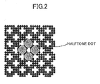
- FIG. 2 shows an example of a halftone dot area ratio of halftone dots, with which a fine line tends not to be broken.
- halftone dots which become large, contact each other.
- a gap may not be generated between the halftone dots. Accordingly, a fine line may not be broken.
- FIG. 3 shows an example of half-toning, for which dithering according to the embodiment is applied.
- the dithering according to the embodiment reduces breaking of a fine line.
- FIG. 3 shows that, in the halftone processing prior to achieving the halftone area dot ratio with which a fine line tends not to be broken (cf. FIG. 2 ), dots are dispersed as much as possible. By doing this, some dots are generated at corresponding positions, at which a fine line would be broken, if the concentration type dithering were applied. In this manner, a fine line tends not to be broken in the halftone processing prior to achieving the halftone area dot ratio with which a fine line tends not to be broken. For the halftone processing subsequent to achieving the halftone area dot ratio with which a fine line tends not to be broken, dots are stabilized and image quality is enhanced by using concentration type dithering.
- FIG. 4 shows a configuration of an image processing device according to the embodiment.
- the reference numeral 1 denotes input gradation data
- the reference numeral 2 denotes a comparator
- the reference numeral 3 denotes a dither matrix generating unit
- the reference numeral 4 denotes a dither matrix storage unit
- the reference numeral 5 denotes a halftone image.
- a dither matrix which is generated by the dither matrix generating unit 3 is stored in the dither matrix storage unit 4.
- the comparator 2 compares each of pixel values of the input gradation data 1 with a corresponding threshold value, which is read out from the dither matrix storage unit 4, and the comparator 2 outputs a halftone image (binary values or small values).
- FIGS. 5A - 5F are diagrams illustrating the dither matrix generating method according to the embodiment.
- Dots are grown by using the concentration type dither matrix in which predetermined threshold values are arranged (e.g., dither matrices corresponding to FIGS. 1A - 1E are prepared in a memory), until the halftone dots contact each other ( FIG. 5A ).
- the reference numeral 101 denotes a halftone dot and the reference numeral 102 denotes a blank spot (dots for which the binary value is 0).
- All of the threshold values are cleared for the concentration type dither matrix, with which the dots are grown as described above.
- a position of each of the blank spots 102 is stored as a dot disallowed portion 102a in the memory (in the first threshold value generating process, it is disallowed to use the dot disallowed portion 102a).
- a centroid position (geometric center) 103 of each of the halftone dots 101a is recorded, while assuming that the corresponding dot grows to be a single large halftone dot.
- threshold values are generated so that the minimum dots occur at corresponding centroid positions 103 of the halftone dots 101a (values are assigned in an ascending order from the minimum value of 1).
- the threshold values may be overwritten.
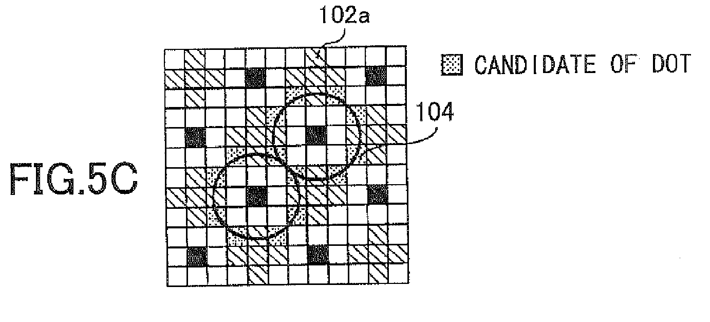
- Each of the positions farthest from the centroid position 103 of the corresponding halftone dot, which position does not overlap with the dot disallowed portions (the blank spots) 102a, is set to be a dot candidate (candidate position) 104 ( FIG. 5C ).
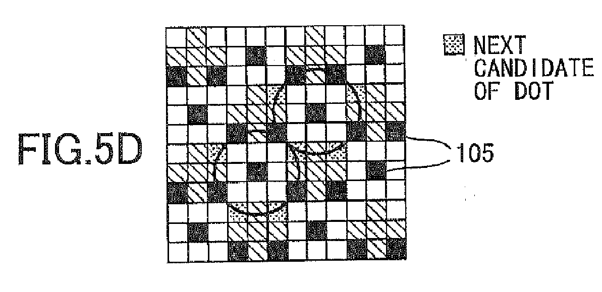
- a corresponding threshold value 105 is generated (sequentially assign values which are greater than the values assigned in ⁇ First threshold value generating process 1>), so that isolated dots are formed (to prevent the dots from neighboring each other) from the dot candidates 104 ( FIG. 5D ).
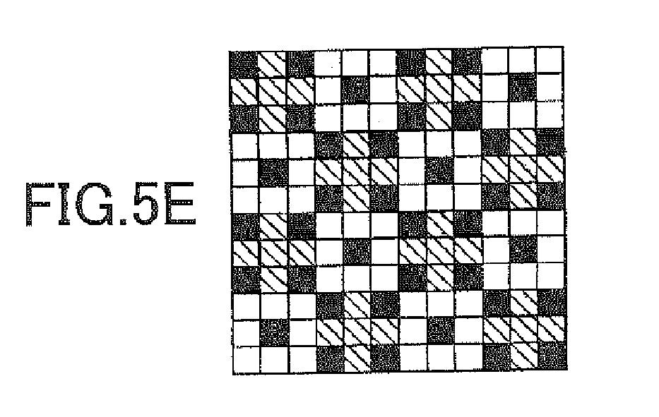
- threshold values are generated so that dots are embedded into remaining candidate positions 104 (sequentially assign values which are greater than the values assigned in ⁇ First threshold value generating process 3>) ( FIG. 5E ).
- the centroid position 103 may be stabilized by embedding another dot in the vicinity of the dot which is embedded into the centroid position 103.
- Threshold values are generated so that dots are embedded into the outline positions of the halftone dots (sequentially assign values which are greater than the corresponding values assigned in ⁇ First threshold value generating process 4>) ( FIG. 5F ).
- the first threshold value generating process is completed by the above-described generating processes, and subsequently the process proceeds to the second threshold value generating process.
- threshold values are generated by a concentration type dither matrix, so that the blank spots 102 are filled with dots.
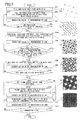
- FIG. 6 shows a flowchart of a first example of the dither matrix generating method according to the embodiment.
- an n-gradation level dither matrix is generated. While sequentially increasing a gradation level one gradation level by one gradation level, threshold values are generated under corresponding determination conditions.
- step 201 as shown in (a) of FIG. 6 , dots are embedded into the centroid positions 103 of the corresponding halftone dots.
- step 202 as shown in (b) of FIG. 6 , each of the positions farthest from the centroid position 103 of the corresponding halftone dot is filled with a corresponding isolated dot.
- step 203 a gradation value is incremented by one, and the processes of steps 202 and 203 are repeated until there are no positions which are farthest from the corresponding centroid positions 103, and which can be filled with corresponding isolated dots.
- each of the remaining positions farthest from the corresponding centroid position 103 is filled with a dot.
- the gradation value is incremented by one, and the processes of steps 205 and 206 are repeated until there are no positions which are farthest from the corresponding centroid positions 103 and which can be filled with corresponding dots.
- each of outlines of the corresponding halftone dot is filled with dots, as shown in (d) of FIG. 6 .
- the gradation value is incremented by one, and the processes of steps 208 and 209 are repeated until all the outlines are filled with dots.
- step 212 When all the outlines are filled with dots (yes at step 210), and when there is a blank spot inside the corresponding outline (yes at step 211), the blank spot is filled with a dot (step 212).
- step 213 the gradation value is incremented by one, and the processes of steps 212 and 213 are repeated until all the blank spots inside the corresponding outlines are filled with dots.
- step 214 threshold values are generated so that blank spots are filled with dots by using a concentration type dither matrix, as shown in (e) of FIG. 6 .
- step 215 the gradation value is incremented by one. When the gradation value n becomes greater than a predetermined gradation level (e.g., 576) (yes at step 216), the process is terminated.
- a predetermined gradation level e.g., 576
- FIG. 7 shows a flowchart of a second example of the dither matrix generating method according to the embodiment.
- FIG. 7 shows an example in which the vicinity of a centroid position 103 of the corresponding halftone dot 101a may not be filled with an isolated dot, due to the size of the halftone dot 101a or the size of the matrix.
- the process of FIG. 7 is different from that of FIG. 6 in step 205a ((c) of FIG. 7 ).
- the vicinity of the centroid position 103 of the corresponding halftone dot 101a (which is the neighborhood of the centroid position 103) is filled with neighboring four dots.
- the other processes at the corresponding steps are the same as those of FIG. 6 .
- the remaining positions farthest from the corresponding centroid position 103 and the vicinity of the corresponding centroid position 103 may be alternately filled with dots.
- threshold values can be generated by the second example of the dither matrix generating method, which is shown in FIG. 7 .
- the second example of the dither matrix generating method which is shown in FIG. 7 .
- a dither matrix for each color version is generated by the dither matrix generating method according to the embodiment.
- the threshold values of the corresponding dither matrices, which are generated as described above, are normalized in accordance with an input gradation value.
- the dither matrix generating method is based on the concentration type dither matrix. Accordingly, even if the size of the matrix is enlarged, the printing speed may not be reduced. In addition, since the memory capacity need not be increased, the cost may not be increased.
- the reference value of the halftone dot area ratio is set to be the halftone dot area ratio at the moment at which the halftone dots of the concentration type dither matrix contact each other.
- the process prior to achieving the reference value is defined to be the first threshold value generating step, and breaking of a fine line is reduced. Once the halftone dots contact each other, a file line may not be broken.
- the process after achieving the reference value is defined to be the second threshold value generating step, and the dot reproducibility is improved by using the concentration type dither matrix. In this manner, breaking of a fine line is reduced, and at the same time image quality is enhanced.
- the dither matrix generating method is not limited to the above-described embodiment.
- the dither matrix generating method can be achieved by using a computer having a generic configuration including a CPU, a memory, and the like.
- the scope of the present invention also includes a program that causes a computer to perform the dither matrix generating method according to the embodiment, and a non-transitory storage medium storing a program that causes a computer to perform the dither matrix generating method according to the embodiment.
Landscapes
- Engineering & Computer Science (AREA)
- Multimedia (AREA)
- Signal Processing (AREA)
- General Engineering & Computer Science (AREA)
- Physics & Mathematics (AREA)
- General Physics & Mathematics (AREA)
- Theoretical Computer Science (AREA)
- Facsimile Image Signal Circuits (AREA)
- Image Processing (AREA)
Abstract


Description
- The present invention relates to a dither matrix generating method, an image processing method, an image processing device, a program, and a non-transitory storage medium storing a program.
- In a printing device that prints an image by forming dots on a printing medium, since a number of available gradation values for a dot is limited relative to a number of gradation values which can be input, gradation is expressed by halftone processing.
- As an example of the halftone processing, a dithering method can be considered. In the dithering method, a halftone is reproduced by a combination of density gradation (intensity modulation) and area gradation (area modulation), for which a number of levels is fewer than that of the original (cf. Patent Document 1 (Japanese Unexamined Patent Publication No.
2003-152999 - A concentration type dither matrix is often used in halftone processing, for which a dither method according to related art is applied. The concentration type dither matrix is often used because it demonstrates good dot reproducibility and high image quality. However, when the concentration type dither matrix is utilized in a low density portion, a gap tends to be generated between neighboring dots, and a fine line tends to be broken. In this regard, by using distributed dithering or non-periodic dithering, breaking of a fine line has been reduced.
- However, an effect of reducing breaking of a fine line is not so strong for the distributed dithering. In addition, the distributed dithering may cause a color shift, for example, and may lower image quality. For the non-periodic dithering, a size of a matrix may be increased. Accordingly, printing speed may be reduced, and cost may be increased due to an increase of required memory capacity.
- An embodiment of the present invention has been developed in view of the above-described problems. It is desirable to provide a dither matrix generating method, which can reduce breaking of a fine line and which can enhance image quality. It is also desirable to provide an image processing method; an image processing device; and a program, in which the above-described dither matrix is utilized.
- According to an aspect of the present invention, there is provided a dither matrix generating method. In the method, halftone dots are formed by growing corresponding dots. The method includes a first generating step of generating first threshold values of a dither matrix, so that the dots grow until a predetermined halftone dot area ratio is achieved, wherein, when the predetermined halftone dot area ratio is achieved, the halftone dots contact each other; and a second generating step of generating second threshold values of the dither matrix, so that the dots grow beyond the predetermined halftone dot area ratio.
- According to the embodiment of the present invention, breaking of the fine line can be reduced, and, at the same time, the image quality can be enhanced.
- Other objects, features and advantages of the present invention will become more apparent from the following detailed description when read in conjunction with the accompanying drawings.
-
-
FIGS. 1A - 1E show examples of half-toning by using a concentration type dither matrix; -
FIG. 2 is a diagram showing an example of a halftone dot area ratio of halftone dots, with which a fine line tends not to be broken; -
FIG. 3 shows an example of half-toning by using dithering for reducing breaking of a fine line according to an embodiment of the present invention; -
FIG. 4 shows a configuration of an image processing device according to the embodiment; -
FIGS. 5A - 5F are diagrams illustrating a dither matrix generating method according to the embodiment; -
FIG. 6 shows a flowchart of a first example of the dither matrix generating method according to the embodiment; and -
FIG. 7 shows a flowchart of a second example of the dither matrix generating method according to the embodiment. - Hereinafter, an embodiment of the present invention is explained in detail by referring to the accompanying drawings. According to the embodiment, a reference value of a halftone dot area ratio is set to be the halftone dot area ratio at a moment at which halftone dots of a concentration type dither matrix contact each other. A process prior to achieving the reference value is defined to be a first threshold value generating step, and breaking of a fine line is reduced. Once the halftone dots contact each other, a fine line is not to be broken after that. Accordingly, the process subsequent to achieving the reference value is defined to be a second threshold value generating step. In the second threshold value generating step, dot reproducibility is improved and image quality is enhanced by using a concentration type dither matrix.
- In a printing device that prints an image by forming dots on a printing medium, since a number of available gradation values is limited relative to a number of gradation values which can be input, gradation is expressed by halftone processing.
FIGS. 1A - 1E show examples of half-toning to which concentration type dithering is applied. InFIG. 1A , since the area ratio of the halftone dots is small, the density is low. The density increases in an order of 1B, 1C, 1D, and 1E. - In the concentration type dithering, since dots are formed while concentrating the dots, dot reproducibility is good and image quality is high. However, in a low density portion, since a gap tends to be formed between dots, a fine line tends to be broken. As the area ratio of the halftone dots is increased while applying the concentration type dithering, the concentrated dots grow, and thereby a single large halftone dot is formed.
-
FIG. 2 shows an example of a halftone dot area ratio of halftone dots, with which a fine line tends not to be broken. In the example ofFIG. 2 , halftone dots, which become large, contact each other. When the halftone dots contact each other in this manner, a gap may not be generated between the halftone dots. Accordingly, a fine line may not be broken. -
FIG. 3 shows an example of half-toning, for which dithering according to the embodiment is applied. The dithering according to the embodiment reduces breaking of a fine line.FIG. 3 shows that, in the halftone processing prior to achieving the halftone area dot ratio with which a fine line tends not to be broken (cf.FIG. 2 ), dots are dispersed as much as possible. By doing this, some dots are generated at corresponding positions, at which a fine line would be broken, if the concentration type dithering were applied. In this manner, a fine line tends not to be broken in the halftone processing prior to achieving the halftone area dot ratio with which a fine line tends not to be broken. For the halftone processing subsequent to achieving the halftone area dot ratio with which a fine line tends not to be broken, dots are stabilized and image quality is enhanced by using concentration type dithering. -
FIG. 4 shows a configuration of an image processing device according to the embodiment. InFIG. 4 , the reference numeral 1 denotes input gradation data; thereference numeral 2 denotes a comparator; thereference numeral 3 denotes a dither matrix generating unit; thereference numeral 4 denotes a dither matrix storage unit; and the reference numeral 5 denotes a halftone image. A dither matrix which is generated by the dithermatrix generating unit 3 is stored in the dithermatrix storage unit 4. Thecomparator 2 compares each of pixel values of the input gradation data 1 with a corresponding threshold value, which is read out from the dithermatrix storage unit 4, and thecomparator 2 outputs a halftone image (binary values or small values). - Next, a dither matrix generating method according to the embodiment is concretely explained. First, a concentration type dither matrix is utilized, and a halftone dot area ratio at a moment at which halftone dots contact each other is set to be a reference value. A threshold value generating process prior to the halftone dot area ratio achieving the reference value is defined to be a first threshold value generating process. In the first threshold value generating process, threshold values are generated by using a plurality of threshold value generating methods. A threshold value generating process subsequent to the halftone dot area ratio achieving the reference value is defined to be a second threshold value generating process. In the second threshold value generating process, a concentration type dither matrix is utilized.
FIGS. 5A - 5F are diagrams illustrating the dither matrix generating method according to the embodiment. - Dots are grown by using the concentration type dither matrix in which predetermined threshold values are arranged (e.g., dither matrices corresponding to
FIGS. 1A - 1E are prepared in a memory), until the halftone dots contact each other (FIG. 5A ). InFIG. 5A , the reference numeral 101 denotes a halftone dot and thereference numeral 102 denotes a blank spot (dots for which the binary value is 0). - All of the threshold values are cleared for the concentration type dither matrix, with which the dots are grown as described above. As shown in
FIG. 5B , a position of each of theblank spots 102 is stored as a dot disallowedportion 102a in the memory (in the first threshold value generating process, it is disallowed to use the dot disallowedportion 102a). Further, a centroid position (geometric center) 103 of each of thehalftone dots 101a is recorded, while assuming that the corresponding dot grows to be a single large halftone dot. Then, threshold values are generated so that the minimum dots occur at correspondingcentroid positions 103 of thehalftone dots 101a (values are assigned in an ascending order from the minimum value of 1). Here, instead of clearing the threshold values as described above, the threshold values may be overwritten. - Each of the positions farthest from the
centroid position 103 of the corresponding halftone dot, which position does not overlap with the dot disallowed portions (the blank spots) 102a, is set to be a dot candidate (candidate position) 104 (FIG. 5C ). - For each
candidate position 104, acorresponding threshold value 105 is generated (sequentially assign values which are greater than the values assigned in <First threshold value generating process 1>), so that isolated dots are formed (to prevent the dots from neighboring each other) from the dot candidates 104 (FIG. 5D ). - After completing embedding the isolated dots, threshold values are generated so that dots are embedded into remaining candidate positions 104 (sequentially assign values which are greater than the values assigned in <First threshold
value generating process 3>) (FIG. 5E ). At this time, if a single isolated point is insufficient for filling thecentroid position 103, thecentroid position 103 may be stabilized by embedding another dot in the vicinity of the dot which is embedded into thecentroid position 103. - Threshold values are generated so that dots are embedded into the outline positions of the halftone dots (sequentially assign values which are greater than the corresponding values assigned in <First threshold
value generating process 4>) (FIG. 5F ). - The first threshold value generating process is completed by the above-described generating processes, and subsequently the process proceeds to the second threshold value generating process. In the second threshold value generating process, threshold values are generated by a concentration type dither matrix, so that the
blank spots 102 are filled with dots. -
FIG. 6 shows a flowchart of a first example of the dither matrix generating method according to the embodiment. InFIG. 6 , an n-gradation level dither matrix is generated. While sequentially increasing a gradation level one gradation level by one gradation level, threshold values are generated under corresponding determination conditions. The number of the gradation levels depends on a size of the dither matrix. For example, when the size of the dither matrix is 24 × 24, the number of the gradation levels is n = 24 × 24 = 576. - At
step 201, as shown in (a) ofFIG. 6 , dots are embedded into the centroid positions 103 of the corresponding halftone dots. Atstep 202, as shown in (b) ofFIG. 6 , each of the positions farthest from thecentroid position 103 of the corresponding halftone dot is filled with a corresponding isolated dot. Atstep 203, a gradation value is incremented by one, and the processes ofsteps centroid positions 103, and which can be filled with corresponding isolated dots. - When there are no positions which can be filled with the corresponding isolated dots (yes at step 204), as shown in (c) of
FIG. 6 , each of the remaining positions farthest from the correspondingcentroid position 103 is filled with a dot. Atstep 206, the gradation value is incremented by one, and the processes ofsteps centroid positions 103 and which can be filled with corresponding dots. - When all the positions farthest from the corresponding
centroid positions 103 are filled with corresponding dots (yes at step 207), atstep 208, each of outlines of the corresponding halftone dot is filled with dots, as shown in (d) ofFIG. 6 . Atstep 209, the gradation value is incremented by one, and the processes ofsteps - When all the outlines are filled with dots (yes at step 210), and when there is a blank spot inside the corresponding outline (yes at step 211), the blank spot is filled with a dot (step 212). At
step 213, the gradation value is incremented by one, and the processes ofsteps step 214, threshold values are generated so that blank spots are filled with dots by using a concentration type dither matrix, as shown in (e) ofFIG. 6 . Atstep 215, the gradation value is incremented by one. When the gradation value n becomes greater than a predetermined gradation level (e.g., 576) (yes at step 216), the process is terminated. -
FIG. 7 shows a flowchart of a second example of the dither matrix generating method according to the embodiment.FIG. 7 shows an example in which the vicinity of acentroid position 103 of the correspondinghalftone dot 101a may not be filled with an isolated dot, due to the size of thehalftone dot 101a or the size of the matrix. The process ofFIG. 7 is different from that ofFIG. 6 instep 205a ((c) ofFIG. 7 ). Atstep 205a, the vicinity of thecentroid position 103 of the correspondinghalftone dot 101a (which is the neighborhood of the centroid position 103) is filled with neighboring four dots. The other processes at the corresponding steps are the same as those ofFIG. 6 . Here, after the positions farthest from the correspondingcentroid positions 103 are filled with the isolated dots, the remaining positions farthest from the correspondingcentroid position 103 and the vicinity of the correspondingcentroid position 103 may be alternately filled with dots. - Since the dot reproducibility differs depending on an image forming device, if an unnecessary pattern is conspicuous, threshold values can be generated by the second example of the dither matrix generating method, which is shown in
FIG. 7 . Depending on the size of thehalftone dot 101a, it is possible that some blank spots remain after filling the outlines with the dots. In such a case, inside each of the outlines may be filled with dots, and subsequently remaining blank spots may be filled with dots by using a concentration type dither matrix. - A dither matrix for each color version is generated by the dither matrix generating method according to the embodiment. The threshold values of the corresponding dither matrices, which are generated as described above, are normalized in accordance with an input gradation value.
- As described above, the dither matrix generating method according to the embodiment is based on the concentration type dither matrix. Accordingly, even if the size of the matrix is enlarged, the printing speed may not be reduced. In addition, since the memory capacity need not be increased, the cost may not be increased. In the dither matrix generating method according to the embodiment, the reference value of the halftone dot area ratio is set to be the halftone dot area ratio at the moment at which the halftone dots of the concentration type dither matrix contact each other. The process prior to achieving the reference value is defined to be the first threshold value generating step, and breaking of a fine line is reduced. Once the halftone dots contact each other, a file line may not be broken. Thus, the process after achieving the reference value is defined to be the second threshold value generating step, and the dot reproducibility is improved by using the concentration type dither matrix. In this manner, breaking of a fine line is reduced, and at the same time image quality is enhanced.
- The dither matrix generating method is not limited to the above-described embodiment. The dither matrix generating method can be achieved by using a computer having a generic configuration including a CPU, a memory, and the like. The scope of the present invention also includes a program that causes a computer to perform the dither matrix generating method according to the embodiment, and a non-transitory storage medium storing a program that causes a computer to perform the dither matrix generating method according to the embodiment.
- The present invention is not limited to the specifically disclosed embodiment, and variations and modifications may be made without departing from the scope of the present invention.
- The present application is based on and claims the benefit of priority of Japanese Priority Application No.
2013-023487 filed on February 8, 2013
Claims (8)
- A dither matrix generating method in which halftone dots are formed by growing corresponding dots, the dither matrix generating method comprising:a first generating step of generating first threshold values of a dither matrix, so that the dots are grown until a predetermined halftone dot area ratio is achieved, wherein, when the predetermined halftone dot area ratio is achieved, the halftone dots contact each other; anda second generating step of generating second threshold values of the dither matrix, so that the dots grow beyond the predetermined halftone dot area ratio.
- The dither matrix generating method according to claim 1,
wherein the first generating step includes
a first process of growing the dots by using a predetermined dither matrix, recording centroid positions of the corresponding halftone dots at a moment at which the halftone dots contact each other and blank dot positions at which dots do not grow, and assigning threshold values to the corresponding centroid positions of the halftone dots in an ascending order from a smallest value among the threshold values;
a second process of assigning, in an ascending order, threshold values greater than the threshold values of the first process to positions at which corresponding isolated dots are to be generated, wherein the positions are included in candidate positions, the candidate positions being defined to be positions farthest from the corresponding centroid positions, except for the blank dot positions;
a third process of assigning threshold values greater than the threshold values of the second process in an ascending order to remaining candidate positions; and
a fourth process of assigning threshold values greater than the threshold values of the third process in an ascending order to outline positions of the corresponding halftone dots. - The dither matrix generating method according to claim 2,
wherein the third process includes a process of assigning a plurality of neighboring threshold values in an ascending order to vicinities of the corresponding centroid positions of the halftone dots. - The dither matrix generating method according to claim 1,
wherein the second generating step includes a process of generating the second threshold values of the dither matrix, wherein the second threshold values are for forming dot-concentration type halftone dots. - An image processing method of outputting a halftone image by using the dither matrix generated by the dither matrix generating method according to any one of claims 1 to 4.
- An image processing device configured to output a halftone image by using the dither matrix generated by the dither matrix generating method according to any one of claims 1 to 4.
- A program which causes a computer to perform the dither matrix generating method according to any one of claims 1 to 4.
- A non-transitory computer readable storage medium storing a program which causes a computer to perform the dither matrix generating method according to any one of claims 1 to 4.
Applications Claiming Priority (1)
| Application Number | Priority Date | Filing Date | Title |
|---|---|---|---|
| JP2013023487A JP6119280B2 (en) | 2013-02-08 | 2013-02-08 | Dither matrix generation method, image processing method, image processing apparatus, and program |
Publications (2)
| Publication Number | Publication Date |
|---|---|
| EP2765764A1 true EP2765764A1 (en) | 2014-08-13 |
| EP2765764B1 EP2765764B1 (en) | 2018-06-13 |
Family
ID=49876375
Family Applications (1)
| Application Number | Title | Priority Date | Filing Date |
|---|---|---|---|
| EP13197191.3A Active EP2765764B1 (en) | 2013-02-08 | 2013-12-13 | Dither matrix generating method, image processing method, image processing device, program, and non-transitory storage medium storing program |
Country Status (3)
| Country | Link |
|---|---|
| US (1) | US9036214B2 (en) |
| EP (1) | EP2765764B1 (en) |
| JP (1) | JP6119280B2 (en) |
Cited By (1)
| Publication number | Priority date | Publication date | Assignee | Title |
|---|---|---|---|---|
| CN105827895A (en) * | 2015-01-23 | 2016-08-03 | 富士施乐株式会社 | Dot area extraction method, and dot area extraction device |
Families Citing this family (6)
| Publication number | Priority date | Publication date | Assignee | Title |
|---|---|---|---|---|
| GB2522422A (en) * | 2014-01-22 | 2015-07-29 | Landa Corp Ltd | Apparatus and method for half-toning |
| JP6531471B2 (en) * | 2014-07-29 | 2019-06-19 | 株式会社リコー | Image forming apparatus, dither pattern generating apparatus, and dither pattern generating method |
| US9787873B2 (en) * | 2015-07-07 | 2017-10-10 | Ricoh Company, Ltd. | Halftone dot screen generation with conditional arrangement of growth centers to form dot blocks and bridges connecting adjacent dot blocks |
| US10477068B2 (en) | 2016-03-18 | 2019-11-12 | Ricoh Company, Ltd. | Image processing apparatus for primary color and spot halftoning |
| US10410100B1 (en) | 2017-11-14 | 2019-09-10 | Landa Corporation Ltd. | AM Screening |
| JP7608743B2 (en) | 2020-07-15 | 2025-01-07 | 株式会社リコー | Image forming apparatus, correction data derivation method and program |
Citations (2)
| Publication number | Priority date | Publication date | Assignee | Title |
|---|---|---|---|---|
| JPH01249350A (en) * | 1988-03-30 | 1989-10-04 | Brother Ind Ltd | Halftone image reproduction method |
| US5617123A (en) * | 1987-05-20 | 1997-04-01 | Canon Kabushiki Kaisha | Image processing method utilizing multiple binarizing and recording agent depositing steps |
Family Cites Families (25)
| Publication number | Priority date | Publication date | Assignee | Title |
|---|---|---|---|---|
| JPH01243782A (en) * | 1988-03-25 | 1989-09-28 | Fuji Xerox Co Ltd | Gradation display method in picture output device |
| US4924301A (en) * | 1988-11-08 | 1990-05-08 | Seecolor Corporation | Apparatus and methods for digital halftoning |
| JPH0937076A (en) * | 1995-07-17 | 1997-02-07 | Brother Ind Ltd | Printing equipment |
| JPH10166658A (en) * | 1996-12-06 | 1998-06-23 | Seiko Epson Corp | Image forming device |
| JP4108262B2 (en) * | 1999-10-18 | 2008-06-25 | 富士フイルム株式会社 | Image processing method and image processing apparatus |
| JP2001326817A (en) * | 2000-05-15 | 2001-11-22 | Matsushita Electric Ind Co Ltd | Image processing device |
| JP3932161B2 (en) | 2000-06-19 | 2007-06-20 | 株式会社リコー | Image processing apparatus and method |
| JP2003152999A (en) | 2001-11-13 | 2003-05-23 | Matsushita Electric Ind Co Ltd | Image processing method and image processing apparatus |
| US7239429B2 (en) * | 2003-05-29 | 2007-07-03 | Seiko Epson Corporation | Method and apparatus for generating dispersed cluster screen |
| JP4204000B2 (en) * | 2003-12-02 | 2009-01-07 | 株式会社リコー | Dither matrix creation method and apparatus, image processing method and apparatus, image forming method and apparatus, program, and recording medium |
| US7069851B2 (en) * | 2004-01-20 | 2006-07-04 | Think Laboratory Co., Ltd. | Gravure printing method and gravure printed item |
| JP4514132B2 (en) * | 2004-05-28 | 2010-07-28 | 大日本スクリーン製造株式会社 | Threshold matrix generation method for halftone image generation, halftone image generation method and apparatus, and threshold matrix |
| JP4678269B2 (en) * | 2005-09-15 | 2011-04-27 | セイコーエプソン株式会社 | Dither matrix generation |
| JP4720490B2 (en) * | 2005-12-22 | 2011-07-13 | セイコーエプソン株式会社 | Dither matrix generation |
| JP2007276449A (en) * | 2006-03-15 | 2007-10-25 | Ricoh Co Ltd | Setting method, image recording apparatus, program, and recording medium |
| JP4240043B2 (en) * | 2006-03-17 | 2009-03-18 | セイコーエプソン株式会社 | Dither matrix generation |
| US7733533B2 (en) * | 2006-04-06 | 2010-06-08 | Infoprint Solutions Company Llc | Generating threshold values in a dither matrix |
| JP2008134280A (en) | 2006-11-27 | 2008-06-12 | Ricoh Co Ltd | Image forming apparatus and image forming method |
| JP4975663B2 (en) * | 2008-03-12 | 2012-07-11 | 大日本スクリーン製造株式会社 | Threshold matrix generation method, halftone image generation method, and halftone image generation apparatus |
| JP4702470B2 (en) * | 2009-03-31 | 2011-06-15 | ブラザー工業株式会社 | Image processing apparatus and dither matrix |
| JP5434819B2 (en) * | 2010-06-28 | 2014-03-05 | ブラザー工業株式会社 | Dither matrix selection device and dither matrix selection program |
| JP5323035B2 (en) * | 2010-12-10 | 2013-10-23 | キヤノン株式会社 | Image forming apparatus and image forming method |
| JP5702621B2 (en) * | 2011-02-10 | 2015-04-15 | 株式会社Screenホールディングス | Image recording apparatus and image recording method |
| JP5824942B2 (en) * | 2011-07-27 | 2015-12-02 | ブラザー工業株式会社 | Dither matrix creation device and dither matrix creation program |
| US8681383B2 (en) * | 2011-12-22 | 2014-03-25 | Xerox Corporation | 2nd generation dot-off-dot stochastic halftone |
-
2013
- 2013-02-08 JP JP2013023487A patent/JP6119280B2/en active Active
- 2013-12-09 US US14/100,258 patent/US9036214B2/en active Active
- 2013-12-13 EP EP13197191.3A patent/EP2765764B1/en active Active
Patent Citations (2)
| Publication number | Priority date | Publication date | Assignee | Title |
|---|---|---|---|---|
| US5617123A (en) * | 1987-05-20 | 1997-04-01 | Canon Kabushiki Kaisha | Image processing method utilizing multiple binarizing and recording agent depositing steps |
| JPH01249350A (en) * | 1988-03-30 | 1989-10-04 | Brother Ind Ltd | Halftone image reproduction method |
Cited By (2)
| Publication number | Priority date | Publication date | Assignee | Title |
|---|---|---|---|---|
| CN105827895A (en) * | 2015-01-23 | 2016-08-03 | 富士施乐株式会社 | Dot area extraction method, and dot area extraction device |
| CN105827895B (en) * | 2015-01-23 | 2019-02-19 | 富士施乐株式会社 | Dot area extraction method and dot area extraction device |
Also Published As
| Publication number | Publication date |
|---|---|
| JP6119280B2 (en) | 2017-04-26 |
| EP2765764B1 (en) | 2018-06-13 |
| US9036214B2 (en) | 2015-05-19 |
| US20140226187A1 (en) | 2014-08-14 |
| JP2014155058A (en) | 2014-08-25 |
Similar Documents
| Publication | Publication Date | Title |
|---|---|---|
| EP2765764B1 (en) | Dither matrix generating method, image processing method, image processing device, program, and non-transitory storage medium storing program | |
| US10043118B2 (en) | Image processing apparatus, image processing method, printing medium and storage medium | |
| US8649061B2 (en) | Laser print apparatus with dual halftones | |
| JP7071564B2 (en) | Image processing system, image processing method, and image processing device | |
| JP7005314B2 (en) | Image processing equipment, image processing methods, and programs | |
| JP4743596B2 (en) | Image processing apparatus, method, program, and recording medium | |
| US11818319B2 (en) | Information processing apparatus, image processing method, and medium | |
| JP5282800B2 (en) | Image processing apparatus and program | |
| US20060285167A1 (en) | Image processing method and a recording medium storing image processing program | |
| JP4050382B2 (en) | Multi-value image smoothing apparatus and image forming apparatus | |
| JP6525518B2 (en) | Image processing apparatus, image processing method and program | |
| US10855883B2 (en) | Image processing apparatus for performing edge correction of image, method of controlling the same, and storage medium | |
| US10404892B2 (en) | Image forming apparatus for outputting a halftone image and image forming method | |
| US9396418B2 (en) | Information processing apparatus, information processing method, and storage medium for processing an image and a pattern included in an XOR-and-XOR rendering command set | |
| JP6061654B2 (en) | Image processing apparatus, image processing method, and computer program | |
| JP2009135637A (en) | Image processor, image processing method and program | |
| JP2002185787A (en) | Dither pattern generation method and dither pattern generation device | |
| JP2006197411A (en) | Halftone screening method and printer | |
| JP2006035810A (en) | Laser printer | |
| JP2006246293A (en) | Image processing apparatus and image processing program | |
| JP2878695B2 (en) | Image processing apparatus and multi-value image estimation method | |
| HK1091633A (en) | Laser print apparatus with dual halftones | |
| KR20010094873A (en) | Apparatus and method for compensation image in 1bit-gray of laser printer |
Legal Events
| Date | Code | Title | Description |
|---|---|---|---|
| PUAI | Public reference made under article 153(3) epc to a published international application that has entered the european phase |
Free format text: ORIGINAL CODE: 0009012 |
|
| 17P | Request for examination filed |
Effective date: 20131213 |
|
| AK | Designated contracting states |
Kind code of ref document: A1 Designated state(s): AL AT BE BG CH CY CZ DE DK EE ES FI FR GB GR HR HU IE IS IT LI LT LU LV MC MK MT NL NO PL PT RO RS SE SI SK SM TR |
|
| AX | Request for extension of the european patent |
Extension state: BA ME |
|
| GRAP | Despatch of communication of intention to grant a patent |
Free format text: ORIGINAL CODE: EPIDOSNIGR1 |
|
| INTG | Intention to grant announced |
Effective date: 20180103 |
|
| GRAS | Grant fee paid |
Free format text: ORIGINAL CODE: EPIDOSNIGR3 |
|
| GRAA | (expected) grant |
Free format text: ORIGINAL CODE: 0009210 |
|
| AK | Designated contracting states |
Kind code of ref document: B1 Designated state(s): AL AT BE BG CH CY CZ DE DK EE ES FI FR GB GR HR HU IE IS IT LI LT LU LV MC MK MT NL NO PL PT RO RS SE SI SK SM TR |
|
| REG | Reference to a national code |
Ref country code: GB Ref legal event code: FG4D |
|
| REG | Reference to a national code |
Ref country code: CH Ref legal event code: EP Ref country code: AT Ref legal event code: REF Ref document number: 1009706 Country of ref document: AT Kind code of ref document: T Effective date: 20180615 |
|
| REG | Reference to a national code |
Ref country code: IE Ref legal event code: FG4D |
|
| REG | Reference to a national code |
Ref country code: DE Ref legal event code: R096 Ref document number: 602013038810 Country of ref document: DE |
|
| REG | Reference to a national code |
Ref country code: NL Ref legal event code: MP Effective date: 20180613 |
|
| REG | Reference to a national code |
Ref country code: LT Ref legal event code: MG4D |
|
| PG25 | Lapsed in a contracting state [announced via postgrant information from national office to epo] |
Ref country code: NO Free format text: LAPSE BECAUSE OF FAILURE TO SUBMIT A TRANSLATION OF THE DESCRIPTION OR TO PAY THE FEE WITHIN THE PRESCRIBED TIME-LIMIT Effective date: 20180913 Ref country code: FI Free format text: LAPSE BECAUSE OF FAILURE TO SUBMIT A TRANSLATION OF THE DESCRIPTION OR TO PAY THE FEE WITHIN THE PRESCRIBED TIME-LIMIT Effective date: 20180613 Ref country code: CY Free format text: LAPSE BECAUSE OF FAILURE TO SUBMIT A TRANSLATION OF THE DESCRIPTION OR TO PAY THE FEE WITHIN THE PRESCRIBED TIME-LIMIT Effective date: 20180613 Ref country code: BG Free format text: LAPSE BECAUSE OF FAILURE TO SUBMIT A TRANSLATION OF THE DESCRIPTION OR TO PAY THE FEE WITHIN THE PRESCRIBED TIME-LIMIT Effective date: 20180913 Ref country code: ES Free format text: LAPSE BECAUSE OF FAILURE TO SUBMIT A TRANSLATION OF THE DESCRIPTION OR TO PAY THE FEE WITHIN THE PRESCRIBED TIME-LIMIT Effective date: 20180613 Ref country code: SE Free format text: LAPSE BECAUSE OF FAILURE TO SUBMIT A TRANSLATION OF THE DESCRIPTION OR TO PAY THE FEE WITHIN THE PRESCRIBED TIME-LIMIT Effective date: 20180613 Ref country code: LT Free format text: LAPSE BECAUSE OF FAILURE TO SUBMIT A TRANSLATION OF THE DESCRIPTION OR TO PAY THE FEE WITHIN THE PRESCRIBED TIME-LIMIT Effective date: 20180613 |
|
| PG25 | Lapsed in a contracting state [announced via postgrant information from national office to epo] |
Ref country code: LV Free format text: LAPSE BECAUSE OF FAILURE TO SUBMIT A TRANSLATION OF THE DESCRIPTION OR TO PAY THE FEE WITHIN THE PRESCRIBED TIME-LIMIT Effective date: 20180613 Ref country code: HR Free format text: LAPSE BECAUSE OF FAILURE TO SUBMIT A TRANSLATION OF THE DESCRIPTION OR TO PAY THE FEE WITHIN THE PRESCRIBED TIME-LIMIT Effective date: 20180613 Ref country code: GR Free format text: LAPSE BECAUSE OF FAILURE TO SUBMIT A TRANSLATION OF THE DESCRIPTION OR TO PAY THE FEE WITHIN THE PRESCRIBED TIME-LIMIT Effective date: 20180914 Ref country code: RS Free format text: LAPSE BECAUSE OF FAILURE TO SUBMIT A TRANSLATION OF THE DESCRIPTION OR TO PAY THE FEE WITHIN THE PRESCRIBED TIME-LIMIT Effective date: 20180613 |
|
| REG | Reference to a national code |
Ref country code: AT Ref legal event code: MK05 Ref document number: 1009706 Country of ref document: AT Kind code of ref document: T Effective date: 20180613 |
|
| PG25 | Lapsed in a contracting state [announced via postgrant information from national office to epo] |
Ref country code: NL Free format text: LAPSE BECAUSE OF FAILURE TO SUBMIT A TRANSLATION OF THE DESCRIPTION OR TO PAY THE FEE WITHIN THE PRESCRIBED TIME-LIMIT Effective date: 20180613 |
|
| PG25 | Lapsed in a contracting state [announced via postgrant information from national office to epo] |
Ref country code: AT Free format text: LAPSE BECAUSE OF FAILURE TO SUBMIT A TRANSLATION OF THE DESCRIPTION OR TO PAY THE FEE WITHIN THE PRESCRIBED TIME-LIMIT Effective date: 20180613 Ref country code: EE Free format text: LAPSE BECAUSE OF FAILURE TO SUBMIT A TRANSLATION OF THE DESCRIPTION OR TO PAY THE FEE WITHIN THE PRESCRIBED TIME-LIMIT Effective date: 20180613 Ref country code: PL Free format text: LAPSE BECAUSE OF FAILURE TO SUBMIT A TRANSLATION OF THE DESCRIPTION OR TO PAY THE FEE WITHIN THE PRESCRIBED TIME-LIMIT Effective date: 20180613 Ref country code: IS Free format text: LAPSE BECAUSE OF FAILURE TO SUBMIT A TRANSLATION OF THE DESCRIPTION OR TO PAY THE FEE WITHIN THE PRESCRIBED TIME-LIMIT Effective date: 20181013 Ref country code: RO Free format text: LAPSE BECAUSE OF FAILURE TO SUBMIT A TRANSLATION OF THE DESCRIPTION OR TO PAY THE FEE WITHIN THE PRESCRIBED TIME-LIMIT Effective date: 20180613 Ref country code: CZ Free format text: LAPSE BECAUSE OF FAILURE TO SUBMIT A TRANSLATION OF THE DESCRIPTION OR TO PAY THE FEE WITHIN THE PRESCRIBED TIME-LIMIT Effective date: 20180613 Ref country code: SK Free format text: LAPSE BECAUSE OF FAILURE TO SUBMIT A TRANSLATION OF THE DESCRIPTION OR TO PAY THE FEE WITHIN THE PRESCRIBED TIME-LIMIT Effective date: 20180613 |
|
| PG25 | Lapsed in a contracting state [announced via postgrant information from national office to epo] |
Ref country code: SM Free format text: LAPSE BECAUSE OF FAILURE TO SUBMIT A TRANSLATION OF THE DESCRIPTION OR TO PAY THE FEE WITHIN THE PRESCRIBED TIME-LIMIT Effective date: 20180613 Ref country code: IT Free format text: LAPSE BECAUSE OF FAILURE TO SUBMIT A TRANSLATION OF THE DESCRIPTION OR TO PAY THE FEE WITHIN THE PRESCRIBED TIME-LIMIT Effective date: 20180613 |
|
| REG | Reference to a national code |
Ref country code: DE Ref legal event code: R097 Ref document number: 602013038810 Country of ref document: DE |
|
| PLBE | No opposition filed within time limit |
Free format text: ORIGINAL CODE: 0009261 |
|
| STAA | Information on the status of an ep patent application or granted ep patent |
Free format text: STATUS: NO OPPOSITION FILED WITHIN TIME LIMIT |
|
| 26N | No opposition filed |
Effective date: 20190314 |
|
| PG25 | Lapsed in a contracting state [announced via postgrant information from national office to epo] |
Ref country code: SI Free format text: LAPSE BECAUSE OF FAILURE TO SUBMIT A TRANSLATION OF THE DESCRIPTION OR TO PAY THE FEE WITHIN THE PRESCRIBED TIME-LIMIT Effective date: 20180613 Ref country code: DK Free format text: LAPSE BECAUSE OF FAILURE TO SUBMIT A TRANSLATION OF THE DESCRIPTION OR TO PAY THE FEE WITHIN THE PRESCRIBED TIME-LIMIT Effective date: 20180613 |
|
| REG | Reference to a national code |
Ref country code: CH Ref legal event code: PL |
|
| PG25 | Lapsed in a contracting state [announced via postgrant information from national office to epo] |
Ref country code: MC Free format text: LAPSE BECAUSE OF FAILURE TO SUBMIT A TRANSLATION OF THE DESCRIPTION OR TO PAY THE FEE WITHIN THE PRESCRIBED TIME-LIMIT Effective date: 20180613 Ref country code: LU Free format text: LAPSE BECAUSE OF NON-PAYMENT OF DUE FEES Effective date: 20181213 |
|
| REG | Reference to a national code |
Ref country code: IE Ref legal event code: MM4A |
|
| REG | Reference to a national code |
Ref country code: BE Ref legal event code: MM Effective date: 20181231 |
|
| PG25 | Lapsed in a contracting state [announced via postgrant information from national office to epo] |
Ref country code: IE Free format text: LAPSE BECAUSE OF NON-PAYMENT OF DUE FEES Effective date: 20181213 |
|
| PG25 | Lapsed in a contracting state [announced via postgrant information from national office to epo] |
Ref country code: BE Free format text: LAPSE BECAUSE OF NON-PAYMENT OF DUE FEES Effective date: 20181231 Ref country code: AL Free format text: LAPSE BECAUSE OF FAILURE TO SUBMIT A TRANSLATION OF THE DESCRIPTION OR TO PAY THE FEE WITHIN THE PRESCRIBED TIME-LIMIT Effective date: 20180613 |
|
| PG25 | Lapsed in a contracting state [announced via postgrant information from national office to epo] |
Ref country code: LI Free format text: LAPSE BECAUSE OF NON-PAYMENT OF DUE FEES Effective date: 20181231 Ref country code: CH Free format text: LAPSE BECAUSE OF NON-PAYMENT OF DUE FEES Effective date: 20181231 |
|
| PG25 | Lapsed in a contracting state [announced via postgrant information from national office to epo] |
Ref country code: MT Free format text: LAPSE BECAUSE OF NON-PAYMENT OF DUE FEES Effective date: 20181213 |
|
| PG25 | Lapsed in a contracting state [announced via postgrant information from national office to epo] |
Ref country code: TR Free format text: LAPSE BECAUSE OF FAILURE TO SUBMIT A TRANSLATION OF THE DESCRIPTION OR TO PAY THE FEE WITHIN THE PRESCRIBED TIME-LIMIT Effective date: 20180613 |
|
| PG25 | Lapsed in a contracting state [announced via postgrant information from national office to epo] |
Ref country code: PT Free format text: LAPSE BECAUSE OF FAILURE TO SUBMIT A TRANSLATION OF THE DESCRIPTION OR TO PAY THE FEE WITHIN THE PRESCRIBED TIME-LIMIT Effective date: 20180613 |
|
| PG25 | Lapsed in a contracting state [announced via postgrant information from national office to epo] |
Ref country code: MK Free format text: LAPSE BECAUSE OF NON-PAYMENT OF DUE FEES Effective date: 20180613 Ref country code: HU Free format text: LAPSE BECAUSE OF FAILURE TO SUBMIT A TRANSLATION OF THE DESCRIPTION OR TO PAY THE FEE WITHIN THE PRESCRIBED TIME-LIMIT; INVALID AB INITIO Effective date: 20131213 |
|
| P01 | Opt-out of the competence of the unified patent court (upc) registered |
Effective date: 20230522 |
|
| PGFP | Annual fee paid to national office [announced via postgrant information from national office to epo] |
Ref country code: DE Payment date: 20251211 Year of fee payment: 13 |
|
| PGFP | Annual fee paid to national office [announced via postgrant information from national office to epo] |
Ref country code: GB Payment date: 20251219 Year of fee payment: 13 |
|
| PGFP | Annual fee paid to national office [announced via postgrant information from national office to epo] |
Ref country code: FR Payment date: 20251223 Year of fee payment: 13 |