EP2765688A2 - Coaxial rotating rectifier package assembly for generator - Google Patents
Coaxial rotating rectifier package assembly for generator Download PDFInfo
- Publication number
- EP2765688A2 EP2765688A2 EP14154185.4A EP14154185A EP2765688A2 EP 2765688 A2 EP2765688 A2 EP 2765688A2 EP 14154185 A EP14154185 A EP 14154185A EP 2765688 A2 EP2765688 A2 EP 2765688A2
- Authority
- EP
- European Patent Office
- Prior art keywords
- ring
- diode
- posts
- pack
- disposed
- Prior art date
- Legal status (The legal status is an assumption and is not a legal conclusion. Google has not performed a legal analysis and makes no representation as to the accuracy of the status listed.)
- Withdrawn
Links
- 239000012212 insulator Substances 0.000 claims description 3
- 239000000919 ceramic Substances 0.000 claims description 2
- 125000006850 spacer group Chemical group 0.000 description 2
- 230000003068 static effect Effects 0.000 description 2
- 230000001360 synchronised effect Effects 0.000 description 2
- 230000004075 alteration Effects 0.000 description 1
- 230000008030 elimination Effects 0.000 description 1
- 238000003379 elimination reaction Methods 0.000 description 1
- 238000000034 method Methods 0.000 description 1
- 238000006467 substitution reaction Methods 0.000 description 1
Images




Classifications
-
- H—ELECTRICITY
- H02—GENERATION; CONVERSION OR DISTRIBUTION OF ELECTRIC POWER
- H02M—APPARATUS FOR CONVERSION BETWEEN AC AND AC, BETWEEN AC AND DC, OR BETWEEN DC AND DC, AND FOR USE WITH MAINS OR SIMILAR POWER SUPPLY SYSTEMS; CONVERSION OF DC OR AC INPUT POWER INTO SURGE OUTPUT POWER; CONTROL OR REGULATION THEREOF
- H02M7/00—Conversion of AC power input into DC power output; Conversion of DC power input into AC power output
- H02M7/003—Constructional details, e.g. physical layout, assembly, wiring or busbar connections
-
- H—ELECTRICITY
- H02—GENERATION; CONVERSION OR DISTRIBUTION OF ELECTRIC POWER
- H02K—DYNAMO-ELECTRIC MACHINES
- H02K11/00—Structural association of dynamo-electric machines with electric components or with devices for shielding, monitoring or protection
- H02K11/04—Structural association of dynamo-electric machines with electric components or with devices for shielding, monitoring or protection for rectification
- H02K11/042—Rectifiers associated with rotating parts, e.g. rotor cores or rotary shafts
-
- H—ELECTRICITY
- H02—GENERATION; CONVERSION OR DISTRIBUTION OF ELECTRIC POWER
- H02M—APPARATUS FOR CONVERSION BETWEEN AC AND AC, BETWEEN AC AND DC, OR BETWEEN DC AND DC, AND FOR USE WITH MAINS OR SIMILAR POWER SUPPLY SYSTEMS; CONVERSION OF DC OR AC INPUT POWER INTO SURGE OUTPUT POWER; CONTROL OR REGULATION THEREOF
- H02M7/00—Conversion of AC power input into DC power output; Conversion of DC power input into AC power output
- H02M7/02—Conversion of AC power input into DC power output without possibility of reversal
- H02M7/04—Conversion of AC power input into DC power output without possibility of reversal by static converters
- H02M7/06—Conversion of AC power input into DC power output without possibility of reversal by static converters using discharge tubes without control electrode or semiconductor devices without control electrode
Definitions
- One failure mode results from an electrical static discharge event from the rotor frame to the isolated rotor circuit.
- the rotor frame has an opening through which a bus bar extends.
- the bus bar which is electrically connected to the rotor circuit, is electrically insulated from the rotor frame with an insulator.
- the diode pack 200 includes an outer DC ring 202 and inner DC ring 204 which are coaxially disposed about a central oil tube 224 and inside the rotor shaft 106.
- the outer DC ring 202 is in direct contact with the shaft for static grounding.
- the outer DC ring 202 and the inner DC ring 204 are separated by spacer 212 and by a ceramic resistor disk 214.
- the diode pack 200 also includes a cover 216 that is affixed to the outer DC ring 202 by a plurality of bolts 220 and washers 218.
- the diode pack 200 also includes a plurality of diodes 206 which are disposed between the outer DC ring 202 and the inner DC ring 204.
- the diode pack 200 includes three pairs of radially stacked diodes 206 and a diode connection plate 226 disposed between each of the pairs of radially stacked diodes 206.
- the diode connection plates 226 are each affixed to an AC post 210.
- the diode pack 200 includes one or more DC posts 208 which are affixed to the inner DC ring 204 and outer DC ring 202.
- the diodes 206 and plates 226 may be held in place by a spring clip 222.
- FIG. 2B a top view of a diode pack 200 in accordance with one embodiment is shown.
- the diode pack 200 includes three AC posts 210 and two DC posts 208 which extend from one end of the diode pack 200 in the direction of the central oil tube 224.
- the diode pack 200 includes three pairs of diodes 206 which are each separated by a diode connection plate 226.
- the diode pack 200 includes an inner DC ring 204 and an outer DC ring 202, which are separated by a spacer 212.
- connection block 300 in accordance with one embodiment is shown.
- the connection block 300 is configured to attach the end of the diode pack shown in FIG. 2B .
- the connection block 300 is designed to receive the AC posts and DC posts from the diode pack and to provide connections 304 to the AC posts and DC posts.
- the connection block 300 also includes an aperture 302 configured to receive the oil tube.
- connection block 300 in accordance with one embodiment is shown.
- the end of the connection block 300 shown is configured to attach the end of the diode pack shown in FIG. 2B .
- the connection block 300 is designed to receive the AC posts of the diode pack in AC connectors 306 and DC posts of the diode pack in DC connectors 308.
- the connection block 300 also includes an aperture 302 configured to receive the oil tube.
- connection block 300 is designed to receive the AC posts of the diode pack in AC connectors 306 and DC posts of the diode pack in DC connectors 308.
- Both the AC connectors 306 and DC connectors 308 include a powerband 310 configured to fittingly receive an AC post or DC post from the diode pack.
- the terminals 304 also include a threaded portion, or helicoil, 312 which is configured to receive a bolt or other attachment means.
- the rectifier assembly 400 includes a diode pack 402 and a connection block 404.
- the connection block 404 includes a plurality of terminals 406 that are configured to receive bolts 408, which secure the connection block 404 to the rectifier rotor assembly 400 and provide electrical connections to the diode pack 402.
- the diode pack 402 includes an outer DC ring 410 and an inner DC ring 414 and a plurality of diodes 412 disposed between the rings.
- the diodes 412 are disposed in radially stacked pairs with a diode connection plate 420 disposed between each pair of diodes.
- the diode pack 402 also includes one or more DC posts 418 that are in electrical communication with the inner DC ring 414 and outer DC ring 410. In one embodiment, the inner DC ring 414 and outer DC ring 410 are separated by an insulator 426.
- the diode pack 402 also includes a cover 422 that is secured to the outer DC ring 410 via one or more bolts 424.
- a diode pack is provided for a rotating rectifier assembly.
- the diode pack is configured to have two coaxial DC rings and radially stacked pairs of diodes disposed between the DC rings. By radially stacking diode pairs, as opposed to the traditional placement of adjacent along the rotor shaft of the rectifier assembly, the length of the diode pack can be reduced.
- the diode pack is configured to pass electrical signals through rotor shaft and incorporates diode package grounding similar to schemes described in patent U.S. Patent 8,063,522.
- the configuration of the diode pack specifically two co-axially located DC rings and three sets of radially stacked diodes, allows assembly with elimination of numerous fasteners, and reduced part count.
Landscapes
- Engineering & Computer Science (AREA)
- Power Engineering (AREA)
- Synchronous Machinery (AREA)
Abstract
Description
- The present disclosure relates to the field of generators, and more specifically, to a coaxial rotating rectifier assembly for a three stage wound field synchronous generator.
- A three stage wound field synchronous generator includes an exciter and a main machine. Both exciter and main machine include a stator fixed relative to a housing and a rotor rotatable about an axis relative to the stators. The rotor includes a rotor frame carrying a rotating circuit that includes a main field, an exciter armature and a rectifier assembly, which has diodes. While rotating, DC voltage is applied to the exciter stator (field), which is converted into AC voltage by the exciter armature. The AC voltage is then applied to the rectifier assembly, which converts the AC voltage into DC voltage, which is applied to the main field. The main field is magnetized by the DC voltage, and while rotating relative to the main stator, induces current in the main stator to produce power.
- Generators can experience rectifier assembly failures due to damaged diodes. One failure mode results from an electrical static discharge event from the rotor frame to the isolated rotor circuit. Typically, the rotor frame has an opening through which a bus bar extends. The bus bar, which is electrically connected to the rotor circuit, is electrically insulated from the rotor frame with an insulator.
- Currently available generators include radial diode packages that include two DC rings placed side by side along the radius of rotor. Each of the two DC rings includes multiple diodes. Accordingly, the current design requires the use of buss bars and fasteners to make connections between the two adjacent DC rings.
- According to one embodiment, a rotating rectifier assembly for a generator includes a diode pack having an inner DC ring, an outer DC ring, and a plurality of diodes disposed between the inner DC ring and the outer DC ring, wherein the plurality of diodes are disposed in one or more radially stacked pairs. The diode pack also includes one or more diode connection plates disposed between each of the one or more radially stacked pair of diodes, one or more DC posts affixed to the inner DC ring, and one or more AC posts affixed to the one or more diode connection plates. The rotating rectifier assembly also includes a connection block configured to receive the one or more DC posts and one or more AC posts and provide electrical connections to the diode pack.
- Accordingly to another embodiment, a diode pack having an inner DC ring, an outer DC ring, and a plurality of diodes disposed between the inner DC ring and the outer DC ring, wherein the plurality of diodes are disposed in one or more radially stacked pairs. The diode pack also includes one or more diode connection plates disposed between each of the one or more radially stacked pair of diodes, one or more DC posts affixed to the inner DC ring, and one or more AC posts affixed to the one or more diode connection plates.
- Additional features and advantages are realized through the techniques of the present invention. Other embodiments and aspects of the invention are described in detail herein and are considered a part of the claimed invention. For a better understanding of the invention with the advantages and the features, refer to the description and to the drawings.
- The subject matter which is regarded as the invention is particularly pointed out and distinctly claimed in the claims at the conclusion of the specification. The foregoing and other features, and advantages of the invention are apparent from the following detailed description taken in conjunction with the accompanying drawings in which:
-
FIG. 1 is a cross sectional view of a generator rotor in accordance with an embodiment of the disclosure; -
FIG. 2A is a cross sectional view of a diode pack in accordance with an embodiment of the disclosure; -
FIG. 2B is a top view of a diode pack in accordance with an embodiment of the disclosure; -
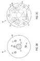
FIG. 2C is a bottom view a diode pack in accordance with an embodiment of the disclosure; -
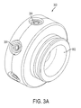
FIG. 3A is a perspective view of a connection block in accordance with an embodiment of the disclosure; -
FIG. 3B is a top view of a connection block in accordance with an embodiment of the disclosure; -
FIG. 3C is a cross sectional view of a connection block in accordance with an embodiment of the disclosure; and -
FIG. 4 is a cross sectional view of a rectifier assembly in accordance with an embodiment of the disclosure. - Referring now to
Figure 1 , agenerator 100 in accordance with an one embodiment is shown. Thegenerator 100 includes amain field stator 102 and exciter 104 both of which are disposed around arotor assembly 106. Therotor assembly 106 includes adiode pack 108 and adiode connection block 110. In one embodiment, thediode pack 108 is installed in theentire rotor assembly 106 which is configured to rotate inside of theexciter 104 andmain field stator 102. - Referring now to
FIG. 2A adiode pack 200 in accordance with one embodiment is shown. Thediode pack 200 includes anouter DC ring 202 andinner DC ring 204 which are coaxially disposed about acentral oil tube 224 and inside therotor shaft 106. In one embodiment, theouter DC ring 202 is in direct contact with the shaft for static grounding. Theouter DC ring 202 and theinner DC ring 204 are separated byspacer 212 and by aceramic resistor disk 214. Thediode pack 200 also includes acover 216 that is affixed to theouter DC ring 202 by a plurality ofbolts 220 andwashers 218. - In one embodiment, the
diode pack 200 also includes a plurality ofdiodes 206 which are disposed between theouter DC ring 202 and theinner DC ring 204. In one embodiment, thediode pack 200 includes three pairs of radially stackeddiodes 206 and adiode connection plate 226 disposed between each of the pairs of radially stackeddiodes 206. Thediode connection plates 226 are each affixed to anAC post 210. Thediode pack 200 includes one ormore DC posts 208 which are affixed to theinner DC ring 204 andouter DC ring 202. In one embodiment, thediodes 206 andplates 226 may be held in place by aspring clip 222. - Referring now to
FIG. 2B a top view of adiode pack 200 in accordance with one embodiment is shown. As illustrated thediode pack 200 includes threeAC posts 210 and twoDC posts 208 which extend from one end of thediode pack 200 in the direction of thecentral oil tube 224. - Referring now to
FIG. 2C a bottom view adiode pack 200 without thecover 216 in accordance with one embodiment is shown. As illustrated thediode pack 200 includes three pairs ofdiodes 206 which are each separated by adiode connection plate 226. Thediode pack 200 includes aninner DC ring 204 and anouter DC ring 202, which are separated by aspacer 212. - Referring now to
FIG. 3A aconnection block 300 in accordance with one embodiment is shown. Theconnection block 300 is configured to attach the end of the diode pack shown inFIG. 2B . In one embodiment, theconnection block 300 is designed to receive the AC posts and DC posts from the diode pack and to provideconnections 304 to the AC posts and DC posts. Theconnection block 300 also includes anaperture 302 configured to receive the oil tube. - Referring now to
FIG. 3B a top view of aconnection block 300 in accordance with one embodiment is shown. The end of the connection block 300 shown is configured to attach the end of the diode pack shown inFIG. 2B . In one embodiment, theconnection block 300 is designed to receive the AC posts of the diode pack inAC connectors 306 and DC posts of the diode pack inDC connectors 308. Theconnection block 300 also includes anaperture 302 configured to receive the oil tube. - Referring now to
FIG. 3C a cross sectional view of aconnection block 300 in accordance with one embodiment is shown. In one embodiment, theconnection block 300 is designed to receive the AC posts of the diode pack inAC connectors 306 and DC posts of the diode pack inDC connectors 308. Both theAC connectors 306 andDC connectors 308 include apowerband 310 configured to fittingly receive an AC post or DC post from the diode pack. Theterminals 304 also include a threaded portion, or helicoil, 312 which is configured to receive a bolt or other attachment means. - Referring now to
FIG. 4 a cross sectional view of a portion of arectifier assembly 400 in accordance with an embodiment of the disclosure is shown. Therectifier assembly 400 includes adiode pack 402 and aconnection block 404. Theconnection block 404 includes a plurality ofterminals 406 that are configured to receivebolts 408, which secure theconnection block 404 to therectifier rotor assembly 400 and provide electrical connections to thediode pack 402. Thediode pack 402 includes anouter DC ring 410 and aninner DC ring 414 and a plurality ofdiodes 412 disposed between the rings. In one embodiment, thediodes 412 are disposed in radially stacked pairs with adiode connection plate 420 disposed between each pair of diodes. One or more of thediode connections plates 420 are in electrical communication with anAC post 416. Thediode pack 402 also includes one ormore DC posts 418 that are in electrical communication with theinner DC ring 414 andouter DC ring 410. In one embodiment, theinner DC ring 414 andouter DC ring 410 are separated by aninsulator 426. Thediode pack 402 also includes acover 422 that is secured to theouter DC ring 410 via one ormore bolts 424. - In one embodiment, a diode pack is provided for a rotating rectifier assembly. The diode pack is configured to have two coaxial DC rings and radially stacked pairs of diodes disposed between the DC rings. By radially stacking diode pairs, as opposed to the traditional placement of adjacent along the rotor shaft of the rectifier assembly, the length of the diode pack can be reduced. In addition, the diode pack is configured to pass electrical signals through rotor shaft and incorporates diode package grounding similar to schemes described in patent U.S. Patent 8,063,522. In one embodiment, the configuration of the diode pack, specifically two co-axially located DC rings and three sets of radially stacked diodes, allows assembly with elimination of numerous fasteners, and reduced part count.
- While the invention has been described in detail in connection with only a limited number of embodiments, it should be readily understood that the invention is not limited to such disclosed embodiments. Rather, the invention can be modified to incorporate any number of variations, alterations, substitutions or equivalent arrangements not heretofore described, but which are commensurate with the scope of the invention. Additionally, while various embodiments of the invention have been described, it is to be understood that aspects of the invention may include only some of the described embodiments. Accordingly, the invention is not to be seen as limited by the foregoing description, but is only limited by the scope of the appended claims.
Claims (8)
- A diode pack (200;402) comprising:an inner DC ring (204;414);an outer DC ring (202;410);a plurality of diodes (206;412) disposed between the inner DC ring (204;414) and the outer DC ring (202;410), wherein the plurality of diodes (206;412) are disposed in one or more radially stacked pairs;one or more diode connection plates (226;412) disposed between each of the one or more radially stacked pair of diodes (206;412);one or more DC posts (208;418) affixed to the inner DC ring (204;414);one or more DC posts (208;418) affixed to the outer DC ring (202;414); andone or more AC posts (210;416) affixed to the one or more diode connection plates (226;420).
- The diode pack of claim 1 further comprising an insulator (212;426) disposed between the inner DC ring (204;414) and the outer DC ring (202;410).
- The diode pack of claim 1 or 2 further comprising a ceramic resistor disk (214) disposed between the inner DC ring (204) and the outer DC ring (202).
- The diode pack of any preceding claim further comprising one or more spring clips (222) disposed between the inner DC ring (204) and an inner diode (206) of the one or more radially stacked diode pairs.
- The diode pack of any preceding claim further comprising a cover (216;422) affixed to the outer DC ring (202;410) by one or more bolts (220;424).
- A rotating rectifier assembly (200;400) for a generator comprising:a diode pack (200;400) of any preceding claim; anda connection block (300;404) configured to receive the one or more DC posts (208;418) and one or more AC posts (210;416) and provide electrical connections to the diode pack (200;402).
- The rotating rectifier assembly for a generator of claim 6, wherein the connection block (300;404) includes a plurality of terminals (304;406), wherein each of the plurality of terminals (304;406) is configured to receive one of the one or more DC posts (208;418) and one or more AC posts (210;416).
- The rotating rectifier assembly for a generator of claim 7, wherein each of the plurality of terminals (304) includes a threaded portion (312) configured to receive a bolt to affix the connection block (300) to a rotating rotor shaft assembly and make electrical connections outside the shaft.
Applications Claiming Priority (1)
| Application Number | Priority Date | Filing Date | Title |
|---|---|---|---|
| US13/764,146 US20140226383A1 (en) | 2013-02-11 | 2013-02-11 | Coaxial rotating rectifier package assembly for generator |
Publications (2)
| Publication Number | Publication Date |
|---|---|
| EP2765688A2 true EP2765688A2 (en) | 2014-08-13 |
| EP2765688A3 EP2765688A3 (en) | 2018-03-28 |
Family
ID=50064484
Family Applications (1)
| Application Number | Title | Priority Date | Filing Date |
|---|---|---|---|
| EP14154185.4A Withdrawn EP2765688A3 (en) | 2013-02-11 | 2014-02-06 | Coaxial rotating rectifier package assembly for generator |
Country Status (2)
| Country | Link |
|---|---|
| US (1) | US20140226383A1 (en) |
| EP (1) | EP2765688A3 (en) |
Cited By (1)
| Publication number | Priority date | Publication date | Assignee | Title |
|---|---|---|---|---|
| EP2988400A3 (en) * | 2014-08-22 | 2016-07-06 | Hamilton Sundstrand Corporation | Grounded diode pack |
Families Citing this family (8)
| Publication number | Priority date | Publication date | Assignee | Title |
|---|---|---|---|---|
| US9843270B2 (en) | 2015-01-13 | 2017-12-12 | Hamilton Sundstrand Corporation | Phase leg arrangements for multilevel active rectifiers |
| US10879772B2 (en) * | 2019-01-08 | 2020-12-29 | Hamilton Sundstrand Corporation | Rotating resistor assemblies |
| US11245312B2 (en) * | 2019-06-28 | 2022-02-08 | Hamilton Sundstrand Corporation | High speed generator connection assembly |
| US11631325B2 (en) * | 2019-08-26 | 2023-04-18 | GM Global Technology Operations LLC | Methods and systems for traffic light state monitoring and traffic light to lane assignment |
| US11764648B2 (en) | 2020-12-07 | 2023-09-19 | Hamilton Sundstrand Corporation | Rotating rectifiers |
| US11799391B2 (en) | 2021-03-13 | 2023-10-24 | Hamilton Sundstrand Corporation | Diode mounting ring with contact band inserts |
| US12009126B2 (en) | 2021-03-13 | 2024-06-11 | Hamilton Sundstrand Corporation | Resistor support assembly with spring seat |
| US11949294B2 (en) * | 2021-03-13 | 2024-04-02 | Hamilton Sundstrand Corporation | Resistor plate assembly with contact bands |
Citations (1)
| Publication number | Priority date | Publication date | Assignee | Title |
|---|---|---|---|---|
| US8063522B2 (en) | 2009-09-14 | 2011-11-22 | Hamilton Sundstrand Corporation | Generator rotor ground bushing |
Family Cites Families (10)
| Publication number | Priority date | Publication date | Assignee | Title |
|---|---|---|---|---|
| DE8717864U1 (en) * | 1987-09-16 | 1990-11-29 | Arthur Eugster AG, Romanshorn | Device for preparing hot drinks |
| US4806814A (en) * | 1987-11-16 | 1989-02-21 | Sundstrand Corporation | Half-wave rotary rectifier assembly |
| US5587616A (en) * | 1993-05-04 | 1996-12-24 | Sundstrand Corporation | Rotor for a dynamoelectric machine having a one-piece rotation rectifier |
| US5773903A (en) * | 1996-12-20 | 1998-06-30 | Sundstrand Corporation | Rotating rectifier assembly |
| US7253167B2 (en) * | 2004-06-30 | 2007-08-07 | Bristol-Myers Squibb Company | Tricyclic-heteroaryl compounds useful as kinase inhibitors |
| JP4550673B2 (en) * | 2005-06-17 | 2010-09-22 | 本田技研工業株式会社 | Vehicle subframe |
| US7511392B2 (en) * | 2005-06-17 | 2009-03-31 | Hamilton Sundstrand Corporation | Rotating rectifier module |
| US7586224B2 (en) * | 2005-11-16 | 2009-09-08 | Hamilton Sundstrand Corporation | Rotating rectifier assembly |
| JP4600373B2 (en) * | 2006-09-12 | 2010-12-15 | 株式会社デンソー | Vehicle alternator |
| US7868494B2 (en) * | 2008-08-26 | 2011-01-11 | Hamilton Sundstrand Corporation | Rectifier assembly |
-
2013
- 2013-02-11 US US13/764,146 patent/US20140226383A1/en not_active Abandoned
-
2014
- 2014-02-06 EP EP14154185.4A patent/EP2765688A3/en not_active Withdrawn
Patent Citations (1)
| Publication number | Priority date | Publication date | Assignee | Title |
|---|---|---|---|---|
| US8063522B2 (en) | 2009-09-14 | 2011-11-22 | Hamilton Sundstrand Corporation | Generator rotor ground bushing |
Cited By (1)
| Publication number | Priority date | Publication date | Assignee | Title |
|---|---|---|---|---|
| EP2988400A3 (en) * | 2014-08-22 | 2016-07-06 | Hamilton Sundstrand Corporation | Grounded diode pack |
Also Published As
| Publication number | Publication date |
|---|---|
| EP2765688A3 (en) | 2018-03-28 |
| US20140226383A1 (en) | 2014-08-14 |
Similar Documents
| Publication | Publication Date | Title |
|---|---|---|
| US20140226383A1 (en) | Coaxial rotating rectifier package assembly for generator | |
| US8063522B2 (en) | Generator rotor ground bushing | |
| US7511392B2 (en) | Rotating rectifier module | |
| US9035508B2 (en) | Rotating resistor assembly | |
| US10516321B2 (en) | AC power generator | |
| CN104009649B (en) | rotating rectifier assembly for motor | |
| US3160771A (en) | Semiconductor rectifier device for electric machines | |
| US10381892B2 (en) | Stator assembly, motor having the same and method of manufacturing the same | |
| US9472996B2 (en) | Terminal assembly | |
| US9035507B2 (en) | Electric machine and rectifier assembly therefor | |
| KR20110048661A (en) | Fan motor for controller type with bus bar winding structure stator | |
| US9490674B2 (en) | Rotating rectifier assembly for electric machine | |
| US6859019B2 (en) | System and method for coupling rectifiers of an exciter to the rotor of a main generator | |
| CN111919363A (en) | Combinations of AC motors and converter units and wind power plants | |
| US20150123507A1 (en) | Electric Generator for Wind Power Installation | |
| WO2017098212A3 (en) | Wind turbine apparatuses | |
| US9124166B2 (en) | Electric motor | |
| JP2017034741A (en) | Rectifier and rotating electric machine | |
| EP2793373A2 (en) | Terminal block cover | |
| CN104600935B (en) | Generator | |
| KR102254356B1 (en) | BUSBAR assembly and Motor having the same | |
| EP3866314B1 (en) | Rotating rectifier assemblies, generators having rotating rectifier assemblies, and methods of making rotating rectifier assemblies | |
| CN104377893B (en) | Motor and the method for manufacturing motor | |
| US7508107B2 (en) | High current rotating exciter | |
| CN113489346A (en) | Rotary rectifier suitable for high-speed heavy current |
Legal Events
| Date | Code | Title | Description |
|---|---|---|---|
| PUAI | Public reference made under article 153(3) epc to a published international application that has entered the european phase |
Free format text: ORIGINAL CODE: 0009012 |
|
| 17P | Request for examination filed |
Effective date: 20140206 |
|
| AK | Designated contracting states |
Kind code of ref document: A2 Designated state(s): AL AT BE BG CH CY CZ DE DK EE ES FI FR GB GR HR HU IE IS IT LI LT LU LV MC MK MT NL NO PL PT RO RS SE SI SK SM TR |
|
| AX | Request for extension of the european patent |
Extension state: BA ME |
|
| PUAL | Search report despatched |
Free format text: ORIGINAL CODE: 0009013 |
|
| AK | Designated contracting states |
Kind code of ref document: A3 Designated state(s): AL AT BE BG CH CY CZ DE DK EE ES FI FR GB GR HR HU IE IS IT LI LT LU LV MC MK MT NL NO PL PT RO RS SE SI SK SM TR |
|
| AX | Request for extension of the european patent |
Extension state: BA ME |
|
| RIC1 | Information provided on ipc code assigned before grant |
Ipc: H02M 7/00 20060101ALI20180217BHEP Ipc: H02M 7/06 20060101ALI20180217BHEP Ipc: H02K 11/04 20160101AFI20180217BHEP |
|
| STAA | Information on the status of an ep patent application or granted ep patent |
Free format text: STATUS: REQUEST FOR EXAMINATION WAS MADE |
|
| STAA | Information on the status of an ep patent application or granted ep patent |
Free format text: STATUS: THE APPLICATION IS DEEMED TO BE WITHDRAWN |
|
| 18D | Application deemed to be withdrawn |
Effective date: 20180929 |