EP2765405A1 - Nephelometry system - Google Patents
Nephelometry system Download PDFInfo
- Publication number
- EP2765405A1 EP2765405A1 EP13154767.1A EP13154767A EP2765405A1 EP 2765405 A1 EP2765405 A1 EP 2765405A1 EP 13154767 A EP13154767 A EP 13154767A EP 2765405 A1 EP2765405 A1 EP 2765405A1
- Authority
- EP
- European Patent Office
- Prior art keywords
- light
- lichtumlenkvorrichtung
- photodetector
- light beam
- measuring cell
- Prior art date
- Legal status (The legal status is an assumption and is not a legal conclusion. Google has not performed a legal analysis and makes no representation as to the accuracy of the status listed.)
- Withdrawn
Links
Images

Classifications
-
- G—PHYSICS
- G01—MEASURING; TESTING
- G01N—INVESTIGATING OR ANALYSING MATERIALS BY DETERMINING THEIR CHEMICAL OR PHYSICAL PROPERTIES
- G01N21/00—Investigating or analysing materials by the use of optical means, i.e. using sub-millimetre waves, infrared, visible or ultraviolet light
- G01N21/17—Systems in which incident light is modified in accordance with the properties of the material investigated
- G01N21/47—Scattering, i.e. diffuse reflection
- G01N21/49—Scattering, i.e. diffuse reflection within a body or fluid
- G01N21/51—Scattering, i.e. diffuse reflection within a body or fluid inside a container, e.g. in an ampoule
-
- G—PHYSICS
- G01—MEASURING; TESTING
- G01N—INVESTIGATING OR ANALYSING MATERIALS BY DETERMINING THEIR CHEMICAL OR PHYSICAL PROPERTIES
- G01N21/00—Investigating or analysing materials by the use of optical means, i.e. using sub-millimetre waves, infrared, visible or ultraviolet light
- G01N21/17—Systems in which incident light is modified in accordance with the properties of the material investigated
- G01N21/47—Scattering, i.e. diffuse reflection
- G01N2021/4704—Angular selective
- G01N2021/4707—Forward scatter; Low angle scatter
-
- G—PHYSICS
- G01—MEASURING; TESTING
- G01N—INVESTIGATING OR ANALYSING MATERIALS BY DETERMINING THEIR CHEMICAL OR PHYSICAL PROPERTIES
- G01N2201/00—Features of devices classified in G01N21/00
- G01N2201/06—Illumination; Optics
- G01N2201/064—Stray light conditioning
Definitions
- the invention relates to a nephelometry system suitable for an analyzer with a light source, a recording position for a measuring cell and a photodetector, which are arranged such that a light beam emanating from the light source strikes the photodetector through the measuring cell via a light deflecting device.
- Today's analyzers are capable of performing a variety of detection reactions and analyzes on a sample.
- various devices for the spatial transfer of measuring cells, reaction vessels and reagent containers are required, such.
- transfer arms with gripping function conveyor belts or rotatable transport wheels, as well as for the transfer of liquids, such.
- the device includes a control unit, which is capable of using the appropriate software to plan the work steps for the desired analysis largely independent and work off.
- optical methods enable the qualitative and quantitative detection of analytes, ie the one or more substances to be detected or determined, in samples.
- the determination of clinically relevant parameters, such as the concentration or activity of an analyte is often done by mixing a portion of a sample with one or more test reagents in a reaction vessel, which may also be the measurement cell, thereby initiating, for example, a biochemical reaction or a specific binding reaction involving a measurable change in an optical or other physical Property of the test batch causes.
- nephelometric system By means of nephelometry, the concentration of finely divided, colloidal particles in liquids or gases can be determined quantitatively: If a suspension of small particles is introduced into a light beam, part of the light that has entered is absorbed; another part, also called a primary jet, leaves the suspension unscattered and again another part is scattered sideways to the incoming beam. In nephelometry, this laterally emerging scattered light is measured.
- Nephelometry is used above all for the quantitative or qualitative detection of analytes, for example proteins, which can preferably be detected by means of a specific binding reaction between two specific binding partners, for example by means of antigen-antibody binding.
- Quantitative detection measures the amount, concentration or activity of the analyte in the sample.
- the term "quantitative detection” also includes semiquantitative methods which can only capture the approximate amount, concentration or activity of the analyte in the sample or can only serve for a relative indication of quantity, concentration or activity.
- qualitative detection is meant detecting the presence of the analyte in the sample at all, or indicating that the amount, concentration or activity of the analyte in the sample is below or above a certain threshold (s).
- a “specific binding partner” is meant a member of a specific binding pair.
- the members of a specific binding pair are two molecules, each having at least one complementary to a structure of the other molecule structure, wherein the two molecules are able to bind specifically via a bond of the complementary structures.
- the term molecule also includes molecular complexes such as e.g. Enzymes consisting of apo- and coenzyme, proteins consisting of several subunits, lipoproteins consisting of protein and lipids, etc.
- Specific binding partners may be naturally occurring but also e.g. be produced by chemical synthesis, microbiological techniques and / or genetic engineering substances. To illustrate the term specific binding partner, but not to be construed as limiting, e.g.
- Specific binding pairs Examples of these are: antibody antigen, antibody hapten, operator repressor, nuclease nucleotide, biotin avidin, lectin polysaccharide, stearide-boride protein, active substance receptor, hormone receptor, enzyme substrate, IgG protein A, complementary oligo- or polynucleotides, etc.
- a nephelometric system usually comprises at least one light source and at least one photodetector and at least one receiving position for a measuring cell.
- the photodetector may be disposed laterally of the light beam emitted from the light source to detect the scattered light at an angle of 90 ° to the direction of the light beam emitted from the light source.
- the intensity of the scattered light which is scattered in angular ranges by 90 ° to the direction of the light beam emitted from the light source may be relatively low, and the influence of the measurement by the non-scattered part of the light beam emitted by the light source, called the primary beam relatively low.
- the light source, receiving position and photodetector may be arranged such that the photodetector detects the scattered light at angles or angular ranges about the propagation direction of the light beam emitted from the light source in which the intensity of the scattered light may be relatively high.
- the photodetector reaches not only the stray light but also the primary beam.
- optical apertures have been used so far. These are by means of thin fasteners such.
- EP 0 997 726 A2 describes a nephelometric in-process optical control detection unit which enables the separate detection of the scattered light and the primary beam.
- the separation of the primary beam from the scattered light takes place by the primary beam on a specially shaped Aperture, or a specially constructed mirror or lens with a portion for receiving a beam guiding or - deflecting unit, wherein the aperture, the mirror or the lens is inserted into the beam path.
- the scattered part of the light does not strike the aperture, the mirror or the lens. This continuous portion of the light is detected behind the plane of the diaphragm, mirror or lens.
- the disadvantage here can be that such diaphragms, mirrors or lenses are usually comparatively filigree and mechanically sensitive.
- the fastening devices that protrude from the side into the light beam, namely, must be particularly thin so as not to hide stray light. Nevertheless, it is inevitable in such a structure that a part of the fastening devices hides the stray light and thus the measurement is potentially disturbed.
- optical property is to be understood, for example, as the reflectivity or absorption capacity of an optical element.
- the measuring cell may be e.g. to handle a cuvette, which is often made of glass, plastic or quartz glass. Also flow cuvettes can be used in the nephelometry system according to the invention as a measuring cell.
- a "light deflection apparatus” is to be understood, for example, as an optical element which changes the propagation direction of light beams by specular reflection or total reflection of the light beams at at least one boundary surface.
- specular reflection or total reflection at an interface light rays are reflected such that the angle of the incident light beam relative to the interface normal (angle of incidence) is equal to the angle of the emergent light beam relative to the interface normal (angle of reflection), and that of the incident light beam, the interface normal and the emergent Light beam lie in a plane.
- a light deflection device may for example consist of a mirror or a reflection prism.
- the forwarding of the light to the photodetector can also be targeted via one or more light guides.
- a light deflection device according to the invention can also consist directly of a light guide.
- the invention is based on the consideration that an improved measurement quality can be achieved in particular could, if the directed onto the photodetector primary beam could be selectively hidden, without holding devices of a diaphragm hide parts of the scattered light to be measured.
- This can be achieved by completely or largely dispensing with diaphragms arranged in the light beam and, instead, deflecting the light beam by means of a light deflection device, wherein scattered parts of the light beam are directed into the photodetector.
- the light deflection can be used in the manner of a double use on the one hand for the suppression or partial suppression of the primary beam, on the other hand, but it can also allow the deflection of the light beam a more compact design of the nephelometry system.
- Non-scattered and scattered in the forward direction portions of the light beam can be, for example, also completely or partially time-delayed directed to the photodetector on which the scattered parts of the light beam are directed and / or at least one other photodetector.
- the advantages achieved by the invention are, in particular, that by deflecting only desired portions of the light beam in the photodetector, e.g.
- By means of targeted areawise manipulation of the reflection properties and / or transmission properties of the light deflection device used for the deflection a particularly simple, easily modifiable and structurally stable construction of a nephelometric system becomes possible.
- Previously required central apertures in the light beam with corresponding filigree fixtures can be omitted. This also results in considerable cost advantages.
- the latter separates at least one first light beam component, which consists of a first partial region of the cross-sectional surface of the light beam and which strikes the first partial region (30, 30 ', 30 ") of the light deflection device, spatially from a second light beam component from a second section of the Cross-sectional area of the light beam is and which on a second portion (34, 34 ') of the light deflection device meets.
- non-scattered portions of the light beam and forwardly scattered portions of the light beam may be spatially separated from scattered portions of the light beam that are outside the cross-sectional area of the primary beam in the plane of the light-deflecting device by exposing the light from the cross-sectional area of the primary beam to a first portion (30) meets the light deflection device, which has a changed, for example reduced or increased, transmissivity and / or altered, for example reduced or increased, reflectivity.
- portions of the light beam can be spatially separated, which are scattered in the plane of the light deflection device in different areas of the cross-sectional area of the light beam outside the primary beam.
- the diversity of the partial regions in at least one optical property can be achieved, for example, by changing the optical property in at least the first partial region (30, 30 ', 30' ') and / or the second partial region (34, 34'). This can e.g. by changing the reflection properties and / or the transmission properties of the light deflection device in at least the first partial area (30, 30 ', 30' ') and / or the second partial area (34, 34').
- the relevant subarea of the light deflection device could be completely or partially, for example only the specular interface, removed. This can be done for example by drilling, punching, erosion, or other physical or chemical methods.
- the subregion could be covered by a light-absorbing and / or light-reflecting lacquer or another light-absorbing and / or light-reflecting material.
- the subarea is covered with a light-absorbing and / or light-reflecting foil.
- a film can be cut particularly easily and thus brought into the desired shape.
- the film is light-absorbing. As a result, reflection and / or transmission of unwanted regions of the light beam into the photodetector is effectively prevented.
- the film is not perpendicular, d. H. obliquely incident light absorbs light, since, for example, the light does not strike the light deflecting device perpendicularly when the light beam is deflected.
- appropriate films are to be selected, which have a good light absorption at oblique incidence of light.
- the spatial separation of the light beam parts could, for example, also be achieved by at least one change in the reflection properties in at least one subregion of the at least one boundary surface of the reflection prism at which total reflection takes place.
- a change in the reflection properties of a subregion of an interface on the total reflection can be achieved by applying a material with the same or similar refractive index to the reflection prism as the material from which the reflection prism is made in a subregion of the at least one boundary surface on which total reflection takes place . is added and thereby the interface on which total reflection takes place, is removed in a sub-area and thus no total reflection occurs in this sub-area.
- the light that falls on this subarea can be forwarded in the attached material, and / or derived.
- the transmission and / or dissipation of the light in this sub-region is effected by at least one light guide.
- the spatial separation of the light beam parts by changing the transmission properties, and / or the reflection properties of the surface of the reflection prism, through which the light beam coupled into the at least one reflection prism and / or coupled can be achieved.
- the partial area of the surface can be provided with a light-absorbing and / or light-reflecting lacquer, and / or covered with a light-absorbing and / or light-reflecting foil, and / or another light-absorbing and / or light-reflecting material, and / or a mirror be.
- the spatial separation of the light beam parts could be achieved, for example, by changing the transmission properties and / or the reflection properties of the surface of the optical waveguide through which the light beam is coupled into the at least one optical waveguide and / or decoupled.
- the partial area of the surface may be provided with a light-absorbing and / or light-reflecting lacquer, and / or with a light-absorbing and / or light-reflecting foil, and / or with a mirror.
- the deflection by the inventive light deflection device (14) by an angle of 20 ° to 180 °, preferably 60 ° to 120 °, particularly preferably 80 ° to 100 °, very particularly preferably 85 ° to 95 °, very particularly preferably 90 °, to the propagation direction of the center of the light beam after passing through the measuring cell (8 ).
- the first subregion (30, 30 ', 30' '), in which the reflection properties and / or the transmission properties are different from the second subregion (34, 34'), is arranged such that the center of the light beam cross section meets this first portion. Since the scattering typically takes place in all spatial directions, a rotationally symmetrical pattern results in the light beam cross section around the primary beam.
- the primary beam is for example in the center of the light beam cross-section.
- the entire primary beam or almost the entire primary beam impinges on the first partial region (30) of the light deflection device.
- the first subregion (30 ', 30 ") is arranged in such a way that parts of the light ray which lie outside a predetermined minimum distance from the center of the light beam strike the first subregion (30', 30").
- the light-deflecting region of the Lichtumlenkvorraum be limited to the outside, which z. B. with regard to the absolute normalization of the nephelometry system may be advantageous because always only a predetermined range around the primary beam around is used for the measurement and thus the measured cross-sectional area is normalized.
- the second subregion (34, 34 ') can be arranged such that light scattered in certain angular ranges can be separated from one another. This is advantageous, for example, because light scattered in certain angular ranges, for example, informs about certain Length scales and shapes of the scattering objects in the sample transmitted.
- the light beam impinges on the Lichtumlenkvoriques at an oblique angle, such. B. at an angle of 45 ° at a deflection by 90 ° in the case of deflection by a mirror, due to the inclination, for example, an elliptical shape of the portion necessary to hide a circular cross-section of the light beam.
- the light source comprises at least one laser, and / or at least one light-emitting diode (LED), and / or at least one incandescent lamp, and / or at least one gas discharge lamp.
- LED light-emitting diode
- the light source comprises at least one laser diode.
- a coherent and collimated light beam can be generated in a particularly simple manner, which has particularly advantageous properties for nephelometry.
- the light beam has a low divergence and therefore experiences comparatively little widening over the running distance.
- the primary beam and scattered light in the photodetector can be distinguished from one another particularly well. This also applies after scattering, bundling or deflection of the light beam by means of lenses and mirrors.
- the use of at least one laser diode as the light source makes it possible, in a particularly simple embodiment, to arrange the first subarea (30) in such a way that the entire primary beam of the laser diode strikes the first subarea (30). As a result, only scattered light is picked up by the photodetector and used for the measurement.
- the light source emits light in light wavelength ranges between 200 nm and 1400 nm. In a preferred embodiment, the light source emits light in light wavelength ranges between 300 and 1100 nm.
- Another object of the invention is an analysis device which comprises an aforementioned nephelometry system according to the invention.
- the invention also includes methods for determining the concentration, amount and / or activity of at least one analyte in a sample, characterized in that the concentration, amount and / or activity of the analyte is determined with one of the aforementioned nephelometry systems according to the invention.
- sample is to be understood as meaning the material that presumably contains the substance to be detected (the analyte).
- the term sample in particular comprises biological fluids of humans or animals such as e.g. Blood, plasma, serum, sputum, exudate, bronchoalveolar lavage, lymphatic fluid, synovial fluid, seminal fluid, vaginal mucus, feces, urine, cerebrospinal fluid, but also e.g. Tissue or cell culture samples prepared by homogenization or cell lysis for the nephelometric determination.
- biological fluids of humans or animals such as e.g. Blood, plasma, serum, sputum, exudate, bronchoalveolar lavage, lymphatic fluid, synovial fluid, seminal fluid, vaginal mucus, feces, urine, cerebrospinal fluid, but also e.g. Tissue or cell culture samples prepared by homogenization or cell lysis for the nephelometric determination.
- the nephelometry system (1) according to FIG. 1 is embedded in a not-shown analyzer, which is designed to perform a variety of analyzes of samples.
- the automatic analyzer comprises a plurality of transport devices, not shown, as well as a control unit for the automated analysis of the analyzes.
- the nephelometry system (1) comprises a receiving position (4) for a measuring cell (2). It further comprises a photodetector (6) capable of accurately measuring the amount of light incident on a given surface and a light source (8) comprising a laser diode (10) and an upstream lens (12). The light source (8) thus emits a light beam of coherent and collimated laser light. This is directed in the direction A indicated by an arrow and strikes the measuring cell (2) in the receiving position (4).
- a mirror In a straight line from the light source (8) via the receiving position (4) in the direction A, a mirror is arranged as Lichtumlenkvoriques (14) whose surface is inclined by 45 ° relative to the direction A.
- the direction B In a straight line starting from the mirror as the light deflection device (14), in the direction B, which is again indicated by an arrow, two lenses (16, 18) which are designed as converging lenses are incorporated Filter (20) and finally the photodetector (6) arranged.
- the filter (20) prevents vertical reflection.
- the direction B is angled 90 ° with respect to the direction A.
- the photodetector (6) is connected to the aforementioned control unit and allows an evaluation of the scattering of the laser beam emitted by the light source (8). All components described are housed in a housing (22).
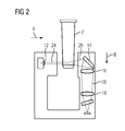
- FIG. 2 To clarify the beam path of the laser beam is this in FIG. 2 shown. In this case, only the optically relevant parts measuring cell (2), lens (12), mirror as Lichtumlenkvoriques (14) and lenses (16, 18) are explicitly shown. The remaining components are shown only in the manner of a silhouette.
- the light from the lens (12) is collimated into a collimated laser beam which neither narrows nor widens in a first portion (24). This laser beam strikes the measuring cell (2) at the end of the first section (24).
- the laser beam is scattered, so that only a part unscratched leaves the measuring cell (2) in the second section (26). This part is the primary beam. Another part of the light is scattered, which in the second section (26) leads to an expansion of the light beam. In the second section, the light impinges on the mirror as light deflection device (14), which deflects it in direction B, so that it strikes the lens (16).
- the light finally strikes the lenses (16, 18), is thereby focused and finally into guided the photodetector (6), where the strength of the scattered light is determined.
- the light intensity of the scattered light will be much lower than that of the still entering the photodetector (6) primary beam.
- the mirror is provided as Lichtumlenkvoriques (14), for example with a film which reduces the reflectivity.
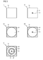
- Lichtumlenkvoriques (14) is in each case from the direction of A from FIG. 1 . 2 shown.
- the first portion (30, 30 ', 30' ') is arranged on the mirror, that the primary beam is hidden.
- the first portion (30) appears circular from the direction of view A in the projection and is circular about the center, i. H. centers the center of the primary beam incident on the mirror (II, IV, V).
- the first portion (30 ') begins concentrically with the first portion (30) at a distance and extends to the outer edge of the mirror (III, IV, V).
- the first portion (30 '') is disposed between the first portion (30) and (30 ') (V) to be e.g. Measure light scattered in certain angular ranges separately from each other.
- a region of the mirror delimited by concentric circles remains in the projection as a light deflection device (14) with a reflective surface Surface left over.
- the remaining reflecting surface appears to be an area bounded by concentric ellipses. This area offers a clearly normalized surface, within which stray light is transmitted, thus improving the measurement result on the one hand in terms of the signal-to-noise ratio, and on the other hand also in terms of normalizability.
- the circular shapes described arise only when viewed from the viewing direction A.
- elliptical shapes are obtained here.
- the actually collaboratestede form of the films thus results from the requirement that from the direction of the light source, the said circular shape should be visible and thus depends on the inclination of the mirror as Lichtumlenkvortechnisch (14) relative to the emission direction of the light source (8).
- the film in the first subregion (30, 30 ', 30 ") itself is designed such that it does not reflect light, and in particular obliquely incident light, and is light-absorptive.
- the reflection properties could also be changed otherwise, for example by painting the surface, removing parts of the mirror, for example by drilling, punching, removing or removing the mirror surface on the back.
Abstract
Description
Die Erfindung betrifft ein für ein Analysegerät geeignetes Nephelometriesystem mit einer Lichtquelle, einer Aufnahmeposition für eine Messzelle und einem Fotodetektor, die derart angeordnet sind, dass ein von der Lichtquelle ausgehender Lichtstrahl durch die Messzelle über eine Lichtumlenkvorrichtung auf den Fotodetektor trifft.The invention relates to a nephelometry system suitable for an analyzer with a light source, a recording position for a measuring cell and a photodetector, which are arranged such that a light beam emanating from the light source strikes the photodetector through the measuring cell via a light deflecting device.
Zahlreiche Nachweis- und Analyseverfahren zur Bestimmung physiologischer Parameter in Körperflüssigkeitsproben oder anderen biologischen Proben werden heute automatisiert in großer Anzahl in automatischen Analysegeräten, auch so genannten in vitro-Diagnostiksystemen, durchgeführt.Numerous detection and analysis methods for the determination of physiological parameters in body fluid samples or other biological samples are now carried out automatically in large numbers in automatic analyzers, also known as in vitro diagnostic systems.
Heutige Analysegeräte sind in der Lage, eine Vielzahl von Nachweisreaktionen und Analysen mit einer Probe durchzuführen. Um eine Vielzahl von Untersuchungen automatisiert durchführen zu können, sind diverse Vorrichtungen zum räumlichen Transfer von Messzellen, Reaktionsbehältern und Reagenzbehältern erforderlich, wie z. B. Transferarme mit Greiffunktion, Transportbänder oder drehbare Transporträder, sowie zum Transfer von Flüssigkeiten, wie z. B. Pipettiervorrichtungen. Das Gerät umfasst eine Steuereinheit, die mittels entsprechender Software dazu in der Lage ist, die Arbeitsschritte für die gewünschten Analysen weitgehend selbstständig zu planen und abzuarbeiten.Today's analyzers are capable of performing a variety of detection reactions and analyzes on a sample. In order to perform a variety of studies automated, various devices for the spatial transfer of measuring cells, reaction vessels and reagent containers are required, such. As transfer arms with gripping function, conveyor belts or rotatable transport wheels, as well as for the transfer of liquids, such. B. pipetting devices. The device includes a control unit, which is capable of using the appropriate software to plan the work steps for the desired analysis largely independent and work off.
Viele der in derartigen automatisiert arbeitenden Analysegeräten verwendeten Analyseverfahren beruhen auf optischen Methoden. Diese Verfahren ermöglichen den qualitativen und quantitativen Nachweis von Analyten, d.h. der oder die nachzuweisenden oder zu bestimmenden Substanzen, in Proben. Die Bestimmung klinisch relevanter Parameter, wie zum Beispiel der Konzentration oder Aktivität eines Analyten, erfolgt vielfach, indem ein Teil einer Probe mit einem oder mehreren Testreagenzien in einem Reaktionsgefäß, welches auch die Messzelle sein kann, vermischt wird, wodurch z.B. eine biochemische Reaktion oder eine spezifische Bindungsreaktion in Gang gesetzt wird, die eine messbare Veränderung einer optischen oder anderen physikalischen Eigenschaft des Testansatzes bewirkt.Many of the analysis methods used in such automated analyzers rely on optical methods. These methods enable the qualitative and quantitative detection of analytes, ie the one or more substances to be detected or determined, in samples. The determination of clinically relevant parameters, such as the concentration or activity of an analyte, is often done by mixing a portion of a sample with one or more test reagents in a reaction vessel, which may also be the measurement cell, thereby initiating, for example, a biochemical reaction or a specific binding reaction involving a measurable change in an optical or other physical Property of the test batch causes.
Insbesondere können moderne Analysegeräte mit einem Nephelometriesystem ausgestattet sein. Mittels der Nephelometrie lässt sich die Konzentration feinverteilter, kolloidaler Teilchen in Flüssigkeiten oder Gasen quantitativ bestimmen: Wird eine Suspension kleiner Partikel in einen Lichtstrahl verbracht, so wird ein Teil des eingetretenen Lichtes absorbiert, ein anderer Teil, auch als Primärstrahl bezeichnet, verlässt die Suspension ungestreut und wieder ein anderer Teil wird seitlich zum eintretenden Strahl gestreut. Bei der Nephelometrie wird dieses seitlich austretende Streulicht gemessen.In particular, modern analyzers can be equipped with a nephelometric system. By means of nephelometry, the concentration of finely divided, colloidal particles in liquids or gases can be determined quantitatively: If a suspension of small particles is introduced into a light beam, part of the light that has entered is absorbed; another part, also called a primary jet, leaves the suspension unscattered and again another part is scattered sideways to the incoming beam. In nephelometry, this laterally emerging scattered light is measured.
Die Nephelometrie wird vor allem für den quantitativen oder qualitativen Nachweis von Analyten, beispielsweise Proteinen, eingesetzt, die sich bevorzugt mittels einer spezifische Bindungsreaktion zwischen zwei spezifischen Bindungspartnern, z.B. mittels Antigen-Antikörper-Bindung, nachweisen lassen. Bei einem quantitativen Nachweis wird die Menge, die Konzentration oder die Aktivität des Analyten in der Probe gemessen. Von dem Begriff des "quantitativen Nachweises" sind auch semiquantitative Methoden umfasst, die nur die ungefähre Menge, Konzentration oder Aktivität des Analyten in der Probe erfassen oder nur zu einer relativen Mengen-, Konzentrations- oder Aktivitätsangabe dienen können. Unter einem qualitativen Nachweis ist der Nachweis des Vorhandenseins des Analyten in der Probe überhaupt oder das Anzeigen, dass die Menge, Konzentration oder Aktivität des Analyten in der Probe unterhalb oder oberhalb eines bestimmten oder mehrerer bestimmter Schwellenwerte liegt, zu verstehen.Nephelometry is used above all for the quantitative or qualitative detection of analytes, for example proteins, which can preferably be detected by means of a specific binding reaction between two specific binding partners, for example by means of antigen-antibody binding. Quantitative detection measures the amount, concentration or activity of the analyte in the sample. The term "quantitative detection" also includes semiquantitative methods which can only capture the approximate amount, concentration or activity of the analyte in the sample or can only serve for a relative indication of quantity, concentration or activity. By qualitative detection is meant detecting the presence of the analyte in the sample at all, or indicating that the amount, concentration or activity of the analyte in the sample is below or above a certain threshold (s).
Unter einem "spezifischen Bindungspartner" ist ein Mitglied eines spezifischen Bindungspaars zu verstehen. Bei den Mitgliedern eines spezifischen Bindungspaars handelt es sich um zwei Moleküle, die jeweils mindestens eine zu einer Struktur des anderen Moleküls komplementäre Struktur aufweisen, wobei die beiden Moleküle sich über eine Bindung der komplementären Strukturen spezifisch zu binden vermögen. Von dem Begriff Molekül sind auch Molekülkomplexe umfasst wie z.B. Enzyme, die aus Apo- und Coenzym bestehen, Proteine, die aus mehreren Untereinheiten bestehen, Lipoproteine bestehend aus Protein und Lipiden, etc. Spezifische Bindungspartner können natürlich vorkommende aber auch z.B. mittels chemischer Synthese, mikrobiologischer Techniken und/oder gentechnischer Verfahren hergestellte Substanzen sein. Zur Illustration des Begriffs spezifischer Bindungspartner, aber nicht als Einschränkung zu verstehend, sind z.B. zu nennen: Thyroxinbindendes Globulin, steoridbindende Proteine, Antikörper, Antigene, Haptene, Enzyme, Lektine, Nukleinsäuren, Repressoren, Oligo- und Polynukleotide, Protein A, Protein G, Avidin, Streptavidin, Biotin, Komplementkomponente C1q, nukleinsäurebindende Proteine, etc. Spezifische Bindungspaare sind beispielsweise: Antikörper-Antigen, Antikörper-Hapten, Operator-Repressor, Nuclease-Nukleotid, Biotin-Avidin, Lektin-Polysaccharid, Steoridsteoridbindendes Protein, Wirkstoff-Wirkstoffrezeptor, Hormon-Hormonrezeptor, Enzym-Substrat, IgG-Protein A, komplementäre Oligo- oder Polynukleotide, etc.By a "specific binding partner" is meant a member of a specific binding pair. The members of a specific binding pair are two molecules, each having at least one complementary to a structure of the other molecule structure, wherein the two molecules are able to bind specifically via a bond of the complementary structures. The term molecule also includes molecular complexes such as e.g. Enzymes consisting of apo- and coenzyme, proteins consisting of several subunits, lipoproteins consisting of protein and lipids, etc. Specific binding partners may be naturally occurring but also e.g. be produced by chemical synthesis, microbiological techniques and / or genetic engineering substances. To illustrate the term specific binding partner, but not to be construed as limiting, e.g. Thyroxin-binding globulin, steroids-binding proteins, antibodies, antigens, haptens, enzymes, lectins, nucleic acids, repressors, oligo- and polynucleotides, protein A, protein G, avidin, streptavidin, biotin, complement component C1q, nucleic acid-binding proteins, etc. Specific binding pairs Examples of these are: antibody antigen, antibody hapten, operator repressor, nuclease nucleotide, biotin avidin, lectin polysaccharide, stearide-boride protein, active substance receptor, hormone receptor, enzyme substrate, IgG protein A, complementary oligo- or polynucleotides, etc.
Ein Nephelometriesystem umfasst üblicherweise mindestens eine Lichtquelle und mindestens einen Fotodetektor sowie mindestens eine Aufnahmeposition für eine Messzelle.A nephelometric system usually comprises at least one light source and at least one photodetector and at least one receiving position for a measuring cell.
Auf dem Markt existieren unterschiedliche Bauweisen, die sich in der Anordnung von Lichtquelle, Aufnahmeposition für die Messzelle und Fotodetektor unterscheiden. Siehe hierzu auch z.B.
Hierfür wurden bislang optische Blenden eingesetzt. Diese werden mittels dünner Befestigungen wie z. B. Drähten im Strahlengang gehalten und hinsichtlich ihrer Größe und Form so angepasst, dass sie einen möglichst großen Teil des Primärstrahls ausblenden, so dass möglichst ausschließlich Streulicht auf den Detektor trifft.For this purpose, optical apertures have been used so far. These are by means of thin fasteners such. B. wires held in the beam path and adjusted in size and shape so that they hide as much of the primary beam, so that as far as possible only stray light hits the detector.
Nachteilig kann hierbei jedoch sein, dass derartige Blenden, Spiegel oder Linsen üblicherweise vergleichsweise filigran und mechanisch empfindlich sind. Gerade die Befestigungsvorrichtungen, die von der Seite in den Lichtstrahl ragen, müssen nämlich besonders dünn sein, um kein Streulicht auszublenden. Dennoch ist es bei einem derartigen Aufbau unvermeidlich, dass ein Teil der Befestigungsvorrichtungen das Streulicht ausblendet und somit die Messung potentiell gestört wird.However, the disadvantage here can be that such diaphragms, mirrors or lenses are usually comparatively filigree and mechanically sensitive. In particular, the fastening devices that protrude from the side into the light beam, namely, must be particularly thin so as not to hide stray light. Nevertheless, it is inevitable in such a structure that a part of the fastening devices hides the stray light and thus the measurement is potentially disturbed.
Es ist daher Aufgabe der Erfindung, ein Nephelometriesystem der eingangs genannten Art, insbesondere eines zum quantitativen oder qualitativen Nachweis von Analyten in einer Probe, zur Verfügung zu stellen, welches eine verbesserte Messqualität bei gleichzeitig stabilerem mechanischem Aufbau bietet, und bei welchem auf zusätzliche optische Blenden verzichtet werden kann.It is therefore an object of the invention to provide a nephelometry system of the type mentioned at the outset, in particular one for the quantitative or qualitative detection of analytes in a sample, which offers improved measurement quality with a simultaneously more stable mechanical structure and in which additional optical stops are used can be waived.
Diese Aufgabe wird erfindungsgemäß durch die Bereitstellung eines Nephelometriesystems (1) für ein Analysegerät mit mindestens einer Lichtquelle (8), mindestens einer Aufnahmeposition (4) für eine Messzelle (2), mindestens einer Lichtumlenkvorrichtung (14) und mindestens einem Fotodetektor (6) gelöst, wobei die Lichtquelle (8), die Aufnahmenposition (4) der Messzelle (2), die Lichtumlenkvorrichtung (14) und der Fotodetektor (6) derart angeordnet sind, dass ein von der Lichtquelle (8) ausgehender Lichtstrahl nach dem Durchtritt durch die Messzelle (2) mittels der Lichtumlenkvorrichtung (14) umgelenkt wird und teilweise auf den Fotodetektor (6) trifft und dass die Lichtumlenkvorrichtung (14) mindestens einen ersten Teilbereich (30, 30', 30") und einen zweiten Teilbereich (34, 34') aufweist, wobei sich der erste Teilbereich (30, 30', 30") und der zweite Teilbereich (34, 34') in mindestens einer optischen Eigenschaft unterscheidet.This object is achieved by providing a nephelometry system (1) for an analysis device with at least one light source (8), at least one receiving position (4) for a measuring cell (2), at least one light deflecting device (14) and at least one photodetector (6) , wherein the light source (8), the recording position (4) of the measuring cell (2), the light deflection device (14) and the photodetector (6) are arranged such that a light beam emanating from the light source (8) after passing through the measuring cell (2) by means of the light deflection device (14) is deflected and partially hits the photodetector (6) and that the light deflecting device (14) has at least a first subregion (30, 30 ', 30 ") and a second subregion (34, 34'), the first Partial region (30, 30 ', 30 ") and the second subregion (34, 34') differs in at least one optical property.
Unter optischer Eigenschaft ist im Sinne der vorliegenden Erfindung beispielsweise die Reflektionsfähigkeit oder Absorptionsfähigkeit eines optischen Elements zu verstehen.For the purposes of the present invention, optical property is to be understood, for example, as the reflectivity or absorption capacity of an optical element.
Bei der Messzelle kann es sich z.B. um eine Küvette handeln, die häufig aus Glas, Kunststoff oder Quarzglas besteht. Auch Durchflussküvetten können im erfindungsgemäßen Nephelometriesystem als Messzelle eingesetzt werden.The measuring cell may be e.g. to handle a cuvette, which is often made of glass, plastic or quartz glass. Also flow cuvettes can be used in the nephelometry system according to the invention as a measuring cell.
Unter einer "Lichtumlenkvorrichtung" ist im Sinne der vorliegenden Erfindung beispielsweise ein optisches Element zu verstehen, das die Ausbreitungsrichtung von Lichtstrahlen durch spekulare Reflexion oder Totalreflexion der Lichtstrahlen an mindestens einer Grenzfläche ändert. Bei spekularer Reflexion oder Totalreflexion an einer Grenzfläche werden Lichtstrahlen so reflektiert, dass der Winkel des einfallenden Lichtstrahls relativ zur Grenzflächennormalen (Einfallswinkel) gleich dem Winkel des ausfallenden Lichtstahls relativ zur Grenzflächennormalen (Ausfallswinkel) ist, und dass der einfallende Lichtstrahl, die Grenzflächennormale und der ausfallende Lichtstrahl in einer Ebene liegen. Eine Lichtumlenkvorrichtung kann beispielsweise aus einem Spiegel oder einem Reflexionsprisma bestehen. Die Weiterleitung des Lichtes zum Fotodetektor kann gezielt auch über einen oder mehrere Lichtleiter erfolgen. Allerdings kann eine erfindungsgemäße Lichtumlenkvorrichtung auch direkt aus einem Lichtleiter bestehen.For the purposes of the present invention, a "light deflection apparatus" is to be understood, for example, as an optical element which changes the propagation direction of light beams by specular reflection or total reflection of the light beams at at least one boundary surface. In specular reflection or total reflection at an interface, light rays are reflected such that the angle of the incident light beam relative to the interface normal (angle of incidence) is equal to the angle of the emergent light beam relative to the interface normal (angle of reflection), and that of the incident light beam, the interface normal and the emergent Light beam lie in a plane. A light deflection device may for example consist of a mirror or a reflection prism. The forwarding of the light to the photodetector can also be targeted via one or more light guides. However, a light deflection device according to the invention can also consist directly of a light guide.
Die Erfindung geht dabei von der Überlegung aus, dass eine verbesserte Messqualität insbesondere dadurch erreicht werden könnte, wenn der auf den Fotodetektor gerichtete Primärstrahl gezielt ausgeblendet werden könnte, ohne dass Haltevorrichtungen einer Blende Teile des zu messenden Streulichts ausblenden. Dies ist erreichbar, indem auf im Lichtstrahl angeordnete Blenden vollkommen oder weitgehend verzichtet wird und statt dessen ein Umlenken des Lichtstrahls mittels einer Lichtumlenkvorrichtung erfolgt, wobei gestreute Teile des Lichtstrahls in den Fotodetektor gelenkt werden. Hierbei kann die Lichtumlenkvorrichtung in der Art einer Doppelnutzung einerseits für die Ausblendung oder partielle Ausblendung des Primärstrahls genutzt werden, andererseits kann sie aber auch durch die Umlenkung des Lichtstrahls eine kompaktere Bauweise des Nephelometriesystems ermöglichen. Nicht gestreute und in Vorwärtsrichtung gestreute Anteile des Lichtstrahls können dabei beispielsweise ebenfalls ganz oder teilweise zeitversetzt auf den Fotodetektor gelenkt werden, auf den die gestreuten Teile des Lichtstrahls gelenkt werden und/oder auf mindestens einen weiteren Fotodetektor.The invention is based on the consideration that an improved measurement quality can be achieved in particular could, if the directed onto the photodetector primary beam could be selectively hidden, without holding devices of a diaphragm hide parts of the scattered light to be measured. This can be achieved by completely or largely dispensing with diaphragms arranged in the light beam and, instead, deflecting the light beam by means of a light deflection device, wherein scattered parts of the light beam are directed into the photodetector. Here, the light deflection can be used in the manner of a double use on the one hand for the suppression or partial suppression of the primary beam, on the other hand, but it can also allow the deflection of the light beam a more compact design of the nephelometry system. Non-scattered and scattered in the forward direction portions of the light beam can be, for example, also completely or partially time-delayed directed to the photodetector on which the scattered parts of the light beam are directed and / or at least one other photodetector.
Die mit der Erfindung erzielten Vorteile bestehen insbesondere darin, dass durch Umlenkung nur im Fotodetektor erwünschter Bereiche des Lichtstrahls z.B. mittels gezielter bereichsweiser Manipulation der Reflexionseigenschaften und / oder Transmissionseigenschaften der zur Umlenkung verwendeten Lichtumlenkvorrichtung eine besonders einfache, leicht zu modifizierende und baulich stabile Konstruktion eines Nephelometriesystems möglich wird. Bisher notwendige mittige Blenden im Lichtstrahl mit entsprechend filigranen Haltevorrichtungen können entfallen. Dadurch ergeben sich auch erhebliche Kostenvorteile.The advantages achieved by the invention are, in particular, that by deflecting only desired portions of the light beam in the photodetector, e.g. By means of targeted areawise manipulation of the reflection properties and / or transmission properties of the light deflection device used for the deflection, a particularly simple, easily modifiable and structurally stable construction of a nephelometric system becomes possible. Previously required central apertures in the light beam with corresponding filigree fixtures can be omitted. This also results in considerable cost advantages.
In einer bevorzugten Ausführungsform der erfindungsgemäßen Lichtumlenkvorrichtung trennt diese mindestens einen ersten Lichtstrahlanteil, welcher aus einem ersten Teilbereich der Querschnittsfläche des Lichtstrahls besteht und welcher auf den ersten Teilbereich (30, 30', 30") der Lichtumlenkvorrichtung trifft, räumlich von einem zweiten Lichtstrahlanteil, der aus einem zweiten Teilbereich der Querschnittsfläche des Lichtstrahls besteht und welcher auf einen zweiten Teilbereich (34, 34') der Lichtumlenkvorrichtung trifft.In a preferred embodiment of the light deflection device according to the invention, the latter separates at least one first light beam component, which consists of a first partial region of the cross-sectional surface of the light beam and which strikes the first partial region (30, 30 ', 30 ") of the light deflection device, spatially from a second light beam component from a second section of the Cross-sectional area of the light beam is and which on a second portion (34, 34 ') of the light deflection device meets.
Beispielsweise können so nicht gestreute Anteile des Lichtstrahls und in Vorwärtsrichtung gestreute Anteile des Lichtstrahls räumlich getrennt werden von gestreuten Anteilen des Lichtstrahls, welche in der Ebene der Lichtumlenkvorrichtung sich außerhalb der Querschnittsfläche des Primärstrahls befinden, indem das Licht aus der Querschnittsfläche des Primärstrahls auf einen ersten Teilbereich (30) der Lichtumlenkvorrichtung trifft, die eine veränderte, beispielsweise verminderte oder erhöhte, Transmissionsfähigkeit und/oder veränderte, beispielsweise verminderte oder erhöhte, Reflektionsfähigkeit aufweist. Analog können beispielsweise Anteile des Lichtstrahls räumlich getrennt werden, die in der Ebene der Lichtumlenkvorrichtung in unterschiedliche Bereiche der Querschnittsfläche des Lichtstrahls außerhalb des Primärstrahls gestreut werden.For example, non-scattered portions of the light beam and forwardly scattered portions of the light beam may be spatially separated from scattered portions of the light beam that are outside the cross-sectional area of the primary beam in the plane of the light-deflecting device by exposing the light from the cross-sectional area of the primary beam to a first portion (30) meets the light deflection device, which has a changed, for example reduced or increased, transmissivity and / or altered, for example reduced or increased, reflectivity. Analogously, for example, portions of the light beam can be spatially separated, which are scattered in the plane of the light deflection device in different areas of the cross-sectional area of the light beam outside the primary beam.
Die Unterschiedlichkeit der Teilbereiche in mindestens einer optischen Eigenschaft kann beispielsweise durch Veränderung der optischen Eigenschaft in mindestens des ersten Teilbereichs (30, 30', 30'') und / oder des zweiten Teilbereichs (34, 34') erreicht werden. Dies kann z.B. durch die Veränderung der Reflektionseigenschaften und/oder der Transmissionseigenschaften der Lichtumlenkvorrichtung in mindestens dem ersten Teilbereich (30, 30', 30'') und / oder dem zweiten Teilbereich (34, 34') geschehen.The diversity of the partial regions in at least one optical property can be achieved, for example, by changing the optical property in at least the first partial region (30, 30 ', 30' ') and / or the second partial region (34, 34'). This can e.g. by changing the reflection properties and / or the transmission properties of the light deflection device in at least the first partial area (30, 30 ', 30' ') and / or the second partial area (34, 34').
Bei einem Spiegel, einem Reflektionsprisma, oder einem Lichtleiter könnte beispielsweise der betreffende Teilbereich der Lichtumlenkvorrichtung vollständig, oder teilweise, beispielsweise nur die spiegelnde Grenzfläche, entfernt sein. Dies kann z.B. durch Bohrung, Stanzung, Abtragung, oder sonstige physikalische oder chemische Methoden geschehen.In the case of a mirror, a reflection prism, or a light guide, for example, the relevant subarea of the light deflection device could be completely or partially, for example only the specular interface, removed. This can be done for example by drilling, punching, erosion, or other physical or chemical methods.
Alternativ könnte der Teilbereich von einem lichtabsorbierenden und / oder lichtreflektierenden Lack oder einem anderen lichtabsorbierenden und / oder lichtreflektierenden Stoff bedeckt sein.Alternatively, the subregion could be covered by a light-absorbing and / or light-reflecting lacquer or another light-absorbing and / or light-reflecting material.
In besonders einfacher Ausgestaltung ist der Teilbereich jedoch mit einer lichtabsorbierenden und / oder lichtreflektierenden Folie bedeckt. Eine Folie kann besonders leicht zugeschnitten und so in die gewünschte Form gebracht werden.In a particularly simple embodiment, however, the subarea is covered with a light-absorbing and / or light-reflecting foil. A film can be cut particularly easily and thus brought into the desired shape.
In vorteilhafter Ausgestaltung ist die Folie dabei lichtabsorbtiv. Dadurch wird eine Reflexion und/oder Transmission nicht erwünschter Bereiche des Lichtstrahls in den Fotodetektor effektiv unterbunden.In an advantageous embodiment, the film is light-absorbing. As a result, reflection and / or transmission of unwanted regions of the light beam into the photodetector is effectively prevented.
In besonders vorteilhafter Ausgestaltung ist die Folie dabei für nicht senkrecht, d. h. schräg einfallendes Licht lichtabsorbtiv, da das Licht bei einer Umlenkung des Lichtstrahls beispielsweise nicht senkrecht auf die Lichtumlenkvorrichtung trifft. Hierbei sind entsprechende Folien zu wählen, die bei schrägem Lichteinfall eine gute Lichtabsorption aufweisen.In a particularly advantageous embodiment, the film is not perpendicular, d. H. obliquely incident light absorbs light, since, for example, the light does not strike the light deflecting device perpendicularly when the light beam is deflected. Here, appropriate films are to be selected, which have a good light absorption at oblique incidence of light.
Bei einem Reflektionsprisma könnte die räumliche Trennung der Lichtstrahlteile beispielsweise auch durch mindestens eine Veränderung der Reflektionseigenschaften in mindestens einem Teilbereich der mindestens einen Grenzfläche des Reflektionsprisma, an der Totalreflektion erfolgt, erreicht werden. Beispielsweise kann eine Veränderung der Reflektionseigenschaften eines Teilbereichs einer Grenzfläche an der Totalreflektion erfolgt dadurch erreicht werden, dass an das Reflektionsprisma ein Material mit gleichem oder ähnlichem Brechungsindex wie das Material aus dem das Reflektionsprisma gefertigt ist in einem Teilbereich der mindestens einen Grenzfläche, an der Totalreflektion erfolgt, angefügt wird und dadurch die Grenzfläche, an der Totalreflektion erfolgt, in einem Teilbereich entfernt wird und somit in diesem Teilbereich keine Totalreflektion mehr auftritt. Dadurch kann das Licht, das auf diesen Teilbereich fällt in dem angefügten Material weitergeleitet werden, und/oder abgeleitet werden. In einer vorteilhaften Ausführung erfolgt die Weiterleitung und/oder Ableitung des Lichts in diesem Teilbereich durch mindestens einen Lichtleiter.In the case of a reflection prism, the spatial separation of the light beam parts could, for example, also be achieved by at least one change in the reflection properties in at least one subregion of the at least one boundary surface of the reflection prism at which total reflection takes place. For example, a change in the reflection properties of a subregion of an interface on the total reflection can be achieved by applying a material with the same or similar refractive index to the reflection prism as the material from which the reflection prism is made in a subregion of the at least one boundary surface on which total reflection takes place . is added and thereby the interface on which total reflection takes place, is removed in a sub-area and thus no total reflection occurs in this sub-area. As a result, the light that falls on this subarea can be forwarded in the attached material, and / or derived. In an advantageous embodiment, the transmission and / or dissipation of the light in this sub-region is effected by at least one light guide.
In einer weiteren Alternative kann die räumliche Trennung der Lichtstrahlteile durch Veränderung der Transmissionseigenschaften, und/oder der Reflektionseigenschaften der Oberfläche des Reflektionsprismas, durch welche der Lichtstrahl in das mindestens eine Reflektionsprisma einkoppelt und/oder auskoppelt, erreicht werden. Beispielsweise kann der Teilbereich der Fläche mit einem lichtabsorbierenden und /oder lichtreflektierenden Lack versehen sein, und/oder mit einer lichtabsorbierenden und / oder lichtreflektierenden Folie bedeckt sein, und/oder einem anderen lichtabsorbierenden, und/oder lichtreflektierenden Stoff, und/oder einem Spiegel versehen sein.In a further alternative, the spatial separation of the light beam parts by changing the transmission properties, and / or the reflection properties of the surface of the reflection prism, through which the light beam coupled into the at least one reflection prism and / or coupled, can be achieved. For example, the partial area of the surface can be provided with a light-absorbing and / or light-reflecting lacquer, and / or covered with a light-absorbing and / or light-reflecting foil, and / or another light-absorbing and / or light-reflecting material, and / or a mirror be.
Bei einem Lichtleiter könnte die räumliche Trennung der Lichtstrahlteile beispielsweise durch Veränderung der Transmissionseigenschaften, und/oder der Reflexionseigenschaften, der Oberfläche des Lichtleiters durch welche der Lichtstrahl in den mindestens einen Lichtleiter einkoppelt und/oder auskoppelt erreicht werden. Beispielsweise kann der Teilbereich der Fläche mit einem lichtabsorbierenden und / oder lichtreflektierenden Lack, und/oder mit einer lichtabsorbierenden und / oder lichtreflektierenden Folie, und/oder mit einem Spiegel versehen sein.In the case of an optical waveguide, the spatial separation of the light beam parts could be achieved, for example, by changing the transmission properties and / or the reflection properties of the surface of the optical waveguide through which the light beam is coupled into the at least one optical waveguide and / or decoupled. For example, the partial area of the surface may be provided with a light-absorbing and / or light-reflecting lacquer, and / or with a light-absorbing and / or light-reflecting foil, and / or with a mirror.
Vorteilhafterweise erfolgt die Umlenkung durch die erfinderische Lichtumlenkvorrichtung (14) um einen Winkel von 20° bis 180°, bevorzugt 60° bis 120°, besonders bevorzugt 80° bis 100°, sehr besonders bevorzugt 85° bis 95°, ganz besonders bevorzugt 90°, zur Ausbreitungsrichtung des Zentrums des Lichtstrahls nach dem Durchtritt durch die Messzelle (8).Advantageously, the deflection by the inventive light deflection device (14) by an angle of 20 ° to 180 °, preferably 60 ° to 120 °, particularly preferably 80 ° to 100 °, very particularly preferably 85 ° to 95 °, very particularly preferably 90 °, to the propagation direction of the center of the light beam after passing through the measuring cell (8 ).
Bei einer vorteilhaften Ausführungsform des erfinderischen Nephelometriesystems ist der erste Teilbereich(30, 30', 30''), in dem die Reflektionseigenschaften und/oder die Transmissionseigenschaften gegenüber dem zweiten Teilbereich (34, 34') anders sind, derart angeordnet, dass das Zentrum des Lichtstrahlquerschnitts auf diesen ersten Teilbereich trifft. Da die Streuung typischerweise in alle Raumrichtungen erfolgt, ergibt sich ein rotationssymmetrisches Muster im Lichtstrahlquerschnitt um den Primärstrahl herum. Der Primärstrahl liegt dabei beispielsweise im Zentrum des Lichtstrahlquerschnittes. Vorteilhafterweise trifft der gesamte Primärstrahl oder nahezu der gesamte Primärstrahl auf den ersten Teilbereich (30) der Lichtumlenkvorrichtung.In an advantageous embodiment of the inventive nephelometry system, the first subregion (30, 30 ', 30' '), in which the reflection properties and / or the transmission properties are different from the second subregion (34, 34'), is arranged such that the center of the light beam cross section meets this first portion. Since the scattering typically takes place in all spatial directions, a rotationally symmetrical pattern results in the light beam cross section around the primary beam. The primary beam is for example in the center of the light beam cross-section. Advantageously, the entire primary beam or almost the entire primary beam impinges on the first partial region (30) of the light deflection device.
In einer weiteren vorteilhaften Ausführungsform ist der erste Teilbereich (30', 30'') derart angeordnet, dass außerhalb eines vorgegebenen Mindestabstandes vom Zentrum des Lichtstrahls liegende Teile des Lichtstrahls auf den ersten Teilbereich (30', 30'') treffen. Hierdurch kann der lichtumlenkende Bereich der Lichtumlenkvorrichtung nach außen begrenzt werden, was z. B. hinsichtlich der absoluten Normierung des Nephelometriesystems von Vorteil sein kann, da stets nur ein vorgegebener Bereich um den Primärstrahl herum zur Messung verwendet wird und somit die gemessene Querschnittsfläche normiert ist.In a further advantageous embodiment, the first subregion (30 ', 30 ") is arranged in such a way that parts of the light ray which lie outside a predetermined minimum distance from the center of the light beam strike the first subregion (30', 30"). As a result, the light-deflecting region of the Lichtumlenkvorrichtung be limited to the outside, which z. B. with regard to the absolute normalization of the nephelometry system may be advantageous because always only a predetermined range around the primary beam around is used for the measurement and thus the measured cross-sectional area is normalized.
Ferner kann der zweite Teilbereich (34, 34') derart angeordnet sein, dass in bestimmte Winkelbereiche gestreutes Licht voneinander separiert werden kann. Dies ist beispielsweise vorteilhaft, da in bestimmte Winkelbereiche gestreutes Licht beispielsweise Informationen zu bestimmten Längenskalen und Formen der streuenden Objekte in der Probe übermittelt.Furthermore, the second subregion (34, 34 ') can be arranged such that light scattered in certain angular ranges can be separated from one another. This is advantageous, for example, because light scattered in certain angular ranges, for example, informs about certain Length scales and shapes of the scattering objects in the sample transmitted.
Falls der Lichtstrahl in schrägem Winkel auf der Lichtumlenkvorrichtung auftrifft, so z. B. in einem Winkel von 45° bei einer Umlenkung um 90° im Falle der Umlenkung durch einen Spiegel, ist aufgrund der Neigung beispielsweise eine elliptische Form des Teilbereichs notwendig, um einen kreisförmigen Querschnitt des Lichtstrahls auszublenden.If the light beam impinges on the Lichtumlenkvorrichtung at an oblique angle, such. B. at an angle of 45 ° at a deflection by 90 ° in the case of deflection by a mirror, due to the inclination, for example, an elliptical shape of the portion necessary to hide a circular cross-section of the light beam.
In weiterer vorteilhafter Ausgestaltung umfasst die Lichtquelle mindestens einen Laser, und/oder mindestens eine lichtemittierende Diode (LED), und/oder mindestens eine Glühlampe, und/oder mindestens eine Gasentladungslampe.In a further advantageous embodiment, the light source comprises at least one laser, and / or at least one light-emitting diode (LED), and / or at least one incandescent lamp, and / or at least one gas discharge lamp.
In besonders vorteilhafter Ausgestaltung umfasst die Lichtquelle mindestens eine Laserdiode. Hierdurch kann in besonders einfacher Weise ein kohärenter und kollimierter Lichtstrahl erzeugt werden, der für die Nephelometrie besonders vorteilhafte Eigenschaften hat. Beispielsweise weist der Lichtstrahl eine geringe Divergenz auf und erfährt daher über die Laufweite vergleichsweise wenig Aufweitung. Dadurch sind Primärstrahl und gestreutes Licht im Fotodetektor besonders gut voneinander abgrenzbar. Dies gilt auch nach Streuung, Bündelung oder Umlenkung des Lichtstrahls mittels Linsen und Spiegeln.In a particularly advantageous embodiment, the light source comprises at least one laser diode. In this way, a coherent and collimated light beam can be generated in a particularly simple manner, which has particularly advantageous properties for nephelometry. For example, the light beam has a low divergence and therefore experiences comparatively little widening over the running distance. As a result, the primary beam and scattered light in the photodetector can be distinguished from one another particularly well. This also applies after scattering, bundling or deflection of the light beam by means of lenses and mirrors.
Die Verwendung von mindestens einer Laserdiode als Lichtquelle ermöglicht es in besonders einfacher Ausgestaltung, den ersten Teilbereich (30) derart anzuordnen, dass der gesamte Primärstrahl der Laserdiode auf den ersten Teilbereich (30) trifft. Hierdurch wird von dem Fotodetektor ausschließlich Streulicht aufgenommen und zur Messung verwendet.The use of at least one laser diode as the light source makes it possible, in a particularly simple embodiment, to arrange the first subarea (30) in such a way that the entire primary beam of the laser diode strikes the first subarea (30). As a result, only scattered light is picked up by the photodetector and used for the measurement.
In weiterer vorteilhafter Ausgestaltung emittiert die Lichtquelle Licht in Lichtwellenlängenbereichen zwischen 200 nm und 1400 nm. In einer bevorzugten Ausgestaltung emittiert die Lichtquelle Licht in Lichtwellenlängenbereichen zwischen 300 und 1100 nm.In a further advantageous embodiment, the light source emits light in light wavelength ranges between 200 nm and 1400 nm. In a preferred embodiment, the light source emits light in light wavelength ranges between 300 and 1100 nm.
Ein anderer Gegenstand der Erfindung ist ein Analysegerät, welches ein vorgenanntes erfindungsgemäßes Nephelometriesystem umfasst.Another object of the invention is an analysis device which comprises an aforementioned nephelometry system according to the invention.
Die Erfindung umfasst auch Verfahren zur Bestimmung der Konzentration, Menge und/oder Aktivität mindestens eines Analyten in einer Probe, dadurch gekennzeichnet, dass die Konzentration, Menge und/oder Aktivität des Analyten mit einem der vorgenannten erfindungsgemäßen Nephelometriesysteme bestimmt wird.The invention also includes methods for determining the concentration, amount and / or activity of at least one analyte in a sample, characterized in that the concentration, amount and / or activity of the analyte is determined with one of the aforementioned nephelometry systems according to the invention.
Unter einer "Probe" ist im Sinne der Erfindung das Material zu verstehen, dass die nachzuweisende Substanz (den Analyten), vermutlich enthält. Der Begriff Probe umfasst insbesondere biologische Flüssigkeiten von Menschen oder Tieren wie z.B. Blut, Plasma, Serum, Sputum, Exudat, bronchoalveoläre Lavage, Lymphflüsigkeit, Synovialflüssigkeit, Samenflüssigkeit, Vaginalschleim, Feces, Urin, Liquor, aber auch z.B. durch Homogenisation oder Zelllyse für die nephelometrische Bestimmung entsprechend aufgearbeitete Gewebe- oder Zellkulturproben. Ferner können auch z.B. pflanzliche Flüssigkeiten oder Gewebe, forensische Proben, Wasser- und Abwasserproben, Nahrungsmittel, Arzneimittel als Probe dienen, die ggf. vor der Bestimmung einer entsprechenden Probenvorbehandlung zu unterziehen sind.For the purposes of the invention, a "sample" is to be understood as meaning the material that presumably contains the substance to be detected (the analyte). The term sample in particular comprises biological fluids of humans or animals such as e.g. Blood, plasma, serum, sputum, exudate, bronchoalveolar lavage, lymphatic fluid, synovial fluid, seminal fluid, vaginal mucus, feces, urine, cerebrospinal fluid, but also e.g. Tissue or cell culture samples prepared by homogenization or cell lysis for the nephelometric determination. Furthermore, also e.g. vegetable liquids or tissues, forensic samples, water and wastewater samples, food, drugs used as a sample, which may need to be subjected to appropriate sample pretreatment prior to determination.
Eine Ausführungsform der Erfindung wird anhand von Zeichnungen exemplarisch näher erläutert. Darin zeigen:
- FIG 1
- ein Nephelometriesystem in einem Analysegerät,
- FIG 2
- schematisch den Lichtstrahlengang in dem Nephelometriesystem, und
- FIG 3
- schematisch die Lichtumlenkvorrichtung zum Umlenken des Lichtstrahls in dem Nephelometriesystem aus Blickrichtung A betrachtet vor (I) und nach (II, III, IV, V) dem Bekleben mit einer Folie.
- FIG. 1
- a nephelometric system in an analyzer,
- FIG. 2
- schematically the light beam path in the nephelometry system, and
- FIG. 3
- schematically the light deflecting device for deflecting the light beam in the nephelometry system viewed from the direction A before (I) and after (II, III, IV, V) the sticking with a film.
Gleiche Teile sind in allen Figuren mit denselben Bezugszeichen versehen.Identical parts are provided with the same reference numerals in all figures.
Das Nephelometriesystem (1) gemäß der
Das Nephelometriesystem (1) umfasst eine Aufnahmeposition (4) für eine Messzelle (2). Es umfasst weiterhin einen Fotodetektor (6), der die Stärke von Lichteinfall auf einer vorgegebenen Fläche positionsgenau messen kann, und eine Lichtquelle (8), die eine Laserdiode (10) und eine vorgeschaltete Linse (12) umfasst. Die Lichtquelle (8) emittiert somit einen Lichtstrahl kohärenten und kollimierten Laserlichts. Dieser ist in die durch einen Pfeil angezeigte Richtung A gerichtet und trifft auf die Messzelle (2) in der Aufnahmeposition (4).The nephelometry system (1) comprises a receiving position (4) for a measuring cell (2). It further comprises a photodetector (6) capable of accurately measuring the amount of light incident on a given surface and a light source (8) comprising a laser diode (10) and an upstream lens (12). The light source (8) thus emits a light beam of coherent and collimated laser light. This is directed in the direction A indicated by an arrow and strikes the measuring cell (2) in the receiving position (4).
In gerader Linie von Lichtquelle (8) über die Aufnahmeposition (4) in Richtung A ist ein Spiegel als Lichtumlenkvorrichtung (14) angeordnet, dessen Oberfläche um 45° gegenüber der Richtung A geneigt ist. In gerader Linie ausgehend vom Spiegel als Lichtumlenkvorrichtung (14) sind in der wiederum durch einen Pfeil angezeigten Richtung B zwei Linsen (16, 18), die als Sammellinsen ausgelegt sind, ein Filter (20) und schließlich der Fotodetektor (6) angeordnet. Das Filter (20) verhindert senkrechte Reflexion. Die Richtung B ist um 90° gegenüber der Richtung A abgewinkelt.In a straight line from the light source (8) via the receiving position (4) in the direction A, a mirror is arranged as Lichtumlenkvorrichtung (14) whose surface is inclined by 45 ° relative to the direction A. In a straight line starting from the mirror as the light deflection device (14), in the direction B, which is again indicated by an arrow, two lenses (16, 18) which are designed as converging lenses are incorporated Filter (20) and finally the photodetector (6) arranged. The filter (20) prevents vertical reflection. The direction B is angled 90 ° with respect to the direction A.
Der Fotodetektor (6) ist an die erwähnte Steuereinheit angeschlossen und ermöglicht hier eine Auswertung der Streuung des von der Lichtquelle (8) emittierten Laserstrahls. Sämtliche beschriebenen Bauteile sind in einem Gehäuse (22) untergebracht.The photodetector (6) is connected to the aforementioned control unit and allows an evaluation of the scattering of the laser beam emitted by the light source (8). All components described are housed in a housing (22).
Zur Verdeutlichung des Strahlengangs des Laserstrahls ist dieser in
Ausgehend von der Laserdiode (10) wird das Licht von der Linse (12) in einen parallel ausgerichteten Laserstrahl kollimiert, der sich in einem ersten Abschnitt (24) weder verengt, noch verbreitert. Dieser Laserstrahl trifft am Ende des ersten Abschnitts (24) auf die Messzelle (2).Starting from the laser diode (10), the light from the lens (12) is collimated into a collimated laser beam which neither narrows nor widens in a first portion (24). This laser beam strikes the measuring cell (2) at the end of the first section (24).
Durch in der Messzelle (2) befindliche Schwebeteilchen, die z. B. im Verlauf einer Antigen-Antikörper-Reaktion entstehen oder sich vermindern, wird der Laserstrahl gestreut, so dass nur noch ein Teil ungestreut die Messzelle (2) in den zweiten Abschnitt (26) verlässt. Bei diesem Teil handelt es sich um den Primärstrahl. Ein weiterer Teil des Lichts wird gestreut, was im zweiten Abschnitt (26) zu einer Aufweitung des Lichtstrahls führt. Im zweiten Abschnitt trifft das Licht dabei auf den Spiegel als Lichtumlenkvorrichtung (14), der es in Richtung B umlenkt, so dass es auf die Linse (16) trifft.By in the measuring cell (2) located suspended particles z. B. arise or decrease in the course of an antigen-antibody reaction, the laser beam is scattered, so that only a part unscratched leaves the measuring cell (2) in the second section (26). This part is the primary beam. Another part of the light is scattered, which in the second section (26) leads to an expansion of the light beam. In the second section, the light impinges on the mirror as light deflection device (14), which deflects it in direction B, so that it strikes the lens (16).
Im dritten Abschnitt (28) trifft das Licht schließlich auf die Linsen (16, 18), wird dabei fokussiert und schließlich in den Fotodetektor (6) geführt, wo die Stärke des Streulichts ermittelt wird.In the third section (28), the light finally strikes the lenses (16, 18), is thereby focused and finally into guided the photodetector (6), where the strength of the scattered light is determined.
In der Regel wird die Lichtstärke des Streulichts wesentlich geringer sein als die des noch in den Fotodetektor (6) eintretenden Primärstrahls. Zur Verbesserung des Signal-Rausch-Verhältnisses kann es bei der Messung des Streulichts daher vorteilhaft sein, wenn der Primärstrahl ausgeblendet wird, so dass nur gestreute Lichtanteile in den Fotodetektor (6) treffen.As a rule, the light intensity of the scattered light will be much lower than that of the still entering the photodetector (6) primary beam. To improve the signal-to-noise ratio, it may therefore be advantageous in the measurement of the scattered light when the primary beam is blanked out so that only scattered light components strike the photodetector (6).
Hierzu ist der Spiegel als Lichtumlenkvorrichtung (14) zum Beispiel mit einer Folie versehen, die die Reflexionsfähigkeit vermindert. Dies ist in
Der erste Teilbereich (30, 30', 30'') ist so auf dem Spiegel angeordnet, dass der Primärstrahl ausgeblendet wird. Der erste Teilbereich (30) erscheint aus Blickrichtung A in der Projektion kreisförmig und ist um das Zentrum, d. h. den Mittelpunkt des auf den Spiegel treffenden Primärstrahls zentriert (II, IV, V). Der erste Teilbereich (30') beginnt konzentrisch zum ersten Teilbereich (30) in einem Abstand und erstreckt sich bis zur Außenkante des Spiegels (III, IV, V). Der erste Teilbereich (30'') ist zwischen dem ersten Teilbereich (30) und (30') angeordnet (V), um z.B. in bestimmte Winkelbereiche gestreutes Licht voneinander getrennt messen zu können.The first portion (30, 30 ', 30' ') is arranged on the mirror, that the primary beam is hidden. The first portion (30) appears circular from the direction of view A in the projection and is circular about the center, i. H. centers the center of the primary beam incident on the mirror (II, IV, V). The first portion (30 ') begins concentrically with the first portion (30) at a distance and extends to the outer edge of the mirror (III, IV, V). The first portion (30 '') is disposed between the first portion (30) and (30 ') (V) to be e.g. Measure light scattered in certain angular ranges separately from each other.
Aus Blickrichtung A betrachtet bleibt hier in der Projektion ein von konzentrischen Kreisen begrenzter Bereich des Spiegels als Lichtumlenkvorrichtung (14) mit reflektierender Oberfläche übrig. Aus der Richtung der Flächennormalen des Spiegels betrachtet erscheint die verbleibende reflektierende Oberfläche jedoch als von konzentrischen Ellipsen begrenzte Fläche. Dieser Bereich bietet eine klar normierte Oberfläche, innerhalb derer Streulicht weitergeleitet wird und verbessert somit das Messergebnis einerseits hinsichtlich des Signal-Rausch-Verhältnisses, andererseits auch hinsichtlich der Normierbarkeit.Viewed from the viewing direction A, a region of the mirror delimited by concentric circles remains in the projection as a light deflection device (14) with a reflective surface Surface left over. However, viewed from the direction of the surface normals of the mirror, the remaining reflecting surface appears to be an area bounded by concentric ellipses. This area offers a clearly normalized surface, within which stray light is transmitted, thus improving the measurement result on the one hand in terms of the signal-to-noise ratio, and on the other hand also in terms of normalizability.
Die beschriebenen Kreisformen ergeben sich wie bereits erwähnt nur bei Betrachtung aus Blickrichtung A. Bei einer Betrachtung des Spiegels (14) aus einer senkrecht zu dessen Oberfläche stehenden Richtung ergeben sich hier eher elliptische Formen. Die tatsächlich auszuschneidende Form der Folien ergibt sich somit aus dem Erfordernis, dass aus Richtung der Lichtquelle die besagte Kreisform sichtbar sein soll und hängt somit von der Neigung des Spiegels als Lichtumlenkvorrichtung (14) gegenüber der Emissionsrichtung der Lichtquelle (8) ab. Die Folie im ersten Teilbereich (30, 30', 30'') selbst ist derart gestaltet, dass sie Licht, und insbesondere schräg einfallendes Licht nicht reflektiert und lichtabsorptiv ist. Alternativ zur Folie könnten im ersten Teilbereich (30, 30', 30'') die Reflexionseigenschaften auch anderweitig verändert werden, beispielsweise durch Lackierung der Oberfläche, Entfernung von Teilen des Spiegels beispielsweise durch Bohrung, Stanzung, Abtragung oder rückseitige Entfernung der Spiegelfläche.As already mentioned, the circular shapes described arise only when viewed from the viewing direction A. When viewing the mirror (14) from a direction perpendicular to its surface, elliptical shapes are obtained here. The actually auszuschneidende form of the films thus results from the requirement that from the direction of the light source, the said circular shape should be visible and thus depends on the inclination of the mirror as Lichtumlenkvorrichtung (14) relative to the emission direction of the light source (8). The film in the first subregion (30, 30 ', 30 ") itself is designed such that it does not reflect light, and in particular obliquely incident light, and is light-absorptive. As an alternative to the film, in the first subarea (30, 30 ', 30' '), the reflection properties could also be changed otherwise, for example by painting the surface, removing parts of the mirror, for example by drilling, punching, removing or removing the mirror surface on the back.
Die erfindungsgemäßen Gegenstände und Verfahren der vorliegenden Patentanmeldung werden außerdem in den Patentansprüchen beschrieben.The subject matters and methods of the present application are further described in the claims.
- 11
- NephelometriesystemNephelometriesystem
- 22
- Messzellecell
- 44
- Aufnahmepositionpickup position
- 66
- Fotodetektorphotodetector
- 88th
- Lichtquellelight source
- 1010
- Laserdiodelaser diode
- 1212
- Linselens
- 1414
- Lichtumlenkvorrichtungoptical deflecting
- 16, 1816, 18
- Linsenlenses
- 2020
- Filterfilter
- 2222
- Gehäusecasing
- 2424
- erster Abschnitt des Lichtstrahlwegesfirst section of the light beam path
- 2626
- zweiter Abschnitt des Lichtstrahlwegessecond section of the light beam path
- 2828
- dritter Abschnitt des Lichtstrahlwegesthird section of the light beam path
- 30, 30', 30''30, 30 ', 30' '
- erster Teilbereich der Lichtumlenkvorrichtungfirst portion of the light deflection device
- 34, 34'34, 34 '
- zweiter Teilbereich der Lichtumlenkvorrichtungsecond portion of the light deflection device
- A, BA, B
- Richtungdirection
Claims (14)
Priority Applications (1)
| Application Number | Priority Date | Filing Date | Title |
|---|---|---|---|
| EP13154767.1A EP2765405A1 (en) | 2013-02-11 | 2013-02-11 | Nephelometry system |
Applications Claiming Priority (1)
| Application Number | Priority Date | Filing Date | Title |
|---|---|---|---|
| EP13154767.1A EP2765405A1 (en) | 2013-02-11 | 2013-02-11 | Nephelometry system |
Publications (1)
| Publication Number | Publication Date |
|---|---|
| EP2765405A1 true EP2765405A1 (en) | 2014-08-13 |
Family
ID=47683611
Family Applications (1)
| Application Number | Title | Priority Date | Filing Date |
|---|---|---|---|
| EP13154767.1A Withdrawn EP2765405A1 (en) | 2013-02-11 | 2013-02-11 | Nephelometry system |
Country Status (1)
| Country | Link |
|---|---|
| EP (1) | EP2765405A1 (en) |
Citations (3)
| Publication number | Priority date | Publication date | Assignee | Title |
|---|---|---|---|---|
| DE3341749A1 (en) * | 1982-11-19 | 1984-05-24 | Shimadzu Corp., Kyoto | BLOOD METER |
| EP0800074A1 (en) * | 1996-04-02 | 1997-10-08 | AVL Medical Instruments AG | Apparatus and method for determining the concentration of hemoglobin derivatives in a nondiluted and nonhemolyzed whole blood sample |
| EP0997726A2 (en) | 1998-10-28 | 2000-05-03 | Dade Behring Marburg GmbH | Nephelometric sensing unit with continuous optical control |
-
2013
- 2013-02-11 EP EP13154767.1A patent/EP2765405A1/en not_active Withdrawn
Patent Citations (3)
| Publication number | Priority date | Publication date | Assignee | Title |
|---|---|---|---|---|
| DE3341749A1 (en) * | 1982-11-19 | 1984-05-24 | Shimadzu Corp., Kyoto | BLOOD METER |
| EP0800074A1 (en) * | 1996-04-02 | 1997-10-08 | AVL Medical Instruments AG | Apparatus and method for determining the concentration of hemoglobin derivatives in a nondiluted and nonhemolyzed whole blood sample |
| EP0997726A2 (en) | 1998-10-28 | 2000-05-03 | Dade Behring Marburg GmbH | Nephelometric sensing unit with continuous optical control |
Non-Patent Citations (1)
| Title |
|---|
| DIAMANDIS, E.P.; CHRISTOPOULOS, T.K.: "Immunoassay", 1996, ACADEMIC PRESS, pages: 363 - 387 |
Similar Documents
| Publication | Publication Date | Title |
|---|---|---|
| EP1240503B1 (en) | Test strip analysis system, medical test strip, and method of analysing a sample by the help of a test strip analysis system | |
| DE102005062174C5 (en) | measuring chip | |
| DE102004027131B4 (en) | Optical arrangement for assay reading device | |
| DE69936442T2 (en) | PROCESS FOR QUALITATIVE AND QUANTITATIVE MEASUREMENTS | |
| DE69915851T2 (en) | OPTICAL SENSOR WITH STACKED DIELECTRIC LAYERS | |
| US8137920B2 (en) | Multi-wavelength analyses of sol-particle specific binding assays | |
| DE10008006C2 (en) | SPR sensor and SPR sensor arrangement | |
| US9995688B2 (en) | Use of superhydrophobic surfaces for liquid agglutination assays | |
| DE102008045070A1 (en) | Test device with common zones | |
| DE202010018623U1 (en) | Structures for controlling the light interaction with microfluidic devices | |
| WO1998022803A1 (en) | Micromechanical transmission measuring cell | |
| DE4331596A1 (en) | Method for the quantitative analysis of sample liquids | |
| EP1921441B1 (en) | Method for analysing a sample on a test element and analysis system | |
| RU2519505C2 (en) | Sensor device for target substance identification | |
| EP1079226B1 (en) | Apparatus for performing immunoassays | |
| WO2008132247A2 (en) | Receptacle, and method for the detection of fluorescence | |
| AT513859B1 (en) | Micro-fluorescence detection device and method for detection | |
| DE19810615A1 (en) | High efficiency optical system detecting light from e.g. excited marked biomolecules | |
| WO2008025488A1 (en) | Plasmon resonance sensor | |
| EP0551456A1 (en) | Optical process for the selective detection of specific substances in chemical, biochemical and biological measuring samples | |
| EP2088423A1 (en) | Fibre optic core and biosensor | |
| DE19647644C2 (en) | Micromechanical transmission measuring cell | |
| EP2765405A1 (en) | Nephelometry system | |
| EP2957894A1 (en) | Confocal stray light analysis system | |
| DE4227678A1 (en) | Light-guiding analysis element for the determination of an analyte |
Legal Events
| Date | Code | Title | Description |
|---|---|---|---|
| PUAI | Public reference made under article 153(3) epc to a published international application that has entered the european phase |
Free format text: ORIGINAL CODE: 0009012 |
|
| 17P | Request for examination filed |
Effective date: 20130211 |
|
| AK | Designated contracting states |
Kind code of ref document: A1 Designated state(s): AL AT BE BG CH CY CZ DE DK EE ES FI FR GB GR HR HU IE IS IT LI LT LU LV MC MK MT NL NO PL PT RO RS SE SI SK SM TR |
|
| AX | Request for extension of the european patent |
Extension state: BA ME |
|
| R17P | Request for examination filed (corrected) |
Effective date: 20150206 |
|
| RBV | Designated contracting states (corrected) |
Designated state(s): AL AT BE BG CH CY CZ DE DK EE ES FI FR GB GR HR HU IE IS IT LI LT LU LV MC MK MT NL NO PL PT RO RS SE SI SK SM TR |
|
| STAA | Information on the status of an ep patent application or granted ep patent |
Free format text: STATUS: THE APPLICATION IS DEEMED TO BE WITHDRAWN |
|
| 18D | Application deemed to be withdrawn |
Effective date: 20190903 |