EP2765215A1 - Rolled copper foil - Google Patents
Rolled copper foil Download PDFInfo
- Publication number
- EP2765215A1 EP2765215A1 EP12848008.4A EP12848008A EP2765215A1 EP 2765215 A1 EP2765215 A1 EP 2765215A1 EP 12848008 A EP12848008 A EP 12848008A EP 2765215 A1 EP2765215 A1 EP 2765215A1
- Authority
- EP
- European Patent Office
- Prior art keywords
- copper foil
- rolled copper
- less
- particle size
- average particle
- Prior art date
- Legal status (The legal status is an assumption and is not a legal conclusion. Google has not performed a legal analysis and makes no representation as to the accuracy of the status listed.)
- Granted
Links
Images



Classifications
-
- B—PERFORMING OPERATIONS; TRANSPORTING
- B21—MECHANICAL METAL-WORKING WITHOUT ESSENTIALLY REMOVING MATERIAL; PUNCHING METAL
- B21B—ROLLING OF METAL
- B21B1/00—Metal-rolling methods or mills for making semi-finished products of solid or profiled cross-section; Sequence of operations in milling trains; Layout of rolling-mill plant, e.g. grouping of stands; Succession of passes or of sectional pass alternations
- B21B1/40—Metal-rolling methods or mills for making semi-finished products of solid or profiled cross-section; Sequence of operations in milling trains; Layout of rolling-mill plant, e.g. grouping of stands; Succession of passes or of sectional pass alternations for rolling foils which present special problems, e.g. because of thinness
-
- C—CHEMISTRY; METALLURGY
- C22—METALLURGY; FERROUS OR NON-FERROUS ALLOYS; TREATMENT OF ALLOYS OR NON-FERROUS METALS
- C22C—ALLOYS
- C22C9/00—Alloys based on copper
-
- C—CHEMISTRY; METALLURGY
- C22—METALLURGY; FERROUS OR NON-FERROUS ALLOYS; TREATMENT OF ALLOYS OR NON-FERROUS METALS
- C22F—CHANGING THE PHYSICAL STRUCTURE OF NON-FERROUS METALS AND NON-FERROUS ALLOYS
- C22F1/00—Changing the physical structure of non-ferrous metals or alloys by heat treatment or by hot or cold working
-
- C—CHEMISTRY; METALLURGY
- C22—METALLURGY; FERROUS OR NON-FERROUS ALLOYS; TREATMENT OF ALLOYS OR NON-FERROUS METALS
- C22F—CHANGING THE PHYSICAL STRUCTURE OF NON-FERROUS METALS AND NON-FERROUS ALLOYS
- C22F1/00—Changing the physical structure of non-ferrous metals or alloys by heat treatment or by hot or cold working
- C22F1/08—Changing the physical structure of non-ferrous metals or alloys by heat treatment or by hot or cold working of copper or alloys based thereon
-
- H—ELECTRICITY
- H05—ELECTRIC TECHNIQUES NOT OTHERWISE PROVIDED FOR
- H05K—PRINTED CIRCUITS; CASINGS OR CONSTRUCTIONAL DETAILS OF ELECTRIC APPARATUS; MANUFACTURE OF ASSEMBLAGES OF ELECTRICAL COMPONENTS
- H05K1/00—Printed circuits
- H05K1/02—Details
- H05K1/09—Use of materials for the conductive, e.g. metallic pattern
-
- B—PERFORMING OPERATIONS; TRANSPORTING
- B21—MECHANICAL METAL-WORKING WITHOUT ESSENTIALLY REMOVING MATERIAL; PUNCHING METAL
- B21B—ROLLING OF METAL
- B21B3/00—Rolling materials of special alloys so far as the composition of the alloy requires or permits special rolling methods or sequences ; Rolling of aluminium, copper, zinc or other non-ferrous metals
- B21B2003/005—Copper or its alloys
-
- H—ELECTRICITY
- H05—ELECTRIC TECHNIQUES NOT OTHERWISE PROVIDED FOR
- H05K—PRINTED CIRCUITS; CASINGS OR CONSTRUCTIONAL DETAILS OF ELECTRIC APPARATUS; MANUFACTURE OF ASSEMBLAGES OF ELECTRICAL COMPONENTS
- H05K2201/00—Indexing scheme relating to printed circuits covered by H05K1/00
- H05K2201/03—Conductive materials
- H05K2201/0332—Structure of the conductor
- H05K2201/0335—Layered conductors or foils
- H05K2201/0355—Metal foils
-
- H—ELECTRICITY
- H05—ELECTRIC TECHNIQUES NOT OTHERWISE PROVIDED FOR
- H05K—PRINTED CIRCUITS; CASINGS OR CONSTRUCTIONAL DETAILS OF ELECTRIC APPARATUS; MANUFACTURE OF ASSEMBLAGES OF ELECTRICAL COMPONENTS
- H05K2203/00—Indexing scheme relating to apparatus or processes for manufacturing printed circuits covered by H05K3/00
- H05K2203/11—Treatments characterised by their effect, e.g. heating, cooling, roughening
- H05K2203/1105—Heating or thermal processing not related to soldering, firing, curing or laminating, e.g. for shaping the substrate or during finish plating
-
- H—ELECTRICITY
- H05—ELECTRIC TECHNIQUES NOT OTHERWISE PROVIDED FOR
- H05K—PRINTED CIRCUITS; CASINGS OR CONSTRUCTIONAL DETAILS OF ELECTRIC APPARATUS; MANUFACTURE OF ASSEMBLAGES OF ELECTRICAL COMPONENTS
- H05K2203/00—Indexing scheme relating to apparatus or processes for manufacturing printed circuits covered by H05K3/00
- H05K2203/11—Treatments characterised by their effect, e.g. heating, cooling, roughening
- H05K2203/1121—Cooling, e.g. specific areas of a PCB being cooled during reflow soldering
-
- Y—GENERAL TAGGING OF NEW TECHNOLOGICAL DEVELOPMENTS; GENERAL TAGGING OF CROSS-SECTIONAL TECHNOLOGIES SPANNING OVER SEVERAL SECTIONS OF THE IPC; TECHNICAL SUBJECTS COVERED BY FORMER USPC CROSS-REFERENCE ART COLLECTIONS [XRACs] AND DIGESTS
- Y10—TECHNICAL SUBJECTS COVERED BY FORMER USPC
- Y10T—TECHNICAL SUBJECTS COVERED BY FORMER US CLASSIFICATION
- Y10T428/00—Stock material or miscellaneous articles
- Y10T428/12—All metal or with adjacent metals
- Y10T428/12431—Foil or filament smaller than 6 mils
Definitions
- the present invention relates to rolled copper foil composed of crystal particles of copper or a copper alloy, and particularly relates to a rolled copper foil used in flexible flat cable and the like where flexion movement is repeated in automotive components and the like.
- Flexible flat cable featuring a thin thickness and excellent flexibility, is used in a variety of uses for its high degree of freedom in implementation into electronic devices. It is widely used, for example, in a steering roll connector (SRC) which is a component of an airbag system in an automobile, in a folding part of a folding mobile telephone, in movable parts for digital cameras, printer heads, and the like, and in wiring and the like of movable parts in disk related devices such as a hard disk drive (HDD), digital versatile disc (DVD), compact disk (CD), and the like.
- SRC steering roll connector
- HDD hard disk drive
- DVD digital versatile disc
- CD compact disk
- a rectangular conductor is disclosed in Japanese Unexamined Patent Application Publication No. 2009-048819 with a conductor composed of pure copper with a Cu concentration of 99.9% or more and an electrical conductivity of 95% or higher, the tensile strength being in a range greater than or equal to 350 MPa and less than or equal to 400 MPa.
- the rectangular conductor is used in automobiles, or the like, that can reach high temperature environments of 85°C or higher, and achieves price reduction and maintains conductor strength.
- Japanese Unexamined Patent Application Publication No. 2010-150578 a rolled copper foil after a final cold rolling process but prior to recrystallization annealing is disclosed wherein a diffraction peak exists due to a grain group exhibiting 4-fold symmetry residing in at least 90 ⁇ 5° each of ⁇ angles in a range where an ⁇ angle is within 40° to 50° as a positive pole figure result of ⁇ 220 ⁇ Cu surface diffraction of copper crystals by x-ray diffraction pole figure measurement as a reference for a rolled surface, and moreover, a diffraction peak exists due to a different grain group exhibiting 4-fold symmetry residing in 90 ⁇ 10° each of the ⁇ angles.
- Japanese Unexamined Patent Application Publication No. 2010-150578 provides a rolled copper foil having excellent flexing characteristics in response to the need for higher flexing characteristics relative to flexible wiring members such as flexible printed wiring boards and the like.
- Japanese Unexamined Patent Application Publication No. 2001-262296 a method of manufacturing a copper foil produced by subjecting an ingot of oxygen-free copper to hot rolling, then repeating cold rolling and annealing, and finishing with cold rolling to a thickness of 0.0050 mm or less is disclosed, wherein a cube texture is extremely developed by sequentially performing (1) cold rolling to 90% or more of the working ratio, (2) recrystallization annealing in a furnace at a temperature between 150 and 250°C for 1 to 10 hours, or recrystallization annealing in a furnace at a temperature between 500°C and 800°C for 5 to 60 seconds, and (3) cold rolling to 5 to 40% of working ratio.
- Japanese Unexamined Patent Application Publication No. 2001-262296 also provides a copper foil favorable for use as a flexible wiring member such as a flexible printed circuit board and the like.
- the conductor such as that in Japanese Unexamined Patent Application Publication No. 2009-048819 has a slight degree of work strain applied in the crystal grain, and thus is problematic in that it is susceptible to early breaking during flex fatigue under high temperature environments.
- Japanese Unexamined Patent Application Publication No. 2010-150578 has a problem in that a final rectangular conductor is produced through manufacturing by rolling in successive strips, and therefore costs are higher compared to methods for producing round wire by a drawing process and then rolling at a final stage.
- Japanese Unexamined Patent Application Publication No. 2001-262296 presents problems in that not only is there a high cost associated with rolling conditions and a high cost for repeating cold rolling and annealing, but the average grain size of between 5 ⁇ m and 30 ⁇ m is too large to satisfy the flexing characteristics and the strength required for an FFC.
- an object of the present invention is to provide a rolled copper foil in which the generation of cracks is suppressed even under repeated flexion deformity.
- a rolled copper foil is provided in which the generation of cracks is suppressed even under repeated flexion deformity.
- the rolled copper foil according to the present invention is composed of crystal particles of copper or a copper alloy and satisfies the following requirements.
- the rolled copper foil according to the present invention as described above has an intragranular distortion rate of not less than 0.5% and not greater than 10%.
- the intragranular distortion rate as expressed by formula (1), is a ratio of the area of a region with an orientation difference of not less than 1 degree and not greater than 15 degrees to the area of a region with an orientation difference of not less than 0 degrees and not greater than 15 degrees, and of the region with an orientation difference of not less than 0 degrees and not greater than 15 degrees recognized as intragranular distortion, a majority is occupied by an orientation difference of not less than 0 degrees and less than 1 degree, showing that a ratio for orientation difference of not less than 1 degree and not greater than 15 degrees is extremely small. In other words, this indicates that the crystals composing the rolled copper foil contain virtually no intragranular distortion.
- an average particle size of the crystal particles composing the outermost surface is not less than 0.2 ⁇ m and not greater than 6 ⁇ m, and a ratio of the average particle size of the crystal particles composing the outermost surface to a thickness of the rolled copper foil is not less than 1% and not greater than 6%, so the particle size of the crystal particles of the outermost surface is extremely small.
- the rolled copper foil according to the present invention that satisfies the above composition can suppress the generation of cracks even when under repeated flexion deformity, and as a result, can achieve a long life.
- an intragranular distortion rate found by the following formula (1) when a cross-section perpendicular to a length direction of the rolled copper foil is analyzed by electron backscatter diffraction (EBSD), is not less than 0.5% and not greater than 10%.
- EBSD electron backscatter diffraction
- the above intragranular distortion rate is measured according to the following method.
- the rolled copper foil is cut in a direction perpendicular to the length direction and that cross section is analyzed using electron backscatter diffraction (EBSD).
- EBSD electron backscatter diffraction
- the portion where the orientation difference in adjacent measured regions exceeds 15 degrees is identified as a crystal grain boundary, and that having an orientation difference up to 15 degrees is recognized as an intragranular distortion.
- the orientation difference measured between not less than 0 degrees and less than 1 degree is understood to be an unproblematic intragranular distortion. The reason is because distortions in this range normally do not disappear much even when undergoing annealing treatment and the like. Therefore, the distortion condition of the rolled copper foil can be evaluated by calculating the regions with an orientation difference not less than 1 degree and not greater than 15 degrees from among regions having an orientation difference from 0 degrees to 15 degrees.
- the intragranular distortion rate can be found using the formula (1).
- FIG. 1 shows one example of an orientation difference of adjacent measurement regions and the existing proportion thereof.
- region I is an existing proportion of an orientation difference between not less than 0 degrees and less than 1 degree
- region II shows an existing proportion of an orientation difference between not less than 1 degree and not greater than 15 degrees.
- (A) corresponds to region II
- (B) corresponds to a region that is the sum of region I and region II.
- FIG. 2 also shows an example of an orientation difference of adjacent measurement regions and the existing proportion thereof, the region II in the example in FIG. 2 is larger than the example in FIG. 1 . That is to say, a rolled copper foil in this state has a higher intragranular distortion rate than the example in FIG. 1 because (A) is larger in the above formula (1).
- a rolled copper foil can be provided in which the generation of cracks can be suppressed even when undergoing repeated flexion deformity.
- an average particle size of the crystal particles composing the outermost surface is not less than 0.2 ⁇ m and not greater than 6 ⁇ m, and a ratio of the average particle size of the crystal particles composing the outermost surface to a thickness of the rolled copper foil is not less than 1% and not greater than 6%.
- the average particle size exceeds 6 ⁇ m or when the ratio of the average particle size exceeds 6%, the generation of cracks when undergoing repeated flexion deformity becomes problematic.
- the average particle size is less than 0.2 ⁇ m or when the ratio of the average particle size is less than 1%, there is a problem in that the rolled copper foil has poor flexibility which makes wiring difficult.
- a ratio of the average particle size described above is better when smaller in the order of the following ranges: not less than 1% and not greater than 2%, greater than 2% and less than 3%, and not less than 3% and not greater than 6%.
- a ratio of the average particle size is better when larger in the order of the following ranges: not less than 3% and not greater than 6%, greater than 2% and less than 3%, and not less than 1% and not greater than 2%.
- the average particle size and the ratio of the average particle size are measured according to the following method.
- a rolled copper foil is cut in a direction perpendicular to the length direction and a cross-section thereof is analyzed using EBSD.
- EBSD analysis the portion where the orientation difference exceeds 15 degrees is identified as a grain boundary and an image of the crystal grain is obtained.
- a number (K) of crystal grains composing the outermost surface in a specified width direction length (H) (at least not less than 40 ⁇ m) is found, and the width direction length (H) is divided by the number (K) of the crystal grains to get the average particle size of the crystal grains composing the outermost surface. Further dividing this value of the average particle size by the thickness of the rolled copper foil allows the ratio of the average particle size of crystal grains composing the outermost surface to the thickness of the rolled copper foil to be found.
- round wire type copper material is formed into a predetermined copper foil shape by rolling (rolling process), and thereafter, production is achieved by performing heat treatment (annealing) and cooling (annealing process).
- rolling may be performed in multiple steps, and formation may be performed using methods in combination other than rolling.
- heat treatment may be implemented at a step prior to forming the predetermined copper foil shape (prior to forming the final shape).
- material composed of copper In addition to material composed of copper, material composed of a copper alloy may also be used as the copper material.
- Examples of copper in the material composed of copper or the material composed of a copper alloy include tough pitch copper, oxygen-free copper, copper alloys containing a small amount of silver (Ag) or tin (Sn), and the like.
- the ratio of the average particle size of crystal particles composing the outermost surface to the thickness of the rolled copper foil, and the intragranular distortion rate are within the ranges described above.
- Examples of methods to control the intragranular distortion rate within the range include methods that adjust the heating temperature and heating time in the annealing process. Increasing the heating temperature and extending the heating time can further remove intragranular distortion, that is, the intragranular distortion rate tends to be reduced. However, if the heating temperature is too high or the heating time is too long, the particle size of the crystal grains become larger than desired resulting in adverse effects on bending, and therefore, appropriate conditions must be set according to the temper and wire diameter of the introduced wire prior to rolling and the sheet thickness and the like after rolling.
- examples of methods for controlling the ratio of the average particle size of the crystal grains to the thickness of the rolled copper foil to be within the range include methods for adjusting the heating temperature and the heating time in the annealing process. Decreasing the heating temperature or shortening the heating time maintains a small average particle size of the crystal particles, that is, the ratio of the average particle size of the crystal grains to the thickness of the rolled copper foil tends to be within the range. However, if the heating temperature is too low or the heating time is too short, intragranular distortion may remain having adverse effects on bending, and therefore, appropriate conditions must be set according to temper and wire diameter of the introduced wire prior to rolling and sheet thickness and the like after rolling.
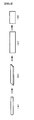
- FIG. 3 is a schematic diagram for describing a production method of rolled copper foil according to an embodiment of the present invention. Note that the shape of the rolled copper foil midway through manufacturing is schematically illustrated. Therefore, the present invention is not limited to the depicted shape.
- a hard copper wire or a soft copper wire (round wire type) having a desired diameter (for example, ⁇ 0.30 mm) is prepared.
- the hard copper wire of the above diameter of ⁇ 0.30 mm can be formed by drawing a soft copper wire having a larger diameter (for example, ⁇ 2.6 mm).
- the soft copper wire of the above diameter of ⁇ 0.30 mm can be formed by conducting further heat treatment (for example, 300°C for 2 hours).
- the hard copper wire having a desired diameter (for example, ⁇ 0.30 mm) or the soft copper wire undergoes rolling to form a final foil shape (for example, a foil having a thickness of 0.080 mm by a width of 0.8 mm).
- Examples of methods for rolling include methods that process by passing the copper wire between two or a plurality of rotating rollers. Note that the roller diameter, number of passes, the existence or absence of a lubricating agent, and the like can be appropriately regulated.
- rolling to form a final copper foil shape may be conducted in two or more steps, and further, a heating treatment may be implemented between the rolling steps when two or more rolling steps are performed.
- a heat treatment (annealing) is conducted on the final copper foil shape that has been formed.
- Preferred conditions for the heat treatment are a heating temperature within a range of not less than 200°C and not higher than 1000°C and a heating time within a range of not less than 0.01 seconds and not longer than 100 seconds (for example, conditions of a heating temperature of 400°C and a heating time of 5 seconds may be conducted).
- examples of methods for carrying out the heat treatment include methods such as heat treatments in which a salt bath is used, heat treatments using a batch furnace, current in-line annealing, and the like.
- methods for heat treatment are not limited to the above methods.
- Cooling thereafter produces the rolled copper foil 2 as illustrated in FIG. 4 .
- a preferred method for cooling is a method for rapid cooling such as cooling with water. Implementing rapid cooling such as cooling with water prevents coarsening of the crystal grain diameter.
- the thickness of the rolled copper foil according to the present invention is not particularly limited, but a range of not less than 0.02 mm and not greater than 0.1 mm is preferred.
- the rolled copper foil according to the present invention has excellent flexibility and excellent flex resistance and therefore has a high degree of freedom in implementation into electronic devices and the like and is thus suited for use as a flexible flat cable (FFC).
- FFC flexible flat cable
- it can be suitably used in a steering roll connector (SRC) which is a configuring component of an airbag system in an automobile, or in a roof harness, door harness, floor harness, and the like.
- SRC steering roll connector
- the rolled copper foil according to the present invention will be described hereinafter in examples, but the present invention is not in any way limited to these examples.
- a soft copper wire of ⁇ 2.6 mm was drawn to prepare a hard copper wire (round wire type) of ⁇ 0.30 mm.
- Rolling was performed on the hard copper wire using a rolling machine (non-lubricated) having a roll with a diameter of ⁇ 100 mm, to form a foil shape having a thickness of 0.080 mm by a width of 0.8 mm.
- a heat treatment was performed on the foil shape under conditions of 400°C for 5 seconds using a salt bath, and after the heat treatment (annealing), rapid cooling by cooling with water was performed to obtain the rolled copper foil.
- a soft copper wire (round wire type) with a diameter of ⁇ 0.30 mm was prepared by conducting a further heat treatment at 300°C for 2 hours, and other than use of the soft copper wire in place of the hard copper wire (round wire type) with a diameter of ⁇ 0.30 mm, a rolled copper foil was obtained according to the method described in example 1-1.
- a rolled copper foil was obtained using the method described in example 1-1 other than changing the temperature at the time of heat treatment (annealing) using a salt bath in the example 1-1 from 400°C to 800°C.
- a rolled copper foil was obtained using the method described in example 1-1 other than not performing any heat treatment (annealing) using a salt bath and subsequent cooling with water in the example 1-2.
- a soft copper wire of ⁇ 2.6 mm was drawn to prepare a hard copper wire (round wire type) of ⁇ 0.20 mm.
- Rolling was performed on the hard copper wire using a rolling machine (non-lubricated) having a roller with a diameter of ⁇ 100 mm, to form a foil shape having a thickness of 0.035 mm by a width of 0.8 mm.
- a heat treatment was performed on the foil shape under conditions of 300°C for 1 second using a salt bath, and after the heat treatment (annealing), rapid cooling by cooling with water was performed to obtain the rolled copper foil.
- a rolled copper foil was obtained using the method described in example 2-1 other than changing the temperature and time at the time of heat treatment (annealing) using a salt bath in the example 2-1 to the conditions given in Table 2.
- a rolled copper foil was obtained using the method described in example 2-1 other than not performing any heat treatment (annealing) using a salt bath and subsequent cooling with water (that is, only interim annealing was performed) in the example 2-1.
- condition 1 and condition 2 are temperature conditions in the testing chamber where the flex resistance test was performed. Condition 1 at high temperature is an accelerated test, and condition 2 indicates a test at room temperature conditions.
- Evaluation: A Those evaluated at 5 million repetitions or more were designated as Evaluation: A, and those evaluated at less than 5 million repetitions were designated as Evaluation: B.
- a tensile strength test was performed on the rolled copper foil and the yield strength was measured, and those having a low yield strength were determined to have excellent flexibility. Those with a yield strength of 200 MPa or below were designated as Evaluation: A, and those having a yield strength that exceeded 200 MPa were designated as Evaluation: B.
- the tensile strength and elongation were measured by conducting a tensile test on the rolled copper foil.
Landscapes
- Chemical & Material Sciences (AREA)
- Engineering & Computer Science (AREA)
- Mechanical Engineering (AREA)
- Organic Chemistry (AREA)
- Materials Engineering (AREA)
- Metallurgy (AREA)
- Thermal Sciences (AREA)
- Crystallography & Structural Chemistry (AREA)
- Physics & Mathematics (AREA)
- Microelectronics & Electronic Packaging (AREA)
- Metal Rolling (AREA)
- Parts Printed On Printed Circuit Boards (AREA)
- Non-Insulated Conductors (AREA)
- Conductive Materials (AREA)
Abstract

(In the above formula (1), (A) represents the area of a region identified through image analysis to have an orientation difference of not less than 1 degree and not greater than 15 degrees, and (B) represents the area of a region identified through image analysis to have an orientation difference of not less than 0 degrees and not greater than 15 degrees).
Description
- The present invention relates to rolled copper foil composed of crystal particles of copper or a copper alloy, and particularly relates to a rolled copper foil used in flexible flat cable and the like where flexion movement is repeated in automotive components and the like.
- Flexible flat cable (FFC), featuring a thin thickness and excellent flexibility, is used in a variety of uses for its high degree of freedom in implementation into electronic devices. It is widely used, for example, in a steering roll connector (SRC) which is a component of an airbag system in an automobile, in a folding part of a folding mobile telephone, in movable parts for digital cameras, printer heads, and the like, and in wiring and the like of movable parts in disk related devices such as a hard disk drive (HDD), digital versatile disc (DVD), compact disk (CD), and the like.
- Note that rolled copper foil has been widely used conventionally in conductor parts for flexible flat cables.
- Here, a rectangular conductor is disclosed in Japanese Unexamined Patent Application Publication No.
2009-048819 - Further, in Japanese Unexamined Patent Application Publication No.
2010-150578 2010-150578 - In Japanese Unexamined Patent Application Publication No.
2001-262296 2001-262296 - However, the conductor such as that in Japanese Unexamined Patent Application Publication No.
2009-048819 - Further, Japanese Unexamined Patent Application Publication No.
2010-150578 - Moreover, Japanese Unexamined Patent Application Publication No.
2001-262296 - In light of the above, an object of the present invention is to provide a rolled copper foil in which the generation of cracks is suppressed even under repeated flexion deformity.
- The above problems for the present invention are resolved by the following means.
- 1. A rolled copper foil composed of crystal particles of copper or a copper alloy, wherein an average particle size of the crystal particles composing the outermost surface is not less than 0.2 µm and not greater than 6 µm; a ratio of the average particle size of the crystal particles composing the outermost surface to a thickness of the rolled copper foil is not less than 1% and not greater than 6%; and an intragranular distortion rate found by the following formula (1) when a cross-section perpendicular to a length direction of the rolled copper foil is analyzed by electron backscatter diffraction (EBSD) is not less than 0.5% and not greater than 10%.

(In the above formula (1), (A) represents the area of a region identified through image analysis to have an orientation difference of not less than 1 degree and not greater than 15 degrees, and (B) represents the area of a region identified through image analysis to have an orientation difference of not less than 0 degrees and not greater than 15 degrees). - 2. The rolled copper foil according to 1, wherein a ratio of the average particle size of the crystal particles composing the outermost surface to a thickness of the rolled copper foil is not less than 1% and not greater than 2%.
- 3. The rolled copper foil according to 1, wherein a ratio of the average particle size of the crystal particles composing the outermost surface to a thickness of the rolled copper foil is greater than 2% and less than 3%.
- 4. The rolled copper foil according to 1, wherein a ratio of the average particle size of the crystal particles composing the outermost surface to a thickness of the rolled copper foil is not less than 3% and not greater than 6%.
- 5. The rolled copper foil according to any one of 1 to 4, wherein a round wire type copper material is formed into a foil shape by rolling.
- 6. The rolled copper foil according to any one of 1 to 5, wherein a thickness of the rolled copper foil is not less than 0.02 mm and not greater than 0.1 mm.
- With the present invention, a rolled copper foil is provided in which the generation of cracks is suppressed even under repeated flexion deformity.
-
-
FIG. 1 is one example of a graph that plots a proportion of regions having an orientation difference in adjacent regions on the horizontal axis and regions having such orientation difference on the vertical axis based on EBSD analysis of the rolled copper foil. -
FIG. 2 is one example of a graph that plots a proportion of regions having an orientation difference in adjacent regions on the horizontal axis and regions having such orientation difference on the vertical axis based on EBSD analysis of the rolled copper foil. -
FIG. 3 is a schematic diagram for describing a production method of rolled copper foil according to an embodiment of the present invention. -
FIG. 4 is a schematic perspective view illustrating rolled copper foil according to an embodiment of the present invention. -
FIG. 5 is a schematic view illustrating the rolled copper foil fixed in a flex testing machine used in flex resistance testing in the examples. - The rolled copper foil according to the present invention is composed of crystal particles of copper or a copper alloy and satisfies the following requirements.
- An average particle size of the crystal particles composing the outermost surface is not less than 0.2 µm and not greater than 6 µm
- A ratio of the average particle size of the crystal particles composing the outermost surface to a thickness of the rolled copper foil is not less than 1% and not greater than 6%
- An intragranular distortion rate found by the following formula (1) when a cross-section perpendicular to a length direction of the rolled copper foil is analyzed by electron backscatter diffraction (EBSD) is not less than 0.5% and not greater than 10%

(In the above formula (1), (A) represents the area of a region identified through image analysis to have an orientation difference of not less than 1 degree and not greater than 15 degrees, and (B) represents the area of a region identified through image analysis to have an orientation difference of not less than 0 degrees and not greater than 15 degrees). - The rolled copper foil according to the present invention as described above has an intragranular distortion rate of not less than 0.5% and not greater than 10%. The intragranular distortion rate, as expressed by formula (1), is a ratio of the area of a region with an orientation difference of not less than 1 degree and not greater than 15 degrees to the area of a region with an orientation difference of not less than 0 degrees and not greater than 15 degrees, and of the region with an orientation difference of not less than 0 degrees and not greater than 15 degrees recognized as intragranular distortion, a majority is occupied by an orientation difference of not less than 0 degrees and less than 1 degree, showing that a ratio for orientation difference of not less than 1 degree and not greater than 15 degrees is extremely small. In other words, this indicates that the crystals composing the rolled copper foil contain virtually no intragranular distortion.
- Further, according to the above, an average particle size of the crystal particles composing the outermost surface is not less than 0.2 µm and not greater than 6 µm, and a ratio of the average particle size of the crystal particles composing the outermost surface to a thickness of the rolled copper foil is not less than 1% and not greater than 6%, so the particle size of the crystal particles of the outermost surface is extremely small.
- The rolled copper foil according to the present invention that satisfies the above composition can suppress the generation of cracks even when under repeated flexion deformity, and as a result, can achieve a long life.
- In the present invention, an intragranular distortion rate, found by the following formula (1) when a cross-section perpendicular to a length direction of the rolled copper foil is analyzed by electron backscatter diffraction (EBSD), is not less than 0.5% and not greater than 10%. When the intragranular distortion rate exceeds 10%, early breakage becomes a problem due to coarsening of the crystal particles when undergoing repeated flexion deformity. On the other hand, when the intragranular distortion rate is below 0.5%, producibility is poor because controlling heat treatment is difficult.
- The above intragranular distortion rate is measured according to the following method.
- The rolled copper foil is cut in a direction perpendicular to the length direction and that cross section is analyzed using electron backscatter diffraction (EBSD). With EBSD analysis, the portion where the orientation difference in adjacent measured regions exceeds 15 degrees is identified as a crystal grain boundary, and that having an orientation difference up to 15 degrees is recognized as an intragranular distortion. However, the orientation difference measured between not less than 0 degrees and less than 1 degree is understood to be an unproblematic intragranular distortion. The reason is because distortions in this range normally do not disappear much even when undergoing annealing treatment and the like. Therefore, the distortion condition of the rolled copper foil can be evaluated by calculating the regions with an orientation difference not less than 1 degree and not greater than 15 degrees from among regions having an orientation difference from 0 degrees to 15 degrees.
- Therefore, by extracting the portions of orientation difference from 0 degrees to 15 degrees, measuring the area of regions in the cross-section with an orientation difference of not less than 1 degree and not greater than 15 degrees and the area of regions with an orientation difference of not less than 0 degrees and not greater than 15 degrees, the intragranular distortion rate can be found using the formula (1).
- The smaller the value of the intragranular distortion rate is, the smaller the intragranular distortion existing in the rolled copper foil is.
-
FIG. 1 shows one example of an orientation difference of adjacent measurement regions and the existing proportion thereof. InFIG. 1 , region I is an existing proportion of an orientation difference between not less than 0 degrees and less than 1 degree, and region II shows an existing proportion of an orientation difference between not less than 1 degree and not greater than 15 degrees. Accordingly, in the relationship in the above formula (1), (A) corresponds to region II and (B) corresponds to a region that is the sum of region I and region II. In other words, it is understood that the smaller region II expressed by (A) is, the smaller the intragranular distortion rate is. AlthoughFIG. 2 also shows an example of an orientation difference of adjacent measurement regions and the existing proportion thereof, the region II in the example inFIG. 2 is larger than the example inFIG. 1 . That is to say, a rolled copper foil in this state has a higher intragranular distortion rate than the example inFIG. 1 because (A) is larger in the above formula (1). - The inventors, in the course of their research, discovered that when the intragranular distortion rate satisfies a predetermined value, a rolled copper foil can be provided in which the generation of cracks can be suppressed even when undergoing repeated flexion deformity.
- In the present invention, an average particle size of the crystal particles composing the outermost surface is not less than 0.2 µm and not greater than 6 µm, and a ratio of the average particle size of the crystal particles composing the outermost surface to a thickness of the rolled copper foil is not less than 1% and not greater than 6%. When the average particle size exceeds 6 µm or when the ratio of the average particle size exceeds 6%, the generation of cracks when undergoing repeated flexion deformity becomes problematic. On the other hand, when the average particle size is less than 0.2 µm or when the ratio of the average particle size is less than 1%, there is a problem in that the rolled copper foil has poor flexibility which makes wiring difficult.
- Note that from the perspective of favorable bending, and from a point of view that the generation of cracking under repeated flexion deformity is more effectively suppressed, a ratio of the average particle size described above is better when smaller in the order of the following ranges: not less than 1% and not greater than 2%, greater than 2% and less than 3%, and not less than 3% and not greater than 6%.
- At the same time, from the perspective of favorable flexing, and from a point of view that yield strength is lower and there is more flexibility the larger the ratio of the average particle size described above, a ratio of the average particle size is better when larger in the order of the following ranges: not less than 3% and not greater than 6%, greater than 2% and less than 3%, and not less than 1% and not greater than 2%.
- The average particle size and the ratio of the average particle size are measured according to the following method.
- A rolled copper foil is cut in a direction perpendicular to the length direction and a cross-section thereof is analyzed using EBSD. With EBSD analysis, the portion where the orientation difference exceeds 15 degrees is identified as a grain boundary and an image of the crystal grain is obtained. With this image, a number (K) of crystal grains composing the outermost surface in a specified width direction length (H) (at least not less than 40 µm) is found, and the width direction length (H) is divided by the number (K) of the crystal grains to get the average particle size of the crystal grains composing the outermost surface. Further dividing this value of the average particle size by the thickness of the rolled copper foil allows the ratio of the average particle size of crystal grains composing the outermost surface to the thickness of the rolled copper foil to be found.
- In the production of the rolled copper foil according to the present invention, first, round wire type copper material is formed into a predetermined copper foil shape by rolling (rolling process), and thereafter, production is achieved by performing heat treatment (annealing) and cooling (annealing process). Note that, in the process for forming into the predetermined copper foil shape, rolling may be performed in multiple steps, and formation may be performed using methods in combination other than rolling. Further, heat treatment may be implemented at a step prior to forming the predetermined copper foil shape (prior to forming the final shape).
- In addition to material composed of copper, material composed of a copper alloy may also be used as the copper material.
- Examples of copper in the material composed of copper or the material composed of a copper alloy include tough pitch copper, oxygen-free copper, copper alloys containing a small amount of silver (Ag) or tin (Sn), and the like.
- Note that what is important here is the heating temperature and the heating time during annealing.
- With the rolled copper foil of the present invention, the ratio of the average particle size of crystal particles composing the outermost surface to the thickness of the rolled copper foil, and the intragranular distortion rate, are within the ranges described above. Examples of methods to control the intragranular distortion rate within the range include methods that adjust the heating temperature and heating time in the annealing process. Increasing the heating temperature and extending the heating time can further remove intragranular distortion, that is, the intragranular distortion rate tends to be reduced. However, if the heating temperature is too high or the heating time is too long, the particle size of the crystal grains become larger than desired resulting in adverse effects on bending, and therefore, appropriate conditions must be set according to the temper and wire diameter of the introduced wire prior to rolling and the sheet thickness and the like after rolling.
- Further, examples of methods for controlling the ratio of the average particle size of the crystal grains to the thickness of the rolled copper foil to be within the range include methods for adjusting the heating temperature and the heating time in the annealing process. Decreasing the heating temperature or shortening the heating time maintains a small average particle size of the crystal particles, that is, the ratio of the average particle size of the crystal grains to the thickness of the rolled copper foil tends to be within the range. However, if the heating temperature is too low or the heating time is too short, intragranular distortion may remain having adverse effects on bending, and therefore, appropriate conditions must be set according to temper and wire diameter of the introduced wire prior to rolling and sheet thickness and the like after rolling.
- Here, a description of one example of producing a rolled copper foil according to the present invention will be given with reference to figures.
-
FIG. 3 is a schematic diagram for describing a production method of rolled copper foil according to an embodiment of the present invention. Note that the shape of the rolled copper foil midway through manufacturing is schematically illustrated. Therefore, the present invention is not limited to the depicted shape. - As illustrated by step (a) in
FIG. 3 , first, a hard copper wire or a soft copper wire (round wire type) having a desired diameter (for example, Φ 0.30 mm) is prepared. For example, the hard copper wire of the above diameter of Φ 0.30 mm can be formed by drawing a soft copper wire having a larger diameter (for example, Φ 2.6 mm). Further, after the soft copper wire having a larger diameter (for example, Φ 2.6 mm) is drawn, the soft copper wire of the above diameter of Φ 0.30 mm can be formed by conducting further heat treatment (for example, 300°C for 2 hours). - Next, as illustrated by step (b) in
FIG. 3 , the hard copper wire having a desired diameter (for example, Φ 0.30 mm) or the soft copper wire undergoes rolling to form a final foil shape (for example, a foil having a thickness of 0.080 mm by a width of 0.8 mm). - Examples of methods for rolling include methods that process by passing the copper wire between two or a plurality of rotating rollers. Note that the roller diameter, number of passes, the existence or absence of a lubricating agent, and the like can be appropriately regulated.
- Note that rolling to form a final copper foil shape may be conducted in two or more steps, and further, a heating treatment may be implemented between the rolling steps when two or more rolling steps are performed.
- Next, as illustrated by step (c) in
FIG. 3 , a heat treatment (annealing) is conducted on the final copper foil shape that has been formed. Preferred conditions for the heat treatment are a heating temperature within a range of not less than 200°C and not higher than 1000°C and a heating time within a range of not less than 0.01 seconds and not longer than 100 seconds (for example, conditions of a heating temperature of 400°C and a heating time of 5 seconds may be conducted). - Note that examples of methods for carrying out the heat treatment (annealing) include methods such as heat treatments in which a salt bath is used, heat treatments using a batch furnace, current in-line annealing, and the like. However, methods for heat treatment are not limited to the above methods.
- Cooling thereafter (step (d)) produces the rolled
copper foil 2 as illustrated inFIG. 4 . Note that a preferred method for cooling is a method for rapid cooling such as cooling with water. Implementing rapid cooling such as cooling with water prevents coarsening of the crystal grain diameter. - Note that the thickness of the rolled copper foil according to the present invention is not particularly limited, but a range of not less than 0.02 mm and not greater than 0.1 mm is preferred.
- The rolled copper foil according to the present invention has excellent flexibility and excellent flex resistance and therefore has a high degree of freedom in implementation into electronic devices and the like and is thus suited for use as a flexible flat cable (FFC). For example, it can be suitably used in a steering roll connector (SRC) which is a configuring component of an airbag system in an automobile, or in a roof harness, door harness, floor harness, and the like.
- Note that the disclosure of Japanese Patent Application No.
2011-248097 - All documents, patent applications, and technical specifications described in this specification are incorporated into this specification by reference, and the incorporation of each document, patent application, and technical specification by reference is to the same extent as when specifically and individually described.
- The rolled copper foil according to the present invention will be described hereinafter in examples, but the present invention is not in any way limited to these examples.
- As illustrated in
FIG. 3 , a soft copper wire of Φ 2.6 mm was drawn to prepare a hard copper wire (round wire type) of Φ 0.30 mm. Rolling was performed on the hard copper wire using a rolling machine (non-lubricated) having a roll with a diameter of Φ 100 mm, to form a foil shape having a thickness of 0.080 mm by a width of 0.8 mm. Next, a heat treatment (annealing) was performed on the foil shape under conditions of 400°C for 5 seconds using a salt bath, and after the heat treatment (annealing), rapid cooling by cooling with water was performed to obtain the rolled copper foil. - Using the method described above, the average particle size of crystal grains composing the outermost surface and the ratio of the average particle size to the thickness of the rolled copper foil were found, and the intragranular distortion rate was found using the formula (1) described above for use at the time of EBSD analysis of a cross-section perpendicular to the length direction of the rolled copper foil. The results are shown in Table 1.
- After the soft copper wire having a diameter of Φ 2.6 mm was drawn in the example 1-1, a soft copper wire (round wire type) with a diameter of Φ 0.30 mm was prepared by conducting a further heat treatment at 300°C for 2 hours, and other than use of the soft copper wire in place of the hard copper wire (round wire type) with a diameter of Φ 0.30 mm, a rolled copper foil was obtained according to the method described in example 1-1.
- A rolled copper foil was obtained using the method described in example 1-1 other than changing the temperature at the time of heat treatment (annealing) using a salt bath in the example 1-1 from 400°C to 800°C.
- A rolled copper foil was obtained using the method described in example 1-1 other than not performing any heat treatment (annealing) using a salt bath and subsequent cooling with water in the example 1-2.
- Using an FPC flex testing machine (FT-2130) made by Ueshima Seisakusho shown in
FIG. 5 , the rolledcopper foil 2 was secured in asample fixing plate 4 and anoperation plate 6, and flex testing was performed by operating theoperation plate 6 by amotor 8. Note that, flex testing was repeated at a flexion R: 12.5 mm, stroke S: ±13 mm, environmental temperature: 85°C, rotational speed: 900 RPM, and break definition: initial resistance value+500 Ω, until a break was verified. - Those evaluated at 5 million repetitions or more were designated as A, and those evaluated at less than 5 million repetitions were designated as B.
- A tensile strength test was performed on the rolled copper foil and the yield strength was measured. Those having a low yield strength with excellent flexibility were designated as (Evaluation: A) and those having a high yield strength were designated as (Evaluation: B). As shown in the following Table 1, in example 1-1, 1-2, and comparative example 1-1, the ratio of average particle size of crystal grains composing the outermost surface to the thickness of the rolled copper foil was not too small and was considered to provide results for excellent flexing.
Table 1 Copper Wire After Rolling Heat Treatment (Annealing) Top Surface Grain Diameter [µm] Ratio of Particle Size to Thickness [%] Intragranular Distortion Rate [%] Evaluation Diameter [mm] Temper Thickness [mm] Width [mm] Temperature [°C] Time [sec] Number of Flexes (Times) Flexing Property Working Example 1-1 0.3 H 0.08 0.8 400 5 1.6 2.0 3.2 10 million or more A A Working Example 1-2 0.3 0 0.08 0.8 400 5 2.0 2.5 1.4 10 million or more A A Comparative Example 1-1 0.3 H 0.08 0.8 800 5 8.2 10.3 1.0 2 million B A Comparative Example 1-2 0.3 0 0.08 0.8 None None 1.2 1.5 77.0 50,000 B B - As illustrated in
FIG. 3 , a soft copper wire of Φ 2.6 mm was drawn to prepare a hard copper wire (round wire type) of Φ 0.20 mm. Rolling was performed on the hard copper wire using a rolling machine (non-lubricated) having a roller with a diameter of Φ 100 mm, to form a foil shape having a thickness of 0.035 mm by a width of 0.8 mm. Next, a heat treatment (annealing) was performed on the foil shape under conditions of 300°C for 1 second using a salt bath, and after the heat treatment (annealing), rapid cooling by cooling with water was performed to obtain the rolled copper foil. - Using the method described above, the average particle size of crystal grains composing the outermost surface and the ratio of the average particle size to the thickness of the rolled copper foil were found, and the intragranular distortion rate was found using the formula (1) described above for use at the time of EBSD analysis of a cross-section orthogonal to the length direction of the rolled copper foil. The results are shown in Table 2.
- A rolled copper foil was obtained using the method described in example 2-1 other than changing the temperature and time at the time of heat treatment (annealing) using a salt bath in the example 2-1 to the conditions given in Table 2.
- A rolled copper foil was obtained using the method described in example 2-1 other than not performing any heat treatment (annealing) using a salt bath and subsequent cooling with water (that is, only interim annealing was performed) in the example 2-1.
- Using an FPC flex testing machine (FT-2130) made by Ueshima Seisakusho shown in
FIG. 5 , the rolledcopper foil 2 was secured in thesample fixing plate 4 and theoperation plate 6, and flex testing was performed by operating theoperation plate 6 by themotor 8. Note that, flex testing was repeated at a flexion R: 7.5 mm, stroke S: ±13 mm, environmental temperature:condition 1 = 85°C andcondition 2 = 20°C, rotational speed: 900 RPM, and break definition: initial resistance value+500 Ω, until a break was verified. Note thatcondition 1 andcondition 2 are temperature conditions in the testing chamber where the flex resistance test was performed.Condition 1 at high temperature is an accelerated test, andcondition 2 indicates a test at room temperature conditions. - Those evaluated at 5 million repetitions or more were designated as Evaluation: A, and those evaluated at less than 5 million repetitions were designated as Evaluation: B.
- A tensile strength test was performed on the rolled copper foil and the yield strength was measured, and those having a low yield strength were determined to have excellent flexibility. Those with a yield strength of 200 MPa or below were designated as Evaluation: A, and those having a yield strength that exceeded 200 MPa were designated as Evaluation: B.
- As shown in the following Table 2, in Working Examples 2-1 to 2-4, the ratio of average particle size of crystal grains composing the outermost surface to the thickness of the rolled copper foil was not too small and was considered to provide results for excellent flexing.
- The tensile strength and elongation were measured by conducting a tensile test on the rolled copper foil.
- The tensile test when measuring the yield strength, the tensile strength, and the elongation was performed using a rectangular conductor of Table 2 on the test piece, and the test method was performed in compliance with JIS-Z2241 (1998).
Table 2 Copper Wire After Rolling Heat Treatment (Annealing) Outer Surface Grain Diameter [µm] Ratio of Particle Size to Thickness [%] Intragranular Distortion Rate [%] Evaluation Diameter [mm] Temper Thickness [mm] Width [mm] Temperature [°C] Time [sec] Number of Flexes Flexing Property (Yeld Strength) [MPa] Tensile Strength [MPa] Elongation [%] Condition 1 (Times) Condition 2 (Times) Working Example 2-1 0.2 H 0.035 0.8 300 1 0.96 2.7 7.8 5 million or more A 5 million or more A 135.6 A 231.2 31.6 Working Example 2-2 0.2 H 0.035 0.8 300 5 0.99 2.8 7.9 5 million or more A 5 million or more A 129.8 A 234.0 30.8 Working Example 2-3 0.2 H 0.035 0.8 500 1 1.32 3.8 5.0 5 million or more A 5 million or more A 95.0 A 216.8 24.5 Working Example 2-4 0.2 H 0.035 0.8 500 5 1.46 4.2 3.7 5 million or more A 5 million or more A 83.7 A 208.3 21.4 Comparative Example 2-1 0.2 H 0.035 0.8 none none 0.71 2.0 41.8 - 3.27 million B 384.0 B 424 2.7 -
- 2 rolled copper foil
- 4 sample fixing plate
- 6 operation plate
- 8 motor
Claims (6)
- A rolled copper foil comprising crystal particles of copper or a copper alloy, the rolled copper foil comprising:an average particle size of the crystal particles composing the outermost surface of not less than 0.2 µm and not greater than 6 µm;a ratio of the average particle size of the crystal particles composing the outermost surface to a thickness of the rolled copper foil of not less than 1% and not greater than 6%;and an intragranular distortion rate, found by the following formula (1) when a cross-section perpendicular to a length direction of the rolled copper foil is analyzed by electron backscatter diffraction (EBSD), of not less than 0.5% and not greater than 10%

(provided that in the formula (1), (A) represents an area of a region identified through image analysis to have an orientation difference of not less than 1 degree and not greater than 15 degrees, and (B) represents an area of a region identified through image analysis to have an orientation difference of not less than 0 degrees and not greater than 15 degrees). - The rolled copper foil according to claim 1, wherein a ratio of the average particle size of the crystal particles composing the outermost surface to a thickness of the rolled copper foil is not less than 1% and not greater than 2%.
- The rolled copper foil according to claim 1, wherein a ratio of the average particle size of the crystal particles composing the outermost surface to a thickness of the rolled copper foil is more than 2% and less than 3%.
- The rolled copper foil according to claim 1, wherein a ratio of the average particle size of the crystal particles composing the outermost surface to a thickness of the rolled copper foil is not less than 3% and not greater than 6%.
- The rolled copper foil according to any one of claims 1 to 4, wherein a round wire type copper material is formed into a foil shape by rolling.
- The rolled copper foil according to any one of claims 1 to 5, wherein a thickness of the rolled copper foil is not less than 0.02 mm and not greater than 0.1 mm.
Applications Claiming Priority (2)
| Application Number | Priority Date | Filing Date | Title |
|---|---|---|---|
| JP2011248097 | 2011-11-11 | ||
| PCT/JP2012/079300 WO2013069800A1 (en) | 2011-11-11 | 2012-11-12 | Rolled copper foil |
Publications (3)
| Publication Number | Publication Date |
|---|---|
| EP2765215A1 true EP2765215A1 (en) | 2014-08-13 |
| EP2765215A4 EP2765215A4 (en) | 2015-04-29 |
| EP2765215B1 EP2765215B1 (en) | 2017-05-03 |
Family
ID=48290165
Family Applications (1)
| Application Number | Title | Priority Date | Filing Date |
|---|---|---|---|
| EP12848008.4A Active EP2765215B1 (en) | 2011-11-11 | 2012-11-12 | Rolled copper foil |
Country Status (6)
| Country | Link |
|---|---|
| US (1) | US9457389B2 (en) |
| EP (1) | EP2765215B1 (en) |
| JP (1) | JP5342712B1 (en) |
| KR (1) | KR101948958B1 (en) |
| CN (1) | CN103917683B (en) |
| WO (1) | WO2013069800A1 (en) |
Cited By (2)
| Publication number | Priority date | Publication date | Assignee | Title |
|---|---|---|---|---|
| CN107109534A (en) * | 2014-12-12 | 2017-08-29 | 新日铁住金株式会社 | Oriented copper board, copper foil laminated board, flexible circuit board and electronic equipment |
| EP3503314A4 (en) * | 2016-08-16 | 2020-04-08 | Furukawa Electric Co., Ltd. | ROTATING CONNECTOR DEVICE |
Families Citing this family (4)
| Publication number | Priority date | Publication date | Assignee | Title |
|---|---|---|---|---|
| EP3128036B1 (en) | 2014-03-31 | 2020-07-01 | Furukawa Electric Co. Ltd. | Rolled copper foil, method for producing rolled copper foil, flexible flat cable, and method for producing flexible flat cable |
| CN107429324B (en) * | 2015-04-01 | 2019-12-17 | 古河电气工业株式会社 | Flat rolled copper foil, flexible flat cable, rotary connector and manufacturing method of flat rolled copper foil |
| JP6928831B2 (en) * | 2017-07-26 | 2021-09-01 | 古河電気工業株式会社 | Manufacturing method of conductors constituting the flat cable of the rotary connector device |
| CN118588355B (en) * | 2024-06-28 | 2025-04-04 | 广东松田科技股份有限公司 | Composite insulation layer electromagnetic wire and manufacturing method thereof |
Family Cites Families (18)
| Publication number | Priority date | Publication date | Assignee | Title |
|---|---|---|---|---|
| KR940010455B1 (en) * | 1992-09-24 | 1994-10-22 | 김영길 | Copper (Cu) alloy with high strength, excellent electrical conductivity and thermal stability and its manufacturing method |
| JP2898627B2 (en) * | 1997-03-27 | 1999-06-02 | 日鉱金属株式会社 | Copper alloy foil |
| JP3856582B2 (en) * | 1998-11-17 | 2006-12-13 | 日鉱金属株式会社 | Rolled copper foil for flexible printed circuit board and method for producing the same |
| JP3514180B2 (en) * | 1999-08-24 | 2004-03-31 | 日立電線株式会社 | Method for producing rolled copper foil |
| JP2001262296A (en) | 2000-03-17 | 2001-09-26 | Nippon Mining & Metals Co Ltd | Rolled copper foil and method for producing the same |
| JP4401180B2 (en) * | 2004-01-30 | 2010-01-20 | 日鉱金属株式会社 | Rolled copper foil, method for producing the same, and laminated substrate |
| JP5170866B2 (en) * | 2006-10-10 | 2013-03-27 | 古河電気工業株式会社 | Copper alloy material for electric and electronic parts and method for producing the same |
| US7789977B2 (en) * | 2006-10-26 | 2010-09-07 | Hitachi Cable, Ltd. | Rolled copper foil and manufacturing method thereof |
| JP4466688B2 (en) * | 2007-07-11 | 2010-05-26 | 日立電線株式会社 | Rolled copper foil |
| JP2009048819A (en) | 2007-08-16 | 2009-03-05 | Hitachi Cable Ltd | Flat conductor and flat cable using the same |
| JP2009084593A (en) * | 2007-09-27 | 2009-04-23 | Nikko Kinzoku Kk | Cu-Cr-Si-BASED ALLOY FOIL |
| US20090173414A1 (en) * | 2008-01-08 | 2009-07-09 | Takemi Muroga | Rolled Copper Foil and Manufacturing Method of Rolled Copper Foil |
| WO2010001812A1 (en) * | 2008-06-30 | 2010-01-07 | 新日鐵化学株式会社 | Flexible circuit board and method for producing same and bend structure of flexible circuit board |
| JP5390852B2 (en) | 2008-12-24 | 2014-01-15 | 株式会社Shカッパープロダクツ | Rolled copper foil |
| JP4563495B1 (en) * | 2009-04-27 | 2010-10-13 | Dowaメタルテック株式会社 | Copper alloy sheet and manufacturing method thereof |
| JP4992940B2 (en) * | 2009-06-22 | 2012-08-08 | 日立電線株式会社 | Rolled copper foil |
| JP5203418B2 (en) | 2010-05-27 | 2013-06-05 | 古河電気工業株式会社 | Optical fiber strand and optical fiber colored core wire for water immersion detection |
| JP4888586B2 (en) * | 2010-06-18 | 2012-02-29 | 日立電線株式会社 | Rolled copper foil |
-
2012
- 2012-11-12 EP EP12848008.4A patent/EP2765215B1/en active Active
- 2012-11-12 KR KR1020147012377A patent/KR101948958B1/en active Active
- 2012-11-12 WO PCT/JP2012/079300 patent/WO2013069800A1/en not_active Ceased
- 2012-11-12 JP JP2013512694A patent/JP5342712B1/en active Active
- 2012-11-12 CN CN201280055281.XA patent/CN103917683B/en active Active
-
2014
- 2014-05-08 US US14/273,525 patent/US9457389B2/en active Active
Non-Patent Citations (2)
| Title |
|---|
| See also references of WO2013069800A1 * |
| TAKAAKI HATANO, YOSHIO KUROSAWA, JUNJI MIYAKE: "Effect of material processing on fatigue of FPC rolled copper foil", JOURNAL OF ELECTRONIC MATERIALS, vol. 29, no. 5, 2000, - 2000, pages 611-616, XP002737045, * |
Cited By (3)
| Publication number | Priority date | Publication date | Assignee | Title |
|---|---|---|---|---|
| CN107109534A (en) * | 2014-12-12 | 2017-08-29 | 新日铁住金株式会社 | Oriented copper board, copper foil laminated board, flexible circuit board and electronic equipment |
| CN107109534B (en) * | 2014-12-12 | 2018-11-09 | 新日铁住金株式会社 | Oriented copper board, copper foil laminated board, flexible circuit board and electronic equipment |
| EP3503314A4 (en) * | 2016-08-16 | 2020-04-08 | Furukawa Electric Co., Ltd. | ROTATING CONNECTOR DEVICE |
Also Published As
| Publication number | Publication date |
|---|---|
| KR101948958B1 (en) | 2019-02-15 |
| KR20140093675A (en) | 2014-07-28 |
| EP2765215B1 (en) | 2017-05-03 |
| US9457389B2 (en) | 2016-10-04 |
| CN103917683A (en) | 2014-07-09 |
| JPWO2013069800A1 (en) | 2015-04-02 |
| WO2013069800A1 (en) | 2013-05-16 |
| US20140335372A1 (en) | 2014-11-13 |
| JP5342712B1 (en) | 2013-11-13 |
| CN103917683B (en) | 2016-02-24 |
| EP2765215A4 (en) | 2015-04-29 |
Similar Documents
| Publication | Publication Date | Title |
|---|---|---|
| JP6851963B2 (en) | Manufacturing method of flat rolled copper foil, flexible flat cable, rotary connector and flat rolled copper foil | |
| EP2765215B1 (en) | Rolled copper foil | |
| EP2592164B1 (en) | Cu-ni-si copper alloy plate with excellent deep-draw characteristics and production method thereof | |
| EP2463393A1 (en) | Copper alloy | |
| EP2343388B1 (en) | Method of producinga Cu-Mg-P based copper alloy material | |
| JP5281031B2 (en) | Cu-Ni-Si alloy with excellent bending workability | |
| EP2256219A1 (en) | Copper alloy material | |
| EP2333128A1 (en) | Copper alloy material for electrical/electronic component | |
| US10522268B2 (en) | Rolled copper foil, method of manufacturing a rolled copper foil, flexible flat cable, and method of manufacturing a flexible flat cable | |
| EP2835433A1 (en) | Cu-mg-p-based copper alloy plate having excellent fatigue resistance, and method for manufacturing same | |
| WO2016006053A1 (en) | Copper alloy sheet material, connector, and method for producing copper alloy sheet material | |
| KR20160102989A (en) | Copper alloy sheet material, connector, and production method for copper alloy sheet material | |
| JP6696770B2 (en) | Copper alloy plate and connector | |
| CN103547692A (en) | Cu-Ni-Si copper alloy sheet with excellent deep drawability and process for producing same | |
| JP6147077B2 (en) | Rolled copper foil and method for producing rolled copper foil | |
| CN110462075B (en) | Copper alloy strip with improved dimensional accuracy after stamping | |
| JP5011586B2 (en) | Copper alloy sheet with improved bending workability and fatigue characteristics and its manufacturing method | |
| JP5839950B2 (en) | Rolled copper foil | |
| CN111112330B (en) | A processing method for improving the strength of copper strip without causing anisotropy | |
| JP6154996B2 (en) | High-strength copper alloy material and manufacturing method thereof |
Legal Events
| Date | Code | Title | Description |
|---|---|---|---|
| PUAI | Public reference made under article 153(3) epc to a published international application that has entered the european phase |
Free format text: ORIGINAL CODE: 0009012 |
|
| 17P | Request for examination filed |
Effective date: 20140507 |
|
| AK | Designated contracting states |
Kind code of ref document: A1 Designated state(s): AL AT BE BG CH CY CZ DE DK EE ES FI FR GB GR HR HU IE IS IT LI LT LU LV MC MK MT NL NO PL PT RO RS SE SI SK SM TR |
|
| DAX | Request for extension of the european patent (deleted) | ||
| RA4 | Supplementary search report drawn up and despatched (corrected) |
Effective date: 20150330 |
|
| RIC1 | Information provided on ipc code assigned before grant |
Ipc: C22F 1/08 20060101AFI20150320BHEP Ipc: H05K 1/09 20060101ALI20150320BHEP Ipc: C22F 1/00 20060101ALI20150320BHEP Ipc: B21B 1/40 20060101ALI20150320BHEP Ipc: B21B 3/00 20060101ALI20150320BHEP |
|
| 17Q | First examination report despatched |
Effective date: 20160615 |
|
| GRAP | Despatch of communication of intention to grant a patent |
Free format text: ORIGINAL CODE: EPIDOSNIGR1 |
|
| STAA | Information on the status of an ep patent application or granted ep patent |
Free format text: STATUS: GRANT OF PATENT IS INTENDED |
|
| INTG | Intention to grant announced |
Effective date: 20161125 |
|
| GRAS | Grant fee paid |
Free format text: ORIGINAL CODE: EPIDOSNIGR3 |
|
| GRAA | (expected) grant |
Free format text: ORIGINAL CODE: 0009210 |
|
| STAA | Information on the status of an ep patent application or granted ep patent |
Free format text: STATUS: THE PATENT HAS BEEN GRANTED |
|
| AK | Designated contracting states |
Kind code of ref document: B1 Designated state(s): AL AT BE BG CH CY CZ DE DK EE ES FI FR GB GR HR HU IE IS IT LI LT LU LV MC MK MT NL NO PL PT RO RS SE SI SK SM TR |
|
| REG | Reference to a national code |
Ref country code: GB Ref legal event code: FG4D |
|
| REG | Reference to a national code |
Ref country code: AT Ref legal event code: REF Ref document number: 890069 Country of ref document: AT Kind code of ref document: T Effective date: 20170515 Ref country code: CH Ref legal event code: EP |
|
| REG | Reference to a national code |
Ref country code: IE Ref legal event code: FG4D |
|
| REG | Reference to a national code |
Ref country code: DE Ref legal event code: R096 Ref document number: 602012032088 Country of ref document: DE |
|
| REG | Reference to a national code |
Ref country code: NL Ref legal event code: MP Effective date: 20170503 |
|
| REG | Reference to a national code |
Ref country code: AT Ref legal event code: MK05 Ref document number: 890069 Country of ref document: AT Kind code of ref document: T Effective date: 20170503 |
|
| REG | Reference to a national code |
Ref country code: LT Ref legal event code: MG4D |
|
| PG25 | Lapsed in a contracting state [announced via postgrant information from national office to epo] |
Ref country code: AT Free format text: LAPSE BECAUSE OF FAILURE TO SUBMIT A TRANSLATION OF THE DESCRIPTION OR TO PAY THE FEE WITHIN THE PRESCRIBED TIME-LIMIT Effective date: 20170503 Ref country code: NO Free format text: LAPSE BECAUSE OF FAILURE TO SUBMIT A TRANSLATION OF THE DESCRIPTION OR TO PAY THE FEE WITHIN THE PRESCRIBED TIME-LIMIT Effective date: 20170803 Ref country code: HR Free format text: LAPSE BECAUSE OF FAILURE TO SUBMIT A TRANSLATION OF THE DESCRIPTION OR TO PAY THE FEE WITHIN THE PRESCRIBED TIME-LIMIT Effective date: 20170503 Ref country code: LT Free format text: LAPSE BECAUSE OF FAILURE TO SUBMIT A TRANSLATION OF THE DESCRIPTION OR TO PAY THE FEE WITHIN THE PRESCRIBED TIME-LIMIT Effective date: 20170503 Ref country code: FI Free format text: LAPSE BECAUSE OF FAILURE TO SUBMIT A TRANSLATION OF THE DESCRIPTION OR TO PAY THE FEE WITHIN THE PRESCRIBED TIME-LIMIT Effective date: 20170503 Ref country code: ES Free format text: LAPSE BECAUSE OF FAILURE TO SUBMIT A TRANSLATION OF THE DESCRIPTION OR TO PAY THE FEE WITHIN THE PRESCRIBED TIME-LIMIT Effective date: 20170503 Ref country code: GR Free format text: LAPSE BECAUSE OF FAILURE TO SUBMIT A TRANSLATION OF THE DESCRIPTION OR TO PAY THE FEE WITHIN THE PRESCRIBED TIME-LIMIT Effective date: 20170804 |
|
| PG25 | Lapsed in a contracting state [announced via postgrant information from national office to epo] |
Ref country code: PL Free format text: LAPSE BECAUSE OF FAILURE TO SUBMIT A TRANSLATION OF THE DESCRIPTION OR TO PAY THE FEE WITHIN THE PRESCRIBED TIME-LIMIT Effective date: 20170503 Ref country code: LV Free format text: LAPSE BECAUSE OF FAILURE TO SUBMIT A TRANSLATION OF THE DESCRIPTION OR TO PAY THE FEE WITHIN THE PRESCRIBED TIME-LIMIT Effective date: 20170503 Ref country code: SE Free format text: LAPSE BECAUSE OF FAILURE TO SUBMIT A TRANSLATION OF THE DESCRIPTION OR TO PAY THE FEE WITHIN THE PRESCRIBED TIME-LIMIT Effective date: 20170503 Ref country code: RS Free format text: LAPSE BECAUSE OF FAILURE TO SUBMIT A TRANSLATION OF THE DESCRIPTION OR TO PAY THE FEE WITHIN THE PRESCRIBED TIME-LIMIT Effective date: 20170503 Ref country code: IS Free format text: LAPSE BECAUSE OF FAILURE TO SUBMIT A TRANSLATION OF THE DESCRIPTION OR TO PAY THE FEE WITHIN THE PRESCRIBED TIME-LIMIT Effective date: 20170903 Ref country code: BG Free format text: LAPSE BECAUSE OF FAILURE TO SUBMIT A TRANSLATION OF THE DESCRIPTION OR TO PAY THE FEE WITHIN THE PRESCRIBED TIME-LIMIT Effective date: 20170803 Ref country code: NL Free format text: LAPSE BECAUSE OF FAILURE TO SUBMIT A TRANSLATION OF THE DESCRIPTION OR TO PAY THE FEE WITHIN THE PRESCRIBED TIME-LIMIT Effective date: 20170503 |
|
| PG25 | Lapsed in a contracting state [announced via postgrant information from national office to epo] |
Ref country code: SK Free format text: LAPSE BECAUSE OF FAILURE TO SUBMIT A TRANSLATION OF THE DESCRIPTION OR TO PAY THE FEE WITHIN THE PRESCRIBED TIME-LIMIT Effective date: 20170503 Ref country code: DK Free format text: LAPSE BECAUSE OF FAILURE TO SUBMIT A TRANSLATION OF THE DESCRIPTION OR TO PAY THE FEE WITHIN THE PRESCRIBED TIME-LIMIT Effective date: 20170503 Ref country code: EE Free format text: LAPSE BECAUSE OF FAILURE TO SUBMIT A TRANSLATION OF THE DESCRIPTION OR TO PAY THE FEE WITHIN THE PRESCRIBED TIME-LIMIT Effective date: 20170503 Ref country code: RO Free format text: LAPSE BECAUSE OF FAILURE TO SUBMIT A TRANSLATION OF THE DESCRIPTION OR TO PAY THE FEE WITHIN THE PRESCRIBED TIME-LIMIT Effective date: 20170503 Ref country code: CZ Free format text: LAPSE BECAUSE OF FAILURE TO SUBMIT A TRANSLATION OF THE DESCRIPTION OR TO PAY THE FEE WITHIN THE PRESCRIBED TIME-LIMIT Effective date: 20170503 |
|
| REG | Reference to a national code |
Ref country code: DE Ref legal event code: R097 Ref document number: 602012032088 Country of ref document: DE |
|
| PG25 | Lapsed in a contracting state [announced via postgrant information from national office to epo] |
Ref country code: IT Free format text: LAPSE BECAUSE OF FAILURE TO SUBMIT A TRANSLATION OF THE DESCRIPTION OR TO PAY THE FEE WITHIN THE PRESCRIBED TIME-LIMIT Effective date: 20170503 Ref country code: SM Free format text: LAPSE BECAUSE OF FAILURE TO SUBMIT A TRANSLATION OF THE DESCRIPTION OR TO PAY THE FEE WITHIN THE PRESCRIBED TIME-LIMIT Effective date: 20170503 |
|
| PLBE | No opposition filed within time limit |
Free format text: ORIGINAL CODE: 0009261 |
|
| STAA | Information on the status of an ep patent application or granted ep patent |
Free format text: STATUS: NO OPPOSITION FILED WITHIN TIME LIMIT |
|
| 26N | No opposition filed |
Effective date: 20180206 |
|
| PG25 | Lapsed in a contracting state [announced via postgrant information from national office to epo] |
Ref country code: SI Free format text: LAPSE BECAUSE OF FAILURE TO SUBMIT A TRANSLATION OF THE DESCRIPTION OR TO PAY THE FEE WITHIN THE PRESCRIBED TIME-LIMIT Effective date: 20170503 |
|
| PG25 | Lapsed in a contracting state [announced via postgrant information from national office to epo] |
Ref country code: MC Free format text: LAPSE BECAUSE OF FAILURE TO SUBMIT A TRANSLATION OF THE DESCRIPTION OR TO PAY THE FEE WITHIN THE PRESCRIBED TIME-LIMIT Effective date: 20170503 |
|
| GBPC | Gb: european patent ceased through non-payment of renewal fee |
Effective date: 20171112 |
|
| PG25 | Lapsed in a contracting state [announced via postgrant information from national office to epo] |
Ref country code: CH Free format text: LAPSE BECAUSE OF NON-PAYMENT OF DUE FEES Effective date: 20171130 Ref country code: LI Free format text: LAPSE BECAUSE OF NON-PAYMENT OF DUE FEES Effective date: 20171130 |
|
| PG25 | Lapsed in a contracting state [announced via postgrant information from national office to epo] |
Ref country code: LU Free format text: LAPSE BECAUSE OF NON-PAYMENT OF DUE FEES Effective date: 20171112 |
|
| REG | Reference to a national code |
Ref country code: FR Ref legal event code: ST Effective date: 20180731 Ref country code: BE Ref legal event code: MM Effective date: 20171130 |
|
| REG | Reference to a national code |
Ref country code: IE Ref legal event code: MM4A |
|
| PG25 | Lapsed in a contracting state [announced via postgrant information from national office to epo] |
Ref country code: MT Free format text: LAPSE BECAUSE OF NON-PAYMENT OF DUE FEES Effective date: 20171112 |
|
| PG25 | Lapsed in a contracting state [announced via postgrant information from national office to epo] |
Ref country code: FR Free format text: LAPSE BECAUSE OF NON-PAYMENT OF DUE FEES Effective date: 20171130 Ref country code: IE Free format text: LAPSE BECAUSE OF NON-PAYMENT OF DUE FEES Effective date: 20171112 |
|
| PG25 | Lapsed in a contracting state [announced via postgrant information from national office to epo] |
Ref country code: BE Free format text: LAPSE BECAUSE OF NON-PAYMENT OF DUE FEES Effective date: 20171130 Ref country code: GB Free format text: LAPSE BECAUSE OF NON-PAYMENT OF DUE FEES Effective date: 20171112 |
|
| PG25 | Lapsed in a contracting state [announced via postgrant information from national office to epo] |
Ref country code: HU Free format text: LAPSE BECAUSE OF FAILURE TO SUBMIT A TRANSLATION OF THE DESCRIPTION OR TO PAY THE FEE WITHIN THE PRESCRIBED TIME-LIMIT; INVALID AB INITIO Effective date: 20121112 |
|
| PG25 | Lapsed in a contracting state [announced via postgrant information from national office to epo] |
Ref country code: CY Free format text: LAPSE BECAUSE OF NON-PAYMENT OF DUE FEES Effective date: 20170503 |
|
| PG25 | Lapsed in a contracting state [announced via postgrant information from national office to epo] |
Ref country code: MK Free format text: LAPSE BECAUSE OF FAILURE TO SUBMIT A TRANSLATION OF THE DESCRIPTION OR TO PAY THE FEE WITHIN THE PRESCRIBED TIME-LIMIT Effective date: 20170503 |
|
| PG25 | Lapsed in a contracting state [announced via postgrant information from national office to epo] |
Ref country code: TR Free format text: LAPSE BECAUSE OF FAILURE TO SUBMIT A TRANSLATION OF THE DESCRIPTION OR TO PAY THE FEE WITHIN THE PRESCRIBED TIME-LIMIT Effective date: 20170503 |
|
| PG25 | Lapsed in a contracting state [announced via postgrant information from national office to epo] |
Ref country code: PT Free format text: LAPSE BECAUSE OF FAILURE TO SUBMIT A TRANSLATION OF THE DESCRIPTION OR TO PAY THE FEE WITHIN THE PRESCRIBED TIME-LIMIT Effective date: 20170503 |
|
| PG25 | Lapsed in a contracting state [announced via postgrant information from national office to epo] |
Ref country code: AL Free format text: LAPSE BECAUSE OF FAILURE TO SUBMIT A TRANSLATION OF THE DESCRIPTION OR TO PAY THE FEE WITHIN THE PRESCRIBED TIME-LIMIT Effective date: 20170503 |
|
| P01 | Opt-out of the competence of the unified patent court (upc) registered |
Effective date: 20230512 |
|
| PGFP | Annual fee paid to national office [announced via postgrant information from national office to epo] |
Ref country code: DE Payment date: 20250930 Year of fee payment: 14 |