EP2765103A1 - Chuck device and hoop winding device - Google Patents
Chuck device and hoop winding device Download PDFInfo
- Publication number
- EP2765103A1 EP2765103A1 EP13199722.3A EP13199722A EP2765103A1 EP 2765103 A1 EP2765103 A1 EP 2765103A1 EP 13199722 A EP13199722 A EP 13199722A EP 2765103 A1 EP2765103 A1 EP 2765103A1
- Authority
- EP
- European Patent Office
- Prior art keywords
- hoop winding
- fiber bundles
- liner
- fiber bundle
- chuck device
- Prior art date
- Legal status (The legal status is an assumption and is not a legal conclusion. Google has not performed a legal analysis and makes no representation as to the accuracy of the status listed.)
- Granted
Links
Images




Classifications
-
- B—PERFORMING OPERATIONS; TRANSPORTING
- B65—CONVEYING; PACKING; STORING; HANDLING THIN OR FILAMENTARY MATERIAL
- B65H—HANDLING THIN OR FILAMENTARY MATERIAL, e.g. SHEETS, WEBS, CABLES
- B65H59/00—Adjusting or controlling tension in filamentary material, e.g. for preventing snarling; Applications of tension indicators
- B65H59/10—Adjusting or controlling tension in filamentary material, e.g. for preventing snarling; Applications of tension indicators by devices acting on running material and not associated with supply or take-up devices
- B65H59/20—Co-operating surfaces mounted for relative movement
- B65H59/26—Co-operating surfaces mounted for relative movement and arranged to deflect material from straight path
- B65H59/28—Co-operating surfaces mounted for relative movement and arranged to deflect material from straight path the surfaces being urged towards each other
-
- B—PERFORMING OPERATIONS; TRANSPORTING
- B29—WORKING OF PLASTICS; WORKING OF SUBSTANCES IN A PLASTIC STATE IN GENERAL
- B29C—SHAPING OR JOINING OF PLASTICS; SHAPING OF MATERIAL IN A PLASTIC STATE, NOT OTHERWISE PROVIDED FOR; AFTER-TREATMENT OF THE SHAPED PRODUCTS, e.g. REPAIRING
- B29C53/00—Shaping by bending, folding, twisting, straightening or flattening; Apparatus therefor
- B29C53/80—Component parts, details or accessories; Auxiliary operations
- B29C53/8008—Component parts, details or accessories; Auxiliary operations specially adapted for winding and joining
- B29C53/8016—Storing, feeding or applying winding materials, e.g. reels, thread guides, tensioners
-
- B—PERFORMING OPERATIONS; TRANSPORTING
- B65—CONVEYING; PACKING; STORING; HANDLING THIN OR FILAMENTARY MATERIAL
- B65H—HANDLING THIN OR FILAMENTARY MATERIAL, e.g. SHEETS, WEBS, CABLES
- B65H49/00—Unwinding or paying-out filamentary material; Supporting, storing or transporting packages from which filamentary material is to be withdrawn or paid-out
- B65H49/18—Methods or apparatus in which packages rotate
-
- B—PERFORMING OPERATIONS; TRANSPORTING
- B29—WORKING OF PLASTICS; WORKING OF SUBSTANCES IN A PLASTIC STATE IN GENERAL
- B29C—SHAPING OR JOINING OF PLASTICS; SHAPING OF MATERIAL IN A PLASTIC STATE, NOT OTHERWISE PROVIDED FOR; AFTER-TREATMENT OF THE SHAPED PRODUCTS, e.g. REPAIRING
- B29C53/00—Shaping by bending, folding, twisting, straightening or flattening; Apparatus therefor
- B29C53/80—Component parts, details or accessories; Auxiliary operations
- B29C53/8008—Component parts, details or accessories; Auxiliary operations specially adapted for winding and joining
- B29C53/8016—Storing, feeding or applying winding materials, e.g. reels, thread guides, tensioners
- B29C2053/8025—Storing, feeding or applying winding materials, e.g. reels, thread guides, tensioners tensioning
Definitions
- the present invention relates to a chuck device adapted to hold fiber bundles and a hoop winding device including the same.
- a filament winding apparatus (hereinafter appropriately referred to as a "FW apparatus") adapted to form a reinforcement layer by winding the fiber bundles around the liner (see Patent Document 1, for example).
- the FW apparatus repeatedly performs a hoop winding by a hoop winding device and a helical winding by a helical winding device alternately with respect to a liner.
- the hoop winding device and the helical winding device wind the fiber bundles around the liner while applying a prescribed tension on the fiber bundles.
- the tension of the fiber bundles is controlled by monitoring the tension of the fiber bundles.
- the hoop winding device includes a chuck device adapted to hold the fiber bundles at the start and at the end of hoop winding.
- the fiber bundles are wound with respect to the liner under a state of being held by the chuck device.
- the fiber bundles are cut by a cutter under the state of being held by the chuck device.
- the chuck device maintains the state of holding the fiber bundles, and the hoop winding device retreats in an axial direction of the liner so as not to disturb a subsequent helical winding step or liner replacing step.
- the hoop winding is carried out by use of a plurality of fiber bundles, the plurality of fiber bundles is collectively held to improve efficiency of the hoop winding.
- the fiber bundles may fall out of the chuck device.
- the fiber bundles may fall out of the chuck device since the tension varies.
- some of the fiber bundles may fall out since holding force is not transmitted thereto.
- the inventors have developed as a chuck device for holding the fiber bundles, a chuck device adapted to sandwich the fiber bundles with hands adapted to be opened/closed. Fluid pressure is used to open/close the hands, and by increasing the fluid pressure, a force for sandwiching the fiber bundles can be increased.
- the fluid pressure which can be supplied has a limit, and even if the force for sandwiching the fiber bundles was increased, the fiber bundles fell out of the chuck device in some cases when the tension of the fiber bundles was high. Furthermore, even when a member by which friction to the fiber bundles is increased was mounted to the hands, the fiber bundles fell out of the chuck device in some cases.
- An advantage of the present invention is to provide a chuck device being capable of firmly holding the fiber bundle on which the tension is applied, and a hoop winding device.
- a chuck device is a chuck device for a fiber bundle, and includes a pair of hands adapted to be opened/closed.
- the pair of hands includes a plurality of guides adapted to regulate and bend the fiber bundle under a closing state, and to release the fiber bundle under an opening state. Under the closing state, the plurality of guides hold the fiber bundle by being close to each other with tension applied to the fiber bundle.
- a chuck device is the chuck device of the first invention.
- the hand includes supporting bodies adapted to support the plurality of guides. Under the closing state, the guides are close to each other by the supporting bodies being elastically deformed with the tension applied on the fiber bundle.
- a chuck device is the chuck device according to claim 1 or claim 2.
- the hand further includes a pad adapted to hold the fiber bundle by friction.
- a hoop winding device is a hoop winding device including the chuck device of any one of claim 1 through claim 3.
- the hoop winding device is adapted to rotate about a resting liner around which the fiber bundle is wound and to support in a freely rotating manner, a bobbin around which the fiber bundle is wound.
- a hoop winding device is the hoop winding device of the fourth invention, and is adapted to support a plurality of bobbins.
- the chuck device is capable of simultaneously gripping a plurality of fiber bundles for hoop winding.
- a hoop winding device is the hoop winding device of claim 4 or claim 5, and further includes a cutter adapted to cut the fiber bundles for the hoop winding gripped by the chuck device.
- the fiber bundle is held by use of the tension applied on the fiber bundle, in a case where the tension applied on the fiber bundle is high, force of holding the fiber bundle is increased accordingly.
- the fiber bundle thus can be firmly held.
- a chuck device 51 and a hoop winding device 30 according to an embodiment of the present invention will be described with reference to the following drawings.
- the FW apparatus 100 is adapted to wind a fiber bundle F impregnated with resin around a liner 1 by repeatedly carrying out hoop winding by the hoop winding device 30 and helical winding by the helical winding device 40 alternately with respect to the liner 1.
- Arrows A, B illustrated in FIG. 1 indicate a front-back direction of the FW apparatus 100 and a transfer direction of the liner 1 in the helical winding.
- the liner 1 reciprocates in the front-back direction of the FW apparatus 100, and hence the liner 1 may be transferred in the direction of the arrow A or may be transferred in the direction of the arrow B.
- a leading-end side of the arrow A and a base-end side of the arrow A respectively indicate a front side and a back side for convenience sake.
- the liner 1 is a base material that constitutes a pressure resistant container.
- the liner 1 is a substantially cylindrical hollow body made of a high-strength aluminum material, polyamide resin, or the like, for example.
- a pressure resistance property of the liner 1 is improved by winding a plurality of fiber bundles F around an outer circumferential surface 1S of the liner 1 and thereby a plurality of fiber layers are formed.
- the liner 1 refers to both a state before winding the fiber bundles F and a state in the middle of winding the fiber bundles F.
- the outer circumferential surface 1S of the liner 1 also refers to a surface of the wound fiber bundles F.
- the FW apparatus 100 includes a main base 10, a liner transfer device 20, a hoop winding device 30, a helical winding device 40 and a control section 90.
- the main base 10 configures a base of the FW apparatus 100.
- a rail 11 for the liner transfer device is arranged at an upper part of the main base 10.
- the liner transfer device 20 is mounted on the rail 11 for the liner transfer device.
- a rail 12 for the hoop winding device 30 is arranged parallel to the rail 11 for the liner transfer device at the upper part of the main base 10.
- the hoop winding device 30 is mounted on the rail 12 for the hoop winding device.
- the liner transfer device 20 and the hoop winding device 30 are capable of moving with respect to the main base 10 in the front-back direction.
- the helical winding device 40 is fixed to the main base 10.
- the liner transfer device 20 is a device adapted to transfer the liner 1 while rotating the liner 1.
- the liner transfer device 20 rotates the liner 1 with the front-back direction of the FW apparatus 100 as a center axis.
- the liner transfer device 20 transfers the liner 1 in the front-back direction of the FW apparatus 100.
- the liner transfer device 20 includes a first base 21, a liner supporting frame 23 and a rotating shaft 24. Driving of the liner transfer device 20 is controlled by the control section 90.
- a pair of the liner supporting frames 23 is arranged at an upper part of the first base 21.
- the rotating shaft 24 extends from the liner supporting frame 23 in the front-back direction.
- the liner 1 is mounted to the rotating shaft 24 and is rotated in one direction by a power mechanism (not illustrated).
- the hoop winding device 30 forms a fiber layer by simultaneously winding a plurality of fiber bundles F around the outer circumferential surface 1S of the liner 1.
- the hoop winding device 30 performs the hoop winding such that a winding angle of the fiber bundle F is substantially perpendicular with respect to the front-back direction of the FW apparatus 100.
- the hoop winding device 30 includes a second base 31, a power mechanism 32, a hoop winding head 34 and a handling device 50. Driving of the hoop winding device 30 is controlled by the control section 90.
- the hoop winding head 34 adapted to be rotated by the power mechanism 32 is arranged in the second base 31.
- the hoop winding head 34 includes an opening 35 where the liner 1 passes through a center thereof.
- a plurality of (four in the present embodiment) bobbins BA, BB, BC and BD are arranged around the opening 35 (see FIG. 2 ).
- the fiber bundle F is supplied from each of the bobbins BA, BB, BC and BD to an outer circumferential surface 1S of the liner 1.
- the power mechanism 32 rotates the hoop winding head 34 about a center axis of the liner 1.
- the liner 1 In the hoop winding, the liner 1 is under a resting state without moving in an axial direction thereof or rotating.
- the hoop winding head 34 is rotated about the center axis of the liner 1 while causing the hoop winding device 30 to reciprocate along a center axis direction of the liner 1.
- the hoop winding device 30 simultaneously winds the plurality of fiber bundles F around the liner 1 by relatively rotating the hoop winding head 34 with respect to the liner 1.
- the hoop winding device 30 is capable of changing a winding mode of the fiber bundles F by adjusting a movement speed with respect to the liner 1 and a rotation speed of the hoop winding head 34.
- the handling device 50 will be described later in detail.
- the helical winding device 40 forms a fiber layer by simultaneously winding the plurality of fiber bundles F around the outer circumferential surface 1S of the liner 1.
- the helical winding device 40 performs the helical winding such that a winding angle of the fiber bundles F is a predetermined value (for example, 0 to 60 degrees) with respect to the front-back direction of the FW apparatus 100.
- the helical winding device 40 includes a third base 41, a first helical winding head 43 and a second helical winding head 44. Driving the helical winding device 40 is controlled by the control section 90.
- the third base 41 includes the first helical winding head 43 and the second helical winding head 44.
- the fiber bundles F are supplied from a plurality of bobbins (not illustrated) to the first helical winding head 43 and the second helical winding head 44.
- the plurality of fiber bundles F are guided to the outer circumferential surface 1S of the liner 1.
- a plurality of nozzles (not illustrated) are arranged towards the outer circumferential surface 1S of the liner 1 in each of the first helical winding head 43 and the second helical winding head 44 in a radial manner.
- the plurality of fiber bundles F are guided to the outer circumferential surface 1S of the liner 1 by the plurality of nozzles.
- the helical winding device 40 is fixed, and the helical winding is carried out with the liner 1 being transferred by the liner transfer device 20 while being rotated.
- the winding mode of the fiber bundles F can be freely changed by adjusting a transfer speed and a rotation speed of the liner 1.
- the hoop winding head 34 of the hoop winding device 30 includes the bobbins BA, BB, BC and BD, a fiber supply guide 37 and guide rollers 38.
- the bobbins BA, BB, BC and BD are arranged at equal intervals around the opening 35 of the hoop winding head 34.
- the guide rollers 38 gather four fiber bundles F from the bobbins BA, BB, BC and BD and guide the same to the fiber supply guide 37.
- the fiber supply guide 37 supplies the four fiber bundles F gathered by the guide rollers 38 to the outer circumferential surface 1S of the liner 1.
- the power mechanism 32 adapted to drive the hoop winding head 34 rotates the hoop winding head 34 in a direction of an arrow R in FIG. 8 . Since the hoop winding head 34 is rotated, the fiber bundles F supplied from the fiber supply guide 37 are wound around the outer circumferential surface 1S of the liner 1.
- the fiber bundle F is supplied in a direction of an arrow FA that is a downstream side in a rotation direction of the hoop winding head 34.
- a direction FA in which the fiber bundles F are supplied is hereinafter referred to as a fiber supply direction FA.
- a base-end side of the arrow FA is an upstream side in the fiber supply direction FA, and a leading-end side of the arrow FA is a downstream side in the fiber supply direction FA.
- the power mechanism 32 is connected to the control section 90, and rotation and stop of the hoop winding head 34 are controlled based on a signal from the control section 90.
- a detecting section (not illustrated) adapted to detect a rotation angle of the hoop winding head 34 and then to detect a position of the hoop winding head 34 is connected to the control section 90.
- An encoder for example, is employed as the detecting section.
- the control section 90 is capable of specifying positions of the bobbins BA, BB, BC and BD, the winding position WP of the fiber bundles F, or the like by detecting the position of the hoop winding head 34.
- the control section 90 is also capable of stopping the rotation of the hoop winding head 34 by controlling the power mechanism 32 while detecting the position of the hoop winding head 34 such that the fiber supply guide 37 and the winding position WP of the fiber bundles F come to an arbitrary position.
- the handling device 50 includes a chuck device 51 and an arm 80.
- the chuck device 51 holds the fiber bundles F supplied from the fiber supply guide 37 of the hoop winding head 34.
- the arm 80 supports the chuck device 51 in a same side of the bobbins BA, BB, BC and BD and a fiber supply guide 37 of the hoop winding head 34.
- the chuck device 51 includes a hand 60 and a driving section 70.
- the hand 60 includes a first hand 61 and a second hand 62.
- the first hand 61 and the second hand 62 are switched by the driving section 70 between an opening state (see FIG. 4 ) and a closing state (see FIG. 5 ).
- Each of the first hand 61 and the second hand 62 includes a plurality of guides 63.
- the plurality of guides 63 are engaged with each other in the closing state and are released from each other in the opening state.
- the driving section 70 opens/closes the first hand 61 and the second hand 62.
- a first lever 71 is connected to the first hand 61, and a second lever 72 is connected to the second hand 62.
- the first lever 71 and the second lever 72 are supported by a pin 75 in a freely rotating manner.
- An actuator 76 includes a shaft 77 adapted to move forward and backward.
- the first lever 71 is connected to the shaft 77 via a third lever 73.
- the second lever 72 is connected to the shaft 77 via a fourth lever 74. Since the shaft 77 of the actuator 76 moves forward and backward, the first lever 71 and the second lever 72 are opened/closed, and thereby the first hand 61 and the second hand 62 are switched between the opening state and the closing state.
- Driving of the actuator 76 is controlled by the control section 90. By the actuator 76 being driven based on a signal from the control section 90, the first hand 61 and the second hand 62 are opened/closed.
- Each of the plurality of guides 63 arranged in the first hand 61 and the second hand 62 is a plate-shaped body. Some of the plurality of guides 63 are fixed to the first hand 61 by a first supporting body 64. The other of the plurality of guides 63 are fixed to the second hand 62 by a second supporting body 65. A material, which is elastically deformed when external force is applied thereto, is employed for the plurality of guides 63, the first supporting body 64 and the second supporting body 65. Stainless steel (SUS) is preferable, for example.
- Spacers 66 adapted to define intervals are arranged between the guides 63. The intervals between guides 63 are set slightly wider than a thickness of the guides 63 such that the guides 63 can engage with each other in the closing state.
- Each of the first hand 61 and the second hand 62 includes a pad 67 adapted to hold the fiber bundle F by friction.
- the plurality of guides 63 of the first hand 61 and the second hand 62 are in a state where the engagement is released. In this state, the fiber bundles F can be inserted between the first hand 61 and the second hand 62.
- FIG. 5 illustrates the closing state, which is a state where the fiber bundles F are inserted between the first hand 61 and the second hand 62.
- the plurality of guides 63 of the first hand 61 and the second hand 62 comes into a state of regulating and bending the fiber bundles F.
- tension of the fiber bundles F is low, the plurality of guides 63, the first supporting body 64 and the second supporting body 65 are not elastically deformed.
- the plurality of guides 63, the first supporting body 64 and the second supporting body 65 are elastically deformed.
- the guides 63 are close to each other to hold the fiber bundle F.
- intervals between end portions of the plurality of guides 63, in particular, are narrowed and thereby the fiber bundles F are sandwiched by the guides 63 arranged side by side on a path of the fiber bundles F.
- the arm 80 includes a first arm 81, a second arm 82 and a third arm 83.
- the first arm 81 is fixed to the second base 31.
- the second arm 82 is connected to the first arm 81 via an actuator (not illustrated) .
- the second arm 82 is configured to be capable of moving in the front-back direction with respect to the first arm 81.
- the third arm 83 is connected to the second arm 82 via an actuator (not illustrated).
- the third arm 83 is configured to be capable of moving in an upper-lower direction with respect to the second arm 82.
- Driving of the arm 80 is controlled by the control section 90. Based on a signal from the control section 90, the actuators of the arm 80 are driven and thereby a position of the chuck device 51 is changed.
- the arm 80 is capable of switching the position of the chuck device 51 to a first position PA, a second position PB and a third position PC.
- the first position PA is a position of the chuck device 51 mainly at the time of starting the hoop winding (see FIG. 2 ).
- the second position PB is a position where the fiber bundles F are caught by the chuck device 51 at the time of ending the hoop winding (see FIG. 12 ).
- the third position PC is a position of the chuck device 51 in the middle of the hoop winding and under a state where the hoop winding device 30 is retreated (see FIG. 10 and FIG. 15 ).
- the arm 80 is also capable of moving the chuck device 51 in the front-back direction.
- the cutter 68 cuts the fiber bundles F supplied from the fiber supply guide 37 of the hoop winding head 34. As illustrated in FIG. 13 , the cutter 68 is arranged in the third arm 83. When cutting the fiber bundle F, the cutter 68 projects out with respect to the third arm 83 to cut the fiber bundles F. When being under standby, the cutter 68 retreats to a position not being in contact with the fiber bundles F.
- the liner 1 is mounted to the liner transfer device 20, and the hoop winding is performed following the helical winding performed previously. Thereafter, the helical winding is performed again.
- Winding conditions of the hoop winding that is, the winding conditions such as a movement speed of the hoop winding device 30, a rotation speed of the hoop winding head 34, the number of times the hoop winding device 30 is reciprocated, and moved distance of the hoop winding device 30, are input to the control section 90 in advance by an operator.
- the control section 90 controls the driving of the hoop winding device 30 in the following manner based on the input winding conditions.
- a position (a position in a rotation direction) of when the hoop winding head 34 is stopped is set such that the chuck device 51 is positioned between the bobbin BA and the bobbin BD.
- the position of the hoop winding head 34 in the rotation direction will be hereinafter referred to as a processing stop position.
- the hoop winding device 30 When the helical winding before the hoop winding is finished, as illustrated in FIG. 1 , the hoop winding device 30 is moved along the front-back direction of the FW apparatus 100 from a standby position (see FIG. 16 ) to move to a position to start the hoop winding. In the present embodiment, the hoop winding is started from one end of a tubular portion of the liner 1.
- the hoop winding head 34 has a process suspension posture.
- the chuck device 51 is at the third position PC (see FIG. 15 ). The chuck device 51 grips the fiber bundles F supplied from the fiber supply guide 37 of the hoop winding head 34.
- the chuck device 51 is moved to the first position PA.
- the hoop winding device 30 starts the winding of the fiber bundles F.
- the tension of the fiber bundle F is set lower than a prescribed tension, and under this state, next fiber bundles F are wound so as to overlap the fiber bundles F wound underneath. Alternatively, the next fiber bundles F are wound so as to intersect the fiber bundles F wound underneath.
- the chuck device 51 interferes with the fiber bundles F or the rotating fiber supply guide 37.
- the arm 80 is driven such that the chuck device 51 is gradually located away from the hoop winding head 34.
- a position of the chuck device 51 in the front-back direction with respect to the liner 1 is not changed.
- the tension is set to the prescribed tension and the hoop winding is carried out.
- the chuck device 51 is under the opening state, and the fiber bundles F are released.
- the hoop winding device 30 moves in a right direction on a page of FIG. 9 while rotating the hoop winding head 34, the fiber bundles F are hoop wound around the outer circumferential surface 1S of the tubular portion. A first hoop winding layer is formed under this state. Subsequently, the hoop winding device 30 is reversely moved to form a second hoop winding layer on an outer surface of the previous hoop winding layer. In a case of further forming a hoop winding layer, the hoop winding is carried out a required number of times by reciprocating the hoop winding device 30.
- the hoop winding head 34 is stopped in the processing suspension posture.
- the chuck device 51 moves from the first position PA towards the second position PB.
- the chuck device 51 is brought close to the fiber bundles F supplied from the fiber supply guide 37 of the hoop winding head 34 with the chuck device 51 opened.
- the chuck device 51 is brought into the closing state to grip the fiber bundles F.
- a position where the fiber bundles F are gripped is between the fiber supply guide 37 and the winding position WP of the fiber bundles F.
- the cutter 68 projects out.
- the cutter 68 cuts the fiber bundles F downstream in the fiber supply direction FA of a position where the chuck device 51 holds the fiber bundle F.
- the hoop-wound fiber bundle F is thereby separated from the bobbins BA, BB, BC and BD at an ending position of the hoop winding.
- the chuck device 51 moves from the second position PB towards the third position PC as illustrated in FIG. 11 .
- the chuck device 51 grips the fiber bundles F supplied from the fiber supply guide 37 of the hoop winding head 34.
- the hoop winding device 30 is moved along the front-back direction of the FW apparatus 100 from the ending position of the hoop winding to the standby position.
- the chuck device 51 is under standby at this position until the next helical winding is finished. Then, if the hoop winding is to be again carried out, the next hoop winding is carried out from the state illustrated in FIG. 1 and FIG. 6 .
- the chuck device 51 and the hoop winding device 30 according to the present embodiment described above have the following effects.
- the plurality of guides 63 of the chuck device 51 holds the fiber bundles F by being close to each other with the tension applied on the fiber bundles F under the closing state. Since the fiber bundles F are held by use of the tension applied on the fiber bundles F, in a case where the tension applied on the fiber bundles F is high, a force of holding the fiber bundles F is enhanced accordingly. The fiber bundle F thus can be firmly held.
- the plurality of guides 63 of the chuck device 51 are close to each other by the first supporting body 64 and the second supporting body 65 being elastically deformed with the tension applied on the fiber bundles F under the closing state.
- the force of holding the fiber bundle F can be enhanced according to the tension applied on the fiber bundle F.
- the hand 60 of the chuck device 51 includes the pad 67 adapted to hold the fiber bundles F by friction.
- the fiber bundles F thus can be further firmly held.
- a positional relationship between the hoop winding head 34 and the handling device 50 is not limited to a positional relationship illustrated in FIG. 1 and merely needs to be a positional relationship in which the hoop winding head 34 and the handling device 50 do not interfere with each other and the fiber bundles F supplied from the fiber supply guide 37 of the hoop winding head 34 can be gripped. If structure or arrangement of the hoop winding head 34 and the handling device 50 are different, the positional relationship is different.
Landscapes
- Engineering & Computer Science (AREA)
- Mechanical Engineering (AREA)
- Moulding By Coating Moulds (AREA)
- Tension Adjustment In Filamentary Materials (AREA)
Abstract
Description
- The present invention relates to a chuck device adapted to hold fiber bundles and a hoop winding device including the same.
- There is publicly known a filament winding apparatus (hereinafter appropriately referred to as a "FW apparatus") adapted to form a reinforcement layer by winding the fiber bundles around the liner (see
Patent Document 1, for example). The FW apparatus repeatedly performs a hoop winding by a hoop winding device and a helical winding by a helical winding device alternately with respect to a liner. - The hoop winding device and the helical winding device wind the fiber bundles around the liner while applying a prescribed tension on the fiber bundles. In the FW apparatus of Patent Document 1 (
US Patent No. 8,403,251 ), the tension of the fiber bundles is controlled by monitoring the tension of the fiber bundles. - The hoop winding device includes a chuck device adapted to hold the fiber bundles at the start and at the end of hoop winding. At the start of the hoop winding, the fiber bundles are wound with respect to the liner under a state of being held by the chuck device. At the end of the hoop winding, the fiber bundles are cut by a cutter under the state of being held by the chuck device. After the hoop winding is finished, the chuck device maintains the state of holding the fiber bundles, and the hoop winding device retreats in an axial direction of the liner so as not to disturb a subsequent helical winding step or liner replacing step. In a case where the hoop winding is carried out by use of a plurality of fiber bundles, the plurality of fiber bundles is collectively held to improve efficiency of the hoop winding.
- However, high tension is applied on the fiber bundles that are held by the chuck device. Thus, the fiber bundles may fall out of the chuck device. In particular, when the fiber bundles are cut by the cutter or when the hoop winding device is moved in the axial direction of the liner, the fiber bundles may fall out of the chuck device since the tension varies. Furthermore, in a case where the chuck device holds the plurality of fiber bundles, some of the fiber bundles may fall out since holding force is not transmitted thereto.
- The inventors have developed as a chuck device for holding the fiber bundles, a chuck device adapted to sandwich the fiber bundles with hands adapted to be opened/closed. Fluid pressure is used to open/close the hands, and by increasing the fluid pressure, a force for sandwiching the fiber bundles can be increased. However, the fluid pressure which can be supplied has a limit, and even if the force for sandwiching the fiber bundles was increased, the fiber bundles fell out of the chuck device in some cases when the tension of the fiber bundles was high. Furthermore, even when a member by which friction to the fiber bundles is increased was mounted to the hands, the fiber bundles fell out of the chuck device in some cases.
- The present invention is made to solve the above-described problem. An advantage of the present invention is to provide a chuck device being capable of firmly holding the fiber bundle on which the tension is applied, and a hoop winding device.
- The advantage to be accomplished by the present invention is as mentioned above. Next, means for providing such advantage will be described below.
- That is, a chuck device according to a first invention is a chuck device for a fiber bundle, and includes a pair of hands adapted to be opened/closed. The pair of hands includes a plurality of guides adapted to regulate and bend the fiber bundle under a closing state, and to release the fiber bundle under an opening state. Under the closing state, the plurality of guides hold the fiber bundle by being close to each other with tension applied to the fiber bundle.
- A chuck device according to a second invention is the chuck device of the first invention. The hand includes supporting bodies adapted to support the plurality of guides. Under the closing state, the guides are close to each other by the supporting bodies being elastically deformed with the tension applied on the fiber bundle.
- A chuck device according to a third invention is the chuck device according to
claim 1 or claim 2. The hand further includes a pad adapted to hold the fiber bundle by friction. - A hoop winding device according to a fourth invention is a hoop winding device including the chuck device of any one of
claim 1 through claim 3. The hoop winding device is adapted to rotate about a resting liner around which the fiber bundle is wound and to support in a freely rotating manner, a bobbin around which the fiber bundle is wound. - A hoop winding device according to a fifth invention is the hoop winding device of the fourth invention, and is adapted to support a plurality of bobbins. The chuck device is capable of simultaneously gripping a plurality of fiber bundles for hoop winding.
- A hoop winding device according to a sixth invention is the hoop winding device of claim 4 or claim 5, and further includes a cutter adapted to cut the fiber bundles for the hoop winding gripped by the chuck device.
- According to the present invention, since the fiber bundle is held by use of the tension applied on the fiber bundle, in a case where the tension applied on the fiber bundle is high, force of holding the fiber bundle is increased accordingly. The fiber bundle thus can be firmly held.
- Other features, elements, processes, steps, characteristics and advantages of the present invention will become more apparent from the following detailed description of preferred embodiments of the present invention with reference to the attached drawings.
-
-
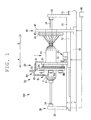
FIG. 1 is a side view of an FW apparatus according to a first embodiment illustrating a state where a hoop winding device is at a winding start position. -
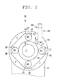
FIG. 2 is a view of the hoop winding device seen from a front direction of a liner in the state ofFIG. 1 . -
FIG. 3A is a front view of a chuck device; andFIG. 3B is a side view of the chuck device. -
FIG. 4 is a front view illustrating an opening state of the chuck device. -
FIG. 5 is a front view illustrating a closing state of the chuck device. -
FIG. 6 is a front view illustrating a state where a tension is applied on fiber bundles in the opening state of the chuck device. -
FIG. 7 is a side view of the FW apparatus illustrating a state where the hoop winding device starts winding. -
FIG. 8 is a view of the hoop winding device seen from a front direction of the liner in the state ofFIG. 7 . -
FIG. 9 is a side view of the FW apparatus illustrating a state where the hoop winding device is carrying out hoop winding -
FIG. 10 is a view of the hoop winding device seen from the front direction of the liner in the state ofFIG. 9 . -
FIG. 11 is a side view of the FW apparatus illustrating a state where the hoop winding device ends winding of the fiber bundles and the chuck device is holding the fiber bundles. -
FIG. 12 is a view of the hoop winding device seen from the front direction of the liner under a state ofFIG. 11 . -
FIG. 13 is a view of the hoop winding device seen from an axial direction of the liner in the a state where the fiber bundles are cut by a cutter. -
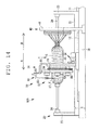
FIG. 14 is a side view of the FW apparatus illustrating a state where the hoop winding device ends the hoop winding and the chuck device is holding the fiber bundles. -
FIG. 15 is a view of the hoop winding device seen from the front direction of the liner in the a state ofFIG. 14 . -
FIG. 16 is a side view of the FW apparatus illustrating a state where the hoop winding device is moved to a standby position. - A
chuck device 51 and ahoop winding device 30 according to an embodiment of the present invention will be described with reference to the following drawings. First, an overall configuration of a filament winding apparatus (FW apparatus) 100 will be described with reference toFIG. 1 . TheFW apparatus 100 is adapted to wind a fiber bundle F impregnated with resin around aliner 1 by repeatedly carrying out hoop winding by thehoop winding device 30 and helical winding by the helical windingdevice 40 alternately with respect to theliner 1. - Arrows A, B illustrated in
FIG. 1 indicate a front-back direction of theFW apparatus 100 and a transfer direction of theliner 1 in the helical winding. In the helical winding, theliner 1 reciprocates in the front-back direction of theFW apparatus 100, and hence theliner 1 may be transferred in the direction of the arrow A or may be transferred in the direction of the arrow B. In the following description, a leading-end side of the arrow A and a base-end side of the arrow A respectively indicate a front side and a back side for convenience sake. - The
liner 1 is a base material that constitutes a pressure resistant container. Theliner 1 is a substantially cylindrical hollow body made of a high-strength aluminum material, polyamide resin, or the like, for example. A pressure resistance property of theliner 1 is improved by winding a plurality of fiber bundles F around an outercircumferential surface 1S of theliner 1 and thereby a plurality of fiber layers are formed. In the following description, theliner 1 refers to both a state before winding the fiber bundles F and a state in the middle of winding the fiber bundles F. For example, the outercircumferential surface 1S of theliner 1 also refers to a surface of the wound fiber bundles F. - As illustrated in
FIG. 1 , theFW apparatus 100 includes amain base 10, aliner transfer device 20, ahoop winding device 30, a helical windingdevice 40 and acontrol section 90. - The
main base 10 configures a base of theFW apparatus 100. Arail 11 for the liner transfer device is arranged at an upper part of themain base 10. Theliner transfer device 20 is mounted on therail 11 for the liner transfer device. Arail 12 for thehoop winding device 30 is arranged parallel to therail 11 for the liner transfer device at the upper part of themain base 10. Thehoop winding device 30 is mounted on therail 12 for the hoop winding device. Theliner transfer device 20 and thehoop winding device 30 are capable of moving with respect to themain base 10 in the front-back direction. The helical windingdevice 40 is fixed to themain base 10. - The
liner transfer device 20 is a device adapted to transfer theliner 1 while rotating theliner 1. Theliner transfer device 20 rotates theliner 1 with the front-back direction of theFW apparatus 100 as a center axis. In addition, theliner transfer device 20 transfers theliner 1 in the front-back direction of theFW apparatus 100. Theliner transfer device 20 includes afirst base 21, aliner supporting frame 23 and arotating shaft 24. Driving of theliner transfer device 20 is controlled by thecontrol section 90. - A pair of the
liner supporting frames 23 is arranged at an upper part of thefirst base 21. The rotatingshaft 24 extends from theliner supporting frame 23 in the front-back direction. Theliner 1 is mounted to therotating shaft 24 and is rotated in one direction by a power mechanism (not illustrated). - The
hoop winding device 30 forms a fiber layer by simultaneously winding a plurality of fiber bundles F around the outercircumferential surface 1S of theliner 1. Thehoop winding device 30 performs the hoop winding such that a winding angle of the fiber bundle F is substantially perpendicular with respect to the front-back direction of theFW apparatus 100. Thehoop winding device 30 includes asecond base 31, apower mechanism 32, ahoop winding head 34 and ahandling device 50. Driving of thehoop winding device 30 is controlled by thecontrol section 90. - The
hoop winding head 34 adapted to be rotated by thepower mechanism 32 is arranged in thesecond base 31. Thehoop winding head 34 includes anopening 35 where theliner 1 passes through a center thereof. A plurality of (four in the present embodiment) bobbins BA, BB, BC and BD are arranged around the opening 35 (seeFIG. 2 ). The fiber bundle F is supplied from each of the bobbins BA, BB, BC and BD to an outercircumferential surface 1S of theliner 1. Thepower mechanism 32 rotates thehoop winding head 34 about a center axis of theliner 1. - In the hoop winding, the
liner 1 is under a resting state without moving in an axial direction thereof or rotating. Thehoop winding head 34 is rotated about the center axis of theliner 1 while causing thehoop winding device 30 to reciprocate along a center axis direction of theliner 1. In other words, thehoop winding device 30 simultaneously winds the plurality of fiber bundles F around theliner 1 by relatively rotating thehoop winding head 34 with respect to theliner 1. Thehoop winding device 30 is capable of changing a winding mode of the fiber bundles F by adjusting a movement speed with respect to theliner 1 and a rotation speed of thehoop winding head 34. The handlingdevice 50 will be described later in detail. - The helical winding
device 40 forms a fiber layer by simultaneously winding the plurality of fiber bundles F around the outercircumferential surface 1S of theliner 1. The helical windingdevice 40 performs the helical winding such that a winding angle of the fiber bundles F is a predetermined value (for example, 0 to 60 degrees) with respect to the front-back direction of theFW apparatus 100. The helical windingdevice 40 includes athird base 41, a first helical windinghead 43 and a second helical windinghead 44. Driving the helical windingdevice 40 is controlled by thecontrol section 90. - The
third base 41 includes the first helical windinghead 43 and the second helical windinghead 44. The fiber bundles F are supplied from a plurality of bobbins (not illustrated) to the first helical windinghead 43 and the second helical windinghead 44. The plurality of fiber bundles F are guided to the outercircumferential surface 1S of theliner 1. A plurality of nozzles (not illustrated) are arranged towards the outercircumferential surface 1S of theliner 1 in each of the first helical windinghead 43 and the second helical windinghead 44 in a radial manner. The plurality of fiber bundles F are guided to the outercircumferential surface 1S of theliner 1 by the plurality of nozzles. The helical windingdevice 40 is fixed, and the helical winding is carried out with theliner 1 being transferred by theliner transfer device 20 while being rotated. The winding mode of the fiber bundles F can be freely changed by adjusting a transfer speed and a rotation speed of theliner 1. - Next, the
hoop winding device 30 and thehandling device 50, which are characteristic portions of the present invention, will be described in detail. As illustrated inFIG. 2 , thehoop winding head 34 of thehoop winding device 30 includes the bobbins BA, BB, BC and BD, afiber supply guide 37 and guiderollers 38. The bobbins BA, BB, BC and BD are arranged at equal intervals around theopening 35 of thehoop winding head 34. Theguide rollers 38 gather four fiber bundles F from the bobbins BA, BB, BC and BD and guide the same to thefiber supply guide 37. Thefiber supply guide 37 supplies the four fiber bundles F gathered by theguide rollers 38 to the outercircumferential surface 1S of theliner 1. - The
power mechanism 32 adapted to drive thehoop winding head 34 rotates thehoop winding head 34 in a direction of an arrow R inFIG. 8 . Since thehoop winding head 34 is rotated, the fiber bundles F supplied from thefiber supply guide 37 are wound around the outercircumferential surface 1S of theliner 1. The fiber bundle F is supplied in a direction of an arrow FA that is a downstream side in a rotation direction of thehoop winding head 34. A direction FA in which the fiber bundles F are supplied is hereinafter referred to as a fiber supply direction FA. A base-end side of the arrow FA is an upstream side in the fiber supply direction FA, and a leading-end side of the arrow FA is a downstream side in the fiber supply direction FA. A position where the fiber bundles F guided from thefiber supply guide 37 to theliner 1 make contact with the outercircumferential surface 1S of theliner 1, and then the fiber bundles F are wound around the outercircumferential surface 1S, is referred to as a winding position WP. - The
power mechanism 32 is connected to thecontrol section 90, and rotation and stop of thehoop winding head 34 are controlled based on a signal from thecontrol section 90. A detecting section (not illustrated) adapted to detect a rotation angle of thehoop winding head 34 and then to detect a position of thehoop winding head 34 is connected to thecontrol section 90. An encoder, for example, is employed as the detecting section. Thecontrol section 90 is capable of specifying positions of the bobbins BA, BB, BC and BD, the winding position WP of the fiber bundles F, or the like by detecting the position of thehoop winding head 34. Thecontrol section 90 is also capable of stopping the rotation of thehoop winding head 34 by controlling thepower mechanism 32 while detecting the position of thehoop winding head 34 such that thefiber supply guide 37 and the winding position WP of the fiber bundles F come to an arbitrary position. - Next, the handling
device 50 will be described. As illustrated inFIG. 1 ,FIG. 2 andFIG. 3 , the handlingdevice 50 includes achuck device 51 and anarm 80. At the start and at the end of the hoop winding, thechuck device 51 holds the fiber bundles F supplied from thefiber supply guide 37 of thehoop winding head 34. Thearm 80 supports thechuck device 51 in a same side of the bobbins BA, BB, BC and BD and afiber supply guide 37 of thehoop winding head 34. - As illustrated in
FIG. 3 , thechuck device 51 includes ahand 60 and adriving section 70. Thehand 60 includes afirst hand 61 and asecond hand 62. Thefirst hand 61 and thesecond hand 62 are switched by the drivingsection 70 between an opening state (seeFIG. 4 ) and a closing state (seeFIG. 5 ). Each of thefirst hand 61 and thesecond hand 62 includes a plurality ofguides 63. The plurality ofguides 63 are engaged with each other in the closing state and are released from each other in the opening state. - The driving
section 70 opens/closes thefirst hand 61 and thesecond hand 62. Afirst lever 71 is connected to thefirst hand 61, and asecond lever 72 is connected to thesecond hand 62. Thefirst lever 71 and thesecond lever 72 are supported by apin 75 in a freely rotating manner. Anactuator 76 includes ashaft 77 adapted to move forward and backward. Thefirst lever 71 is connected to theshaft 77 via athird lever 73. Thesecond lever 72 is connected to theshaft 77 via afourth lever 74. Since theshaft 77 of theactuator 76 moves forward and backward, thefirst lever 71 and thesecond lever 72 are opened/closed, and thereby thefirst hand 61 and thesecond hand 62 are switched between the opening state and the closing state. Driving of theactuator 76 is controlled by thecontrol section 90. By theactuator 76 being driven based on a signal from thecontrol section 90, thefirst hand 61 and thesecond hand 62 are opened/closed. - Each of the plurality of
guides 63 arranged in thefirst hand 61 and thesecond hand 62 is a plate-shaped body. Some of the plurality ofguides 63 are fixed to thefirst hand 61 by a first supportingbody 64. The other of the plurality ofguides 63 are fixed to thesecond hand 62 by a second supportingbody 65. A material, which is elastically deformed when external force is applied thereto, is employed for the plurality ofguides 63, the first supportingbody 64 and the second supportingbody 65. Stainless steel (SUS) is preferable, for example.Spacers 66 adapted to define intervals are arranged between theguides 63. The intervals betweenguides 63 are set slightly wider than a thickness of theguides 63 such that theguides 63 can engage with each other in the closing state. Each of thefirst hand 61 and thesecond hand 62 includes apad 67 adapted to hold the fiber bundle F by friction. - As illustrated in
FIG. 4 , in a case of the opening state, the plurality ofguides 63 of thefirst hand 61 and thesecond hand 62 are in a state where the engagement is released. In this state, the fiber bundles F can be inserted between thefirst hand 61 and thesecond hand 62. -
FIG. 5 illustrates the closing state, which is a state where the fiber bundles F are inserted between thefirst hand 61 and thesecond hand 62. The plurality ofguides 63 of thefirst hand 61 and thesecond hand 62 comes into a state of regulating and bending the fiber bundles F. Under the state illustrated inFIG. 5 , since tension of the fiber bundles F is low, the plurality ofguides 63, the first supportingbody 64 and the second supportingbody 65 are not elastically deformed. - As illustrated in
FIG. 6 , when tension in a direction of an arrow T is applied on the fiber bundles F under the state ofFIG. 5 , the plurality ofguides 63, the first supportingbody 64 and the second supportingbody 65 are elastically deformed. By the elastic deformation of the plurality ofguides 63, the first supportingbody 64 and the second supportingbody 65, theguides 63 are close to each other to hold the fiber bundle F. Under a state where the tension is applied on the fiber bundles F, intervals between end portions of the plurality ofguides 63, in particular, are narrowed and thereby the fiber bundles F are sandwiched by theguides 63 arranged side by side on a path of the fiber bundles F. When the closing state inFIG. 6 is shifted to the opening state inFIG. 4 , the held fiber bundles F are released. - The
arm 80 includes afirst arm 81, asecond arm 82 and athird arm 83. Thefirst arm 81 is fixed to thesecond base 31. Thesecond arm 82 is connected to thefirst arm 81 via an actuator (not illustrated) . Thesecond arm 82 is configured to be capable of moving in the front-back direction with respect to thefirst arm 81. Thethird arm 83 is connected to thesecond arm 82 via an actuator (not illustrated). Thethird arm 83 is configured to be capable of moving in an upper-lower direction with respect to thesecond arm 82. Driving of thearm 80 is controlled by thecontrol section 90. Based on a signal from thecontrol section 90, the actuators of thearm 80 are driven and thereby a position of thechuck device 51 is changed. - The
arm 80 is capable of switching the position of thechuck device 51 to a first position PA, a second position PB and a third position PC. The first position PA is a position of thechuck device 51 mainly at the time of starting the hoop winding (seeFIG. 2 ). The second position PB is a position where the fiber bundles F are caught by thechuck device 51 at the time of ending the hoop winding (seeFIG. 12 ). The third position PC is a position of thechuck device 51 in the middle of the hoop winding and under a state where thehoop winding device 30 is retreated (seeFIG. 10 andFIG. 15 ). Thearm 80 is also capable of moving thechuck device 51 in the front-back direction. - The cutter 68 cuts the fiber bundles F supplied from the
fiber supply guide 37 of thehoop winding head 34. As illustrated inFIG. 13 , the cutter 68 is arranged in thethird arm 83. When cutting the fiber bundle F, the cutter 68 projects out with respect to thethird arm 83 to cut the fiber bundles F. When being under standby, the cutter 68 retreats to a position not being in contact with the fiber bundles F. - Next, operation of the handling
device 50 in the hoop winding of theFW apparatus 100 having the above-described configuration will be described. Theliner 1 is mounted to theliner transfer device 20, and the hoop winding is performed following the helical winding performed previously. Thereafter, the helical winding is performed again. Winding conditions of the hoop winding, that is, the winding conditions such as a movement speed of thehoop winding device 30, a rotation speed of thehoop winding head 34, the number of times thehoop winding device 30 is reciprocated, and moved distance of thehoop winding device 30, are input to thecontrol section 90 in advance by an operator. Thecontrol section 90 controls the driving of thehoop winding device 30 in the following manner based on the input winding conditions. - As illustrated in
FIG. 2 , a position (a position in a rotation direction) of when thehoop winding head 34 is stopped is set such that thechuck device 51 is positioned between the bobbin BA and the bobbin BD. The position of thehoop winding head 34 in the rotation direction will be hereinafter referred to as a processing stop position. - When the helical winding before the hoop winding is finished, as illustrated in
FIG. 1 , thehoop winding device 30 is moved along the front-back direction of theFW apparatus 100 from a standby position (seeFIG. 16 ) to move to a position to start the hoop winding. In the present embodiment, the hoop winding is started from one end of a tubular portion of theliner 1. When thehoop winding device 30 is moved, thehoop winding head 34 has a process suspension posture. Thechuck device 51 is at the third position PC (seeFIG. 15 ). Thechuck device 51 grips the fiber bundles F supplied from thefiber supply guide 37 of thehoop winding head 34. - As illustrated in
FIG. 1 andFIG. 2 , when thehoop winding device 30 reaches the position (a winding start position) to start the hoop winding, as illustrated inFIG. 7 andFIG. 8 , thechuck device 51 is moved to the first position PA. - The
hoop winding device 30 starts the winding of the fiber bundles F. For the first few windings, the tension of the fiber bundle F is set lower than a prescribed tension, and under this state, next fiber bundles F are wound so as to overlap the fiber bundles F wound underneath. Alternatively, the next fiber bundles F are wound so as to intersect the fiber bundles F wound underneath. At this time, if a position of thechuck device 51 in the front-back direction with respect to thehoop winding head 34 is fixed, thechuck device 51 interferes with the fiber bundles F or the rotatingfiber supply guide 37. Thus, thearm 80 is driven such that thechuck device 51 is gradually located away from thehoop winding head 34. At this time, a position of thechuck device 51 in the front-back direction with respect to theliner 1 is not changed. After winding the first few windings, the tension is set to the prescribed tension and the hoop winding is carried out. Thechuck device 51 is under the opening state, and the fiber bundles F are released. - As illustrated in
FIG. 9 andFIG. 10 , since thehoop winding device 30 moves in a right direction on a page ofFIG. 9 while rotating thehoop winding head 34, the fiber bundles F are hoop wound around the outercircumferential surface 1S of the tubular portion. A first hoop winding layer is formed under this state. Subsequently, thehoop winding device 30 is reversely moved to form a second hoop winding layer on an outer surface of the previous hoop winding layer. In a case of further forming a hoop winding layer, the hoop winding is carried out a required number of times by reciprocating thehoop winding device 30. - After the hoop winding of the required number of times is finished, as illustrated in
FIG. 11 andFIG. 12 , thehoop winding head 34 is stopped in the processing suspension posture. Thechuck device 51 moves from the first position PA towards the second position PB. Thechuck device 51 is brought close to the fiber bundles F supplied from thefiber supply guide 37 of thehoop winding head 34 with thechuck device 51 opened. When the fiber bundles F are caught between thefirst hand 61 and thesecond hand 62, thechuck device 51 is brought into the closing state to grip the fiber bundles F. A position where the fiber bundles F are gripped is between thefiber supply guide 37 and the winding position WP of the fiber bundles F. - As illustrated in
FIG. 13 , when the fiber bundles F are fixed to the fiber bundles F previously wound in the hoop winding, the cutter 68 projects out. The cutter 68 cuts the fiber bundles F downstream in the fiber supply direction FA of a position where thechuck device 51 holds the fiber bundle F. The hoop-wound fiber bundle F is thereby separated from the bobbins BA, BB, BC and BD at an ending position of the hoop winding. - When the cutter 68 cuts the fiber bundles F in
FIG. 14 andFIG. 15 , thechuck device 51 moves from the second position PB towards the third position PC as illustrated inFIG. 11 . Thechuck device 51 grips the fiber bundles F supplied from thefiber supply guide 37 of thehoop winding head 34. As illustrated inFIG. 16 , thehoop winding device 30 is moved along the front-back direction of theFW apparatus 100 from the ending position of the hoop winding to the standby position. Thechuck device 51 is under standby at this position until the next helical winding is finished. Then, if the hoop winding is to be again carried out, the next hoop winding is carried out from the state illustrated inFIG. 1 andFIG. 6 . - 1 The
chuck device 51 and thehoop winding device 30 according to the present embodiment described above have the following effects. - The plurality of
guides 63 of thechuck device 51 holds the fiber bundles F by being close to each other with the tension applied on the fiber bundles F under the closing state. Since the fiber bundles F are held by use of the tension applied on the fiber bundles F, in a case where the tension applied on the fiber bundles F is high, a force of holding the fiber bundles F is enhanced accordingly. The fiber bundle F thus can be firmly held. - The plurality of
guides 63 of thechuck device 51 are close to each other by the first supportingbody 64 and the second supportingbody 65 being elastically deformed with the tension applied on the fiber bundles F under the closing state. Thus, the force of holding the fiber bundle F can be enhanced according to the tension applied on the fiber bundle F. - The
hand 60 of thechuck device 51 includes thepad 67 adapted to hold the fiber bundles F by friction. The fiber bundles F thus can be further firmly held. - The embodiment of the present invention has been described above, but the present invention is not limited to the embodiments described above, and various modifications can be made. For example, a positional relationship between the
hoop winding head 34 and thehandling device 50 is not limited to a positional relationship illustrated inFIG. 1 and merely needs to be a positional relationship in which thehoop winding head 34 and thehandling device 50 do not interfere with each other and the fiber bundles F supplied from thefiber supply guide 37 of thehoop winding head 34 can be gripped. If structure or arrangement of thehoop winding head 34 and thehandling device 50 are different, the positional relationship is different. - While the present invention has been described with respect to preferred embodiments thereof, it will be apparent to those skilled in the art that the disclosed invention may be modified in numerous ways and may assume many embodiments other than those specifically set out and described above. Accordingly, it is intended by the appended claims to cover all modifications of the present invention that fall within the true spirit and scope of the present claims.
Claims (6)
- A chuck device (51) for a fiber bundle (F) comprising a pair of hands (61, 62) adapted to be opened/closed,
characterized in that the pair of hands (61, 62) includes a plurality of guides (63) adapted to regulate and bend the fiber bundle (F) under a closing state, and to release the fiber bundle (F) under an opening state, and
under the closing state, the plurality of guides (63) is adapted to hold the fiber bundle (F) by being close to each other with a tension applied on the fiber bundle (F). - The chuck device (51) according to claim 1, characterized in that the hand (61, 62) includes supporting bodies (64, 65) adapted to support the plurality of guides (63), and
under the closing state, the guides (63) are close to each other by the supporting bodies (64, 65) being elastically deformed with the tension applied on the fiber bundle (F). - The chuck device (51) according to claim 1 or claim 2, characterized in that the hand (61, 62) further includes a pad (67) adapted to hold the fiber bundle (F) by friction.
- A hoop winding device (30) comprising the chuck device (51) according to any one of claim 1 through claim 3, the hoop winding device (30) being adapted to rotate about a resting liner (1) around which the fiber bundle (F) is wound and to support in a freely rotating manner, a bobbin (BA, BB, BC and BD) around which the fiber bundle (F) is wound.
- The hoop winding device (30) according to claim 4, the hoop winding device (30) being capable of supporting a plurality of the bobbins (BA, BB, BC and BD),
characterized in that the chuck device (51) is adapted to simultaneously grip a plurality of fiber bundles (F) for hoop winding. - The hoop winding device (30) according to claim 4 or claim 5, characterized by a cutter (68) adapted to cut the fiber bundle (F) for the hoop winding gripped by the chuck device (51).
Applications Claiming Priority (1)
| Application Number | Priority Date | Filing Date | Title |
|---|---|---|---|
| JP2013023768A JP5902635B2 (en) | 2013-02-08 | 2013-02-08 | Chuck device and hoop winding device |
Publications (2)
| Publication Number | Publication Date |
|---|---|
| EP2765103A1 true EP2765103A1 (en) | 2014-08-13 |
| EP2765103B1 EP2765103B1 (en) | 2018-08-22 |
Family
ID=49958202
Family Applications (1)
| Application Number | Title | Priority Date | Filing Date |
|---|---|---|---|
| EP13199722.3A Active EP2765103B1 (en) | 2013-02-08 | 2013-12-27 | Chuck device and hoop winding device |
Country Status (5)
| Country | Link |
|---|---|
| US (1) | US9498916B2 (en) |
| EP (1) | EP2765103B1 (en) |
| JP (1) | JP5902635B2 (en) |
| KR (1) | KR101729606B1 (en) |
| CN (1) | CN103978672B (en) |
Cited By (1)
| Publication number | Priority date | Publication date | Assignee | Title |
|---|---|---|---|---|
| CN105563853A (en) * | 2016-01-26 | 2016-05-11 | 云浮市欣粤电力器材有限公司 | Fiber axial zero-degree laying and binding device for production of conical electric pole |
Families Citing this family (6)
| Publication number | Priority date | Publication date | Assignee | Title |
|---|---|---|---|---|
| US20140261847A1 (en) * | 2013-03-14 | 2014-09-18 | Sara Molina | Composite mandrel for an isolation tool |
| JP6881138B2 (en) * | 2017-08-07 | 2021-06-02 | 村田機械株式会社 | Filament winding device |
| KR102256960B1 (en) * | 2017-09-27 | 2021-05-27 | 무라다기카이가부시끼가이샤 | Filament winding device |
| KR102382340B1 (en) * | 2020-12-29 | 2022-04-04 | 주식회사 디쏠 | Elastic pressing type apparatus for winding of reinforced fiber |
| CN113371528B (en) * | 2021-06-07 | 2022-10-14 | 太原理工大学 | Multi-beam fiber hoop winding device and control system thereof |
| DE112024002368T5 (en) * | 2023-05-30 | 2026-03-19 | Murata Machinery, Ltd. | FILAMENT WINDING DEVICE |
Citations (3)
| Publication number | Priority date | Publication date | Assignee | Title |
|---|---|---|---|---|
| DE4335089A1 (en) * | 1992-10-16 | 1994-04-21 | Murata Machinery Ltd | Automatic control system for winding machines - designates one specific unit whose data is detected and controlled to operate all other units. |
| DE102007053466A1 (en) * | 2007-11-09 | 2009-05-14 | Oerlikon Textile Gmbh & Co. Kg | Thread e.g. yarn, tensioning device for use in spooling machine of textile industry, has delimitation element and tensioning arm adjustable to each other such that thread between delimitation element and guide element of arm is clampable |
| EP2407406A2 (en) * | 2010-07-14 | 2012-01-18 | Murata Machinery, Ltd. | Fluff binding device, tension applying unit, and automatic winder |
Family Cites Families (24)
| Publication number | Priority date | Publication date | Assignee | Title |
|---|---|---|---|---|
| NL269849A (en) * | 1960-10-05 | |||
| US3523300A (en) * | 1966-08-18 | 1970-08-04 | Toray Industries | Spinning method and apparatus for manufacturing yarn from textile fibers |
| US4010054A (en) * | 1971-05-03 | 1977-03-01 | Albert L. Jeffers | Thermoplastic filament winding process |
| US4112661A (en) * | 1977-04-15 | 1978-09-12 | Kabushiki Kaisha Toyoda Jidoshokki Seisakusho | Open-end spinning machine and a method of stopping the same |
| FR2585375B1 (en) * | 1985-07-25 | 1988-04-08 | Saint Gobain Vetrotex | DEVICE AND METHOD FOR SIMULTANEOUSLY WINDING SEPARATE THREADS ON A ROTATING MEDIUM |
| US4892764A (en) * | 1985-11-26 | 1990-01-09 | Loctite Corporation | Fiber/resin composites, and method of making the same |
| DE4005771C1 (en) * | 1990-02-23 | 1991-09-19 | Deutsche Forschungsanstalt Fuer Luft- Und Raumfahrt Ev, 5300 Bonn, De | Cpd. fibre coupling mfg. - uses tubular wound section flanked by conical wound sections to be compressed into flanges |
| JP2936948B2 (en) * | 1993-02-25 | 1999-08-23 | 村田機械株式会社 | Automatic winder tension controller |
| US7185778B1 (en) * | 1995-09-25 | 2007-03-06 | Allied-Signal Inc. | Barrier units and articles made therefrom |
| US6074595A (en) * | 1998-10-16 | 2000-06-13 | Codeline Corporation | Method of making pressure vessels |
| TW504526B (en) * | 1998-12-25 | 2002-10-01 | Murata Machinery Ltd | Hairiness suppressing device for automatic winder |
| FR2807967B1 (en) * | 2000-04-25 | 2003-01-17 | Lapeyre | JOINING ELEMENT FORMED FROM EXTRUDABLE ORGANIC MATERIAL REINFORCED BY REINFORCING FIBERS, METHOD AND DEVICE FOR MANUFACTURING |
| US20030000619A1 (en) * | 2000-04-28 | 2003-01-02 | Masaaki Nakamura | Rubber-reinforcing fiber, process for producing the same, and rubber product and pneumatic tire each made with the same |
| JP2003200503A (en) * | 2002-01-07 | 2003-07-15 | Toyota Industries Corp | Filament winding device |
| JP3885665B2 (en) * | 2002-06-03 | 2007-02-21 | 村田機械株式会社 | Automatic winder blackout system |
| US7255302B2 (en) * | 2004-03-10 | 2007-08-14 | Mitsubishi Rayon Co., Ltd. | Guide apparatus for continuous fiber bundle, winding machine for continuous fiber bundle equipped with the guide apparatus, method for making bobbin by the winding machine, and carbon fiber bobbin made by the method |
| JP4420251B2 (en) * | 2007-09-12 | 2010-02-24 | 村田機械株式会社 | Filament winding equipment |
| JP5578304B2 (en) * | 2008-06-20 | 2014-08-27 | 村田機械株式会社 | Fiber bundle tension management system and filament bundle tension management method in filament winding apparatus |
| JP5206949B2 (en) * | 2008-06-20 | 2013-06-12 | 村田機械株式会社 | Filament winding apparatus and method |
| JP5256919B2 (en) * | 2008-08-05 | 2013-08-07 | 村田機械株式会社 | Filament winding equipment |
| JP2011251446A (en) * | 2010-06-01 | 2011-12-15 | Teijin Ltd | Continuous fiber composite material structure, method for manufacturing the same, and composite molded object using the continuous fiber composite material structure |
| CN102152474A (en) * | 2010-11-12 | 2011-08-17 | 天津工业大学 | Control method of filament winding constant tension of no-gyrating bodycomposite material member |
| US8955787B2 (en) * | 2010-11-16 | 2015-02-17 | Murata Machinery, Ltd. | Filament winding apparatus |
| WO2014039482A1 (en) * | 2012-09-07 | 2014-03-13 | General Plastics & Composites, L.P. | Method and apparatus for resin film infusion |
-
2013
- 2013-02-08 JP JP2013023768A patent/JP5902635B2/en active Active
- 2013-12-09 KR KR1020130152586A patent/KR101729606B1/en active Active
- 2013-12-17 CN CN201310692666.3A patent/CN103978672B/en active Active
- 2013-12-27 EP EP13199722.3A patent/EP2765103B1/en active Active
-
2014
- 2014-01-21 US US14/160,025 patent/US9498916B2/en active Active
Patent Citations (3)
| Publication number | Priority date | Publication date | Assignee | Title |
|---|---|---|---|---|
| DE4335089A1 (en) * | 1992-10-16 | 1994-04-21 | Murata Machinery Ltd | Automatic control system for winding machines - designates one specific unit whose data is detected and controlled to operate all other units. |
| DE102007053466A1 (en) * | 2007-11-09 | 2009-05-14 | Oerlikon Textile Gmbh & Co. Kg | Thread e.g. yarn, tensioning device for use in spooling machine of textile industry, has delimitation element and tensioning arm adjustable to each other such that thread between delimitation element and guide element of arm is clampable |
| EP2407406A2 (en) * | 2010-07-14 | 2012-01-18 | Murata Machinery, Ltd. | Fluff binding device, tension applying unit, and automatic winder |
Cited By (1)
| Publication number | Priority date | Publication date | Assignee | Title |
|---|---|---|---|---|
| CN105563853A (en) * | 2016-01-26 | 2016-05-11 | 云浮市欣粤电力器材有限公司 | Fiber axial zero-degree laying and binding device for production of conical electric pole |
Also Published As
| Publication number | Publication date |
|---|---|
| JP5902635B2 (en) | 2016-04-13 |
| KR20140101277A (en) | 2014-08-19 |
| CN103978672B (en) | 2018-10-26 |
| JP2014151568A (en) | 2014-08-25 |
| US9498916B2 (en) | 2016-11-22 |
| CN103978672A (en) | 2014-08-13 |
| EP2765103B1 (en) | 2018-08-22 |
| KR101729606B1 (en) | 2017-04-24 |
| US20140224918A1 (en) | 2014-08-14 |
Similar Documents
| Publication | Publication Date | Title |
|---|---|---|
| EP2765103B1 (en) | Chuck device and hoop winding device | |
| US9156202B2 (en) | Filament winding method and filament winding apparatus | |
| JP4420250B2 (en) | Filament winding equipment | |
| CN101378212B (en) | Winding device | |
| US8267343B2 (en) | Winding machine and method for controlling a winding machine | |
| EP2615051B1 (en) | Wire bundling device and wire bundling method | |
| EP2682961B1 (en) | Wire winding apparatus and wire winding method | |
| EP2036698A2 (en) | Filament winding apparatus | |
| US20150053808A1 (en) | Filament Winding Apparatus | |
| CN105960368A (en) | Device and method for transferring advancing yarn during bobbin changeover of an automatic turret yarn winder | |
| JP2012035290A (en) | Straightening device of wire material | |
| JP5220936B1 (en) | Traverse equipment | |
| US11008192B2 (en) | Fiber bundle joining apparatus and fiber bundle joining method | |
| JP2018130839A (en) | Roving tension imparting mechanism in filament winding apparatus | |
| JP2004148776A (en) | Filament winding device | |
| EP2994404B1 (en) | Machine for winding of pre-stretched film reels. | |
| US8955788B2 (en) | Filament winding apparatus | |
| JP2017164873A (en) | Wire processing system and wire processing method | |
| RU2662539C1 (en) | Deforming device for steel wire intended for tire bead cores | |
| KR20150030221A (en) | Device for winding bead ring-binding thread | |
| JPS60143935A (en) | Wind-up machine for forming cylindrical structure by windingup synthetic substance reinforced by fiber | |
| JP5930723B2 (en) | V belt transfer device | |
| JP2018130841A (en) | Roving installation mechanism to liner in filament winding device | |
| CN121175178A (en) | Filament winding device |
Legal Events
| Date | Code | Title | Description |
|---|---|---|---|
| PUAI | Public reference made under article 153(3) epc to a published international application that has entered the european phase |
Free format text: ORIGINAL CODE: 0009012 |
|
| 17P | Request for examination filed |
Effective date: 20131227 |
|
| AK | Designated contracting states |
Kind code of ref document: A1 Designated state(s): AL AT BE BG CH CY CZ DE DK EE ES FI FR GB GR HR HU IE IS IT LI LT LU LV MC MK MT NL NO PL PT RO RS SE SI SK SM TR |
|
| AX | Request for extension of the european patent |
Extension state: BA ME |
|
| R17P | Request for examination filed (corrected) |
Effective date: 20140717 |
|
| RBV | Designated contracting states (corrected) |
Designated state(s): AL AT BE BG CH CY CZ DE DK EE ES FI FR GB GR HR HU IE IS IT LI LT LU LV MC MK MT NL NO PL PT RO RS SE SI SK SM TR |
|
| 17Q | First examination report despatched |
Effective date: 20171020 |
|
| GRAP | Despatch of communication of intention to grant a patent |
Free format text: ORIGINAL CODE: EPIDOSNIGR1 |
|
| RIC1 | Information provided on ipc code assigned before grant |
Ipc: B29C 53/80 20060101ALN20180423BHEP Ipc: B65H 59/28 20060101AFI20180423BHEP |
|
| INTG | Intention to grant announced |
Effective date: 20180517 |
|
| GRAS | Grant fee paid |
Free format text: ORIGINAL CODE: EPIDOSNIGR3 |
|
| GRAA | (expected) grant |
Free format text: ORIGINAL CODE: 0009210 |
|
| AK | Designated contracting states |
Kind code of ref document: B1 Designated state(s): AL AT BE BG CH CY CZ DE DK EE ES FI FR GB GR HR HU IE IS IT LI LT LU LV MC MK MT NL NO PL PT RO RS SE SI SK SM TR |
|
| REG | Reference to a national code |
Ref country code: GB Ref legal event code: FG4D |
|
| REG | Reference to a national code |
Ref country code: CH Ref legal event code: EP |
|
| REG | Reference to a national code |
Ref country code: AT Ref legal event code: REF Ref document number: 1032215 Country of ref document: AT Kind code of ref document: T Effective date: 20180915 |
|
| REG | Reference to a national code |
Ref country code: IE Ref legal event code: FG4D |
|
| REG | Reference to a national code |
Ref country code: DE Ref legal event code: R096 Ref document number: 602013042321 Country of ref document: DE |
|
| REG | Reference to a national code |
Ref country code: NL Ref legal event code: MP Effective date: 20180822 |
|
| REG | Reference to a national code |
Ref country code: LT Ref legal event code: MG4D |
|
| PG25 | Lapsed in a contracting state [announced via postgrant information from national office to epo] |
Ref country code: GR Free format text: LAPSE BECAUSE OF FAILURE TO SUBMIT A TRANSLATION OF THE DESCRIPTION OR TO PAY THE FEE WITHIN THE PRESCRIBED TIME-LIMIT Effective date: 20181123 Ref country code: BG Free format text: LAPSE BECAUSE OF FAILURE TO SUBMIT A TRANSLATION OF THE DESCRIPTION OR TO PAY THE FEE WITHIN THE PRESCRIBED TIME-LIMIT Effective date: 20181122 Ref country code: NL Free format text: LAPSE BECAUSE OF FAILURE TO SUBMIT A TRANSLATION OF THE DESCRIPTION OR TO PAY THE FEE WITHIN THE PRESCRIBED TIME-LIMIT Effective date: 20180822 Ref country code: NO Free format text: LAPSE BECAUSE OF FAILURE TO SUBMIT A TRANSLATION OF THE DESCRIPTION OR TO PAY THE FEE WITHIN THE PRESCRIBED TIME-LIMIT Effective date: 20181122 Ref country code: IS Free format text: LAPSE BECAUSE OF FAILURE TO SUBMIT A TRANSLATION OF THE DESCRIPTION OR TO PAY THE FEE WITHIN THE PRESCRIBED TIME-LIMIT Effective date: 20181222 Ref country code: RS Free format text: LAPSE BECAUSE OF FAILURE TO SUBMIT A TRANSLATION OF THE DESCRIPTION OR TO PAY THE FEE WITHIN THE PRESCRIBED TIME-LIMIT Effective date: 20180822 Ref country code: LT Free format text: LAPSE BECAUSE OF FAILURE TO SUBMIT A TRANSLATION OF THE DESCRIPTION OR TO PAY THE FEE WITHIN THE PRESCRIBED TIME-LIMIT Effective date: 20180822 Ref country code: FI Free format text: LAPSE BECAUSE OF FAILURE TO SUBMIT A TRANSLATION OF THE DESCRIPTION OR TO PAY THE FEE WITHIN THE PRESCRIBED TIME-LIMIT Effective date: 20180822 Ref country code: SE Free format text: LAPSE BECAUSE OF FAILURE TO SUBMIT A TRANSLATION OF THE DESCRIPTION OR TO PAY THE FEE WITHIN THE PRESCRIBED TIME-LIMIT Effective date: 20180822 |
|
| REG | Reference to a national code |
Ref country code: AT Ref legal event code: MK05 Ref document number: 1032215 Country of ref document: AT Kind code of ref document: T Effective date: 20180822 |
|
| PG25 | Lapsed in a contracting state [announced via postgrant information from national office to epo] |
Ref country code: AL Free format text: LAPSE BECAUSE OF FAILURE TO SUBMIT A TRANSLATION OF THE DESCRIPTION OR TO PAY THE FEE WITHIN THE PRESCRIBED TIME-LIMIT Effective date: 20180822 Ref country code: LV Free format text: LAPSE BECAUSE OF FAILURE TO SUBMIT A TRANSLATION OF THE DESCRIPTION OR TO PAY THE FEE WITHIN THE PRESCRIBED TIME-LIMIT Effective date: 20180822 Ref country code: HR Free format text: LAPSE BECAUSE OF FAILURE TO SUBMIT A TRANSLATION OF THE DESCRIPTION OR TO PAY THE FEE WITHIN THE PRESCRIBED TIME-LIMIT Effective date: 20180822 |
|
| PG25 | Lapsed in a contracting state [announced via postgrant information from national office to epo] |
Ref country code: EE Free format text: LAPSE BECAUSE OF FAILURE TO SUBMIT A TRANSLATION OF THE DESCRIPTION OR TO PAY THE FEE WITHIN THE PRESCRIBED TIME-LIMIT Effective date: 20180822 Ref country code: AT Free format text: LAPSE BECAUSE OF FAILURE TO SUBMIT A TRANSLATION OF THE DESCRIPTION OR TO PAY THE FEE WITHIN THE PRESCRIBED TIME-LIMIT Effective date: 20180822 Ref country code: PL Free format text: LAPSE BECAUSE OF FAILURE TO SUBMIT A TRANSLATION OF THE DESCRIPTION OR TO PAY THE FEE WITHIN THE PRESCRIBED TIME-LIMIT Effective date: 20180822 Ref country code: CZ Free format text: LAPSE BECAUSE OF FAILURE TO SUBMIT A TRANSLATION OF THE DESCRIPTION OR TO PAY THE FEE WITHIN THE PRESCRIBED TIME-LIMIT Effective date: 20180822 Ref country code: IT Free format text: LAPSE BECAUSE OF FAILURE TO SUBMIT A TRANSLATION OF THE DESCRIPTION OR TO PAY THE FEE WITHIN THE PRESCRIBED TIME-LIMIT Effective date: 20180822 Ref country code: ES Free format text: LAPSE BECAUSE OF FAILURE TO SUBMIT A TRANSLATION OF THE DESCRIPTION OR TO PAY THE FEE WITHIN THE PRESCRIBED TIME-LIMIT Effective date: 20180822 Ref country code: RO Free format text: LAPSE BECAUSE OF FAILURE TO SUBMIT A TRANSLATION OF THE DESCRIPTION OR TO PAY THE FEE WITHIN THE PRESCRIBED TIME-LIMIT Effective date: 20180822 |
|
| REG | Reference to a national code |
Ref country code: DE Ref legal event code: R097 Ref document number: 602013042321 Country of ref document: DE |
|
| PG25 | Lapsed in a contracting state [announced via postgrant information from national office to epo] |
Ref country code: DK Free format text: LAPSE BECAUSE OF FAILURE TO SUBMIT A TRANSLATION OF THE DESCRIPTION OR TO PAY THE FEE WITHIN THE PRESCRIBED TIME-LIMIT Effective date: 20180822 Ref country code: SM Free format text: LAPSE BECAUSE OF FAILURE TO SUBMIT A TRANSLATION OF THE DESCRIPTION OR TO PAY THE FEE WITHIN THE PRESCRIBED TIME-LIMIT Effective date: 20180822 Ref country code: SK Free format text: LAPSE BECAUSE OF FAILURE TO SUBMIT A TRANSLATION OF THE DESCRIPTION OR TO PAY THE FEE WITHIN THE PRESCRIBED TIME-LIMIT Effective date: 20180822 |
|
| PLBE | No opposition filed within time limit |
Free format text: ORIGINAL CODE: 0009261 |
|
| STAA | Information on the status of an ep patent application or granted ep patent |
Free format text: STATUS: NO OPPOSITION FILED WITHIN TIME LIMIT |
|
| 26N | No opposition filed |
Effective date: 20190523 |
|
| REG | Reference to a national code |
Ref country code: CH Ref legal event code: PL |
|
| GBPC | Gb: european patent ceased through non-payment of renewal fee |
Effective date: 20181227 |
|
| PG25 | Lapsed in a contracting state [announced via postgrant information from national office to epo] |
Ref country code: SI Free format text: LAPSE BECAUSE OF FAILURE TO SUBMIT A TRANSLATION OF THE DESCRIPTION OR TO PAY THE FEE WITHIN THE PRESCRIBED TIME-LIMIT Effective date: 20180822 Ref country code: MC Free format text: LAPSE BECAUSE OF FAILURE TO SUBMIT A TRANSLATION OF THE DESCRIPTION OR TO PAY THE FEE WITHIN THE PRESCRIBED TIME-LIMIT Effective date: 20180822 Ref country code: LU Free format text: LAPSE BECAUSE OF NON-PAYMENT OF DUE FEES Effective date: 20181227 |
|
| REG | Reference to a national code |
Ref country code: IE Ref legal event code: MM4A |
|
| REG | Reference to a national code |
Ref country code: BE Ref legal event code: MM Effective date: 20181231 |
|
| PG25 | Lapsed in a contracting state [announced via postgrant information from national office to epo] |
Ref country code: FR Free format text: LAPSE BECAUSE OF NON-PAYMENT OF DUE FEES Effective date: 20181231 Ref country code: IE Free format text: LAPSE BECAUSE OF NON-PAYMENT OF DUE FEES Effective date: 20181227 |
|
| PG25 | Lapsed in a contracting state [announced via postgrant information from national office to epo] |
Ref country code: BE Free format text: LAPSE BECAUSE OF NON-PAYMENT OF DUE FEES Effective date: 20181231 |
|
| PG25 | Lapsed in a contracting state [announced via postgrant information from national office to epo] |
Ref country code: CH Free format text: LAPSE BECAUSE OF NON-PAYMENT OF DUE FEES Effective date: 20181231 Ref country code: LI Free format text: LAPSE BECAUSE OF NON-PAYMENT OF DUE FEES Effective date: 20181231 Ref country code: GB Free format text: LAPSE BECAUSE OF NON-PAYMENT OF DUE FEES Effective date: 20181227 |
|
| PG25 | Lapsed in a contracting state [announced via postgrant information from national office to epo] |
Ref country code: MT Free format text: LAPSE BECAUSE OF NON-PAYMENT OF DUE FEES Effective date: 20181227 |
|
| PG25 | Lapsed in a contracting state [announced via postgrant information from national office to epo] |
Ref country code: TR Free format text: LAPSE BECAUSE OF FAILURE TO SUBMIT A TRANSLATION OF THE DESCRIPTION OR TO PAY THE FEE WITHIN THE PRESCRIBED TIME-LIMIT Effective date: 20180822 |
|
| PG25 | Lapsed in a contracting state [announced via postgrant information from national office to epo] |
Ref country code: PT Free format text: LAPSE BECAUSE OF FAILURE TO SUBMIT A TRANSLATION OF THE DESCRIPTION OR TO PAY THE FEE WITHIN THE PRESCRIBED TIME-LIMIT Effective date: 20180822 |
|
| PG25 | Lapsed in a contracting state [announced via postgrant information from national office to epo] |
Ref country code: HU Free format text: LAPSE BECAUSE OF FAILURE TO SUBMIT A TRANSLATION OF THE DESCRIPTION OR TO PAY THE FEE WITHIN THE PRESCRIBED TIME-LIMIT; INVALID AB INITIO Effective date: 20131227 Ref country code: CY Free format text: LAPSE BECAUSE OF FAILURE TO SUBMIT A TRANSLATION OF THE DESCRIPTION OR TO PAY THE FEE WITHIN THE PRESCRIBED TIME-LIMIT Effective date: 20180822 Ref country code: MK Free format text: LAPSE BECAUSE OF NON-PAYMENT OF DUE FEES Effective date: 20180822 |
|
| PGFP | Annual fee paid to national office [announced via postgrant information from national office to epo] |
Ref country code: DE Payment date: 20251126 Year of fee payment: 13 |