EP2765042A2 - Compressed air supply apparatus - Google Patents
Compressed air supply apparatus Download PDFInfo
- Publication number
- EP2765042A2 EP2765042A2 EP13194169.2A EP13194169A EP2765042A2 EP 2765042 A2 EP2765042 A2 EP 2765042A2 EP 13194169 A EP13194169 A EP 13194169A EP 2765042 A2 EP2765042 A2 EP 2765042A2
- Authority
- EP
- European Patent Office
- Prior art keywords
- pressure
- air
- flow path
- compressed air
- air compressor
- Prior art date
- Legal status (The legal status is an assumption and is not a legal conclusion. Google has not performed a legal analysis and makes no representation as to the accuracy of the status listed.)
- Granted
Links
Images




Classifications
-
- F—MECHANICAL ENGINEERING; LIGHTING; HEATING; WEAPONS; BLASTING
- F04—POSITIVE - DISPLACEMENT MACHINES FOR LIQUIDS; PUMPS FOR LIQUIDS OR ELASTIC FLUIDS
- F04B—POSITIVE-DISPLACEMENT MACHINES FOR LIQUIDS; PUMPS
- F04B41/00—Pumping installations or systems specially adapted for elastic fluids
- F04B41/02—Pumping installations or systems specially adapted for elastic fluids having reservoirs
-
- B—PERFORMING OPERATIONS; TRANSPORTING
- B60—VEHICLES IN GENERAL
- B60T—VEHICLE BRAKE CONTROL SYSTEMS OR PARTS THEREOF; BRAKE CONTROL SYSTEMS OR PARTS THEREOF, IN GENERAL; ARRANGEMENT OF BRAKING ELEMENTS ON VEHICLES IN GENERAL; PORTABLE DEVICES FOR PREVENTING UNWANTED MOVEMENT OF VEHICLES; VEHICLE MODIFICATIONS TO FACILITATE COOLING OF BRAKES
- B60T13/00—Transmitting braking action from initiating means to ultimate brake actuator with power assistance or drive; Brake systems incorporating such transmitting means, e.g. air-pressure brake systems
- B60T13/10—Transmitting braking action from initiating means to ultimate brake actuator with power assistance or drive; Brake systems incorporating such transmitting means, e.g. air-pressure brake systems with fluid assistance, drive, or release
- B60T13/66—Electrical control in fluid-pressure brake systems
- B60T13/665—Electrical control in fluid-pressure brake systems the systems being specially adapted for transferring two or more command signals, e.g. railway systems
-
- B—PERFORMING OPERATIONS; TRANSPORTING
- B60—VEHICLES IN GENERAL
- B60T—VEHICLE BRAKE CONTROL SYSTEMS OR PARTS THEREOF; BRAKE CONTROL SYSTEMS OR PARTS THEREOF, IN GENERAL; ARRANGEMENT OF BRAKING ELEMENTS ON VEHICLES IN GENERAL; PORTABLE DEVICES FOR PREVENTING UNWANTED MOVEMENT OF VEHICLES; VEHICLE MODIFICATIONS TO FACILITATE COOLING OF BRAKES
- B60T17/00—Component parts, details, or accessories of power brake systems not covered by groups B60T8/00, B60T13/00 or B60T15/00, or presenting other characteristic features
- B60T17/02—Arrangements of pumps or compressors, or control devices therefor
-
- B—PERFORMING OPERATIONS; TRANSPORTING
- B60—VEHICLES IN GENERAL
- B60T—VEHICLE BRAKE CONTROL SYSTEMS OR PARTS THEREOF; BRAKE CONTROL SYSTEMS OR PARTS THEREOF, IN GENERAL; ARRANGEMENT OF BRAKING ELEMENTS ON VEHICLES IN GENERAL; PORTABLE DEVICES FOR PREVENTING UNWANTED MOVEMENT OF VEHICLES; VEHICLE MODIFICATIONS TO FACILITATE COOLING OF BRAKES
- B60T15/00—Construction arrangement, or operation of valves incorporated in power brake systems and not covered by groups B60T11/00 or B60T13/00
- B60T15/02—Application and release valves
- B60T15/021—Railway control or brake valves
-
- B—PERFORMING OPERATIONS; TRANSPORTING
- B60—VEHICLES IN GENERAL
- B60T—VEHICLE BRAKE CONTROL SYSTEMS OR PARTS THEREOF; BRAKE CONTROL SYSTEMS OR PARTS THEREOF, IN GENERAL; ARRANGEMENT OF BRAKING ELEMENTS ON VEHICLES IN GENERAL; PORTABLE DEVICES FOR PREVENTING UNWANTED MOVEMENT OF VEHICLES; VEHICLE MODIFICATIONS TO FACILITATE COOLING OF BRAKES
- B60T15/00—Construction arrangement, or operation of valves incorporated in power brake systems and not covered by groups B60T11/00 or B60T13/00
- B60T15/02—Application and release valves
- B60T15/04—Driver's valves
- B60T15/048—Controlling pressure brakes of railway vehicles
-
- B—PERFORMING OPERATIONS; TRANSPORTING
- B60—VEHICLES IN GENERAL
- B60T—VEHICLE BRAKE CONTROL SYSTEMS OR PARTS THEREOF; BRAKE CONTROL SYSTEMS OR PARTS THEREOF, IN GENERAL; ARRANGEMENT OF BRAKING ELEMENTS ON VEHICLES IN GENERAL; PORTABLE DEVICES FOR PREVENTING UNWANTED MOVEMENT OF VEHICLES; VEHICLE MODIFICATIONS TO FACILITATE COOLING OF BRAKES
- B60T17/00—Component parts, details, or accessories of power brake systems not covered by groups B60T8/00, B60T13/00 or B60T15/00, or presenting other characteristic features
- B60T17/18—Safety devices; Monitoring
- B60T17/22—Devices for monitoring or checking brake systems; Signal devices
- B60T17/228—Devices for monitoring or checking brake systems; Signal devices for railway vehicles
-
- F—MECHANICAL ENGINEERING; LIGHTING; HEATING; WEAPONS; BLASTING
- F04—POSITIVE - DISPLACEMENT MACHINES FOR LIQUIDS; PUMPS FOR LIQUIDS OR ELASTIC FLUIDS
- F04B—POSITIVE-DISPLACEMENT MACHINES FOR LIQUIDS; PUMPS
- F04B49/00—Control, e.g. of pump delivery, or pump pressure of, or safety measures for, machines, pumps, or pumping installations, not otherwise provided for, or of interest apart from, groups F04B1/00 - F04B47/00
-
- F—MECHANICAL ENGINEERING; LIGHTING; HEATING; WEAPONS; BLASTING
- F04—POSITIVE - DISPLACEMENT MACHINES FOR LIQUIDS; PUMPS FOR LIQUIDS OR ELASTIC FLUIDS
- F04B—POSITIVE-DISPLACEMENT MACHINES FOR LIQUIDS; PUMPS
- F04B49/00—Control, e.g. of pump delivery, or pump pressure of, or safety measures for, machines, pumps, or pumping installations, not otherwise provided for, or of interest apart from, groups F04B1/00 - F04B47/00
- F04B49/02—Stopping, starting, unloading or idling control
- F04B49/03—Stopping, starting, unloading or idling control by means of valves
-
- Y—GENERAL TAGGING OF NEW TECHNOLOGICAL DEVELOPMENTS; GENERAL TAGGING OF CROSS-SECTIONAL TECHNOLOGIES SPANNING OVER SEVERAL SECTIONS OF THE IPC; TECHNICAL SUBJECTS COVERED BY FORMER USPC CROSS-REFERENCE ART COLLECTIONS [XRACs] AND DIGESTS
- Y10—TECHNICAL SUBJECTS COVERED BY FORMER USPC
- Y10T—TECHNICAL SUBJECTS COVERED BY FORMER US CLASSIFICATION
- Y10T137/00—Fluid handling
- Y10T137/8593—Systems
- Y10T137/85978—With pump
- Y10T137/86035—Combined with fluid receiver
- Y10T137/86051—Compressed air supply unit
Definitions
- the present invention relates to a compressed air supply apparatus installed in a vehicle in which a plurality of cars are connected, such as a railroad vehicle or the like.
- an air compressor is provided (see Patent Document 1).
- a plurality of air compressors are installed in the formation.
- pressure accumulation to an air tank installed in each vehicle is needed, all of the air compressors are simultaneously started, and simultaneously stopped when the pressure accumulation is terminated.
- a plurality of pressure regulators configured to observe a pressure in the air tank are generally installed in the formation. Meanwhile, the operation and stoppage of the air compressor is controlled by a pressure in the air tank observed by any one of the pressure regulators in the formation. For this reason, when the air compressor is stopped, unevenness occurs at the pressure in the respective air tanks. Accordingly, upon design of the vehicle, a pressure gradient, which is unevenness of the pressure between the air tanks, is previously estimated, and it is determined which cars in the formation for the air compressor to be installed and a balance between capacities of the air tanks of the respective vehicles is determined such that an allowance can be secured with respect to a pressure within which a safety apparatus installed to protect the entire air system including the air compressors is operated.
- Patent Document 1 Japanese Utility Model Registration No. 3150077
- the pressure in the air tank which is not observed by the pressure regulator, may exceed an upper limit value at which the safety apparatus is operated, and a normal service operation may be obstructed due to a sudden change in pressure or an exhaust sound caused by repeated operation of the safety apparatus.
- the present invention provides a compressed air supply apparatus configured to enable a service operation of a vehicle in a state in which a pressure gradient between air tanks is reduced, regardless of an installing balance of air compressors and air tanks in a formation in which a plurality of cars are connected.
- a compressed air supply apparatus includes an air compressor installed in at least one of a plurality of vehicles connected to each other; a plurality of air tanks connected to the air compressor via a connection flow path and installed in each of the plurality of vehicles in communication with each other; a pressure measurement unit configured to measure an air pressure in one air tank connected to the air compressor via a shortest flow path among the plurality of air tanks; a control unit configured to operate the air compressor when a measurement value of the pressure measurement unit reaches a first pressure or less, and configured to stop the air compressor when the measurement value reaches a second pressure higher than the first pressure; and a plurality of relief valve apparatuses installed in each of the connection flow path between the air compressor and each of the plurality of air tanks, wherein the relief valve apparatus has a flow-restricting unit configured to restrict an air flow, and a valve main body installed nearer to the air tank than the flow-restricting unit, and configured to open the connection flow path to the atmosphere when the measurement value reaches a third pressure
- the pressure accumulation is performed such that the pressure in the air tank is increased more than the first pressure by the air compressor. Then, the air compressor is stopped by the control unit when the pressure in the air tank measured by the pressure measurement unit reaches the second pressure.
- the pressure in the air tank is further increased after the air compressor is stopped and exceeds the third pressure, by opening the connection flow path to the atmosphere by the relief valve apparatus, the pressure in the air tank can be released.
- the pressure does not exceed the third pressure in any of the air tanks.
- the safety apparatus operated when the pressure in the respective air tanks reaches a higher pressure than the third pressure is installed, even when the pressure gradient occurs between the air tanks during a normal operation and the pressure in some of the air tanks is increased, the above-mentioned safety apparatus is not operated.
- an air flow between the air compressor and the air tank is restricted by a flow-restricting unit. For this reason, even when the valve main body opens the connection flow path to the atmosphere, if a short time elapses after the opening, the pressure is decreased to approach atmospheric pressure only between the air tank and the flow-restricting unit. The pressure does not abruptly decrease between the flow-restricting unit and the air compressor, and the high-pressure state needed for the pressure accumulation can be maintained.
- the flow-restricting unit according to the first aspect may be a throttling flow path having a smaller flow path area than the connection flow path.
- the throttling flow path is formed as the flow-restricting unit, even when the pressure gradient between the air tanks occurs during the normal operation, the above-mentioned safety apparatus is not operated, and further, the pressure accumulation can be rapidly performed after the valve main body of the relief valve apparatus is closed.
- the relief valve apparatus according to the first aspect or the second aspect may be installed downstream from a flexible pipe installed in the connection flow path.
- the flexible pipe is installed between the air compressor and the air tank, and thus vibrations in the air compressor are not transmitted downstream.
- the relief valve apparatus is installed downstream from the flexible pipe, an influence of the vibrations can be reduced, and durability of the relief valve apparatus is improved.
- the relief valve apparatus in the compressed air supply apparatus according to a fourth aspect of the present invention, may be installed downstream from an aftercooler installed in the connection flow path and configured to dehumidify the compressed air.
- the aftercooler is installed between the air compressor and the air tank, and the air increased to a high pressure and a high temperature by the air compressor is cooled. For this reason, as the relief valve apparatus is installed downstream from the aftercooler, an influence of heat can be reduced, and durability of the relief valve apparatus is improved.
- the operation can be performed in a state in which the pressure gradient between the air tanks is reduced, regardless of an installing balance of the air compressors and the air tanks in the formation.
- the compressed air supply apparatus 1 is installed in railroad vehicles 2 (hereinafter, simply referred to as vehicles 2) connected to each other to generate compressed air A used to manipulate a brake, open and close a door, or the like.
- the compressed air supply apparatus 1 includes an air compressors 3 installed under a floor of the vehicle 2 and configured to take air thereinto to generate the compressed air A, a dehumidification apparatus 4 configured to perform dehumidification of the compressed air A from the air compressor 3, an air tank 5 configured to store the compressed air A passing through the dehumidification apparatus 4, a pressure regulator 6 configured to observe a pressure in the air tank 5, and a control unit 7 configured to control an operation of the air compressor 3 according to a measurement value of the pressure regulator 6.
- the compressed air supply apparatus 1 includes a relief valve apparatus 80, shown in FIG. 3 , installed in the dehumidification apparatus 4 and configured to release the pressure in the air tank 5 to the atmosphere when the pressure in the air tank 5 is higher than a predetermined value.
- the vehicles 2 of the embodiment, in which 10 cars are connected constitute one formation
- Table 1 indicates whether or not the air compressor 3, the pressure regulator 6, and the air tank 5 are included in each of the cars, as well as a tank capacity (L) of the air tank 5 of each of the cars.
- each of the air compressors 3 is installed in the cars numbers 1, 4 and 5, and each of the air compressors 3 has a compressor main body 11 configured to compress air introduced from the outside, and an oil separator 21 configured to separate an oil from the compressed air A from the compressor main body 11.
- the compressor main body 11 has a main body case 12, a driving shaft 13 and a fixed vortex body 14, which are installed in the main body case 12, a rotating vortex body 15 attached to the driving shaft 13 in the main body case 12 and configured to form a vortex compression chamber 16 with the fixed vortex body 14, and an electric motor 17 configured to rotate the driving shaft 13, which constitute a so-called vortex type air compressor.
- the compressor main body 11 is provided with a suction port 18 in communication with the vortex compression chamber 16 and configured to suction the compressed air A, and an ejection port 19 in communication with the vortex compression chamber 16 and configured to eject the compressed air A.
- the oil separator 21 has a cyclone section 22 connected to the ejection port 19 of the compressor main body 11 and configured to separate a lubricating oil included in the compressed air A introduced from the compressor main body 11, a filter section 23 configured to further separate the lubricating oil after that, and a sump section 24 configured to collect the lubricating oil separated by the filter section 23.
- the sump section 24 is in communication with a bearing section (not shown) in the compressor main body 11.
- the sump section 24 conveys a lubricating oil to the bearing section via an oil pre-filter 41, an oil cooler 42 (including a rotary fan 43), and an oil filter 44.
- a pressure-limiting valve 31 configured to secure a pressure of the sump section 24 is installed downstream from the oil separator 21.
- the dehumidification apparatus 4 is connected to the pressure-limiting valve 31.
- the dehumidification apparatus 4 is connected to the pressure-limiting valve 31 of the air compressor 3 via a first connecting pipe (a connection flow path) 51.
- a flexible pipe 57 such as a hose or the like formed of Teflon (registered trademark) is installed in the first connecting pipe 51 such that vibration from the air compressor 3 is not transmitted to the dehumidification apparatus 4.
- the dehumidification apparatus 4 has an aftercooler 61 configured to cool the compressed air A from the air compressor 3, and an adsorption apparatus 63 and an unloading valve 65 installed between the aftercooler 61 and the air tank 5.
- a drain valve 62 is installed in the aftercooler 61, and moisture contained in the compressed air A generated by cooling the compressed air A is discharged from the drain valve 62.
- humidity in the compressed air A becomes substantially 100% and the compressed air A is conveyed downward.
- the adsorption apparatus 63 is connected to the aftercooler 61 via a second connecting pipe (a connection flow path) 52, and a third connecting pipe (a connection flow path) 53 connected to one end 52a of the second connecting pipe 52. Then, starting from an upstream end, the adsorption apparatus 63 includes a switching valve 72, two adsorption sections 71 connected in parallel to the switching valve 72, check valves 73 connected to the adsorption sections 71, respectively, and a regeneration throttling section 74 installed between the adsorption sections 71 and the check valves 73 to bring the two adsorption sections 71 in communication with each other.
- the adsorption apparatus 63 while dehumidification of the compressed air A is performed by absorbing the moisture contained in the compressed air A in one of the adsorption sections 71, some of the compressed air A passes through the regeneration throttling section 74 to enter the other of the adsorption sections 71 after passing through the one of the adsorption sections 71, and dries the other of the adsorption sections 71. Accordingly, dehumidification of the compressed air A can be continuously performed.
- a fourth connecting pipe (a connection flow path) 54 is connected to the two check valves 73 of the adsorption apparatus 63, and the air tank 5 and the dehumidification apparatus 4 are connected via the fourth connecting pipe 54.
- the unloading valve 65 is a valve apparatus installed in parallel at the adsorption apparatus 63 to be branched off from the third connecting pipe 53 and configured to open the third connecting pipe 53 to the atmosphere to eject the compressed air A to the outside. That is, as the third connecting pipe 53 is opened to the atmosphere, the unloading valve 65 is used to reduce a load of an electric motor the next time it is started by bringing the entire inside of the compressed air supply apparatus 1 in communication with the atmosphere.
- the switching valve 72 is in communication with the fourth connecting pipe 54 via an electromagnetic valves 67
- the unloading valve 65 is in communication with the fourth connecting pipe 54 via an electromagnetic valves 67.
- the air tank 5 stores the compressed air A via the dehumidification apparatus 4 from the air compressor 3 to perform the pressure accumulation.
- the air tanks 5 are installed in the respective cars, and have different capacities at the respective cars.
- the air tank 5a installed in the 10 th car is connected to the air compressor 3 via the shortest first connecting pipe 51, and response of the pressure accumulation in the air tank 5a of the 10 th car is fastest.
- the pressure regulator 6 measures and observes the pressure in the air tank 5.
- the pressure regulator 6 configured to observe the pressure of the air tank 5 of the 10 th car is referred to as a pressure measurement apparatus (a pressure measurement unit) 6a.
- the safety valve 75 is installed in each of the pressure regulators 6 to release the compressed air when the pressure approaches an adjustment pressure to protect the connected instruments, in the case in which the air system malfunctions and the pressure increases.
- the safety valve 75 releases the compressed air into the atmosphere.
- the control unit 7 operates the air compressor 3 when the pressure in the air tank 5a measured by the pressure measurement apparatus 6a is 800 kPa (a first pressure) or less, and stops the air compressor 3 when the pressure exceeds 900 kPa (a second pressure).
- the relief valve apparatus 80 is connected to the one end 52a of the second connecting pipe 52 via a fifth connecting pipe (a connection flow path) 55 to be bifurcated at the third connecting pipe 53.
- the relief valve apparatus 80 and the fourth connecting pipe 54 are connected by a sixth connecting pipe (a connection flow path) 56 having an electromagnetic valve 67 and come in communication with the air tank 5.
- the relief valve apparatus 80 has a fixed throttling section (a flow-restricting unit, a throttling flow path) 81 installed at a halfway position of the fifth connecting pipe 55, and the valve main body 82 installed at a downstream side from the fixed throttling section 81 nearer to the air tank 5.
- a fixed throttling section a flow-restricting unit, a throttling flow path
- the fixed throttling section 81 is a throttling flow path having a smaller diameter than a pipe diameter of the fifth connecting pipe 55, and restricts a flow of the compressed air A.
- the fixed throttling section 81 may not be the throttling flow path, but, for example, may be a throttling valve or the like, or may be integrally formed with the valve main body 82. That is, any throttling section may be used as long as the flow of the compressed air A at the fifth connecting pipe 55 can be restricted.
- the valve main body 82 opens the sixth connecting pipe 56 to the atmosphere and ejects the compressed air A to the outside when the pressure in the air tank 5a of the 10 th car measured by the pressure measurement apparatus 6a reaches 930 kPa (a third pressure), which is higher than 900 kPa, which is the pressure at which the air compressor 3 is stopped.
- 930 kPa a third pressure
- 900 kPa the pressure at which the air compressor 3 is stopped.
- the valve main body 82 is rapidly closed.
- valve main body 82 has the same configuration as the above-mentioned unloading valve 65 of the dehumidification apparatus 4.
- the air compressor 3 is operated, and the pressure accumulation is performed such that the pressure in the air tank 5a is higher than 800 kPa. After that, the operation of the air compressor 3 is stopped by the control unit 7 when the pressure in the air tank 5a measured by the pressure measurement apparatus 6a reaches 900 kPa.
- a pressure gradient may occur between the air tanks 5 by an imbalance in installation of the air compressors 3 and the air tanks 5 in the formation.
- the safety valve 75 may release the compressed air and it is determined as an abnormal state.
- the relief valve apparatus 80 a flow of the compressed air A between the air compressor 3 and the air tank 5 is restricted by the fixed throttling section 81. For this reason, even when the valve main body 82 of the relief valve apparatus 80 opens the sixth connecting pipe 56 to the atmosphere, the pressure is decreased only between the air tank 5 and the fixed throttling section 81. Meanwhile, the pressure does not abruptly decrease between the fixed throttling section 81 and the air compressor 3.
- a high-pressure state needed for the pressure accumulation can be maintained between the fixed throttling section 81 and the air compressor 3, and when the pressure in the air tank 5 is decreased to 920 kPa (a fourth pressure) after the sixth connecting pipe 56 is opened to the atmosphere by the valve main body 82, the pressure accumulation inside the air tank 5 can be rapidly performed by closing the sixth connecting pipe 56 by the valve main body 82 again.
- the relief valve apparatus 80 is installed in the dehumidification apparatus 4, the apparatus is installed downstream from the flexible pipe 57. For this reason, an influence of the vibration of the air compressor 3 can be reduced, and durability of the relief valve apparatus 80 is improved.
- the relief valve apparatus 80 is installed in the dehumidification apparatus 4 downstream from the aftercooler 61. For this reason, an influence of heat of the compressed air A at a high temperature and a high pressure by the air compressor 3 can be reduced, and durability of the relief valve apparatus 80 is improved.
- valve main body 82 in the relief valve apparatus 80 can be used like the unloading valve 65, reduction of a cost due to communization of parts is possible.
- the safety valve 75 does not release the compressed air during a normal operation, and the operation can be performed in a state in which the pressure gradient between the air tanks 5 is reduced, regardless of an installing balance of the air compressors 3 and the air tanks 5 in the formation.
- the fixed throttling section 81 need not to be necessarily installed near the valve main body 82, and may be installed at least at an upstream side from the valve main body 82 nearer to the air compressor 3 and downstream from the one end 52a of the second connecting pipe 52.
- the relief valve apparatus 80 may be installed upstream from the flexible pipe 57 or the aftercooler 61, but the relief valve apparatus 80 is preferably installed downstream from the flexible pipe 57 and the aftercooler 61.
- the compressed air supply apparatus 1 is not limited to be installed in the railroad vehicle 2, for example, may be installed in a vehicle of a track-based transportation system using a plurality of cars being connected.
- numerical values of the pressure referred to as 800 kPa, 900 kPa, 920 kPa, 930 kPa and 950 kPa are exemplary values and are not limited thereto.
- the present invention relates to the compressed air supply apparatus installed in the vehicle in which the plurality of, for example, railroad vehicles are connected.
- the compressed air supply apparatus of the embodiment of the present invention as the relief valve apparatus is installed between the air compressor and the air tank, the operation can be performed in a state in which the pressure gradient between the air tanks is reduced, regardless of an installing balance of the air compressors and the air tanks in the formation.
Landscapes
- Engineering & Computer Science (AREA)
- Mechanical Engineering (AREA)
- Transportation (AREA)
- General Engineering & Computer Science (AREA)
- Compressor (AREA)
- Control Of Positive-Displacement Pumps (AREA)
- Fluid-Pressure Circuits (AREA)
- Valves And Accessory Devices For Braking Systems (AREA)
- Compressors, Vaccum Pumps And Other Relevant Systems (AREA)
Abstract
Description
- The present invention relates to a compressed air supply apparatus installed in a vehicle in which a plurality of cars are connected, such as a railroad vehicle or the like.
- Priority is claimed on Japanese Patent Application No.
2013-021803, filed February 6, 2013 - In a vehicle of a track-based transportation system which is referred to as an automated people mover (APM) or, in a railroad vehicle, since compressed air is used to manipulate a brake apparatus or open and close a door, an air compressor is provided (see Patent Document 1).
- In a vehicle driven in a formation in which a plurality of cars are connected, a plurality of air compressors are installed in the formation. When pressure accumulation to an air tank installed in each vehicle is needed, all of the air compressors are simultaneously started, and simultaneously stopped when the pressure accumulation is terminated.
- Here, a plurality of pressure regulators configured to observe a pressure in the air tank are generally installed in the formation. Meanwhile, the operation and stoppage of the air compressor is controlled by a pressure in the air tank observed by any one of the pressure regulators in the formation. For this reason, when the air compressor is stopped, unevenness occurs at the pressure in the respective air tanks. Accordingly, upon design of the vehicle, a pressure gradient, which is unevenness of the pressure between the air tanks, is previously estimated, and it is determined which cars in the formation for the air compressor to be installed and a balance between capacities of the air tanks of the respective vehicles is determined such that an allowance can be secured with respect to a pressure within which a safety apparatus installed to protect the entire air system including the air compressors is operated.
- [Patent Document 1] Japanese Utility Model Registration No.
3150077 - However, due to the increase in the number and size of underfloor instruments as a result of increases in performance of recent vehicles, performance and disposition of the air compressor and a capacity of the air tank cannot be easily set at an optimal balance according to the pressure gradient estimated as described above. Accordingly, in this case, the pressure gradient may be increased. In addition, in recent vehicles, redundancy is secured such that a normal operation is continued even when several air compressors in the formation have malfunctioned, and even in this case, an installing balance of the air compressors and the air tanks may be deteriorated and the pressure gradient may be increased.
- When the pressure gradient is increased, upon stoppage of the air compressor, the pressure in the air tank, which is not observed by the pressure regulator, may exceed an upper limit value at which the safety apparatus is operated, and a normal service operation may be obstructed due to a sudden change in pressure or an exhaust sound caused by repeated operation of the safety apparatus.
- The present invention provides a compressed air supply apparatus configured to enable a service operation of a vehicle in a state in which a pressure gradient between air tanks is reduced, regardless of an installing balance of air compressors and air tanks in a formation in which a plurality of cars are connected.
- A compressed air supply apparatus according to a first aspect of the present invention includes an air compressor installed in at least one of a plurality of vehicles connected to each other; a plurality of air tanks connected to the air compressor via a connection flow path and installed in each of the plurality of vehicles in communication with each other; a pressure measurement unit configured to measure an air pressure in one air tank connected to the air compressor via a shortest flow path among the plurality of air tanks; a control unit configured to operate the air compressor when a measurement value of the pressure measurement unit reaches a first pressure or less, and configured to stop the air compressor when the measurement value reaches a second pressure higher than the first pressure; and a plurality of relief valve apparatuses installed in each of the connection flow path between the air compressor and each of the plurality of air tanks, wherein the relief valve apparatus has a flow-restricting unit configured to restrict an air flow, and a valve main body installed nearer to the air tank than the flow-restricting unit, and configured to open the connection flow path to the atmosphere when the measurement value reaches a third pressure higher than the second pressure and close the connection flow path when the measurement value reaches a fourth pressure higher than the second pressure and lower than the third pressure after the opening.
- In the above-mentioned compressed air supply apparatus, first, the pressure accumulation is performed such that the pressure in the air tank is increased more than the first pressure by the air compressor. Then, the air compressor is stopped by the control unit when the pressure in the air tank measured by the pressure measurement unit reaches the second pressure. Here, when the pressure in the air tank is further increased after the air compressor is stopped and exceeds the third pressure, by opening the connection flow path to the atmosphere by the relief valve apparatus, the pressure in the air tank can be released.
- Accordingly, the pressure does not exceed the third pressure in any of the air tanks. For this reason, in the case in which the safety apparatus operated when the pressure in the respective air tanks reaches a higher pressure than the third pressure is installed, even when the pressure gradient occurs between the air tanks during a normal operation and the pressure in some of the air tanks is increased, the above-mentioned safety apparatus is not operated.
- Further, in the relief valve apparatus, an air flow between the air compressor and the air tank is restricted by a flow-restricting unit. For this reason, even when the valve main body opens the connection flow path to the atmosphere, if a short time elapses after the opening, the pressure is decreased to approach atmospheric pressure only between the air tank and the flow-restricting unit. The pressure does not abruptly decrease between the flow-restricting unit and the air compressor, and the high-pressure state needed for the pressure accumulation can be maintained.
- In addition, when the pressure in the air tank is stabilized after the connection flow path is opened to the atmosphere by the relief valve apparatus and is decreased to the fourth pressure higher than the second pressure and lower than the third pressure, the valve main body of the relief valve apparatus is closed. In this case, as described above, since the pressure between the flow-restricting unit and the air compressor does not decrease, the pressure accumulation inside the air tank can be rapidly performed when the valve main body is closed.
- Further, in the compressed air supply apparatus according to a second aspect of the present invention, the flow-restricting unit according to the first aspect may be a throttling flow path having a smaller flow path area than the connection flow path.
- As described above, as the throttling flow path is formed as the flow-restricting unit, even when the pressure gradient between the air tanks occurs during the normal operation, the above-mentioned safety apparatus is not operated, and further, the pressure accumulation can be rapidly performed after the valve main body of the relief valve apparatus is closed.
- Further, in the compressed air supply apparatus according to a third aspect of the present invention, the relief valve apparatus according to the first aspect or the second aspect may be installed downstream from a flexible pipe installed in the connection flow path.
- As described above, in general, the flexible pipe is installed between the air compressor and the air tank, and thus vibrations in the air compressor are not transmitted downstream. For this reason, as the relief valve apparatus is installed downstream from the flexible pipe, an influence of the vibrations can be reduced, and durability of the relief valve apparatus is improved.
- In addition, in the compressed air supply apparatus according to a fourth aspect of the present invention, the relief valve apparatus according to any one of the first to third aspects may be installed downstream from an aftercooler installed in the connection flow path and configured to dehumidify the compressed air.
- As described above, in general, the aftercooler is installed between the air compressor and the air tank, and the air increased to a high pressure and a high temperature by the air compressor is cooled. For this reason, as the relief valve apparatus is installed downstream from the aftercooler, an influence of heat can be reduced, and durability of the relief valve apparatus is improved.
- According to the above-mentioned compressed air supply apparatus, as the relief valve apparatus is installed between the air compressor and the air tank, the operation can be performed in a state in which the pressure gradient between the air tanks is reduced, regardless of an installing balance of the air compressors and the air tanks in the formation.
-
-
FIG. 1 is a schematic view showing a vehicle including a compressed air supply apparatus according to an embodiment of the present invention. -
FIG. 2 is a view showing a configuration of an air compressor of the compressed air supply apparatus according to the embodiment of the present invention. -
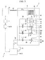
FIG. 3 is a view showing a configuration of a dehumidification apparatus of the compressed air supply apparatus according to the embodiment of the present invention. -
FIG. 4 is a graph showing pressures in the air tanks in the respective cars of the compressed air supply apparatus according to the embodiment of the present invention, showing a difference in pressure gradient according to presence of a relief valve apparatus. -
FIG. 5 is a graph showing a difference in pressure accumulation rate according to presence of the relief valve apparatus of the compressed air supply apparatus according to the embodiment of the present invention. - Hereinafter, a compressed
air supply apparatus 1 according to an embodiment of the present invention will be described. - As shown in
FIG. 1 , the compressedair supply apparatus 1 is installed in railroad vehicles 2 (hereinafter, simply referred to as vehicles 2) connected to each other to generate compressed air A used to manipulate a brake, open and close a door, or the like. - As shown in
FIGS. 1 and2 , the compressedair supply apparatus 1 includes anair compressors 3 installed under a floor of thevehicle 2 and configured to take air thereinto to generate the compressed air A, adehumidification apparatus 4 configured to perform dehumidification of the compressed air A from theair compressor 3, anair tank 5 configured to store the compressed air A passing through thedehumidification apparatus 4, apressure regulator 6 configured to observe a pressure in theair tank 5, and acontrol unit 7 configured to control an operation of theair compressor 3 according to a measurement value of thepressure regulator 6. - Further, the compressed
air supply apparatus 1 includes arelief valve apparatus 80, shown inFIG. 3 , installed in thedehumidification apparatus 4 and configured to release the pressure in theair tank 5 to the atmosphere when the pressure in theair tank 5 is higher than a predetermined value. - Here, the
vehicles 2 of the embodiment, in which 10 cars are connected, constitute one formation, and Table 1 indicates whether or not theair compressor 3, thepressure regulator 6, and theair tank 5 are included in each of the cars, as well as a tank capacity (L) of theair tank 5 of each of the cars. - In addition, the number of cars in the formation of the
vehicles 2, the car number on which each instrument is installed, and a capacity of theair tank 5 indicated in Table 1 are conditions exemplarily described in the embodiment and are not limiting.[Table 1] Car No. 1 2 3 4 5 6 7 8 9 10 Air compressor 3○ ○ ○ Pressure regulator 6,Safety valve 75○ ○ ○ ○ ○ Air tank 5 (Capacity) 400 (L) 520 (L) 520 (L) 400 (L) 400 (L) 400 (L) 300 (L) 520 (L) 300 (L) 700 (L) - As shown in Table 1, the
air compressors 3 are installed in thecars numbers air compressors 3 has a compressormain body 11 configured to compress air introduced from the outside, and anoil separator 21 configured to separate an oil from the compressed air A from the compressormain body 11. - The compressor
main body 11 has amain body case 12, adriving shaft 13 and afixed vortex body 14, which are installed in themain body case 12, a rotatingvortex body 15 attached to thedriving shaft 13 in themain body case 12 and configured to form avortex compression chamber 16 with thefixed vortex body 14, and anelectric motor 17 configured to rotate thedriving shaft 13, which constitute a so-called vortex type air compressor. - The compressor
main body 11 is provided with asuction port 18 in communication with thevortex compression chamber 16 and configured to suction the compressed air A, and anejection port 19 in communication with thevortex compression chamber 16 and configured to eject the compressed air A. - The
oil separator 21 has acyclone section 22 connected to theejection port 19 of the compressormain body 11 and configured to separate a lubricating oil included in the compressed air A introduced from the compressormain body 11, afilter section 23 configured to further separate the lubricating oil after that, and asump section 24 configured to collect the lubricating oil separated by thefilter section 23. - The
sump section 24 is in communication with a bearing section (not shown) in the compressormain body 11. Thesump section 24 conveys a lubricating oil to the bearing section via an oil pre-filter 41, an oil cooler 42 (including a rotary fan 43), and anoil filter 44. - A pressure-limiting
valve 31 configured to secure a pressure of thesump section 24 is installed downstream from theoil separator 21. Thedehumidification apparatus 4 is connected to the pressure-limitingvalve 31. - As shown in
FIG. 3 , thedehumidification apparatus 4 is connected to the pressure-limitingvalve 31 of theair compressor 3 via a first connecting pipe (a connection flow path) 51. - Here, a
flexible pipe 57 such as a hose or the like formed of Teflon (registered trademark) is installed in the first connectingpipe 51 such that vibration from theair compressor 3 is not transmitted to thedehumidification apparatus 4. - The
dehumidification apparatus 4 has anaftercooler 61 configured to cool the compressed air A from theair compressor 3, and anadsorption apparatus 63 and an unloadingvalve 65 installed between theaftercooler 61 and theair tank 5. - A
drain valve 62 is installed in theaftercooler 61, and moisture contained in the compressed air A generated by cooling the compressed air A is discharged from thedrain valve 62. Here, humidity in the compressed air A becomes substantially 100% and the compressed air A is conveyed downward. - The
adsorption apparatus 63 is connected to theaftercooler 61 via a second connecting pipe (a connection flow path) 52, and a third connecting pipe (a connection flow path) 53 connected to oneend 52a of the second connectingpipe 52. Then, starting from an upstream end, theadsorption apparatus 63 includes a switchingvalve 72, twoadsorption sections 71 connected in parallel to the switchingvalve 72,check valves 73 connected to theadsorption sections 71, respectively, and aregeneration throttling section 74 installed between theadsorption sections 71 and thecheck valves 73 to bring the twoadsorption sections 71 in communication with each other. - In the
adsorption apparatus 63, while dehumidification of the compressed air A is performed by absorbing the moisture contained in the compressed air A in one of theadsorption sections 71, some of the compressed air A passes through theregeneration throttling section 74 to enter the other of theadsorption sections 71 after passing through the one of theadsorption sections 71, and dries the other of theadsorption sections 71. Accordingly, dehumidification of the compressed air A can be continuously performed. - A fourth connecting pipe (a connection flow path) 54 is connected to the two
check valves 73 of theadsorption apparatus 63, and theair tank 5 and thedehumidification apparatus 4 are connected via the fourth connectingpipe 54. - The unloading
valve 65 is a valve apparatus installed in parallel at theadsorption apparatus 63 to be branched off from the third connectingpipe 53 and configured to open the third connectingpipe 53 to the atmosphere to eject the compressed air A to the outside. That is, as the third connectingpipe 53 is opened to the atmosphere, the unloadingvalve 65 is used to reduce a load of an electric motor the next time it is started by bringing the entire inside of the compressedair supply apparatus 1 in communication with the atmosphere. - In the
dehumidification apparatus 4, the switchingvalve 72 is in communication with the fourth connectingpipe 54 via anelectromagnetic valves 67, and the unloadingvalve 65 is in communication with the fourth connectingpipe 54 via anelectromagnetic valves 67. - The
air tank 5 stores the compressed air A via thedehumidification apparatus 4 from theair compressor 3 to perform the pressure accumulation. In addition, in the embodiment, as represented in Table 1, theair tanks 5 are installed in the respective cars, and have different capacities at the respective cars. - Here, in the embodiment, the
air tank 5a installed in the 10th car is connected to theair compressor 3 via the shortest first connectingpipe 51, and response of the pressure accumulation in theair tank 5a of the 10th car is fastest. - Here, as represented in Table 1, in the 1st, 4th, 5th, 9th and 10th cars, the
safety valves 75 and thepressure regulators 6 are installed. - The
pressure regulator 6 measures and observes the pressure in theair tank 5. Here, thepressure regulator 6 configured to observe the pressure of theair tank 5 of the 10th car is referred to as a pressure measurement apparatus (a pressure measurement unit) 6a. - The
safety valve 75 is installed in each of thepressure regulators 6 to release the compressed air when the pressure approaches an adjustment pressure to protect the connected instruments, in the case in which the air system malfunctions and the pressure increases. - Specifically, in the embodiment, it is determined as a malfunction when the pressure in the
air tank 5 is 950 kPa, and thesafety valve 75 releases the compressed air into the atmosphere. - The
control unit 7 operates theair compressor 3 when the pressure in theair tank 5a measured by thepressure measurement apparatus 6a is 800 kPa (a first pressure) or less, and stops theair compressor 3 when the pressure exceeds 900 kPa (a second pressure). - Next, the
relief valve apparatus 80 will be described. - The
relief valve apparatus 80 is connected to the oneend 52a of the second connectingpipe 52 via a fifth connecting pipe (a connection flow path) 55 to be bifurcated at the third connectingpipe 53. Therelief valve apparatus 80 and the fourth connectingpipe 54 are connected by a sixth connecting pipe (a connection flow path) 56 having anelectromagnetic valve 67 and come in communication with theair tank 5. - The
relief valve apparatus 80 has a fixed throttling section (a flow-restricting unit, a throttling flow path) 81 installed at a halfway position of the fifth connectingpipe 55, and the valvemain body 82 installed at a downstream side from the fixedthrottling section 81 nearer to theair tank 5. - The fixed
throttling section 81 is a throttling flow path having a smaller diameter than a pipe diameter of the fifth connectingpipe 55, and restricts a flow of the compressed air A. - The fixed
throttling section 81 may not be the throttling flow path, but, for example, may be a throttling valve or the like, or may be integrally formed with the valvemain body 82. That is, any throttling section may be used as long as the flow of the compressed air A at the fifth connectingpipe 55 can be restricted. - The valve
main body 82 opens the sixth connectingpipe 56 to the atmosphere and ejects the compressed air A to the outside when the pressure in theair tank 5a of the 10th car measured by thepressure measurement apparatus 6a reaches 930 kPa (a third pressure), which is higher than 900 kPa, which is the pressure at which theair compressor 3 is stopped. In addition, when the pressure in theair tank 5a is stable and measured by thepressure measurement apparatus 6a as 920 kPa (a fourth pressure), which is lower than 930 kPa and higher than 900 kPa, the valvemain body 82 is rapidly closed. - Here, in the embodiment, the valve
main body 82 has the same configuration as the above-mentionedunloading valve 65 of thedehumidification apparatus 4. - In the above-mentioned compressed
air supply apparatus 1, first, theair compressor 3 is operated, and the pressure accumulation is performed such that the pressure in theair tank 5a is higher than 800 kPa. After that, the operation of theair compressor 3 is stopped by thecontrol unit 7 when the pressure in theair tank 5a measured by thepressure measurement apparatus 6a reaches 900 kPa. - Here, even when the pressure in the
air tank 5a of the 10th car reaches 900 kPa and theair compressor 3 is stopped, as shown inFIG. 4 , a pressure gradient may occur between theair tanks 5 by an imbalance in installation of theair compressors 3 and theair tanks 5 in the formation. - Then, when the pressure gradient is increased and the pressure in some of the
air tanks 5 exceeds 950 kPa (see broken lines ofFIG. 4 ), thesafety valve 75 may release the compressed air and it is determined as an abnormal state. - In this point, in the embodiment, when the pressure in the
air tank 5 reaches 930 kPa, as release into the atmosphere is performed by therelief valve apparatus 80, the pressure in theair tank 5 is relieved. Accordingly, the pressure does not exceed 930 kPa in any of theair tanks 5, and thesafety valve 75 is not operated during the conventional operation (see solid lines ofFIG. 4 ). - Further, in the
relief valve apparatus 80, a flow of the compressed air A between theair compressor 3 and theair tank 5 is restricted by the fixedthrottling section 81. For this reason, even when the valvemain body 82 of therelief valve apparatus 80 opens the sixth connectingpipe 56 to the atmosphere, the pressure is decreased only between theair tank 5 and the fixedthrottling section 81. Meanwhile, the pressure does not abruptly decrease between thefixed throttling section 81 and theair compressor 3. - Accordingly, a high-pressure state needed for the pressure accumulation can be maintained between the
fixed throttling section 81 and theair compressor 3, and when the pressure in theair tank 5 is decreased to 920 kPa (a fourth pressure) after the sixth connectingpipe 56 is opened to the atmosphere by the valvemain body 82, the pressure accumulation inside theair tank 5 can be rapidly performed by closing the sixth connectingpipe 56 by the valvemain body 82 again. - Specifically, as shown in broken lines of
FIG. 5 , if the fixedthrottling section 81 is not formed, when the sixth connectingpipe 56 is opened to the atmosphere by the valvemain body 82 of therelief valve apparatus 80, since the pressure in theair tank 5 is abruptly decreased, time is needed before the pressure accumulation is performed again. Meanwhile, as shown in solid lines ofFIG. 5 , the time before the pressure accumulation is performed again can be reduced by forming the fixedthrottling section 81. - Further, since the
relief valve apparatus 80 is installed in thedehumidification apparatus 4, the apparatus is installed downstream from theflexible pipe 57. For this reason, an influence of the vibration of theair compressor 3 can be reduced, and durability of therelief valve apparatus 80 is improved. - In addition, the
relief valve apparatus 80 is installed in thedehumidification apparatus 4 downstream from theaftercooler 61. For this reason, an influence of heat of the compressed air A at a high temperature and a high pressure by theair compressor 3 can be reduced, and durability of therelief valve apparatus 80 is improved. - Further, since the valve
main body 82 in therelief valve apparatus 80 can be used like the unloadingvalve 65, reduction of a cost due to communization of parts is possible. - According to the compressed
air supply apparatus 1 of the embodiment, as therelief valve apparatus 80 is installed between theair compressor 3 and theair tank 5, thesafety valve 75 does not release the compressed air during a normal operation, and the operation can be performed in a state in which the pressure gradient between theair tanks 5 is reduced, regardless of an installing balance of theair compressors 3 and theair tanks 5 in the formation. - While the exemplary embodiment of the present invention has been described, the present invention is not limited to the above-mentioned embodiment. Addition, omission, substitution and other modifications of components may be made without departing from the spirit of the present invention. The present invention is not limited by the above-mentioned description but limited only by the scope of the accompanying claims.
- For example, when a throttling valve configured to adjust an aperture is used instead of the fixed
throttling section 81 of therelief valve apparatus 80, a degree of throttling can be adjusted. For this reason, according to the above-mentioned adjustment, since a response speed can be appropriately adjusted when the pressure accumulation is performed again after the valvemain body 82 is opened, convenience can be improved. - In addition, as shown in
FIG. 3 , the fixedthrottling section 81 need not to be necessarily installed near the valvemain body 82, and may be installed at least at an upstream side from the valvemain body 82 nearer to theair compressor 3 and downstream from the oneend 52a of the second connectingpipe 52. - Further, when the unloading
valve 65 is not installed in thedehumidification apparatus 4, therelief valve apparatus 80 may be installed upstream from theflexible pipe 57 or theaftercooler 61, but therelief valve apparatus 80 is preferably installed downstream from theflexible pipe 57 and theaftercooler 61. - Furthermore, in the embodiment, the case in which the compressed
air supply apparatus 1 is installed in therailroad vehicle 2 has been described. However, the compressedair supply apparatus 1 is not limited to be installed in therailroad vehicle 2, for example, may be installed in a vehicle of a track-based transportation system using a plurality of cars being connected. - In addition, numerical values of the pressure referred to as 800 kPa, 900 kPa, 920 kPa, 930 kPa and 950 kPa are exemplary values and are not limited thereto.
- The present invention relates to the compressed air supply apparatus installed in the vehicle in which the plurality of, for example, railroad vehicles are connected. According to the compressed air supply apparatus of the embodiment of the present invention, as the relief valve apparatus is installed between the air compressor and the air tank, the operation can be performed in a state in which the pressure gradient between the air tanks is reduced, regardless of an installing balance of the air compressors and the air tanks in the formation.
-
- 1
- compressed air supply apparatus
- 2
- (railroad) vehicle
- 3
- air compressor
- 4
- dehumidification apparatus
- 5
- air tank
- 6
- pressure regulator
- 6a
- pressure measurement apparatus (pressure measurement unit)
- 7
- control unit
- 11
- compressor main body
- 12
- main body case
- 13
- driving shaft
- 14
- fixed vortex body
- 15
- rotating vortex body
- 16
- vortex compression chamber
- 17
- electric motor
- 18
- suction port
- 19
- ejection port
- 21
- oil separator
- 22
- cyclone section
- 23
- filter section
- 24
- sump section
- 31
- pressure-limiting valve
- 41
- oil pre-filter
- 42
- oil cooler
- 43
- rotary fan
- 44
- oil filter
- 51
- first connecting pipe (connection flow path)
- 52
- second connecting pipe (connection flow path)
- 52a
- one end
- 53
- third connecting pipe (connection flow path)
- 54
- fourth connecting pipe (connection flow path)
- 55
- fifth connecting pipe (connection flow path)
- 56
- sixth connecting pipe (connection flow path)
- 57
- flexible pipe
- 61
- aftercooler
- 62
- drain valve
- 63
- adsorption apparatus
- 65
- unloading valve
- 67
- electromagnetic valve
- 71
- adsorption section
- 72
- switching valve
- 73
- check valve
- 74
- regeneration throttling section
- 75
- safety valve
- 80
- relief valve apparatus
- 81
- fixed throttling section (flow-restricting unit)
- 82
- valve main body
- A
- compressed air
Claims (4)
- A compressed air supply apparatus comprising:an air compressor installed in at least one of a plurality of vehicles connected to each other;a plurality of air tanks connected to the air compressor via a connection flow path and installed in each of the plurality of vehicles in communication with each other;a pressure measurement unit configured to measure an air pressure in one air tank connected to the air compressor via a shortest flow path, among the plurality of air tanks;a control unit configured to operate the air compressor when a measurement value of the pressure measurement unit reaches a first pressure or less, and configured to stop the air compressor when the measurement value reaches a second pressure higher than the first pressure; anda plurality of relief valve apparatuses installed in each of the connection flow path between the air compressor and each of the plurality of air tanks, whereinthe relief valve apparatus comprises:a flow-restricting unit configured to restrict an air flow, anda valve main body installed nearer to the air tank than the flow-restricting unit, and configured to open the connection flow path to the atmosphere when the measurement value reaches a third pressure higher than the second pressure and close the connection flow path when the measurement value reaches a fourth pressure higher than the second pressure and lower than the third pressure after the opening.
- The compressed air supply apparatus according to Claim 1, wherein the flow-restricting unit is a throttling flow path having a smaller flow path area than the connection flow path.
- The compressed air supply apparatus according to Claim 1 or 2, wherein the relief valve apparatus is installed downstream from a flexible pipe installed in the connection flow path.
- The compressed air supply apparatus according to any one of Claims 1 to 3, wherein the relief valve apparatus is installed downstream from an aftercooler installed in the connection flow path and configured to dehumidify the compressed air.
Applications Claiming Priority (1)
| Application Number | Priority Date | Filing Date | Title |
|---|---|---|---|
| JP2013021803A JP6004961B2 (en) | 2013-02-06 | 2013-02-06 | Compressed air supply device |
Publications (3)
| Publication Number | Publication Date |
|---|---|
| EP2765042A2 true EP2765042A2 (en) | 2014-08-13 |
| EP2765042A3 EP2765042A3 (en) | 2014-12-24 |
| EP2765042B1 EP2765042B1 (en) | 2016-04-06 |
Family
ID=49752944
Family Applications (1)
| Application Number | Title | Priority Date | Filing Date |
|---|---|---|---|
| EP13194169.2A Not-in-force EP2765042B1 (en) | 2013-02-06 | 2013-11-22 | Compressed air supply apparatus |
Country Status (7)
| Country | Link |
|---|---|
| US (1) | US9500192B2 (en) |
| EP (1) | EP2765042B1 (en) |
| JP (1) | JP6004961B2 (en) |
| KR (1) | KR101475161B1 (en) |
| CN (1) | CN103967747B (en) |
| CA (1) | CA2834016C (en) |
| ES (1) | ES2573653T3 (en) |
Cited By (1)
| Publication number | Priority date | Publication date | Assignee | Title |
|---|---|---|---|---|
| WO2016071130A1 (en) * | 2014-11-03 | 2016-05-12 | Knorr-Bremse Systeme für Schienenfahrzeuge GmbH | Self-regulating network for optimized air supply to rail vehicles |
Families Citing this family (6)
| Publication number | Priority date | Publication date | Assignee | Title |
|---|---|---|---|---|
| US9283944B2 (en) * | 2014-06-17 | 2016-03-15 | New York Air Brake, LLC | Compressor aftercooler bypass with integral water separator |
| AU2014203400A1 (en) * | 2014-06-23 | 2016-01-21 | SMC Pneumatics (Australia) Pty Ltd | Factory compressed air supplies |
| JP2016014381A (en) * | 2014-07-03 | 2016-01-28 | ナブテスコ株式会社 | Air compressor for vehicle |
| TWI621775B (en) * | 2015-05-29 | 2018-04-21 | Nabtesco Corp | Air compression device |
| CN105172774B (en) * | 2015-07-29 | 2017-10-17 | 陈建平 | A kind of automobile air compressor plant |
| EP4674711A1 (en) * | 2024-07-05 | 2026-01-07 | Faiveley Transport Italia S.p.A. | Compressed air distribution systems, vehicles and group of vehicles |
Citations (1)
| Publication number | Priority date | Publication date | Assignee | Title |
|---|---|---|---|---|
| JP3150077U (en) | 2009-01-29 | 2009-04-30 | 三菱重工業株式会社 | Air compressor for railway vehicles |
Family Cites Families (25)
| Publication number | Priority date | Publication date | Assignee | Title |
|---|---|---|---|---|
| US1936827A (en) * | 1929-11-07 | 1933-11-28 | New York Air Brake Co | Air brake |
| US1923141A (en) * | 1930-12-10 | 1933-08-22 | Westinghouse Air Brake Co | Fluid pressure brake |
| US2366044A (en) * | 1943-04-30 | 1944-12-26 | Westinghouse Air Brake Co | Valve device |
| US2515946A (en) * | 1946-06-05 | 1950-07-18 | Westinghouse Air Brake Co | Fluid pressure brake apparatus |
| GB831282A (en) * | 1956-06-28 | 1960-03-30 | Magneti Marelli Spa | Automatic control system for the relief valve for the compressor in a compressed fluid equipment having a plurality of reservoirs |
| JPS5438269B2 (en) * | 1971-12-04 | 1979-11-20 | ||
| US4219312A (en) * | 1978-10-20 | 1980-08-26 | Hitachi, Ltd. | Volume control system for compressor unit |
| JPS61134585A (en) | 1984-12-06 | 1986-06-21 | 東芝セラミックス株式会社 | Thin alumina box pot |
| JPH0110454Y2 (en) | 1985-02-08 | 1989-03-24 | ||
| JP2719416B2 (en) | 1989-08-31 | 1998-02-25 | キヤノン株式会社 | IC card |
| JP2517446Y2 (en) * | 1989-12-27 | 1996-11-20 | 株式会社ナブコ | Air source device protection circuit |
| JP2885903B2 (en) * | 1990-08-03 | 1999-04-26 | 本田技研工業株式会社 | Fluid pressure supply device for vehicles |
| JP2891024B2 (en) | 1992-06-05 | 1999-05-17 | 日立工機株式会社 | Air compression device |
| JPH0624325A (en) * | 1992-07-03 | 1994-02-01 | Central Japan Railway Co | Compressed air supply method for railway vehicles |
| JPH0650264U (en) * | 1992-12-02 | 1994-07-08 | 建通精密工業股▲ひん▼有限公司 | Three-pronged plug |
| US5538331A (en) * | 1995-01-30 | 1996-07-23 | Westinghouse Air Brake Company | Applications of EPIC® 3102 brake equipment to electro-pneumatic systems |
| JP3150077B2 (en) | 1997-02-27 | 2001-03-26 | 九州日本電気株式会社 | Bonding apparatus for resin-coated wire and bonding method using the same |
| JPH11201039A (en) | 1998-01-20 | 1999-07-27 | Mitsubishi Heavy Ind Ltd | Operating method of air compressor |
| KR100290125B1 (en) | 1999-03-18 | 2001-05-15 | 김정자 | A control apparatus of screw comprssor for an railcar |
| CN2451436Y (en) * | 2000-08-12 | 2001-10-03 | 株洲时代电子技术有限公司 | Train air conditioner controller |
| US7055546B2 (en) * | 2003-09-24 | 2006-06-06 | Mclaughlin John E | Fluid intake pressure regulating system |
| US7350878B2 (en) * | 2004-12-27 | 2008-04-01 | New York Air Brake Corporation | Relay configuration for an electro-pneumatic train |
| US7976285B2 (en) * | 2006-06-05 | 2011-07-12 | Paccar Inc | Electronic control for heavy duty truck compressed air charging system |
| CN200965631Y (en) * | 2006-09-07 | 2007-10-24 | 四川长虹电器股份有限公司 | Locomotive air conditioning controller |
| DE102010005091B4 (en) * | 2010-01-18 | 2013-08-08 | Siemens Aktiengesellschaft | Brake arrangement of a rail vehicle |
-
2013
- 2013-02-06 JP JP2013021803A patent/JP6004961B2/en active Active
- 2013-11-13 KR KR1020130137686A patent/KR101475161B1/en not_active Expired - Fee Related
- 2013-11-22 EP EP13194169.2A patent/EP2765042B1/en not_active Not-in-force
- 2013-11-22 CA CA2834016A patent/CA2834016C/en not_active Expired - Fee Related
- 2013-11-22 ES ES13194169.2T patent/ES2573653T3/en active Active
- 2013-11-25 US US14/089,210 patent/US9500192B2/en not_active Expired - Fee Related
- 2013-12-18 CN CN201310698942.7A patent/CN103967747B/en not_active Expired - Fee Related
Patent Citations (1)
| Publication number | Priority date | Publication date | Assignee | Title |
|---|---|---|---|---|
| JP3150077U (en) | 2009-01-29 | 2009-04-30 | 三菱重工業株式会社 | Air compressor for railway vehicles |
Cited By (1)
| Publication number | Priority date | Publication date | Assignee | Title |
|---|---|---|---|---|
| WO2016071130A1 (en) * | 2014-11-03 | 2016-05-12 | Knorr-Bremse Systeme für Schienenfahrzeuge GmbH | Self-regulating network for optimized air supply to rail vehicles |
Also Published As
| Publication number | Publication date |
|---|---|
| US9500192B2 (en) | 2016-11-22 |
| US20140216578A1 (en) | 2014-08-07 |
| CA2834016C (en) | 2015-11-03 |
| CN103967747B (en) | 2016-09-07 |
| CA2834016A1 (en) | 2014-08-06 |
| KR101475161B1 (en) | 2014-12-19 |
| JP2014152666A (en) | 2014-08-25 |
| EP2765042B1 (en) | 2016-04-06 |
| JP6004961B2 (en) | 2016-10-12 |
| KR20140100400A (en) | 2014-08-14 |
| EP2765042A3 (en) | 2014-12-24 |
| CN103967747A (en) | 2014-08-06 |
| ES2573653T3 (en) | 2016-06-09 |
Similar Documents
| Publication | Publication Date | Title |
|---|---|---|
| EP2765042B1 (en) | Compressed air supply apparatus | |
| US20190100070A1 (en) | Air suspension apparatus | |
| JP2009517611A (en) | Operation method of compressed air treatment equipment and compressed air treatment equipment | |
| US20100072837A1 (en) | Motor cooling system | |
| WO2012017939A1 (en) | Air compression device for railway vehicle | |
| CN101163887A (en) | System and method for controlling variable speed compressor during shutdown | |
| JP6876433B2 (en) | How to regenerate a compressed air drying system and a compressed air drying system | |
| CN103671039B (en) | Air compression plant | |
| CN103270302B (en) | Valve arrangement for controlling air delivery to a compressor of a vehicle and compressor system and method for controlling the compressor system | |
| KR101704227B1 (en) | Air compressing apparatus | |
| US10378536B2 (en) | Air compressor discharge system | |
| JP5503326B2 (en) | Air compressor for railway vehicles | |
| US11879463B2 (en) | Refueling screw compressor | |
| JP6000108B2 (en) | Oil return circuit and air compression apparatus provided with the same | |
| US9651040B2 (en) | Unloader valve apparatus for an air compressor | |
| KR20130048073A (en) | Pneumatic control system of air spring for vehicle | |
| EP2878785A1 (en) | System for pressurizing a cooling circuit of an internal combustion engine for industrial vehicles equipped with a compressed air tank | |
| US9835147B2 (en) | Dual control valve for reciprocating compressor unloader system | |
| WO2012053438A1 (en) | Air compressing device for railway vehicle | |
| KR20120088626A (en) | Safety type air suspension apparatus | |
| JP2007231740A (en) | Method and apparatus for determining strainer clogging | |
| HK1183334B (en) | Air compression device for railway vehicle | |
| KR20090093359A (en) | Safety type air suspension apparatus |
Legal Events
| Date | Code | Title | Description |
|---|---|---|---|
| PUAI | Public reference made under article 153(3) epc to a published international application that has entered the european phase |
Free format text: ORIGINAL CODE: 0009012 |
|
| 17P | Request for examination filed |
Effective date: 20131122 |
|
| AK | Designated contracting states |
Kind code of ref document: A2 Designated state(s): AL AT BE BG CH CY CZ DE DK EE ES FI FR GB GR HR HU IE IS IT LI LT LU LV MC MK MT NL NO PL PT RO RS SE SI SK SM TR |
|
| AX | Request for extension of the european patent |
Extension state: BA ME |
|
| PUAL | Search report despatched |
Free format text: ORIGINAL CODE: 0009013 |
|
| RIN1 | Information on inventor provided before grant (corrected) |
Inventor name: KOBAYASHI, GAKUJI Inventor name: TANIYAMA, NORIYUKI Inventor name: TAKAHISA, INUI Inventor name: TANAKA, SHINICHIRO Inventor name: WATANABE, TOMOKI |
|
| AK | Designated contracting states |
Kind code of ref document: A3 Designated state(s): AL AT BE BG CH CY CZ DE DK EE ES FI FR GB GR HR HU IE IS IT LI LT LU LV MC MK MT NL NO PL PT RO RS SE SI SK SM TR |
|
| AX | Request for extension of the european patent |
Extension state: BA ME |
|
| RIC1 | Information provided on ipc code assigned before grant |
Ipc: B60T 15/02 20060101AFI20141119BHEP Ipc: F04B 49/03 20060101ALI20141119BHEP Ipc: F04B 41/02 20060101ALI20141119BHEP Ipc: B60T 17/02 20060101ALI20141119BHEP Ipc: B60T 15/04 20060101ALI20141119BHEP |
|
| GRAP | Despatch of communication of intention to grant a patent |
Free format text: ORIGINAL CODE: EPIDOSNIGR1 |
|
| RIC1 | Information provided on ipc code assigned before grant |
Ipc: F04B 41/02 20060101ALI20150721BHEP Ipc: F04B 49/03 20060101ALI20150721BHEP Ipc: B60T 15/02 20060101AFI20150721BHEP Ipc: B60T 17/02 20060101ALI20150721BHEP Ipc: B60T 15/04 20060101ALI20150721BHEP |
|
| INTG | Intention to grant announced |
Effective date: 20150818 |
|
| GRAS | Grant fee paid |
Free format text: ORIGINAL CODE: EPIDOSNIGR3 |
|
| RAP1 | Party data changed (applicant data changed or rights of an application transferred) |
Owner name: CENTRAL JAPAN RAILWAY COMPANY |
|
| GRAA | (expected) grant |
Free format text: ORIGINAL CODE: 0009210 |
|
| AK | Designated contracting states |
Kind code of ref document: B1 Designated state(s): AL AT BE BG CH CY CZ DE DK EE ES FI FR GB GR HR HU IE IS IT LI LT LU LV MC MK MT NL NO PL PT RO RS SE SI SK SM TR |
|
| REG | Reference to a national code |
Ref country code: GB Ref legal event code: FG4D |
|
| REG | Reference to a national code |
Ref country code: AT Ref legal event code: REF Ref document number: 787421 Country of ref document: AT Kind code of ref document: T Effective date: 20160415 Ref country code: CH Ref legal event code: EP |
|
| REG | Reference to a national code |
Ref country code: IE Ref legal event code: FG4D |
|
| REG | Reference to a national code |
Ref country code: DE Ref legal event code: R096 Ref document number: 602013006161 Country of ref document: DE |
|
| REG | Reference to a national code |
Ref country code: ES Ref legal event code: FG2A Ref document number: 2573653 Country of ref document: ES Kind code of ref document: T3 Effective date: 20160609 |
|
| REG | Reference to a national code |
Ref country code: LT Ref legal event code: MG4D Ref country code: NL Ref legal event code: MP Effective date: 20160406 |
|
| REG | Reference to a national code |
Ref country code: AT Ref legal event code: MK05 Ref document number: 787421 Country of ref document: AT Kind code of ref document: T Effective date: 20160406 |
|
| PG25 | Lapsed in a contracting state [announced via postgrant information from national office to epo] |
Ref country code: NL Free format text: LAPSE BECAUSE OF FAILURE TO SUBMIT A TRANSLATION OF THE DESCRIPTION OR TO PAY THE FEE WITHIN THE PRESCRIBED TIME-LIMIT Effective date: 20160406 |
|
| PG25 | Lapsed in a contracting state [announced via postgrant information from national office to epo] |
Ref country code: NO Free format text: LAPSE BECAUSE OF FAILURE TO SUBMIT A TRANSLATION OF THE DESCRIPTION OR TO PAY THE FEE WITHIN THE PRESCRIBED TIME-LIMIT Effective date: 20160706 Ref country code: LT Free format text: LAPSE BECAUSE OF FAILURE TO SUBMIT A TRANSLATION OF THE DESCRIPTION OR TO PAY THE FEE WITHIN THE PRESCRIBED TIME-LIMIT Effective date: 20160406 Ref country code: FI Free format text: LAPSE BECAUSE OF FAILURE TO SUBMIT A TRANSLATION OF THE DESCRIPTION OR TO PAY THE FEE WITHIN THE PRESCRIBED TIME-LIMIT Effective date: 20160406 Ref country code: PL Free format text: LAPSE BECAUSE OF FAILURE TO SUBMIT A TRANSLATION OF THE DESCRIPTION OR TO PAY THE FEE WITHIN THE PRESCRIBED TIME-LIMIT Effective date: 20160406 Ref country code: IS Free format text: LAPSE BECAUSE OF FAILURE TO SUBMIT A TRANSLATION OF THE DESCRIPTION OR TO PAY THE FEE WITHIN THE PRESCRIBED TIME-LIMIT Effective date: 20160806 |
|
| REG | Reference to a national code |
Ref country code: FR Ref legal event code: PLFP Year of fee payment: 4 |
|
| PG25 | Lapsed in a contracting state [announced via postgrant information from national office to epo] |
Ref country code: HR Free format text: LAPSE BECAUSE OF FAILURE TO SUBMIT A TRANSLATION OF THE DESCRIPTION OR TO PAY THE FEE WITHIN THE PRESCRIBED TIME-LIMIT Effective date: 20160406 Ref country code: PT Free format text: LAPSE BECAUSE OF FAILURE TO SUBMIT A TRANSLATION OF THE DESCRIPTION OR TO PAY THE FEE WITHIN THE PRESCRIBED TIME-LIMIT Effective date: 20160808 Ref country code: RS Free format text: LAPSE BECAUSE OF FAILURE TO SUBMIT A TRANSLATION OF THE DESCRIPTION OR TO PAY THE FEE WITHIN THE PRESCRIBED TIME-LIMIT Effective date: 20160406 Ref country code: GR Free format text: LAPSE BECAUSE OF FAILURE TO SUBMIT A TRANSLATION OF THE DESCRIPTION OR TO PAY THE FEE WITHIN THE PRESCRIBED TIME-LIMIT Effective date: 20160707 Ref country code: LV Free format text: LAPSE BECAUSE OF FAILURE TO SUBMIT A TRANSLATION OF THE DESCRIPTION OR TO PAY THE FEE WITHIN THE PRESCRIBED TIME-LIMIT Effective date: 20160406 Ref country code: SE Free format text: LAPSE BECAUSE OF FAILURE TO SUBMIT A TRANSLATION OF THE DESCRIPTION OR TO PAY THE FEE WITHIN THE PRESCRIBED TIME-LIMIT Effective date: 20160406 Ref country code: AT Free format text: LAPSE BECAUSE OF FAILURE TO SUBMIT A TRANSLATION OF THE DESCRIPTION OR TO PAY THE FEE WITHIN THE PRESCRIBED TIME-LIMIT Effective date: 20160406 |
|
| PG25 | Lapsed in a contracting state [announced via postgrant information from national office to epo] |
Ref country code: BE Free format text: LAPSE BECAUSE OF FAILURE TO SUBMIT A TRANSLATION OF THE DESCRIPTION OR TO PAY THE FEE WITHIN THE PRESCRIBED TIME-LIMIT Effective date: 20160406 |
|
| REG | Reference to a national code |
Ref country code: DE Ref legal event code: R097 Ref document number: 602013006161 Country of ref document: DE |
|
| PG25 | Lapsed in a contracting state [announced via postgrant information from national office to epo] |
Ref country code: DK Free format text: LAPSE BECAUSE OF FAILURE TO SUBMIT A TRANSLATION OF THE DESCRIPTION OR TO PAY THE FEE WITHIN THE PRESCRIBED TIME-LIMIT Effective date: 20160406 Ref country code: RO Free format text: LAPSE BECAUSE OF FAILURE TO SUBMIT A TRANSLATION OF THE DESCRIPTION OR TO PAY THE FEE WITHIN THE PRESCRIBED TIME-LIMIT Effective date: 20160406 Ref country code: EE Free format text: LAPSE BECAUSE OF FAILURE TO SUBMIT A TRANSLATION OF THE DESCRIPTION OR TO PAY THE FEE WITHIN THE PRESCRIBED TIME-LIMIT Effective date: 20160406 Ref country code: CZ Free format text: LAPSE BECAUSE OF FAILURE TO SUBMIT A TRANSLATION OF THE DESCRIPTION OR TO PAY THE FEE WITHIN THE PRESCRIBED TIME-LIMIT Effective date: 20160406 Ref country code: SK Free format text: LAPSE BECAUSE OF FAILURE TO SUBMIT A TRANSLATION OF THE DESCRIPTION OR TO PAY THE FEE WITHIN THE PRESCRIBED TIME-LIMIT Effective date: 20160406 |
|
| PGFP | Annual fee paid to national office [announced via postgrant information from national office to epo] |
Ref country code: FR Payment date: 20161124 Year of fee payment: 4 Ref country code: DE Payment date: 20161130 Year of fee payment: 4 |
|
| PLBE | No opposition filed within time limit |
Free format text: ORIGINAL CODE: 0009261 |
|
| STAA | Information on the status of an ep patent application or granted ep patent |
Free format text: STATUS: NO OPPOSITION FILED WITHIN TIME LIMIT |
|
| PG25 | Lapsed in a contracting state [announced via postgrant information from national office to epo] |
Ref country code: SM Free format text: LAPSE BECAUSE OF FAILURE TO SUBMIT A TRANSLATION OF THE DESCRIPTION OR TO PAY THE FEE WITHIN THE PRESCRIBED TIME-LIMIT Effective date: 20160406 |
|
| PGFP | Annual fee paid to national office [announced via postgrant information from national office to epo] |
Ref country code: ES Payment date: 20161124 Year of fee payment: 4 Ref country code: IT Payment date: 20161130 Year of fee payment: 4 |
|
| 26N | No opposition filed |
Effective date: 20170110 |
|
| PG25 | Lapsed in a contracting state [announced via postgrant information from national office to epo] |
Ref country code: SI Free format text: LAPSE BECAUSE OF FAILURE TO SUBMIT A TRANSLATION OF THE DESCRIPTION OR TO PAY THE FEE WITHIN THE PRESCRIBED TIME-LIMIT Effective date: 20160406 |
|
| REG | Reference to a national code |
Ref country code: CH Ref legal event code: PL |
|
| PG25 | Lapsed in a contracting state [announced via postgrant information from national office to epo] |
Ref country code: LI Free format text: LAPSE BECAUSE OF NON-PAYMENT OF DUE FEES Effective date: 20161130 Ref country code: CH Free format text: LAPSE BECAUSE OF NON-PAYMENT OF DUE FEES Effective date: 20161130 |
|
| REG | Reference to a national code |
Ref country code: IE Ref legal event code: MM4A |
|
| PG25 | Lapsed in a contracting state [announced via postgrant information from national office to epo] |
Ref country code: LU Free format text: LAPSE BECAUSE OF NON-PAYMENT OF DUE FEES Effective date: 20161130 |
|
| PG25 | Lapsed in a contracting state [announced via postgrant information from national office to epo] |
Ref country code: IE Free format text: LAPSE BECAUSE OF NON-PAYMENT OF DUE FEES Effective date: 20161122 |
|
| PG25 | Lapsed in a contracting state [announced via postgrant information from national office to epo] |
Ref country code: HU Free format text: LAPSE BECAUSE OF FAILURE TO SUBMIT A TRANSLATION OF THE DESCRIPTION OR TO PAY THE FEE WITHIN THE PRESCRIBED TIME-LIMIT; INVALID AB INITIO Effective date: 20131122 |
|
| REG | Reference to a national code |
Ref country code: DE Ref legal event code: R119 Ref document number: 602013006161 Country of ref document: DE |
|
| PG25 | Lapsed in a contracting state [announced via postgrant information from national office to epo] |
Ref country code: MK Free format text: LAPSE BECAUSE OF FAILURE TO SUBMIT A TRANSLATION OF THE DESCRIPTION OR TO PAY THE FEE WITHIN THE PRESCRIBED TIME-LIMIT Effective date: 20160406 Ref country code: CY Free format text: LAPSE BECAUSE OF FAILURE TO SUBMIT A TRANSLATION OF THE DESCRIPTION OR TO PAY THE FEE WITHIN THE PRESCRIBED TIME-LIMIT Effective date: 20160406 Ref country code: MC Free format text: LAPSE BECAUSE OF FAILURE TO SUBMIT A TRANSLATION OF THE DESCRIPTION OR TO PAY THE FEE WITHIN THE PRESCRIBED TIME-LIMIT Effective date: 20160406 |
|
| GBPC | Gb: european patent ceased through non-payment of renewal fee |
Effective date: 20171122 |
|
| PG25 | Lapsed in a contracting state [announced via postgrant information from national office to epo] |
Ref country code: BG Free format text: LAPSE BECAUSE OF FAILURE TO SUBMIT A TRANSLATION OF THE DESCRIPTION OR TO PAY THE FEE WITHIN THE PRESCRIBED TIME-LIMIT Effective date: 20160406 |
|
| REG | Reference to a national code |
Ref country code: FR Ref legal event code: ST Effective date: 20180731 |
|
| PG25 | Lapsed in a contracting state [announced via postgrant information from national office to epo] |
Ref country code: MT Free format text: LAPSE BECAUSE OF NON-PAYMENT OF DUE FEES Effective date: 20161122 |
|
| PG25 | Lapsed in a contracting state [announced via postgrant information from national office to epo] |
Ref country code: IT Free format text: LAPSE BECAUSE OF NON-PAYMENT OF DUE FEES Effective date: 20171122 Ref country code: TR Free format text: LAPSE BECAUSE OF FAILURE TO SUBMIT A TRANSLATION OF THE DESCRIPTION OR TO PAY THE FEE WITHIN THE PRESCRIBED TIME-LIMIT Effective date: 20160406 Ref country code: FR Free format text: LAPSE BECAUSE OF NON-PAYMENT OF DUE FEES Effective date: 20171130 Ref country code: AL Free format text: LAPSE BECAUSE OF FAILURE TO SUBMIT A TRANSLATION OF THE DESCRIPTION OR TO PAY THE FEE WITHIN THE PRESCRIBED TIME-LIMIT Effective date: 20160406 Ref country code: DE Free format text: LAPSE BECAUSE OF NON-PAYMENT OF DUE FEES Effective date: 20180602 |
|
| PG25 | Lapsed in a contracting state [announced via postgrant information from national office to epo] |
Ref country code: GB Free format text: LAPSE BECAUSE OF NON-PAYMENT OF DUE FEES Effective date: 20171122 |
|
| REG | Reference to a national code |
Ref country code: ES Ref legal event code: FD2A Effective date: 20181221 |
|
| PG25 | Lapsed in a contracting state [announced via postgrant information from national office to epo] |
Ref country code: ES Free format text: LAPSE BECAUSE OF NON-PAYMENT OF DUE FEES Effective date: 20171123 |