EP2764985A1 - Casting cup assembly for forming an ophthalmic device - Google Patents
Casting cup assembly for forming an ophthalmic device Download PDFInfo
- Publication number
- EP2764985A1 EP2764985A1 EP14154522.8A EP14154522A EP2764985A1 EP 2764985 A1 EP2764985 A1 EP 2764985A1 EP 14154522 A EP14154522 A EP 14154522A EP 2764985 A1 EP2764985 A1 EP 2764985A1
- Authority
- EP
- European Patent Office
- Prior art keywords
- mold
- ring
- frontcurve
- basecurve
- assembly
- Prior art date
- Legal status (The legal status is an assumption and is not a legal conclusion. Google has not performed a legal analysis and makes no representation as to the accuracy of the status listed.)
- Withdrawn
Links
- 238000005266 casting Methods 0.000 title claims abstract description 31
- 238000000034 method Methods 0.000 claims description 10
- 230000007547 defect Effects 0.000 abstract description 24
- 239000011541 reaction mixture Substances 0.000 description 11
- 238000006116 polymerization reaction Methods 0.000 description 6
- 230000003287 optical effect Effects 0.000 description 4
- 239000004593 Epoxy Substances 0.000 description 3
- 230000015572 biosynthetic process Effects 0.000 description 3
- 238000004519 manufacturing process Methods 0.000 description 3
- 239000000178 monomer Substances 0.000 description 3
- 229920000642 polymer Polymers 0.000 description 3
- 239000000463 material Substances 0.000 description 2
- 239000000203 mixture Substances 0.000 description 2
- 238000010420 art technique Methods 0.000 description 1
- 230000004888 barrier function Effects 0.000 description 1
- 230000008901 benefit Effects 0.000 description 1
- 238000002474 experimental method Methods 0.000 description 1
- 239000012530 fluid Substances 0.000 description 1
- 230000036571 hydration Effects 0.000 description 1
- 238000006703 hydration reaction Methods 0.000 description 1
- 238000007689 inspection Methods 0.000 description 1
- 230000013011 mating Effects 0.000 description 1
- 230000007246 mechanism Effects 0.000 description 1
- 230000004048 modification Effects 0.000 description 1
- 238000012986 modification Methods 0.000 description 1
- 230000008569 process Effects 0.000 description 1
- 230000009467 reduction Effects 0.000 description 1
- 238000007788 roughening Methods 0.000 description 1
- 238000007789 sealing Methods 0.000 description 1
- 125000006850 spacer group Chemical group 0.000 description 1
- 239000010409 thin film Substances 0.000 description 1
Images




Classifications
-
- B—PERFORMING OPERATIONS; TRANSPORTING
- B23—MACHINE TOOLS; METAL-WORKING NOT OTHERWISE PROVIDED FOR
- B23B—TURNING; BORING
- B23B1/00—Methods for turning or working essentially requiring the use of turning-machines; Use of auxiliary equipment in connection with such methods
-
- B—PERFORMING OPERATIONS; TRANSPORTING
- B29—WORKING OF PLASTICS; WORKING OF SUBSTANCES IN A PLASTIC STATE IN GENERAL
- B29C—SHAPING OR JOINING OF PLASTICS; SHAPING OF MATERIAL IN A PLASTIC STATE, NOT OTHERWISE PROVIDED FOR; AFTER-TREATMENT OF THE SHAPED PRODUCTS, e.g. REPAIRING
- B29C33/00—Moulds or cores; Details thereof or accessories therefor
- B29C33/10—Moulds or cores; Details thereof or accessories therefor with incorporated venting means
-
- B—PERFORMING OPERATIONS; TRANSPORTING
- B29—WORKING OF PLASTICS; WORKING OF SUBSTANCES IN A PLASTIC STATE IN GENERAL
- B29C—SHAPING OR JOINING OF PLASTICS; SHAPING OF MATERIAL IN A PLASTIC STATE, NOT OTHERWISE PROVIDED FOR; AFTER-TREATMENT OF THE SHAPED PRODUCTS, e.g. REPAIRING
- B29C33/00—Moulds or cores; Details thereof or accessories therefor
- B29C33/30—Mounting, exchanging or centering
- B29C33/303—Mounting, exchanging or centering centering mould parts or halves, e.g. during mounting
-
- B—PERFORMING OPERATIONS; TRANSPORTING
- B29—WORKING OF PLASTICS; WORKING OF SUBSTANCES IN A PLASTIC STATE IN GENERAL
- B29C—SHAPING OR JOINING OF PLASTICS; SHAPING OF MATERIAL IN A PLASTIC STATE, NOT OTHERWISE PROVIDED FOR; AFTER-TREATMENT OF THE SHAPED PRODUCTS, e.g. REPAIRING
- B29C33/00—Moulds or cores; Details thereof or accessories therefor
- B29C33/38—Moulds or cores; Details thereof or accessories therefor characterised by the material or the manufacturing process
- B29C33/3842—Manufacturing moulds, e.g. shaping the mould surface by machining
-
- B—PERFORMING OPERATIONS; TRANSPORTING
- B29—WORKING OF PLASTICS; WORKING OF SUBSTANCES IN A PLASTIC STATE IN GENERAL
- B29C—SHAPING OR JOINING OF PLASTICS; SHAPING OF MATERIAL IN A PLASTIC STATE, NOT OTHERWISE PROVIDED FOR; AFTER-TREATMENT OF THE SHAPED PRODUCTS, e.g. REPAIRING
- B29C33/00—Moulds or cores; Details thereof or accessories therefor
- B29C33/42—Moulds or cores; Details thereof or accessories therefor characterised by the shape of the moulding surface, e.g. ribs or grooves
-
- B—PERFORMING OPERATIONS; TRANSPORTING
- B29—WORKING OF PLASTICS; WORKING OF SUBSTANCES IN A PLASTIC STATE IN GENERAL
- B29C—SHAPING OR JOINING OF PLASTICS; SHAPING OF MATERIAL IN A PLASTIC STATE, NOT OTHERWISE PROVIDED FOR; AFTER-TREATMENT OF THE SHAPED PRODUCTS, e.g. REPAIRING
- B29C39/00—Shaping by casting, i.e. introducing the moulding material into a mould or between confining surfaces without significant moulding pressure; Apparatus therefor
- B29C39/22—Component parts, details or accessories; Auxiliary operations
- B29C39/24—Feeding the material into the mould
-
- B—PERFORMING OPERATIONS; TRANSPORTING
- B29—WORKING OF PLASTICS; WORKING OF SUBSTANCES IN A PLASTIC STATE IN GENERAL
- B29C—SHAPING OR JOINING OF PLASTICS; SHAPING OF MATERIAL IN A PLASTIC STATE, NOT OTHERWISE PROVIDED FOR; AFTER-TREATMENT OF THE SHAPED PRODUCTS, e.g. REPAIRING
- B29C41/00—Shaping by coating a mould, core or other substrate, i.e. by depositing material and stripping-off the shaped article; Apparatus therefor
- B29C41/02—Shaping by coating a mould, core or other substrate, i.e. by depositing material and stripping-off the shaped article; Apparatus therefor for making articles of definite length, i.e. discrete articles
- B29C41/20—Shaping by coating a mould, core or other substrate, i.e. by depositing material and stripping-off the shaped article; Apparatus therefor for making articles of definite length, i.e. discrete articles incorporating preformed parts or layers, e.g. moulding inserts or for coating articles
-
- B—PERFORMING OPERATIONS; TRANSPORTING
- B29—WORKING OF PLASTICS; WORKING OF SUBSTANCES IN A PLASTIC STATE IN GENERAL
- B29C—SHAPING OR JOINING OF PLASTICS; SHAPING OF MATERIAL IN A PLASTIC STATE, NOT OTHERWISE PROVIDED FOR; AFTER-TREATMENT OF THE SHAPED PRODUCTS, e.g. REPAIRING
- B29C45/00—Injection moulding, i.e. forcing the required volume of moulding material through a nozzle into a closed mould; Apparatus therefor
- B29C45/17—Component parts, details or accessories; Auxiliary operations
- B29C45/26—Moulds
-
- B—PERFORMING OPERATIONS; TRANSPORTING
- B29—WORKING OF PLASTICS; WORKING OF SUBSTANCES IN A PLASTIC STATE IN GENERAL
- B29D—PRODUCING PARTICULAR ARTICLES FROM PLASTICS OR FROM SUBSTANCES IN A PLASTIC STATE
- B29D11/00—Producing optical elements, e.g. lenses or prisms
- B29D11/00009—Production of simple or compound lenses
- B29D11/00038—Production of contact lenses
-
- B—PERFORMING OPERATIONS; TRANSPORTING
- B29—WORKING OF PLASTICS; WORKING OF SUBSTANCES IN A PLASTIC STATE IN GENERAL
- B29D—PRODUCING PARTICULAR ARTICLES FROM PLASTICS OR FROM SUBSTANCES IN A PLASTIC STATE
- B29D11/00—Producing optical elements, e.g. lenses or prisms
- B29D11/00009—Production of simple or compound lenses
- B29D11/0048—Moulds for lenses
-
- B—PERFORMING OPERATIONS; TRANSPORTING
- B29—WORKING OF PLASTICS; WORKING OF SUBSTANCES IN A PLASTIC STATE IN GENERAL
- B29D—PRODUCING PARTICULAR ARTICLES FROM PLASTICS OR FROM SUBSTANCES IN A PLASTIC STATE
- B29D11/00—Producing optical elements, e.g. lenses or prisms
- B29D11/00009—Production of simple or compound lenses
- B29D11/0048—Moulds for lenses
- B29D11/005—Moulds for lenses having means for aligning the front and back moulds
-
- B—PERFORMING OPERATIONS; TRANSPORTING
- B29—WORKING OF PLASTICS; WORKING OF SUBSTANCES IN A PLASTIC STATE IN GENERAL
- B29D—PRODUCING PARTICULAR ARTICLES FROM PLASTICS OR FROM SUBSTANCES IN A PLASTIC STATE
- B29D11/00—Producing optical elements, e.g. lenses or prisms
- B29D11/02—Artificial eyes from organic plastic material
-
- G—PHYSICS
- G02—OPTICS
- G02C—SPECTACLES; SUNGLASSES OR GOGGLES INSOFAR AS THEY HAVE THE SAME FEATURES AS SPECTACLES; CONTACT LENSES
- G02C7/00—Optical parts
- G02C7/02—Lenses; Lens systems ; Methods of designing lenses
- G02C7/04—Contact lenses for the eyes
-
- B—PERFORMING OPERATIONS; TRANSPORTING
- B29—WORKING OF PLASTICS; WORKING OF SUBSTANCES IN A PLASTIC STATE IN GENERAL
- B29D—PRODUCING PARTICULAR ARTICLES FROM PLASTICS OR FROM SUBSTANCES IN A PLASTIC STATE
- B29D11/00—Producing optical elements, e.g. lenses or prisms
-
- B—PERFORMING OPERATIONS; TRANSPORTING
- B29—WORKING OF PLASTICS; WORKING OF SUBSTANCES IN A PLASTIC STATE IN GENERAL
- B29L—INDEXING SCHEME ASSOCIATED WITH SUBCLASS B29C, RELATING TO PARTICULAR ARTICLES
- B29L2011/00—Optical elements, e.g. lenses, prisms
- B29L2011/0016—Lenses
- B29L2011/0041—Contact lenses
-
- C—CHEMISTRY; METALLURGY
- C08—ORGANIC MACROMOLECULAR COMPOUNDS; THEIR PREPARATION OR CHEMICAL WORKING-UP; COMPOSITIONS BASED THEREON
- C08L—COMPOSITIONS OF MACROMOLECULAR COMPOUNDS
- C08L83/00—Compositions of macromolecular compounds obtained by reactions forming in the main chain of the macromolecule a linkage containing silicon with or without sulfur, nitrogen, oxygen or carbon only; Compositions of derivatives of such polymers
- C08L83/04—Polysiloxanes
-
- Y—GENERAL TAGGING OF NEW TECHNOLOGICAL DEVELOPMENTS; GENERAL TAGGING OF CROSS-SECTIONAL TECHNOLOGIES SPANNING OVER SEVERAL SECTIONS OF THE IPC; TECHNICAL SUBJECTS COVERED BY FORMER USPC CROSS-REFERENCE ART COLLECTIONS [XRACs] AND DIGESTS
- Y10—TECHNICAL SUBJECTS COVERED BY FORMER USPC
- Y10T—TECHNICAL SUBJECTS COVERED BY FORMER US CLASSIFICATION
- Y10T82/00—Turning
- Y10T82/10—Process of turning
Definitions
- This invention relates, in one embodiment, to a casting cup assembly for forming ophthalmic devices such as contact lenses.
- the casting cup assembly includes a basecurve mold, which forms the portion of the device that rests against the eye, and a frontcurve mold, which forms the portion of the device facing away from the eye.
- a reaction mixture which includes one or more polymerizable monomers and other components, is disposed in the frontcurve mold. Thereafter, the basecurve mold is pressed against the frontcurve mold and the reaction mixture is forced to adopt the shape of the volume defined between the two molds. After properly being positioned, the reaction mixture is subjected to polymerization conditions (e.g. photopolymerization or other suitable technique).
- the resulting polymer is removed from the casting cup assembly and subjected to post-polymerization processing (e.g. rinsing, hydration, etc) to provide a finished ophthalmic device.
- post-polymerization processing e.g. rinsing, hydration, etc
- careful inspection of the lenses often reveals a substantial number of the lenses contain defects.
- Defects include a variety of fabrication errors such as holes in the lenses, tears in the edges, the presence rings of excess polymer around the ophthalmic device, and other similar defects. Therefore, an improved method for providing ophthalmic devices is desired that reduces the occurrence of these defects.
- a casting cup assembly comprising precision manufactured frontcurve and basecurve molds which include a ring that circumscribes the respective concave and convex mold surface.
- the rings align with high precision and prevent de-centering and tilting of the concave and convex mold surfaces which, in turn, reduces edge defects.
- An advantage that may be realized in the practice of the disclosedcasting cup assembly is the reduction of edge defects by minimizing the de-centering and tilting of the concave and convex mold surface surfaces of a casting cup assembly.
- a casting cup assembly comprises a frontcurve mold with a concave mold surface circumscribed by a ring.
- the assembly further comprises a basecurve mold with a convex mold surface and a second ring.
- the casting cup assembly may comprise a frontcurve mold with a concave mold surface circumscribed by a ring.
- the assembly may further comprise a basecurve mold with a convex mold surface and a second ring.
- the basecurve may have a textured surface that is continuous with the convex mold surface.
- the textured surface may be between the base of the convex mold surface and the second ring.
- a method of forming a casting cup assembly includes the step of precision lathing a casting cup assembly.
- composition “comprising” encompasses “including” as well as “consisting” and “consisting essentially of” e.g. a composition “comprising” X may consist exclusively of X or may include something additional e.g. X + Y.
- Casting cup assembly 100 includes frontcurve mold 102 andbasecurve mold 104 that mate to define a volume 106. An ophthalmic device is cured within this volume 106. In practice, these mold pieces are often not properly centered and/or become tilted.
- FIG. 2A provides a schematic top-view that depicts de-centering of a convex mold 204 (centered about point 202) disposed within a concave mold 200 (centered about point 206).
- the center points are offset by eccentricity 208, resulting the distance 210 on one side of the mold being less than the distance 212 on the other side of the mold.
- the reaction mixture is cured, the non-hydrated, but fully cured lenses, are immersed in an epoxy mixture and the epoxy cured to lock the lenses in a fixed position.
- the epoxy and locked lenses are subsequently sliced in half, polished, and analyzed under a microscope for defects. In those situations where the two molds were not centered, edge defects (chips, tears, rings, etc) were more common.
- FIG. 1 edge defects
- FIG. 2B provides a cross-sectional view showing mold pieces are not properly centered. Due to the de-centering in FIG. 2B , the volume 106 is not properly sealed. See distance 212. This improper seal translates into edge defects when the resulting lens is de-molded.
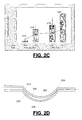
- FIG. 2C graphically depicts the results of certain de-centering experiments.
- the graph in FIG. 2C correlates eccentricity (in microns) to edge defects.
- lenses with high edge defects were measured with respect to the distance between a first side (214) and a second side (216).
- approximately a ten micron gap is present showing the eccentricity.
- lenses with low edge defects were measured in a similar fashion (first side 218, second side 220) and approximately a five micron eccentricity is shown.
- FIG. 2D provides a schematic cross-sectional view that depicts tilting of a convex mold 200 disposed within a concave mold 204.
- Volume 106 is not properly sealed as show by the formation of distance 212. The edge defects associated with such an improper seal are still problematic.
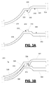
- FIGS. 3A and 3B are profile views of a portion of casting cup assembly 300 shown before ( FIG. 3A ) and after ( FIG. 3B ) basecurve mold 304 is disposed on frontcurve mold 302.
- Frontcurve mold 302 includes a concave mold surface 306 which forms the forward-facing portion of the ophthalmic lens.
- the perimeter 310 of concave mold surface 306 is sized to receive convex mold surface 316 of basecurve mold 304.
- Frontcurve mold 302 further includes a planar top surface 312 that is contiguous with perimeter 310.
- a first ring 314 circumscribes concave mold surface 306 and extends from the top-side of planar top surface 312 and above perimeter 310.
- the ring may be a continuous ring.
- the ring is precision manufactured with respect to the knife edge of the frontcurve mold 302.
- First ring 314 provides the first half of an interlocking feature described in further detail below. This interlocking feature helps minimize de-centering and tilting of concave mold surface 306 and convex mold surface 316.
- Basecurve mold 304 includes convex mold surface 316 which forms the portion of the ophthalmic lens that contacts an eye.
- the perimeter 320 of convex mold surface 316 is sized to be disposed just outside perimeter 310 when assembly 300 is formed with the adjacent planar region 330 contiguous with perimeter 320.
- the curvature of concave mold surface 306 and convex mold surface 316 are different such that, when basecurve mold 304 is disposed on frontcurve mold 302, a stop 326 is created which defines volume 328.
- the shape of volume 328 determines certain physical parameters of the resulting ophthalmic lens.
- Basecurve mold 304 includes a second ring 324 which, may be a continuous ring.
- the second ring is precision manufactured with respect to the axis of the basecurve mold optical surface.
- the second ring 324 circumscribes the convex mold surface 316 and extends from the bottom surface 322 past the perimeter 320. Second ring 324 provides the second half of the interlocking feature.
- FIG. 4A depicts the top of frontcurve mold 302 showing a first radius 400 of the first ring 314.
- FIG. 4B depicts basecurve mold 304 showing a second radius 402 of the second ring 324 which, in FIG. 4B , is continuous.
- one or both of the rings may be divided into a plurality of segments separated by spaces.
- the first radius 400 of the first ring 314 is smaller than the second radius 402 of the second ring 324 which causes the first ring 314 to be inside the second ring 324 when the casting cup assembly 300 is assembled. See FIG. 4C .
- planar region 330 and planar top surface 312 are vertically stacked when casting cup assembly 300 is assembled.
- the first radius 400 is larger than the second radius 402 and the second ring 324 is inside of the first ring 314 when the casting cup assembly 300 is assembled.
- this difference in radii permits the two rings to contact each other along their edges to establish the interlocking feature. See FIG. 5A and 5B .
- This interlocking feature minimizes the eccentricity between concave mold surface 306 and convex mold surface 316 thereby reducing edge defects in the resulting ophthalmic device.
- FIG. 5A depicts an example where first ring 314 is within second ring 324.
- First ring 314 has a first edge 504 that is configured to mate with a second edge 502 of the second ring 324.
- the terminus of each ring e.g. terminus 512 of second ring 324 does not contact the other ring's supporting structure (e.g. planar top surface 312) and does not function as a stop.
- the terminus 512 of second ring 324 is spaced from the planar top surface 312 of the frontcurve mold 302 by a gap 506.
- first ring 314 is spaced from the planar region 330 of the basecurve mold 304 by a gap 516.
- the mating of first edge 504 and second edge 502 forms an interference fit 518 between these two edges which prevents de-centering of concave mold surface 306 and convex mold surface 316.
- the first ring 314 and the second ring 324 may have a cylindrical shape such that first edge 504 and second edge 502 are parallel. This prevents either ring from functioning as a stop and ensuring the stop 326 is properly established at the knife edge.
- the interlocking feature minimizes both de-centering and tilting.
- the parallel first edge 504 and second edge 502 minimize de-centering by forming the interference fit 518.
- Gap 506 minimizes tilting. Should one of the mold pieces begin to tilt, the gap 506 (on one side of the mold piece or the other) will contact planar top surface 312 and bottom out. The tilt, therefore, cannot exceed the gap 506.
- the magnitude of the gap 506 can be controlled which, in turn, controls the amount of tilt that is permitted.
- Gap 506 may be less than 6.5 microns.
- the interlocking feature also permits one to minimize the use of excess reaction mixture that is squeezed out of volume 328. Since the volume 328 is well defined, a more controlled volume of reaction mixture may be used. Any excess reaction mixture forms a thin film of excess monomer which is subsequently removed during post-polymerization processing. In contrast, many prior art techniques have significantly more excess monomer which requires extensive post-polymerization processing to remove.
- FIG. 5B depicts a second example, where first edge 504 and second edge 502 have been modified to provide matching first and second grooves.
- first ring 314 has first grooves 508 and second ring 324 has second grooves 520.
- the protrusions on the first grooves 508 moves against the protrusions on the second grooves 520 and provides a locking mechanism similar to a ratchet.
- Such an interlocking feature provides a finite number of locking positions.
- first grooves 508 and second groves 520 both include a plurality of tracks
- first grooves 508 or second grooves 520 may have a single protrusion that mate with the corresponding grooves on the opposing ring.
- the grooves may be formed by, for example, increasing the feed-rate on the lathe that forms the respective mold. This permits a small pitch to be formed.
- the eccentricity By providing an interlocking feature that circumscribes the concave mold surface 306 and the convex mold surface 316 the eccentricity between these surfaces can be minimized. The edge defects that are associated with such eccentricity is therefore reduced.
- the eccentricity may be less than about thirty microns. Alternatively, the eccentricity may be less than about fifteen microns. Alternatively, the eccentricity may be less than about five microns.
- the interlocking feature also prevents tilting by maintaining the frontcurve mold 302 and the basecurve mold 304 in a parallel orientation which further reduces defects.
- the two molds may be parallel within about ten degrees. Alternatively, the two molds may be parallel within about five degrees. Alternatively" the two molds may be parallel within about three degrees. Alternatively, the two molds may be parallel within about one degree.
- FIG. 6 is a profile view of a section of frontcurve mold 602 that includes concave mold surface 606 with perimeter 610.
- a top planar surface 612 is also shown that has a first ring 614 circumscribing concave mold surface 606 that extends from planar top surface 612 and above perimeter 610.
- Frontcurve mold 602 further comprises a second continuous ring 600 that functions as a barrier to contain the reaction mixture disposed within concave mold surface 606.
- the basecurve mold is mated to frontcurve mold 602
- the volume of the reaction mixture is restricted and excess fluid is pressed against second continuous ring 600.
- the presence of second continuous ring 600 helps control the formation of ring defects in the resulting ophthalmic lens by restriction the flow of the reaction mixture.
- the second continuous ring 600 may abut a surface of the corresponding basecurve mold that has been modified to permit second continuous ring 600 to adhere to the basecurve mold.
- This surface may be modified (e.g. rings, surface roughening, surface energy modification, etc) to cause the second continuous ring 600 to stick to the bsaecurve mold at demold.
- FIG. 7 is a profile view of another exemplary assembly.
- Basecurve mold 704 of FIG. 7 includes a textured surface 700 disposed between the perimeter 720 of convex mold surface 716 and the bottom surface 722, from which second ring 724 extends.
- Textured surface 700 is joined to bottom surface 722 by vertical spacer 703 which provides a space 705 for first ring 714 to reside.
- Textured surface 700 provides a large surface area which promotes the adhesion of polymerized material.
- Textured surface 700 is vertically stacked above top planar surface 712, which provides a smooth surface that promotes the release of polymerized material.
- the excess polymeric ring tends to adhere to the textured surface 700 and be separated from the cured ophthalmic lens.
- the removal of the ring of excess polymer by its adhesion to textured surface 700 helps further minimize the occurrence of edge defects.
- the molds may be formed by, for example, precision lathing techniques such as diamond-point turning.
- the rings of the interlocking feature may be formed by diamond-point-turning in the same tooling step (i.e. the molds are not removed from the lathe during the process) as the formation of the optical surface of the convex and concave mold surfaces. This ensures accurate concentricity of the locking feature with respect to the axis and orthogonal plane of the respective mold surface.
- the optical surface of the mold piece, as well as the associate ring that forms the interlocking feature may be both precision manufactured in a single pass. For example, a single pass with a lath may form both the optical surface and the interlocking feature.
Landscapes
- Engineering & Computer Science (AREA)
- Mechanical Engineering (AREA)
- Manufacturing & Machinery (AREA)
- Health & Medical Sciences (AREA)
- Ophthalmology & Optometry (AREA)
- Physics & Mathematics (AREA)
- General Health & Medical Sciences (AREA)
- General Physics & Mathematics (AREA)
- Optics & Photonics (AREA)
- Moulds For Moulding Plastics Or The Like (AREA)
- Eyeglasses (AREA)
- Prostheses (AREA)
- Turning (AREA)
- Heating, Cooling, Or Curing Plastics Or The Like In General (AREA)
- Casting Or Compression Moulding Of Plastics Or The Like (AREA)
Abstract
Description
- This invention relates, in one embodiment, to a casting cup assembly for forming ophthalmic devices such as contact lenses.
- Many ophthalmic devices, including contact lenses, surgical lenses, intraocular lenses, and the like, are often made by performing a polymerization reaction within a casting cup assembly. The casting cup assembly includes a basecurve mold, which forms the portion of the device that rests against the eye, and a frontcurve mold, which forms the portion of the device facing away from the eye. A reaction mixture, which includes one or more polymerizable monomers and other components, is disposed in the frontcurve mold. Thereafter, the basecurve mold is pressed against the frontcurve mold and the reaction mixture is forced to adopt the shape of the volume defined between the two molds. After properly being positioned, the reaction mixture is subjected to polymerization conditions (e.g. photopolymerization or other suitable technique). The resulting polymer is removed from the casting cup assembly and subjected to post-polymerization processing (e.g. rinsing, hydration, etc) to provide a finished ophthalmic device. During this post-polymerization processing, careful inspection of the lenses often reveals a substantial number of the lenses contain defects.
- Defects include a variety of fabrication errors such as holes in the lenses, tears in the edges, the presence rings of excess polymer around the ophthalmic device, and other similar defects. Therefore, an improved method for providing ophthalmic devices is desired that reduces the occurrence of these defects.
- Disclosed in this specification is a casting cup assembly comprising precision manufactured frontcurve and basecurve molds which include a ring that circumscribes the respective concave and convex mold surface. When the casting cup is assembled, the rings align with high precision and prevent de-centering and tilting of the concave and convex mold surfaces which, in turn, reduces edge defects.
- An advantage that may be realized in the practice of the disclosedcasting cup assembly is the reduction of edge defects by minimizing the de-centering and tilting of the concave and convex mold surface surfaces of a casting cup assembly.
- A casting cup assembly is disclosed. The casting cup assembly comprises a frontcurve mold with a concave mold surface circumscribed by a ring. The assembly further comprises a basecurve mold with a convex mold surface and a second ring. When the frontcuve mold is mated with the basecurve mold, edges of the respective rings mate and minimize the de-centering and tiling of the mold surfaces.
- Alternatively, or in addition, the casting cup assembly may comprise a frontcurve mold with a concave mold surface circumscribed by a ring. The assembly may further comprise a basecurve mold with a convex mold surface and a second ring. The basecurve may have a textured surface that is continuous with the convex mold surface. The textured surface may be between the base of the convex mold surface and the second ring. When the frontcurve mold is mated with the basecurve mold, edges of the respective rings mate.
- A method of forming a casting cup assembly is disclosed. The method includes the step of precision lathing a casting cup assembly.
- As used herein, the term "comprising" encompasses "including" as well as "consisting" and "consisting essentially of" e.g. a composition "comprising" X may consist exclusively of X or may include something additional e.g. X + Y.
- The present invention is disclosed with reference to the accompanying drawings, wherein:
-
FIGS. 1A and 1B are profile views of select portions of a prior art casting cup assembly shown in an unassembled and assembled state, respectively; -
FIG. 2A is a top view of a casting cup assembly showing the eccentricity between the frontcurve and basecurve molds andFIG. 2B is a cross-sectional view of a casting cup assembly; -
FIG. 2C is a graph correlating eccentricity to edge defects andFIG. 2D is a cross-sectional view showing tilting between frontcurve and basecurve molds; -
FIG. 3A and FIG. 3B are profile views of select portions of a casting cup assembly shown in an unassembled and assembled state, respectively; -
FIGS. 4A and 4B are top views of a frontcurve mold and basecurve mold, respectively; -
FIG. 4C is a top view of a casting cup assembly showing the alignment of a basecurve mold and a frontcurve mold; -
FIGS. 5A and 5B are profile views of two mated rings respectively located on a basecurve mold and a frontcurve mold; and -
FIG. 6 is a profile view of a select portion of a frontcurve mold showing first and second continuous rings whileFIG. 7 is a profile view of a selection portion of a frontcurve and basecurve mold wherein the basecurve mold includes a textured surface. - Corresponding reference characters indicate corresponding parts throughout the several views. The examples set out herein illustrate several embodiments of the invention but should not be construed as limiting the scope of the invention in any manner.
- Some of the factors that impact the occurrence of edge defects in ophthalmic devices include the relative de-centering and/or tilting of the basecurve mold and the frontcurve mold in which the devices are cured. Referring to
FIGS. 1A and 1B , a prior artcasting cup assembly 100 is shown.Casting cup assembly 100 includesfrontcurve mold 102andbasecurve mold 104 that mate to define avolume 106. An ophthalmic device is cured within thisvolume 106. In practice, these mold pieces are often not properly centered and/or become tilted. -
FIG. 2A provides a schematic top-view that depicts de-centering of a convex mold 204 (centered about point 202) disposed within a concave mold 200 (centered about point 206). InFIG. 2A , the center points are offset byeccentricity 208, resulting thedistance 210 on one side of the mold being less than thedistance 212 on the other side of the mold. After the reaction mixture is cured, the non-hydrated, but fully cured lenses, are immersed in an epoxy mixture and the epoxy cured to lock the lenses in a fixed position. The epoxy and locked lenses are subsequently sliced in half, polished, and analyzed under a microscope for defects. In those situations where the two molds were not centered, edge defects (chips, tears, rings, etc) were more common.FIG. 2B provides a cross-sectional view showing mold pieces are not properly centered. Due to the de-centering inFIG. 2B , thevolume 106 is not properly sealed. Seedistance 212. This improper seal translates into edge defects when the resulting lens is de-molded. -
FIG. 2C graphically depicts the results of certain de-centering experiments. The graph inFIG. 2C correlates eccentricity (in microns) to edge defects. In the first example, lenses with high edge defects were measured with respect to the distance between a first side (214) and a second side (216). InFIG. 2C , approximately a ten micron gap is present showing the eccentricity. In the second example, lenses with low edge defects were measured in a similar fashion (first side 218, second side 220) and approximately a five micron eccentricity is shown. Without wishing to be bound to any particular theory, applicants believe the low eccentricity between the convex and concave mold surfaces results in reduced edge defects corresponds to those lenses where the volume between the mold surfaces is properly sealed. Applicants suggest sealing defects are caused by de-centering and/or tilting of the mold pieces. -
FIG. 2D provides a schematic cross-sectional view that depicts tilting of aconvex mold 200 disposed within aconcave mold 204.Volume 106 is not properly sealed as show by the formation ofdistance 212. The edge defects associated with such an improper seal are still problematic. -
FIGS. 3A and 3B are profile views of a portion of castingcup assembly 300 shown before (FIG. 3A ) and after (FIG. 3B )basecurve mold 304 is disposed onfrontcurve mold 302. -
Frontcurve mold 302 includes aconcave mold surface 306 which forms the forward-facing portion of the ophthalmic lens. Theperimeter 310 ofconcave mold surface 306 is sized to receiveconvex mold surface 316 ofbasecurve mold 304.Frontcurve mold 302 further includes a planartop surface 312 that is contiguous withperimeter 310. Afirst ring 314 circumscribesconcave mold surface 306 and extends from the top-side of planartop surface 312 and aboveperimeter 310. The ring may be a continuous ring. The ring is precision manufactured with respect to the knife edge of thefrontcurve mold 302.First ring 314 provides the first half of an interlocking feature described in further detail below. This interlocking feature helps minimize de-centering and tilting ofconcave mold surface 306 andconvex mold surface 316. -
Basecurve mold 304 includesconvex mold surface 316 which forms the portion of the ophthalmic lens that contacts an eye. Theperimeter 320 ofconvex mold surface 316 is sized to be disposed just outsideperimeter 310 whenassembly 300 is formed with the adjacentplanar region 330 contiguous withperimeter 320. The curvature ofconcave mold surface 306 andconvex mold surface 316 are different such that, whenbasecurve mold 304 is disposed onfrontcurve mold 302, astop 326 is created which definesvolume 328. The shape ofvolume 328 determines certain physical parameters of the resulting ophthalmic lens.Basecurve mold 304 includes asecond ring 324 which, may be a continuous ring. The second ring is precision manufactured with respect to the axis of the basecurve mold optical surface. Thesecond ring 324 circumscribes theconvex mold surface 316 and extends from thebottom surface 322 past theperimeter 320.Second ring 324 provides the second half of the interlocking feature. - Some machinery used in the manufacturing of ophthalmic devices attempts to position the mold pieces automatically. These machines are rather complex. The interlocking feature moves this complexity away from the machinery and into the mold pieces. The resulting mold pieces are then used to fabricate ophthalmic devices with a lower frequency of defects and in a more cost effective manner. Due to the self-aligning and self-locking features provided by the interlocking feature, stop 326 is established in a reliable and homogeneous fashion such that there is little variation from one ophthalmic device to the next.
- Referring to
FIGS. 4A and 4B , the radius of the two rings is shown.FIG. 4A depicts the top offrontcurve mold 302 showing afirst radius 400 of thefirst ring 314.FIG. 4B depictsbasecurve mold 304 showing asecond radius 402 of thesecond ring 324 which, inFIG. 4B , is continuous. Alternatively (not shown), one or both of the rings may be divided into a plurality of segments separated by spaces. In the example depicted inFIG. 1A andFIG. 4B , thefirst radius 400 of thefirst ring 314 is smaller than thesecond radius 402 of thesecond ring 324 which causes thefirst ring 314 to be inside thesecond ring 324 when the castingcup assembly 300 is assembled. SeeFIG. 4C . As shown inFIG. 4C ,planar region 330 and planartop surface 312 are vertically stacked when castingcup assembly 300 is assembled. Alternatively, (not shown), thefirst radius 400 is larger than thesecond radius 402 and thesecond ring 324 is inside of thefirst ring 314 when the castingcup assembly 300 is assembled. In either case, this difference in radii permits the two rings to contact each other along their edges to establish the interlocking feature. SeeFIG. 5A and 5B . This interlocking feature minimizes the eccentricity betweenconcave mold surface 306 andconvex mold surface 316 thereby reducing edge defects in the resulting ophthalmic device. -
FIG. 5A depicts an example wherefirst ring 314 is withinsecond ring 324.First ring 314 has afirst edge 504 that is configured to mate with asecond edge 502 of thesecond ring 324. In the example ofFIG. 5A , the terminus of each ring (e.g. terminus 512 of second ring 324) does not contact the other ring's supporting structure (e.g. planar top surface 312) and does not function as a stop. InFIG. 5A , theterminus 512 ofsecond ring 324 is spaced from the planartop surface 312 of thefrontcurve mold 302 by agap 506. Likewise, theterminus 514 offirst ring 314 is spaced from theplanar region 330 of thebasecurve mold 304 by agap 516. The mating offirst edge 504 andsecond edge 502 forms aninterference fit 518 between these two edges which prevents de-centering ofconcave mold surface 306 andconvex mold surface 316. Thefirst ring 314 and thesecond ring 324 may have a cylindrical shape such thatfirst edge 504 andsecond edge 502 are parallel. This prevents either ring from functioning as a stop and ensuring thestop 326 is properly established at the knife edge. - When stop 326 is properly established and
volume 328 is defined, the interlocking feature minimizes both de-centering and tilting. The parallelfirst edge 504 andsecond edge 502 minimize de-centering by forming theinterference fit 518.Gap 506 minimizes tilting. Should one of the mold pieces begin to tilt, the gap 506 (on one side of the mold piece or the other) will contact planartop surface 312 and bottom out. The tilt, therefore, cannot exceed thegap 506. By precision manufacturing the mold pieces, the magnitude of thegap 506 can be controlled which, in turn, controls the amount of tilt that is permitted.Gap 506 may be less than 6.5 microns. - Likewise, when stop 326 is properly established and
volume 328 is defined, the interlocking feature also permits one to minimize the use of excess reaction mixture that is squeezed out ofvolume 328. Since thevolume 328 is well defined, a more controlled volume of reaction mixture may be used. Any excess reaction mixture forms a thin film of excess monomer which is subsequently removed during post-polymerization processing. In contrast, many prior art techniques have significantly more excess monomer which requires extensive post-polymerization processing to remove. -
FIG. 5B depicts a second example, wherefirst edge 504 andsecond edge 502 have been modified to provide matching first and second grooves. In the embodiment ofFIG. 5B ,first ring 314 hasfirst grooves 508 andsecond ring 324 hassecond grooves 520. The protrusions on thefirst grooves 508 moves against the protrusions on thesecond grooves 520 and provides a locking mechanism similar to a ratchet. Such an interlocking feature provides a finite number of locking positions. InFIG. 5B ,first grooves 508 andsecond groves 520 both include a plurality of tracks Alternatively,first grooves 508 orsecond grooves 520 may have a single protrusion that mate with the corresponding grooves on the opposing ring. The grooves may be formed by, for example, increasing the feed-rate on the lathe that forms the respective mold. This permits a small pitch to be formed. - By providing an interlocking feature that circumscribes the
concave mold surface 306 and theconvex mold surface 316 the eccentricity between these surfaces can be minimized. The edge defects that are associated with such eccentricity is therefore reduced. The eccentricity may be less than about thirty microns. Alternatively, the eccentricity may be less than about fifteen microns. Alternatively, the eccentricity may be less than about five microns. Additionally, the interlocking feature also prevents tilting by maintaining thefrontcurve mold 302 and thebasecurve mold 304 in a parallel orientation which further reduces defects. The two molds may be parallel within about ten degrees. Alternatively, the two molds may be parallel within about five degrees. Alternatively" the two molds may be parallel within about three degrees. Alternatively, the two molds may be parallel within about one degree. -
FIG. 6 is a profile view of a section offrontcurve mold 602 that includesconcave mold surface 606 withperimeter 610. A topplanar surface 612 is also shown that has afirst ring 614 circumscribingconcave mold surface 606 that extends from planartop surface 612 and aboveperimeter 610.Frontcurve mold 602 further comprises a secondcontinuous ring 600 that functions as a barrier to contain the reaction mixture disposed withinconcave mold surface 606. When the basecurve mold is mated to frontcurvemold 602, the volume of the reaction mixture is restricted and excess fluid is pressed against secondcontinuous ring 600. The presence of secondcontinuous ring 600 helps control the formation of ring defects in the resulting ophthalmic lens by restriction the flow of the reaction mixture. The secondcontinuous ring 600 may abut a surface of the corresponding basecurve mold that has been modified to permit secondcontinuous ring 600 to adhere to the basecurve mold. This surface may be modified (e.g. rings, surface roughening, surface energy modification, etc) to cause the secondcontinuous ring 600 to stick to the bsaecurve mold at demold. -
FIG. 7 is a profile view of another exemplary assembly.Basecurve mold 704 ofFIG. 7 includes atextured surface 700 disposed between theperimeter 720 ofconvex mold surface 716 and thebottom surface 722, from whichsecond ring 724 extends.Textured surface 700 is joined tobottom surface 722 byvertical spacer 703 which provides aspace 705 forfirst ring 714 to reside.Textured surface 700 provides a large surface area which promotes the adhesion of polymerized material.Textured surface 700 is vertically stacked above topplanar surface 712, which provides a smooth surface that promotes the release of polymerized material. When the reaction mixture is cured and the frontcurve andbasecurve molds are separated, the excess polymeric ring tends to adhere to thetextured surface 700 and be separated from the cured ophthalmic lens. The removal of the ring of excess polymer by its adhesion totextured surface 700 helps further minimize the occurrence of edge defects. - The molds may be formed by, for example, precision lathing techniques such as diamond-point turning. The rings of the interlocking feature may be formed by diamond-point-turning in the same tooling step (i.e. the molds are not removed from the lathe during the process) as the formation of the optical surface of the convex and concave mold surfaces. This ensures accurate concentricity of the locking feature with respect to the axis and orthogonal plane of the respective mold surface. The optical surface of the mold piece, as well as the associate ring that forms the interlocking feature, may be both precision manufactured in a single pass. For example, a single pass with a lath may form both the optical surface and the interlocking feature.
- While the invention has been described with reference to certain embodiments, it will be understood by those skilled in the art that various changes may be made and equivalents may be substituted for elements thereof to adapt to particular situations without departing from the scope of the disclosure. Therefore, it is intended that the claims not be limited to the particular embodiments disclosed, but that the claims will include all embodiments falling within the scope and spirit of the appended claims.
- A non-exhaustive list of aspects of the disclosure is provided in the following numbered list.
- Aspect 1. A casting cup assembly for forming an ophthalmic device, the assembly comprising:
- a frontcurve mold comprising:
- a concave mold surface on a top-side of the frontcurve mold, the concave mold surface having a perimeter that is surrounded by, and contiguous with, a planar top surface;
- a first ring circumscribing the concave mold surface and extending from the planar top surface and above the perimeter, the planar top surface being within the first ring;
- a basecurve mold comprising:
- a convex mold surface on a bottom-side of the basecurve mold, the convex mold surface having a perimeter that is surrounded by a bottom surface;
- a second ring circumscribing the convex mold surface and extending from the bottom surface and past the perimeter;
- a frontcurve mold comprising:
-
Aspect 2. The assembly as recited in claim 1, wherein the concave mold surface and convex mold surface have different curvatures such that, when the basecurve mold is disposed on the frontcurve mold, a stop is defined by a point-of-contact between the concave mold surface and convex mold surface thereby establishing a volume between the concave mold surface and convex mold surface. - Aspect 3. The assembly as recited in
claim 2, wherein the second ring has a terminus that is spaced from the top planar surface by a first gap when the basecurve mold is disposed on the frontcurve mold and the stop have established the volume between the concave mold surface and convex mold surface. - Aspect 4. The assembly as recited in
claim 2, wherein the bottom surface that surrounds the perimeter of the convex mold surface includes a planar region, the planar region being between the perimeter and the second ring. - Aspect 5. The assembly as recited in claim 4, wherein the first ring has a terminus that is spaced from the planar region by a second gap when the basecurve mold is disposed on the frontcurve mold and the stop have established the volume between the concave mold surface and convex mold surface.
- Aspect 6. The assembly as recited in claim 3, wherein the first gap is less than 6.5 microns.
- Aspect 7. The assembly as recited in claim 5, wherein the second gap is less than 6.5 microns.
- Aspect 8. The assembly as recited in claim 1, wherein the first edge of the first ring includes a plurality of ridges and the second edge of the second ring includes at least one protrusion that mates with at least one of the ridges when the basecurve mold is disposed on the frontcurve mold.
- Aspect 9. The assembly as recited in claim 1, wherein the second edge of the second ring includes a plurality of ridges and the first edge of the first ring includes at least one protrusion that mates with at least one of the ridges when the basecurve mold is disposed on the frontcurve mold.
-
Aspect 10. The assembly as recited in claim 1, wherein the first edge and second edge are parallel. - Aspect 11. The assembly as recited in claim 1, wherein the first edge of the first ring and the second edge of the second ring form an interference fit when the basecurve mold is disposed on the frontcurve mold.
- Aspect 12. The assembly as recited in claim 1, wherein the frontcurve mold further comprises a second continuous ring circumscribing the concave mold surface and extending from the planar top surface and above the perimeter, the second continuous ring being within the first ring.
- Aspect 13. The assembly as recited in
claim 2, wherein the first radius of the first ring and the second radius of the second ring have an eccentricity of thirty microns or less when the basecurve mold is disposed on the frontcurve mold and the stop has established the volume between the concave mold surface and convex mold surface. - Aspect 14. The assembly as recited in
claim 2, wherein the first radius of the first ring and the second radius of the second ring have a eccentricity of fifteen microns or less when the basecurve mold is disposed on the frontcurve mold and the stop has established the volume between the concave mold surface and convex mold surface. - Aspect 15. The assembly as recited in
claim 2, wherein the first radius of the first ring and the second radius of the second ring have a eccentricity of five microns or less when the basecurve mold is disposed on the frontcurve mold and the stop has established the volume between the concave mold surface and convex mold surface. - Aspect 16. The assembly as recited in
claim 2, wherein the frontcurve mold and basecurve mold are parallel within five degrees or less when the basecurve mold is disposed on the frontcurve mold and the stop has established the volume between the concave mold surface and convex mold surface. - Aspect 17. The assembly as recited in
claim 2, wherein the frontcurve mold and basecurve mold are parallel within one degree or less when the basecurve mold is disposed on the frontcurve mold and the stop has established the volume between the concave mold surface and convex mold surface. - Aspect 18. A casting cup assembly for forming an ophthalmic device, the assembly comprising:
- a frontcurve mold comprising:
- a concave mold surface on a top-side of the frontcurve mold, the concave mold surface having a perimeter that is surrounded by, and contiguous with, a planar top surface;
- a first ring circumscribing the concave mold surface and extending from the planar top surface and above the perimeter, the planar top surface being within the first ring;
- a basecurve mold comprising:
- a convex mold surface on a bottom-side of the basecurve mold, the convex mold surface having a perimeter that is surrounded by a bottom surface, the bottom surface including a textured surface contiguous with convex mold surface and between the base and the second ring;
- a second ring circumscribing the convex mold surface and extending from the bottom surface and past the perimeter;
- a frontcurve mold comprising:
- Aspect 19. A method for forming a casting cup assembly comprising the steps of:
- precision lathing a frontcurve mold with a lathe, the frontcurve mold comprising a concave mold surface on a top-side of the frontcurve mold, the concave mold surface having a curved surface that is surrounded by, and contiguous with, a planar top surface;
- precision lathing a first ring in the frontcurve mold during the step of precision lathing the frontcurve mold such that the first ring circumscribes the concave mold surface and extends from the planar top surface and above the curved surface, the planar top surface being within the first ring, wherein the step of lathing the frontcurve mold and the step of lathing the first ring are performed without removing the frontcurve from the lathe;
- precision lathing a basecurve mold comprising a convex mold surface on a bottom-side of the basecurve mold, the convex mold surface having a base that is surrounded by a bottom surface; and
- precision lathing a second ring in the basecurve mold during the step of precision lathing the basecurve mold such that the second ring circumscribes the convex mold surface and extends from the bottom surface and past the base, the textured surface being within the second ring, wherein the step of lathing the basecurve mold and the step of lathing the second ring are performed without removing the basecurve from the lathe.
-
Aspect 20. The method as recited in claim 19, wherein the steps of precision lathing the frontcurve mold and precision lathing the first ring are performed by diamond-point turning.
Claims (16)
- A casting cup assembly for forming an ophthalmic device, the assembly comprising:a frontcurve mold comprising:a concave mold surface on a top-side of the frontcurve mold, the concave mold surface having a perimeter that is surrounded by, and contiguous with, a planar top surface;a first ring circumscribing the concave mold surface and extending from the planar top surface and above the perimeter, the planar top surface being within the first ring;a basecurve mold comprising:a convex mold surface on a bottom-side of the basecurve mold, the convex mold surface having a perimeter that is surrounded by a bottom surface;a second ring circumscribing the convex mold surface and extending from the bottom surface and past the perimeter;wherein the first ring has a first radius and the second ring has a second radius, the first and second radii being different and configured to mate such that a first edge of the first ring contacts a second edge of the second ring when the basecurve mold is disposed on the frontcurve mold.
- The assembly as recited in claim 1, wherein the concave mold surface and convex mold surface have different curvatures such that, when the basecurve mold is disposed on the frontcurve mold, a stop is defined by a point-of-contact between the concave mold surface and convex mold surface thereby establishing a volume between the concave mold surface and convex mold surface.
- The assembly as recited in claim 2, wherein the second ring has a terminus that is spaced from the top planar surface by a first gap when the basecurve mold is disposed on the frontcurve mold and the stop have established the volume between the concave mold surface and convex mold surface.
- The assembly as recited in claim 2 or claim 3, wherein the bottom surface that surrounds the perimeter of the convex mold surface includes a planar region, the planar region being between the perimeter and the second ring.
- The assembly as recited in claim 4, wherein the first ring has a terminus that is spaced from the planar region by a second gap when the basecurve mold is disposed on the frontcurve mold and the stop have established the volume between the concave mold surface and convex mold surface.
- The assembly as recited in any of claims 3 to 5, wherein the first gap is less than 6.5 microns.
- The assembly as recited in claim 5 or claim 6, wherein the second gap is less than 6.5 microns.
- The assembly as recited in any of the preceding claims, wherein the first edge of the first ring includes a plurality of ridges and the second edge of the second ring includes at least one protrusion that mates with at least one of the ridges when the basecurve mold is disposed on the frontcurve mold or wherein the second edge of the second ring includes a plurality of ridges and the first edge of the first ring includes at least one protrusion that mates with at least one of the ridges when the basecurve mold is disposed on the frontcurve mold.
- The assembly as recited in any of the preceding claims, wherein the first edge and second edge are parallel.
- The assembly as recited in any of the preceding claims, wherein the first edge of the first ring and the second edge of the second ring form an interference fit when the basecurve mold is disposed on the frontcurve mold.
- The assembly as recited in any of the preceding claims, wherein the frontcurve mold further comprises a second continuous ring circumscribing the concave mold surface and extending from the planar top surface and above the perimeter, the second continuous ring being within the first ring.
- The assembly as recited in any of claims 2 to 11, wherein the first radius of the first ring and the second radius of the second ring have an eccentricity of thirty microns or less, optionally fifteen microns or less, optionally five microns or less when the basecurve mold is disposed on the frontcurve mold and the stop has established the volume between the concave mold surface and convex mold surface.
- The assembly as recited in any of claims 2 to 12, wherein the frontcurve mold and basecurve mold are parallel within five degrees or less, optionally within one degree or less when the basecurve mold is disposed on the frontcurve mold and the stop has established the volume between the concave mold surface and convex mold surface.
- The assembly as recited in any of the preceding claims, wherein the bottom surface includes a textured surface contiguous with convex mold surface and between the base and the second ring.
- A method for forming a casting cup assembly comprising the steps of:precision lathing a frontcurve mold with a lathe, the frontcurve mold comprising a concave mold surface on a top-side of the frontcurve mold, the concave mold surface having a curved surface that is surrounded by, and contiguous with, a planar top surface;precision lathing a first ring in the frontcurve mold during the step of precision lathing the frontcurve mold such that the first ring circumscribes the concave mold surface and extends from the planar top surface and above the curved surface, the planar top surface being within the first ring, wherein the step of lathing the frontcurve mold and the step of lathing the first ring are performed without removing the frontcurve from the lathe;precision lathing a basecurve mold comprising a convex mold surface on a bottom-side of the basecurve mold, the convex mold surface having a base that is surrounded by a bottom surface; andprecision lathing a second ring in the basecurve mold during the step of precision lathing the basecurve mold such that the second ring circumscribes the convex mold surface and extends from the bottom surface and past the base, the textured surface being within the second ring, wherein the step of lathing the basecurve mold and the step of lathing the second ring are performed without removing the basecurve from the lathe.
- The method as recited in claim 15, wherein the steps of precision lathing the frontcurve mold and precision lathing the first ring are performed by diamond-point turning.
Applications Claiming Priority (1)
| Application Number | Priority Date | Filing Date | Title |
|---|---|---|---|
| US13/763,345 US9352493B2 (en) | 2013-02-08 | 2013-02-08 | Casting cup assembly for forming an ophthalmic device |
Publications (1)
| Publication Number | Publication Date |
|---|---|
| EP2764985A1 true EP2764985A1 (en) | 2014-08-13 |
Family
ID=50101718
Family Applications (1)
| Application Number | Title | Priority Date | Filing Date |
|---|---|---|---|
| EP14154522.8A Withdrawn EP2764985A1 (en) | 2013-02-08 | 2014-02-10 | Casting cup assembly for forming an ophthalmic device |
Country Status (13)
| Country | Link |
|---|---|
| US (2) | US9352493B2 (en) |
| EP (1) | EP2764985A1 (en) |
| JP (1) | JP6227434B2 (en) |
| KR (1) | KR20140101304A (en) |
| CN (1) | CN103978593B (en) |
| AR (1) | AR094732A1 (en) |
| AU (1) | AU2014200415B2 (en) |
| BR (1) | BR102014003062A2 (en) |
| CA (1) | CA2841703A1 (en) |
| HK (1) | HK1200770A1 (en) |
| RU (1) | RU2642880C2 (en) |
| SG (2) | SG10201801091TA (en) |
| TW (1) | TWI644775B (en) |
Families Citing this family (7)
| Publication number | Priority date | Publication date | Assignee | Title |
|---|---|---|---|---|
| US9352493B2 (en) | 2013-02-08 | 2016-05-31 | Johnson & Johnson Vision Care, Inc. | Casting cup assembly for forming an ophthalmic device |
| US9764501B2 (en) * | 2014-12-19 | 2017-09-19 | Coopervision International Holding Company, Lp | Contact lens mold parts, contact lens mold assemblies, and methods of making contact lenses |
| KR101675377B1 (en) | 2015-08-18 | 2016-11-11 | 제오수 | Solar reflective and photoluminescent expression road stud |
| GB201621177D0 (en) * | 2016-12-13 | 2017-01-25 | Semblant Ltd | Protective coating |
| US11554563B2 (en) | 2017-08-22 | 2023-01-17 | Heptagon Micro Optics Pte. Ltd. | Replication and related methods and devices, in particular for minimizing asymmetric form errors |
| US11485665B2 (en) * | 2019-03-22 | 2022-11-01 | Meta Platforms Technologies LLC | Mould pair having alignment surfaces |
| CN113101010A (en) * | 2021-04-14 | 2021-07-13 | 广州宏达医疗设备有限公司 | Artificial cornea in corneal stroma and preparation method thereof |
Citations (5)
| Publication number | Priority date | Publication date | Assignee | Title |
|---|---|---|---|---|
| GB2230730A (en) * | 1989-04-28 | 1990-10-31 | Mjs | Cast plastics contact lens mould |
| EP1529625A1 (en) * | 2003-11-06 | 2005-05-11 | Kuraray Medical Inc. | Mold for making contact lenses |
| EP1561560A1 (en) * | 2002-10-30 | 2005-08-10 | Menicon Co., Ltd. | Forming die for contact lens and contact lens manufacturing method using the forming die |
| US20090166507A1 (en) * | 2007-12-31 | 2009-07-02 | Bruce Lawton | Casting Mold for Forming a Biomedical Device including an Ophthalmic Device |
| EP2181836A2 (en) * | 2008-11-03 | 2010-05-05 | CooperVision International Holding Company, LP | Machined lens molds and methods for making and using same |
Family Cites Families (57)
| Publication number | Priority date | Publication date | Assignee | Title |
|---|---|---|---|---|
| JPS5337957A (en) | 1976-09-18 | 1978-04-07 | Nippon Enviro Kogyo | Filtrating liquid extractor and method of separating solid and liquid by using said filtrating liquid extractor |
| GB8601967D0 (en) | 1986-01-28 | 1986-03-05 | Coopervision Optics | Manufacturing contact lenses |
| US4985186A (en) * | 1986-04-11 | 1991-01-15 | Canon Kabushiki Kaisha | Process for producing optical element |
| US4815690A (en) * | 1988-02-09 | 1989-03-28 | Shepherd Thomas H | Apparatus for the production of monolithic intraocular implants |
| US5252056A (en) | 1990-03-16 | 1993-10-12 | Ciba-Geigy Corporation | Contact lens casting mould |
| JP3287034B2 (en) * | 1992-01-28 | 2002-05-27 | セイコーエプソン株式会社 | Method for producing contact lens and molding die used therefor |
| US5254000A (en) | 1992-04-23 | 1993-10-19 | Corning Incorporated | Organic polymer lens mold |
| JPH0629814U (en) * | 1992-09-25 | 1994-04-19 | エヌオーケー株式会社 | Mold |
| US5861114A (en) * | 1994-06-10 | 1999-01-19 | Johnson&Johnson Vision Products, Inc. | Method of manufacturing complex optical designs in soft contact lenses |
| US5620720A (en) * | 1994-11-29 | 1997-04-15 | Allergan | Cast molding of intraocular lenses |
| US5759318A (en) * | 1996-03-26 | 1998-06-02 | Johnson & Johnson Vision Products, Inc. | Apparatus and method for releasably fusing mold lens pieces |
| AU5289498A (en) * | 1997-02-05 | 1998-08-13 | Johnson & Johnson Research Pty. Limited | Basecurve mold designs to maintain HEMA ring/basecurve adhesion |
| JPH10315252A (en) * | 1997-05-20 | 1998-12-02 | Menicon Co Ltd | Lens blank molding die and method of manufacturing contact lens |
| DE19727671C2 (en) * | 1997-06-30 | 2000-04-13 | Woehlk Contact Linsen Gmbh | Device for producing molded articles from a polymerizable mixture |
| JPH11258553A (en) * | 1998-03-09 | 1999-09-24 | Menicon Co Ltd | Prism ballast type contact lens, method of manufacturing the same, and mold used therefor |
| US6276920B1 (en) * | 1998-08-11 | 2001-08-21 | Menicon Co., Ltd. | Mold assembly for lens blank, having mold cavity and material reservoir defined by press-fitting engagement of upper and lower molds with intermediate sleeve |
| GB9906240D0 (en) * | 1999-03-19 | 1999-05-12 | Ocular Sciences Limited | Lens mould |
| US6997428B1 (en) * | 1999-03-31 | 2006-02-14 | Novartis Ag | Contact lens mold |
| US6869549B2 (en) * | 1999-05-05 | 2005-03-22 | Johnson & Johnson Vision Care, Inc. | Method and mold for making ophthalmic devices |
| US6592356B1 (en) * | 1999-05-05 | 2003-07-15 | Johnson & Johnson Vision Care, Inc. | Mold, molding system and molding machine for making ophthalmic devices |
| WO2001015883A1 (en) * | 1999-09-01 | 2001-03-08 | Tomey Corporation | Method and device for producing contact lens elements and injection mold used therefor |
| US6444145B1 (en) | 1999-09-03 | 2002-09-03 | Johnson & Johnson Vision Products, Inc. | Molds for use in contact lens production |
| US6368522B1 (en) * | 2000-01-03 | 2002-04-09 | Johnson & Johnson Vision Care, Inc. | Mold for forming a contact lens and method of preventing formation of small strands of contact lens material during contact lens manufacture |
| AU2001252985A1 (en) | 2000-03-31 | 2001-10-15 | Bausch And Lomb Incorporated | Methods and devices to control polymerization |
| JP3963750B2 (en) * | 2002-03-25 | 2007-08-22 | 日本電産サンキョー株式会社 | Curved cutting method |
| US20040075182A1 (en) * | 2002-04-10 | 2004-04-22 | Stephane Gobron | Stackable contact lens molds |
| JP4556383B2 (en) * | 2002-11-29 | 2010-10-06 | コニカミノルタホールディングス株式会社 | Processing method of transfer optical surface |
| US20040119174A1 (en) * | 2002-12-19 | 2004-06-24 | Hofmann Gregory J. | Method for forming ophthalmic lenses using reusable molds |
| US20040173921A1 (en) * | 2003-03-07 | 2004-09-09 | Konica Minolta Holdings, Inc. | Electron beam depicting method, production method of mother die, mother die, production method of metallic mold, metallic mold, optical element and electron beam depicting apparatus |
| CN1795084A (en) * | 2003-05-22 | 2006-06-28 | 住友重机械工业株式会社 | Molding method, mold for molding, molded product, and molding machine |
| US20070159593A1 (en) * | 2003-10-27 | 2007-07-12 | Menicon Co., Ltd. | Contact lens |
| JP2005148147A (en) | 2003-11-11 | 2005-06-09 | Menicon Co Ltd | Toric contact lens molding equipment |
| US7044597B2 (en) * | 2003-12-16 | 2006-05-16 | Bausch & Lomb Incorporated | Multifocal contact lens and method of manufacture thereof |
| JP4313686B2 (en) * | 2004-01-29 | 2009-08-12 | 富士フイルム株式会社 | Manufacturing method of mold for annular optical element |
| CN1933962B (en) * | 2004-03-24 | 2010-05-05 | 诺瓦提斯公司 | Method for manufacturing contact lenses |
| JP4658667B2 (en) * | 2005-04-19 | 2011-03-23 | 富士フイルム株式会社 | Manufacturing method of annular optical element and manufacturing method of mold for annular optical element |
| US7320587B2 (en) * | 2005-08-09 | 2008-01-22 | Cooper Vision, Inc. | Contact lens molds and systems and methods for producing same |
| US7731873B2 (en) * | 2005-08-09 | 2010-06-08 | Coopervision International Holding Company, Lp | Contact lens mold assemblies and systems and methods of producing same |
| US7731872B2 (en) | 2006-05-31 | 2010-06-08 | Coopervision International Holding Company, Lp | Methods and systems for forming ophthalmic lens mold assemblies |
| US8287782B2 (en) | 2006-08-08 | 2012-10-16 | Coopervision International Holding Company, Lp | Interference fitting polar resin ophthalmic lens molding devices and related methods |
| JP2008126391A (en) * | 2006-11-24 | 2008-06-05 | Towa Corp | Method and device for machining structure |
| US20090303432A1 (en) * | 2007-01-16 | 2009-12-10 | Menicon Co., Ltd. | Contact Lens and Method of Producing Contact Lens |
| WO2008149404A1 (en) * | 2007-06-05 | 2008-12-11 | Menicon Co., Ltd. | Process and apparatus for manufacturing ophthalmic lens |
| US8163206B2 (en) * | 2008-12-18 | 2012-04-24 | Novartis Ag | Method for making silicone hydrogel contact lenses |
| JPWO2011122201A1 (en) | 2010-03-31 | 2013-07-08 | コニカミノルタ株式会社 | Mold and optical element manufacturing method |
| WO2012013949A1 (en) * | 2010-07-30 | 2012-02-02 | Neil Goodenough | Ophthalmic device molds formed from vinyl alcohol copolymer, ophthalmic devices molded therein, and related methods |
| NL2006921C2 (en) * | 2011-06-09 | 2012-12-11 | Innovalens B V | GIETMAL FOR MANUFACTURING CONTACT LENSES OR INTRA-OCULAR LENSES. |
| EP2753974B1 (en) * | 2011-09-09 | 2023-10-04 | Ezekiel Nominees Pty Ltd | A method of cast moulding a translating multifocal contact lens |
| US20150224579A1 (en) * | 2011-12-19 | 2015-08-13 | Konica Minolta, Inc. | Metal Mold Manufacturing Method |
| US9283718B2 (en) * | 2012-05-25 | 2016-03-15 | Johnson & Johnson Vision Care, Inc. | Reduced-tilt back plastic feature for a contact lens mold |
| US9352493B2 (en) | 2013-02-08 | 2016-05-31 | Johnson & Johnson Vision Care, Inc. | Casting cup assembly for forming an ophthalmic device |
| US9884435B2 (en) * | 2013-02-08 | 2018-02-06 | Johnson & Johnson Vision Care, Inc. | Casting cup assembly for forming an ophthalmic device |
| JP6111154B2 (en) * | 2013-05-02 | 2017-04-05 | 株式会社エンプラス | Luminous flux control member, light emitting device, lighting device, and mold |
| MY181927A (en) * | 2013-12-20 | 2021-01-14 | Alcon Inc | Reusable castings molds and method of making such molds |
| GB2521628A (en) * | 2013-12-23 | 2015-07-01 | Sauflon Cl Ltd | Contact lens mould |
| US10029432B2 (en) * | 2014-11-12 | 2018-07-24 | Coopervision International Holding Company, Lp | Methods for making ophthalmic lenses with an axis positioning system |
| US10160141B2 (en) * | 2014-11-25 | 2018-12-25 | Novartis Ag | Molds for making contact lenses |
-
2013
- 2013-02-08 US US13/763,345 patent/US9352493B2/en active Active
-
2014
- 2014-01-23 SG SG10201801091TA patent/SG10201801091TA/en unknown
- 2014-01-23 SG SG2014005490A patent/SG2014005490A/en unknown
- 2014-01-24 AU AU2014200415A patent/AU2014200415B2/en not_active Ceased
- 2014-02-04 CA CA2841703A patent/CA2841703A1/en not_active Abandoned
- 2014-02-06 TW TW103103871A patent/TWI644775B/en not_active IP Right Cessation
- 2014-02-06 KR KR1020140013357A patent/KR20140101304A/en not_active Withdrawn
- 2014-02-07 AR ARP140100406A patent/AR094732A1/en unknown
- 2014-02-07 RU RU2014104442A patent/RU2642880C2/en not_active IP Right Cessation
- 2014-02-07 JP JP2014021964A patent/JP6227434B2/en not_active Expired - Fee Related
- 2014-02-07 CN CN201410045150.4A patent/CN103978593B/en not_active Expired - Fee Related
- 2014-02-10 EP EP14154522.8A patent/EP2764985A1/en not_active Withdrawn
- 2014-02-10 BR BRBR102014003062-0A patent/BR102014003062A2/en not_active Application Discontinuation
-
2015
- 2015-02-11 HK HK15101496.0A patent/HK1200770A1/en unknown
-
2016
- 2016-05-27 US US15/166,472 patent/US10406767B2/en not_active Expired - Fee Related
Patent Citations (5)
| Publication number | Priority date | Publication date | Assignee | Title |
|---|---|---|---|---|
| GB2230730A (en) * | 1989-04-28 | 1990-10-31 | Mjs | Cast plastics contact lens mould |
| EP1561560A1 (en) * | 2002-10-30 | 2005-08-10 | Menicon Co., Ltd. | Forming die for contact lens and contact lens manufacturing method using the forming die |
| EP1529625A1 (en) * | 2003-11-06 | 2005-05-11 | Kuraray Medical Inc. | Mold for making contact lenses |
| US20090166507A1 (en) * | 2007-12-31 | 2009-07-02 | Bruce Lawton | Casting Mold for Forming a Biomedical Device including an Ophthalmic Device |
| EP2181836A2 (en) * | 2008-11-03 | 2010-05-05 | CooperVision International Holding Company, LP | Machined lens molds and methods for making and using same |
Also Published As
| Publication number | Publication date |
|---|---|
| SG10201801091TA (en) | 2018-04-27 |
| SG2014005490A (en) | 2014-09-26 |
| CN103978593A (en) | 2014-08-13 |
| JP2014193600A (en) | 2014-10-09 |
| US20160271893A1 (en) | 2016-09-22 |
| RU2014104442A (en) | 2015-08-20 |
| BR102014003062A2 (en) | 2015-08-04 |
| HK1200770A1 (en) | 2015-08-14 |
| JP6227434B2 (en) | 2017-11-08 |
| CN103978593B (en) | 2018-07-27 |
| US20140224959A1 (en) | 2014-08-14 |
| TW201507838A (en) | 2015-03-01 |
| CA2841703A1 (en) | 2014-08-08 |
| US10406767B2 (en) | 2019-09-10 |
| AU2014200415B2 (en) | 2018-01-04 |
| US9352493B2 (en) | 2016-05-31 |
| RU2642880C2 (en) | 2018-01-29 |
| AR094732A1 (en) | 2015-08-26 |
| KR20140101304A (en) | 2014-08-19 |
| TWI644775B (en) | 2018-12-21 |
| AU2014200415A1 (en) | 2014-08-28 |
Similar Documents
| Publication | Publication Date | Title |
|---|---|---|
| US10406767B2 (en) | Casting cup assembly for forming an ophthalmic device | |
| EP2886217A1 (en) | A method for manufacturing a separation disc and the separation disc | |
| KR102542885B1 (en) | Method, support and manufacturing system for ophthalmic lenses | |
| CN101909864B (en) | Casting mold for forming a biomedical device including an ophthalmic device | |
| US20170341276A1 (en) | Casting cup assembly for forming an ophthalmic device | |
| RU2424113C2 (en) | Axis adjustment in production of toric contact lenses | |
| KR101611055B1 (en) | Mold for Manufacturing Contact Lens | |
| KR100871335B1 (en) | Fresnel lens and die for the same | |
| CN118369201A (en) | Method for producing an ophthalmic lens, and positioning holder for/with an ophthalmic lens semi-finished product | |
| GB2216065A (en) | Contact lens production | |
| WO2021144821A1 (en) | Method to produce a forming mold, and corresponding mold | |
| KR102343356B1 (en) | Jig for making dome type silicone lens | |
| US20080013046A1 (en) | Molds for progressive lenses | |
| JPH05208834A (en) | Mold for aspherically surfaced lens | |
| GB2435106A (en) | A device for extracting fluid from a container | |
| JP2016043506A (en) | Contact lens molding die and contact lens manufacturing method using the same |
Legal Events
| Date | Code | Title | Description |
|---|---|---|---|
| PUAI | Public reference made under article 153(3) epc to a published international application that has entered the european phase |
Free format text: ORIGINAL CODE: 0009012 |
|
| 17P | Request for examination filed |
Effective date: 20140210 |
|
| AK | Designated contracting states |
Kind code of ref document: A1 Designated state(s): AL AT BE BG CH CY CZ DE DK EE ES FI FR GB GR HR HU IE IS IT LI LT LU LV MC MK MT NL NO PL PT RO RS SE SI SK SM TR |
|
| AX | Request for extension of the european patent |
Extension state: BA ME |
|
| R17P | Request for examination filed (corrected) |
Effective date: 20150213 |
|
| RBV | Designated contracting states (corrected) |
Designated state(s): AL AT BE BG CH CY CZ DE DK EE ES FI FR GB GR HR HU IE IS IT LI LT LU LV MC MK MT NL NO PL PT RO RS SE SI SK SM TR |
|
| REG | Reference to a national code |
Ref country code: HK Ref legal event code: DE Ref document number: 1200770 Country of ref document: HK |
|
| GRAP | Despatch of communication of intention to grant a patent |
Free format text: ORIGINAL CODE: EPIDOSNIGR1 |
|
| INTG | Intention to grant announced |
Effective date: 20190318 |
|
| RIN1 | Information on inventor provided before grant (corrected) |
Inventor name: BURKILL, TIMOTHY Inventor name: MCCONNELL, MARK Inventor name: BERCKMILLER, GREGORY L. Inventor name: BARRE, VINCENT H. Inventor name: ANSELL, SCOTT F. |
|
| GRAJ | Information related to disapproval of communication of intention to grant by the applicant or resumption of examination proceedings by the epo deleted |
Free format text: ORIGINAL CODE: EPIDOSDIGR1 |
|
| GRAP | Despatch of communication of intention to grant a patent |
Free format text: ORIGINAL CODE: EPIDOSNIGR1 |
|
| INTG | Intention to grant announced |
Effective date: 20190807 |
|
| STAA | Information on the status of an ep patent application or granted ep patent |
Free format text: STATUS: THE APPLICATION IS DEEMED TO BE WITHDRAWN |
|
| 18D | Application deemed to be withdrawn |
Effective date: 20191218 |
|
| REG | Reference to a national code |
Ref country code: HK Ref legal event code: WD Ref document number: 1200770 Country of ref document: HK |