EP2764959A1 - Joint mechanism and robot - Google Patents
Joint mechanism and robot Download PDFInfo
- Publication number
- EP2764959A1 EP2764959A1 EP14154077.3A EP14154077A EP2764959A1 EP 2764959 A1 EP2764959 A1 EP 2764959A1 EP 14154077 A EP14154077 A EP 14154077A EP 2764959 A1 EP2764959 A1 EP 2764959A1
- Authority
- EP
- European Patent Office
- Prior art keywords
- unit
- joint
- joint mechanism
- shaft
- robot
- Prior art date
- Legal status (The legal status is an assumption and is not a legal conclusion. Google has not performed a legal analysis and makes no representation as to the accuracy of the status listed.)
- Granted
Links
Images





Classifications
-
- B—PERFORMING OPERATIONS; TRANSPORTING
- B25—HAND TOOLS; PORTABLE POWER-DRIVEN TOOLS; MANIPULATORS
- B25J—MANIPULATORS; CHAMBERS PROVIDED WITH MANIPULATION DEVICES
- B25J17/00—Joints
-
- B—PERFORMING OPERATIONS; TRANSPORTING
- B25—HAND TOOLS; PORTABLE POWER-DRIVEN TOOLS; MANIPULATORS
- B25J—MANIPULATORS; CHAMBERS PROVIDED WITH MANIPULATION DEVICES
- B25J9/00—Program-controlled manipulators
- B25J9/10—Program-controlled manipulators characterised by positioning means for manipulator elements
- B25J9/102—Gears specially adapted therefor, e.g. reduction gears
-
- B—PERFORMING OPERATIONS; TRANSPORTING
- B25—HAND TOOLS; PORTABLE POWER-DRIVEN TOOLS; MANIPULATORS
- B25J—MANIPULATORS; CHAMBERS PROVIDED WITH MANIPULATION DEVICES
- B25J17/00—Joints
- B25J17/02—Wrist joints
- B25J17/0283—Three-dimensional joints
-
- B—PERFORMING OPERATIONS; TRANSPORTING
- B25—HAND TOOLS; PORTABLE POWER-DRIVEN TOOLS; MANIPULATORS
- B25J—MANIPULATORS; CHAMBERS PROVIDED WITH MANIPULATION DEVICES
- B25J19/00—Accessories fitted to manipulators, e.g. for monitoring, for viewing; Safety devices combined with or specially adapted for use in connection with manipulators
- B25J19/0004—Braking devices
-
- Y—GENERAL TAGGING OF NEW TECHNOLOGICAL DEVELOPMENTS; GENERAL TAGGING OF CROSS-SECTIONAL TECHNOLOGIES SPANNING OVER SEVERAL SECTIONS OF THE IPC; TECHNICAL SUBJECTS COVERED BY FORMER USPC CROSS-REFERENCE ART COLLECTIONS [XRACs] AND DIGESTS
- Y10—TECHNICAL SUBJECTS COVERED BY FORMER USPC
- Y10T—TECHNICAL SUBJECTS COVERED BY FORMER US CLASSIFICATION
- Y10T74/00—Machine element or mechanism
- Y10T74/20—Control lever and linkage systems
- Y10T74/20207—Multiple controlling elements for single controlled element
- Y10T74/20305—Robotic arm
- Y10T74/20329—Joint between elements
Definitions
- An embodiment disclosed herein relates to a joint mechanism and a robot.
- an embodiment disclosed herein provides a joint mechanism and a robot which are capable of enhancing maintainability while enabling installation of a cable therein.
- a joint mechanism including a first unit in which a motor unit and a speed reducer are coaxially arranged on a hollow first shaft, a second unit in which a brake unit and an encoder unit are coaxially arranged on a second shaft separated from the first shaft, and a power delivery unit configured to interconnect the first unit and the second unit.
- the brake unit and the encoder unit it is possible to separate the brake unit and the encoder unit even in a state in which a cable or the like extends through the interior of an arm or the like. This makes it possible to enhance the maintainability.
- the combination of the first unit and the second unit helps increase the degree of freedom in designing the joint mechanism.
- an X-axis and a Y-axis orthogonal to each other are defined as being parallel to an installation surface (e.g., horizontal surface) of the robot 1.
- a Z-axis is defined as being perpendicular, i.e., normal, to the installation surface.
- the robot 1 is, e.g., an articulated robot. As shown in Fig. 1 , the robot 1 includes a base 11, a body unit 12 arranged on the base 11, an arm unit 13 connected to the body unit 12 and a wrist unit 14 arranged at the tip end of the arm unit 13.
- the base 11 is fixed to an installation surface through a seat portion 11a.
- the body unit 12 is arranged on the base 11 to horizontally rotate about a vertical axis (the Z-axis in Fig. 1 ).
- the body unit 12 is horizontally rotated by the operation of a motor unit 20.
- the arm unit 13 connected to the body unit 12 includes a first arm 131 and a second arm 132 as a plurality of links.
- the first arm 131 and the second arm 132 are rotatably connected to each other through a joint unit.
- the first arm 131 is connected to the body unit 12 through a first joint unit 2a to swing in the front-rear direction (the Y-direction).
- the second arm 132 is connected to the tip end portion of the first arm 131 through a second joint unit 2b to swing in the up-down direction (the Z-direction).
- the first joint unit 2a for swinging the first arm 131 is provided with a first motor unit 21.
- the second joint unit 2b for swinging the second arm 132 is provided with a second motor unit 22.
- the wrist unit 14 includes a first wrist 141 and a second wrist 142 as a plurality of links.
- the first wrist 141 and the second wrist 142 are rotatably connected to each other through a joint unit provided with a below-mentioned joint mechanism 3. That is to say, the robot 1 in accordance with the present embodiment has a structure in which a pair of links is connected to each other through the joint mechanism 3.
- the first wrist 141 and the second wrist 142 of the wrist unit 14 are rotatably connected to each other through a joint unit.
- the first wrist 141 is formed into a bifurcated shape.
- the base end portion of the first wrist 141 is connected to the tip end portion of the second arm 132 to rotate about a rotation axis through a third joint unit 2c provided with the joint mechanism 3.
- the second wrist 142 is connected to the tip end portion of the first wrist 141 through a fourth joint unit 2d to swing about a swing axis in, e.g., the Z-direction in Fig. 1 .
- the second wrist 142 is connected to the first wrist 141 to rotate about a rotation axis by a fifth joint unit 2e.
- Each of the third joint unit 2c, the fourth joint unit 2d and the fifth joint unit 2e is formed into a hollow structure.
- a cable 82 including a hose extends through hollow portions of the third joint unit 2c and the fifth joint unit 2e.
- a brake unit 51 and an encoder unit 52 both of which will be described later, are disposed in a hollow portion of the fourth joint unit 2d.
- joint mechanisms 3 provided in the third joint unit 2c and the fifth joint unit 2e. That is to say, description will be made on the joint mechanisms 3 arranged in the links (the first wrist 141 and the second wrist 142) serving as driven members and arranged in the joint units for rotating the links about their rotation axes.
- the joint mechanism 3 includes a first unit 4 in which a motor unit 41 and a speed reducer 42 are coaxially arranged with respect to a hollow portion 43 formed by an arm frame 44 of the robot 1, through a hollow rotation shaft 46 as a first shaft.
- the joint mechanism 3 further includes a second unit 5 in which the brake unit 51 and the encoder unit 52 are coaxially arranged on a rotation shaft 53 as a second shaft separated from the hollow rotation shaft 46 (the first shaft).
- the joint mechanism 3 still further includes a first gear mechanism 6 as a power delivery unit arranged between the hollow rotation shaft 46 (the first shaft) and the rotation shaft 53 (the second shaft).
- the first unit 4 is attached to the arm frame 44 of the robot 1.
- the motor unit 41 of the first unit 4 includes a stator 411 attached to the arm frame 44 of the robot 1 and a rotor 412 rotatably arranged with a predetermined gap left between the stator 411 and the rotor 412.
- the hollow rotation shaft 46 is one-piece formed with the rotor 412 of the motor unit 41 and is connected to the speed reducer 42.
- the hollow rotation shaft 46 need not be necessarily one-piece formed with the rotor 412 but may be independently formed and unified with the rotor 412.
- reference symbol 413 designates a stator core.
- Reference symbol 414 designates a stator coil.
- Reference symbol 415 designates a rotor magnet.
- the speed reducer 42 is attached to the arm frame 44 and is arranged adjacent to the motor unit 41 at the opposite side from the second unit 5.
- the speed reducer 42 includes a specified gear set (not shown) arranged therein and reduces the power delivered from the motor unit 41 at a predetermined speed reduction ratio. With this configuration, it is possible to rotate the links as driven members (e.g., the first wrist 141 and the second wrist 142) at a desired speed, the links being arranged with the arm frame 44 interposed therebetween.
- the motor unit 41 and the speed reducer 42 of the first unit 4 have a hollow structure in which the motor unit 41 and the speed reducer 42 are supported on the hollow portion 43 of the arm frame 44 through the hollow rotation shaft 46. Therefore, as shown in Figs. 2A and 2B , a specified cable 82 can be arranged within the hollow portion 43 along the rotation axis direction.
- the second unit 5 is configured by coaxially arranging the brake unit 51 and the encoder unit 52 on the rotation shaft 53 as the second shaft extending in the longitudinal direction of a cylindrical unit frame 54.
- the second unit 5 is attached to one end surface 441 of the arm frame 44 at the opposite side to the first unit 4, by bolts (not shown) as connecting members.
- reference symbol 442 designates an attachment hole where the second unit 5 is to be attached.
- the brake unit 51 and the encoder unit 52 of the second unit 5 may be the conventional ones well-known in the art.
- the second unit 5 is attached in a state in which the axis of the rotation shaft 53 is radially offset with respect to the hollow rotation shaft 46 of the first unit 4.
- the second unit 5 is made smaller in size than the first unit 4 (the second unit 5 has a diameter of one quarter of the diameter of the first unit 4 when seen in the axial direction of the hollow rotation shaft 46).
- a specified space 100 is formed near the second unit 5 ( Fig. 3A ).
- the fourth joint unit 2d for enabling the second wrist 142 to swing in the up-down direction can be arranged in the space 100.
- the second unit 5 of the fifth joint unit 2e is arranged at the right side with respect to the hollow portion 43 of the arm frame 44. Therefore, a portion of the space 100 (see Fig. 3A ) can be used in passing the cable 81 therethrough.
- the second unit 5 may be offset to the left side with respect to the hollow portion 43 of the arm frame 44. The remaining space may be used in passing the cable 81 therethrough.
- the first unit 4 and the second unit 5 are connected to each other by a first gear mechanism 6 serving as the power delivery unit. That is to say, the power of the motor unit 41 is delivered through the first gear mechanism 6 (the power delivery unit).
- the first gear mechanism 6 includes a plurality of gears combined with each other at a predetermined gear ratio.
- the first gear mechanism 6 in accordance with the present embodiment includes a large gear 61 arranged in the motor unit 41 of the first unit 4 and a small gear 62 arranged at the tip end of the rotation shaft 53 of the second unit 5.
- the large gear 61 is connected to the end surface of the hollow rotation shaft 46 by a fastening means, e.g., bolts (not shown).
- the small gear 62 meshes with the large gear 61 so that the second unit 5 is attached to the first unit 4.
- the large gear 61 and the small gear 62 are formed of spur gears and, therefore, can be easily moved in the axial direction.
- the second unit 5 can be easily attached to and removed from the first unit 4 (see Fig. 3B ).
- the joint mechanism 3 in accordance with the present embodiment includes the first unit 4, which has the motor unit 41 and the speed reducer 42, and the second unit 5 which has the brake unit 51 and the encoder unit 52.
- the first unit 4 and the second unit 5 are detachably attached to each other.
- the hollow rotation shaft 46 of the motor unit 41 of the first unit 4 and the rotation shaft 53 of the second unit 5 are operatively connected by the first gear mechanism 6.
- the second unit 5 can be readily attached to and removed from the first unit 4. Accordingly, the maintainability of the brake unit 51 and the encoder unit 52, which are required to be replaced more frequently than the motor unit 41 and the speed reducer 42, can be improved as compared with the conventional joint mechanism.
- the large gear 61 is arranged in the motor unit 41 of the first unit 4, and the small gear 62 is arranged in the rotation shaft 53 of the second unit 5.
- the rotation of the motor unit 41 can be delivered to the rotation shaft 53 of the second unit 5 at an increased speed.
- the power of the motor unit 41 can be delivered to the brake unit 51 at a reduced torque. For that reason, it is possible to employ a small and inexpensive brake structure. This contributes to the size reduction and the cost saving of the robot 1.
- the rotation of the motor unit 41 can be delivered to the rotation shaft 53 of the second unit 5 at an increased speed, it is possible to use the encoder unit 52 having a low resolution. Therefore, just like the brake unit 51, it is possible to reduce the cost of the encoder unit 52 and to accomplish the cost-effectiveness of the robot 1.
- a joint mechanism 3d in accordance with a modified example provided in the fourth joint unit 2d that swingably connects the second wrist 142 (the link) to the first wrist 141 will be described with reference to Figs. 6 and 7 .
- the joint mechanism 3d in accordance with the modified example is basically identical in configuration with the joint mechanisms 3 provided in the third joint unit 2c and the fifth joint unit 2e. As shown in Figs. 2A to 3B , the joint mechanism 3d includes a first unit 4 having a motor unit 41 and a speed reducer 42, and a second unit 5 having a brake unit 51 and an encoder unit 52, and the first unit 4 and the second unit 5 are separable from each other.
- the second unit 5 is not attached to the outside of the first unit 4 but is arranged within the hollow portion 43 of the first unit 4. Specifically, in the fourth joint unit 2d, there is no need to pass a cable or the like through the hollow portion 43, and thus the second unit 5 is accommodated within the hollow portion 43.
- the axis of the hollow portion 43 of the first unit 4 coincides with the axis of the rotation shaft 53 of the second unit 5.
- a second gear mechanism 7 shown in Fig. 7 is used as a power delivery unit instead of the first gear mechanism 6.
- the second gear mechanism 7 is composed of a plurality of gears combined with one another at a specified gear ratio. That is to say, as shown in Fig. 7 , the second gear mechanism 7 includes a ring gear 71, an input gear 72 and an idle gear 73.
- the ring gear 71 is fixedly secured to the tip-end-side inner circumferential surface of the hollow rotation shaft 46 of the first unit 4.
- the input gear 72 is arranged at the tip end of the rotation shaft 53 of the second unit 5.
- the idle gear 73 is disposed between the ring gear 71 and the input gear 72.
- the rotation of the motor unit 41 is delivered to the ring gear 71, the idle gear 73 and then the input gear 72.
- the rotation of the motor unit 41 of the first unit 4 is delivered to the rotation shaft 53 of the second unit 5 at an increased speed. Accordingly, in the joint mechanism 3d of the fourth joint unit 2d, it is possible to reduce the size of the brake unit 51 and to reduce the resolution of the encoder unit 52. Moreover, it is possible to accomplish the cost-effectiveness of the robot 1.
- the interior of the hollow portion 43 of the first unit 4 can be used as a space through which a cable or the like passes.
- the interior of the hollow portion 43 can be used as an accommodation portion for the second unit 5.
- joint mechanism 3 and 3d may remain the same in the embodiment and the modified example described above, and only the power delivery unit may be changed.
- joint mechanism 3 having a hollow structure through which the cable 82 or the like can pass and the joint mechanism 3d having a hollow structure within which the second unit 5d is accommodated as in the modified example it is possible to use common parts.
- the second unit 5 is attached to one end surface 441 of the arm frame 44.
- the second unit 5 may be fitted into the attachment hole 442 formed on the one end surface 441 of the arm frame 44 and attached to the frame of the motor unit 41 of the first unit 4.
- the gear mechanisms are used as the power delivery units.
- the power delivery unit may be formed of pulleys and a belt.
- joint mechanisms 3 and 3d are installed in the joint units of the wrist unit 14.
- the joint mechanisms 3 and 3d can be applied to, e.g., any joint unit that rotatably interconnects a pair of links.
Landscapes
- Engineering & Computer Science (AREA)
- Robotics (AREA)
- Mechanical Engineering (AREA)
- Manipulator (AREA)
- Connection Of Motors, Electrical Generators, Mechanical Devices, And The Like (AREA)
Abstract
Description
- An embodiment disclosed herein relates to a joint mechanism and a robot.
- Conventionally, there is available, e.g., a joint mechanism provided between links of a robot, in which a speed reducer, a motor, a brake and an encoder are serially and coaxially arranged on a common shaft (see, e.g., Japanese Patent Application Publication No.
2011-24406 - In the conventional configuration mentioned above, however, not only the speed reducer and the motor but also the brake and the encoder are formed to have a hollow center portion through which a cable or the like passes. Resultantly, the speed reducer, the motor, the brake or the encoder cannot be replaced alone without leaving the others intact. That is, when replacing one of the speed reducer, the motor, the brake and the encoder, it is necessary to first remove the cable existing within a joint and then disassemble the whole joint mechanism. Thus, a demand has existed for the improvement of maintainability.
- In view of the aforementioned situation, an embodiment disclosed herein provides a joint mechanism and a robot which are capable of enhancing maintainability while enabling installation of a cable therein.
- In accordance with an aspect of the embodiment disclosed herein, there is provided a joint mechanism, including a first unit in which a motor unit and a speed reducer are coaxially arranged on a hollow first shaft, a second unit in which a brake unit and an encoder unit are coaxially arranged on a second shaft separated from the first shaft, and a power delivery unit configured to interconnect the first unit and the second unit.
- With the embodiment disclosed herein, it is possible to separate the brake unit and the encoder unit even in a state in which a cable or the like extends through the interior of an arm or the like. This makes it possible to enhance the maintainability. The combination of the first unit and the second unit helps increase the degree of freedom in designing the joint mechanism.
-
-
Fig. 1 is a view showing a robot in accordance with an embodiment. -
Fig. 2A is a view showing a joint mechanism of a joint unit provided in a wrist unit of a robot. -
Fig. 2B is a sectional view taken along line IIB-IIB inFig. 2A . -
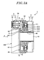
Fig. 3A is a view showing an example of the joint mechanism. -
Fig. 3B is a view showing a state in which a first unit and a second unit of the joint mechanism shown inFig. 3A are separated from each other. -
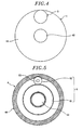
Fig. 4 is a view showing the positional relationship of the first unit and the second unit shown inFig. 3B , which are seen in a direction of arrow A inFig. 3A . -
Fig. 5 is a sectional view taken along line V-V inFig. 3A , showing a power delivery unit of the joint mechanism shown inFig. 3A . -
Fig. 6 is a view showing a modified example of the joint mechanism. -
Fig. 7 is a view showing a power delivery unit of the joint mechanism according to the modified example shown inFig. 6 . - An embodiment of a joint mechanism and a robot disclosed herein will now be described in detail with reference to the accompanying drawings. The present disclosure is not limited to the embodiment to be described below.
- First, a robot 1 in accordance with the present embodiment will be described with reference to
Fig. 1 . In the following description, an X-axis and a Y-axis orthogonal to each other are defined as being parallel to an installation surface (e.g., horizontal surface) of the robot 1. A Z-axis is defined as being perpendicular, i.e., normal, to the installation surface. - In the present embodiment, the robot 1 is, e.g., an articulated robot. As shown in
Fig. 1 , the robot 1 includes abase 11, abody unit 12 arranged on thebase 11, anarm unit 13 connected to thebody unit 12 and awrist unit 14 arranged at the tip end of thearm unit 13. - The
base 11 is fixed to an installation surface through aseat portion 11a. Thebody unit 12 is arranged on thebase 11 to horizontally rotate about a vertical axis (the Z-axis inFig. 1 ). Thebody unit 12 is horizontally rotated by the operation of amotor unit 20. - The
arm unit 13 connected to thebody unit 12 includes afirst arm 131 and asecond arm 132 as a plurality of links. Thefirst arm 131 and thesecond arm 132 are rotatably connected to each other through a joint unit. - Specifically, the
first arm 131 is connected to thebody unit 12 through afirst joint unit 2a to swing in the front-rear direction (the Y-direction). Thesecond arm 132 is connected to the tip end portion of thefirst arm 131 through asecond joint unit 2b to swing in the up-down direction (the Z-direction). The firstjoint unit 2a for swinging thefirst arm 131 is provided with afirst motor unit 21. The secondjoint unit 2b for swinging thesecond arm 132 is provided with asecond motor unit 22. - The
wrist unit 14 includes afirst wrist 141 and asecond wrist 142 as a plurality of links. Thefirst wrist 141 and thesecond wrist 142 are rotatably connected to each other through a joint unit provided with a below-mentionedjoint mechanism 3. That is to say, the robot 1 in accordance with the present embodiment has a structure in which a pair of links is connected to each other through thejoint mechanism 3. - Now, the
joint mechanism 3 of the joint unit employed in thewrist unit 14 will be described in detail with reference toFigs. 2A to 6 . - As shown in
Fig. 2A , thefirst wrist 141 and thesecond wrist 142 of thewrist unit 14 are rotatably connected to each other through a joint unit. Specifically, thefirst wrist 141 is formed into a bifurcated shape. The base end portion of thefirst wrist 141 is connected to the tip end portion of thesecond arm 132 to rotate about a rotation axis through athird joint unit 2c provided with thejoint mechanism 3. - The
second wrist 142 is connected to the tip end portion of thefirst wrist 141 through afourth joint unit 2d to swing about a swing axis in, e.g., the Z-direction inFig. 1 . Thesecond wrist 142 is connected to thefirst wrist 141 to rotate about a rotation axis by afifth joint unit 2e. Each of thethird joint unit 2c, thefourth joint unit 2d and thefifth joint unit 2e is formed into a hollow structure. Acable 82 including a hose extends through hollow portions of thethird joint unit 2c and thefifth joint unit 2e. Abrake unit 51 and anencoder unit 52, both of which will be described later, are disposed in a hollow portion of thefourth joint unit 2d. - First, description will be made on the
joint mechanisms 3 provided in the thirdjoint unit 2c and the fifthjoint unit 2e. That is to say, description will be made on thejoint mechanisms 3 arranged in the links (thefirst wrist 141 and the second wrist 142) serving as driven members and arranged in the joint units for rotating the links about their rotation axes. - As shown in
Fig. 3A , thejoint mechanism 3 includes afirst unit 4 in which amotor unit 41 and aspeed reducer 42 are coaxially arranged with respect to ahollow portion 43 formed by anarm frame 44 of the robot 1, through ahollow rotation shaft 46 as a first shaft. - The
joint mechanism 3 further includes asecond unit 5 in which thebrake unit 51 and theencoder unit 52 are coaxially arranged on arotation shaft 53 as a second shaft separated from the hollow rotation shaft 46 (the first shaft). Thejoint mechanism 3 still further includes afirst gear mechanism 6 as a power delivery unit arranged between the hollow rotation shaft 46 (the first shaft) and the rotation shaft 53 (the second shaft). - The
first unit 4 is attached to thearm frame 44 of the robot 1. Themotor unit 41 of thefirst unit 4 includes astator 411 attached to thearm frame 44 of the robot 1 and arotor 412 rotatably arranged with a predetermined gap left between thestator 411 and therotor 412. In the present embodiment, thehollow rotation shaft 46 is one-piece formed with therotor 412 of themotor unit 41 and is connected to thespeed reducer 42. Thus, the rotation of therotor 412 is delivered to thespeed reducer 42 through thehollow rotation shaft 46. Thehollow rotation shaft 46 need not be necessarily one-piece formed with therotor 412 but may be independently formed and unified with therotor 412. InFig. 3A ,reference symbol 413 designates a stator core.Reference symbol 414 designates a stator coil.Reference symbol 415 designates a rotor magnet. - In the meantime, the
speed reducer 42 is attached to thearm frame 44 and is arranged adjacent to themotor unit 41 at the opposite side from thesecond unit 5. Thespeed reducer 42 includes a specified gear set (not shown) arranged therein and reduces the power delivered from themotor unit 41 at a predetermined speed reduction ratio. With this configuration, it is possible to rotate the links as driven members (e.g., thefirst wrist 141 and the second wrist 142) at a desired speed, the links being arranged with thearm frame 44 interposed therebetween. - As mentioned above, the
motor unit 41 and thespeed reducer 42 of thefirst unit 4 have a hollow structure in which themotor unit 41 and thespeed reducer 42 are supported on thehollow portion 43 of thearm frame 44 through thehollow rotation shaft 46. Therefore, as shown inFigs. 2A and2B , a specifiedcable 82 can be arranged within thehollow portion 43 along the rotation axis direction. - On the other hand, the
second unit 5 is configured by coaxially arranging thebrake unit 51 and theencoder unit 52 on therotation shaft 53 as the second shaft extending in the longitudinal direction of acylindrical unit frame 54. As shown inFig. 3B , thesecond unit 5 is attached to oneend surface 441 of thearm frame 44 at the opposite side to thefirst unit 4, by bolts (not shown) as connecting members. InFig. 3B ,reference symbol 442 designates an attachment hole where thesecond unit 5 is to be attached. Thebrake unit 51 and theencoder unit 52 of thesecond unit 5 may be the conventional ones well-known in the art. - As shown in
Fig. 3A and4 , thesecond unit 5 is attached in a state in which the axis of therotation shaft 53 is radially offset with respect to thehollow rotation shaft 46 of thefirst unit 4. Specifically, in thejoint mechanism 3 in accordance with the present embodiment, thesecond unit 5 is made smaller in size than the first unit 4 (thesecond unit 5 has a diameter of one quarter of the diameter of thefirst unit 4 when seen in the axial direction of the hollow rotation shaft 46). A specifiedspace 100 is formed near the second unit 5 (Fig. 3A ). - As shown in
Fig. 2A , the fourthjoint unit 2d for enabling thesecond wrist 142 to swing in the up-down direction can be arranged in thespace 100. With this configuration, it is possible to reduce the longitudinal dimension of thewrist unit 14. As shown inFig. 2B , thesecond unit 5 of the fifthjoint unit 2e is arranged at the right side with respect to thehollow portion 43 of thearm frame 44. Therefore, a portion of the space 100 (seeFig. 3A ) can be used in passing thecable 81 therethrough. In the illustrated example, although thesecond unit 5 is offset to the right side with respect to thehollow portion 43 of thearm frame 44, thesecond unit 5 may be offset to the left side with respect to thehollow portion 43 of thearm frame 44. The remaining space may be used in passing thecable 81 therethrough. - The
first unit 4 and thesecond unit 5 are connected to each other by afirst gear mechanism 6 serving as the power delivery unit. That is to say, the power of themotor unit 41 is delivered through the first gear mechanism 6 (the power delivery unit). - The
first gear mechanism 6 includes a plurality of gears combined with each other at a predetermined gear ratio. As shown inFigs. 3A and5 , thefirst gear mechanism 6 in accordance with the present embodiment includes alarge gear 61 arranged in themotor unit 41 of thefirst unit 4 and asmall gear 62 arranged at the tip end of therotation shaft 53 of thesecond unit 5. Thelarge gear 61 is connected to the end surface of thehollow rotation shaft 46 by a fastening means, e.g., bolts (not shown). - As shown in
Figs. 3A and3B , thesmall gear 62 meshes with thelarge gear 61 so that thesecond unit 5 is attached to thefirst unit 4. Thelarge gear 61 and thesmall gear 62 are formed of spur gears and, therefore, can be easily moved in the axial direction. Thus, thesecond unit 5 can be easily attached to and removed from the first unit 4 (seeFig. 3B ). - As set forth above, the
joint mechanism 3 in accordance with the present embodiment includes thefirst unit 4, which has themotor unit 41 and thespeed reducer 42, and thesecond unit 5 which has thebrake unit 51 and theencoder unit 52. Thefirst unit 4 and thesecond unit 5 are detachably attached to each other. Thehollow rotation shaft 46 of themotor unit 41 of thefirst unit 4 and therotation shaft 53 of thesecond unit 5 are operatively connected by thefirst gear mechanism 6. - In the
joint mechanism 3 configured as above, thesecond unit 5 can be readily attached to and removed from thefirst unit 4. Accordingly, the maintainability of thebrake unit 51 and theencoder unit 52, which are required to be replaced more frequently than themotor unit 41 and thespeed reducer 42, can be improved as compared with the conventional joint mechanism. - As described above, the
large gear 61 is arranged in themotor unit 41 of thefirst unit 4, and thesmall gear 62 is arranged in therotation shaft 53 of thesecond unit 5. Thus, the rotation of themotor unit 41 can be delivered to therotation shaft 53 of thesecond unit 5 at an increased speed. - Accordingly, the power of the
motor unit 41 can be delivered to thebrake unit 51 at a reduced torque. For that reason, it is possible to employ a small and inexpensive brake structure. This contributes to the size reduction and the cost saving of the robot 1. - Since the rotation of the
motor unit 41 can be delivered to therotation shaft 53 of thesecond unit 5 at an increased speed, it is possible to use theencoder unit 52 having a low resolution. Therefore, just like thebrake unit 51, it is possible to reduce the cost of theencoder unit 52 and to accomplish the cost-effectiveness of the robot 1. - Next, a
joint mechanism 3d in accordance with a modified example provided in the fourthjoint unit 2d (seeFig. 2A ) that swingably connects the second wrist 142 (the link) to thefirst wrist 141 will be described with reference toFigs. 6 and7 . - The
joint mechanism 3d in accordance with the modified example is basically identical in configuration with thejoint mechanisms 3 provided in the thirdjoint unit 2c and the fifthjoint unit 2e. As shown inFigs. 2A to 3B , thejoint mechanism 3d includes afirst unit 4 having amotor unit 41 and aspeed reducer 42, and asecond unit 5 having abrake unit 51 and anencoder unit 52, and thefirst unit 4 and thesecond unit 5 are separable from each other. - In the
joint mechanism 3d in accordance with the present modified example, thesecond unit 5 is not attached to the outside of thefirst unit 4 but is arranged within thehollow portion 43 of thefirst unit 4. Specifically, in the fourthjoint unit 2d, there is no need to pass a cable or the like through thehollow portion 43, and thus thesecond unit 5 is accommodated within thehollow portion 43. The axis of thehollow portion 43 of thefirst unit 4 coincides with the axis of therotation shaft 53 of thesecond unit 5. - Since the
second unit 5 is arranged within thehollow portion 43 of thefirst unit 4 as mentioned above, asecond gear mechanism 7 shown inFig. 7 is used as a power delivery unit instead of thefirst gear mechanism 6. - Like the
first gear mechanism 6, thesecond gear mechanism 7 is composed of a plurality of gears combined with one another at a specified gear ratio. That is to say, as shown inFig. 7 , thesecond gear mechanism 7 includes aring gear 71, aninput gear 72 and anidle gear 73. - The
ring gear 71 is fixedly secured to the tip-end-side inner circumferential surface of thehollow rotation shaft 46 of thefirst unit 4. Theinput gear 72 is arranged at the tip end of therotation shaft 53 of thesecond unit 5. Theidle gear 73 is disposed between thering gear 71 and theinput gear 72. - With this configuration, the rotation of the
motor unit 41 is delivered to thering gear 71, theidle gear 73 and then theinput gear 72. In this case, the rotation of themotor unit 41 of thefirst unit 4 is delivered to therotation shaft 53 of thesecond unit 5 at an increased speed. Accordingly, in thejoint mechanism 3d of the fourthjoint unit 2d, it is possible to reduce the size of thebrake unit 51 and to reduce the resolution of theencoder unit 52. Moreover, it is possible to accomplish the cost-effectiveness of the robot 1. - As described above, in the
joint mechanisms 3 of the thirdjoint unit 2c and the fifthjoint unit 2e of thewrist unit 14 according to the present embodiment, the interior of thehollow portion 43 of thefirst unit 4 can be used as a space through which a cable or the like passes. In thejoint mechanism 3d of the fourthjoint unit 2d, the interior of thehollow portion 43 can be used as an accommodation portion for thesecond unit 5. - The basic structure of the
joint mechanisms joint mechanism 3 having a hollow structure through which thecable 82 or the like can pass and thejoint mechanism 3d having a hollow structure within which the second unit 5d is accommodated as in the modified example, it is possible to use common parts. - In the present embodiment in which the
second unit 5 is externally installed, thesecond unit 5 is attached to oneend surface 441 of thearm frame 44. However, in the configuration in which thesecond unit 5 is installed outside thefirst unit 4, for example, thesecond unit 5 may be fitted into theattachment hole 442 formed on the oneend surface 441 of thearm frame 44 and attached to the frame of themotor unit 41 of thefirst unit 4. - In the aforementioned embodiment and the modified example, the gear mechanisms are used as the power delivery units. As an alternative example, the power delivery unit may be formed of pulleys and a belt.
- In the present embodiment and the modified example, there has been shown an example in which the
joint mechanisms wrist unit 14. However, thejoint mechanisms - It should be understood by those skilled in the art that various modifications, combinations, sub-combinations and alterations may occur depending on design requirements and other factors insofar as they are within the scope of the appended claims or the equivalents thereof.
Claims (8)
- A joint mechanism, comprising:a first unit in which a motor unit and a speed reducer are coaxially arranged on a hollow first shaft;a second unit in which a brake unit and an encoder unit are coaxially arranged on a second shaft separated from the first shaft; anda power delivery unit configured to interconnect the first unit and the second unit.
- The joint mechanism of claim 1, wherein the power delivery unit includes a plurality of gears combined with one another.
- The joint mechanism of claim 1 or 2, wherein the power delivery unit is configured to deliver rotation of the first shaft to the second shaft at an increased speed.
- The joint mechanism of any one of claims 1 to 3, wherein the second shaft has an axis offset with respect to the first shaft, and the second unit is externally attached to the first unit.
- The joint mechanism of any one of claims 1 to 3, wherein the second unit is arranged within the first shaft of the first unit.
- The joint mechanism of claim 1, wherein the power delivery unit includes pulleys and a belt.
- A robot comprising the joint mechanism of any one of claims 1 to 6.
- The robot of claim 7, further comprising at least one pair of links interconnected by the joint mechanism.
Applications Claiming Priority (1)
| Application Number | Priority Date | Filing Date | Title |
|---|---|---|---|
| JP2013024957A JP5573987B1 (en) | 2013-02-12 | 2013-02-12 | Joint mechanism and robot |
Publications (2)
| Publication Number | Publication Date |
|---|---|
| EP2764959A1 true EP2764959A1 (en) | 2014-08-13 |
| EP2764959B1 EP2764959B1 (en) | 2015-03-11 |
Family
ID=50101702
Family Applications (1)
| Application Number | Title | Priority Date | Filing Date |
|---|---|---|---|
| EP14154077.3A Not-in-force EP2764959B1 (en) | 2013-02-12 | 2014-02-06 | Joint mechanism and robot |
Country Status (6)
| Country | Link |
|---|---|
| US (1) | US20140224057A1 (en) |
| EP (1) | EP2764959B1 (en) |
| JP (1) | JP5573987B1 (en) |
| KR (1) | KR20140101679A (en) |
| CN (1) | CN103978495A (en) |
| IN (1) | IN2014CH00634A (en) |
Cited By (4)
| Publication number | Priority date | Publication date | Assignee | Title |
|---|---|---|---|---|
| EP3046236A1 (en) * | 2015-01-15 | 2016-07-20 | Kabushiki Kaisha Yaskawa Denki | Electric rotating machine |
| EP3050680A1 (en) * | 2015-01-29 | 2016-08-03 | Kabushiki Kaisha Yaskawa Denki | Robot |
| EP3050681A1 (en) * | 2015-01-29 | 2016-08-03 | Kabushiki Kaisha Yaskawa Denki | Robot |
| US11376729B2 (en) | 2019-01-29 | 2022-07-05 | Fanuc Corporation | Robot |
Families Citing this family (17)
| Publication number | Priority date | Publication date | Assignee | Title |
|---|---|---|---|---|
| DE102013216449A1 (en) * | 2013-08-20 | 2015-02-26 | Kuka Roboter Gmbh | Industrial robot with at least one drive |
| USD774578S1 (en) | 2014-04-09 | 2016-12-20 | Fanuc Corporation | Industrial robot |
| USD774580S1 (en) | 2014-09-26 | 2016-12-20 | Fanuc Corporation | Industrial robot |
| USD774579S1 (en) | 2014-09-26 | 2016-12-20 | Fanuc Corporation | Industrial robot |
| USD766348S1 (en) * | 2014-10-23 | 2016-09-13 | Hon Hai Precision Industry Co., Ltd. | Robot |
| JP6055018B2 (en) * | 2015-04-09 | 2016-12-27 | ファナック株式会社 | Robot joint structure with motor and reducer |
| KR101643392B1 (en) * | 2015-05-19 | 2016-07-27 | 주식회사 민트로봇 | Hollow Type Actuator Having Parallel Structure |
| DE102016004787B4 (en) * | 2016-04-20 | 2023-02-02 | Franka Emika Gmbh | Driving device for a robot and method for its manufacture |
| KR101838091B1 (en) * | 2016-05-30 | 2018-03-13 | 한국기계연구원 | Compliant type driving module |
| USD802041S1 (en) * | 2017-04-27 | 2017-11-07 | Engineering Services Inc | Robotic arm |
| US10022861B1 (en) | 2017-04-27 | 2018-07-17 | Engineering Services Inc. | Two joint module and arm using same |
| USD890238S1 (en) * | 2018-03-02 | 2020-07-14 | Abb Schweiz Ag | Joint for an industrial robot |
| USD929481S1 (en) * | 2018-04-27 | 2021-08-31 | Staubli Faverges | Industrial robots |
| TWI663813B (en) | 2018-11-28 | 2019-06-21 | 財團法人工業技術研究院 | Output torque caculation device and caculation method thereof |
| JP6867421B2 (en) * | 2019-01-23 | 2021-04-28 | ファナック株式会社 | Robot seal structure and robot |
| CN114423572B (en) | 2019-09-25 | 2024-09-10 | 雅马哈发动机株式会社 | Vertical multi-jointed robot |
| JP7469035B2 (en) * | 2019-12-12 | 2024-04-16 | ファナック株式会社 | Robot joint structure |
Citations (5)
| Publication number | Priority date | Publication date | Assignee | Title |
|---|---|---|---|---|
| JPS61131891A (en) * | 1984-11-29 | 1986-06-19 | 三菱重工業株式会社 | Rotary joint mechanism |
| US5293107A (en) * | 1993-02-24 | 1994-03-08 | Fanuc Robotics North America, Inc. | Motorized rotary joint and method of constructing a modular robot utilizing same |
| FR2771153A1 (en) * | 1997-11-19 | 1999-05-21 | Staubli Sa Ets | Epicycloidal or cycloidal reducer for robot articulation |
| US20070138991A1 (en) * | 2003-03-05 | 2007-06-21 | Mitsubishi Denki Kabushiki Kaisha | Pivoting apparatus of industrial robot |
| EP2264865A2 (en) * | 2009-06-19 | 2010-12-22 | Kabushiki Kaisha Yaskawa Denki | Hollow actuator with build-in reduction gear |
Family Cites Families (5)
| Publication number | Priority date | Publication date | Assignee | Title |
|---|---|---|---|---|
| JPS61129521A (en) * | 1984-11-29 | 1986-06-17 | Mitsubishi Heavy Ind Ltd | Detecting device of absolute position |
| JPS61288985A (en) * | 1985-06-14 | 1986-12-19 | 株式会社日立製作所 | Robot joint structure |
| JPS6228184A (en) * | 1985-07-30 | 1987-02-06 | ぺんてる株式会社 | Inertial driving arm type robot |
| US4678952A (en) * | 1985-08-13 | 1987-07-07 | Intelledex Incorporated | Sealed joint for a robot and the like |
| JP3656328B2 (en) * | 1996-07-11 | 2005-06-08 | 日産自動車株式会社 | Positioning assist arm |
-
2013
- 2013-02-12 JP JP2013024957A patent/JP5573987B1/en not_active Expired - Fee Related
-
2014
- 2014-02-06 EP EP14154077.3A patent/EP2764959B1/en not_active Not-in-force
- 2014-02-07 KR KR1020140014289A patent/KR20140101679A/en not_active Ceased
- 2014-02-07 US US14/174,851 patent/US20140224057A1/en not_active Abandoned
- 2014-02-11 CN CN201410047360.7A patent/CN103978495A/en active Pending
- 2014-02-11 IN IN634CH2014 patent/IN2014CH00634A/en unknown
Patent Citations (6)
| Publication number | Priority date | Publication date | Assignee | Title |
|---|---|---|---|---|
| JPS61131891A (en) * | 1984-11-29 | 1986-06-19 | 三菱重工業株式会社 | Rotary joint mechanism |
| US5293107A (en) * | 1993-02-24 | 1994-03-08 | Fanuc Robotics North America, Inc. | Motorized rotary joint and method of constructing a modular robot utilizing same |
| FR2771153A1 (en) * | 1997-11-19 | 1999-05-21 | Staubli Sa Ets | Epicycloidal or cycloidal reducer for robot articulation |
| US20070138991A1 (en) * | 2003-03-05 | 2007-06-21 | Mitsubishi Denki Kabushiki Kaisha | Pivoting apparatus of industrial robot |
| EP2264865A2 (en) * | 2009-06-19 | 2010-12-22 | Kabushiki Kaisha Yaskawa Denki | Hollow actuator with build-in reduction gear |
| JP2011024406A (en) | 2009-06-19 | 2011-02-03 | Yaskawa Electric Corp | Hollow actuator with built-in reduction gear |
Cited By (4)
| Publication number | Priority date | Publication date | Assignee | Title |
|---|---|---|---|---|
| EP3046236A1 (en) * | 2015-01-15 | 2016-07-20 | Kabushiki Kaisha Yaskawa Denki | Electric rotating machine |
| EP3050680A1 (en) * | 2015-01-29 | 2016-08-03 | Kabushiki Kaisha Yaskawa Denki | Robot |
| EP3050681A1 (en) * | 2015-01-29 | 2016-08-03 | Kabushiki Kaisha Yaskawa Denki | Robot |
| US11376729B2 (en) | 2019-01-29 | 2022-07-05 | Fanuc Corporation | Robot |
Also Published As
| Publication number | Publication date |
|---|---|
| JP2014151412A (en) | 2014-08-25 |
| JP5573987B1 (en) | 2014-08-20 |
| CN103978495A (en) | 2014-08-13 |
| EP2764959B1 (en) | 2015-03-11 |
| KR20140101679A (en) | 2014-08-20 |
| IN2014CH00634A (en) | 2015-04-10 |
| US20140224057A1 (en) | 2014-08-14 |
Similar Documents
| Publication | Publication Date | Title |
|---|---|---|
| EP2764959B1 (en) | Joint mechanism and robot | |
| US20140224058A1 (en) | Joint mechanism and robot | |
| US8235856B2 (en) | Gear device and turning portion structure of industrial robot using the gear device | |
| CN101273216B (en) | Hollow reduction gear | |
| US9095982B2 (en) | Drive apparatus and robot | |
| JP5746093B2 (en) | Industrial robot wrist device | |
| CN108626320A (en) | Flexible engagement gear device | |
| CN102947049A (en) | Spindle unit, table unit, and machine tool | |
| EP2740970A1 (en) | Composite drive device and robot | |
| JP2016203758A (en) | Rear wheel steering device of vehicle | |
| JP7479355B2 (en) | Mechanical reducer and geared motor using the same | |
| CN102756707A (en) | Buckle adjuster for safety belt system of vehicle | |
| CN110230664A (en) | Gear unit and speed reducer | |
| JP6632430B2 (en) | Robot deceleration transmission | |
| CN105805234A (en) | Reducer, and vertically intersecting gear motor having same | |
| JP2023019883A5 (en) | ||
| CN116276948A (en) | Method for changing size of movement range of wrist part of robot and method for manufacturing robot | |
| JP2008025846A (en) | Turning part structure for robots, etc. | |
| CN207548757U (en) | Modular deceleration device and planar multiple-articulation robot | |
| CN107877504B (en) | Modular speed reducer and planar multi-joint robot | |
| CN203880018U (en) | Reduction box for door driving and driving device | |
| JP2008062377A (en) | Turning part structure for robots, etc. | |
| JP2008023711A (en) | Turning part structure for robots, etc. | |
| KR100626750B1 (en) | Reduction gear having hypoid gear | |
| JP2009183033A (en) | Actuator and vehicle lamp device |
Legal Events
| Date | Code | Title | Description |
|---|---|---|---|
| PUAI | Public reference made under article 153(3) epc to a published international application that has entered the european phase |
Free format text: ORIGINAL CODE: 0009012 |
|
| 17P | Request for examination filed |
Effective date: 20140206 |
|
| AK | Designated contracting states |
Kind code of ref document: A1 Designated state(s): AL AT BE BG CH CY CZ DE DK EE ES FI FR GB GR HR HU IE IS IT LI LT LU LV MC MK MT NL NO PL PT RO RS SE SI SK SM TR |
|
| AX | Request for extension of the european patent |
Extension state: BA ME |
|
| R17P | Request for examination filed (corrected) |
Effective date: 20140722 |
|
| RBV | Designated contracting states (corrected) |
Designated state(s): AL AT BE BG CH CY CZ DE DK EE ES FI FR GB GR HR HU IE IS IT LI LT LU LV MC MK MT NL NO PL PT RO RS SE SI SK SM TR |
|
| GRAP | Despatch of communication of intention to grant a patent |
Free format text: ORIGINAL CODE: EPIDOSNIGR1 |
|
| INTG | Intention to grant announced |
Effective date: 20141009 |
|
| GRAS | Grant fee paid |
Free format text: ORIGINAL CODE: EPIDOSNIGR3 |
|
| GRAA | (expected) grant |
Free format text: ORIGINAL CODE: 0009210 |
|
| AK | Designated contracting states |
Kind code of ref document: B1 Designated state(s): AL AT BE BG CH CY CZ DE DK EE ES FI FR GB GR HR HU IE IS IT LI LT LU LV MC MK MT NL NO PL PT RO RS SE SI SK SM TR |
|
| REG | Reference to a national code |
Ref country code: GB Ref legal event code: FG4D |
|
| REG | Reference to a national code |
Ref country code: CH Ref legal event code: EP |
|
| REG | Reference to a national code |
Ref country code: IE Ref legal event code: FG4D |
|
| REG | Reference to a national code |
Ref country code: AT Ref legal event code: REF Ref document number: 715056 Country of ref document: AT Kind code of ref document: T Effective date: 20150415 |
|
| REG | Reference to a national code |
Ref country code: DE Ref legal event code: R096 Ref document number: 602014000004 Country of ref document: DE Effective date: 20150423 |
|
| REG | Reference to a national code |
Ref country code: NL Ref legal event code: VDEP Effective date: 20150311 |
|
| REG | Reference to a national code |
Ref country code: NL Ref legal event code: VDEP Effective date: 20150311 |
|
| PG25 | Lapsed in a contracting state [announced via postgrant information from national office to epo] |
Ref country code: FI Free format text: LAPSE BECAUSE OF FAILURE TO SUBMIT A TRANSLATION OF THE DESCRIPTION OR TO PAY THE FEE WITHIN THE PRESCRIBED TIME-LIMIT Effective date: 20150311 Ref country code: NO Free format text: LAPSE BECAUSE OF FAILURE TO SUBMIT A TRANSLATION OF THE DESCRIPTION OR TO PAY THE FEE WITHIN THE PRESCRIBED TIME-LIMIT Effective date: 20150611 Ref country code: ES Free format text: LAPSE BECAUSE OF FAILURE TO SUBMIT A TRANSLATION OF THE DESCRIPTION OR TO PAY THE FEE WITHIN THE PRESCRIBED TIME-LIMIT Effective date: 20150311 Ref country code: HR Free format text: LAPSE BECAUSE OF FAILURE TO SUBMIT A TRANSLATION OF THE DESCRIPTION OR TO PAY THE FEE WITHIN THE PRESCRIBED TIME-LIMIT Effective date: 20150311 Ref country code: LT Free format text: LAPSE BECAUSE OF FAILURE TO SUBMIT A TRANSLATION OF THE DESCRIPTION OR TO PAY THE FEE WITHIN THE PRESCRIBED TIME-LIMIT Effective date: 20150311 Ref country code: SE Free format text: LAPSE BECAUSE OF FAILURE TO SUBMIT A TRANSLATION OF THE DESCRIPTION OR TO PAY THE FEE WITHIN THE PRESCRIBED TIME-LIMIT Effective date: 20150311 |
|
| REG | Reference to a national code |
Ref country code: AT Ref legal event code: MK05 Ref document number: 715056 Country of ref document: AT Kind code of ref document: T Effective date: 20150311 |
|
| REG | Reference to a national code |
Ref country code: LT Ref legal event code: MG4D |
|
| PG25 | Lapsed in a contracting state [announced via postgrant information from national office to epo] |
Ref country code: GR Free format text: LAPSE BECAUSE OF FAILURE TO SUBMIT A TRANSLATION OF THE DESCRIPTION OR TO PAY THE FEE WITHIN THE PRESCRIBED TIME-LIMIT Effective date: 20150612 Ref country code: LV Free format text: LAPSE BECAUSE OF FAILURE TO SUBMIT A TRANSLATION OF THE DESCRIPTION OR TO PAY THE FEE WITHIN THE PRESCRIBED TIME-LIMIT Effective date: 20150311 Ref country code: RS Free format text: LAPSE BECAUSE OF FAILURE TO SUBMIT A TRANSLATION OF THE DESCRIPTION OR TO PAY THE FEE WITHIN THE PRESCRIBED TIME-LIMIT Effective date: 20150311 |
|
| PG25 | Lapsed in a contracting state [announced via postgrant information from national office to epo] |
Ref country code: NL Free format text: LAPSE BECAUSE OF FAILURE TO SUBMIT A TRANSLATION OF THE DESCRIPTION OR TO PAY THE FEE WITHIN THE PRESCRIBED TIME-LIMIT Effective date: 20150311 |
|
| PG25 | Lapsed in a contracting state [announced via postgrant information from national office to epo] |
Ref country code: PT Free format text: LAPSE BECAUSE OF FAILURE TO SUBMIT A TRANSLATION OF THE DESCRIPTION OR TO PAY THE FEE WITHIN THE PRESCRIBED TIME-LIMIT Effective date: 20150713 Ref country code: CZ Free format text: LAPSE BECAUSE OF FAILURE TO SUBMIT A TRANSLATION OF THE DESCRIPTION OR TO PAY THE FEE WITHIN THE PRESCRIBED TIME-LIMIT Effective date: 20150311 Ref country code: EE Free format text: LAPSE BECAUSE OF FAILURE TO SUBMIT A TRANSLATION OF THE DESCRIPTION OR TO PAY THE FEE WITHIN THE PRESCRIBED TIME-LIMIT Effective date: 20150311 Ref country code: RO Free format text: LAPSE BECAUSE OF FAILURE TO SUBMIT A TRANSLATION OF THE DESCRIPTION OR TO PAY THE FEE WITHIN THE PRESCRIBED TIME-LIMIT Effective date: 20150311 Ref country code: SK Free format text: LAPSE BECAUSE OF FAILURE TO SUBMIT A TRANSLATION OF THE DESCRIPTION OR TO PAY THE FEE WITHIN THE PRESCRIBED TIME-LIMIT Effective date: 20150311 |
|
| PG25 | Lapsed in a contracting state [announced via postgrant information from national office to epo] |
Ref country code: PL Free format text: LAPSE BECAUSE OF FAILURE TO SUBMIT A TRANSLATION OF THE DESCRIPTION OR TO PAY THE FEE WITHIN THE PRESCRIBED TIME-LIMIT Effective date: 20150311 Ref country code: AT Free format text: LAPSE BECAUSE OF FAILURE TO SUBMIT A TRANSLATION OF THE DESCRIPTION OR TO PAY THE FEE WITHIN THE PRESCRIBED TIME-LIMIT Effective date: 20150311 Ref country code: IS Free format text: LAPSE BECAUSE OF FAILURE TO SUBMIT A TRANSLATION OF THE DESCRIPTION OR TO PAY THE FEE WITHIN THE PRESCRIBED TIME-LIMIT Effective date: 20150711 |
|
| REG | Reference to a national code |
Ref country code: DE Ref legal event code: R097 Ref document number: 602014000004 Country of ref document: DE |
|
| PG25 | Lapsed in a contracting state [announced via postgrant information from national office to epo] |
Ref country code: IT Free format text: LAPSE BECAUSE OF FAILURE TO SUBMIT A TRANSLATION OF THE DESCRIPTION OR TO PAY THE FEE WITHIN THE PRESCRIBED TIME-LIMIT Effective date: 20150311 |
|
| PLBE | No opposition filed within time limit |
Free format text: ORIGINAL CODE: 0009261 |
|
| STAA | Information on the status of an ep patent application or granted ep patent |
Free format text: STATUS: NO OPPOSITION FILED WITHIN TIME LIMIT |
|
| PG25 | Lapsed in a contracting state [announced via postgrant information from national office to epo] |
Ref country code: DK Free format text: LAPSE BECAUSE OF FAILURE TO SUBMIT A TRANSLATION OF THE DESCRIPTION OR TO PAY THE FEE WITHIN THE PRESCRIBED TIME-LIMIT Effective date: 20150311 |
|
| 26N | No opposition filed |
Effective date: 20151214 |
|
| PG25 | Lapsed in a contracting state [announced via postgrant information from national office to epo] |
Ref country code: SI Free format text: LAPSE BECAUSE OF FAILURE TO SUBMIT A TRANSLATION OF THE DESCRIPTION OR TO PAY THE FEE WITHIN THE PRESCRIBED TIME-LIMIT Effective date: 20150311 |
|
| PG25 | Lapsed in a contracting state [announced via postgrant information from national office to epo] |
Ref country code: BE Free format text: LAPSE BECAUSE OF NON-PAYMENT OF DUE FEES Effective date: 20160229 |
|
| PG25 | Lapsed in a contracting state [announced via postgrant information from national office to epo] |
Ref country code: BE Free format text: LAPSE BECAUSE OF FAILURE TO SUBMIT A TRANSLATION OF THE DESCRIPTION OR TO PAY THE FEE WITHIN THE PRESCRIBED TIME-LIMIT Effective date: 20150311 |
|
| REG | Reference to a national code |
Ref country code: DE Ref legal event code: R119 Ref document number: 602014000004 Country of ref document: DE |
|
| PG25 | Lapsed in a contracting state [announced via postgrant information from national office to epo] |
Ref country code: LU Free format text: LAPSE BECAUSE OF FAILURE TO SUBMIT A TRANSLATION OF THE DESCRIPTION OR TO PAY THE FEE WITHIN THE PRESCRIBED TIME-LIMIT Effective date: 20160206 Ref country code: MC Free format text: LAPSE BECAUSE OF FAILURE TO SUBMIT A TRANSLATION OF THE DESCRIPTION OR TO PAY THE FEE WITHIN THE PRESCRIBED TIME-LIMIT Effective date: 20150311 |
|
| REG | Reference to a national code |
Ref country code: FR Ref legal event code: ST Effective date: 20161028 |
|
| REG | Reference to a national code |
Ref country code: IE Ref legal event code: MM4A |
|
| PG25 | Lapsed in a contracting state [announced via postgrant information from national office to epo] |
Ref country code: FR Free format text: LAPSE BECAUSE OF NON-PAYMENT OF DUE FEES Effective date: 20160229 Ref country code: DE Free format text: LAPSE BECAUSE OF NON-PAYMENT OF DUE FEES Effective date: 20160901 Ref country code: IE Free format text: LAPSE BECAUSE OF NON-PAYMENT OF DUE FEES Effective date: 20160206 |
|
| PG25 | Lapsed in a contracting state [announced via postgrant information from national office to epo] |
Ref country code: MT Free format text: LAPSE BECAUSE OF FAILURE TO SUBMIT A TRANSLATION OF THE DESCRIPTION OR TO PAY THE FEE WITHIN THE PRESCRIBED TIME-LIMIT Effective date: 20150311 |
|
| REG | Reference to a national code |
Ref country code: CH Ref legal event code: PL |
|
| PG25 | Lapsed in a contracting state [announced via postgrant information from national office to epo] |
Ref country code: LI Free format text: LAPSE BECAUSE OF NON-PAYMENT OF DUE FEES Effective date: 20170228 Ref country code: CH Free format text: LAPSE BECAUSE OF NON-PAYMENT OF DUE FEES Effective date: 20170228 |
|
| PG25 | Lapsed in a contracting state [announced via postgrant information from national office to epo] |
Ref country code: SM Free format text: LAPSE BECAUSE OF FAILURE TO SUBMIT A TRANSLATION OF THE DESCRIPTION OR TO PAY THE FEE WITHIN THE PRESCRIBED TIME-LIMIT Effective date: 20150311 Ref country code: CY Free format text: LAPSE BECAUSE OF FAILURE TO SUBMIT A TRANSLATION OF THE DESCRIPTION OR TO PAY THE FEE WITHIN THE PRESCRIBED TIME-LIMIT Effective date: 20150311 Ref country code: HU Free format text: LAPSE BECAUSE OF FAILURE TO SUBMIT A TRANSLATION OF THE DESCRIPTION OR TO PAY THE FEE WITHIN THE PRESCRIBED TIME-LIMIT; INVALID AB INITIO Effective date: 20140206 |
|
| PG25 | Lapsed in a contracting state [announced via postgrant information from national office to epo] |
Ref country code: TR Free format text: LAPSE BECAUSE OF FAILURE TO SUBMIT A TRANSLATION OF THE DESCRIPTION OR TO PAY THE FEE WITHIN THE PRESCRIBED TIME-LIMIT Effective date: 20150311 Ref country code: MT Free format text: LAPSE BECAUSE OF FAILURE TO SUBMIT A TRANSLATION OF THE DESCRIPTION OR TO PAY THE FEE WITHIN THE PRESCRIBED TIME-LIMIT Effective date: 20160229 Ref country code: MK Free format text: LAPSE BECAUSE OF FAILURE TO SUBMIT A TRANSLATION OF THE DESCRIPTION OR TO PAY THE FEE WITHIN THE PRESCRIBED TIME-LIMIT Effective date: 20150311 |
|
| PG25 | Lapsed in a contracting state [announced via postgrant information from national office to epo] |
Ref country code: BG Free format text: LAPSE BECAUSE OF FAILURE TO SUBMIT A TRANSLATION OF THE DESCRIPTION OR TO PAY THE FEE WITHIN THE PRESCRIBED TIME-LIMIT Effective date: 20150311 |
|
| GBPC | Gb: european patent ceased through non-payment of renewal fee |
Effective date: 20180206 |
|
| PG25 | Lapsed in a contracting state [announced via postgrant information from national office to epo] |
Ref country code: AL Free format text: LAPSE BECAUSE OF FAILURE TO SUBMIT A TRANSLATION OF THE DESCRIPTION OR TO PAY THE FEE WITHIN THE PRESCRIBED TIME-LIMIT Effective date: 20150311 |
|
| PG25 | Lapsed in a contracting state [announced via postgrant information from national office to epo] |
Ref country code: GB Free format text: LAPSE BECAUSE OF NON-PAYMENT OF DUE FEES Effective date: 20180206 |