EP2764246B1 - Peristaltic pump - Google Patents
Peristaltic pump Download PDFInfo
- Publication number
- EP2764246B1 EP2764246B1 EP12759778.9A EP12759778A EP2764246B1 EP 2764246 B1 EP2764246 B1 EP 2764246B1 EP 12759778 A EP12759778 A EP 12759778A EP 2764246 B1 EP2764246 B1 EP 2764246B1
- Authority
- EP
- European Patent Office
- Prior art keywords
- tube
- squeeze
- peristaltic pump
- pump
- exendin
- Prior art date
- Legal status (The legal status is an assumption and is not a legal conclusion. Google has not performed a legal analysis and makes no representation as to the accuracy of the status listed.)
- Active
Links
Images



Classifications
-
- A—HUMAN NECESSITIES
- A61—MEDICAL OR VETERINARY SCIENCE; HYGIENE
- A61M—DEVICES FOR INTRODUCING MEDIA INTO, OR ONTO, THE BODY; DEVICES FOR TRANSDUCING BODY MEDIA OR FOR TAKING MEDIA FROM THE BODY; DEVICES FOR PRODUCING OR ENDING SLEEP OR STUPOR
- A61M5/00—Devices for bringing media into the body in a subcutaneous, intra-vascular or intramuscular way; Accessories therefor, e.g. filling or cleaning devices, arm-rests
- A61M5/14—Infusion devices, e.g. infusing by gravity; Blood infusion; Accessories therefor
- A61M5/142—Pressure infusion, e.g. using pumps
- A61M5/14212—Pumping with an aspiration and an expulsion action
- A61M5/14228—Pumping with an aspiration and an expulsion action with linear peristaltic action, i.e. comprising at least three pressurising members or a helical member
-
- A—HUMAN NECESSITIES
- A61—MEDICAL OR VETERINARY SCIENCE; HYGIENE
- A61M—DEVICES FOR INTRODUCING MEDIA INTO, OR ONTO, THE BODY; DEVICES FOR TRANSDUCING BODY MEDIA OR FOR TAKING MEDIA FROM THE BODY; DEVICES FOR PRODUCING OR ENDING SLEEP OR STUPOR
- A61M5/00—Devices for bringing media into the body in a subcutaneous, intra-vascular or intramuscular way; Accessories therefor, e.g. filling or cleaning devices, arm-rests
- A61M5/14—Infusion devices, e.g. infusing by gravity; Blood infusion; Accessories therefor
- A61M5/158—Needles for infusions; Accessories therefor, e.g. for inserting infusion needles, or for holding them on the body
-
- F—MECHANICAL ENGINEERING; LIGHTING; HEATING; WEAPONS; BLASTING
- F04—POSITIVE - DISPLACEMENT MACHINES FOR LIQUIDS; PUMPS FOR LIQUIDS OR ELASTIC FLUIDS
- F04B—POSITIVE-DISPLACEMENT MACHINES FOR LIQUIDS; PUMPS
- F04B43/00—Machines, pumps, or pumping installations having flexible working members
- F04B43/0009—Special features
- F04B43/0054—Special features particularities of the flexible members
- F04B43/0072—Special features particularities of the flexible members of tubular flexible members
-
- F—MECHANICAL ENGINEERING; LIGHTING; HEATING; WEAPONS; BLASTING
- F04—POSITIVE - DISPLACEMENT MACHINES FOR LIQUIDS; PUMPS FOR LIQUIDS OR ELASTIC FLUIDS
- F04B—POSITIVE-DISPLACEMENT MACHINES FOR LIQUIDS; PUMPS
- F04B43/00—Machines, pumps, or pumping installations having flexible working members
- F04B43/12—Machines, pumps, or pumping installations having flexible working members having peristaltic action
- F04B43/1253—Machines, pumps, or pumping installations having flexible working members having peristaltic action by using two or more rollers as squeezing elements, the rollers moving on an arc of a circle during squeezing
-
- F—MECHANICAL ENGINEERING; LIGHTING; HEATING; WEAPONS; BLASTING
- F04—POSITIVE - DISPLACEMENT MACHINES FOR LIQUIDS; PUMPS FOR LIQUIDS OR ELASTIC FLUIDS
- F04B—POSITIVE-DISPLACEMENT MACHINES FOR LIQUIDS; PUMPS
- F04B43/00—Machines, pumps, or pumping installations having flexible working members
- F04B43/12—Machines, pumps, or pumping installations having flexible working members having peristaltic action
- F04B43/1253—Machines, pumps, or pumping installations having flexible working members having peristaltic action by using two or more rollers as squeezing elements, the rollers moving on an arc of a circle during squeezing
- F04B43/1284—Means for pushing the backing-plate against the tubular flexible member
Definitions
- the present disclosure relates to a peristaltic pump.
- Peristaltic pumps are configured to transport a material in a tube by squeezing the tube.
- Peristaltic pumps are known, for example, from the documents DE 10246469 A1 and DE 19729612 A1 .
- a further peristaltic pump according to the preamble of claim 1 is known from document GB 979 330 .
- the pump therein is a highly complex system and will be expensive to manufacture and prone to mechanical fault due to the large number of intricate parts.
- the present invention provides a peristaltic pump, comprising a tube for transporting a material, wherein the tube is arranged along a longitudinal axis, a pump head configured to cause a squeezing of the tube, wherein the pump head is rotatable about a rotation axis, wherein the pump head comprises at least one squeeze member for squeezing the tube, and a support member, characterised in that the support member comprises a slot for supporting the at least one squeeze member, the slot extending in a radial direction relative to the rotation axis, such that a movement of the at least one squeeze member in a radial direction is enabled.
- the peristaltic pump may be configured to be applied for medical use.
- the peristaltic pump is configured to transport a medicament, for example a fluid medicament.
- the pump may be used in the field of micro fluidics.
- the peristaltic pump may be configured to dispense small amounts of fluids.
- the pump may be used for a transporting a highly sensitive material.
- the material to be transported may be a medicament, for example insulin.
- the peristaltic pump may be used as a drug delivery device.
- the peristaltic pump may comprise a receptacle.
- the receptacle may be configured to receive a cartridge or container holding the material to be transported.
- the tube is arranged along the longitudinal axis at least in a section of the tube which is configured to be squeezed for transporting the material.
- the tube is arranged along the longitudinal axis along its entire length.
- the tube is free of curved sections.
- the tube may be free of U-shaped sections.
- the pump is configured such that the material is transported in a transport direction.
- the transport direction is parallel to the longitudinal axis.
- the pump head causes a squeezing of the tube along the longitudinal axis of the tube, in particular along the transport direction.
- a transport of the material in the transport direction may be caused.
- the pump head may be configured such that a squeezed patch of the tube moves along the longitudinal axis. This may lead to an overpressure in the tube in front of the squeezed patch, which may lead to a movement of the material in the transport direction.
- the rotation axis of the pump head is perpendicular to the longitudinal axis.
- a compact size of the peristaltic pump may be achieved, because the pump head may have a small dimension in direction of the longitudinal axis.
- the pump head comprises at least one squeeze member for squeezing the tube.
- the squeeze member may be configured to be in mechanical contact with the tube for squeezing the tube.
- the squeeze member may be configured to close the tube at least at a particular time when squeezing the tube.
- the squeeze member squeezes the tube in a section of the tube running along the longitudinal axis. The section may run from a first position at the tube to a second position at the tube.
- the squeeze member squeezes the tube continuously from the first position to the second position and thereby moves the squeezed patch from the first position to the second position.
- the peristaltic pump is configured such that the squeeze member is enabled to roll off on the tube when squeezing the tube.
- the friction force between the squeeze member and the tube may be a rolling friction force, which is smaller than a sliding friction force.
- the squeeze member may comprise a spherical or cylindrical member, for example a ball or a roller.
- the pump head is configured to be operated at a constant driving speed.
- a constant, nearly shock free pumping may be achieved with a low variation of a pumping pressure.
- a high dosing accuracy may be achieved.
- the pump head comprises a support member for supporting the squeeze member.
- the support member rotates, in particular rotates about the rotation axis of the pump head.
- the squeeze member is supported by the support member such that a rotation of the squeeze member relative to the support member is enabled.
- the squeeze member may be rotatable relative to the support member about a further rotation axis, arranged in a distance from the rotation axis of the pump head.
- the further rotation axis may run through the center of the squeeze member.
- the further rotation axis may be parallel to the rotation axis of the pump head.
- the squeeze member is rotatable both about the rotation axis of the pump head and about the further rotation axis.
- the support member may comprise a disk-like shape.
- the squeeze member may be located near an outer perimeter of the support member.
- the squeeze member may be supported on the support member by a shaft.
- the shaft may run through the squeeze member.
- the shaft may be in direct contact with the support member.
- the support member comprises two parts. Each of the parts may support an end of the shaft.
- the squeeze member may be located between the two parts of the support member.
- the the pump is configured such that the squeeze member is shiftable in a radial direction relative to the rotation axis.
- the radial position of the squeeze member relative to the rotation axis may be enabled.
- the distance of the squeeze member to the rotation axis of the pump head may be adjustable.
- the squeeze member is supported by the support member such that a movement in a radial direction is enabled.
- the support member comprises a slot for supporting the squeeze member.
- the squeeze member may be shiftable in the slot.
- the squeeze member may be supported by a shaft being guided in the slot.
- the slot extends in radial direction such that a movement of the squeeze member in radial direction is enabled.
- the pump is configured such that a movement of the squeeze member along the longitudinal axis of the tube is enabled.
- a movement along the longitudinal axis may be enabled at least along a section of the tube.
- the squeeze member may carry out a linear movement along the tube.
- the squeeze member may squeeze the tube and move the squeezed patch of the tube along the longitudinal axis.
- the squeeze member squeezes the tube at the squeezed patch such that the tube is closed in the squeezed patch in a section running along the longitudinal axis. Thereby, a reflow of material can be prevented.
- the peristaltic pump comprises a guide member for guiding a movement of the squeeze member.
- the guide member may confine a movement of the squeeze member in a radial direction relative to the rotation axis of the pump head.
- the guide member may confine a movement in the radial direction towards the rotation axis.
- the guide member is secured to a housing of the pump such that relative movements between the guide member and the housing are prevented.
- the guide member may be non-rotatable.
- the squeeze member may be supported by a shaft, wherein a movement of the shaft in radial direction may be confined by a mechanical stop of the guide member. In particular, when the shaft abuts the guide member, a movement of the shaft in a radial direction, in particular towards the rotation axis of the pump head, may be prevented.
- the guide member may be configured to guide a movement of the squeeze member along the longitudinal axis.
- the guide member may guide the squeeze member in an axial movement of the squeeze member, preferably in a section of the tube which is configured to be squeezed by the squeeze member.
- the squeeze member may squeeze the tube and thereby displace a squeezed patch of the tube in axial direction.
- the peristaltic pump may further comprise a tube guide for guiding the tube.
- the tube may be located on the tube guide.
- the tube guide may serve to position the tube in the pump.
- the tube may be attached to the tube guide.
- the tube guide may comprise a longitudinal grove in which the tube runs.
- the tube may be positioned between the tube guide and the pump head.
- the guide member may cooperate with the tube guide to cause a movement of the squeeze member along the longitudinal axis.
- the guide member may be arranged such relative to the tube guide that the radial position of the squeeze member is confined in one radial direction by the guide member and in the opposite radial direction by the tube guide.
- the radial position of the squeeze member is determined by the guide member and the tube guide.
- the axial movement of the squeeze member is enabled by a shiftability of the squeeze member as described above.
- the radial position of the squeeze member may be adjusted such that an axial movement of the squeeze member results.
- a perimeter of the guide member comprises a linear section extending parallel to the longitudinal axis of the tube.
- the squeeze member may be guided along the linear section when moving in an axial direction and squeezing the tube.
- a shaft for supporting the squeeze member may run along the perimeter of the guide member. When the shaft runs along the linear section, in particular abuts the linear section, the squeeze member may be guided in an axial movement.
- the perimeter of the guide member may comprise a curved section.
- the squeeze member may run along the curved section when not squeezing the tube.
- the squeeze member may be transported back from a second position at the tube to a first position at the tube when running along the curved section.
- the curved section delimits a radial movement of the squeeze member towards the rotation axis.
- a radial movement of the squeeze member in the opposite radial direction may be allowed.
- the peristaltic pump may comprise a plurality of squeeze members.
- the squeeze members are arranged on a support member of the pump head.
- the squeeze members may be arranged near an outer perimeter of the support member.
- the squeeze members may be arranged at regular distances from each other.
- At any time during an operation of the pump at least one of the squeeze members squeezes the pump, in particular such that the pump is closed.
- the squeeze members may serve as valves.
- the peristaltic pump comprises a main part and an exchange part.
- the exchange part may be configured to the detachable from the main part.
- the exchange part may be configured to carry elements of the peristaltic pump which have to be exchanged periodically.
- the exchange part may carry the tube or a needle.
- the elements which are carried by the exchange part are pre-assembled at the exchange part. This may allow an easy and quick exchange of parts of the pump.
- the exchange part may be configured to be disposable such that the exchange part may be replaced by a new exchange part.
- the exchange part may be configured such that a separate exchange of individual elements, such as a needle or the tube, may be enabled.
- the exchange part comprises a tube guide for guiding the tube.
- the exchange part may comprise the tube.
- the main body may comprise the pump head. Furthermore, the main body may comprise a receptacle for receiving a cartridge or container holding the material to be transported.
- the peristaltic pump may comprise at least one needle.
- the exchange part may be configured to carry at least one needle.
- a needle may be provided for dispensing the material from a dispensing end of the pump.
- the needle may be in fluid connection with the tube.
- the pump may comprise at least one needle by which the tube is provided with new material.
- the needle may be configured to be inserted into a cartridge or container such that the material can flow from the cartridge or container into the tube.
- the term "medicament”, as used herein, preferably means a pharmaceutical formulation containing at least one pharmaceutically active compound, wherein in one embodiment the pharmaceutically active compound has a molecular weight up to 1500 Da and/or is a peptide, a proteine, a polysaccharide, a vaccine, a DNA, a RNA, an enzyme, an antibody or a fragment thereof, a hormone or an oligonucleotide, or a mixture of the above-mentioned pharmaceutically active compound, wherein in a further embodiment the pharmaceutically active compound is useful for the treatment and/or prophylaxis of diabetes mellitus or complications associated with diabetes mellitus such as diabetic retinopathy, thromboembolism disorders such as deep vein or pulmonary thromboembolism, acute coronary syndrome (ACS), angina, myocardial infarction, cancer, macular degeneration, inflammation, hay fever, atherosclerosis and/or rheumatoid arthritis, wherein in a further embodiment the
- Insulin analogues are for example Gly(A21), Arg(B31), Arg(B32) human insulin; Lys(B3), Glu(B29) human insulin; Lys(B28), Pro(B29) human insulin; Asp(B28) human insulin; human insulin, wherein proline in position B28 is replaced by Asp, Lys, Leu, Val or Ala and wherein in position B29 Lys may be replaced by Pro; Ala(B26) human insulin; Des(B28-B30) human insulin; Des(B27) human insulin and Des(B30) human insulin.
- Insulin derivates are for example B29-N-myristoyl-des(B30) human insulin; B29-N-palmitoyl-des(B30) human insulin; B29-N-myristoyl human insulin; B29-N-palmitoyl human insulin; B28-N-myristoyl LysB28ProB29 human insulin; B28-N-palmitoyl-LysB28ProB29 human insulin; B30-N-myristoyl-ThrB29LysB30 human insulin; B30-N-palmitoyl- ThrB29LysB30 human insulin; B29-N-(N-palmitoyl-Y-glutamyl)-des(B30) human insulin; B29-N-(N-lithocholyl-Y-glutamyl)-des(B30) human insulin; B29-N-( ⁇ -carboxyheptadecanoyl)-des(B30) human insulin and B29-N-( ⁇ -carbox
- Exendin-4 for example means Exendin-4(1-39), a peptide of the sequence H-His-Gly-Glu-Gly-Thr-Phe-Thr-Ser-Asp-Leu-Ser-Lys-Gln-Met-Glu-Glu-Glu-Ala-Val-Arg-Leu-Phe-Ile-Glu-Trp-Leu-Lys-Asn-Gly-Gly-Pro-Ser-Ser-Gly-Ala-Pro-Pro-Pro-Ser-NH2.
- Exendin-4 derivatives are for example selected from the following list of compounds:
- Hormones are for example hypophysis hormones or hypothalamus hormones or regulatory active peptides and their antagonists as listed in Rote Liste, ed. 2008, Chapter 50 , such as Gonadotropine (Follitropin, Lutropin, Choriongonadotropin, Menotropin), Somatropine (Somatropin), Desmopressin, Terlipressin, Gonadorelin, Triptorelin, Leuprorelin, Buserelin, Nafarelin, Goserelin.
- Gonadotropine Follitropin, Lutropin, Choriongonadotropin, Menotropin
- Somatropine Somatropin
- Desmopressin Terlipressin
- Gonadorelin Triptorelin
- Leuprorelin Buserelin
- Nafarelin Goserelin.
- a polysaccharide is for example a glucosaminoglycane, a hyaluronic acid, a heparin, a low molecular weight heparin or an ultra low molecular weight heparin or a derivative thereof, or a sulphated, e.g. a poly-sulphated form of the above-mentioned polysaccharides, and/or a pharmaceutically acceptable salt thereof.
- An example of a pharmaceutically acceptable salt of a poly-sulphated low molecular weight heparin is enoxaparin sodium.
- Antibodies are globular plasma proteins (-150 kDa) that are also known as immunoglobulins which share a basic structure. As they have sugar chains added to amino acid residues, they are glycoproteins.
- the basic functional unit of each antibody is an immunoglobulin (Ig) monomer (containing only one Ig unit); secreted antibodies can also be dimeric with two Ig units as with IgA, tetrameric with four Ig units like teleost fish IgM, or pentameric with five Ig units, like mammalian IgM.
- Ig immunoglobulin
- the Ig monomer is a "Y"-shaped molecule that consists of four polypeptide chains; two identical heavy chains and two identical light chains connected by disulfide bonds between cysteine residues. Each heavy chain is about 440 amino acids long; each light chain is about 220 amino acids long. Heavy and light chains each contain intrachain disulfide bonds which stabilize their folding. Each chain is composed of structural domains called Ig domains. These domains contain about 70-110 amino acids and are classified into different categories (for example, variable or V, and constant or C) according to their size and function. They have a characteristic immunoglobulin fold in which two ⁇ sheets create a "sandwich" shape, held together by interactions between conserved cysteines and other charged amino acids.
- Ig heavy chain There are five types of mammalian Ig heavy chain denoted by ⁇ , ⁇ , ⁇ , ⁇ , and ⁇ .
- the type of heavy chain present defines the isotype of antibody; these chains are found in IgA, IgD, IgE, IgG, and IgM antibodies, respectively.
- Distinct heavy chains differ in size and composition; ⁇ and ⁇ contain approximately 450 amino acids and ⁇ approximately 500 amino acids, while ⁇ and ⁇ have approximately 550 amino acids.
- Each heavy chain has two regions, the constant region (CH) and the variable region (VH).
- the constant region is essentially identical in all antibodies of the same isotype, but differs in antibodies of different isotypes.
- Heavy chains ⁇ , ⁇ and ⁇ have a constant region composed of three tandem Ig domains, and a hinge region for added flexibility; heavy chains ⁇ and ⁇ have a constant region composed of four immunoglobulin domains.
- the variable region of the heavy chain differs in antibodies produced by different B cells, but is the same for all antibodies produced by a single B cell or B cell clone.
- the variable region of each heavy chain is approximately 110 amino acids long and is composed of a single Ig domain.
- a light chain has two successive domains: one constant domain (CL) and one variable domain (VL).
- CL constant domain
- VL variable domain
- the approximate length of a light chain is 211 to 217 amino acids.
- Each antibody contains two light chains that are always identical; only one type of light chain, ⁇ or ⁇ , is present per antibody in mammals.
- variable (V) regions are responsible for binding to the antigen, i.e. for its antigen specificity.
- VL variable light
- VH variable heavy chain
- CDRs Complementarity Determining Regions
- an "antibody fragment” contains at least one antigen binding fragment as defined above, and exhibits essentially the same function and specificity as the complete antibody of which the fragment is derived from.
- Limited proteolytic digestion with papain cleaves the Ig prototype into three fragments. Two identical amino terminal fragments, each containing one entire L chain and about half an H chain, are the antigen binding fragments (Fab).
- the Fc contains carbohydrates, complement-binding, and FcR-binding sites.
- F(ab')2 is divalent for antigen binding.
- the disulfide bond of F(ab')2 may be cleaved in order to obtain Fab'.
- the variable regions of the heavy and light chains can be fused together to form a single chain variable fragment (scFv).
- Pharmaceutically acceptable salts are for example acid addition salts and basic salts.
- Acid addition salts are e.g. HCI or HBr salts.
- Basic salts are e.g. salts having a cation selected from alkali or alkaline, e.g. Na+, or K+, or Ca2+, or an ammonium ion N+(R1)(R2)(R3)(R4), wherein R1 to R4 independently of each other mean: hydrogen, an optionally substituted C1-C6-alkyl group, an optionally substituted C2-C6-alkenyl group, an optionally substituted C6-C10-aryl group, or an optionally substituted C6-C10-heteroaryl group.
- solvates are for example hydrates.
- Figure 1 shows a sectional side view of an embodiment of a peristaltic pump 1.
- the pump 1 comprises a linear tube 2 extending along a longitudinal axis 3.
- the tube 2 is free from curved portions.
- a material is transported through the tube 2 in a transport direction 4.
- the transport direction 4 is parallel to the longitudinal axis 3.
- the material to be transported is held by a cartridge or container 5 positioned in a receptacle, for example a glass cartridge.
- the peristaltic pump 1 may be configured to transport and dispense a medical fluid, for example insulin.
- the peristaltic pump 1 may be particularly suitable for transporting small amounts of a fluid, such that the peristaltic pump 1 may be used in the field of micro fluidics.
- the cartridge 5 may comprise a piston.
- the piston may be axially movable in the cartridge 5.
- a spring 36 may exert a force on the piston to facilitate a movement of the piston. Thereby, air pockets in the receptacle 5 may be prevented when material is drawn from the cartridge 5 into the tube 2.
- the cartridge 5 may also be made from a different material, for example synthetic material like plastics.
- the cartridge or container 5 may also be made from a collapsible or flexible material. In this case, a piston is not required.
- the peristaltic pump 1 comprises a first needle 6, which is in fluid communication with the cartridge or container 5 and connects the cartridge or container 5 to the tube 2.
- the first needle 6 may pierce a septum of the cartridge or container 5.
- a second needle 8 is located at a dispending end 7 of the peristaltic pump 1.
- the second needle 8 is in fluid communication with the tube 2.
- the second needle 8 is insertable in a tissue to dispense the material.
- the peristaltic pump 1 comprises a main part 12 and an exchange part 13.
- the exchange part 13 is detachably attached to the main part 12. Thereby, a replacement of the exchange part 13 or of individual components of the exchange part 13 may be enabled.
- the exchange part 13 comprises parts of the peristaltic pump 1 which have to be exchanged periodically, such as the needles 6, 8 and the tube 2.
- the main part 12 comprises a housing 14 which houses a pump head 9 and the receptacle for the cartridge and container 5.
- the exchange part 13 comprises a tube guide 15, wherein the tube 2 is guided.
- the tube 2 may be detachably attached to the tube guide 15 such that the tube 2 in the exchange part 13 may be individually replaceable.
- the tube 2 may be permanently attached to the exchange part, for example glued to the tube guide 15.
- the pump head 9 of the pump 1 is rotatably mounted.
- the pump head 9 is rotatable about a rotation axis 10 in a rotational direction 23.
- a rotation of the pump head 9 a squeezing of the tube 2 along the longitudinal axis 3 is caused such that a squeezed patch of the tube 2 propagates in transport direction 4.
- the squeezing of the tube 2 is caused in a section 11 of the tube.
- the pump head 9 comprises a support member 17 supporting a plurality of squeeze members 20.
- the squeeze members are configured as rollers.
- the squeeze members 20 are rotatably mounted on the support member 17 such that a relative rotational movement of the squeeze members 20 and the support member 17 is enabled.
- each squeeze member 20 is mounted on the support member 17 by a shaft 21 such that the squeeze member 20 is rotatable about a further rotational axis running through the center of the shaft 21.
- the rotational axis 10 and the further rotational axis are parallel to each other and are perpendicular to the longitudinal axis 3.
- a squeeze member 20 comes into contact with the tube 20, squeezes the tube along at least the section 11 and then leaves the tube 2.
- the rotatable mounting of the squeeze member 20 on the support member 17 enables the squeeze member 20 to roll off on the tube 2 when squeezing the tube 2. Thereby, friction forces may be kept low and an axial deformation of the tube 2 may be reduced.
- the squeeze members 20 are shiftably mounted such that a displacement of the squeeze members 20 in a radial direction relative to the rotation axis 10 is enabled.
- the shafts 21 are located in radial slots 22 of the support member 17 such that a displacement of the shafts 21 and, thereby, of the squeeze members 20 in a radial direction is enabled.
- the squeeze members 20 are enabled to move linearly along the longitudinal axis 3 when squeezing the tube 2 in the tube section 11.
- the radial position of the squeeze members 20 relative to the rotation axis 10 can be adjusted such that the squeeze members 20 are urged into a linear movement along the longitudinal axis 3 at least along the section 11 of the tube 2.
- a squeezing of the tube 2 along a linear path is enabled.
- Figure 2 shows a perspective view of the pump head 9 in the peristaltic pump 1 of Figure 1 .
- the support member 17 comprises two circular discs 18, 19.
- the squeeze members 20 are located between the circular discs 18, 19.
- Each of the circular discs 18, 19 comprises a plurality of slots 22, wherein the shafts 21 are shiftably mounted.
- the peristaltic pump 1 comprises a guide member 24.
- the shafts 21 of the squeeze members 22 are arranged such that the ends of the shafts 21 run along the outer perimeter of the guide member 24 during a rotation of the pump head 9. Thereby, the radial movement of the squeeze members 22 in a direction towards the rotation axis 10 is confined by the guide member 24. In particular, when a shaft 21 abuts the outer perimeter of the guide member 24, a further movement in a radial direction towards the rotation axis 10 is prevented.
- the perimeter of the guide member 24 comprises a linear section 25, which may also be denoted as the guide rail, and a curved section 26.
- a squeeze member 20 is guided along the linear section 25, it moves linearly along the longitudinal axis 3.
- the length of the linear section 25 corresponds to the length of the section 11, in which the squeeze member moves linearly along the tube 2 and, thereby, squeezes the tube 2.
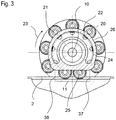
- the section 11 extends from a first position 37 at the tube 2 towards a second position 38 at the tube 2, which corresponds to a start of the linear section 25 resp. an end of the linear section 25.
- FIGS 4A to 4G show a sectional side view of the pump head 9 during operation of the pump 1.
- the movement of a squeeze member 20 along the guide member 24 during a rotation of the pump head 9 is shown.
- only one of the squeeze members 20 is depicted.
- the squeeze member 20 is located at the curved section 26 of the guide member 24.
- the shaft 21 of the squeeze member 20 may abut the curved section 26 or may be located in a distance from the curved section 26.
- the shaft 21 may be shiftable in the slot 21 from the curved section 26 in a radial direction away from the rotation axis 10.
- the exact radial position of the shaft 21 may be undefined.
- the squeeze member 20 enters the linear section 25 of the perimeter of the guide member 24 and arrives at the first position 37 at the section 11 of the tube 2 (see Figure 3 ).
- the squeeze member 20 is guided by the linear section 25 of the guide member 24 and by the tube guide 15.
- the shaft 21 abuts the linear section 25, whereby the radial movement of the squeeze member 20 towards the rotational axis 10 is delimited.
- the radial movement of the squeeze member 20 is delimited by the tube guide 25, on which the tube 2 is located.
- the radial position of the squeeze member 20 is determined by the linear section 25 of the guide member 24 and the tube 2. Because the linear section 25 and the tube guide 2 extend along the longitudinal axis 3, the radial position of the squeeze member 20 is adjusted such that a linear movement of the squeeze member 20 along the longitudinal axis 3 is caused.
- Figure 4D shows a position of the squeeze member 20 after a further rotation of the pump head 9.
- the squeeze member 20 has moved along the linear section 11 of the tube 2. Due to the linear movement of the squeeze member 20, a squeezed patch of the tube 2 is moved in the transport direction 4. Thereby, the material in the tube 2 is transported in the transport direction 4. Preferably, all along the linear section 25, the squeeze member 20 squeezes the tube 2 such that the tube 2 is closed. Thereby, a reflow of the material in a direction opposite to the transport direction 4 may be inhibited.
- Figure 4E shows a position of the squeeze member 20 after a further rotation of the pump head 9.
- the squeeze member 20 has reached the end of the linear section 25.
- the squeeze member 20 leaves the linear section 25 and enters the curved section 26 as shown in Figure 4F .
- the shaft 22 gets out of contact with the linear section 25 and is guided along the curved section 26.
- the squeeze member 20 is still in contact with the tube 2 but does not close the tube 2.
- Figure 4G shows the squeeze member 20 after a further rotation of the pump head 9. In this position, the squeeze member 20 is out of contact from the tube 2. On a further rotation, the squeeze member 20 is transported along the curved section 26 and reaches again the position as shown in Figure 4A .
- the squeeze members 20 are pressed by a resilient force towards the outside end of the slots 22 near the outer perimeter of the discs 18 and 19, for example by a spring force.
- shafts 21 of squeeze members 20 may be suspended by springs that press the shafts against the outside end of the slots 22.
- the guide member 24 is not required, as the squeeze members 20 squeeze the tube 2 by the spring forces.
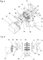
- Figure 5 shows a perspective exploded view of parts of the peristaltic pump 1 and Figure 6 shows an exploded view from the front of parts of the pump 1.
- the guide member 24 comprises a first part 29 and a second part 30, wherein the first part 29 guides the shafts 21 at one of their ends and the second part 30 guides the shafts 21 at their opposite ends.
- Each of the parts 29, 30 comprises a curved section 26 and a linear section 25.
- the first part 29 and the second part 30 are located on flanged members 31, 32, which are secured to a housing of the pump 1.
- the pump 1 comprises an engine 27, which drives the pump head 9 via gears 16.
- Bearings 33, 34 are arranged at the discs 18, 19 of the support member 17 to facilitate a rotational movement of the support member 17.
- a spacer ring 35 is arranged between the discs 18, 19 defining the distance between the discs 18, 19.
- FIG 7 shows the peristaltic pump 1 of Figure 1 , wherein the exchange part 13 has been removed from the main part 12.
- the exchange part 13 may be configured to be disposed after one or several operations of the pump 1 and replaced by a new exchange part 13. Alternatively, only parts of the exchange part 13 may be configured to be disposed, for example the needles 6, 8 or the tube 2.
- the pump 1 may be configured such that for detaching and attaching the exchange part 13 from the main part 12, the exchange part 13 may have to be moved in directions 28 perpendicular to the longitudinal axis 3. In this case, it may be necessary to remove the cartridge or container 5 from the receptacle of the main part 12 before the exchange part 13 can be detached or attached to the main part 12, because otherwise an attachment may be blocked by an interaction of the needle 6 with the cartridge or container 5.
- the pump 1 may be configured such that the exchange part 13 can be detached and attached by moving the exchange part 13 in a direction parallel to the longitudinal axis 3. In this case, it may not be necessary to remove the cartridge or container 5 from the main part 12 in order to detach or attach the exchange part 13.
- the first needle 6 may be inserted into the cartridge or container 5 during an attachment movement.
Landscapes
- Engineering & Computer Science (AREA)
- Health & Medical Sciences (AREA)
- Mechanical Engineering (AREA)
- General Engineering & Computer Science (AREA)
- Hematology (AREA)
- Anesthesiology (AREA)
- Biomedical Technology (AREA)
- Heart & Thoracic Surgery (AREA)
- Vascular Medicine (AREA)
- Life Sciences & Earth Sciences (AREA)
- Animal Behavior & Ethology (AREA)
- General Health & Medical Sciences (AREA)
- Public Health (AREA)
- Veterinary Medicine (AREA)
- Infusion, Injection, And Reservoir Apparatuses (AREA)
- Reciprocating Pumps (AREA)
Description
- The present disclosure relates to a peristaltic pump. Peristaltic pumps are configured to transport a material in a tube by squeezing the tube.
- Peristaltic pumps are known, for example, from the documents
DE 10246469 A1 andDE 19729612 A1 . - A further peristaltic pump according to the preamble of
claim 1 is known from documentGB 979 330 - It is an object of the present invention to provide a peristaltic pump with improved properties.
- The present invention provides a peristaltic pump, comprising a tube for transporting a material, wherein the tube is arranged along a longitudinal axis, a pump head configured to cause a squeezing of the tube, wherein the pump head is rotatable about a rotation axis, wherein the pump head comprises at least one squeeze member for squeezing the tube, and a support member, characterised in that the support member comprises a slot for supporting the at least one squeeze member, the slot extending in a radial direction relative to the rotation axis, such that a movement of the at least one squeeze member in a radial direction is enabled.
- The peristaltic pump may be configured to be applied for medical use. Preferably, the peristaltic pump is configured to transport a medicament, for example a fluid medicament. In particular, the pump may be used in the field of micro fluidics. As an example, the peristaltic pump may be configured to dispense small amounts of fluids. The pump may be used for a transporting a highly sensitive material. The material to be transported may be a medicament, for example insulin. Accordingly, the peristaltic pump may be used as a drug delivery device.
- The peristaltic pump may comprise a receptacle. The receptacle may be configured to receive a cartridge or container holding the material to be transported.
- Due to the arrangement of the tube along a longitudinal axis, an exchange of the tube may become easy and reproducible, since the handling and positioning of the tube may be facilitated. Thereby, the risk of misalignment of the tube, for example relative to the pump head, may be reduced. This may lead to a higher dosing accuracy after an exchange of the tube.
- Preferably, the tube is arranged along the longitudinal axis at least in a section of the tube which is configured to be squeezed for transporting the material. Preferably, the tube is arranged along the longitudinal axis along its entire length. Preferably, the tube is free of curved sections. In particular, the tube may be free of U-shaped sections.
- Preferably, the pump is configured such that the material is transported in a transport direction. Preferably, the transport direction is parallel to the longitudinal axis.
- Preferably, the pump head causes a squeezing of the tube along the longitudinal axis of the tube, in particular along the transport direction. Thereby, a transport of the material in the transport direction may be caused. In particular, the pump head may be configured such that a squeezed patch of the tube moves along the longitudinal axis. This may lead to an overpressure in the tube in front of the squeezed patch, which may lead to a movement of the material in the transport direction.
- Preferably, the rotation axis of the pump head is perpendicular to the longitudinal axis.
- In this case, a compact size of the peristaltic pump may be achieved, because the pump head may have a small dimension in direction of the longitudinal axis.
- The pump head comprises at least one squeeze member for squeezing the tube.
- In particular, the squeeze member may be configured to be in mechanical contact with the tube for squeezing the tube. Preferably, the squeeze member may be configured to close the tube at least at a particular time when squeezing the tube. In a preferred embodiment, the squeeze member squeezes the tube in a section of the tube running along the longitudinal axis. The section may run from a first position at the tube to a second position at the tube. Preferably, the squeeze member squeezes the tube continuously from the first position to the second position and thereby moves the squeezed patch from the first position to the second position.
- In a preferred embodiment, the peristaltic pump is configured such that the squeeze member is enabled to roll off on the tube when squeezing the tube.
- In this way, friction forces may be kept small. Thereby, an axial deformation of the tube or a displacement of the tube in axial direction may be prevented. Furthermore, a low driving force for driving the pump head may be sufficient such that the driving motor can be kept small. In particular, the friction force between the squeeze member and the tube may be a rolling friction force, which is smaller than a sliding friction force. As an example, the squeeze member may comprise a spherical or cylindrical member, for example a ball or a roller.
- Preferably, the pump head is configured to be operated at a constant driving speed. Thereby, a constant, nearly shock free pumping may be achieved with a low variation of a pumping pressure. Furthermore, a high dosing accuracy may be achieved.
- The pump head comprises a support member for supporting the squeeze member.
- Preferably, by a rotation of the pump head also the support member rotates, in particular rotates about the rotation axis of the pump head.
- In a preferred embodiment, the squeeze member is supported by the support member such that a rotation of the squeeze member relative to the support member is enabled.
- In particular, the squeeze member may be rotatable relative to the support member about a further rotation axis, arranged in a distance from the rotation axis of the pump head. The further rotation axis may run through the center of the squeeze member. The further rotation axis may be parallel to the rotation axis of the pump head. Preferably, the squeeze member is rotatable both about the rotation axis of the pump head and about the further rotation axis.
- The support member may comprise a disk-like shape. The squeeze member may be located near an outer perimeter of the support member. The squeeze member may be supported on the support member by a shaft. The shaft may run through the squeeze member. The shaft may be in direct contact with the support member. In one embodiment, the support member comprises two parts. Each of the parts may support an end of the shaft. The squeeze member may be located between the two parts of the support member.
- The the pump is configured such that the squeeze member is shiftable in a radial direction relative to the rotation axis.
- Thereby, an adjustment of the radial position of the squeeze member relative to the rotation axis may be enabled. In particular, the distance of the squeeze member to the rotation axis of the pump head may be adjustable.
- The squeeze member is supported by the support member such that a movement in a radial direction is enabled. The support member comprises a slot for supporting the squeeze member. The squeeze member may be shiftable in the slot.
- In particular, the squeeze member may be supported by a shaft being guided in the slot. The slot extends in radial direction such that a movement of the squeeze member in radial direction is enabled.
- In a preferred embodiment, the pump is configured such that a movement of the squeeze member along the longitudinal axis of the tube is enabled. Preferably, a movement along the longitudinal axis may be enabled at least along a section of the tube. In particular, the squeeze member may carry out a linear movement along the tube.
- Thereby, the squeeze member may squeeze the tube and move the squeezed patch of the tube along the longitudinal axis. Preferably, the squeeze member squeezes the tube at the squeezed patch such that the tube is closed in the squeezed patch in a section running along the longitudinal axis. Thereby, a reflow of material can be prevented.
- In a preferred embodiment, the peristaltic pump comprises a guide member for guiding a movement of the squeeze member.
- In particular, the guide member may confine a movement of the squeeze member in a radial direction relative to the rotation axis of the pump head. In particular, the guide member may confine a movement in the radial direction towards the rotation axis.
- Preferably, the guide member is secured to a housing of the pump such that relative movements between the guide member and the housing are prevented. In particular, the guide member may be non-rotatable.
- The squeeze member may be supported by a shaft, wherein a movement of the shaft in radial direction may be confined by a mechanical stop of the guide member. In particular, when the shaft abuts the guide member, a movement of the shaft in a radial direction, in particular towards the rotation axis of the pump head, may be prevented.
- The guide member may be configured to guide a movement of the squeeze member along the longitudinal axis.
- In particular, the guide member may guide the squeeze member in an axial movement of the squeeze member, preferably in a section of the tube which is configured to be squeezed by the squeeze member. In particular, during the axial movement of the squeeze member the squeeze member may squeeze the tube and thereby displace a squeezed patch of the tube in axial direction.
- The peristaltic pump may further comprise a tube guide for guiding the tube.
- In particular, the tube may be located on the tube guide. The tube guide may serve to position the tube in the pump. The tube may be attached to the tube guide. As an example, the tube guide may comprise a longitudinal grove in which the tube runs. The tube may be positioned between the tube guide and the pump head.
- The guide member may cooperate with the tube guide to cause a movement of the squeeze member along the longitudinal axis. In particular, the guide member may be arranged such relative to the tube guide that the radial position of the squeeze member is confined in one radial direction by the guide member and in the opposite radial direction by the tube guide. Preferably, along a section of the tube, the radial position of the squeeze member is determined by the guide member and the tube guide.
- Preferably, the axial movement of the squeeze member is enabled by a shiftability of the squeeze member as described above. Thereby, during rotation of the pump head the radial position of the squeeze member may be adjusted such that an axial movement of the squeeze member results.
- In a preferred embodiment, a perimeter of the guide member comprises a linear section extending parallel to the longitudinal axis of the tube.
- In particular, the squeeze member may be guided along the linear section when moving in an axial direction and squeezing the tube. As an example, a shaft for supporting the squeeze member may run along the perimeter of the guide member. When the shaft runs along the linear section, in particular abuts the linear section, the squeeze member may be guided in an axial movement.
- Furthermore, the perimeter of the guide member may comprise a curved section.
- The squeeze member may run along the curved section when not squeezing the tube. In particular, the squeeze member may be transported back from a second position at the tube to a first position at the tube when running along the curved section. Preferably, the curved section delimits a radial movement of the squeeze member towards the rotation axis. However, a radial movement of the squeeze member in the opposite radial direction may be allowed.
- The peristaltic pump may comprise a plurality of squeeze members.
- Preferably, the squeeze members are arranged on a support member of the pump head. In particular, the squeeze members may be arranged near an outer perimeter of the support member. In particular, the squeeze members may be arranged at regular distances from each other.
- Preferably, at any time during an operation of the pump, at least one of the squeeze members squeezes the pump, in particular such that the pump is closed. Thereby, a reflow of the material in a direction opposite to the transport direction may be prevented. Accordingly, the squeeze members may serve as valves.
- In a preferred embodiment, the peristaltic pump comprises a main part and an exchange part. The exchange part may be configured to the detachable from the main part.
- The exchange part may be configured to carry elements of the peristaltic pump which have to be exchanged periodically. As an example, the exchange part may carry the tube or a needle. Preferably, the elements which are carried by the exchange part are pre-assembled at the exchange part. This may allow an easy and quick exchange of parts of the pump. The exchange part may be configured to be disposable such that the exchange part may be replaced by a new exchange part. In a further embodiment, the exchange part may be configured such that a separate exchange of individual elements, such as a needle or the tube, may be enabled.
- Preferably, the exchange part comprises a tube guide for guiding the tube. The exchange part may comprise the tube.
- The main body may comprise the pump head. Furthermore, the main body may comprise a receptacle for receiving a cartridge or container holding the material to be transported.
- The peristaltic pump may comprise at least one needle. As an example, the exchange part may be configured to carry at least one needle.
- In particular, a needle may be provided for dispensing the material from a dispensing end of the pump. The needle may be in fluid connection with the tube. Additionally or alternatively, the pump may comprise at least one needle by which the tube is provided with new material. In particular, the needle may be configured to be inserted into a cartridge or container such that the material can flow from the cartridge or container into the tube.
- The term "medicament", as used herein, preferably means a pharmaceutical formulation containing at least one pharmaceutically active compound,
wherein in one embodiment the pharmaceutically active compound has a molecular weight up to 1500 Da and/or is a peptide, a proteine, a polysaccharide, a vaccine, a DNA, a RNA, an enzyme, an antibody or a fragment thereof, a hormone or an oligonucleotide, or a mixture of the above-mentioned pharmaceutically active compound,
wherein in a further embodiment the pharmaceutically active compound is useful for the treatment and/or prophylaxis of diabetes mellitus or complications associated with diabetes mellitus such as diabetic retinopathy, thromboembolism disorders such as deep vein or pulmonary thromboembolism, acute coronary syndrome (ACS), angina, myocardial infarction, cancer, macular degeneration, inflammation, hay fever, atherosclerosis and/or rheumatoid arthritis,
wherein in a further embodiment the pharmaceutically active compound comprises at least one peptide for the treatment and/or prophylaxis of diabetes mellitus or complications associated with diabetes mellitus such as diabetic retinopathy,
wherein in a further embodiment the pharmaceutically active compound comprises at least one human insulin or a human insulin analogue or derivative, glucagon-like peptide (GLP-1) or an analogue or derivative thereof, or exendin-3 or exendin-4 or an analogue or derivative of exendin-3 or exendin-4. - Insulin analogues are for example Gly(A21), Arg(B31), Arg(B32) human insulin; Lys(B3), Glu(B29) human insulin; Lys(B28), Pro(B29) human insulin; Asp(B28) human insulin; human insulin, wherein proline in position B28 is replaced by Asp, Lys, Leu, Val or Ala and wherein in position B29 Lys may be replaced by Pro; Ala(B26) human insulin; Des(B28-B30) human insulin; Des(B27) human insulin and Des(B30) human insulin.
- Insulin derivates are for example B29-N-myristoyl-des(B30) human insulin; B29-N-palmitoyl-des(B30) human insulin; B29-N-myristoyl human insulin; B29-N-palmitoyl human insulin; B28-N-myristoyl LysB28ProB29 human insulin; B28-N-palmitoyl-LysB28ProB29 human insulin; B30-N-myristoyl-ThrB29LysB30 human insulin; B30-N-palmitoyl- ThrB29LysB30 human insulin; B29-N-(N-palmitoyl-Y-glutamyl)-des(B30) human insulin; B29-N-(N-lithocholyl-Y-glutamyl)-des(B30) human insulin; B29-N-(ω-carboxyheptadecanoyl)-des(B30) human insulin and B29-N-(ω-carboxyheptadecanoyl) human insulin.
- Exendin-4 for example means Exendin-4(1-39), a peptide of the sequence H-His-Gly-Glu-Gly-Thr-Phe-Thr-Ser-Asp-Leu-Ser-Lys-Gln-Met-Glu-Glu-Glu-Ala-Val-Arg-Leu-Phe-Ile-Glu-Trp-Leu-Lys-Asn-Gly-Gly-Pro-Ser-Ser-Gly-Ala-Pro-Pro-Pro-Ser-NH2.
- Exendin-4 derivatives are for example selected from the following list of compounds:
- H-(Lys)4-des Pro36, des Pro37 Exendin-4(1-39)-NH2,
- H-(Lys)5-des Pro36, des Pro37 Exendin-4(1-39)-NH2,
- des Pro36 Exendin-4(1-39),
- des Pro36 [Asp28] Exendin-4(1-39),
- des Pro36 [IsoAsp28] Exendin-4(1-39),
- des Pro36 [Met(O)14, Asp28] Exendin-4(1-39),
- des Pro36 [Met(O)14, IsoAsp28] Exendin-4(1-39),
- des Pro36 [Trp(O2)25, Asp28] Exendin-4(1-39),
- des Pro36 [Trp(O2)25, IsoAsp28] Exendin-4(1-39),
- des Pro36 [Met(O)14 Trp(O2)25, Asp28] Exendin-4(1-39),
- des Pro36 [Met(O)14 Trp(O2)25, IsoAsp28] Exendin-4(1-39); or
- des Pro36 [Asp28] Exendin-4(1-39),
- des Pro36 [IsoAsp28] Exendin-4(1-39),
- des Pro36 [Met(O)14, Asp28] Exendin-4(1-39),
- des Pro36 [Met(O)14, IsoAsp28] Exendin-4(1-39),
- des Pro36 [Trp(O2)25, Asp28] Exendin-4(1-39),
- des Pro36 [Trp(O2)25, IsoAsp28] Exendin-4(1-39),
- des Pro36 [Met(O)14 Trp(O2)25, Asp28] Exendin-4(1-39),
- des Pro36 [Met(O)14 Trp(O2)25, IsoAsp28] Exendin-4(1-39),
- wherein the group -Lys6-NH2 may be bound to the C-terminus of the Exendin-4 derivative;
- or an Exendin-4 derivative of the sequence
- des Pro36 Exendin-4(1-39)-Lys6-NH2 (AVE0010),
- H-(Lys)6-des Pro36 [Asp28] Exendin-4(1-39)-Lys6-NH2,
- des Asp28 Pro36, Pro37, Pro38Exendin-4(1-39)-NH2,
- H-(Lys)6-des Pro36, Pro38 [Asp28] Exendin-4(1-39)-NH2,
- H-Asn-(Glu)5des Pro36, Pro37, Pro38 [Asp28] Exendin-4(1-39)-NH2,
- des Pro36, Pro37, Pro38 [Asp28] Exendin-4(1-39)-(Lys)6-NH2,
- H-(Lys)6-des Pro36, Pro37, Pro38 [Asp28] Exendin-4(1-39)-(Lys)6-NH2,
- H-Asn-(Glu)5-des Pro36, Pro37, Pro38 [Asp28] Exendin-4(1-39)-(Lys)6-NH2,
- H-(Lys)6-des Pro36 [Trp(O2)25, Asp28] Exendin-4(1-39)-Lys6-NH2,
- H-des Asp28 Pro36, Pro37, Pro38 [Trp(O2)25] Exendin-4(1-39)-NH2,
- H-(Lys)6-des Pro36, Pro37, Pro38 [Trp(O2)25, Asp28] Exendin-4(1-39)-NH2,
- H-Asn-(Glu)5-des Pro36, Pro37, Pro38 [Trp(O2)25, Asp28] Exendin-4(1-39)-NH2,
- des Pro36, Pro37, Pro38 [Trp(O2)25, Asp28] Exendin-4(1-39)-(Lys)6-NH2,
- H-(Lys)6-des Pro36, Pro37, Pro38 [Trp(O2)25, Asp28] Exendin-4(1-39)-(Lys)6-NH2,
- H-Asn-(Glu)5-des Pro36, Pro37, Pro38 [Trp(O2)25, Asp28] Exendin-4(1-39)-(Lys)6-NH2,
- H-(Lys)6-des Pro36 [Met(O)14, Asp28] Exendin-4(1-39)-Lys6-NH2,
- des Met(O)14 Asp28 Pro36, Pro37, Pro38 Exendin-4(1-39)-NH2,
- H-(Lys)6-desPro36, Pro37, Pro38 [Met(O)14, Asp28] Exendin-4(1-39)-NH2,
- H-Asn-(Glu)5-des Pro36, Pro37, Pro38 [Met(O)14, Asp28] Exendin-4(1-39)-NH2,
- des Pro36, Pro37, Pro38 [Met(O)14, Asp28] Exendin-4(1-39)-(Lys)6-NH2,
- H-(Lys)6-des Pro36, Pro37, Pro38 [Met(O)14, Asp28] Exendin-4(1-39)-(Lys)6-NH2,
- H-Asn-(Glu)5 des Pro36, Pro37, Pro38 [Met(O)14, Asp28] Exendin-4(1-39)-(Lys)6-NH2,
- H-Lys6-des Pro36 [Met(O)14, Trp(O2)25, Asp28] Exendin-4(1-39)-Lys6-NH2,
- H-des Asp28 Pro36, Pro37, Pro38 [Met(O)14, Trp(O2)25] Exendin-4(1-39)-NH2,
- H-(Lys)6-des Pro36, Pro37, Pro38 [Met(O)14, Asp28] Exendin-4(1-39)-NH2,
- H-Asn-(Glu)5-des Pro36, Pro37, Pro38 [Met(O)14, Trp(O2)25, Asp28] Exendin-4(1-39)-NH2,
- des Pro36, Pro37, Pro38 [Met(O)14, Trp(O2)25, Asp28] Exendin-4(1-39)-(Lys)6-NH2,
- H-(Lys)6-des Pro36, Pro37, Pro38 [Met(O)14, Trp(O2)25, Asp28] Exendin-4(S1-39)-(Lys)6-NH2,
- H-Asn-(Glu)5-des Pro36, Pro37, Pro38 [Met(O)14, Trp(O2)25, Asp28] Exendin-4(1-39)-(Lys)6-NH2;
- Hormones are for example hypophysis hormones or hypothalamus hormones or regulatory active peptides and their antagonists as listed in Rote Liste, ed. 2008, Chapter 50, such as Gonadotropine (Follitropin, Lutropin, Choriongonadotropin, Menotropin), Somatropine (Somatropin), Desmopressin, Terlipressin, Gonadorelin, Triptorelin, Leuprorelin, Buserelin, Nafarelin, Goserelin.
- A polysaccharide is for example a glucosaminoglycane, a hyaluronic acid, a heparin, a low molecular weight heparin or an ultra low molecular weight heparin or a derivative thereof, or a sulphated, e.g. a poly-sulphated form of the above-mentioned polysaccharides, and/or a pharmaceutically acceptable salt thereof. An example of a pharmaceutically acceptable salt of a poly-sulphated low molecular weight heparin is enoxaparin sodium.
- Antibodies are globular plasma proteins (-150 kDa) that are also known as immunoglobulins which share a basic structure. As they have sugar chains added to amino acid residues, they are glycoproteins. The basic functional unit of each antibody is an immunoglobulin (Ig) monomer (containing only one Ig unit); secreted antibodies can also be dimeric with two Ig units as with IgA, tetrameric with four Ig units like teleost fish IgM, or pentameric with five Ig units, like mammalian IgM.
- The Ig monomer is a "Y"-shaped molecule that consists of four polypeptide chains; two identical heavy chains and two identical light chains connected by disulfide bonds between cysteine residues. Each heavy chain is about 440 amino acids long; each light chain is about 220 amino acids long. Heavy and light chains each contain intrachain disulfide bonds which stabilize their folding. Each chain is composed of structural domains called Ig domains. These domains contain about 70-110 amino acids and are classified into different categories (for example, variable or V, and constant or C) according to their size and function. They have a characteristic immunoglobulin fold in which two β sheets create a "sandwich" shape, held together by interactions between conserved cysteines and other charged amino acids.
- There are five types of mammalian Ig heavy chain denoted by α, δ, ε, γ, and µ. The type of heavy chain present defines the isotype of antibody; these chains are found in IgA, IgD, IgE, IgG, and IgM antibodies, respectively.
- Distinct heavy chains differ in size and composition; α and γ contain approximately 450 amino acids and δ approximately 500 amino acids, while µ and ε have approximately 550 amino acids. Each heavy chain has two regions, the constant region (CH) and the variable region (VH). In one species, the constant region is essentially identical in all antibodies of the same isotype, but differs in antibodies of different isotypes. Heavy chains γ, α and δ have a constant region composed of three tandem Ig domains, and a hinge region for added flexibility; heavy chains µ and ε have a constant region composed of four immunoglobulin domains. The variable region of the heavy chain differs in antibodies produced by different B cells, but is the same for all antibodies produced by a single B cell or B cell clone. The variable region of each heavy chain is approximately 110 amino acids long and is composed of a single Ig domain.
- In mammals, there are two types of immunoglobulin light chain denoted by λ and κ. A light chain has two successive domains: one constant domain (CL) and one variable domain (VL). The approximate length of a light chain is 211 to 217 amino acids. Each antibody contains two light chains that are always identical; only one type of light chain, κ or λ, is present per antibody in mammals.
- Although the general structure of all antibodies is very similar, the unique property of a given antibody is determined by the variable (V) regions, as detailed above. More specifically, variable loops, three each the light (VL) and three on the heavy (VH) chain, are responsible for binding to the antigen, i.e. for its antigen specificity. These loops are referred to as the Complementarity Determining Regions (CDRs). Because CDRs from both VH and VL domains contribute to the antigen-binding site, it is the combination of the heavy and the light chains, and not either alone, that determines the final antigen specificity.
- An "antibody fragment" contains at least one antigen binding fragment as defined above, and exhibits essentially the same function and specificity as the complete antibody of which the fragment is derived from. Limited proteolytic digestion with papain cleaves the Ig prototype into three fragments. Two identical amino terminal fragments, each containing one entire L chain and about half an H chain, are the antigen binding fragments (Fab). The third fragment, similar in size but containing the carboxyl terminal half of both heavy chains with their interchain disulfide bond, is the crystalizable fragment (Fc). The Fc contains carbohydrates, complement-binding, and FcR-binding sites. Limited pepsin digestion yields a single F(ab')2 fragment containing both Fab pieces and the hinge region, including the H-H interchain disulfide bond. F(ab')2 is divalent for antigen binding. The disulfide bond of F(ab')2 may be cleaved in order to obtain Fab'. Moreover, the variable regions of the heavy and light chains can be fused together to form a single chain variable fragment (scFv).
- Pharmaceutically acceptable salts are for example acid addition salts and basic salts. Acid addition salts are e.g. HCI or HBr salts. Basic salts are e.g. salts having a cation selected from alkali or alkaline, e.g. Na+, or K+, or Ca2+, or an ammonium ion N+(R1)(R2)(R3)(R4), wherein R1 to R4 independently of each other mean: hydrogen, an optionally substituted C1-C6-alkyl group, an optionally substituted C2-C6-alkenyl group, an optionally substituted C6-C10-aryl group, or an optionally substituted C6-C10-heteroaryl group. Further examples of pharmaceutically acceptable salts are described in "Remington's Pharmaceutical Sciences" 17. ed. Alfonso R. Gennaro (Ed.), Mark Publishing Company, Easton, Pa., U.S.A., 1985 and in Encyclopedia of Pharmaceutical Technology.
- Pharmaceutically acceptable solvates are for example hydrates.
- Further features, refinements and expediencies become apparent from the following description of the exemplary embodiments in connection with the figures.
-
Figure 1 shows a sectional side view of a peristaltic pump. -
Figure 2 shows a perspective view of the pump head of the peristaltic pump ofFigure 1 . -
Figure 3 shows a side view of the pump head of the pump ofFigure 1 . -
Figures 4A to 4G show a sectional side view of the pump head during the operation of the pump ofFigure 1 . -
Figure 5 shows a perspective exploded view of parts of the peristaltic pump ofFigure 1 . -
Figure 6 shows an exploded view from the front of parts of the peristaltic pump ofFigure 1 . -
Figure 7 shows a sectional side view of the peristaltic pump ofFigure 1 with an exchange part being detached from a main body. - Like elements, elements of the same kind and identically acting elements may be provided with the same reference numerals in the figures.
-
Figure 1 shows a sectional side view of an embodiment of aperistaltic pump 1. Thepump 1 comprises alinear tube 2 extending along alongitudinal axis 3. Thetube 2 is free from curved portions. A material is transported through thetube 2 in atransport direction 4. Thetransport direction 4 is parallel to thelongitudinal axis 3. - The material to be transported is held by a cartridge or
container 5 positioned in a receptacle, for example a glass cartridge. As an example, theperistaltic pump 1 may be configured to transport and dispense a medical fluid, for example insulin. Theperistaltic pump 1 may be particularly suitable for transporting small amounts of a fluid, such that theperistaltic pump 1 may be used in the field of micro fluidics. Thecartridge 5 may comprise a piston. The piston may be axially movable in thecartridge 5. Aspring 36 may exert a force on the piston to facilitate a movement of the piston. Thereby, air pockets in thereceptacle 5 may be prevented when material is drawn from thecartridge 5 into thetube 2. Thecartridge 5 may also be made from a different material, for example synthetic material like plastics. The cartridge orcontainer 5 may also be made from a collapsible or flexible material. In this case, a piston is not required. - The
peristaltic pump 1 comprises afirst needle 6, which is in fluid communication with the cartridge orcontainer 5 and connects the cartridge orcontainer 5 to thetube 2. Thefirst needle 6 may pierce a septum of the cartridge orcontainer 5. At adispending end 7 of theperistaltic pump 1, asecond needle 8 is located. Thesecond needle 8 is in fluid communication with thetube 2. Preferably, thesecond needle 8 is insertable in a tissue to dispense the material. - The
peristaltic pump 1 comprises amain part 12 and anexchange part 13. Theexchange part 13 is detachably attached to themain part 12. Thereby, a replacement of theexchange part 13 or of individual components of theexchange part 13 may be enabled. Preferably, theexchange part 13 comprises parts of theperistaltic pump 1 which have to be exchanged periodically, such as theneedles tube 2. - The
main part 12 comprises ahousing 14 which houses apump head 9 and the receptacle for the cartridge andcontainer 5. Theexchange part 13 comprises atube guide 15, wherein thetube 2 is guided. Thetube 2 may be detachably attached to thetube guide 15 such that thetube 2 in theexchange part 13 may be individually replaceable. As a further example, thetube 2 may be permanently attached to the exchange part, for example glued to thetube guide 15. - The
pump head 9 of thepump 1 is rotatably mounted. Thepump head 9 is rotatable about arotation axis 10 in arotational direction 23. By a rotation of thepump head 9, a squeezing of thetube 2 along thelongitudinal axis 3 is caused such that a squeezed patch of thetube 2 propagates intransport direction 4. In particular, the squeezing of thetube 2 is caused in asection 11 of the tube. - The
pump head 9 comprises asupport member 17 supporting a plurality ofsqueeze members 20. In this embodiment, the squeeze members are configured as rollers. Thesqueeze members 20 are rotatably mounted on thesupport member 17 such that a relative rotational movement of thesqueeze members 20 and thesupport member 17 is enabled. In particular, eachsqueeze member 20 is mounted on thesupport member 17 by ashaft 21 such that thesqueeze member 20 is rotatable about a further rotational axis running through the center of theshaft 21. Therotational axis 10 and the further rotational axis are parallel to each other and are perpendicular to thelongitudinal axis 3. - When the
pump head 9 and thereby also thesupport member 17 and thesqueeze members 20 are rotated about therotational axis 10, asqueeze member 20 comes into contact with thetube 20, squeezes the tube along at least thesection 11 and then leaves thetube 2. The rotatable mounting of thesqueeze member 20 on thesupport member 17 enables thesqueeze member 20 to roll off on thetube 2 when squeezing thetube 2. Thereby, friction forces may be kept low and an axial deformation of thetube 2 may be reduced. - The
squeeze members 20 are shiftably mounted such that a displacement of thesqueeze members 20 in a radial direction relative to therotation axis 10 is enabled. In particular, theshafts 21 are located inradial slots 22 of thesupport member 17 such that a displacement of theshafts 21 and, thereby, of thesqueeze members 20 in a radial direction is enabled. - Due to this shiftability, the
squeeze members 20 are enabled to move linearly along thelongitudinal axis 3 when squeezing thetube 2 in thetube section 11. In particular, during a rotation of thepump head 9 about therotation axis 10, the radial position of thesqueeze members 20 relative to therotation axis 10 can be adjusted such that thesqueeze members 20 are urged into a linear movement along thelongitudinal axis 3 at least along thesection 11 of thetube 2. Thereby, a squeezing of thetube 2 along a linear path is enabled. - In the following, the working principle of the pump of
Figure 1 is described in more detail in connection withFigures 2 ,3 and4A to 4G . -
Figure 2 shows a perspective view of thepump head 9 in theperistaltic pump 1 ofFigure 1 . - The
support member 17 comprises twocircular discs squeeze members 20 are located between thecircular discs circular discs slots 22, wherein theshafts 21 are shiftably mounted. - In order to urge the
squeeze members 20 into a movement along thelongitudinal axis 3 in thesection 11 of thetube 2, theperistaltic pump 1 comprises aguide member 24. - The
shafts 21 of thesqueeze members 22 are arranged such that the ends of theshafts 21 run along the outer perimeter of theguide member 24 during a rotation of thepump head 9. Thereby, the radial movement of thesqueeze members 22 in a direction towards therotation axis 10 is confined by theguide member 24. In particular, when ashaft 21 abuts the outer perimeter of theguide member 24, a further movement in a radial direction towards therotation axis 10 is prevented. - As can be seen in
Figure 3 , the perimeter of theguide member 24 comprises alinear section 25, which may also be denoted as the guide rail, and acurved section 26. During operation of thepump 1, eachshaft 21 and, thereby, eachsqueeze member 20 is moved along the perimeter of theguide member 24 in therotational direction 23. When asqueeze member 20 is guided along thelinear section 25, it moves linearly along thelongitudinal axis 3. The length of thelinear section 25 corresponds to the length of thesection 11, in which the squeeze member moves linearly along thetube 2 and, thereby, squeezes thetube 2. Thesection 11 extends from afirst position 37 at thetube 2 towards asecond position 38 at thetube 2, which corresponds to a start of thelinear section 25 resp. an end of thelinear section 25. -
Figures 4A to 4G show a sectional side view of thepump head 9 during operation of thepump 1. In particular, the movement of asqueeze member 20 along theguide member 24 during a rotation of thepump head 9 is shown. For clarity reasons, only one of thesqueeze members 20 is depicted. - In
Figure 4A , thesqueeze member 20 is located at thecurved section 26 of theguide member 24. In particular, theshaft 21 of thesqueeze member 20 may abut thecurved section 26 or may be located in a distance from thecurved section 26. Theshaft 21 may be shiftable in theslot 21 from thecurved section 26 in a radial direction away from therotation axis 10. Thus, when theshaft 21 is guided along thecurved section 26, the exact radial position of theshaft 21 may be undefined. - As shown in
Figure 4B , when thepump head 9 and, thereby, thesupport member 17 and thesqueeze member 20 is rotated further in therotational direction 23, thesqueeze member 20 reaches the end of thecurved section 26 and gets into contact with thetube 2. - As shown in
Figure 4C , on a further rotation of thepump head 9, thesqueeze member 20 enters thelinear section 25 of the perimeter of theguide member 24 and arrives at thefirst position 37 at thesection 11 of the tube 2 (seeFigure 3 ). In thelinear section 25 of theguide member 24, thesqueeze member 20 is guided by thelinear section 25 of theguide member 24 and by thetube guide 15. In particular, theshaft 21 abuts thelinear section 25, whereby the radial movement of thesqueeze member 20 towards therotational axis 10 is delimited. In the opposite radial direction, the radial movement of thesqueeze member 20 is delimited by thetube guide 25, on which thetube 2 is located. Accordingly, the radial position of thesqueeze member 20 is determined by thelinear section 25 of theguide member 24 and thetube 2. Because thelinear section 25 and thetube guide 2 extend along thelongitudinal axis 3, the radial position of thesqueeze member 20 is adjusted such that a linear movement of thesqueeze member 20 along thelongitudinal axis 3 is caused. -
Figure 4D shows a position of thesqueeze member 20 after a further rotation of thepump head 9. Thesqueeze member 20 has moved along thelinear section 11 of thetube 2. Due to the linear movement of thesqueeze member 20, a squeezed patch of thetube 2 is moved in thetransport direction 4. Thereby, the material in thetube 2 is transported in thetransport direction 4. Preferably, all along thelinear section 25, thesqueeze member 20 squeezes thetube 2 such that thetube 2 is closed. Thereby, a reflow of the material in a direction opposite to thetransport direction 4 may be inhibited. - Due to the rotatable mounting of the
squeeze member 20 relative to thesupport member 17 thesqueeze member 20 rolls off on thetube 2 when squeezing thetube 2. -
Figure 4E shows a position of thesqueeze member 20 after a further rotation of thepump head 9. Thesqueeze member 20 has reached the end of thelinear section 25. - On a further rotation, the
squeeze member 20 leaves thelinear section 25 and enters thecurved section 26 as shown inFigure 4F . In particular, theshaft 22 gets out of contact with thelinear section 25 and is guided along thecurved section 26. In this position, thesqueeze member 20 is still in contact with thetube 2 but does not close thetube 2. -
Figure 4G shows thesqueeze member 20 after a further rotation of thepump head 9. In this position, thesqueeze member 20 is out of contact from thetube 2. On a further rotation, thesqueeze member 20 is transported along thecurved section 26 and reaches again the position as shown inFigure 4A . - Preferably, at any time during operation of the
pump 1, at least onesqueeze member 20 is in contact with thetube 2. More preferably, at least onesqueeze member 20 squeezes thetube 2 such that thetube 2 is closed. Thereby, a reflow of material may be inhibited. - In an alternative embodiment, the
squeeze members 20 are pressed by a resilient force towards the outside end of theslots 22 near the outer perimeter of thediscs shafts 21 ofsqueeze members 20 may be suspended by springs that press the shafts against the outside end of theslots 22. In such an embodiment, theguide member 24 is not required, as thesqueeze members 20 squeeze thetube 2 by the spring forces. - Further details of an embodiment of the
pump 1 ofFigure 1 can be seen fromFigures 5, 6 and7 . -
Figure 5 shows a perspective exploded view of parts of theperistaltic pump 1 andFigure 6 shows an exploded view from the front of parts of thepump 1. - As can be seen from
Figures 5 and 6 , theguide member 24 comprises afirst part 29 and asecond part 30, wherein thefirst part 29 guides theshafts 21 at one of their ends and thesecond part 30 guides theshafts 21 at their opposite ends. Each of theparts curved section 26 and alinear section 25. Thefirst part 29 and thesecond part 30 are located onflanged members pump 1. - Furthermore, the
pump 1 comprises anengine 27, which drives thepump head 9 via gears 16.Bearings discs support member 17 to facilitate a rotational movement of thesupport member 17. - Furthermore, a
spacer ring 35 is arranged between thediscs discs -
Figure 7 shows theperistaltic pump 1 ofFigure 1 , wherein theexchange part 13 has been removed from themain part 12. Theexchange part 13 may be configured to be disposed after one or several operations of thepump 1 and replaced by anew exchange part 13. Alternatively, only parts of theexchange part 13 may be configured to be disposed, for example theneedles tube 2. - The
pump 1 may be configured such that for detaching and attaching theexchange part 13 from themain part 12, theexchange part 13 may have to be moved indirections 28 perpendicular to thelongitudinal axis 3. In this case, it may be necessary to remove the cartridge orcontainer 5 from the receptacle of themain part 12 before theexchange part 13 can be detached or attached to themain part 12, because otherwise an attachment may be blocked by an interaction of theneedle 6 with the cartridge orcontainer 5. - In a further embodiment, the
pump 1 may be configured such that theexchange part 13 can be detached and attached by moving theexchange part 13 in a direction parallel to thelongitudinal axis 3. In this case, it may not be necessary to remove the cartridge orcontainer 5 from themain part 12 in order to detach or attach theexchange part 13. In particular, thefirst needle 6 may be inserted into the cartridge orcontainer 5 during an attachment movement. -
- 1
- peristaltic pump
- 2
- tube
- 3
- longitudinal axis
- 4
- transport direction
- 5
- cartridge / container
- 6
- first needle
- 7
- second needle
- 8
- dispensing end
- 9
- pump head
- 10
- rotation axis
- 11
- section of tube
- 12
- main part
- 13
- exchange part
- 14
- housing
- 15
- tube guide
- 16
- gear
- 17
- support member
- 18
- disc
- 19
- disc
- 20
- squeeze member
- 21
- shaft
- 22
- slot
- 23
- direction of rotation
- 24
- guide member
- 25
- linear section
- 26
- curved section
- 27
- engine
- 28
- direction of detachment and attachment of exchange part
- 29
- first part of guide member
- 30
- second part of guide member
- 31
- flanged member
- 32
- flanged member
- 33
- bearing
- 34
- bearing
- 35
- spacer ring
- 36
- spring
- 37
- first position
- 38
- second position
Claims (9)
- A peristaltic pump, comprising
a tube (2) for transporting a material, wherein the tube (2) is arranged along a longitudinal axis (3);
a pump head (9) configured to cause a squeezing of the tube (2), wherein the pump head (9) is rotatable about a rotation axis (10), wherein the pump head (9) comprises at least one squeeze member (20) for squeezing the tube (2); and
a support member (17);
characterised in that the support member (17) comprises a slot (22) for supporting the at least one squeeze member (20), the slot (22) extending in a radial direction relative to the rotation axis (10), such that a movement of the at least one squeeze member (20) in a radial direction is enabled. - The peristaltic pump of claim 1, wherein the tube (2) is arranged along the longitudinal axis (3) at least in a section of the tube (2) which is configured to be squeezed for transporting the material.
- The peristaltic pump of any of the previous claims, wherein the rotation axis (10) is perpendicular to the longitudinal axis (3).
- The peristaltic pump of any of the previous claims, being configured such that the at least one squeeze member (20) is enabled to roll off on the tube (2) when squeezing the tube (2).
- The peristaltic pump of any of the previous claims, wherein rotation of the at least one squeeze member (20) relative to the support member (17) is enabled.
- The peristaltic pump of any of the previous claims, comprising a guide member (24) for guiding a movement of the at least one squeeze member (20), optionally wherein:(i) the guide member (24) is configured to guide a movement of the at least one squeeze member (20) along the longitudinal axis (3); and/or(ii) a perimeter of the guide member (24) comprises a linear section (25) extending parallel to the longitudinal axis (3); and/or(iii) a perimeter of the guide member (24) comprises a curved section (26).
- The peristaltic pump of any of the previous claims, comprising a plurality of squeeze members (20).
- The peristaltic pump of any of the previous claims, comprising a main part (12) and an exchange part (13) configured to be detachable from the main part (12), optionally wherein:(i) the exchange part (13) comprises a tube guide (15) for guiding the tube (2); and/or(ii) the peristaltic pump comprises a receptacle for holding a container (5) for the material to be transported, wherein the receptacle is located in the main part (12).
- The peristaltic pump of any of the previous claims, being configured to transport a medicament.
Priority Applications (1)
| Application Number | Priority Date | Filing Date | Title |
|---|---|---|---|
| EP12759778.9A EP2764246B1 (en) | 2011-09-21 | 2012-09-21 | Peristaltic pump |
Applications Claiming Priority (3)
| Application Number | Priority Date | Filing Date | Title |
|---|---|---|---|
| EP11182228 | 2011-09-21 | ||
| EP12759778.9A EP2764246B1 (en) | 2011-09-21 | 2012-09-21 | Peristaltic pump |
| PCT/EP2012/068695 WO2013041702A1 (en) | 2011-09-21 | 2012-09-21 | Peristaltic pump |
Publications (2)
| Publication Number | Publication Date |
|---|---|
| EP2764246A1 EP2764246A1 (en) | 2014-08-13 |
| EP2764246B1 true EP2764246B1 (en) | 2019-05-01 |
Family
ID=46875870
Family Applications (1)
| Application Number | Title | Priority Date | Filing Date |
|---|---|---|---|
| EP12759778.9A Active EP2764246B1 (en) | 2011-09-21 | 2012-09-21 | Peristaltic pump |
Country Status (7)
| Country | Link |
|---|---|
| US (2) | US9586002B2 (en) |
| EP (1) | EP2764246B1 (en) |
| JP (2) | JP6194314B2 (en) |
| CA (1) | CA2845249A1 (en) |
| DK (1) | DK2764246T3 (en) |
| TR (1) | TR201910605T4 (en) |
| WO (1) | WO2013041702A1 (en) |
Families Citing this family (9)
| Publication number | Priority date | Publication date | Assignee | Title |
|---|---|---|---|---|
| EP2832390A1 (en) | 2013-07-30 | 2015-02-04 | Sensile Pat AG | Drug delivery device with needle actuation mechanism |
| US11260170B2 (en) | 2013-12-20 | 2022-03-01 | Sanofi-Aventis Deutschland Gmbh | Disposable delivery assembly for a drug delivery device |
| US10569012B2 (en) | 2013-12-20 | 2020-02-25 | Sanofi-Aventis Deutschland Gmbh | Drug delivery device with disposable cartridge and disposable injector |
| CN107213016B (en) * | 2016-03-21 | 2023-08-29 | 上海螭宿医药科技有限公司 | Disposable penicillin bottle dissolving and dispensing device for automatic dissolving and dispensing system |
| CN109331246B (en) * | 2018-09-28 | 2021-04-30 | 黄恒艺 | Medical drainage device |
| US11338288B2 (en) * | 2018-10-01 | 2022-05-24 | Boehringer Ingelheim Vetmedica Gmbh | Peristaltic pump and analyzer for testing a sample |
| DE102020113267A1 (en) | 2020-05-15 | 2021-11-18 | Aesculap Ag | Medical hose pump with stamp elements and associated hose arrangement |
| CZ202419A3 (en) | 2024-01-22 | 2025-07-30 | České vysoké učenà technické v Praze | A peristaltic pump for the transport of fluids or suspension |
| CN117948265A (en) * | 2024-03-27 | 2024-04-30 | 保定思诺流体科技有限公司 | Novel peristaltic pump |
Citations (1)
| Publication number | Priority date | Publication date | Assignee | Title |
|---|---|---|---|---|
| GB979330A (en) * | 1962-08-23 | 1965-01-01 | Technicon Instr | Compressible tube type fluid pump |
Family Cites Families (38)
| Publication number | Priority date | Publication date | Assignee | Title |
|---|---|---|---|---|
| US533575A (en) | 1895-02-05 | wilkens | ||
| JPH02145681U (en) * | 1989-05-16 | 1990-12-11 | ||
| US5226895A (en) | 1989-06-05 | 1993-07-13 | Eli Lilly And Company | Multiple dose injection pen |
| GB9007113D0 (en) | 1990-03-29 | 1990-05-30 | Sams Bernard | Dispensing device |
| ATE121953T1 (en) | 1991-07-24 | 1995-05-15 | Medico Dev Investment Co | INJECTOR. |
| DK175491D0 (en) | 1991-10-18 | 1991-10-18 | Novo Nordisk As | APPARATUS |
| US5279585A (en) | 1992-02-04 | 1994-01-18 | Becton, Dickinson And Company | Medication delivery pen having improved dose delivery features |
| US5320609A (en) | 1992-12-07 | 1994-06-14 | Habley Medical Technology Corporation | Automatic pharmaceutical dispensing syringe |
| US5383865A (en) | 1993-03-15 | 1995-01-24 | Eli Lilly And Company | Medication dispensing device |
| ZA941881B (en) | 1993-04-02 | 1995-09-18 | Lilly Co Eli | Manifold medication injection apparatus and method |
| US5582598A (en) | 1994-09-19 | 1996-12-10 | Becton Dickinson And Company | Medication delivery pen with variable increment dose scale |
| JP3568959B2 (en) | 1995-03-07 | 2004-09-22 | イーライ・リリー・アンド・カンパニー | Reusable dosing device |
| US5674204A (en) | 1995-09-19 | 1997-10-07 | Becton Dickinson And Company | Medication delivery pen cap actuated dose delivery clutch |
| US5688251A (en) | 1995-09-19 | 1997-11-18 | Becton Dickinson And Company | Cartridge loading and priming mechanism for a pen injector |
| JP2858304B2 (en) | 1996-02-16 | 1999-02-17 | 三和産業株式会社 | Pumping equipment |
| US6129699A (en) | 1997-10-31 | 2000-10-10 | Sorenson Development, Inc. | Portable persistaltic pump for peritoneal dialysis |
| DE19729612C2 (en) | 1997-07-10 | 2001-05-17 | Doering Gmbh | Peristaltic pump |
| DE19730999C1 (en) | 1997-07-18 | 1998-12-10 | Disetronic Licensing Ag | Injection pen dosing selected volume of fluid, especially insulin |
| US5921966A (en) | 1997-08-11 | 1999-07-13 | Becton Dickinson And Company | Medication delivery pen having an improved clutch assembly |
| CZ297361B6 (en) | 1998-01-30 | 2006-11-15 | Novo Nordisk A/S | Injection syringe |
| US6221053B1 (en) | 1998-02-20 | 2001-04-24 | Becton, Dickinson And Company | Multi-featured medication delivery pen |
| US6096010A (en) | 1998-02-20 | 2000-08-01 | Becton, Dickinson And Company | Repeat-dose medication delivery pen |
| US6248095B1 (en) | 1998-02-23 | 2001-06-19 | Becton, Dickinson And Company | Low-cost medication delivery pen |
| AU6892100A (en) | 1999-08-05 | 2001-03-05 | Becton Dickinson & Company | Medication delivery pen |
| GB0007071D0 (en) | 2000-03-24 | 2000-05-17 | Sams Bernard | One-way clutch mechanisms and injector devices |
| US6663602B2 (en) | 2000-06-16 | 2003-12-16 | Novo Nordisk A/S | Injection device |
| US6899699B2 (en) | 2001-01-05 | 2005-05-31 | Novo Nordisk A/S | Automatic injection device with reset feature |
| EP2275158B1 (en) | 2001-05-16 | 2013-01-23 | Eli Lilly and Company | Medication injector apparatus |
| DE10246469A1 (en) | 2002-10-04 | 2004-04-15 | Applica Gmbh | Pump with peristaltic drive for medical applications, has cam segments with defined ratio between lamella height and stroke |
| GB0304823D0 (en) | 2003-03-03 | 2003-04-09 | Dca Internat Ltd | Improvements in and relating to a pen-type injector |
| US7846126B2 (en) * | 2003-07-14 | 2010-12-07 | Abbott Medical Optics, Inc. | System and method for modulated surgical procedure irrigation and aspiration |
| FR2871858B1 (en) * | 2004-06-22 | 2006-10-27 | Gilson Sas Soc Par Actions Sim | PERISTALTIC PUMP COMPRISING A LOCKABLE REMOVABLE CASSETTE |
| FR2872553B1 (en) * | 2004-06-30 | 2006-09-22 | Millipore Corp | PERISTALTIC PUMP COMPRISING A SUPPORT MEMBER AND A BACK SUPPORT SUITABLE FOR COOPERATING WITH A TUBE |
| DE102004063647A1 (en) | 2004-12-31 | 2006-07-20 | Tecpharma Licensing Ag | Device for metered administration of a fluid product with coupling |
| WO2009107737A1 (en) * | 2008-02-28 | 2009-09-03 | 株式会社ジェイ・エム・エス | Injection device for semi-solidified nutritional supplement |
| US8647309B2 (en) | 2008-05-02 | 2014-02-11 | Sanofi-Aventis Deutschland Gmbh | Medication delivery device |
| SG2014010284A (en) * | 2011-08-17 | 2014-03-28 | Nestec Sa | Linear peristaltic pump |
| US20140021231A1 (en) * | 2012-06-29 | 2014-01-23 | Deborah Lynn Riat | bicycle U-lock carrier |
-
2012
- 2012-09-21 WO PCT/EP2012/068695 patent/WO2013041702A1/en not_active Ceased
- 2012-09-21 CA CA2845249A patent/CA2845249A1/en not_active Abandoned
- 2012-09-21 JP JP2014531252A patent/JP6194314B2/en not_active Expired - Fee Related
- 2012-09-21 US US14/240,797 patent/US9586002B2/en active Active
- 2012-09-21 EP EP12759778.9A patent/EP2764246B1/en active Active
- 2012-09-21 TR TR2019/10605T patent/TR201910605T4/en unknown
- 2012-09-21 DK DK12759778.9T patent/DK2764246T3/en active
-
2016
- 2016-12-21 US US15/387,065 patent/US10518027B2/en active Active
-
2017
- 2017-08-10 JP JP2017155609A patent/JP2017223234A/en active Pending
Patent Citations (2)
| Publication number | Priority date | Publication date | Assignee | Title |
|---|---|---|---|---|
| GB979330A (en) * | 1962-08-23 | 1965-01-01 | Technicon Instr | Compressible tube type fluid pump |
| CH417338A (en) * | 1962-08-23 | 1966-07-15 | Technicon Instr | Peristaltic pump for liquids and gases |
Also Published As
| Publication number | Publication date |
|---|---|
| JP2014526649A (en) | 2014-10-06 |
| TR201910605T4 (en) | 2019-08-21 |
| US20150080798A1 (en) | 2015-03-19 |
| CA2845249A1 (en) | 2013-03-28 |
| US9586002B2 (en) | 2017-03-07 |
| JP6194314B2 (en) | 2017-09-06 |
| DK2764246T3 (en) | 2019-07-29 |
| EP2764246A1 (en) | 2014-08-13 |
| US10518027B2 (en) | 2019-12-31 |
| JP2017223234A (en) | 2017-12-21 |
| US20170157320A1 (en) | 2017-06-08 |
| WO2013041702A1 (en) | 2013-03-28 |
Similar Documents
| Publication | Publication Date | Title |
|---|---|---|
| US10518027B2 (en) | Peristaltic pump | |
| US10309387B2 (en) | Peristaltic pump | |
| US10369278B2 (en) | Drive mechanism for a needle insertion arrangement | |
| AU2012331147B2 (en) | Piston for a cartridge for use in a drug delivery device | |
| US20160339180A1 (en) | Mounting arrangement and coupling assembly for a drug-delivery device | |
| EP3041550B1 (en) | Drive mechanism for a needle insertion arrangement | |
| EP3622988A1 (en) | Bearing for a piston rod body for a drug delivery device, a piston rod arrangement and a piston rod body | |
| EP3021904B1 (en) | Priming configuration for a medical device and drug delivery device comprising a priming configuration | |
| EP3102264B1 (en) | Needle for administering a fluid | |
| US10519946B2 (en) | Peristaltic pump and method of transporting material with a peristaltic pump | |
| US20150190569A1 (en) | Drug Container and Drug Delivery Device | |
| EP2442852B1 (en) | Injection arrangement for a flowable drug | |
| EP3206738B1 (en) | Window element and drug delivery device | |
| HK40023279A (en) | Bearing for a piston rod body for a drug delivery device, a piston rod arrangement and a piston rod body | |
| HK1223316B (en) | Drive mechanism for a needle insertion arrangement | |
| HK1223578B (en) | Drive mechanism for a needle insertion arrangement |
Legal Events
| Date | Code | Title | Description |
|---|---|---|---|
| PUAI | Public reference made under article 153(3) epc to a published international application that has entered the european phase |
Free format text: ORIGINAL CODE: 0009012 |
|
| 17P | Request for examination filed |
Effective date: 20140422 |
|
| AK | Designated contracting states |
Kind code of ref document: A1 Designated state(s): AL AT BE BG CH CY CZ DE DK EE ES FI FR GB GR HR HU IE IS IT LI LT LU LV MC MK MT NL NO PL PT RO RS SE SI SK SM TR |
|
| DAX | Request for extension of the european patent (deleted) | ||
| 17Q | First examination report despatched |
Effective date: 20160719 |
|
| STAA | Information on the status of an ep patent application or granted ep patent |
Free format text: STATUS: EXAMINATION IS IN PROGRESS |
|
| GRAP | Despatch of communication of intention to grant a patent |
Free format text: ORIGINAL CODE: EPIDOSNIGR1 |
|
| STAA | Information on the status of an ep patent application or granted ep patent |
Free format text: STATUS: GRANT OF PATENT IS INTENDED |
|
| INTG | Intention to grant announced |
Effective date: 20180615 |
|
| GRAJ | Information related to disapproval of communication of intention to grant by the applicant or resumption of examination proceedings by the epo deleted |
Free format text: ORIGINAL CODE: EPIDOSDIGR1 |
|
| STAA | Information on the status of an ep patent application or granted ep patent |
Free format text: STATUS: EXAMINATION IS IN PROGRESS |
|
| GRAP | Despatch of communication of intention to grant a patent |
Free format text: ORIGINAL CODE: EPIDOSNIGR1 |
|
| STAA | Information on the status of an ep patent application or granted ep patent |
Free format text: STATUS: GRANT OF PATENT IS INTENDED |
|
| INTC | Intention to grant announced (deleted) | ||
| INTG | Intention to grant announced |
Effective date: 20181109 |
|
| GRAJ | Information related to disapproval of communication of intention to grant by the applicant or resumption of examination proceedings by the epo deleted |
Free format text: ORIGINAL CODE: EPIDOSDIGR1 |
|
| STAA | Information on the status of an ep patent application or granted ep patent |
Free format text: STATUS: EXAMINATION IS IN PROGRESS |
|
| GRAR | Information related to intention to grant a patent recorded |
Free format text: ORIGINAL CODE: EPIDOSNIGR71 |
|
| GRAS | Grant fee paid |
Free format text: ORIGINAL CODE: EPIDOSNIGR3 |
|
| STAA | Information on the status of an ep patent application or granted ep patent |
Free format text: STATUS: GRANT OF PATENT IS INTENDED |
|
| GRAA | (expected) grant |
Free format text: ORIGINAL CODE: 0009210 |
|
| STAA | Information on the status of an ep patent application or granted ep patent |
Free format text: STATUS: THE PATENT HAS BEEN GRANTED |
|
| INTC | Intention to grant announced (deleted) | ||
| AK | Designated contracting states |
Kind code of ref document: B1 Designated state(s): AL AT BE BG CH CY CZ DE DK EE ES FI FR GB GR HR HU IE IS IT LI LT LU LV MC MK MT NL NO PL PT RO RS SE SI SK SM TR |
|
| INTG | Intention to grant announced |
Effective date: 20190322 |
|
| REG | Reference to a national code |
Ref country code: GB Ref legal event code: FG4D |
|
| REG | Reference to a national code |
Ref country code: CH Ref legal event code: EP Ref country code: AT Ref legal event code: REF Ref document number: 1127288 Country of ref document: AT Kind code of ref document: T Effective date: 20190515 |
|
| REG | Reference to a national code |
Ref country code: DE Ref legal event code: R096 Ref document number: 602012059615 Country of ref document: DE |
|
| REG | Reference to a national code |
Ref country code: IE Ref legal event code: FG4D |
|
| REG | Reference to a national code |
Ref country code: DK Ref legal event code: T3 Effective date: 20190726 |
|
| REG | Reference to a national code |
Ref country code: NL Ref legal event code: MP Effective date: 20190501 |
|
| REG | Reference to a national code |
Ref country code: LT Ref legal event code: MG4D |
|
| PG25 | Lapsed in a contracting state [announced via postgrant information from national office to epo] |
Ref country code: NL Free format text: LAPSE BECAUSE OF FAILURE TO SUBMIT A TRANSLATION OF THE DESCRIPTION OR TO PAY THE FEE WITHIN THE PRESCRIBED TIME-LIMIT Effective date: 20190501 Ref country code: SE Free format text: LAPSE BECAUSE OF FAILURE TO SUBMIT A TRANSLATION OF THE DESCRIPTION OR TO PAY THE FEE WITHIN THE PRESCRIBED TIME-LIMIT Effective date: 20190501 Ref country code: LT Free format text: LAPSE BECAUSE OF FAILURE TO SUBMIT A TRANSLATION OF THE DESCRIPTION OR TO PAY THE FEE WITHIN THE PRESCRIBED TIME-LIMIT Effective date: 20190501 Ref country code: PT Free format text: LAPSE BECAUSE OF FAILURE TO SUBMIT A TRANSLATION OF THE DESCRIPTION OR TO PAY THE FEE WITHIN THE PRESCRIBED TIME-LIMIT Effective date: 20190901 Ref country code: ES Free format text: LAPSE BECAUSE OF FAILURE TO SUBMIT A TRANSLATION OF THE DESCRIPTION OR TO PAY THE FEE WITHIN THE PRESCRIBED TIME-LIMIT Effective date: 20190501 Ref country code: NO Free format text: LAPSE BECAUSE OF FAILURE TO SUBMIT A TRANSLATION OF THE DESCRIPTION OR TO PAY THE FEE WITHIN THE PRESCRIBED TIME-LIMIT Effective date: 20190801 Ref country code: AL Free format text: LAPSE BECAUSE OF FAILURE TO SUBMIT A TRANSLATION OF THE DESCRIPTION OR TO PAY THE FEE WITHIN THE PRESCRIBED TIME-LIMIT Effective date: 20190501 Ref country code: HR Free format text: LAPSE BECAUSE OF FAILURE TO SUBMIT A TRANSLATION OF THE DESCRIPTION OR TO PAY THE FEE WITHIN THE PRESCRIBED TIME-LIMIT Effective date: 20190501 Ref country code: FI Free format text: LAPSE BECAUSE OF FAILURE TO SUBMIT A TRANSLATION OF THE DESCRIPTION OR TO PAY THE FEE WITHIN THE PRESCRIBED TIME-LIMIT Effective date: 20190501 |
|
| PG25 | Lapsed in a contracting state [announced via postgrant information from national office to epo] |
Ref country code: BG Free format text: LAPSE BECAUSE OF FAILURE TO SUBMIT A TRANSLATION OF THE DESCRIPTION OR TO PAY THE FEE WITHIN THE PRESCRIBED TIME-LIMIT Effective date: 20190801 Ref country code: GR Free format text: LAPSE BECAUSE OF FAILURE TO SUBMIT A TRANSLATION OF THE DESCRIPTION OR TO PAY THE FEE WITHIN THE PRESCRIBED TIME-LIMIT Effective date: 20190802 Ref country code: RS Free format text: LAPSE BECAUSE OF FAILURE TO SUBMIT A TRANSLATION OF THE DESCRIPTION OR TO PAY THE FEE WITHIN THE PRESCRIBED TIME-LIMIT Effective date: 20190501 Ref country code: LV Free format text: LAPSE BECAUSE OF FAILURE TO SUBMIT A TRANSLATION OF THE DESCRIPTION OR TO PAY THE FEE WITHIN THE PRESCRIBED TIME-LIMIT Effective date: 20190501 |
|
| REG | Reference to a national code |
Ref country code: AT Ref legal event code: MK05 Ref document number: 1127288 Country of ref document: AT Kind code of ref document: T Effective date: 20190501 |
|
| PG25 | Lapsed in a contracting state [announced via postgrant information from national office to epo] |
Ref country code: IS Free format text: LAPSE BECAUSE OF FAILURE TO SUBMIT A TRANSLATION OF THE DESCRIPTION OR TO PAY THE FEE WITHIN THE PRESCRIBED TIME-LIMIT Effective date: 20190901 |
|
| PG25 | Lapsed in a contracting state [announced via postgrant information from national office to epo] |
Ref country code: EE Free format text: LAPSE BECAUSE OF FAILURE TO SUBMIT A TRANSLATION OF THE DESCRIPTION OR TO PAY THE FEE WITHIN THE PRESCRIBED TIME-LIMIT Effective date: 20190501 Ref country code: AT Free format text: LAPSE BECAUSE OF FAILURE TO SUBMIT A TRANSLATION OF THE DESCRIPTION OR TO PAY THE FEE WITHIN THE PRESCRIBED TIME-LIMIT Effective date: 20190501 Ref country code: SK Free format text: LAPSE BECAUSE OF FAILURE TO SUBMIT A TRANSLATION OF THE DESCRIPTION OR TO PAY THE FEE WITHIN THE PRESCRIBED TIME-LIMIT Effective date: 20190501 Ref country code: RO Free format text: LAPSE BECAUSE OF FAILURE TO SUBMIT A TRANSLATION OF THE DESCRIPTION OR TO PAY THE FEE WITHIN THE PRESCRIBED TIME-LIMIT Effective date: 20190501 Ref country code: CZ Free format text: LAPSE BECAUSE OF FAILURE TO SUBMIT A TRANSLATION OF THE DESCRIPTION OR TO PAY THE FEE WITHIN THE PRESCRIBED TIME-LIMIT Effective date: 20190501 |
|
| REG | Reference to a national code |
Ref country code: DE Ref legal event code: R097 Ref document number: 602012059615 Country of ref document: DE |
|
| PG25 | Lapsed in a contracting state [announced via postgrant information from national office to epo] |
Ref country code: IT Free format text: LAPSE BECAUSE OF FAILURE TO SUBMIT A TRANSLATION OF THE DESCRIPTION OR TO PAY THE FEE WITHIN THE PRESCRIBED TIME-LIMIT Effective date: 20190501 Ref country code: SM Free format text: LAPSE BECAUSE OF FAILURE TO SUBMIT A TRANSLATION OF THE DESCRIPTION OR TO PAY THE FEE WITHIN THE PRESCRIBED TIME-LIMIT Effective date: 20190501 |
|
| PLBE | No opposition filed within time limit |
Free format text: ORIGINAL CODE: 0009261 |
|
| STAA | Information on the status of an ep patent application or granted ep patent |
Free format text: STATUS: NO OPPOSITION FILED WITHIN TIME LIMIT |
|
| 26N | No opposition filed |
Effective date: 20200204 |
|
| PG25 | Lapsed in a contracting state [announced via postgrant information from national office to epo] |
Ref country code: PL Free format text: LAPSE BECAUSE OF FAILURE TO SUBMIT A TRANSLATION OF THE DESCRIPTION OR TO PAY THE FEE WITHIN THE PRESCRIBED TIME-LIMIT Effective date: 20190501 |
|
| PG25 | Lapsed in a contracting state [announced via postgrant information from national office to epo] |
Ref country code: SI Free format text: LAPSE BECAUSE OF FAILURE TO SUBMIT A TRANSLATION OF THE DESCRIPTION OR TO PAY THE FEE WITHIN THE PRESCRIBED TIME-LIMIT Effective date: 20190501 Ref country code: MC Free format text: LAPSE BECAUSE OF FAILURE TO SUBMIT A TRANSLATION OF THE DESCRIPTION OR TO PAY THE FEE WITHIN THE PRESCRIBED TIME-LIMIT Effective date: 20190501 |
|
| PG25 | Lapsed in a contracting state [announced via postgrant information from national office to epo] |
Ref country code: IE Free format text: LAPSE BECAUSE OF NON-PAYMENT OF DUE FEES Effective date: 20190921 Ref country code: LU Free format text: LAPSE BECAUSE OF NON-PAYMENT OF DUE FEES Effective date: 20190921 |
|
| REG | Reference to a national code |
Ref country code: BE Ref legal event code: MM Effective date: 20190930 |
|
| PG25 | Lapsed in a contracting state [announced via postgrant information from national office to epo] |
Ref country code: BE Free format text: LAPSE BECAUSE OF NON-PAYMENT OF DUE FEES Effective date: 20190930 |
|
| PG25 | Lapsed in a contracting state [announced via postgrant information from national office to epo] |
Ref country code: CY Free format text: LAPSE BECAUSE OF FAILURE TO SUBMIT A TRANSLATION OF THE DESCRIPTION OR TO PAY THE FEE WITHIN THE PRESCRIBED TIME-LIMIT Effective date: 20190501 |
|
| PG25 | Lapsed in a contracting state [announced via postgrant information from national office to epo] |
Ref country code: MT Free format text: LAPSE BECAUSE OF FAILURE TO SUBMIT A TRANSLATION OF THE DESCRIPTION OR TO PAY THE FEE WITHIN THE PRESCRIBED TIME-LIMIT Effective date: 20190501 Ref country code: HU Free format text: LAPSE BECAUSE OF FAILURE TO SUBMIT A TRANSLATION OF THE DESCRIPTION OR TO PAY THE FEE WITHIN THE PRESCRIBED TIME-LIMIT; INVALID AB INITIO Effective date: 20120921 |
|
| PG25 | Lapsed in a contracting state [announced via postgrant information from national office to epo] |
Ref country code: MK Free format text: LAPSE BECAUSE OF FAILURE TO SUBMIT A TRANSLATION OF THE DESCRIPTION OR TO PAY THE FEE WITHIN THE PRESCRIBED TIME-LIMIT Effective date: 20190501 |
|
| REG | Reference to a national code |
Ref country code: CH Ref legal event code: U11 Free format text: ST27 STATUS EVENT CODE: U-0-0-U10-U11 (AS PROVIDED BY THE NATIONAL OFFICE) Effective date: 20251001 |
|
| PGFP | Annual fee paid to national office [announced via postgrant information from national office to epo] |
Ref country code: DK Payment date: 20250911 Year of fee payment: 14 Ref country code: DE Payment date: 20250702 Year of fee payment: 14 |
|
| PGFP | Annual fee paid to national office [announced via postgrant information from national office to epo] |
Ref country code: TR Payment date: 20250912 Year of fee payment: 14 |
|
| PGFP | Annual fee paid to national office [announced via postgrant information from national office to epo] |
Ref country code: GB Payment date: 20250703 Year of fee payment: 14 |
|
| PGFP | Annual fee paid to national office [announced via postgrant information from national office to epo] |
Ref country code: FR Payment date: 20250708 Year of fee payment: 14 |
|
| PGFP | Annual fee paid to national office [announced via postgrant information from national office to epo] |
Ref country code: CH Payment date: 20251001 Year of fee payment: 14 |