EP2763584B1 - Method and system for collecting physiological data using a dynamically configurable biopotential electrode array - Google Patents
Method and system for collecting physiological data using a dynamically configurable biopotential electrode array Download PDFInfo
- Publication number
- EP2763584B1 EP2763584B1 EP12781520.7A EP12781520A EP2763584B1 EP 2763584 B1 EP2763584 B1 EP 2763584B1 EP 12781520 A EP12781520 A EP 12781520A EP 2763584 B1 EP2763584 B1 EP 2763584B1
- Authority
- EP
- European Patent Office
- Prior art keywords
- electrode
- tiles
- user
- biopotential
- physiological data
- Prior art date
- Legal status (The legal status is an assumption and is not a legal conclusion. Google has not performed a legal analysis and makes no representation as to the accuracy of the status listed.)
- Active
Links
- 238000000034 method Methods 0.000 title claims description 42
- 230000008878 coupling Effects 0.000 claims description 18
- 238000010168 coupling process Methods 0.000 claims description 18
- 238000005859 coupling reaction Methods 0.000 claims description 18
- 230000002996 emotional effect Effects 0.000 claims description 11
- 238000004590 computer program Methods 0.000 claims description 4
- 231100000430 skin reaction Toxicity 0.000 claims description 4
- 238000004891 communication Methods 0.000 description 20
- 238000001514 detection method Methods 0.000 description 15
- 238000010586 diagram Methods 0.000 description 15
- 238000005259 measurement Methods 0.000 description 8
- 238000012544 monitoring process Methods 0.000 description 6
- 230000036541 health Effects 0.000 description 5
- 230000002612 cardiopulmonary effect Effects 0.000 description 4
- 230000008859 change Effects 0.000 description 3
- 230000003287 optical effect Effects 0.000 description 3
- 238000013442 quality metrics Methods 0.000 description 3
- 239000000523 sample Substances 0.000 description 3
- 210000001519 tissue Anatomy 0.000 description 3
- 230000008512 biological response Effects 0.000 description 2
- 239000000969 carrier Substances 0.000 description 2
- 238000005516 engineering process Methods 0.000 description 2
- 230000005284 excitation Effects 0.000 description 2
- 210000003205 muscle Anatomy 0.000 description 2
- 239000002245 particle Substances 0.000 description 2
- 230000002238 attenuated effect Effects 0.000 description 1
- 210000004027 cell Anatomy 0.000 description 1
- 230000001413 cellular effect Effects 0.000 description 1
- 230000001419 dependent effect Effects 0.000 description 1
- 238000002593 electrical impedance tomography Methods 0.000 description 1
- 230000008921 facial expression Effects 0.000 description 1
- 230000005669 field effect Effects 0.000 description 1
- 230000003862 health status Effects 0.000 description 1
- 239000011159 matrix material Substances 0.000 description 1
- 238000012986 modification Methods 0.000 description 1
- 230000004048 modification Effects 0.000 description 1
- 210000001087 myotubule Anatomy 0.000 description 1
- 230000035790 physiological processes and functions Effects 0.000 description 1
- 239000000047 product Substances 0.000 description 1
- 238000011160 research Methods 0.000 description 1
- 239000013589 supplement Substances 0.000 description 1
- 238000012546 transfer Methods 0.000 description 1
- 238000002604 ultrasonography Methods 0.000 description 1
- 230000001755 vocal effect Effects 0.000 description 1
Images


Classifications
-
- A—HUMAN NECESSITIES
- A61—MEDICAL OR VETERINARY SCIENCE; HYGIENE
- A61B—DIAGNOSIS; SURGERY; IDENTIFICATION
- A61B5/00—Measuring for diagnostic purposes; Identification of persons
- A61B5/68—Arrangements of detecting, measuring or recording means, e.g. sensors, in relation to patient
- A61B5/6887—Arrangements of detecting, measuring or recording means, e.g. sensors, in relation to patient mounted on external non-worn devices, e.g. non-medical devices
- A61B5/6898—Portable consumer electronic devices, e.g. music players, telephones, tablet computers
-
- A—HUMAN NECESSITIES
- A61—MEDICAL OR VETERINARY SCIENCE; HYGIENE
- A61B—DIAGNOSIS; SURGERY; IDENTIFICATION
- A61B5/00—Measuring for diagnostic purposes; Identification of persons
- A61B5/16—Devices for psychotechnics; Testing reaction times ; Devices for evaluating the psychological state
- A61B5/165—Evaluating the state of mind, e.g. depression, anxiety
-
- A—HUMAN NECESSITIES
- A61—MEDICAL OR VETERINARY SCIENCE; HYGIENE
- A61B—DIAGNOSIS; SURGERY; IDENTIFICATION
- A61B5/00—Measuring for diagnostic purposes; Identification of persons
- A61B5/24—Detecting, measuring or recording bioelectric or biomagnetic signals of the body or parts thereof
- A61B5/25—Bioelectric electrodes therefor
- A61B5/251—Means for maintaining electrode contact with the body
-
- A—HUMAN NECESSITIES
- A61—MEDICAL OR VETERINARY SCIENCE; HYGIENE
- A61B—DIAGNOSIS; SURGERY; IDENTIFICATION
- A61B5/00—Measuring for diagnostic purposes; Identification of persons
- A61B5/24—Detecting, measuring or recording bioelectric or biomagnetic signals of the body or parts thereof
- A61B5/316—Modalities, i.e. specific diagnostic methods
- A61B5/318—Heart-related electrical modalities, e.g. electrocardiography [ECG]
-
- A—HUMAN NECESSITIES
- A61—MEDICAL OR VETERINARY SCIENCE; HYGIENE
- A61B—DIAGNOSIS; SURGERY; IDENTIFICATION
- A61B5/00—Measuring for diagnostic purposes; Identification of persons
- A61B5/68—Arrangements of detecting, measuring or recording means, e.g. sensors, in relation to patient
- A61B5/6801—Arrangements of detecting, measuring or recording means, e.g. sensors, in relation to patient specially adapted to be attached to or worn on the body surface
- A61B5/6844—Monitoring or controlling distance between sensor and tissue
-
- A—HUMAN NECESSITIES
- A61—MEDICAL OR VETERINARY SCIENCE; HYGIENE
- A61B—DIAGNOSIS; SURGERY; IDENTIFICATION
- A61B2562/00—Details of sensors; Constructional details of sensor housings or probes; Accessories for sensors
- A61B2562/04—Arrangements of multiple sensors of the same type
- A61B2562/046—Arrangements of multiple sensors of the same type in a matrix array
-
- A—HUMAN NECESSITIES
- A61—MEDICAL OR VETERINARY SCIENCE; HYGIENE
- A61B—DIAGNOSIS; SURGERY; IDENTIFICATION
- A61B5/00—Measuring for diagnostic purposes; Identification of persons
- A61B5/0002—Remote monitoring of patients using telemetry, e.g. transmission of vital signals via a communication network
- A61B5/0004—Remote monitoring of patients using telemetry, e.g. transmission of vital signals via a communication network characterised by the type of physiological signal transmitted
- A61B5/0006—ECG or EEG signals
-
- A—HUMAN NECESSITIES
- A61—MEDICAL OR VETERINARY SCIENCE; HYGIENE
- A61B—DIAGNOSIS; SURGERY; IDENTIFICATION
- A61B5/00—Measuring for diagnostic purposes; Identification of persons
- A61B5/05—Detecting, measuring or recording for diagnosis by means of electric currents or magnetic fields; Measuring using microwaves or radio waves
- A61B5/053—Measuring electrical impedance or conductance of a portion of the body
- A61B5/0531—Measuring skin impedance
- A61B5/0533—Measuring galvanic skin response
Definitions
- Wireless communication systems are widely deployed to provide various types of electronic communication content such as voice, data, and so on. While electronic forms of communication (e.g., email, text messages, voicemail, phone calls) have enabled people to conveniently contact and interact with others, the richness of electronic communications is attenuated.
- electronic forms of communication e.g., email, text messages, voicemail, phone calls
- Biopotential electrodes may be used with biosensors to collect physiological data from the human body.
- the physiological data may be used to determine an emotional state of a person.
- the biosensors may be used to monitor the physical health of a person.
- the biosensor may convert a biological response into an electrical signal.
- these electrodes that include biosensors are a standard shape and size (e.g., 8 mm flat disc).
- the electrical signals generated from the biological response are relatively small. As a result, even a small amount of noise may significantly interfere with the electrical signal. This may cause the determined emotional or physiological state of the person to be inaccurate or unknown.
- a biopotential electrode with a large surface area may increase the amount of noise that may cause interference with the electrical signals created by the biosensors.
- a biopotential electrode with too small of a surface area may render the reading of electrical signals associated with physiological data impractical.
- WO 2011/022068 A1 describes a device for determining muscle condition of a region of tissue.
- the device comprises an electrical impedance myography, EIM, portable probe bearing an electrode array.
- the electrode array comprises excitation electrodes used to apply multi-frequency electrical signals to the region of tissue and pickup electrodes that are used to collect electrical signals resulting from the application of the multi-frequency electrical signals to the region of tissue.
- the electrode array is reconfigurable to select different subsets of excitation and pickup electrodes so that the electrodes are oriented differently with respect to muscle fibers.
- Additional devices may be associated with the EIM probe to measure such parameters as temperature, moisture content of the region, quality of contact of electrodes of the electrode array with a surface of the region and pressure with which the EEM probe is applied to the region.
- the EIM measurements may be adjusted based on these parameters.
- ultrasound and electrical impedance tomography measurements may supplement the ELM measurements for more complete analysis of the muscle condition.
- WO 2006/131855 A2 relates to a patient monitoring system for monitoring cardio pulmonary performance or the like by means of capacitive measurement. Further the invention relates to a method for monitoring cardio pulmonary performance or the like by means of a capacitive measurement.
- a patient monitoring system for monitoring cardio pulmonary performance or the like by means of capacitive measurement comprising a number of electrodes arranged in the form of a matrix, said electrodes being adapted to be integrated with a bed or the like, each electrode being individually selectable, means for determining a number of electrodes; depending on the position of the patient on the bed or the like, said means being adapted to determine the number of electrodes by determining the capacitance of a number of electrodes, and means for selecting a number of said determined electrodes for carrying out a capacitive measurement.
- the array is embedded on an external surface area of a handheld device.
- the array may include a number of electrode tiles that are associated with biosensors to collect the physiological data of a user.
- the electrodes may be polled to detect whether the electrodes are in contact with the user's skin. Electrodes that are in contact with the skin are electrically coupled to form an active electrode area.
- the biosensors associated with the coupled electrodes may collect the physiological data relating to the user.
- the coupled electrodes may be continuously polled to detect whether the contact with the user's skin is maintained.
- uncoupled electrodes in the array are continuously polled to detect contact. Coupled electrodes may be decoupled after contact with the user's skin is terminated.
- the collected physiological data may be analyzed and a state of the user may be determined from the analyzed data.
- uncoupled electrode tiles in the array may be electrically coupled based on detecting contact to form a second active electrode area.
- Physiological data associated with the user may be collected via the coupled electrode tiles of the second active electrode area.
- a first active electrode area and the second active electrode area may exist nonconcurrenlty within the biopotential electrode array.
- a determination may be made as to whether a minimum number of active electrode areas exist within the biopotential electrode array.
- Physiological data associated with the user may be collected based on the determination that the minimum number of active electrode areas exist.
- a plurality of active electrode areas are detected within the biopotential electrode array. Signal qualities associated with each of the plurality of active electrode areas are compared. At least one of the plurality of active electrode areas is selected to collected physiological data based on the comparison of signal qualities.
- the biosensors associated with the electrode tiles may include an electrocardiogram sensor (ECG) or a galvanic skin response (GSR) sensor.
- ECG electrocardiogram sensor
- GSR galvanic skin response
- a communications device configured to collect physiological data using a dynamically configurable biopotential electrode array
- a system configured to collect physiological data using a dynamically configurable biopotential electrode array
- a computer program product configured to collect physiological data using a dynamically configurable biopotential electrode array
- the product may include non-transitory computer-readable medium.
- the medium may include code to detect contact between at least two adjacent electrode tiles of the biopotential electrode array and skin of a user.
- the medium may further include code to electrically couple at least two adjacent electrode tiles, based on detecting contact.
- the coupled electrode tiles may form a first active electrode area within the biopotential electrode array.
- the medium may also include code to collect physiological data associated with the user via the coupled electrode tiles of the first active electrode area.
- a configurable biopotential electrode array is described.
- the array may be used to collect physiological data about a user.
- the array may be embedded on a surface area of a device, such as a handheld electronic communications device.
- the array includes a number of electrode tiles (also referred to as "electrodes").
- the electrodes may include biosensors that collect the physiological data of a user of the device.
- the electrodes (and their associated biosensors) may be activated to begin collecting the data when contact is detected between the electrodes and the skin of the user.
- the electrodes may be deactivated after contact between the electrodes and the skin of the user is terminated. A deactivated electrode may not collect the physiological data.
- a contiguous area of a number of activated electrodes may function as a single electrode.
- the contiguous area may be referred to as an active electrode area (AEA).
- the electrodes within an AEA may collect physiological data of the user.
- the array may include one or more AEAs located at different positions along the array. For example, skin of the user may be in contact with a first group of electrodes (forming a first AEA) and a separate, second group of electrodes (forming a second AEA).
- the first AEA and the second AEA may not be adjacent to one another along the array.
- the first AEA and the second AEA may exist concurrently or nonconcurrently within the biopotential electrode array.
- the electrodes of the array may be routinely polled to determine whether they are in contact with the skin of the user, or, if contact already exists, whether the contact between the skin of the user and the electrodes is maintained.
- the physiological data collected by the biosensors of the electrodes may be analyzed to determine an emotional state of the user or a health status of the user.
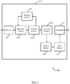
- FIG. 1 a block diagram illustrates an example of a wireless communications system 100.
- the system 100 includes base stations 105 (or cells), mobile devices 115, a base station controller 120, and a core network 125 (the controller 120 may be integrated into the core network 125).
- the system 100 may support operation on multiple carriers (waveform signals of different frequencies).
- the base stations 105 may wirelessly communicate with the mobile devices 115 via a base station antenna (not shown).
- the base stations 105 may communicate with the mobile devices 115 under the control of the base station controller 120 via multiple carriers.
- Each of the base station 105 sites may provide communication coverage for a respective geographic area.
- the coverage area for each base station 105 here is identified as 110-a, 110-b, or 110-c.
- the coverage area for a base station may be divided into sectors (not shown, but making up only a portion of the coverage area).
- the system 100 may include base stations 105 of different types (e.g., macro, micro, and/or pico base stations). There may be overlapping coverage areas for different technologies.
- the mobile devices 115 may be dispersed throughout the coverage areas 110.
- the mobile devices 115 may be referred to as mobile stations, mobile devices, access terminals (ATs), user equipments (UEs), subscriber stations (SSs), or subscriber units.
- the mobile devices 115 may include cellular phones and wireless communications devices, but may also include personal digital assistants (PDAs), other handheld devices, netbooks, notebook computers, etc.
- PDAs personal digital assistants
- the base stations 105 may allow users of the mobile devices 115 to communicate with each other.
- a mobile device 115 may send electronic communications (e.g., email, text message, voicemail messages, etc.) to another mobile device. Users of different mobile devices 115 may also engage in real-time conversations (i.e., phone calls) using their respective devices.
- the mobile devices 115 may each include a configurable biopotential array of electrode tiles.
- the electrode tiles may be arranged in the array in different configurations and with different shapes.
- the array may be embedded along a surface area of the devices 115.
- Biosensors may be incorporated with the electrodes to collect physiological data associated with a user. Electrodes that are in contact with the skin of the user may be activated to begin collecting the data.
- the electrodes in contact with the skin of the user's hand, fingers, etc. may be activated.
- Activated electrodes may be deactivated after contact with the user's skin has terminated.
- the electrodes that are currently activated may be deactivated, and the electrodes that are currently deactivated may be activated.
- the configurable biopotential array of electrode tiles described herein may be implemented on devices in other types of systems, as well.
- FIG. 2 is a block diagram illustrating one example of a mobile device 115-a.
- the mobile device 115-a may be an example of the mobile devices 115 of FIG. 1 .
- the mobile device 115-a may include a receiver 205, a detection module 210, a coupling module 215, a collection module, and a transmitter 225.
- the receiver 205 may receive signals and electronic communications from other devices, such as the base stations 105 or other mobile devices 115.
- the receiver 205 may also receive signals relating to possible contact between the skin of the user of the device 115-a and a surface area of the device 115-a.
- the detection module 210 may analyze the signals relating to the possible contact to determine whether contact exists between the user's skin and a particular surface area of the device 115-a. For example, the detection module 210 may detect contact between the skin of the user and a portion of a biopotential electrode array embedded on the surface area of the device 115. In other words, the detection module 210 may detect contact between the user's skin and at least two or more electrode tiles.
- the coupling module 215 may couple the electrode tiles together that are detected to be in contact with the user's skin.
- each electrode may be connected to the adjacent electrodes with an electronic switch.
- An example of the switch may include a field effect transistor (FET).
- FET field effect transistor
- the electronic switch between these two electrodes may be closed due to electrical conductive properties of the skin, thus creating a closed circuit between the electrodes.
- a closed circuit may activate the electrodes.
- the electronic switch between electrodes that are not in contact with the skin may not be closed, leaving an open circuit. These may be referred to as inactive electrodes.
- the collection module 220 may collect data gathered from the activated electrodes. For example, the module 220 may collect physiological data associated with the user. This data may be gathered via biosensors incorporated with the electrode tiles. As a result, electrodes that are active may collect the data, while inactive electrodes may not participate in gathering the physiological data of the user.
- the configuration biopotential array architecture described herein may minimize electrical noise since electrodes that are inactive (not in contact with the user's skin) are not actively collecting data.
- the mobile device 115-b may be an example of the mobile device of FIG. 1 or 2 .
- the device 115-b may include the receiver 205 and the transmitter 225, as previously described.
- the mobile device 115-b may also include a detection module 210-a, a coupling module 215-a, a collection module 220-a, a comparing module 305, and a selection module 310.
- the detection module 210-a may detect contact between a first group of electrode tiles embedded on an external portion of the device 115-b and the skin of a user of the device 115-b.
- the coupling module 215-a may electrically couple the first group of electrode tiles based on the detection module 210-a detecting contact.
- the first group of coupled electrode tiles may form a first AEA.
- the detection module 210-a may detect contact between the user's skin and a second group of electrode tiles.
- the coupling module 215-a may also electrically couple the second group of electrodes to form a second AEA.
- Each of the electrodes in the first AEA and the second AEA may include a biosensor that may begin collect data regarding the user of the device 115-b.
- the number of AEA may exceed a minimum number of AEAs needed to collect the data.
- the comparing module 305 may compare a signal quality metric associated with each AEA. For example, the comparing module 305 may compare the quality of the electrical signal detected from the skin of the user at each AEA.
- the selection module 310 may select which AEAs to receive data from based on the comparison of the signal quality metrics of each AEA. Examples of the signal quality metric may include, but is not limited to, a signal-to-noise ratio (SNR).
- SNR signal-to-noise ratio
- FIG. 4 is a block diagram illustrating a further example of a mobile device 115-c.
- the mobile device 115-c may be an example of the mobile device 115 of FIG. 1 , 2 , or 3 .
- the device 115-c may include a receiver 205 and a transmitter 225, as mentioned above.
- the mobile device 115-c may also include a detection module 210-b, a coupling module 215-b, a collection module 220-b, a polling module 405, an analysis module 410, and a state module 415.
- the coupling module 215-b may electrically couple electrode tiles when the detection module 210-b detects contact between the electrodes and skin of a user.
- the polling module 405 may routinely poll the coupled electrodes to determine whether the contact with the use's skin is maintained.
- An example of the polling module 405 may be a galvanic skin response (GSR) sensor.
- GSR galvanic skin response
- the polling module 405 may poll the flow of current between adjacent electrodes. If the flow of current between two polled electrodes is zero, the detection module 210-b may detect that the contact with the use's skin no longer exists.
- the coupling module 215-b may decouple the electrodes after the contact with the user's skin is terminated.
- the polling module 405 may also poll the flow of current between previously uncoupled electrodes to determine whether contact with the user's skin may exist. If the flow of current is greater than zero between at least two adjacent electrodes, the detection module 210-b may detect contact between these previously uncoupled electrodes and the skin of the user. The coupling module 220-b may then electrically couple these electrodes.
- the collection module 220-b may collect physiological data of the user via biosensors associated with the electrodes.
- the analysis module 410 may analyze the collected physiological data.
- the state module 415 may determine a state of the user based on the analysis. For example, the state module 415 may determine an emotional state (e.g., happy, excited, sad, angry) for the user based on the analyzed physiological data. The state module 415 may also use the physiological data to determine the physical health of a person.
- An indicator that indicates the determined state of the user may be associated with an electronic communication (e.g., phone call, text message, email, voicemail, etc.).
- the transmitter 225 may transmit the electronic communication and the indicator to a recipient device. In one configuration, the transmitter 225 may transmit the indicator to an application that is used to monitor a person's health. A recipient (such as a doctor, nurse, or other healthcare provider) may access the indicator via the application to monitor the physical health of the person.
- a block diagram 500 illustrates one example of a mobile device 115-d with a biopotential electrode array 505-a embedded on a surface area of the mobile device 115-d.
- the mobile device 115-d may be an example of the mobile device 115 of FIG. 1 , 2 , 3 , or 4 .
- the device 115-d may include a number of surface areas. For example, a side surface area 510, a display surface area, and a bottom surface area 520.
- the array 505-a may be embedded on the side surface area 510 in this example. It is to be understood, however, that the array 505-a may be embedded on other surface areas of the mobile device 115-d.
- the biopotential array 505-a may include a number of electrode tiles 505-a-1 - 505-a- n .
- Each electrode 505-a-1 - 505-a- n may include a biosensor.
- biosensors may include an electrocardiogram (ECG) sensor, a galvanic skin response (GSR) sensor, and other biopotential sensors.
- ECG electrocardiogram
- GSR galvanic skin response
- the electrode tiles 505-a-1 - 505-a- n may be rectangular in shape. A space may exist between each electrode. When current is detected flowing between adjacent electrodes due to contact with human skin, an electronic switch between the electrodes may be closed to create a closed circuit. The closed circuit may allow the electrodes to collect physiological data, while electrodes that are in an open circuit state (are not in contact with human skin) may not participate in collecting the data.
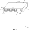
- FIG. 6 is a block diagram 600 illustrating another example of a biopotential array 505-b that includes electrode tiles 505-b-1 - 505-b- n embedded on a surface area of a mobile device 115-e.
- the mobile device 115-e may be an example of the mobile device 115 of FIG. 1 , 2 , 3 , or 4 .
- the device 115-e may include a side surface area 510, a display surface area 515, and a bottom surface area 520.
- the biopotential array 505-b may be embedded along the side surface area 510 in this example.
- the electrode tiles 505-b-1 - 505-b- n may be hexagonal in shape. As illustrated, a space may not exist between adjacent electrodes.
- Each electrode may include a biosensor to collect information about the user. The biosensors may begin to collect the data when their respective electrodes are in contact with the skin of a user.
- the electrode tiles may be examples of the electrodes of FIG. 5 or 6 .
- an electronic switch 705-a-1, 705-a-2, and 705-a-3 may exist between each adjacent electrode tile.
- the electronic switch between the at least two electrodes may be closed due to the flow of current between the at least two adjacent electrodes.
- the biosensors associated with the at least two electrodes may begin to collect physiological data associated with the user. For example, the user may touch a first electrode tile 505-b-1 and a second electrode tile 505-b-2.
- the electrodes When contact with the user's skin is detected, the electrodes may be electrically coupled by closing the electronic switch 705-a-2 between them. With the switch closed, the biosensors associated with the first and second electrodes 505-b-1, 505-b-2 may collect data about the user. The switch 705-a-2 may be opened (and the electrodes uncoupled) when contact between the electrodes and the skin is terminated.
- FIG. 8 is a block diagram 800 illustrating a biopotential electrode array 505-b embedded on a mobile device 115-f with a number of AEAs 805-a-1, 805-a-2.
- the mobile device 115-f may be an example of the mobile device 115 of FIGS. 1 , 2 , 3 , 4 , 5 , of 6.
- the device 115-f may include a number of surface areas.
- the device may include a display surface area 515, a bottom surface area 520, and a side surface area 510.
- the array 505-b may be embedded on the side surface area 510 of the mobile device 115-f. It is to be understood that the array 505-b may be embedded on other surface areas of the device in addition to, or in place of, the side surface area 510.
- the array 505-b may include a first AEA 805-a-1 and a second AEA 805-a-2.
- Each AEA may include at least two electrode tiles that have been electrically coupled.
- each AEA may include electrode tiles that are in contact with the skin of a user.
- the position of one or both AEAs may also change. For example, at a first time period, the user may be holding the device 115-f so that his/her skin is in contact with the electrodes in the first AEA 805-a-1 and the second AEA 805-a-2.
- the electrode tiles in these AEAs may collect physiological data associated with the user while they are activated ( i.e., in contact with the user's skin).
- the user may change the position of his/her grip of the device 115-f.
- the user may no longer be in contact with the electrodes in the first AEA 805-a-1.
- These electrodes may be deactivated and the first AEA 805-a-1 may cease to exist..
- Physiological data may still be collected during the second time period via the electrodes of the second AEA 805-a-2, if the user continues to touch this portion of the array 505-b. If the user grips a previously untouched portion of the array 505-b, the electrodes in this portion may be coupled and a new AEA may be formed.
- the AEAs may be dynamically changed. For example, as the user shifts his/her grip on the side surface area 510 of the mobile device 115-f, the position and number of AEAs may also change.
- the polling module 405 may continuously poll the flow of current between adjacent electrodes to determine which contiguous areas remain active and which inactive areas of the array 505-b should be activated. This architecture allows the collection of the physiological data to occur while the user adjusts his/her grip on the device 115-f (as long as at least a portion of the skin is contacting the array 505-b).
- the method 900 may be implemented by a mobile device, such as the mobile device 115 of FIG. 1 , 2 , 3 , 4 , 5 , 6 , or 8 .
- the method 900 may be implemented by the detection module 210, the coupling module 215, and the collection module 220 of FIG. 2 .
- the biopotential electrode array may be embedded on a surface area of the mobile device 115.
- the array may include a number of electrode tiles.
- Each electrode may be associated with a biosensor to collect information about a user, such as physiological information.
- contact between at least two adjacent electrode tiles of the biopotential electrode array and skin of a user may be detected.
- the at least two adjacent electrodes may be electrically coupled when the contact is detected.
- an electronic switch between the at least two adjacent electrodes may be closed when the user touches the electrodes.
- the electrically coupled electrodes may form a first AEA.
- physiological data associated with the user may be collected via the coupled electrode tiles in the first AEA. Uncoupled electrodes in the biopotential electrode array may not participate in the collection of the physiological data associated with the user.
- the method 900 may provide for collecting physiological data using a dynamically configurable biopotential electrode array embedded on the mobile device 115.
- FIG. 10 is an example of a method 1000 to determine whether to maintain an electric coupling of at least two electrode tiles within a configurable biopotential electrode array.
- the method 1000 may be implemented by a mobile device, such as the mobile device 115 of FIG. 1 , 2 , 3 , 4 , 5 , 6 , or 8 .
- the method 1000 may be implemented by the detection module 210-b, the coupling module 215-b, the collection module 220-b, and the polling module 405 of FIG. 4 .
- the biopotential electrode array (including a number of electrode tiles) may be included on a external portion of the mobile device 115.
- contact between at least two adjacent electrode tiles and skin of a user may be detected.
- the at least two adjacent electrode tiles may be coupled when contact is detected.
- the coupled electrodes may form a first AEA.
- a determination may be made as to whether the contact between the user's skin and the electrodes is maintained.
- the polling module 405 may poll the coupled electrodes to determine whether the flow of current between the electrodes is greater than zero.
- physiological data may be collected by the coupled electrode tiles of the first AEA at block 1020.
- the electrodes may include biosensors to collect the data.
- the method 1000 may then return to determine whether the contact persists by continuing to poll the coupled electrodes. If, however, it is determined that the contact is terminated, the at least two adjacent electrode tiles may be decoupled at block 1025. The uncoupled electrodes may cease to collect physiological data associated with the user. The method 1000 may then return to continue to detect whether adjacent electrodes are in contact with the user's skin.
- the method 1000 may determine whether contact is maintained between electrode tiles and the skin of the user. It should be noted that the method 1000 is just one implementation and that operations of the method 1000 may be rearranged or otherwise modified such that other implementations are possible.
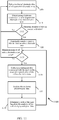
- a flow chart illustrates one example of a method 1100 to poll electrode tiles of a dynamically configurable biopotential electrode array to detect contact between skin of a user and at least two of the electrodes.
- the method 1100 may be implemented by a mobile device, such as the mobile device 115 of FIG. 1 , 2 , 3 , 4 , 5 , 6 , or 8 .
- the method 1100 may be implemented by the detection module 210-b, the coupling module 215-b, the collection module 220-b, the polling module 405, the analysis module 410, and the state module 415 of FIG. 4 .
- a number of electrode tiles of a biopotential electrode array may be polled. For example, the current flow between adjacent electrodes may be polled to determine whether the flow is greater than zero.
- the array may be embedded on an external surface area of the mobile device 115.
- contact between electrode tiles and the skin of a user of the mobile device 115 may be detected.
- a determination may be made as to whether a minimum number of electrodes are in contact with the skin. If it is determined that a minimum number of electrodes are not in contact with the user's skin, the method 1100 may return to continue to poll electrode tiles to detect contact. If, however, it is determined that a minimum number of electrodes are in contact with the skin, at block 1120, the electrode tiles in contact with the skin may be electrically coupled to form an AEA.
- a determination may be made as to whether a minimum number of AEAs exist. For example, certain types of physiological data may be gathered from a minimum number of AEAs. As an example, to collect GSR data, at least two AEAs may be used, while at least three AEAs may be used to collect electrocardiogram data. If it is determined that a minimum number of AEAs do not exist to collect the desired physiological data, the method 1100 may return to poll electrodes within the array to detect contact. If, however it is determined that a minimum number of AEAs exist, at block 1130, the physiological data may be collected via the electrodes of the AEAs. While the data is being collected, the polling module 405 may continue to poll electrodes in real time in order to detect whether the contact is maintained between the currently coupled electrodes as well as whether contact is detected between the skin and previously uncoupled electrodes.
- the collected data may be analyzed.
- a state of the user may be determined based on the analysis. For example, an emotional state, a state of physical health, etc. of the user may be determined based on the analyzed physiological data.
- the method 1100 may return to determine whether the minimum number of AEAs still exists. If the AEAs are maintained, physiological data may continue to be collected via biosensors associated with the electrodes in the AEAs.
- the method 1100 may poll electrode tiles of a dynamically configurable biopotential electrode array to detect contact between skin of a user and the electrode tiles.
- a biopotential array of electrode tiles may be embedded on an external surface area of the mobile device 115.
- the electrodes may be associated with biosensors used to collect physiological data relating to a user of the mobile device 115.
- the electrodes may be decoupled from each other until they come into contact with the user's skin. Decoupled electrodes may not be activated to collect physiological data associated with a user of the device 115.
- an electronic switch between adjacent electrodes may close, thus electrically coupling the electrodes in contact with the skin.
- the biosensors associated with these coupled electrodes may then begin to collect physiological data about the user.
- the coupled electrodes may be decoupled if contact with the skin does not persist.
- Previously uncoupled electrodes that may now be in contact with the skin, may be electrically coupled to begin collecting the data.
- Information and signals may be represented using any of a variety of different technologies and techniques.
- data, instructions, commands, information, signals, bits, symbols, and chips that may be referenced throughout the above description may be represented by voltages, currents, electromagnetic waves, magnetic fields or particles, optical fields or particles, or any combination thereof.
- DSP digital signal processor
- ASIC application specific integrated circuit
- FPGA field programmable gate array
- a general-purpose processor may be a microprocessor, but in the alternative, the processor may be any conventional processor, controller, microcontroller, or state machine.
- a processor may also be implemented as a combination of computing devices, e.g., a combination of a DSP and a microprocessor, multiple microprocessors, one or more microprocessors in conjunction with a DSP core, or any other such configuration.
- the functions described herein may be implemented in hardware, software executed by a processor, firmware, or any combination thereof. If implemented in software executed by a processor, the functions may be stored on or transmitted over as one or more instructions or code on a computer-readable medium. Other examples and implementations are within the scope of the invention as defined by the appended claims. For example, due to the nature of software, functions described above can be implemented using software executed by a processor, hardware, firmware, hardwiring, or combinations of any of these. Features implementing functions may also be physically located at various positions, including being distributed such that portions of functions are implemented at different physical locations.
- Computer-readable media includes both computer storage media and communication media including any medium that facilitates transfer of a computer program from one place to another.
- a storage medium may be any available medium that can be accessed by a general purpose or special purpose computer.
- computer-readable media can comprise RAM, ROM, EEPROM, CD-ROM or other optical disk storage, magnetic disk storage or other magnetic storage devices, or any other medium that can be used to carry or store desired program code means in the form of instructions or data structures and that can be accessed by a general-purpose or special-purpose computer, or a general-purpose or special-purpose processor.
- Disk and disc include compact disc (CD), laser disc, optical disc, digital versatile disc (DVD), floppy disk and blu-ray disc where disks usually reproduce data magnetically, while discs reproduce data optically with lasers. Combinations of the above are also included within the scope of computer-readable media.
Description
- Wireless communication systems are widely deployed to provide various types of electronic communication content such as voice, data, and so on. While electronic forms of communication (e.g., email, text messages, voicemail, phone calls) have enabled people to conveniently contact and interact with others, the richness of electronic communications is attenuated.
- Electronic communications, by themselves, do not generally convey the full emotional state of the sender. For example, research suggests that 7% of emotional context in a given message is conveyed by the words (e.g., text in an electronic communications). Another 38% of the emotional context is conveyed vocally by the tone of the voice. The final 55% is expressed using non-verbal communication, such as facial expression and other body gestures (Mehrabian, Albert; Ferris, Susan R. (1967). "Inference of Attitudes from Nonverbal Communication in Two Channels". Journal of Consulting Psychology 31 (3): 248-252). With regards to electronic communications, the emotional context or emotional state of the sender is commonly misinterpreted by the receiver.
- Biopotential electrodes may be used with biosensors to collect physiological data from the human body. The physiological data may be used to determine an emotional state of a person. In addition, the biosensors may be used to monitor the physical health of a person. The biosensor may convert a biological response into an electrical signal. Typically, these electrodes that include biosensors are a standard shape and size (e.g., 8 mm flat disc). The electrical signals generated from the biological response are relatively small. As a result, even a small amount of noise may significantly interfere with the electrical signal. This may cause the determined emotional or physiological state of the person to be inaccurate or unknown.
- A biopotential electrode with a large surface area may increase the amount of noise that may cause interference with the electrical signals created by the biosensors.
- On the other hand, a biopotential electrode with too small of a surface area may render the reading of electrical signals associated with physiological data impractical.
- Attention is drawn to
WO 2011/022068 A1 which describes a device for determining muscle condition of a region of tissue. The device comprises an electrical impedance myography, EIM, portable probe bearing an electrode array. The electrode array comprises excitation electrodes used to apply multi-frequency electrical signals to the region of tissue and pickup electrodes that are used to collect electrical signals resulting from the application of the multi-frequency electrical signals to the region of tissue. To improve accuracy and reproducibility of EIM measurements, the electrode array is reconfigurable to select different subsets of excitation and pickup electrodes so that the electrodes are oriented differently with respect to muscle fibers. Additional devices may be associated with the EIM probe to measure such parameters as temperature, moisture content of the region, quality of contact of electrodes of the electrode array with a surface of the region and pressure with which the EEM probe is applied to the region. The EIM measurements may be adjusted based on these parameters. Also, ultrasound and electrical impedance tomography measurements may supplement the ELM measurements for more complete analysis of the muscle condition. - Attention is further drawn to
WO 2006/131855 A2 which relates to a patient monitoring system for monitoring cardio pulmonary performance or the like by means of capacitive measurement. Further the invention relates to a method for monitoring cardio pulmonary performance or the like by means of a capacitive measurement. In order to provide a reliable technique for monitoring cardio pulmonary performance or the like, which technique is particularly suitable for home use, a patient monitoring system for monitoring cardio pulmonary performance or the like by means of capacitive measurement is suggested, said system comprising a number of electrodes arranged in the form of a matrix, said electrodes being adapted to be integrated with a bed or the like, each electrode being individually selectable, means for determining a number of electrodes; depending on the position of the patient on the bed or the like, said means being adapted to determine the number of electrodes by determining the capacitance of a number of electrodes, and means for selecting a number of said determined electrodes for carrying out a capacitive measurement. - In accordance with the present invention a method, and a system, as set forth in the independent claims, respectively, are provided. A corresponding computer program product is defined in claim 15. Preferred embodiments of the invention are described in the dependent claims.
- Methods, systems, and devices are described for collecting physiological data using a configurable biopotential array. In one example, the array is embedded on an external surface area of a handheld device. The array may include a number of electrode tiles that are associated with biosensors to collect the physiological data of a user. The electrodes may be polled to detect whether the electrodes are in contact with the user's skin. Electrodes that are in contact with the skin are electrically coupled to form an active electrode area. The biosensors associated with the coupled electrodes may collect the physiological data relating to the user. The coupled electrodes may be continuously polled to detect whether the contact with the user's skin is maintained. In addition, uncoupled electrodes in the array are continuously polled to detect contact. Coupled electrodes may be decoupled after contact with the user's skin is terminated. The collected physiological data may be analyzed and a state of the user may be determined from the analyzed data.
- In one configuration, uncoupled electrode tiles in the array may be electrically coupled based on detecting contact to form a second active electrode area. Physiological data associated with the user may be collected via the coupled electrode tiles of the second active electrode area. In one example, a first active electrode area and the second active electrode area may exist nonconcurrenlty within the biopotential electrode array.
- In one configuration, a determination may be made as to whether a minimum number of active electrode areas exist within the biopotential electrode array. Physiological data associated with the user may be collected based on the determination that the minimum number of active electrode areas exist.
- In accordance with the invention, a plurality of active electrode areas are detected within the biopotential electrode array. Signal qualities associated with each of the plurality of active electrode areas are compared. At least one of the plurality of active electrode areas is selected to collected physiological data based on the comparison of signal qualities.
- The biosensors associated with the electrode tiles may include an electrocardiogram sensor (ECG) or a galvanic skin response (GSR) sensor.
- A communications device configured to collect physiological data using a dynamically configurable biopotential electrode array, a system configured to collect physiological data using a dynamically configurable biopotential electrode array, and a computer program product configured to collect physiological data using a dynamically configurable biopotential electrode array are also described. The product may include non-transitory computer-readable medium. The medium may include code to detect contact between at least two adjacent electrode tiles of the biopotential electrode array and skin of a user. The medium may further include code to electrically couple at least two adjacent electrode tiles, based on detecting contact. The coupled electrode tiles may form a first active electrode area within the biopotential electrode array. The medium may also include code to collect physiological data associated with the user via the coupled electrode tiles of the first active electrode area.
- A further understanding of the nature of the present invention may be realized by reference to the following drawings. In the appended figures, similar components or features may have the same reference label. Further, various components of the same type may be distinguished by following the reference label by a dash and a second label that distinguishes among the similar components. If only the first reference label is used in the specification, the description is applicable to any one of the similar components having the same first reference label irrespective of the second reference label.
-
FIG. 1 shows a block diagram of a wireless communications system; -
FIG. 2 is a block diagram illustrating one example of a mobile device; -
FIG. 3 is a block diagram illustrating another example of the mobile device; -
FIG. 4 is a block diagram illustrating a further example of the mobile device; -
FIG. 5 a block diagram illustrates one example of a mobile device with a biopotential electrode array embedded on a surface area of the device; -
FIG. 6 is a block diagram illustrating another example of a biopotential array including electrode tiles embedded on a surface area of a mobile device; -
FIG. 7 illustrates an example of an electrode tile; -
FIG. 8 is a block diagram illustrating a biopotential electrode array with a number of active electrode areas; -
FIG. 9 is a flow chart illustrating one example of a method to collect physiological data using a dynamically configurable biopotential electrode array; -
FIG. 10 is a flow chart illustrating one example of a method to determine whether to maintain an electric coupling of at least two electrode tiles within a configurable biopotential electrode array; and -
FIG. 11 is a flow chart illustrating one example of a method to poll electrode tiles of a dynamically configurable biopotential electrode array to detect contact between skin of a user and at least two of the electrodes. - A configurable biopotential electrode array is described. The array may be used to collect physiological data about a user. In one example, the array may be embedded on a surface area of a device, such as a handheld electronic communications device. The array includes a number of electrode tiles (also referred to as "electrodes"). The electrodes may include biosensors that collect the physiological data of a user of the device. In one configuration, the electrodes (and their associated biosensors) may be activated to begin collecting the data when contact is detected between the electrodes and the skin of the user. The electrodes may be deactivated after contact between the electrodes and the skin of the user is terminated. A deactivated electrode may not collect the physiological data.
- A contiguous area of a number of activated electrodes may function as a single electrode. The contiguous area may be referred to as an active electrode area (AEA). The electrodes within an AEA may collect physiological data of the user. The array may include one or more AEAs located at different positions along the array. For example, skin of the user may be in contact with a first group of electrodes (forming a first AEA) and a separate, second group of electrodes (forming a second AEA). The first AEA and the second AEA may not be adjacent to one another along the array. In addition, the first AEA and the second AEA may exist concurrently or nonconcurrently within the biopotential electrode array.
- In one configuration, the electrodes of the array may be routinely polled to determine whether they are in contact with the skin of the user, or, if contact already exists, whether the contact between the skin of the user and the electrodes is maintained. The physiological data collected by the biosensors of the electrodes may be analyzed to determine an emotional state of the user or a health status of the user.
- Thus, the following description provides examples, and is not limiting of the scope of the invention as defined in the claims. Changes may be made in the function and arrangement of elements discussed without departing from the scope of the invention as defined in the claims.
- Referring first to
FIG. 1 , a block diagram illustrates an example of awireless communications system 100. Thesystem 100 includes base stations 105 (or cells),mobile devices 115, abase station controller 120, and a core network 125 (thecontroller 120 may be integrated into the core network 125). Thesystem 100 may support operation on multiple carriers (waveform signals of different frequencies). - The
base stations 105 may wirelessly communicate with themobile devices 115 via a base station antenna (not shown). Thebase stations 105 may communicate with themobile devices 115 under the control of thebase station controller 120 via multiple carriers. Each of thebase station 105 sites may provide communication coverage for a respective geographic area. The coverage area for eachbase station 105 here is identified as 110-a, 110-b, or 110-c. The coverage area for a base station may be divided into sectors (not shown, but making up only a portion of the coverage area). Thesystem 100 may includebase stations 105 of different types (e.g., macro, micro, and/or pico base stations). There may be overlapping coverage areas for different technologies. - The
mobile devices 115 may be dispersed throughout thecoverage areas 110. Themobile devices 115 may be referred to as mobile stations, mobile devices, access terminals (ATs), user equipments (UEs), subscriber stations (SSs), or subscriber units. Themobile devices 115 may include cellular phones and wireless communications devices, but may also include personal digital assistants (PDAs), other handheld devices, netbooks, notebook computers, etc. - The
base stations 105 may allow users of themobile devices 115 to communicate with each other. For example, amobile device 115 may send electronic communications (e.g., email, text message, voicemail messages, etc.) to another mobile device. Users of differentmobile devices 115 may also engage in real-time conversations (i.e., phone calls) using their respective devices. Themobile devices 115 may each include a configurable biopotential array of electrode tiles. The electrode tiles may be arranged in the array in different configurations and with different shapes. The array may be embedded along a surface area of thedevices 115. Biosensors may be incorporated with the electrodes to collect physiological data associated with a user. Electrodes that are in contact with the skin of the user may be activated to begin collecting the data. For example, as the user holds themobile device 115 in his/her hand, the electrodes in contact with the skin of the user's hand, fingers, etc. may be activated. Activated electrodes may be deactivated after contact with the user's skin has terminated. For example, as the user changes the position of his/her grip of thedevice 115, the electrodes that are currently activated may be deactivated, and the electrodes that are currently deactivated may be activated. The configurable biopotential array of electrode tiles described herein may be implemented on devices in other types of systems, as well. -
FIG. 2 is a block diagram illustrating one example of a mobile device 115-a. The mobile device 115-a may be an example of themobile devices 115 ofFIG. 1 . In one configuration, the mobile device 115-a may include areceiver 205, adetection module 210, acoupling module 215, a collection module, and atransmitter 225. Thereceiver 205 may receive signals and electronic communications from other devices, such as thebase stations 105 or othermobile devices 115. Thereceiver 205 may also receive signals relating to possible contact between the skin of the user of the device 115-a and a surface area of the device 115-a. In one example, thedetection module 210 may analyze the signals relating to the possible contact to determine whether contact exists between the user's skin and a particular surface area of the device 115-a. For example, thedetection module 210 may detect contact between the skin of the user and a portion of a biopotential electrode array embedded on the surface area of thedevice 115. In other words, thedetection module 210 may detect contact between the user's skin and at least two or more electrode tiles. - The
coupling module 215 may couple the electrode tiles together that are detected to be in contact with the user's skin. For example, each electrode may be connected to the adjacent electrodes with an electronic switch. An example of the switch may include a field effect transistor (FET). When a particular electrode tile and at least one adjacent electrode tile comes in contact with the skin, the electronic switch between these two electrodes may be closed due to electrical conductive properties of the skin, thus creating a closed circuit between the electrodes. A closed circuit may activate the electrodes. The electronic switch between electrodes that are not in contact with the skin may not be closed, leaving an open circuit. These may be referred to as inactive electrodes. - The
collection module 220 may collect data gathered from the activated electrodes. For example, themodule 220 may collect physiological data associated with the user. This data may be gathered via biosensors incorporated with the electrode tiles. As a result, electrodes that are active may collect the data, while inactive electrodes may not participate in gathering the physiological data of the user. The configuration biopotential array architecture described herein may minimize electrical noise since electrodes that are inactive (not in contact with the user's skin) are not actively collecting data. - Referring now to
FIG. 3 , a block diagram illustrates another example of a mobile device 115-b. The mobile device 115-b may be an example of the mobile device ofFIG. 1 or2 . The device 115-b may include thereceiver 205 and thetransmitter 225, as previously described. The mobile device 115-b may also include a detection module 210-a, a coupling module 215-a, a collection module 220-a, a comparingmodule 305, and aselection module 310. The detection module 210-a may detect contact between a first group of electrode tiles embedded on an external portion of the device 115-b and the skin of a user of the device 115-b. The coupling module 215-a may electrically couple the first group of electrode tiles based on the detection module 210-a detecting contact. In one configuration, the first group of coupled electrode tiles may form a first AEA. In one example, the detection module 210-a may detect contact between the user's skin and a second group of electrode tiles. The coupling module 215-a may also electrically couple the second group of electrodes to form a second AEA. Each of the electrodes in the first AEA and the second AEA may include a biosensor that may begin collect data regarding the user of the device 115-b. In one example, the number of AEA may exceed a minimum number of AEAs needed to collect the data. The comparingmodule 305 may compare a signal quality metric associated with each AEA. For example, the comparingmodule 305 may compare the quality of the electrical signal detected from the skin of the user at each AEA. Theselection module 310 may select which AEAs to receive data from based on the comparison of the signal quality metrics of each AEA. Examples of the signal quality metric may include, but is not limited to, a signal-to-noise ratio (SNR). -
FIG. 4 is a block diagram illustrating a further example of a mobile device 115-c. The mobile device 115-c may be an example of themobile device 115 ofFIG. 1 ,2 , or3 . The device 115-c may include areceiver 205 and atransmitter 225, as mentioned above. The mobile device 115-c may also include a detection module 210-b, a coupling module 215-b, a collection module 220-b, apolling module 405, ananalysis module 410, and astate module 415. In one example, the coupling module 215-b may electrically couple electrode tiles when the detection module 210-b detects contact between the electrodes and skin of a user. - In one configuration, the
polling module 405 may routinely poll the coupled electrodes to determine whether the contact with the use's skin is maintained. An example of thepolling module 405 may be a galvanic skin response (GSR) sensor. When skin contacts the electrodes, the current between the contacted electrodes may be greater than zero, due to the conductive properties of the skin. As a result, thepolling module 405 may poll the flow of current between adjacent electrodes. If the flow of current between two polled electrodes is zero, the detection module 210-b may detect that the contact with the use's skin no longer exists. The coupling module 215-b may decouple the electrodes after the contact with the user's skin is terminated. Thepolling module 405 may also poll the flow of current between previously uncoupled electrodes to determine whether contact with the user's skin may exist. If the flow of current is greater than zero between at least two adjacent electrodes, the detection module 210-b may detect contact between these previously uncoupled electrodes and the skin of the user. The coupling module 220-b may then electrically couple these electrodes. - While coupled electrodes remain in contact with the user's skin, the collection module 220-b may collect physiological data of the user via biosensors associated with the electrodes. The
analysis module 410 may analyze the collected physiological data. In one configuration, thestate module 415 may determine a state of the user based on the analysis. For example, thestate module 415 may determine an emotional state (e.g., happy, excited, sad, angry) for the user based on the analyzed physiological data. Thestate module 415 may also use the physiological data to determine the physical health of a person. An indicator that indicates the determined state of the user may be associated with an electronic communication (e.g., phone call, text message, email, voicemail, etc.). Thetransmitter 225 may transmit the electronic communication and the indicator to a recipient device. In one configuration, thetransmitter 225 may transmit the indicator to an application that is used to monitor a person's health. A recipient (such as a doctor, nurse, or other healthcare provider) may access the indicator via the application to monitor the physical health of the person. - Referring now to
FIG. 5 , a block diagram 500 illustrates one example of a mobile device 115-d with a biopotential electrode array 505-a embedded on a surface area of the mobile device 115-d. In one configuration, the mobile device 115-d may be an example of themobile device 115 ofFIG. 1 ,2 ,3 , or4 . The device 115-d may include a number of surface areas. For example, aside surface area 510, a display surface area, and abottom surface area 520. The array 505-a may be embedded on theside surface area 510 in this example. It is to be understood, however, that the array 505-a may be embedded on other surface areas of the mobile device 115-d. In one example, the biopotential array 505-a may include a number of electrode tiles 505-a-1 - 505-a-n. Each electrode 505-a-1 - 505-a-n may include a biosensor. Examples of biosensors may include an electrocardiogram (ECG) sensor, a galvanic skin response (GSR) sensor, and other biopotential sensors. As illustrated, the electrode tiles 505-a-1 - 505-a-n may be rectangular in shape. A space may exist between each electrode. When current is detected flowing between adjacent electrodes due to contact with human skin, an electronic switch between the electrodes may be closed to create a closed circuit. The closed circuit may allow the electrodes to collect physiological data, while electrodes that are in an open circuit state (are not in contact with human skin) may not participate in collecting the data. -
FIG. 6 , is a block diagram 600 illustrating another example of a biopotential array 505-b that includes electrode tiles 505-b-1 - 505-b-n embedded on a surface area of a mobile device 115-e. The mobile device 115-e may be an example of themobile device 115 ofFIG. 1 ,2 ,3 , or4 . In one example, the device 115-e may include aside surface area 510, adisplay surface area 515, and abottom surface area 520. The biopotential array 505-b may be embedded along theside surface area 510 in this example. The electrode tiles 505-b-1 - 505-b-n may be hexagonal in shape. As illustrated, a space may not exist between adjacent electrodes. Each electrode may include a biosensor to collect information about the user. The biosensors may begin to collect the data when their respective electrodes are in contact with the skin of a user. - Referring now to
FIG. 7 , acollection 700 of electrode tiles 505-b-1, 505-b-2, 505-b-3 are illustrated. The electrode tiles may be examples of the electrodes ofFIG. 5 or6 . In one example, an electronic switch 705-a-1, 705-a-2, and 705-a-3 may exist between each adjacent electrode tile. When the skin of a user contacts at least two adjacent electrodes, the electronic switch between the at least two electrodes may be closed due to the flow of current between the at least two adjacent electrodes. The biosensors associated with the at least two electrodes may begin to collect physiological data associated with the user. For example, the user may touch a first electrode tile 505-b-1 and a second electrode tile 505-b-2. When contact with the user's skin is detected, the electrodes may be electrically coupled by closing the electronic switch 705-a-2 between them. With the switch closed, the biosensors associated with the first and second electrodes 505-b-1, 505-b-2 may collect data about the user. The switch 705-a-2 may be opened (and the electrodes uncoupled) when contact between the electrodes and the skin is terminated. -
FIG. 8 is a block diagram 800 illustrating a biopotential electrode array 505-b embedded on a mobile device 115-f with a number of AEAs 805-a-1, 805-a-2. The mobile device 115-f may be an example of themobile device 115 ofFIGS. 1 ,2 ,3 ,4 ,5 , of 6. In one configuration, the device 115-f may include a number of surface areas. For example, the device may include adisplay surface area 515, abottom surface area 520, and aside surface area 510. In one example, the array 505-b may be embedded on theside surface area 510 of the mobile device 115-f. It is to be understood that the array 505-b may be embedded on other surface areas of the device in addition to, or in place of, theside surface area 510. - In one configuration, the array 505-b may include a first AEA 805-a-1 and a second AEA 805-a-2. Each AEA may include at least two electrode tiles that have been electrically coupled. In other words, each AEA may include electrode tiles that are in contact with the skin of a user. As the user's grip of the device 115-f shifts along the
side surface area 510, the position of one or both AEAs may also change. For example, at a first time period, the user may be holding the device 115-f so that his/her skin is in contact with the electrodes in the first AEA 805-a-1 and the second AEA 805-a-2. The electrode tiles in these AEAs may collect physiological data associated with the user while they are activated (i.e., in contact with the user's skin). At a second time period, the user may change the position of his/her grip of the device 115-f. As a result, the user may no longer be in contact with the electrodes in the first AEA 805-a-1. These electrodes may be deactivated and the first AEA 805-a-1 may cease to exist.. Physiological data may still be collected during the second time period via the electrodes of the second AEA 805-a-2, if the user continues to touch this portion of the array 505-b. If the user grips a previously untouched portion of the array 505-b, the electrodes in this portion may be coupled and a new AEA may be formed. - As illustrated in this example, the AEAs may be dynamically changed. For example, as the user shifts his/her grip on the
side surface area 510 of the mobile device 115-f, the position and number of AEAs may also change. Thepolling module 405 may continuously poll the flow of current between adjacent electrodes to determine which contiguous areas remain active and which inactive areas of the array 505-b should be activated. This architecture allows the collection of the physiological data to occur while the user adjusts his/her grip on the device 115-f (as long as at least a portion of the skin is contacting the array 505-b). - Referring now to
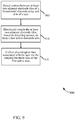
FIG. 9 , a flow chart is provided illustrating one example of amethod 900 to collect physiological data using a dynamically configurable biopotential electrode array. Themethod 900 may be implemented by a mobile device, such as themobile device 115 ofFIG. 1 ,2 ,3 ,4 ,5 ,6 , or8 . In one configuration, themethod 900 may be implemented by thedetection module 210, thecoupling module 215, and thecollection module 220 ofFIG. 2 . - In one example, the biopotential electrode array may be embedded on a surface area of the
mobile device 115. The array may include a number of electrode tiles. Each electrode may be associated with a biosensor to collect information about a user, such as physiological information. Atblock 905, contact between at least two adjacent electrode tiles of the biopotential electrode array and skin of a user may be detected. Atblock 910, the at least two adjacent electrodes may be electrically coupled when the contact is detected. For example, an electronic switch between the at least two adjacent electrodes may be closed when the user touches the electrodes. The electrically coupled electrodes may form a first AEA. Atblock 915, physiological data associated with the user may be collected via the coupled electrode tiles in the first AEA. Uncoupled electrodes in the biopotential electrode array may not participate in the collection of the physiological data associated with the user. - Therefore, the
method 900 may provide for collecting physiological data using a dynamically configurable biopotential electrode array embedded on themobile device 115. -
FIG. 10 is an example of amethod 1000 to determine whether to maintain an electric coupling of at least two electrode tiles within a configurable biopotential electrode array. Themethod 1000 may be implemented by a mobile device, such as themobile device 115 ofFIG. 1 ,2 ,3 ,4 ,5 ,6 , or8 . In one configuration, themethod 1000 may be implemented by the detection module 210-b, the coupling module 215-b, the collection module 220-b, and thepolling module 405 ofFIG. 4 . - In one example, the biopotential electrode array (including a number of electrode tiles) may be included on a external portion of the
mobile device 115. Atblock 1005, contact between at least two adjacent electrode tiles and skin of a user may be detected. Atblock 1010, the at least two adjacent electrode tiles may be coupled when contact is detected. The coupled electrodes may form a first AEA. In one configuration, atblock 1015, a determination may be made as to whether the contact between the user's skin and the electrodes is maintained. For example, thepolling module 405 may poll the coupled electrodes to determine whether the flow of current between the electrodes is greater than zero. If it is determined that the contact is maintained (i.e., flow of current is greater than zero), physiological data may be collected by the coupled electrode tiles of the first AEA atblock 1020. The electrodes may include biosensors to collect the data. Themethod 1000 may then return to determine whether the contact persists by continuing to poll the coupled electrodes. If, however, it is determined that the contact is terminated, the at least two adjacent electrode tiles may be decoupled atblock 1025. The uncoupled electrodes may cease to collect physiological data associated with the user. Themethod 1000 may then return to continue to detect whether adjacent electrodes are in contact with the user's skin. - Therefore, the
method 1000 may determine whether contact is maintained between electrode tiles and the skin of the user. It should be noted that themethod 1000 is just one implementation and that operations of themethod 1000 may be rearranged or otherwise modified such that other implementations are possible. - Referring now to
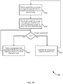
FIG. 11 , a flow chart illustrates one example of amethod 1100 to poll electrode tiles of a dynamically configurable biopotential electrode array to detect contact between skin of a user and at least two of the electrodes. Themethod 1100 may be implemented by a mobile device, such as themobile device 115 ofFIG. 1 ,2 ,3 ,4 ,5 ,6 , or8 . In one configuration, themethod 1100 may be implemented by the detection module 210-b, the coupling module 215-b, the collection module 220-b, thepolling module 405, theanalysis module 410, and thestate module 415 ofFIG. 4 . - At
block 1105, a number of electrode tiles of a biopotential electrode array may be polled. For example, the current flow between adjacent electrodes may be polled to determine whether the flow is greater than zero. In one configuration, the array may be embedded on an external surface area of themobile device 115. Atblock 1110, contact between electrode tiles and the skin of a user of themobile device 115 may be detected. Atblock 1115, a determination may be made as to whether a minimum number of electrodes are in contact with the skin. If it is determined that a minimum number of electrodes are not in contact with the user's skin, themethod 1100 may return to continue to poll electrode tiles to detect contact. If, however, it is determined that a minimum number of electrodes are in contact with the skin, atblock 1120, the electrode tiles in contact with the skin may be electrically coupled to form an AEA. - At
block 1125, a determination may be made as to whether a minimum number of AEAs exist. For example, certain types of physiological data may be gathered from a minimum number of AEAs. As an example, to collect GSR data, at least two AEAs may be used, while at least three AEAs may be used to collect electrocardiogram data. If it is determined that a minimum number of AEAs do not exist to collect the desired physiological data, themethod 1100 may return to poll electrodes within the array to detect contact. If, however it is determined that a minimum number of AEAs exist, atblock 1130, the physiological data may be collected via the electrodes of the AEAs. While the data is being collected, thepolling module 405 may continue to poll electrodes in real time in order to detect whether the contact is maintained between the currently coupled electrodes as well as whether contact is detected between the skin and previously uncoupled electrodes. - At
block 1135, the collected data may be analyzed. Atblock 1140, a state of the user may be determined based on the analysis. For example, an emotional state, a state of physical health, etc. of the user may be determined based on the analyzed physiological data. Themethod 1100 may return to determine whether the minimum number of AEAs still exists. If the AEAs are maintained, physiological data may continue to be collected via biosensors associated with the electrodes in the AEAs. - Therefore, the
method 1100 may poll electrode tiles of a dynamically configurable biopotential electrode array to detect contact between skin of a user and the electrode tiles. - As provided by the description above, a biopotential array of electrode tiles may be embedded on an external surface area of the
mobile device 115. The electrodes may be associated with biosensors used to collect physiological data relating to a user of themobile device 115. The electrodes may be decoupled from each other until they come into contact with the user's skin. Decoupled electrodes may not be activated to collect physiological data associated with a user of thedevice 115. When contact is detected, an electronic switch between adjacent electrodes may close, thus electrically coupling the electrodes in contact with the skin. The biosensors associated with these coupled electrodes may then begin to collect physiological data about the user. As the user changes his/her grip of themobile device 115 and touches different portions of the array, the coupled electrodes may be decoupled if contact with the skin does not persist. Previously uncoupled electrodes, that may now be in contact with the skin, may be electrically coupled to begin collecting the data. - The detailed description set forth above in connection with the appended drawings describes exemplary embodiments. The scope of the invention is defined by the claims. The term "exemplary" used throughout this description means "serving as an example, instance, or illustration," and not "preferred" or "advantageous over other embodiments." The detailed description includes specific details for the purpose of providing an understanding of the described techniques. These techniques, however, may be practiced without these specific details. In some instances, well-known structures and devices are shown in block diagram form in order to avoid obscuring the concepts of the described embodiments.
- Information and signals may be represented using any of a variety of different technologies and techniques. For example, data, instructions, commands, information, signals, bits, symbols, and chips that may be referenced throughout the above description may be represented by voltages, currents, electromagnetic waves, magnetic fields or particles, optical fields or particles, or any combination thereof.
- The various illustrative blocks and modules described in connection with the disclosure herein may be implemented or performed with a general-purpose processor, a digital signal processor (DSP), an application specific integrated circuit (ASIC), a field programmable gate array (FPGA) or other programmable logic device, discrete gate or transistor logic, discrete hardware components, or any combination thereof designed to perform the functions described herein. A general-purpose processor may be a microprocessor, but in the alternative, the processor may be any conventional processor, controller, microcontroller, or state machine. A processor may also be implemented as a combination of computing devices, e.g., a combination of a DSP and a microprocessor, multiple microprocessors, one or more microprocessors in conjunction with a DSP core, or any other such configuration.
- The functions described herein may be implemented in hardware, software executed by a processor, firmware, or any combination thereof. If implemented in software executed by a processor, the functions may be stored on or transmitted over as one or more instructions or code on a computer-readable medium. Other examples and implementations are within the scope of the invention as defined by the appended claims. For example, due to the nature of software, functions described above can be implemented using software executed by a processor, hardware, firmware, hardwiring, or combinations of any of these. Features implementing functions may also be physically located at various positions, including being distributed such that portions of functions are implemented at different physical locations. Also, as used herein, including in the claims, "or" as used in a list of items prefaced by "at least one of" indicates a disjunctive list such that, for example, a list of "at least one of A, B, or C" means A or B or C or AB or AC or BC or ABC (i.e., A and B and C).
- Computer-readable media includes both computer storage media and communication media including any medium that facilitates transfer of a computer program from one place to another. A storage medium may be any available medium that can be accessed by a general purpose or special purpose computer. By way of example, and not limitation, computer-readable media can comprise RAM, ROM, EEPROM, CD-ROM or other optical disk storage, magnetic disk storage or other magnetic storage devices, or any other medium that can be used to carry or store desired program code means in the form of instructions or data structures and that can be accessed by a general-purpose or special-purpose computer, or a general-purpose or special-purpose processor. Disk and disc, as used herein, include compact disc (CD), laser disc, optical disc, digital versatile disc (DVD), floppy disk and blu-ray disc where disks usually reproduce data magnetically, while discs reproduce data optically with lasers. Combinations of the above are also included within the scope of computer-readable media.
- The previous description of the disclosure is provided to enable a person skilled in the art to make or use the disclosure. Various modifications to the disclosure will be readily apparent to those skilled in the art, without departing from the scope of the invention as defined by the appended claims.
Claims (15)
- A method to collect physiological data using a dynamically configurable biopotential electrode array (505), comprising:detecting (905, 1005, 1110) contact between at least two adjacent electrode tiles (505-a; 505-b) of the biopotential electrode array and skin of a user;electrically (910, 1010, 1020) coupling the at least two adjacent electrode tiles, based on detecting contact, to form a first active electrode area (805-a-1) within the biopotential electrode array; andcollecting (915, 1020, 1130) physiological data associated with the user via the coupled electrode tiles of the first active electrode area; andfurther comprising:detecting a plurality of active electrode areas within the biopotential electrode array;comparing signal qualities associated with each of the plurality of active electrode areas; andselecting at least one of the plurality of active electrode areas to collect physiological data based on the comparison of signal qualities.
- The method of claim 1, further comprising:polling (1105) the at least two electrically coupled electrode tiles within the first active electrode area to detect whether the contact between the at least two adjacent electrode tiles and the skin of the user is maintained.
- The method of claim 2, further comprising:decoupling (1025) the at least two adjacent electrode tiles after contact between the skin of the user and the at least two adjacent electrode tiles is terminated.
- The method of claim 1, further comprising:polling (1105) a plurality of non-coupled electrode tiles of the biopotential electrode array to detect contact between non-coupled electrode tiles of the plurality of electrode tiles and the skin of the user.
- The method of claim 4, further comprising:electrically coupling at least two adjacent electrode tiles, based on detecting contact, to form a second active electrode area (805-a-2) within the biopotential electrode array; andcollecting physiological data associated with the user via the coupled electrode tiles of the second active electrode area.
- The method of claim 5, wherein,
the first active electrode area and the second active electrode area exist nonconcurrently within the biopotential electrode array. - The method of claim 1, further comprising:determining (1125) whether a minimum number of active electrode areas exist within the biopotential electrode array; andcollecting (1130) physiological data associated with the user based on the determination that the minimum number of active electrode areas exist.
- The method of claim 1, wherein,
the at least two electrode tiles comprise one or more biosensors to collect the physiological data; and preferably wherein,
the one or more biosensors comprise an electrocardiogram (ECG) sensor or a galvanic skin response (GSR) sensor. - The method of claim 1, further comprising:analyzing (1135) the collected physiological data associated with the user; anddetermining (1140) an emotional state of the user based on the analysis of the collected physiological data.
- The method of claim 1, wherein,
the biopotential electrode array is embedded on a surface area of a handheld electronic device. - A system configured to collect physiological data using a dynamically configurable biopotential electrode array, comprising:the biopotential electrode array (505);means for detecting (210, 210-a, 210-b) contact between at least two adjacent electrode tiles (505-a; 505-b) of the biopotential electrode array and skin of a user;means for electrically coupling (215, 215-a, 215-b) the at least two adjacent electrode tiles, based on detecting contact, to form a first active electrode area (805-a-1) within the biopotential electrode array; andmeans for collecting (220, 220-a, 220-b) physiological data associated with the user via the coupled electrode tiles of the first active electrode area; andfurther comprising:means for detecting a plurality of active electrode areas within the biopotential electrode array;means for comparing signal qualities associated with each of the plurality of active electrode areas; andmeans for selecting at least one of the plurality of active electrode areas to collect physiological data based on the comparison of signal qualities.
- The system of claim 11, further comprising:means for polling (405) the at least two electrically coupled electrode tiles within the first active electrode area to detect whether the contact between the at least two adjacent electrode tiles and the skin of the user is maintained.
- The system of claim 12, further comprising:means for decoupling (215, 215-a, 215-b) the at least two adjacent electrode tiles after contact between the skin of the user and the at least two adjacent electrode tiles is terminated.
- The system of claim 11, further comprising:means for polling (405) a plurality of non-coupled electrode tiles of the biopotential electrode array to detect contact between non-coupled electrode tiles of the plurality of electrode tiles and the skin of the user.
- A computer program product configured to collect physiological data using a dynamically configurable biopotential electrode array, the product comprising a non-transitory computer-readable medium, the medium comprising:code to carry out the method of any of claims 1-10 when executed on a computer.
Applications Claiming Priority (2)
| Application Number | Priority Date | Filing Date | Title |
|---|---|---|---|
| US13/252,841 US8781565B2 (en) | 2011-10-04 | 2011-10-04 | Dynamically configurable biopotential electrode array to collect physiological data |
| PCT/US2012/058643 WO2013052597A1 (en) | 2011-10-04 | 2012-10-04 | Dynamically configurable biopotential electrode array to collect physiological data |
Publications (2)
| Publication Number | Publication Date |
|---|---|
| EP2763584A1 EP2763584A1 (en) | 2014-08-13 |
| EP2763584B1 true EP2763584B1 (en) | 2018-04-11 |
Family
ID=47143281
Family Applications (1)
| Application Number | Title | Priority Date | Filing Date |
|---|---|---|---|
| EP12781520.7A Active EP2763584B1 (en) | 2011-10-04 | 2012-10-04 | Method and system for collecting physiological data using a dynamically configurable biopotential electrode array |
Country Status (7)
| Country | Link |
|---|---|
| US (1) | US8781565B2 (en) |
| EP (1) | EP2763584B1 (en) |
| JP (2) | JP5745185B2 (en) |
| KR (2) | KR20140074379A (en) |
| CN (1) | CN103930020B (en) |
| IN (1) | IN2014CN02141A (en) |
| WO (1) | WO2013052597A1 (en) |
Families Citing this family (8)
| Publication number | Priority date | Publication date | Assignee | Title |
|---|---|---|---|---|
| US20130317318A1 (en) * | 2012-05-25 | 2013-11-28 | Qualcomm Incorporated | Methods and devices for acquiring electrodermal activity |
| US9378655B2 (en) | 2012-12-03 | 2016-06-28 | Qualcomm Incorporated | Associating user emotion with electronic media |
| EP3242593A4 (en) * | 2015-01-08 | 2018-11-07 | Medasense Biometrics Ltd. | An electrode array for physiological monitoring and device including or utilizing same |
| SE541874C2 (en) * | 2017-04-04 | 2020-01-02 | Coala Life Ab | Capturing ecg measurements in a portable sensor device |
| EP3424602A1 (en) * | 2017-07-04 | 2019-01-09 | Koninklijke Philips N.V. | Ultrasound interface element and method |
| CN109730412A (en) * | 2019-01-22 | 2019-05-10 | 天津大学 | A kind of body temperature skin pyroelectric monitor one early warning system for walking stick |
| US11806115B2 (en) * | 2020-05-21 | 2023-11-07 | GE Precision Healthcare LLC | Systems and methods for dynamic selection of sensors for obtaining physiological data from a patient |
| CN114879805A (en) * | 2022-04-12 | 2022-08-09 | 林镇清 | Power adjusting method, device, equipment and storage medium for electronic equipment |
Family Cites Families (38)
| Publication number | Priority date | Publication date | Assignee | Title |
|---|---|---|---|---|
| US5261747A (en) | 1992-06-22 | 1993-11-16 | Trustees Of Dartmouth College | Switchable thermoelectric element and array |
| DE19529371C3 (en) | 1995-08-10 | 2003-05-28 | Nmi Univ Tuebingen | Microelectrode array |
| JPH10201726A (en) * | 1997-01-17 | 1998-08-04 | Omron Corp | Electrode for measuring skin electric phenomena, apparatus therefor, game machine and automobile |
| NO304956B1 (en) | 1997-07-22 | 1999-03-08 | Opticom As | Electrode device without and with a functional element, as well as an electrode device formed by electrode devices with functional element and applications thereof |
| IL140719A (en) | 1998-07-06 | 2004-07-25 | Aleksander Pastor | Apparatus and method for evaluation of skin impedance variations |
| JP4840952B2 (en) * | 2000-09-19 | 2011-12-21 | 株式会社フィジオン | Bioelectrical impedance measurement method and measurement device, and health guideline management advice device using the measurement device |
| JP2002102188A (en) * | 2000-10-02 | 2002-04-09 | Isuzu Motors Ltd | Heart beat signal detecting instrument |
| GB2378762A (en) | 2001-06-09 | 2003-02-19 | Inner Tek Ltd | Galvanic Skin Response (GSR) sensor with skin contact pressure sensor |
| DE60134639D1 (en) | 2001-07-18 | 2008-08-14 | Suisse Electronique Microtech | Microelectrode arrangement with high density |
| US20030088167A1 (en) | 2001-11-07 | 2003-05-08 | Neurometrix, Inc. | Biopotential electrode apparatus with integrated conductive gel switch |
| KR20040032451A (en) | 2002-10-09 | 2004-04-17 | 삼성전자주식회사 | Mobile device having health care function and method of health care using the same |
| US7233684B2 (en) | 2002-11-25 | 2007-06-19 | Eastman Kodak Company | Imaging method and system using affective information |
| EP1651101A1 (en) * | 2003-07-16 | 2006-05-03 | Koninklijke Philips Electronics N.V. | A portable electronic device and a health management system arranged for monitoring a physiological condition of an individual |
| KR101114553B1 (en) * | 2003-11-18 | 2012-03-13 | 소니 주식회사 | Input device, input method, and electronic device |
| AU2005220794A1 (en) | 2004-03-06 | 2005-09-22 | Calisto Medical, Inc. | Methods and devices for non-invasively measuring quantitative information of substances in living organisms |
| US7501301B2 (en) | 2004-03-10 | 2009-03-10 | The Board Of Trustees Of The Leland Stanford Junior University | Low cost fabrication of microelectrode arrays for cell-based biosensors and drug discovery methods |
| KR100624425B1 (en) * | 2004-06-17 | 2006-09-19 | 삼성전자주식회사 | Integrated multiple electrodes for bio signal measurement, method and apparatus for bio signal measurement using the same, and method of seaching leads using the same |
| US7297110B2 (en) | 2004-08-27 | 2007-11-20 | Goyal Muna C | Systems and methods for remote monitoring of fear and distress responses |
| WO2006090371A2 (en) | 2005-02-22 | 2006-08-31 | Health-Smart Limited | Methods and systems for physiological and psycho-physiological monitoring and uses thereof |
| US9788791B2 (en) * | 2005-06-07 | 2017-10-17 | Koninklijke Philips N.V. | Patient monitoring system and method |
| EP1984803A2 (en) | 2005-09-26 | 2008-10-29 | Koninklijke Philips Electronics N.V. | Method and apparatus for analysing an emotional state of a user being provided with content information |
| WO2007047392A2 (en) | 2005-10-12 | 2007-04-26 | Southwest Research Institute | Planar multi-electrode array sensor for localized electrochemical corrosion detection |
| JP4683423B2 (en) * | 2006-01-19 | 2011-05-18 | 国立大学法人徳島大学 | Body surface electrocardiograph |
| US7979111B2 (en) * | 2006-06-15 | 2011-07-12 | Angelo Joseph Acquista | Wireless electrode arrangement and method for patient monitoring via electrocardiography |
| WO2008017416A2 (en) | 2006-08-07 | 2008-02-14 | Eth Zurich | Multitransducer array and method for configuring such a device |
| US8301239B2 (en) | 2007-01-18 | 2012-10-30 | Cardiac Pacemakers, Inc. | Systems, devices and methods for acute autonomic stimulation |
| US8355768B2 (en) | 2007-12-17 | 2013-01-15 | California Institute Of Technology | Micromachined neural probes |
| US8301219B2 (en) * | 2008-07-16 | 2012-10-30 | The General Hospital Corporation | Patient monitoring systems and methods |
| CA2952444C (en) | 2008-08-06 | 2019-05-07 | Flexcon Company, Inc. | Multiple electrode composite systems and methods for use in electrocardiogram detection systems |
| US20100086204A1 (en) | 2008-10-03 | 2010-04-08 | Sony Ericsson Mobile Communications Ab | System and method for capturing an emotional characteristic of a user |
| US8004391B2 (en) | 2008-11-19 | 2011-08-23 | Immersion Corporation | Method and apparatus for generating mood-based haptic feedback |
| JP5360203B2 (en) * | 2009-05-08 | 2013-12-04 | 富士通株式会社 | Operator state detection device and handle |
| WO2011022068A1 (en) | 2009-08-21 | 2011-02-24 | Rutkove Seward B | A hand-held device for electrical impedance myography |
| WO2011094399A2 (en) | 2010-01-27 | 2011-08-04 | Garber Miguel G | Portable heart monitoring assembly |
| JP2011177298A (en) | 2010-02-26 | 2011-09-15 | Tanita Corp | Living body index measuring apparatus |
| AU2011308650A1 (en) | 2010-09-30 | 2013-03-21 | Affectiva, Inc. | Measuring affective data for web-enabled applications |
| ES2366219B1 (en) | 2010-12-24 | 2012-09-27 | Fico Mirrors, S.A. | METHOD AND SYSTEM OF MEASUREMENT OF PHYSIOLOGICAL PARAMETERS. |
| US20130317318A1 (en) | 2012-05-25 | 2013-11-28 | Qualcomm Incorporated | Methods and devices for acquiring electrodermal activity |
-
2011
- 2011-10-04 US US13/252,841 patent/US8781565B2/en not_active Expired - Fee Related
-
2012
- 2012-10-04 CN CN201280055834.1A patent/CN103930020B/en active Active
- 2012-10-04 WO PCT/US2012/058643 patent/WO2013052597A1/en active Application Filing
- 2012-10-04 JP JP2014534675A patent/JP5745185B2/en active Active
- 2012-10-04 EP EP12781520.7A patent/EP2763584B1/en active Active
- 2012-10-04 KR KR1020147012101A patent/KR20140074379A/en active Application Filing
- 2012-10-04 IN IN2141CHN2014 patent/IN2014CN02141A/en unknown
- 2012-10-04 KR KR1020157035838A patent/KR101955654B1/en active IP Right Grant
-
2015
- 2015-04-30 JP JP2015093173A patent/JP6073407B2/en not_active Expired - Fee Related
Also Published As
| Publication number | Publication date |
|---|---|
| JP2015165905A (en) | 2015-09-24 |
| CN103930020B (en) | 2016-06-01 |
| IN2014CN02141A (en) | 2015-05-29 |
| KR20160008241A (en) | 2016-01-21 |
| CN103930020A (en) | 2014-07-16 |
| JP2014528328A (en) | 2014-10-27 |
| KR101955654B1 (en) | 2019-03-07 |
| US20130085367A1 (en) | 2013-04-04 |
| WO2013052597A1 (en) | 2013-04-11 |
| EP2763584A1 (en) | 2014-08-13 |
| KR20140074379A (en) | 2014-06-17 |
| JP5745185B2 (en) | 2015-07-08 |
| JP6073407B2 (en) | 2017-02-01 |
| US8781565B2 (en) | 2014-07-15 |
Similar Documents
| Publication | Publication Date | Title |
|---|---|---|
| EP2763584B1 (en) | Method and system for collecting physiological data using a dynamically configurable biopotential electrode array | |
| KR102067979B1 (en) | Electrocardiography Device | |
| TWI556620B (en) | System,method and device for bio signal based mobile device applications | |
| KR100732600B1 (en) | Portable device having biosignal-measuring instrument | |
| CN101953686B (en) | Handheld electrocardio detecting device | |
| CN103976730B (en) | Portable physiological parameter measuring instrument and physiological parameter measurement function quick start method | |
| JP4119863B2 (en) | Information communication terminal | |
| US10238312B2 (en) | Wrist-type body component measuring apparatus and body component measuring method using the same | |
| US10251607B2 (en) | Method and apparatus for measuring bio signal | |
| JP4119862B2 (en) | Information communication terminal and biological information measurement system | |
| CN202209960U (en) | Multifunctional biochemical analyzer and system of same | |
| CN101686805A (en) | Analyte monitoring system capable of detecting and providing protection against signal noise generated by external systems that may affect the monitoring system | |
| Vishnu et al. | Simple-link sensor network-based remote monitoring of multiple patients | |
| KR101116621B1 (en) | Biological signal sensing system using touch pad | |
| CN103705231B (en) | Ambulatory ecg signal catching method | |
| KR101825093B1 (en) | Member management method and system based on user wellness data | |
| CN204557396U (en) | A kind of human body physiological parameter detects mouse | |
| US20210369135A1 (en) | Apparatus and method for measuring impedance and apparatus for analyzing body composition | |
| CN105988584B (en) | The detection method of mobile electronic device and detection system and physiological characteristic | |
| CA3176542A1 (en) | Electrochemical-sensing apparatus and method therefor | |
| CN105867620B (en) | Information processing method and information processing unit | |
| CN206044599U (en) | A kind of wireless wide hairdo bioelectrical impedance analysis instrument and system | |
| Borwankar et al. | Biological parameter monitoring using android smartphone | |
| CN100498310C (en) | Bio-wave sensor of quanta resonance detector | |
| CN108567423A (en) | A kind of detection method and device of bioelectrical signals |
Legal Events
| Date | Code | Title | Description |
|---|---|---|---|
| PUAI | Public reference made under article 153(3) epc to a published international application that has entered the european phase |
Free format text: ORIGINAL CODE: 0009012 |
|
| 17P | Request for examination filed |
Effective date: 20140328 |
|
| AK | Designated contracting states |
Kind code of ref document: A1 Designated state(s): AL AT BE BG CH CY CZ DE DK EE ES FI FR GB GR HR HU IE IS IT LI LT LU LV MC MK MT NL NO PL PT RO RS SE SI SK SM TR |
|
| DAX | Request for extension of the european patent (deleted) | ||
| RIC1 | Information provided on ipc code assigned before grant |
Ipc: A61B 5/053 20060101ALN20170921BHEP Ipc: A61B 5/0408 20060101AFI20170921BHEP Ipc: A61B 5/16 20060101ALI20170921BHEP |
|
| GRAP | Despatch of communication of intention to grant a patent |
Free format text: ORIGINAL CODE: EPIDOSNIGR1 |
|
| INTG | Intention to grant announced |
Effective date: 20171030 |
|
| RIN1 | Information on inventor provided before grant (corrected) |
Inventor name: VARTAK, ANIKET A. Inventor name: TARTZ, ROBERT S. Inventor name: CASKEY, MARK S. |
|
| GRAS | Grant fee paid |
Free format text: ORIGINAL CODE: EPIDOSNIGR3 |
|
| GRAA | (expected) grant |
Free format text: ORIGINAL CODE: 0009210 |
|
| AK | Designated contracting states |
Kind code of ref document: B1 Designated state(s): AL AT BE BG CH CY CZ DE DK EE ES FI FR GB GR HR HU IE IS IT LI LT LU LV MC MK MT NL NO PL PT RO RS SE SI SK SM TR |
|
| REG | Reference to a national code |
Ref country code: GB Ref legal event code: FG4D Ref country code: FR Ref legal event code: PLFP Year of fee payment: 7 |
|
| REG | Reference to a national code |
Ref country code: CH Ref legal event code: EP |
|
| REG | Reference to a national code |
Ref country code: AT Ref legal event code: REF Ref document number: 987107 Country of ref document: AT Kind code of ref document: T Effective date: 20180415 |
|
| REG | Reference to a national code |
Ref country code: IE Ref legal event code: FG4D |
|
| REG | Reference to a national code |
Ref country code: DE Ref legal event code: R096 Ref document number: 602012045099 Country of ref document: DE |
|
| REG | Reference to a national code |
Ref country code: NL Ref legal event code: MP Effective date: 20180411 |
|
| REG | Reference to a national code |
Ref country code: LT Ref legal event code: MG4D |
|
| PG25 | Lapsed in a contracting state [announced via postgrant information from national office to epo] |
Ref country code: NL Free format text: LAPSE BECAUSE OF FAILURE TO SUBMIT A TRANSLATION OF THE DESCRIPTION OR TO PAY THE FEE WITHIN THE PRESCRIBED TIME-LIMIT Effective date: 20180411 |
|
| PG25 | Lapsed in a contracting state [announced via postgrant information from national office to epo] |
Ref country code: AL Free format text: LAPSE BECAUSE OF FAILURE TO SUBMIT A TRANSLATION OF THE DESCRIPTION OR TO PAY THE FEE WITHIN THE PRESCRIBED TIME-LIMIT Effective date: 20180411 Ref country code: ES Free format text: LAPSE BECAUSE OF FAILURE TO SUBMIT A TRANSLATION OF THE DESCRIPTION OR TO PAY THE FEE WITHIN THE PRESCRIBED TIME-LIMIT Effective date: 20180411 Ref country code: NO Free format text: LAPSE BECAUSE OF FAILURE TO SUBMIT A TRANSLATION OF THE DESCRIPTION OR TO PAY THE FEE WITHIN THE PRESCRIBED TIME-LIMIT Effective date: 20180711 Ref country code: SE Free format text: LAPSE BECAUSE OF FAILURE TO SUBMIT A TRANSLATION OF THE DESCRIPTION OR TO PAY THE FEE WITHIN THE PRESCRIBED TIME-LIMIT Effective date: 20180411 Ref country code: FI Free format text: LAPSE BECAUSE OF FAILURE TO SUBMIT A TRANSLATION OF THE DESCRIPTION OR TO PAY THE FEE WITHIN THE PRESCRIBED TIME-LIMIT Effective date: 20180411 Ref country code: BG Free format text: LAPSE BECAUSE OF FAILURE TO SUBMIT A TRANSLATION OF THE DESCRIPTION OR TO PAY THE FEE WITHIN THE PRESCRIBED TIME-LIMIT Effective date: 20180711 Ref country code: PL Free format text: LAPSE BECAUSE OF FAILURE TO SUBMIT A TRANSLATION OF THE DESCRIPTION OR TO PAY THE FEE WITHIN THE PRESCRIBED TIME-LIMIT Effective date: 20180411 Ref country code: LT Free format text: LAPSE BECAUSE OF FAILURE TO SUBMIT A TRANSLATION OF THE DESCRIPTION OR TO PAY THE FEE WITHIN THE PRESCRIBED TIME-LIMIT Effective date: 20180411 |
|
| PG25 | Lapsed in a contracting state [announced via postgrant information from national office to epo] |
Ref country code: GR Free format text: LAPSE BECAUSE OF FAILURE TO SUBMIT A TRANSLATION OF THE DESCRIPTION OR TO PAY THE FEE WITHIN THE PRESCRIBED TIME-LIMIT Effective date: 20180712 Ref country code: RS Free format text: LAPSE BECAUSE OF FAILURE TO SUBMIT A TRANSLATION OF THE DESCRIPTION OR TO PAY THE FEE WITHIN THE PRESCRIBED TIME-LIMIT Effective date: 20180411 Ref country code: HR Free format text: LAPSE BECAUSE OF FAILURE TO SUBMIT A TRANSLATION OF THE DESCRIPTION OR TO PAY THE FEE WITHIN THE PRESCRIBED TIME-LIMIT Effective date: 20180411 Ref country code: LV Free format text: LAPSE BECAUSE OF FAILURE TO SUBMIT A TRANSLATION OF THE DESCRIPTION OR TO PAY THE FEE WITHIN THE PRESCRIBED TIME-LIMIT Effective date: 20180411 |
|
| REG | Reference to a national code |
Ref country code: AT Ref legal event code: MK05 Ref document number: 987107 Country of ref document: AT Kind code of ref document: T Effective date: 20180411 |
|
| PG25 | Lapsed in a contracting state [announced via postgrant information from national office to epo] |
Ref country code: PT Free format text: LAPSE BECAUSE OF FAILURE TO SUBMIT A TRANSLATION OF THE DESCRIPTION OR TO PAY THE FEE WITHIN THE PRESCRIBED TIME-LIMIT Effective date: 20180813 |
|
| REG | Reference to a national code |
Ref country code: DE Ref legal event code: R097 Ref document number: 602012045099 Country of ref document: DE |
|
| PG25 | Lapsed in a contracting state [announced via postgrant information from national office to epo] |
Ref country code: SK Free format text: LAPSE BECAUSE OF FAILURE TO SUBMIT A TRANSLATION OF THE DESCRIPTION OR TO PAY THE FEE WITHIN THE PRESCRIBED TIME-LIMIT Effective date: 20180411 Ref country code: RO Free format text: LAPSE BECAUSE OF FAILURE TO SUBMIT A TRANSLATION OF THE DESCRIPTION OR TO PAY THE FEE WITHIN THE PRESCRIBED TIME-LIMIT Effective date: 20180411 Ref country code: CZ Free format text: LAPSE BECAUSE OF FAILURE TO SUBMIT A TRANSLATION OF THE DESCRIPTION OR TO PAY THE FEE WITHIN THE PRESCRIBED TIME-LIMIT Effective date: 20180411 Ref country code: EE Free format text: LAPSE BECAUSE OF FAILURE TO SUBMIT A TRANSLATION OF THE DESCRIPTION OR TO PAY THE FEE WITHIN THE PRESCRIBED TIME-LIMIT Effective date: 20180411 Ref country code: DK Free format text: LAPSE BECAUSE OF FAILURE TO SUBMIT A TRANSLATION OF THE DESCRIPTION OR TO PAY THE FEE WITHIN THE PRESCRIBED TIME-LIMIT Effective date: 20180411 Ref country code: AT Free format text: LAPSE BECAUSE OF FAILURE TO SUBMIT A TRANSLATION OF THE DESCRIPTION OR TO PAY THE FEE WITHIN THE PRESCRIBED TIME-LIMIT Effective date: 20180411 |
|
| PLBE | No opposition filed within time limit |
Free format text: ORIGINAL CODE: 0009261 |
|
| STAA | Information on the status of an ep patent application or granted ep patent |
Free format text: STATUS: NO OPPOSITION FILED WITHIN TIME LIMIT |
|
| PG25 | Lapsed in a contracting state [announced via postgrant information from national office to epo] |
Ref country code: IT Free format text: LAPSE BECAUSE OF FAILURE TO SUBMIT A TRANSLATION OF THE DESCRIPTION OR TO PAY THE FEE WITHIN THE PRESCRIBED TIME-LIMIT Effective date: 20180411 Ref country code: SM Free format text: LAPSE BECAUSE OF FAILURE TO SUBMIT A TRANSLATION OF THE DESCRIPTION OR TO PAY THE FEE WITHIN THE PRESCRIBED TIME-LIMIT Effective date: 20180411 |
|
| 26N | No opposition filed |
Effective date: 20190114 |
|
| PG25 | Lapsed in a contracting state [announced via postgrant information from national office to epo] |
Ref country code: SI Free format text: LAPSE BECAUSE OF FAILURE TO SUBMIT A TRANSLATION OF THE DESCRIPTION OR TO PAY THE FEE WITHIN THE PRESCRIBED TIME-LIMIT Effective date: 20180411 |
|
| REG | Reference to a national code |
Ref country code: CH Ref legal event code: PL |
|
| REG | Reference to a national code |
Ref country code: BE Ref legal event code: MM Effective date: 20181031 |
|
| PG25 | Lapsed in a contracting state [announced via postgrant information from national office to epo] |
Ref country code: LU Free format text: LAPSE BECAUSE OF NON-PAYMENT OF DUE FEES Effective date: 20181004 Ref country code: MC Free format text: LAPSE BECAUSE OF FAILURE TO SUBMIT A TRANSLATION OF THE DESCRIPTION OR TO PAY THE FEE WITHIN THE PRESCRIBED TIME-LIMIT Effective date: 20180411 |
|
| REG | Reference to a national code |
Ref country code: IE Ref legal event code: MM4A |
|
| PG25 | Lapsed in a contracting state [announced via postgrant information from national office to epo] |
Ref country code: CH Free format text: LAPSE BECAUSE OF NON-PAYMENT OF DUE FEES Effective date: 20181031 Ref country code: BE Free format text: LAPSE BECAUSE OF NON-PAYMENT OF DUE FEES Effective date: 20181031 Ref country code: LI Free format text: LAPSE BECAUSE OF NON-PAYMENT OF DUE FEES Effective date: 20181031 |
|
| PG25 | Lapsed in a contracting state [announced via postgrant information from national office to epo] |
Ref country code: IE Free format text: LAPSE BECAUSE OF NON-PAYMENT OF DUE FEES Effective date: 20181004 |
|
| PG25 | Lapsed in a contracting state [announced via postgrant information from national office to epo] |
Ref country code: MT Free format text: LAPSE BECAUSE OF NON-PAYMENT OF DUE FEES Effective date: 20181004 |
|
| PG25 | Lapsed in a contracting state [announced via postgrant information from national office to epo] |
Ref country code: TR Free format text: LAPSE BECAUSE OF FAILURE TO SUBMIT A TRANSLATION OF THE DESCRIPTION OR TO PAY THE FEE WITHIN THE PRESCRIBED TIME-LIMIT Effective date: 20180411 |
|
| PG25 | Lapsed in a contracting state [announced via postgrant information from national office to epo] |
Ref country code: CY Free format text: LAPSE BECAUSE OF FAILURE TO SUBMIT A TRANSLATION OF THE DESCRIPTION OR TO PAY THE FEE WITHIN THE PRESCRIBED TIME-LIMIT Effective date: 20180411 Ref country code: HU Free format text: LAPSE BECAUSE OF FAILURE TO SUBMIT A TRANSLATION OF THE DESCRIPTION OR TO PAY THE FEE WITHIN THE PRESCRIBED TIME-LIMIT; INVALID AB INITIO Effective date: 20121004 Ref country code: MK Free format text: LAPSE BECAUSE OF NON-PAYMENT OF DUE FEES Effective date: 20180411 |
|
| PG25 | Lapsed in a contracting state [announced via postgrant information from national office to epo] |
Ref country code: IS Free format text: LAPSE BECAUSE OF FAILURE TO SUBMIT A TRANSLATION OF THE DESCRIPTION OR TO PAY THE FEE WITHIN THE PRESCRIBED TIME-LIMIT Effective date: 20180811 |
|
| REG | Reference to a national code |
Ref country code: DE Ref legal event code: R079 Ref document number: 602012045099 Country of ref document: DE Free format text: PREVIOUS MAIN CLASS: A61B0005040800 Ipc: A61B0005280000 |
|
| PGFP | Annual fee paid to national office [announced via postgrant information from national office to epo] |
Ref country code: GB Payment date: 20230914 Year of fee payment: 12 |
|
| PGFP | Annual fee paid to national office [announced via postgrant information from national office to epo] |
Ref country code: FR Payment date: 20230914 Year of fee payment: 12 |
|
| PGFP | Annual fee paid to national office [announced via postgrant information from national office to epo] |
Ref country code: DE Payment date: 20230915 Year of fee payment: 12 |