EP2763406A1 - Birds-eye-view image generation device, birds-eye-view image generation method, and birds-eye-view image generation program - Google Patents
Birds-eye-view image generation device, birds-eye-view image generation method, and birds-eye-view image generation program Download PDFInfo
- Publication number
- EP2763406A1 EP2763406A1 EP12834713.5A EP12834713A EP2763406A1 EP 2763406 A1 EP2763406 A1 EP 2763406A1 EP 12834713 A EP12834713 A EP 12834713A EP 2763406 A1 EP2763406 A1 EP 2763406A1
- Authority
- EP
- European Patent Office
- Prior art keywords
- eye
- birds
- view image
- vehicle
- image
- Prior art date
- Legal status (The legal status is an assumption and is not a legal conclusion. Google has not performed a legal analysis and makes no representation as to the accuracy of the status listed.)
- Withdrawn
Links
- 238000000034 method Methods 0.000 title claims description 33
- 238000003384 imaging method Methods 0.000 claims abstract description 233
- 238000006243 chemical reaction Methods 0.000 claims abstract description 26
- 238000010586 diagram Methods 0.000 description 46
- 206010016173 Fall Diseases 0.000 description 39
- 238000001514 detection method Methods 0.000 description 16
- 239000007787 solid Substances 0.000 description 7
- 230000002093 peripheral effect Effects 0.000 description 3
- 239000000470 constituent Substances 0.000 description 1
- RKTYLMNFRDHKIL-UHFFFAOYSA-N copper;5,10,15,20-tetraphenylporphyrin-22,24-diide Chemical compound [Cu+2].C1=CC(C(=C2C=CC([N-]2)=C(C=2C=CC=CC=2)C=2C=CC(N=2)=C(C=2C=CC=CC=2)C2=CC=C3[N-]2)C=2C=CC=CC=2)=NC1=C3C1=CC=CC=C1 RKTYLMNFRDHKIL-UHFFFAOYSA-N 0.000 description 1
- 238000005520 cutting process Methods 0.000 description 1
- 230000000694 effects Effects 0.000 description 1
- 238000013139 quantization Methods 0.000 description 1
- 230000000246 remedial effect Effects 0.000 description 1
Images


Classifications
-
- B—PERFORMING OPERATIONS; TRANSPORTING
- B60—VEHICLES IN GENERAL
- B60R—VEHICLES, VEHICLE FITTINGS, OR VEHICLE PARTS, NOT OTHERWISE PROVIDED FOR
- B60R1/00—Optical viewing arrangements; Real-time viewing arrangements for drivers or passengers using optical image capturing systems, e.g. cameras or video systems specially adapted for use in or on vehicles
- B60R1/20—Real-time viewing arrangements for drivers or passengers using optical image capturing systems, e.g. cameras or video systems specially adapted for use in or on vehicles
- B60R1/22—Real-time viewing arrangements for drivers or passengers using optical image capturing systems, e.g. cameras or video systems specially adapted for use in or on vehicles for viewing an area outside the vehicle, e.g. the exterior of the vehicle
- B60R1/23—Real-time viewing arrangements for drivers or passengers using optical image capturing systems, e.g. cameras or video systems specially adapted for use in or on vehicles for viewing an area outside the vehicle, e.g. the exterior of the vehicle with a predetermined field of view
- B60R1/27—Real-time viewing arrangements for drivers or passengers using optical image capturing systems, e.g. cameras or video systems specially adapted for use in or on vehicles for viewing an area outside the vehicle, e.g. the exterior of the vehicle with a predetermined field of view providing all-round vision, e.g. using omnidirectional cameras
-
- G—PHYSICS
- G06—COMPUTING; CALCULATING OR COUNTING
- G06T—IMAGE DATA PROCESSING OR GENERATION, IN GENERAL
- G06T3/00—Geometric image transformations in the plane of the image
- G06T3/40—Scaling of whole images or parts thereof, e.g. expanding or contracting
- G06T3/4038—Image mosaicing, e.g. composing plane images from plane sub-images
-
- G—PHYSICS
- G06—COMPUTING; CALCULATING OR COUNTING
- G06V—IMAGE OR VIDEO RECOGNITION OR UNDERSTANDING
- G06V20/00—Scenes; Scene-specific elements
- G06V20/50—Context or environment of the image
- G06V20/56—Context or environment of the image exterior to a vehicle by using sensors mounted on the vehicle
- G06V20/58—Recognition of moving objects or obstacles, e.g. vehicles or pedestrians; Recognition of traffic objects, e.g. traffic signs, traffic lights or roads
-
- B—PERFORMING OPERATIONS; TRANSPORTING
- B60—VEHICLES IN GENERAL
- B60R—VEHICLES, VEHICLE FITTINGS, OR VEHICLE PARTS, NOT OTHERWISE PROVIDED FOR
- B60R2300/00—Details of viewing arrangements using cameras and displays, specially adapted for use in a vehicle
- B60R2300/60—Details of viewing arrangements using cameras and displays, specially adapted for use in a vehicle characterised by monitoring and displaying vehicle exterior scenes from a transformed perspective
- B60R2300/607—Details of viewing arrangements using cameras and displays, specially adapted for use in a vehicle characterised by monitoring and displaying vehicle exterior scenes from a transformed perspective from a bird's eye viewpoint
-
- G—PHYSICS
- G06—COMPUTING; CALCULATING OR COUNTING
- G06V—IMAGE OR VIDEO RECOGNITION OR UNDERSTANDING
- G06V10/00—Arrangements for image or video recognition or understanding
- G06V10/10—Image acquisition
- G06V10/16—Image acquisition using multiple overlapping images; Image stitching
Definitions
- a technique in which, when a solid obstacle is detected around a joint by obstacle detection means, a display region cutting process is performed on a single or a plurality of different definite reference heights in addition to a road surface level (first reference height), and a plurality of obtained birds-eye-view images are displayed through switching (for example, refer to PTL 1).
- the cuboid 412 is reflected on the region 406 side and is also reflected on the region 407 in a state of extending over the joint and being disconnected and discontinuous.
- a combined birds-eye-view image in which it appears as if a single subject is divided into two and there are two subjects may cause misrecognition of a subject state or a position of a vehicle.
- a vertical subject which falls down in a radial direction from the imaging device is not reflected so as to be disconnected over a joint and be discontinuous while maintaining a positional relationship between the vehicle itself and the birds-eye-view image, and a positional relationship on the reference height between the birds-eye-view images adjacent to each other.
- a subject state or a position of a vehicle is easily recognized without misunderstanding.
- a position or a shape of a subject in the combined birds-eye-view image can be recognized with high accuracy. Therefore, it is possible to improve visibility during a driving operation.
- the birds-eye-view image generation device 501 includes well-known CPU, ROM, RAM, and the like, and is constituted by a captured image acquisition unit 51, an image conversion unit 52, a birds-eye-view image combining unit 53, a joint setting unit 54, and an image output unit 55.
- Each function of the captured image acquisition unit 51, an image conversion unit 52, the birds-eye-view image combining unit 53, the joint setting unit 54, and the image output unit 55 is realized, for example, by the CPU in the birds-eye-view image generation device 501 executing a program stored in the ROM.
- Fig. 4B is a diagram illustrating a state in which two birds-eye-view images are combined based on the joint 718 and vertical subjects 710 and 714 are respectively reflected at positions 709 and 713 on the same reference height as in Fig. 3C .
- the birds-eye-view image generation device 501 of the present embodiment includes the captured image acquisition unit 51 which acquires a captured image which is captured by a plurality of imaging devices 503 and 505, the image conversion unit 52 which converts the acquired captured image into a birds-eye-view image through a viewpoint conversion process, the birds-eye-view image combining unit 53 which combines a plurality of converted birds-eye-view images, and the joint setting unit 54.
- the joint setting unit 54 sets the joint 901 along either one of directions (radial directions) of two radial lines 703 and 704 in two birds-eye-view images.
- falling-down of the vertical subject does not occur in a direction crossing the joint 901 in any position.
- the subject is largely displayed without being disconnected and disappearing in the middle in a range included in the birds-eye-view image of the inverse quantization unit 503. Therefore, the presence of the subject is easily recognized.
- the birds-eye-view image side in which the falling-down direction of the vertical subject is close to the line of sight direction of the driver is displayed, and the birds-eye-view image side in which the falling-down direction of the vertical subject is distant from the line of sight direction of the driver is not displayed.
- the birds-eye-view image is displayed in which the falling-down direction of the subject is close to the line of sight direction 1110 in which the driver 1101 views the vertical subject from the driver's seat. Therefore, a direction in which a subject is present with respect to a driver is easily recognized.
- one side of the vehicle image 602 conforms to a direction of the birds-eye-view image, and thus a direction in which a subject is present with respect to the vehicle is easily recognized.
Landscapes
- Engineering & Computer Science (AREA)
- Multimedia (AREA)
- Physics & Mathematics (AREA)
- General Physics & Mathematics (AREA)
- Theoretical Computer Science (AREA)
- Mechanical Engineering (AREA)
- Image Processing (AREA)
- Closed-Circuit Television Systems (AREA)
Abstract
Description
- The present invention relates to a birds-eye-view image generation device, a birds-eye-view image generation method, and a birds-eye-view image generation program, converting captured images acquired from a plurality of imaging devices so as to be output to a display device. Particularly, the present invention relates to a birds-eye-view image combining technique for eliminating an unnatural reflection of a subject around a joint occurring when birds-eye-view images are combined and are displayed.
- In recent years, there have been an increase in the number of vehicles in which cameras (imaging devices) are mounted so as for drivers to check front, rear, left and right blind spots with in-vehicle monitors, for improving the safety of road traffic. In addition, a driving supporting system which uses the cameras mounted on the vehicles has been proposed.
- This driving supporting system performs a viewpoint conversion process of converting images captured by front, rear, left and right cameras of a vehicle into images (hereinafter, also referred to as a birds-eye-view images) which are viewed from the upper side of the vehicle vertically downward. In addition, the birds-eye-view images are combined so as to generate such a combined birds-eye-view image where a driver looks down at the periphery from the above of the vehicle. Thereby, the driver can continuously recognize the vehicle periphery on a single screen.
- There are cases where a solid obstacle is not visible around a joint of images on a combined birds-eye-view image generated by combining a plurality of birds-eye-view images. In order to improve this, it is considered that two birds-eye-view images are displayed so as to overlap each other around the joint; however, in this case, a single solid obstacle may be seen as a double image. In addition, it is considered that two birds-eye-view images are displayed so as not to overlap each other around the joint; however, in this case, the solid obstacle may be seen to be disconnected over the joint and to be discontinuous. As above, even if the remedial measures are performed, it may be difficult for a driver to recognize an obstacle.
- In relation to a reduction in visibility for a solid obstacle around the joint of birds-eye-view images, the following techniques are known. For example, a technique is known in which, when a solid obstacle is detected around a joint by obstacle detection means, a display region cutting process is performed on a single or a plurality of different definite reference heights in addition to a road surface level (first reference height), and a plurality of obtained birds-eye-view images are displayed through switching (for example, refer to PTL 1). In addition, a technique is known in which it is determined whether or not there is an obstacle in a region corresponding to a joint of birds-eye-view images with sonars mounted on a vehicle, and, if there is an obstacle in this region, a position of a joint portion of a combined birds-eye-view image is varied (for example, refer to PTL 2).
-
- [PTL 1]
JP-A-2010-200240 - [PTL 2]
JP-A-2007-41791 - However, in the technique disclosed in PTL 1, for example, a birds-eye-view image of
Fig. 19C which is obtained from afirst reference height 101 as shown inFig. 19A and a birds-eye-view image ofFig. 19D which is obtained from asecond reference height 102 as shown inFig. 19B are displayed through switching. As can be seen from thesubjects Figs. 19C and 19D on which thesubject 103 ofFigs. 19A and 19B are converted and displayed, it looks as if the position where the subject is reflected causes transverse movement, longitudinal movement, tilt movement, or the like with respect to the vehicle's own image, for each switching display. In other words, a positional relationship between the subject and the vehicle's own image or a positional relationship between the birds-eye-view images adjacent to each other on the reference height (at the reference height) changes for each switching display. - With this operation, it is considered that a driver who recognizes the combined birds-eye-view image frequently misrecognizes a position of the subject for his/her own vehicle and this disrupts driving. The change in a positional relationship between the vehicle itself and the ground with which the vehicle itself comes into contact or in a positional relationship between the birds-eye-view images adjacent to each other on the reference height is not originally intended in the vehicle.
- In addition, in the technique disclosed in PTL 2, a position of a joint varies due to the presence of an obstacle, but the position thereof is not particularly limited. For this reason, if a subject with a height from a reference height (with a predetermined height from the reference height) is reflected in the vicinity of the joint, there is a possibility that the subject is disconnected and is thus discontinuous. This phenomenon may give a driver great discomfort. This will be described with reference to the drawings.
- First, features of a birds-eye-view image will be described.
Fig. 20 shows a positional relationship between animaging device 201 and acuboid 203 installed on aground 202. Theimaging device 201 is in a state of being capable of imaging the ground periphery at a position with a certain height from the ground. -
Fig. 21 shows a capturedimage 301 which is acquired by the imaging device imaging thecuboid 203 ofFig. 20 .Grid lines 303 are tetragonal lattice-shaped squares drawn on theground 202.Fig. 22 shows a birds-eye-view image 304 which is converted through a viewpoint conversion process of projecting the capturedimage 301 ofFig. 21 onto the ground which is used as a reference. InFig. 21 , thegrid lines 303 are converted intogrid lines 306 formed by straight lines. Further, the respective points of thecuboid 302 and thecuboid 305 correspond to each other, that is, the point A1 and the point A2, the point B1 and the point B2, the point C1 and the point C2, the point D1 and the point D2, the point E1 and the point E2, the point F1 and the point F2, the point G1 and the point G2, and the point H1 and the point H2, correspond to each other. - At this time, the side connecting the point A2 to the point B2, the side connecting the point C2 to the point D2, the side connecting the point E2 to the point F2, and the side connecting the point G2 to the point H2, on the
cuboid 305, are respectively present on the straight lines L1, L2, L3 and L4, as shown inFig. 23 , and the four straight lines intersect each other at aposition 307. The same birds-eye-view image 304 as inFig. 22 is drawn inFig. 23 . - The
position 307 is a position on a vertical line where theimaging device 201 acquiring the capturedimage 301 which is a generation source of the birds-eye-view image 304 is present in the real world with respect to the position where the subject present at the reference height is reflected in the birds-eye-view image 304. - Therefore, the vertical subject in the birds-eye-
view image 304 is projected in a radial direction from the position of theimaging device 201, and, this reflection is expressed by "falling-down" of the subject, and the radial direction is expressed by "falling-down direction". - In addition, hereinafter, a position of the imaging device shown in a birds-eye-view image or a vehicle image is the same meaning as the
position 307 of theimaging device 201 drawn onFig. 23 . - Next,
Fig. 24A shows a relationship between two imaging devices and a region (a display region of a birds-eye-view image) included in birds-eye-view images generated from images which are acquired by the imaging devices in PTL 2. Animaging device 401 generates a birds-eye-view image including aregion 403 and aregion 405. Theimaging device 402 generates a birds-eye-view image including aregion 404 and theregion 405. Therefore, theregion 405 is a location which is generated such that the birds-eye-view images partially overlap each other from a portion of the captured images of both of theimaging devices - Therefore, it is assumed that the images are joined using a joint in the
region 405. For example, as shown inFig. 24B , when a joint indicated by thedotted line 408 is disposed, a portion of the birds-eye-view image generated from the image of theimaging device 401 is displayed on theregion 406 side in theregion 405, and a portion of the birds-eye-view image generated from the image of theimaging device 402 is displayed on theregion 407 side. - Here, as in the technique disclosed in PTL 2, assuming that a joint of the varied image is disposed at positions indicated by the
dotted line 408, thedotted line 409, and thedotted line 410, respectively, the way how a cuboid present at a position of thepoint 411 on the ground is reflected as in thecuboid 412 ofFigs. 25A, 25B and 25C . - In
Fig. 25A in which the joint is disposed at the position indicated by the dotted line 408 (refer toFig. 24B ) andFig. 25B in which the joint is disposed at the position indicated by the dotted line 409 (refer toFig. 24B ), the display of thecuboid 412 is just disconnected in the middle and disappears, and there is no significant variation in appearance. A difference betweenFig. 25A and 25B is that, in thecuboid 412 ofFig. 25B , a portion increases which is disconnected and disappears to an extent of a disposition location of the joint being changed. - In contrast, in
Fig. 25C in which the joint is disposed at the position indicated by the dotted line 410 (refer toFig. 24B ), the cuboid 412 is reflected on theregion 406 side and is also reflected on theregion 407 in a state of extending over the joint and being disconnected and discontinuous. As above, for example, a combined birds-eye-view image in which it appears as if a single subject is divided into two and there are two subjects may cause misrecognition of a subject state or a position of a vehicle. - As described above, in PTL 1, there is a probability that a positional relationship between the vehicle itself and the birds-eye-view image, and a positional relationship between the birds-eye-view images adjacent to each other on the reference height may be deviated. In addition, in PTL 2, there is a probability that a subject such as a cuboid which extends in a vertical direction to the ground may be displayed disconnectedly over a joint and be reflected discontinuously.
- The present invention has been made in consideration of the circumstances, and an object thereof is to provide a birds-eye-view image generation device, a birds-eye-view image generation method, and a birds-eye-view image generation program capable of recognizing a position or a shape of a subject with high accuracy in a combined birds-eye-view image.
- According to one aspect of the present invention, there is provided a birds-eye-view image generation device including:
- a captured image acquisition unit configured to acquire captured images which are respectively captured by a plurality of imaging devices mounted on a vehicle;
- an image conversion unit configured to convert the captured images acquired by the captured image acquisition unit into birds-eye-view images through a viewpoint conversion process;
- a birds-eye-view image combining unit configured to combine the plurality of birds-eye-view images converted by the image conversion unit; and
- a joint setting unit configured to set any position of a rim of a vehicle image corresponding to a vehicle included in the birds-eye-view images as an end point in an overlapping imaging range in two birds-eye-view images corresponding to two imaging devices of which imaging ranges overlap each other, and configured to set a line which extends in any direction on an opposite side to the vehicle image from the end point and between two radial directions directed to the end point from the two imaging devices, as a joint which joins two birds-eye-view images which are combined by the birds-eye-view image combining unit.
- With this configuration, in any birds-eye-view image of the imaging devices, a vertical subject which falls down in a radial direction from the imaging device is not reflected so as to be disconnected over a joint and be discontinuous while maintaining a positional relationship between the vehicle itself and the birds-eye-view image, and a positional relationship on the reference height between the birds-eye-view images adjacent to each other. In addition, a subject state or a position of a vehicle is easily recognized without misunderstanding. As above, a position or a shape of a subject in the combined birds-eye-view image can be recognized with high accuracy. Therefore, it is possible to improve visibility during a driving operation.
- In the birds-eye-view image generation device, the joint setting unit may be configured to set the joint in either one of the two radial directions in the two birds-eye-view images.
- With this configuration, in a range included in the birds-eye-view image of the imaging device which is used as a reference of the direction along the joint, falling-down of the vertical subject does not occur in a direction crossing the joint in any position. Therefore, the subject is largely displayed and thus the presence of the subject is easily recognized without display of the subject in the height direction being disconnected and disappearing in the middle in this range.
- In the birds-eye-view image generation device, the joint setting unit may be configured to set the joint in a direction close to a first radial direction from a line of sight direction when a first angle formed by the line of sight direction of a driver of the vehicle and the first radial direction is smaller than a second angle formed by the line of sight direction and a second radial direction.
- With this configuration, the birds-eye-view image in which the falling-down direction of the vertical subject is close to the line of sight direction of the driver is displayed, and the birds-eye-view image side of the imaging device distant from the line of sight direction of the driver is concealed by the birds-eye-view image close thereto and thus is not displayed. Thereby, only the birds-eye-view image is displayed in which the falling-down direction of the subject is close to the line of sight direction in which the driver views the vertical subject from the driver's seat, and thus a direction in which the subject is present with respect to the driver is easily recognized.
- In the birds-eye-view image generation device, the joint setting unit may be configured to set a corner portion of the vehicle image as the end point in the two birds-eye-view images.
- With this configuration, in a range included in the birds-eye-view image, it is difficult for a vehicle with a height from the reference height to be displayed, and an unnecessary reflection of the vehicle itself is easily removed. In addition, only a single display region of a birds-eye-view image generated from the imaging device of which a position is closest to one side of the vehicle image is adjacent to the one side of the vehicle image, and thereby one side of the vehicle image conforms to a direction of the birds-eye-view image such that a direction in which a subject is present with respect to the vehicle is easily recognized.
- The birds-eye-view image generation device may further include:
- a vehicle information acquisition unit configured to acquire vehicle information of the vehicle,
- wherein the joint setting unit is configured to set the joint on the basis of the vehicle information acquired by the vehicle information acquisition unit.
- With this configuration, a position of the joint can be changed depending on usages or peripheral circumstances of the vehicle, and thereby a position of the subject for the vehicle is easily recognized without misunderstanding.
- In the birds-eye-view image generation device, the vehicle information acquisition unit may be configured to acquire the vehicle information including a traveling direction of the vehicle, and
wherein the joint setting unit may be configured to set the joint so as to avoid a region on a traveling direction side of the vehicle, and regions in an opposite direction to the traveling direction in a direction perpendicular to the traveling direction. - With this configuration, when a traveling direction of the vehicle is added, it is possible to prevent the subject in the image being disconnected and disappearing at a position where a driver desires to visually recognize the most.
- The birds-eye-view image generation device may further include:
- an image output unit configured to simultaneously output a combined birds-eye-view image which is combined by the birds-eye-view image combining unit and the captured image which is acquired by the captured image acquisition unit or the birds-eye-view image which is converted by the image conversion unit.
- With this configuration, it is possible to simultaneously output the combined birds-eye-view image and other images related to the captured images which are bases of the combined birds-eye-view image. Therefore, it is possible to improve visibility of a solid body which is considerably deformed and is thus hard for a driver to recognize on a combined birds-eye-view image in a single image, and to secure a wide field of view, and thereby the visibility is supplemented.
- According to another aspect of the present invention, there is provided a birds-eye-view image generation method of a birds-eye-view image generation device, including:
- acquiring captured images which are captured by a plurality of imaging devices;
- converting the acquired captured images into birds-eye-view images through a viewpoint conversion process;
- combining the plurality of converted birds-eye-view images; and
- setting any position of a rim of a vehicle image corresponding to a vehicle included in the birds-eye-view image as an end point in an overlapping imaging range in two birds-eye-view images corresponding to two imaging devices of which imaging ranges overlap each other, and setting a line which extends in any direction on an opposite side to the vehicle image from the end point between two radial directions directed to the end point from the two imaging devices, as a joint which joins two birds-eye-view images which are combined by the birds-eye-view image combining unit.
- With this method, in any birds-eye-view image of the imaging devices, a vertical subject which falls down in a radial direction from the imaging device is not reflected so as to be disconnected over a joint and be discontinuous while maintaining a positional relationship between the vehicle itself and the birds-eye-view image, and a positional relationship on the reference height between the birds-eye-view images adjacent to each other. In addition, a subject state or a position of a vehicle is easily recognized without misunderstanding. As above, a position or a shape of a subject in the combined birds-eye-view image can be recognized with high accuracy. Therefore, it is possible to improve visibility during a driving operation.
- According to still another aspect of the present invention, there is provided a birds-eye-view image generation program for causing a computer to execute each step of the birds-eye-view image generation method according to the above.
- With this program, in any birds-eye-view image of the imaging devices, a vertical subject which falls down in a radial direction from the imaging device is not reflected so as to be disconnected over a joint and be discontinuous while maintaining a positional relationship between the vehicle itself and the birds-eye-view image, and a positional relationship on the reference height between the birds-eye-view images adjacent to each other. In addition, a subject state or a position of a vehicle is easily recognized without misunderstanding. As above, a position or a shape of a subject in the combined birds-eye-view image can be recognized with high accuracy. Therefore, it is possible to improve visibility during a driving operation. Advantageous Effects of Invention
- According to the present invention, it is possible to recognize a position or a shape of a subject in a combined birds-eye-view image with high accuracy.
-
-
Fig. 1 is a block diagram illustrating a configuration example of the birds-eye-view image output system according to a first embodiment of the present invention. -
Fig. 2A is a diagram illustrating an example of the relationship between each imaging device and a position and a direction of a vehicle according to the first embodiment of the present invention, andFig. 2B is a diagram illustrating an example of the combined birds-eye-view image displayed on an image display device according to the first embodiment of the present invention. -
Figs. 3A to 3C are diagrams illustrating an example of the combined portion of two birds-eye-view images adjacent to each other in a combined birds-eye-view image according to the first embodiment of the present invention. -
Figs. 4A and 4B are diagrams illustrating an example of the combined portion of two birds-eye-view images adjacent to each other in a combined birds-eye-view image according to the first embodiment of the present invention. -
Figs. 5A to 5D are diagrams illustrating an example of the radial line which passes through an end point in an angle of view at which an imaging device can perform imaging according to the first embodiment of the present invention. -
Figs. 6A to 6C are diagrams illustrating an example of the combined portion of two birds-eye-view images adjacent to each other in a combined birds-eye-view image according to a second embodiment of the present invention. -
Figs. 7A and 7B are diagrams illustrating an example of the combined portion of two birds-eye-view images adjacent to each other in a combined birds-eye-view image according to the second embodiment of the present invention. -
Figs. 8A to 8D are diagrams illustrating an example of the radial line (joint) which passes through an end point in an angle of view at which an imaging device can perform imaging according to the second embodiment of the present invention. -
Figs. 9A and 9B are diagrams illustrating an example of the line of sight direction of a driver and the falling-down direction of a subject in a combined birds-eye-view image according to a third embodiment of the present invention. -
Fig. 10A is a diagram illustrating an example of the range between two radial lines directed to an end point from an imaging device in an imaging range by two imaging devices according to the third embodiment of the present invention, andFig. 10B is a diagram illustrating an example of the line of sight direction of a driver and the falling-down direction of a subject in a combined birds-eye-view image according to the third embodiment of the present invention. -
Fig. 11A is a diagram illustrating an example of a part of the combined birds-eye-view image when an end point of a joint is located on each side indicating an side end of a vehicle image according to a fourth embodiment of the present invention;Fig. 11B is a diagram illustrating an example of a part of the combined birds-eye-view image when an end point of a joint is located on a side indicating a rear end of the vehicle image according to the fourth embodiment of the present invention; andFig. 11C is a diagram illustrating an example of a part of the combined birds-eye-view image when an end point of a joint is located at a corner portion of the vehicle image according to the fourth embodiment of the present invention. -
Fig. 12 is a diagram illustrating an example of the combined birds-eye-view image when an end point of each joint is located at a corner portion of the vehicle image according to the fourth embodiment of the present invention. -
Fig. 13 is a block diagram illustrating a configuration example of the birds-eye-view image output system according to a fifth embodiment of the present invention. -
Figs. 14A and 14B are diagrams illustrating an example of the range between two radial lines directed to an end point from an imaging device in an imaging range by two imaging devices according to the fifth embodiment of the present invention. -
Fig. 15A is a diagram illustrating an example of the visually recognized region of a driver when a vehicle moves backward according to the fifth embodiment of the present invention, andFig. 15B is a diagram illustrating an example of the visually recognized region of the driver and the joints between a plurality of birds-eye-view images when the vehicle moves backward according to the fifth embodiment of the present invention. -
Fig. 16A is a diagram illustrating an example of the visually recognized region of the driver when the vehicle moves forward according to the fifth embodiment of the present invention, andFig. 16B is a diagram illustrating an example of the visually recognized region of the driver and the joints between a plurality of birds-eye-view images when the vehicle moves forward according to the fifth embodiment of the present invention. -
Fig. 17 is a diagram illustrating an example of the combined birds-eye-view image when joints are horizontally asymmetrical according to the fifth embodiment of the present invention. -
Fig. 18 is a diagram illustrating an example of the output image of a birds-eye-view image generation device according to a sixth embodiment of the present invention. -
Fig. 19A is a diagram illustrating a relationship between a vehicle, a subject, and a first reference height in the related art;Fig. 19B is a diagram illustrating a relationship between a vehicle, a subject, and a second reference height in the related art;Fig. 19C is a diagram illustrating a birds-eye-view image obtained from the first reference height in the related art; andFig. 19D is a diagram illustrating a birds-eye-view image obtained from the second reference height in the related art. -
Fig. 20 is a diagram illustrating a positional relationship between an imaging device and a cuboid installed on the ground in the related art. -
Fig. 21 is a diagram illustrating a captured image acquired by the imaging device imaging the cuboid ofFig. 20 . -
Fig. 22 is a diagram illustrating a birds-eye-view image converted through a viewpoint conversion process of projecting the captured image ofFig. 21 onto the ground which is used for a reference. -
Fig. 23 is a diagram illustrating that line segments in a height direction of a cuboid of the birds-eye-view image ofFig. 22 intersect each other at a predetermined point. -
Fig. 24A is a diagram illustrating a relationship between two imaging devices and display regions including birds-eye-view images generated from images acquired by the imaging devices in the related art, andFig. 24B is a diagram illustrating a relationship between two imaging devices, display regions including birds-eye-view images generated from images acquired by the imaging devices, and joints of the birds-eye-view images of the two imaging devices in the related art. -
Figs. 25A to 25C are diagrams illustrating an example of the combined birds-eye-view image when two birds-eye-view images are combined at each joint in the related art. - Hereinafter, embodiments of the present invention will be described with reference to the drawings.
-
Fig. 1 is a block diagram illustrating a configuration example of the birds-eye-view image output system according to the first embodiment of the present invention. - A birds-eye-view
image generation device 501 is mounted on, for example, a vehicle, and performs various processes such as a process of generating a birds-eye-view image. A frontside imaging device 502 images the front periphery of a vehicle. A rearside imaging device 503 images the rear periphery of the vehicle. A rightside imaging device 504 images the right side periphery of the vehicle. A leftside imaging device 505 images the left side periphery of the vehicle. Animage display device 506 is an in-vehicle monitor which is installed in the vehicle and displays an input image or the like. Thesedevices 501 to 506 are electrically connected to each other. Theimaging devices 502 to 505 are mounted on the vehicle, and generally have an angle of view of 180 degrees. - As shown in
Fig. 1 , the birds-eye-viewimage generation device 501 is connected to the frontside imaging device 502, the rearside imaging device 503, the rightside imaging device 504, and the leftside imaging device 505 on the input side, and is connected to theimage display device 506 on the output side. - The front
side imaging device 502, the rearside imaging device 503, the rightside imaging device 504, the leftside imaging device 505, and theimage display device 506, which are connected to the birds-eye-viewimage generation device 501, may be connected thereto via an Electrical Control Unit (ECU) (not shown) installed in the vehicle. - The birds-eye-view
image generation device 501 includes well-known CPU, ROM, RAM, and the like, and is constituted by a capturedimage acquisition unit 51, animage conversion unit 52, a birds-eye-viewimage combining unit 53, ajoint setting unit 54, and animage output unit 55. Each function of the capturedimage acquisition unit 51, animage conversion unit 52, the birds-eye-viewimage combining unit 53, thejoint setting unit 54, and theimage output unit 55 is realized, for example, by the CPU in the birds-eye-viewimage generation device 501 executing a program stored in the ROM. - The captured
image acquisition unit 51 acquires a captured image which is an image captured by each of theimaging devices 502 to 505 via a line or a cable in a wired or wireless manner. - The
image conversion unit 52 converts a captured image acquired by the capturedimage acquisition unit 51 into a birds-eye-view image through a viewpoint conversion process. The birds-eye-view image is an image which is drawn as if an observer looks down on the ground from a high location. An example of the viewpoint conversion process is disclosed in the following literature. - (Reference PTL)
JP-A-2004-289386 - The birds-eye-view
image combining unit 53 combines a plurality of birds-eye-view images converted by theimage conversion unit 52 so as to generate a combined birds-eye-view image. In addition, the birds-eye-viewimage combining unit 53 joins a plurality of images at a joint set by thejoint setting unit 54 so as to generate a combined birds-eye-view image. - In relation to the
joint setting unit 54, in two birds-eye-view images (for example, refer to thereference numerals Fig. 3B ) corresponding to two imaging devices (for example, refer to thereference numerals Fig. 3A ) of which imaging ranges overlap each other, thejoint setting unit 54 sets any position of a rim of a vehicle image (for example, refer to thereference numeral 602 inFig. 2A ) corresponding to the vehicle included in the birds-eye-view image as an end point (for example, refer to thereference numeral 702 inFig. 3A ) in the overlapping imaging range (for example, refer to thereference numeral 705 inFig. 3A ). In addition, the joint setting unit sets a line which extends in any direction on an opposite side to the vehicle image from the end point between two radial directions (for example, refer to thereference numerals Fig. 3A ) directed to the end point from the two imaging devices, as a joint (for example, refer to thereference numeral 706 inFig. 3B ) which joins two birds-eye-view images which are combined by the birds-eye-viewimage combining unit 53. In addition, the end point described in the present embodiment indicates an end point of the joint close to the imaging device. Details of the joint setting method by thejoint setting unit 54 will be described later. For example, a single joint is set every two joined birds-eye-view images. - The
image output unit 55 outputs a combined birds-eye-view image generated by the birds-eye-viewimage combining unit 53 or other images to theimage display device 506 via a line or a cable in a wired or wireless manner. - Positional and directional relationships between the
respective imaging devices 502 to 505 and thevehicle 601 are as shown inFig. 2A . In addition, a combined birds-eye-view image 603 displayed on theimage display device 506 is as shown inFig. 2B . Thevehicle image 602 assumes a position where thevehicle 601 is present in the real world. Here, the region of thevehicle image 602 is shown in a rectangular region, but a shape of the region is not limited to the rectangular shape. The combined birds-eye-view image 603 is obtained by theimage conversion unit 52 performing a viewpoint conversion process on captured images of theimaging devices 502 to 505 so as to surround the overall periphery of thevehicle image 602 and by the birds-eye-viewimage combining unit 53 combining the images. - Next, a method of generating a birds-eye-view image performed by the birds-eye-view
image generation device 501 will be described. -
Figs. 3A to 3C are diagrams illustrating an example of the combined portion of two birds-eye-view images adjacent to each other in the combined birds-eye-view image 603 (refer toFig. 2B ). InFig. 3A , thereference numeral 701 indicates a range (a display region of a birds-eye-view image) included in the birds-eye-view image generated from a captured image of the rearside imaging device 503 or the leftside imaging device 505. Thereference numeral 702 indicates an end point of the joint close to theimaging devices reference numeral 703 indicates a radial line passing through theend point 702 from the position of the rearside imaging device 503. Thereference numeral 704 indicates a radial line passing through theend point 702 from the position of the leftside imaging device 505. Thereference numeral 705 indicates a range surrounded by thedisplay range 701, theradial line 703, and theradial line 704. This range is a range in which an imaging range of the rearside imaging device 503 overlaps an imaging range of the leftside imaging device 505. -
Fig. 3B shows aregion 707 where a part of the birds-eye-view image of the rearside imaging device 503 is displayed and aregion 708 where a part of the birds-eye-view image of the leftside imaging device 505 is displayed when the joint 706 is disposed in any radial direction from theend point 702 inside therange 705. -
Fig. 3C is a diagram illustrating a state in which two birds-eye-view images are combined based on the joint 706 andvertical subjects positions - In addition, only in
Fig. 3A , a part (rim) of thevehicle image 602 is shown. - The
vertical subject 710 reflected at theposition 709 falls down in a direction of theradial line 711 passing through theposition 709 from the rearside imaging device 503 and in a direction of theradial line 712 passing through theposition 709 from the leftside imaging device 505. However, theimage display device 506 displays only the falling-down in the direction of theradial line 711 depending on the positional relationship between theregion 707 and theregion 708. - At this time, neither of the radial lines intersects the joint 706 in two external directions (directions directed to an opposite side to the rear
side imaging device 503 and the left side imaging device 505) from theposition 709 on theradial lines vertical subject 710 falls down. - In addition, the
vertical subject 714 reflected at theposition 713 falls down in a direction of theradial line 715 passing through theposition 713 from the rearside imaging device 503 and in a direction of theradial line 716 passing through theposition 713 from the leftside imaging device 505. However, theimage display device 506 displays only the falling-down in the direction of theradial line 716 depending on the positional relationship between theregion 707 and theregion 708. The display of the falling-down is disconnected at a position of theintersection 717 between the joint 706 and theradial line 716. - At this time, the radial line intersects the joint 706 in the external direction (a direction directed to an opposite side to the left side imaging device 505) from the
position 713 on theradial line 716 where thevertical subject 714 falls down. On the other hand, the radial line does not intersect the joint 706 in the external direction (a direction directed to an opposite side to the rear side imaging device 503) from theposition 713 on theradial line 715 where the vertical subject similarly falls down. - As in the example of
Figs. 3A to 3C , in a case where the joint 706 is disposed in a direction (within the range 705) between theradial line 703 and theradial line 704 from theend point 702 so as to be within therange 705, not both of the two radial lines intersect the joint 706 in the external directions of the two radial lines from the twoimaging devices radial lines 711 and 712 (715 and 716) passing through the subject 710 (714) from the twoimaging devices - On the other hand,
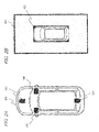
Fig. 4A shows aregion 719 where a part of the birds-eye-view image of the rearside imaging device 503 is displayed and aregion 720 where a part of the birds-eye-view image of the leftside imaging device 505 is displayed when a joint 718 is disposed in a radial direction from theend point 702 outside therange 705. -
Fig. 4B is a diagram illustrating a state in which two birds-eye-view images are combined based on the joint 718 andvertical subjects positions Fig. 3C . Thevertical subject 710 reflected at theposition 709, which falls down in only one direction of the direction of theradial line 711, in the same manner asFig. 3A , is displayed. - In contrast, the
vertical subject 714 reflected at theposition 713 is significantly different fromFig. 3C . Here, the display of falling-down in the direction of theradial line 716 depending on a positional relationship between theregion 719 and theregion 720 is disconnected at a position of theintersection 721 between the joint 718 and theradial line 716. In addition, the display of falling-down in the direction of theradial line 715 is disconnected at a position of theintersection 722 between the joint 718 and theradial line 715. Therefore, the subject 714 is discontinuously displayed. - At this time, the radial line intersects the joint 718 in the external direction (a direction directed to an opposite side to the rear side imaging device 503) from the
position 713 on theradial line 715 where thevertical subject 714 falls down. Similarly, the radial line also intersects the joint 718 in the external direction (a direction directed to an opposite side to the left side imaging device 505) from theposition 713 on theradial line 716 where thevertical subject 714 falls down. - As in the example of
Figs. 4A and 4B , when the joint 718 is disposed in a direction which is not a range between theradial line 703 and theradial line 704 extending from theend point 702 so as to be deviated from therange 705, both of the two radial lines may intersect the joint 718 in two external directions of the two radial lines from the two imaging devices depending on a position of a subject. For example, in external directions where falling-down occurs from the position of the subject 714 in the tworadial lines imaging devices radial lines vertical subject 714 is disconnected over the joint and is discontinuously displayed. - As described above, the birds-eye-view
image generation device 501 of the present embodiment includes the capturedimage acquisition unit 51 which acquires a captured image which is captured by a plurality ofimaging devices image conversion unit 52 which converts the acquired captured image into a birds-eye-view image through a viewpoint conversion process, the birds-eye-viewimage combining unit 53 which combines a plurality of converted birds-eye-view images, and thejoint setting unit 54. In two birds-eye-view images corresponding to twoimaging devices joint setting unit 54 sets any position of a rim of a vehicle image corresponding to the vehicle included in the birds-eye-view image as theend point 702 in the overlapping imaging range, and sets a line which extends in any direction on an opposite side to the vehicle image from theend point 702 between directions (radial directions) of the tworadial lines end point 702 from the twoimaging devices image combining unit 53. - In this case, in the external directions in which falling-down occurs of the two
radial lines 711 and 712 (715 and 716) passing through the position 709 (713) of the subject 710 (714) from the positions of the twoimaging devices radial lines 711 and 712 (715 and 716) intersects or either one intersects the joint 706. - Therefore, unlike in the state described in
Figs. 19C and 19D , a positional relationship between the vehicle itself and the birds-eye-view image, and a positional relationship on the reference height between the birds-eye-view images adjacent to each other can be maintained. Thus, in any birds-eye-view image of the imaging devices, a vertical subject which falls down in a radial direction from the imaging device is not reflected so as to be disconnected over a joint and be discontinuous. For this reason, a subject state or a position of a vehicle is easily recognized without misunderstanding. - In addition, as in an example of the combined birds-eye-view image shown in
Figs. 5A to 5D , any position of the rim of thevehicle image 602 may be set as an end point in an imaging range by two imaging devices regardless of thevehicle image 602 at an angle of view at which the imaging devices can perform imaging, and joints may be disposed within the respective ranges such asranges 801 to 804. - A configuration of the birds-eye-view image output system of the present embodiment is the same as the configuration of the birds-eye-view image output system of the first embodiment shown in
Fig. 1 , and thus description thereof will be omitted. -
Figs. 6A to 6C andFigs. 7A and 7B show an example of the combined portion of two birds-eye-view images adjacent to each other in the combined birds-eye-view image 603 (refer toFig. 2B ). In the same manner asFig. 3A ,Fig. 6A includes and shows thedisplay range 701 of the birds-eye-view image, theend point 702, theradial line 703, and theradial line 704. - In addition, in the drawings after
Figs. 6A to 6C , the same constituent element as that described previously is given the same reference numeral and detailed description thereof will be omitted. -
Fig. 6B shows adisplay region 902 where a part of the birds-eye-view image of the rearside imaging device 503 is displayed and adisplay region 903 where a part of the birds-eye-view image of the leftside imaging device 505 is displayed when a joint 901 is disposed so as to conform to a direction of theradial line 703 inFig. 6A , that is, is disposed along theradial line 703. -
Fig. 6C is a diagram illustrating a state in which two birds-eye-view images are combined based on the joint 901 ofFig. 6B andvertical subjects positions vertical subject 905 reflected at theposition 904 falls down in a direction of theradial line 906 passing through theposition 904 from the rearside imaging device 503 and in a direction of theradial line 907 passing through theposition 904 from the leftside imaging device 505. However, theimage display device 506 displays only the falling-down in the direction of theradial line 906 depending on the positional relationship between thedisplay region 902 and thedisplay region 903. - The joint 901 is disposed in the direction of the
radial line 703 from the position of the rearside imaging device 503. For this reason, thevertical subject 905, which is displayed so as to fall down in the direction of theradial line 906 passing through theposition 904 which is not present in the direction of theradial line 703 from the position of the rearside imaging device 503, does not intersect the joint 901. - In addition, the
vertical subject 909 reflected at theposition 908 falls down in a direction of theradial line 910 passing through theposition 908 from the rearside imaging device 503 and in a direction of theradial line 911 passing through theposition 908 from the leftside imaging device 505. However, theimage display device 506 displays only the falling-down in the direction of theradial line 910 depending on the positional relationship between theregion 902 and theregion 903. - The joint 901 is disposed in the direction of the
radial line 703 from the position of the rearside imaging device 503. For this reason, in the same manner as thevertical subject 905, thevertical subject 909, which is displayed so as to fall down in the direction of theradial line 910 passing through theposition 908 which is not present in the direction of theradial line 703 from the position of the rearside imaging device 503, does not intersect the joint 901. - As in the example of
Figs. 6A to 6C , in a case where the joint 901 is disposed so as to conform to the direction of theradial line 703 from the position of the rearside imaging device 503, the displayed falling-down does not occur in a direction crossing the joint 901 even if thevertical subjects display region 902 on which the birds-eye-view image of the rearside imaging device 503 is displayed. - On the other hand, when a joint does not conform to the direction of the
radial line 703 from the position of the rearside imaging device 503, falling-down of a vertical subject may occur in a direction crossing the joint even in the display region on which a part of the birds-eye-view image of the rearside imaging device 503 is displayed. InFigs. 3B and 3C described above, this does not occur due to the positional relationship between the joint 706 and thevertical subject 710, but this may occur depending on a positional relationship between a joint and a vertical subject. This will be supplementarily described with reference toFigs. 7A and 7B . -
Fig. 7A shows aregion 913 where a part of the birds-eye-view image of the rearside imaging device 503 is displayed and aregion 914 where a part of the birds-eye-view image of the leftside imaging device 505 is displayed when a joint 912 is disposed so as to conform to neither of theradial line 703 and theradial line 704, in theregion 705. -
Fig. 7B is a diagram illustrating a state in which two birds-eye-view images are combined based on the joint 912 ofFig. 7A andvertical subjects positions Fig. 6C . - The
vertical subject 905 reflected at theposition 904, which falls down in one direction of theradial line 906, in the same manner asFig. 6C , is displayed, but is disconnected at a position of theintersection 915 between the joint 912 and theradial line 906. At this time, thevertical subject 905 which is displayed so as to fall down in the direction of theradial line 906 from the position of the rearside imaging device 503 intersects the joint 912. - In addition, the
vertical subject 909 reflected at theposition 908 falls down in a direction of theradial line 910 passing through theposition 908 from the rearside imaging device 503 and in a direction of theradial line 911 passing through theposition 908 from the leftside imaging device 505. However, theimage display device 506 displays only the falling-down in the direction of theradial line 911 depending on the positional relationship between thedisplay region 913 and thedisplay region 914. At this time, thevertical subject 909 does not intersect the joint 912 but is not parallel with theradial line 911 and the joint 912 and thus intersects the joint out of thedisplay regions 913 and 914 (refer toFig. 7A ). - As in the example of
Figs. 7A and 7B , the extending direction of the joint 912 does not conform to the direction of theradial line 906 from the position of the rearside imaging device 503. The position of the rearside imaging device 503 is a base point of the falling-down direction of thevertical subject 905 of thedisplay region 913. For this reason, there are cases where falling-down crosses the joint 912 depending on a position of thevertical subject 905. In this case, thevertical subject 905 is disconnected and disappears in the middle within a range included in the birds-eye-view image. - As described above, in the birds-eye-view
image generation device 501 of the present embodiment, thejoint setting unit 54 sets the joint 901 along either one of directions (radial directions) of tworadial lines side imaging device 503 which is used as a reference of the direction of theradial line 703 to which the joint 901 conforms (follows), falling-down of the vertical subject does not occur in a direction crossing the joint 901 in any position. Thereby, the subject is largely displayed without being disconnected and disappearing in the middle in a range included in the birds-eye-view image of theinverse quantization unit 503. Therefore, the presence of the subject is easily recognized. - In addition, as in an example of the combined birds-eye-view image shown in
Figs. 8A to 8D , any position of the rim of thevehicle image 602 may be set as an end point in an imaging range by two imaging devices regardless of thevehicle image 602 at an angle of view at which the imaging devices can perform imaging, and joints may be disposed within the respective ranges such asranges 1101 to 1104. - A configuration of the birds-eye-view image output system of the present embodiment is the same as the configuration of the birds-eye-view image output system of the first embodiment shown in
Fig. 1 , and thus description thereof will be omitted. -
Figs. 9A and 9B andFig. 10A and 10B are diagrams illustrating an example of the combined birds-eye-view image 603.Fig. 9A shows a relationship between aradial line 1102 indicating a line of sight direction from a position of adriver 1101, and a radial dottedline 1103 indicating a falling-down direction when a vertical subject is reflected in a birds-eye-view image of the rearside imaging device 503. In addition,Fig. 9B shows a relationship between theradial line 1102 indicating a line of sight direction from the position of thedriver 1101, and a radial dottedline 1104 indicating a falling-down direction when a vertical subject is reflected in a birds-eye-view image of the leftside imaging device 505. - As shown in
Fig. 10A , anend point 1105 of a joint close to the imaging device is disposed. In a case where there is a vertical subject at apoint 1109 in arange 1108 surrounded by aradial line 1106 passing through the position of theend point 1105 from the position of the rearside imaging device 503, aradial line 1107 passing through the position of theend point 1105 from the position of the leftside imaging device 505, and a range included in the combined birds-eye-view image, a condition in which a joint is disposed in any radial direction from theend point 1105 will be examined. - In this case, as shown in
Fig. 10B , when a joint is disposed such that a birds-eye-view image of the leftside imaging device 505 is displayed at thepoint 1109, falling-down of the vertical subject in a direction 1111 (in a direction of theend point 1105 from the left side imaging device 505) close to the line ofsight direction 1110 of the driver is displayed. On the other hand, falling-down in a direction 1112 (in a direction of theend point 1105 from the rear side imaging device 503) distant from 1110 is not displayed. Around thepoint 1109, only a birds-eye-view image is displayed in which a falling-down direction of the subject is close to a line of sight direction in which the driver views the vertical subject from the driver's seat. - In addition, as can be understood from
Fig. 10B , the fact that the line of sight direction is close to the falling-down direction indicates that an angle formed by the line of sight direction and the falling-down direction is smaller, and the fact that the line of sight direction is distant from the falling-down direction indicates that an angle formed by the line of sight direction and the falling-down direction is larger. - As described above, in the birds-eye-view
image generation device 501 of the present embodiment, thejoint setting unit 54 sets a joint in a direction close to theradial line 1107 from the line ofsight direction 1110 when a first angle formed by the line ofsight direction 1110 of thedriver 1101 of the vehicle and the direction of the radial line 1107 (a first radial direction) is smaller than a second angle formed by the line ofsight direction 1110 and the direction of the radial line 1106 (a second radial direction) in two birds-eye-view images. - In this case, the birds-eye-view image side in which the falling-down direction of the vertical subject is close to the line of sight direction of the driver is displayed, and the birds-eye-view image side in which the falling-down direction of the vertical subject is distant from the line of sight direction of the driver is not displayed. Thereby, only the birds-eye-view image is displayed in which the falling-down direction of the subject is close to the line of
sight direction 1110 in which thedriver 1101 views the vertical subject from the driver's seat. Therefore, a direction in which a subject is present with respect to a driver is easily recognized. - A configuration of the birds-eye-view image output system of the present embodiment is the same as the configuration of the birds-eye-view image output system of the first embodiment shown in
Fig. 1 , and thus description thereof will be omitted. -
Figs. 11A to 11C are diagrams illustrating an example of a part of the combined birds-eye-view image 603 (refer toFig. 2B ).Fig. 11A shows thatend points 1201 of joints close to the imaging devices are respectively located on sides indicating the left end and the right end of thevehicle image 602, andjoints 1202 extend from therespective end points 1201. In addition, the left end and the right end here do not include corner portions. - Here, it is assumed that the height direction of the rear
side imaging device 503 is a relatively short distance with respect to the vehicle, that is, the height thereof is substantially the same as the height of the vehicle. In addition, it is assumed that the rearside imaging device 503 is located as at a rear end side as possible among the left, right and center of the vehicle. Further, it is assumed that the rear side imaging device is mounted on a typical layout arrangement such that the vehicle and the ground are reflected (the vehicle and the ground are included in the imaging range of the rear side imaging device 503). - In a case where a vehicle with a height from the reference height is projected in a birds-eye-view image of the rear
side imaging device 503, and thereby the vehicle is viewed vertically downward from the top (a virtual viewpoint of the birds-eye-view image), a vehicle rear direction of which a distance to a vehicle reflected in the rearside imaging device 503 is short has no deviation in most cases. On the other hand, a vehicle crosswise direction of which a distance to a vehicle reflected in the rearside imaging device 503 is long is considerably deviated, and thus the vehicle is reflected in aregion 1203. - When the vehicle is deviated and is reflected in the
region 1203, as can be seen fromFig. 11A , there is a location where continuity of a subject on the reference height between the rearside imaging device 503 and the leftside imaging device 505 or the rearside imaging device 503 and the rightside imaging device 504 is lost over the joint 1202. In addition, a reflection of the vehicle including the side indicating the vehicle rear end is adjacent to the side indicating the side end of thevehicle image 602, and thereby a directionality (that is, in which direction the subject is present when viewed from the vehicle) of the subject with respect to the vehicle is also lost. - In addition,
Fig. 11B shows thatrespective end points 1204 of joints close to the imaging devices are located on the side indicating the rear end of thevehicle image 602, andjoints 1205 extend from therespective end points 1204. - Here, it is assumed that the height direction of the left
side imaging device 505 and the rightside imaging device 504 is a relatively short distance with respect to the vehicle, that is, the height of the leftside imaging device 505 or the rightside imaging device 504 is substantially the same as the height of the vehicle. In addition, it is assumed that the leftside imaging device 505 and the rightside imaging device 504 are located as at a left end side or a right end side of the vehicle as possible. Further, it is assumed that the left side imaging device or the right side imaging device is mounted on a typical layout arrangement such that the vehicle and the ground are reflected (the vehicle and the ground are included in the imaging range of the leftside imaging device 505 or the right side imaging device 504). - In this case, when a vehicle with a height from the reference height is projected in a birds-eye-view image of the left
side imaging device 505 or the rightside imaging device 504, and thereby the vehicle is viewed vertically downward from the top, a position thereof may be deviated in the birds-eye-view image. Here, when the vehicle top (a virtual viewpoint of a birds-eye-view image) is used as a reference, a vehicle crosswise direction of which a distance to a vehicle reflected in the leftside imaging device 505 or the rightside imaging device 504 is short has no deviation in most cases. On the other hand, a vehicle front-back direction of which a distance to a vehicle reflected in the leftside imaging device 505 or the rightside imaging device 504 is long is considerably deviated, and thus the vehicle is reflected in aregion 1206 or aregion 1207. - When the vehicle is deviated and reflected in the
region 1206 or theregion 1207, as can be seen fromFig. 11B , there is a location where continuity of a subject on the reference height between the rearside imaging device 503 and the leftside imaging device 505 or the rearside imaging device 503 and the rightside imaging device 504 is lost over the joint 1205. In addition, a reflection of the vehicle including the side indicating the vehicle rear end is adjacent to the side indicating the rear end of thevehicle image 602, and thereby a directionality (that is, in which direction the subject is present when viewed from the vehicle) of the subject for the vehicle is also lost. - Meanwhile,
Fig. 11C shows that anend point 1208 of a joint 1209 for combining birds-eye-view images of the rearside imaging device 503 and the leftside imaging device 505 is disposed so as to be located at a corner of the sides of thevehicle image 602. - In
Fig. 11C , the vehicle on a birds-eye-view image generated from a captured image of the rearside imaging device 503, reflected in theregion 1203 so as to be considerably deviated inFig. 11A , and the vehicle on a birds-eye-view image generated from a captured image of the leftside imaging device 505 or the rightside imaging device 504, reflected in theregion 1206 so as to be considerably deviated inFig. 11B , are not displayed. - As in the example of
Figs. 11A and 11B , if the end point of the joint close to the imaging device is disposed so as to be deviated from the corner of the sides of thevehicle image 602, the display regions of two birds-eye-view images are adjacent to the side indicating one rear end or side end of thevehicle image 602, and thus there is a probability that a vehicle which is reflected so as to be considerably deviated from a practical position may be displayed when viewed vertically downward from the vehicle top. On the other hand, as in the example ofFig. 11C , if the end point is disposed at the corner of the sides of thevehicle image 602, the display region of a single birds-eye-view image is adjacent to the side indicating one rear end or side end of thevehicle image 602, and it is difficult for a vehicle which is reflected so as to be considerably deviated, to be displayed. - In addition, the rear end of the vehicle here corresponds to the rear end (lower end) of the
vehicle image 602 inFigs. 11A to 11C . Further, the side end of the vehicle here corresponds to the side end (the left end or the right end) of thevehicle image 602 inFigs. 11A to 11C . - Further, as shown in
Fig. 12 , a joint 1301 is disposed using acorner 1302 of the sides of thevehicle image 602 as an end point of the joint 1301 close to the imaging device. A joint 1303 is disposed using acorner 1304 of the sides of thevehicle image 602 as an end point of the joint 1303 close to the imaging device. A joint 1305 is disposed using acorner 1306 of the sides of thevehicle image 602 as an end point of the joint 1305 close to the imaging device. A joint 1307 is disposed using acorner 1308 of the sides of thevehicle image 602 as an end point of the joint 1307 close to the imaging device. - In this case, one entire side indicating a part of the rim of the
display region 1310 on which a part of the birds-eye-view image of the frontside imaging device 502 is displayed is adjacent to theentire side 1309 indicating the front end of thevehicle image 602. One entire side indicating a part of the rim of thedisplay region 1312 on which a part of the birds-eye-view image of the leftside imaging device 505 is displayed is adjacent to theentire side 1311 indicating the left end of thevehicle image 602. One entire side indicating a part of the rim of thedisplay region 1314 on which a part of the birds-eye-view image of the rearside imaging device 503 is displayed is adjacent to theentire side 1313 indicating the rear end of thevehicle image 602. One entire side indicating a part of the rim of thedisplay region 1316 on which a part of the birds-eye-view image of the rightside imaging device 504 is displayed is adjacent to theentire side 1315 indicating the right end of thevehicle image 602. - As in the example of
Fig. 12 , if the end points of the joints close to the imaging devices are disposed at all the corners (each corner at which the sides of the display regions on which a portion of two birds-eye-view images adjacent to each other in a combined arrangement is displayed intersect each other) of the sides of thevehicle image 602, and the combined birds-eye-view image 603 is generated, the display region on which a part of a single birds-eye-view image is displayed is adjacent to one side of thevehicle image 602. For this reason, each side of thevehicle image 602 conforms to the directionality of each birds-eye-view image for the vehicle. - In addition, the joint of the combined birds-eye-
view image 603 displayed by theimage display device 506 has a predetermined width, and this enables the driver to view and clearly recognize the gap of the birds-eye-view images. - As described above, in the birds-eye-view
image generation device 501 of the present embodiment, thejoint setting unit 54 sets the corner portion of thevehicle image 602 as an end point in two birds-eye-view images. In this case, since a corner at which two sides close to the imaging device intersect each other is set as an end point of the joint in the display regions of which a portion of the two birds-eye-views images are displayed, only a single display region of a birds-eye-view image generated from the imaging device of which a position is closest to one side of thevehicle image 602 is adjacent to the one side of thevehicle image 602 in the combined birds-eye-view image 603 of the vehicle periphery. - Thereby, in a range of the display region on which a part of the birds-eye-view image is displayed, it is difficult for a vehicle with a height from the reference height to be displayed, and an unnecessary reflection of the vehicle itself is easily removed. In addition, one side of the
vehicle image 602 conforms to a direction of the birds-eye-view image, and thus a direction in which a subject is present with respect to the vehicle is easily recognized. -
Fig. 13 is a block diagram illustrating a configuration example of the birds-eye-view image output system according to a fifth embodiment of the present invention. - The birds-eye-view
image generation device 1401 is mounted on, for example, a vehicle, and performs various processes such as a process of generating a birds-eye-view image. A steering-wheel steeringangle detection device 1402 detects a straight traveling state, a turn-left state, a turn-right state, or a rotation angle of a steering wheel of the vehicle, so as to be output to the birds-eye-viewimage generation device 1401. A travelingstate detection device 1403 detects information such as whether or not the vehicle is driven in a forward state or a backward state so as to be output to the birds-eye-viewimage generation device 1401. A driver'soperation reception device 1404 receives information which is input by a driver through an input device (not shown) installed in the vehicle, and output the information to the birds-eye-viewimage generation device 1401. Anobstacle detection device 1405 detects an obstacle from a captured image or the like acquired by a sonar or an imaging device mounted on the vehicle, and output information thereof to the birds-eye-viewimage generation device 1401. These devices are electrically connected to each other. - As shown in
Fig. 13 , the birds-eye-viewimage generation device 1401 is connected to the frontside imaging device 502, the rearside imaging device 503, the rightside imaging device 504, the leftside imaging device 505, the steering-wheel steeringangle detection device 1402, the travelingstate detection device 1403, the driver'soperation reception device 1404, and theobstacle detection device 1405 on the input side, and is connected to theimage display device 506 on the output side. - In addition, the birds-eye-view
image generation device 1401 includes a vehicleinformation acquisition unit 56 which acquires vehicle information of the vehicle in which the birds-eye-viewimage generation device 1401 is mounted, in addition to the configuration portion realizing the function of the birds-eye-viewimage generation device 501 as shown inFig. 1 . The vehicleinformation acquisition unit 56 acquires a variety of vehicle information from the steering-wheel steeringangle detection device 1402, the travelingstate detection device 1403, the driver'soperation reception device 1404, and theobstacle detection device 1405, via a line or a cable in a wired or wireless manner. - Next,
Figs. 14A and 14B ,Figs. 15A and 15B ,Figs. 16A and 16B , andFig. 17 are diagrams illustrating an example of the combined birds-eye-view image 603 (refer toFig. 6B ).Fig. 14A showsranges 1501 to 1504 in which respective joints may be located in a case where the joints are disposed in any radial directions by using respective corners of thevehicle image 602 as end points of the joints close to the imaging devices. - The birds-eye-view ima-
ge generation device 1401 can acquire a variety of vehicle information as described above in real time during a driving operation, by using the steering-wheel steeringangle detection device 1402, the travelingstate detection device 1403, the driver'soperation reception device 1404, and theobstacle detection device 1405. Thereby, thejoint setting unit 54 can switch joints to optimal positions in theranges 1501 to 1504 depending on usages or peripheral circumstances of the vehicle. -
Fig. 14B shows a case where joints are disposed at boundary positions (one of sides which are rims of the range 1501) in theranges 1501 to 1504. Two joints are present for each corner of thevehicle image 602. - Here, it is assumed that a vertical subject is reflected at a position of the reference height of each region, in a
region 1506 for a joint 1505, in aregion 1508 for a joint 1507, in aregion 1510 for a joint 1509, in aregion 1512 for a joint 1511, in aregion 1514 for a joint 1513, in aregion 1516 for a joint 1515, in aregion 1518 for a joint 1517, and in aregion 1520 for a joint 1519. - In this case, since falling-down of a subject occurs in a direction crossing the joint in the display region of the birds-eye-view image, there is a probability that the display in the height direction of the subject may be disconnected and disappear due to influence thereof.
- Based on this, when the vehicle moves backward, since the background flows in a direction (upward in the figure) of the
arrows 1521 on the combined birds-eye-view image 603 as shown inFig. 15A , the driver desires to visually recognize theregions 1522 sides most, and thus it is prioritized to enable a vertical subject not to be disconnected and disappear inside the display regions of the birds-eye-view images in theregions 1522. In this case, as shown inFig. 15B , preferably, the regions which are disposed at thejoints joints regions 1522. - In addition, when the vehicle moves forward, since the background flows in a direction (downward in the figure) of the
arrows 1523 on the combined birds-eye-view image 603 as shown inFig. 16A , the driver desires to visually recognize theregions 1524 sides most, and thus it is prioritized to enable a vertical subject not to be disconnected and disappear inside the display regions of the birds-eye-view images in theregions 1524. - In this case, as shown in
Fig. 16B , preferably, the regions which are disposed at thejoints joints regions 1524. - In addition, in a case of changing (including setting) a position of the joint, as in
Fig. 17 ,joints 1531 to 1534 may not be horizontally symmetrical. - As described above, the birds-eye-view
image generation device 501 of the present embodiment includes the vehicleinformation acquisition unit 56 which acquires vehicle information of the vehicle in which the birds-eye-viewimage generation device 501 is mounted. Thejoint setting unit 54 sets a joint on the basis of the acquired vehicle information. In this case, a joint is changed between two radial directions directed to the end point from the positions of the imaging devices depending on vehicle information. For example, a joint is set so as to avoid a region on a traveling direction side (for example, a rear side when moving backward) of the vehicle, and regions in an opposite direction (for example, a front left and right sides when moving backward) to the traveling direction in a direction perpendicular to the traveling direction. Thereby, joints can be switched to optimal states depending on usages or peripheral circumstances of the vehicle. Therefore, a subject state or a position of the vehicle is easily recognized without misunderstanding. - A configuration of the birds-eye-view image output system of the present embodiment is the same as the configuration of the birds-eye-view image output system of the first embodiment shown in
Fig. 1 , and thus description thereof will be omitted. -
Fig. 18 is a diagram illustrating an example of the output image of the birds-eye-viewimage generation device 1401. As anoutput image 1601 shown inFig. 18 , the combined birds-eye-view image 603 and a viewpoint-converted image different from the combined birds-eye-view image 603 are simultaneously output. The viewpoint-converted image may be at least a part of a birds-eye-view image, may be at least a part of a captured image acquired by the imaging device, or may be images other than this. InFig. 18 , in theoutput image 1601, the combined birds-eye-view image 603 is disposed on the right part, and the viewpoint-converted image of the left part of the vehicle in which thevehicle 1602 is reflected is disposed on the left part. - The
output image 1601 is output to theimage display device 506 by theimage output unit 55 included in the birds-eye-viewimage generation device 1401. Theimage display device 506 simultaneously displays a plurality of images included in the output image. - In addition, the disposition of each image in the
output image 1601 may be changed in consideration of usages of the image which is output at the same time as the combined birds-eye-view image, a directionality of the output image for the vehicle (which part is indicated by the image), and the like. - As described above, the birds-eye-view
image generation device 501 of the present embodiment includes theimage output unit 55 which simultaneously outputs a combined birds-eye-view image (a first image) combined by the birds-eye-viewimage combining unit 53 and a captured image acquired by the capturedimage acquisition unit 51 or a birds-eye-view image (a second image) converted by theimage conversion unit 52. In other words, the combined birds-eye-view image, and the second image which has a viewpoint different from the combined birds-eye-view image or displays a portion which is not displayed in the combined birds-eye-view image, may be simultaneously output. - Thereby, it is possible to improve visibility of a solid body which is considerably deformed and is thus hard for a driver to recognize on a combined birds-eye-view image in an image displayed on the
image display device 506. In addition, it is possible to obtain a wide field of view in a case of display a portion which is not displayed in the combined birds-eye-view image. As above, the visibility is supplemented by the second image. - While the present invention has been described in detail, or with reference to the specific embodiments, it is apparent for those skilled in the art that the invention may be modified and changed in various manners without departing from the scope and spirit of the invention.
- The present application is based on Japanese Patent Application No.
2011-217954 filed on September 30, 2011 - The present invention is suitable for a birds-eye-view image generation device, a birds-eye-view image generation method, a birds-eye-view image generation program, and the like, capable of recognizing a position or a shape of a subject with high accuracy in a combined birds-eye-view image.
-
- 101 First reference height
- 102 Second reference height
- 103, 104, and 105 Subject
- 201 Imaging device
- 202 Ground
- 203 Cuboid
- 301 Imaging device
- 302 and 305 Cuboid
- 303 and 306 Grid line
- 304 Birds-eye-view image
- 307 Position
- 401 and 402 Imaging device
- 403, 404, 405, 406, and 407 Region
- 408, 409 and 410 Dotted line
- 411 Point
- 412 Cuboid
- 501 Birds-eye-view image generation device
- 502 Front side imaging device
- 503 Rear side imaging device
- 504 Right side imaging device
- 505 Left side imaging device
- 506 Image display device
- 51 Captured image acquisition unit
- 52 Image conversion unit
- 53 Birds-eye-view image combining unit
- 54 Joint setting unit
- 55 Image output unit
- 56 Vehicle information acquisition unit
- 601 Vehicle
- 602 Vehicle image
- 603 Combined birds-eye-view image
- 701 Display range of birds-eye-view image
- 702 End point
- 703 and 704 Radial line passing through end point from position of imaging device
- 705 Range surrounded by
display range 701,radial line 703, andradial line 704 - 706 and 718 Joint
- 707, 708, 719 and 720 Region
- 709 and 713 Position
- 710 and 714 Subject
- 711, 712, 715 and 716 Radial direction
- 717, 721 and 722 Intersection
- 801, 802, 803 and 804 Range
- 901 and 912 Joint
- 902, 903, 913 and 914 Display region of birds-eye-view image
- 904 and 908 Position on reference height
- 905 and 909 Subject
- 906, 907, 910 and 911 Radial direction
- 915 Intersection
- 1001, 1002, 1003 and 1004 Radial direction
- 1101 Position of driver
- 1102 Radial line indicating line of sight direction
- 1103 and 1104 Radial dotted line indicating falling-down direction
- 1105 End point
- 1106 and 1107 Radial line
- 1108 Range
- 1109 Point
- 1110 Line of sight direction
- 1111 Direction close to line of sight direction
- 1112 Direction distant from line of sight direction
- 1201, 1204, and 1208 End point
- 1202, 1205, and 1209 Joint
- 1203, 1206, and 1207 Region
- 1301, 1303, 1305, and 1307 Joint
- 1302, 1304, 1306, and 1308 Corner
- 1309, 1311, 1313, and 1315 Side
- 1310, 1312, 1314, and 1316 Display region of birds-eye-view image
- 1401 Birds-eye-view image generation device
- 1402 Steering-wheel steering angle detection device
- 1403 Traveling state detection device
- 1404 Driver's operation reception device
- 1405 Obstacle detection device
- 1501, 1502, 1503, and 1504 Range in which joint may be located
- 1505, 1507, 1509, 1511, 1513, 1515, 1517, and 1519 Joint
- 1506, 1508, 1510, 1512, 1514, 1516, 1518, and 1520 Region
- 1521 and 1523 Arrow
- 1522 and 1524 Region
- 1531, 1532, 1533, and 1534 Joint
- 1601 Output image
- 1602 Vehicle
Claims (9)
- A birds-eye-view image generation device comprising:a captured image acquisition unit configured to acquire captured images which are respectively captured by a plurality of imaging devices mounted on a vehicle;an image conversion unit configured to convert the captured images acquired by the captured image acquisition unit into birds-eye-view images through a viewpoint conversion process;a birds-eye-view image combining unit configured to combine the plurality of birds-eye-view images converted by the image conversion unit; anda joint setting unit configured to set any position of a rim of a vehicle image corresponding to a vehicle included in the birds-eye-view images as an end point in an overlapping imaging range in two birds-eye-view images corresponding to two imaging devices of which imaging ranges overlap each other, and configured to set a line which extends in any direction on an opposite side to the vehicle image from the end point and between two radial directions directed to the end point from the two imaging devices, as a joint which joins two birds-eye-view images which are combined by the birds-eye-view image combining unit.
- The birds-eye-view image generation device according to claim 1,
wherein the joint setting unit is configured to set the joint in either one of the two radial directions in the two birds-eye-view images. - The birds-eye-view image generation device according to claim 2,
wherein the joint setting unit is configured to set the joint in a direction close to a first radial direction from a line of sight direction when a first angle formed by the line of sight direction of a driver of the vehicle and the first radial direction is smaller than a second angle formed by the line of sight direction and a second radial direction. - The birds-eye-view image generation device according to any one of claims 1 to 3,
wherein the joint setting unit is configured to set a corner portion of the vehicle image as the end point in the two birds-eye-view images. - The birds-eye-view image generation device according to any one of claims 1 to 4, further comprising:a vehicle information acquisition unit configured to acquire vehicle information of the vehicle,wherein the joint setting unit is configured to set the joint on the basis of the vehicle information acquired by the vehicle information acquisition unit.
- The birds-eye-view image generation device according to claim 5,
wherein the vehicle information acquisition unit is configured to acquire the vehicle information including a traveling direction of the vehicle, and
wherein the joint setting unit is configured to set the joint so as to avoid a region on a traveling direction side of the vehicle, and regions in an opposite direction to the traveling direction in a direction perpendicular to the traveling direction. - The birds-eye-view image generation device according to any one of claims 1 to 6, further comprising:an image output unit configured to simultaneously output a combined birds-eye-view image which is combined by the birds-eye-view image combining unit and the captured image which is acquired by the captured image acquisition unit or the birds-eye-view image which is converted by the image conversion unit.
- A birds-eye-view image generation method of a birds-eye-view image generation device, comprising:acquiring captured images which are captured by a plurality of imaging devices;converting the acquired captured images into birds-eye-view images through a viewpoint conversion process;combining the plurality of converted birds-eye-view images; andsetting any position of a rim of a vehicle image corresponding to a vehicle included in the birds-eye-view image as an end point in an overlapping imaging range in two birds-eye-view images corresponding to two imaging devices of which imaging ranges overlap each other, and setting a line which extends in any direction on an opposite side to the vehicle image from the end point between two radial directions directed to the end point from the two imaging devices, as a joint which joins two birds-eye-view images which are combined by the birds-eye-view image combining unit.
- A birds-eye-view image generation program for causing a computer to execute each step of the birds-eye-view image generation method according to claim 8.
Applications Claiming Priority (2)
| Application Number | Priority Date | Filing Date | Title |
|---|---|---|---|
| JP2011217954 | 2011-09-30 | ||
| PCT/JP2012/005923 WO2013046593A1 (en) | 2011-09-30 | 2012-09-14 | Birds-eye-view image generation device, birds-eye-view image generation method, and birds-eye-view image generation program |
Publications (2)
| Publication Number | Publication Date |
|---|---|
| EP2763406A1 true EP2763406A1 (en) | 2014-08-06 |
| EP2763406A4 EP2763406A4 (en) | 2015-06-17 |
Family
ID=47994679
Family Applications (1)
| Application Number | Title | Priority Date | Filing Date |
|---|---|---|---|
| EP12834713.5A Withdrawn EP2763406A4 (en) | 2011-09-30 | 2012-09-14 | Birds-eye-view image generation device, birds-eye-view image generation method, and birds-eye-view image generation program |
Country Status (5)
| Country | Link |
|---|---|
| US (1) | US9715631B2 (en) |
| EP (1) | EP2763406A4 (en) |
| JP (1) | JP5962927B2 (en) |
| CN (1) | CN103477634B (en) |
| WO (1) | WO2013046593A1 (en) |
Families Citing this family (16)
| Publication number | Priority date | Publication date | Assignee | Title |
|---|---|---|---|---|
| CN104469135B (en) * | 2013-09-18 | 2017-11-28 | 株式会社理光 | Image processing system |
| JP5971223B2 (en) * | 2013-10-16 | 2016-08-17 | 株式会社デンソー | Composite image generator |
| JP6375633B2 (en) * | 2014-02-12 | 2018-08-22 | 株式会社デンソー | Vehicle periphery image display device and vehicle periphery image display method |
| US10336462B2 (en) | 2015-03-12 | 2019-07-02 | Vu Systems, LLC | Vehicle navigation methods, systems and computer program products |
| US20160300372A1 (en) * | 2015-04-09 | 2016-10-13 | Bendix Commercial Vehicle Systems Llc | System and Method for Graphically Indicating an Object in an Image |
| CN104967826A (en) * | 2015-07-03 | 2015-10-07 | 上海弼智仿生高科技有限公司 | Fixed area monitoring system and method |
| GB2556797B (en) * | 2015-11-06 | 2018-10-24 | Mitsubishi Electric Corp | Image processing apparatus, image processing method, and image processing program |
| JP6477444B2 (en) * | 2015-11-25 | 2019-03-06 | 株式会社デンソー | Display control apparatus and display control program |
| JP6730606B2 (en) * | 2016-11-25 | 2020-07-29 | 株式会社Jvcケンウッド | Overhead video generation device, overhead video generation system, overhead video generation method and program |
| KR102551099B1 (en) | 2017-01-13 | 2023-07-05 | 엘지이노텍 주식회사 | Apparatus of providing an around view, method thereof and vehicle having the same |
| US10436485B2 (en) * | 2017-11-14 | 2019-10-08 | Haier Us Appliance Solutions, Inc. | Sealed system for a packaged terminal air conditioner unit |
| JP2019151304A (en) * | 2018-03-06 | 2019-09-12 | アイシン精機株式会社 | Periphery monitoring device |
| GB2586712B (en) * | 2018-03-28 | 2021-12-22 | Mitsubishi Electric Corp | Image processing device, image processing method, and image processing program |
| US10967792B1 (en) * | 2018-10-12 | 2021-04-06 | Roger Stafford | Apparatus for monitoring periphery of a vehicle and displaying a view of the periphery on a display device |
| CN111402132B (en) * | 2020-03-11 | 2024-02-02 | 黑芝麻智能科技(上海)有限公司 | Reversing auxiliary method and system, image processor and corresponding auxiliary driving system |
| JPWO2021186853A1 (en) * | 2020-03-19 | 2021-09-23 |
Family Cites Families (12)
| Publication number | Priority date | Publication date | Assignee | Title |
|---|---|---|---|---|
| EP1150252B1 (en) | 2000-04-28 | 2018-08-15 | Panasonic Intellectual Property Management Co., Ltd. | Synthesis of image from a plurality of camera views |
| JP3300337B2 (en) * | 2000-04-28 | 2002-07-08 | 松下電器産業株式会社 | Image processing device and monitoring system |
| JP4256702B2 (en) | 2003-03-20 | 2009-04-22 | クラリオン株式会社 | Image display method, image display apparatus, and image processing apparatus |
| JP4639753B2 (en) * | 2004-10-25 | 2011-02-23 | 日産自動車株式会社 | Driving assistance device |
| JP4899367B2 (en) * | 2005-07-27 | 2012-03-21 | 日産自動車株式会社 | Overhead image display system and overhead image display method |
| JP4725233B2 (en) * | 2005-08-02 | 2011-07-13 | 日産自動車株式会社 | Overhead image display system |
| JP4254887B2 (en) * | 2006-07-06 | 2009-04-15 | 日産自動車株式会社 | Image display system for vehicles |
| US20090128630A1 (en) | 2006-07-06 | 2009-05-21 | Nissan Motor Co., Ltd. | Vehicle image display system and image display method |
| JP5182042B2 (en) * | 2008-11-28 | 2013-04-10 | 富士通株式会社 | Image processing apparatus, image processing method, and computer program |
| JP5068779B2 (en) * | 2009-02-27 | 2012-11-07 | 現代自動車株式会社 | Vehicle surroundings overhead image display apparatus and method |
| JP5503660B2 (en) * | 2009-09-24 | 2014-05-28 | パナソニック株式会社 | Driving support display device |
| JP5548002B2 (en) * | 2010-03-25 | 2014-07-16 | 富士通テン株式会社 | Image generation apparatus, image display system, and image generation method |
-
2012
- 2012-09-14 WO PCT/JP2012/005923 patent/WO2013046593A1/en active Application Filing
- 2012-09-14 CN CN201280016788.4A patent/CN103477634B/en active Active
- 2012-09-14 EP EP12834713.5A patent/EP2763406A4/en not_active Withdrawn
- 2012-09-14 JP JP2013535874A patent/JP5962927B2/en active Active
-
2013
- 2013-08-30 US US14/015,735 patent/US9715631B2/en active Active
Also Published As
| Publication number | Publication date |
|---|---|
| US20140002660A1 (en) | 2014-01-02 |
| CN103477634B (en) | 2016-11-23 |
| EP2763406A4 (en) | 2015-06-17 |
| JP5962927B2 (en) | 2016-08-03 |
| US9715631B2 (en) | 2017-07-25 |
| CN103477634A (en) | 2013-12-25 |
| JPWO2013046593A1 (en) | 2015-03-26 |
| WO2013046593A1 (en) | 2013-04-04 |
Similar Documents
| Publication | Publication Date | Title |
|---|---|---|
| EP2763406A1 (en) | Birds-eye-view image generation device, birds-eye-view image generation method, and birds-eye-view image generation program | |
| US9457719B2 (en) | Work vehicle periphery monitoring system and work vehicle | |
| JP4970379B2 (en) | Vehicle display device | |
| JP3894322B2 (en) | Vehicle visibility monitoring system | |
| JP5942979B2 (en) | Vehicle information display device and vehicle information display method | |
| US20190080496A1 (en) | Vehicle display device and display control method | |
| US20150187214A1 (en) | Drive assist device | |
| WO2019008764A1 (en) | Parking assistance method and parking assistance device | |
| US10919450B2 (en) | Image display device | |
| JP5451497B2 (en) | Driving support display device | |
| US20140012464A1 (en) | Vehicle periphery monitoring device | |
| US8848050B2 (en) | Drive assist display apparatus | |
| EP3967554B1 (en) | Vehicular display system | |
| JP3205730U (en) | Multi-screen switchable car side mirror | |
| JP5008611B2 (en) | Vehicle display device | |
| JP2006088722A (en) | Display device and method for vehicle | |
| JP2006343545A (en) | Camera system and vehicle-circumference monitoring apparatus | |
| WO2016088150A1 (en) | Vehicle-mounted display device, vehicle, and display method | |
| KR20170056100A (en) | Objects displaying apparatus of head up display and method thereof | |
| EP3888966B1 (en) | Vehicle display device | |
| JP6476644B2 (en) | Cognitive assist device | |
| EP3967553A1 (en) | Vehicular display system | |
| WO2019058595A1 (en) | Drive assist device, drive assist method, and program | |
| JP7184083B2 (en) | VEHICLE DISPLAY DEVICE, VEHICLE DISPLAY CONTROL METHOD, VEHICLE DISPLAY CONTROL PROGRAM | |
| JP2019038372A (en) | Image display device |
Legal Events
| Date | Code | Title | Description |
|---|---|---|---|
| PUAI | Public reference made under article 153(3) epc to a published international application that has entered the european phase |
Free format text: ORIGINAL CODE: 0009012 |
|
| 17P | Request for examination filed |
Effective date: 20130829 |
|
| AK | Designated contracting states |
Kind code of ref document: A1 Designated state(s): AL AT BE BG CH CY CZ DE DK EE ES FI FR GB GR HR HU IE IS IT LI LT LU LV MC MK MT NL NO PL PT RO RS SE SI SK SM TR |
|
| DAX | Request for extension of the european patent (deleted) | ||
| RAP1 | Party data changed (applicant data changed or rights of an application transferred) |
Owner name: PANASONIC INTELLECTUAL PROPERTY MANAGEMENT CO., LT |
|
| RAP1 | Party data changed (applicant data changed or rights of an application transferred) |
Owner name: PANASONIC INTELLECTUAL PROPERTY MANAGEMENT CO., LT |
|
| RA4 | Supplementary search report drawn up and despatched (corrected) |
Effective date: 20150518 |
|
| RIC1 | Information provided on ipc code assigned before grant |
Ipc: G06T 3/40 20060101ALI20150511BHEP Ipc: G06K 9/00 20060101AFI20150511BHEP Ipc: B60R 1/00 20060101ALI20150511BHEP Ipc: G06K 9/20 20060101ALI20150511BHEP |
|
| 17Q | First examination report despatched |
Effective date: 20181008 |
|
| STAA | Information on the status of an ep patent application or granted ep patent |
Free format text: STATUS: THE APPLICATION IS DEEMED TO BE WITHDRAWN |
|
| 18D | Application deemed to be withdrawn |
Effective date: 20190219 |