EP2763361B1 - Method and system for transmitting IP message, negotiating bandwidth saving capability and saving network bandwidth - Google Patents
Method and system for transmitting IP message, negotiating bandwidth saving capability and saving network bandwidth Download PDFInfo
- Publication number
- EP2763361B1 EP2763361B1 EP14166308.8A EP14166308A EP2763361B1 EP 2763361 B1 EP2763361 B1 EP 2763361B1 EP 14166308 A EP14166308 A EP 14166308A EP 2763361 B1 EP2763361 B1 EP 2763361B1
- Authority
- EP
- European Patent Office
- Prior art keywords
- message
- receiver
- bandwidth saving
- sender
- saving capability
- Prior art date
- Legal status (The legal status is an assumption and is not a legal conclusion. Google has not performed a legal analysis and makes no representation as to the accuracy of the status listed.)
- Active
Links
Images


Classifications
-
- H—ELECTRICITY
- H04—ELECTRIC COMMUNICATION TECHNIQUE
- H04L—TRANSMISSION OF DIGITAL INFORMATION, e.g. TELEGRAPHIC COMMUNICATION
- H04L47/00—Traffic control in data switching networks
- H04L47/10—Flow control; Congestion control
- H04L47/26—Flow control; Congestion control using explicit feedback to the source, e.g. choke packets
-
- H—ELECTRICITY
- H04—ELECTRIC COMMUNICATION TECHNIQUE
- H04L—TRANSMISSION OF DIGITAL INFORMATION, e.g. TELEGRAPHIC COMMUNICATION
- H04L47/00—Traffic control in data switching networks
- H04L47/10—Flow control; Congestion control
- H04L47/15—Flow control; Congestion control in relation to multipoint traffic
-
- H—ELECTRICITY
- H04—ELECTRIC COMMUNICATION TECHNIQUE
- H04L—TRANSMISSION OF DIGITAL INFORMATION, e.g. TELEGRAPHIC COMMUNICATION
- H04L47/00—Traffic control in data switching networks
- H04L47/10—Flow control; Congestion control
-
- H—ELECTRICITY
- H04—ELECTRIC COMMUNICATION TECHNIQUE
- H04L—TRANSMISSION OF DIGITAL INFORMATION, e.g. TELEGRAPHIC COMMUNICATION
- H04L47/00—Traffic control in data switching networks
- H04L47/10—Flow control; Congestion control
- H04L47/18—End to end
-
- H—ELECTRICITY
- H04—ELECTRIC COMMUNICATION TECHNIQUE
- H04L—TRANSMISSION OF DIGITAL INFORMATION, e.g. TELEGRAPHIC COMMUNICATION
- H04L47/00—Traffic control in data switching networks
- H04L47/10—Flow control; Congestion control
- H04L47/38—Flow control; Congestion control by adapting coding or compression rate
-
- H—ELECTRICITY
- H04—ELECTRIC COMMUNICATION TECHNIQUE
- H04L—TRANSMISSION OF DIGITAL INFORMATION, e.g. TELEGRAPHIC COMMUNICATION
- H04L47/00—Traffic control in data switching networks
- H04L47/70—Admission control; Resource allocation
-
- H—ELECTRICITY
- H04—ELECTRIC COMMUNICATION TECHNIQUE
- H04L—TRANSMISSION OF DIGITAL INFORMATION, e.g. TELEGRAPHIC COMMUNICATION
- H04L47/00—Traffic control in data switching networks
- H04L47/70—Admission control; Resource allocation
- H04L47/80—Actions related to the user profile or the type of traffic
- H04L47/801—Real time traffic
-
- H—ELECTRICITY
- H04—ELECTRIC COMMUNICATION TECHNIQUE
- H04L—TRANSMISSION OF DIGITAL INFORMATION, e.g. TELEGRAPHIC COMMUNICATION
- H04L47/00—Traffic control in data switching networks
- H04L47/70—Admission control; Resource allocation
- H04L47/82—Miscellaneous aspects
- H04L47/824—Applicable to portable or mobile terminals
-
- H—ELECTRICITY
- H04—ELECTRIC COMMUNICATION TECHNIQUE
- H04L—TRANSMISSION OF DIGITAL INFORMATION, e.g. TELEGRAPHIC COMMUNICATION
- H04L69/00—Network arrangements, protocols or services independent of the application payload and not provided for in the other groups of this subclass
- H04L69/04—Protocols for data compression, e.g. ROHC
-
- H—ELECTRICITY
- H04—ELECTRIC COMMUNICATION TECHNIQUE
- H04L—TRANSMISSION OF DIGITAL INFORMATION, e.g. TELEGRAPHIC COMMUNICATION
- H04L69/00—Network arrangements, protocols or services independent of the application payload and not provided for in the other groups of this subclass
- H04L69/16—Implementation or adaptation of Internet protocol [IP], of transmission control protocol [TCP] or of user datagram protocol [UDP]
- H04L69/161—Implementation details of TCP/IP or UDP/IP stack architecture; Specification of modified or new header fields
-
- H—ELECTRICITY
- H04—ELECTRIC COMMUNICATION TECHNIQUE
- H04L—TRANSMISSION OF DIGITAL INFORMATION, e.g. TELEGRAPHIC COMMUNICATION
- H04L69/00—Network arrangements, protocols or services independent of the application payload and not provided for in the other groups of this subclass
- H04L69/16—Implementation or adaptation of Internet protocol [IP], of transmission control protocol [TCP] or of user datagram protocol [UDP]
- H04L69/164—Adaptation or special uses of UDP protocol
-
- H—ELECTRICITY
- H04—ELECTRIC COMMUNICATION TECHNIQUE
- H04W—WIRELESS COMMUNICATION NETWORKS
- H04W28/00—Network traffic management; Network resource management
- H04W28/02—Traffic management, e.g. flow control or congestion control
- H04W28/06—Optimizing the usage of the radio link, e.g. header compression, information sizing, discarding information
-
- H—ELECTRICITY
- H04—ELECTRIC COMMUNICATION TECHNIQUE
- H04W—WIRELESS COMMUNICATION NETWORKS
- H04W28/00—Network traffic management; Network resource management
- H04W28/16—Central resource management; Negotiation of resources or communication parameters, e.g. negotiating bandwidth or QoS [Quality of Service]
- H04W28/18—Negotiating wireless communication parameters
-
- H—ELECTRICITY
- H04—ELECTRIC COMMUNICATION TECHNIQUE
- H04W—WIRELESS COMMUNICATION NETWORKS
- H04W80/00—Wireless network protocols or protocol adaptations to wireless operation
- H04W80/04—Network layer protocols, e.g. mobile IP [Internet Protocol]
Definitions
- the present invention relates to data transmission technologies in an Internet Protocol (IP) bearer network of a communication system, and more particularly, to methods and systems for transmitting an IP message, negotiating a bandwidth saving capability and saving network bandwidth.
- IP Internet Protocol
- FIG. 1 is a schematic diagram illustrating the structure of a conventional WCDMA network.
- the broken lines indicate signaling paths, and the solid lines indicate message transmission paths for bearing data.
- the data to be transmitted via an Nb interface between Media Gateways (MGWs) and the data to be transmitted via an Iu interface between a Universal Terrestrial Radio Access Network (UTRAN) and a Media Gate Way (MGW) can be borne by IP messages.
- User plane parameters can be negotiated by a User Plane (UP) Protocol on the Nb interface and Iu interface.
- UP User Plane
- a Mobile Service Control center server controls the MGW by the H.248 protocol via a Mc interface.
- the above-mentioned network structure may also be used in a fixed softswitch system, a CDMA system, an IP Multimedia Subsystem (IMS) of a fixed network or the like.
- IMS IP Multimedia Subsystem
- the protocol stack includes a data layer for transmitting data, a Real-Time Transport Protocol (RTP) layer, a User Datagram Protocol (UDP) layer, an IP layer and a link layer.
- the IP layer may be based on two versions including IP version 4 (IPv4) or IP version 6 (IPv6).
- the link layer is used for performing a cyclic redundancy check (CRC) on the IP message by an ETHER protocol and a Packet Over SDH/SONET (POS).
- CRC cyclic redundancy check
- POS Packet Over SDH/SONET
- the UDP layer is a simple data-oriented transmission protocol layer. On the UDP layer, data transmission channels are reserved respectively for different sessions according to port numbers. A sender sends UDP data via a source port of a data transmission channel, and a receiver receives data via a destination port of the data transmission channel.
- the UDP layer does not provide reliability, i.e., the sender sends the UDP data, but does not ensure that the UDP data can reach the receiver.
- the RTP layer is a protocol layer for providing end-to-end transmission services for data of real time characteristics, such as interactive voice data or image data.
- the RTP layer is defined to work in one-to-one or one-to-multiple transmission to provide time synchronization and data stream synchronization.
- the RTP layer usually transmits the data via the UDP layer, and one RTP data packet can be transmitted via two parts, one of which is based on RTP, and the other of which is based on Real-Time Transport Control Protocol (RTCP).
- RTCP Real-Time Transport Control Protocol
- the RTP layer is unable to provide a reliable transmission mechanism for the RTP data packets being transmitted in sequence and is unable to provide flow control and congestion control. These services are provided by the RTCP.
- Sequence numbers in the IP messages may be used by the receiver to reconstruct a sequence of the IP messages sent by the sender and can be used to determine the location of one IP message in the entire sequence of the IP messages sent by the sender. Timestamps in the IP messages may be used to calculate delay and jitter of the network transmission.
- FIG. 3 is a schematic diagram illustrating the structure of an RTP header of an IP message.
- the figure shows the format and contents of the RTP header, and usages of the fields in the RTP header are described as follows.
- the field of Version (V) is used to indicate version 2.
- the field of Padding (P) is configured as valid when the IP message has an additional padding byte.
- the field of extension (X) is used to indicate one extended header next to the RTP header (not being used at present).
- the field of a Contributor count (CC) is used to indicate the number of contributing source identifiers in the IP message with a maximum number of 15.
- the field of Marker (M), the meaning of which is specified by a session, is used for establishing borders between different data in the IP message.
- the field of a Payload type is used to indicate a service type of the data in the IP message.
- the field of Sequence Number is used to indicate a 16-bit sequence number of the IP message.
- the field of a timestamp is used to indicate a 16-bit sampling instant of the first byte of data in the IP message.
- the field of a Synchronization Source Identifier is used to indicate a synchronous source of the IP message.
- the field of a Contributing Source (CSRC) list is used to indicate all the contributor sources contained in the payload of the IP message and the number of which is given by the CC.
- FIG. 4 is a schematic diagram illustrating the structure of an IP message bearing the data compressed by an Adaptive Multi Rate (AMR) protocol. The structure is almost the same as that illustrated in Figure 2 except that an UP layer is added and the data is compressed by the AMR.
- AMR Adaptive Multi Rate
- UP data messages of the UP layer include control messages and data messages, and the control messages include Initialization messages, rate control messages, time alignment messages and error event messages.
- the UP data message of the UP layer includes a control part, a check part and a payload part.
- CRC checks are performed on both the UP headers of the compressed data and the compressed data if the type of the UP data message is the PDU Type 0, and the CRC checks are performed only on the UP header of the compressed data if the type of the UP data message is the PDU Type 1.
- the process for transmitting the IP message bearing data includes two parts: Part I a bandwidth saving capability of the IP message being negotiated; and Part II, the IP message being transmitted. Detailed descriptions of the two parts are given below.
- one party of a sender and a receiver of the IP message needs to determine the type of the IP message to be transmitted by the other party or the desired type of the IP message supported by the other party, so that a process for negotiating the bandwidth saving capability is needed. Since each bandwidth saving capability corresponds to one type of the IP message, after the bandwidth saving capability is negotiated, the type of the IP message to be transmitted can be determined by the two parties.
- a conventional process for negotiating the bandwidth saving capability is described as follows.
- An initiator of the IP message sends a bandwidth saving capability supported by the initiator to a receiver of the IP message; the receiver determines whether the bandwidth saving capability from the initiator is supported by the receiver; if the bandwidth saving capability is supported by the receiver, the receiver sends to the initiator a reply message of a successful negotiation, indicating a successful negotiation; otherwise, the receiver sends a reply message of an unsuccessful negotiation, indicating that the negotiation fails or another negotiation can be initiated.
- the process for negotiating the bandwidth saving capability of the IP message has following drawbacks, the sender of the IP message only sends one self-supported bandwidth saving capability to the receiver. Therefore, an unsuccessful negotiation or a re-negotiation occurs frequently, leading to a waste of resources in the communication system.
- two bandwidth saving capabilities of the IP message supported by the sender are indicated as 0 and 1, only the bandwidth saving capability indicated as 0 can be sent to the receiver, while the bandwidth saving capability supported by the receiver is indicated as 1. Therefore, an unsuccessful negotiation or a re-negotiation occurs.
- the IP message being transmitted.
- the type of the IP message used for transmitting data is determined according to the negotiated bandwidth saving capability, so that the data is transmitted via the IP message with the determined type.
- IP message At present, there are multiple types of the IP message, and two types commonly used currently are described below.
- Figure 3 shows the structure of a first type of the IP message which includes a compressed IP message header and compressed data, i.e., payload.
- the Internet Engineering Task Force IETF
- IETF Internet Engineering Task Force
- IETF provides multiple standards of IP message header compression for compressing an IP message header of a session, i.e., compressing an IP header, a UDP header and an RTP header.
- a lot of information in the IP message header does not change or changes a little; some information in the IP message header changes, but the difference between the information in two adjacent IP messages is invariable.
- the above-mentioned two types of information are referred to as stable information.
- a sender sends to a receiver the IP message which carries the IP message header having the stable information, and then the sender only sends to the receiver the IP message which carries the IP message header having variable information. If the stable information changes in the process of the session, the sender resends to the receiver the IP message which carries the IP message header having the changed stable information.
- the receiver rearranges the IP message header of each received IP message in the session according to the received stable information and the variable information.
- the data transmission by using the IP message with the above-mentioned type of the IP message has the following drawbacks.
- Second, the data transmission is suitable for only one session and can not be multiplied by multiple sessions.
- Figure 6 shows the structure of a second type of the IP message.
- a multiplex header technique and a RTP compression technique are used for the IP message with the second type of the IP message, i.e., a multiplex header is added to each IP sub-message, and a compression technique is used in the RTP layer.
- a multiplex header technique multiple IP sub-messages in multiple sessions which are identical in the source IP address and destination IP address are multiplied in one IP message, and the link layer, the IP layer and the UDP layer of each IP sub-message are unchanged in formats, and then the multiplied IP message is sent out.
- the destination port number in the UDP header is a fixed value, and the source port number in the UDP header is meaningless.
- Each IP sub-message includes a multiplex header which indicates the destination UDP port number and message length of the IP sub-message.
- the RTP compression technique used in the IP sub-message minimizes the RTP layer length by shortening or erasing some fields in the RTP layer.
- the length of some fields can be minimized, such as a timestamp and a sequence number; some fields are unnecessary in some communication system networking environment, such as a P, an M, a CC, an X, a CSRC field and the like are useless in the WCDMA system network and may be removed.
- the RTP header is compressed after the fields in the RTP header is erased or shortened.
- the receiver which receives the IP message can not determine the validity of each IP sub-message in the IP message, and thus there are problems in reliability and safety.
- a bidirectional connection is established between Terminal 1 with an IP address of 10.110.100.100 and a port number of 5000 and Terminal 2 with an IP address of 10.110.200.200 and a port number of 6000; and the two Terminals may transmit IP messages to each other.
- Terminal 1 is successfully subtracted, but Terminal 2 fails to be subtracted for some reasons and becomes a hanging terminal.
- IP address and the port number of Terminal 1 is assigned to a subsequent terminal; if the IP address and the port number are assigned to Terminal 3, and a bidirectional connection is established between Terminal 3 and Terminal 4 with an IP address of 10.110.200.200 and a port number of 5000; Terminal 3 and Terminal 4 transmit IP messages to each other.
- Terminal 3 receives the IP messages from two terminals, and the IP message from 10.110.200.200/5000 is legal, the IP message from 10.110.200.200/6000 is illegal and needs to be discarded. If the IP sub-message of the sent IP message does not include source information, the receiver is unable to determine the validity of the IP sub-message in the IP message; if no determination is made and all the IP sub-messages are taken as legal, the conversation quality will be affected, for example, a crosstalk may occur.
- the field for indicating the IP sub-message is so short that the length of the IP sub-message is indicated by at most one byte, and the indicated length is at most 255 bytes.
- the length of the IP sub-message can not be indicated, such as when video data is transmitted or an RTP redundant processing is given to the voice data, the payload length in the IP sub-message may be greater than 255 bytes, and in this way, the multiplex header technique can not be used.
- WO 02/15627 A1 discloses a method and a communication system comprising first network element connectable to a second network element.
- a network element is adapted to perform a mode selection procedure for selecting the same mode for bidirectional communication between the network elements.
- EP 1 248 431 A1 discloses a framework for achieving dynamic End-to-End Qos-negotiation and control coordination, with distributed multimedia applications.
- the framework builds upon dynamic capability negotiation and specification of Adaptation Paths and QoS Contracts, based on user preferences.
- SNDCP Network Dependent Convergence Protocol
- ROC 2508 Compressing IP/UDP/RTP Headers for Low-Speed Serial Links discloses a method for compressing the headers of IP/UDP/RTP datagrams to reduce overhead on low-speed serial links. In many cased, all three headers can be compressed to 2-4 bytes.
- SDP Session Description Protocol
- WO 02/15625 A1 discloses a method and system for providing a mode selection procedure. At least one of a first and second network elements are able to use one of two or more selectable modes for communicating with another network element. One or both of the network elements, or a third network element which is connectable with the first and second network elements, is adapted to perform a mode selection procedure for selecting the same mode for bidirectional communication between the network elements.
- the modes preferably are different codec types or channel-coding schemes, or radio interface protocol types.
- US 2001/0055317 A1 discloses a network relay apparatus and method of combining packets.
- Network load is reduced by combining packets by considering the MTU of a transmission path.
- a routing processing unit detects the transmission of a large number of packets addressed to the same destination network
- a routing information gathering unit determines the MTU of a transmission path along which the packets are to be transmitted.
- a combining unit assembles a combined packet by combining packets up to a length that does not exceed the MTU of the transmission path, and sends out the combined packet.
- the embodiments of the present invention provide a method and an apparatus for ensuring reliability of message transmission to ensure reliability and safety of transmitted messages.
- a method for ensuring reliability of message transmission includes:
- a sender apparatus includes:
- embodiments of the present invention provide a method for transmitting an IP message.
- network entities involved in the method include a sender and a receiver of an IP message.
- the method includes the following process.
- a sender sends to a receiver more than one bandwidth saving capability supported by the sender.
- the more than one bandwidth saving capability can be configured as a bandwidth saving capability set.
- the receiver selects one bandwidth saving capability from the more than one bandwidth saving capability according to a bandwidth saving capability supported by the receiver, and then the receiver sends to the sender the bandwidth saving capability selected from the more than one bandwidth saving capability.
- the receiver may configure a selecting policy of the bandwidth saving capability.
- the receiver may select the bandwidth saving capability which is supported by the receiver and saving maximum bandwidth (or other predetermined contents), and then the receiver sends the selected bandwidth saving capability to the sender.
- the sender determines a type of the IP message used for transmitting data, and the type of the IP message corresponds to the bandwidth saving capability selected by the receiver; and the sender sends to the receiver a message indicating that the bandwidth saving capability selected by the receiver is accepted.
- the sender constructs an IP message bearing data using the determined type and sends the IP message to the receiver.
- the IP message shown in Figure 6 may be used for transmitting data, but the following improvements are needed.
- a source ID indicating the information of the sender is carried in the multiplex header of the IP sub-message in the IP message.
- the source ID may be the User Datagram Protocol (UDP) port number of the session which the IP sub-message belongs to; or the source ID may be a value obtained by dividing the UDP port number by 2.
- UDP User Datagram Protocol
- the receiver may determine the validity according to the source ID indicating the information of the sender carried by the IP sub-message in the IP message.
- one byte in the multiplex header of the IP sub-message in the IP message is used to indicate the length of the IP sub-message, and the indicated length is less than 255 bytes.
- 2 bytes is used to indicate the length of the IP sub-message, instead of using 1 byte in the multiplex header in the prior art.
- this will waste network bandwidth of the communication system.
- another bit in the multiplex header is used to indicate the number of bytes in a field which indicates the length of the IP sub-message; for example, 0 indicates that 1 byte is used to indicate the length of the IP sub-message, and 1 indicates that 2 bytes are used to indicate the length of the IP sub-message, etc.
- the embodiment of the present invention provides a format of the UP data message with compressed data in the UP layer, only the UP header is compressed, and no CRC check is performed on the UP header and compressed data i.e., payload.
- the receiver resolves each IP sub-message in the IP message according to the type of IP message corresponding to the selected bandwidth saving capability and thus obtains the encapsulated data.
- the parameters are used for carrying multiple supported bandwidth saving capabilities; information indicating bandwidth saving capability may be in a variety of modes, and two modes are described below.
- IPFmts ⁇ 0,1 ⁇ indicates that the bandwidth saving capabilities as 0 or 1 are supported by an IP message with a payload type of 4.
- the method for negotiating the bandwidth saving capability of the IP message by the H.248 protocol and the SDP, using the IPBCP and the SDP, using the SIP and the SDP and using the UP are described below respectively.
- the IPBCP can not be used for negotiating the bandwidth saving capability between two media processing devices, and a media controlling device controls the media processing devices for negotiating by the H.248 protocol. During the negotiation, the media controlling device and media processing devices interact by the H.248.
- the LOCAL and REMOTE descriptors in the H.248 protocol may be used, and multiple bandwidth saving capabilities are described by the SDP. Here, multiple bandwidth saving capabilities are configured as bandwidth saving capability set. When there is no bandwidth saving capability in the SDP description, it is indicated that the bandwidth saving capability is not supported.
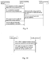
- FIG. 9 is a flowchart of a method for negotiating an IP message bandwidth saving capability by the H.248 protocol and the SDP in accordance with an embodiment of the present invention.
- Network entities involved in the method include a media processing device 1, a media controlling device and a media processing device 2; the media processing device 1 and media processing device 2 may respectively be an IP message sender and an IP message receiver.
- the method includes the following process.
- the media controlling device requests the media processing device 1 to provide a supported bandwidth saving capability set.
- the media processing device 1 sends to the media controlling device the supported bandwidth saving capability set.
- the media controlling device sends to the media processing device 2 the supported bandwidth saving capability set and requests the media processing device 2 to select a supported bandwidth saving capability.
- the media processing device 2 selects a supported bandwidth saving capability and returns the selected bandwidth saving capability to the media controlling device.
- the media controlling device requests the media processing device 1 to use the bandwidth saving capability selected by the media processing device 2.
- the media processing device 1 returns to the media controlling device a message indicating that the selected bandwidth saving capability is accepted.
- a receiver and a sender exchange negotiation parameters by the IPBCP, and the receiver and the sender may both be media gateways.
- the negotiation parameters may be a media stream characteristic, an IP address of a media stream carrier and a port number of a media stream carrier.
- the SDP is used by the IPBCP to describe a supported bandwidth saving capability set.
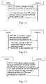
- FIG 10 is a flowchart of a method for negotiating a bandwidth saving capability of an IP message by the IPBCP and the SDP in accordance with an embodiment of the present invention.
- Network entities involved in the method include a media gateway 1 and a media gateway 2, and the method includes the following process.
- the media gateway 1 sends to the media gateway 2 an IPBCP request message carrying a bandwidth saving capability set supported by the media gateway 1, and the bandwidth saving capability set is described by the SDP.
- the media gateway 2 selects a bandwidth saving capability supported by the media gateway 2 from the received bandwidth saving capability set, and the media gateway 2 returns to the media gateway 1 a reply message carrying the selected bandwidth saving capability.
- the SDP description having the bandwidth saving capability set is removed in the reply message.
- the SDP is used by the SIP to describe the supported bandwidth saving capability set.
- Figure 11 is a flowchart of a method for negotiating a bandwidth saving capability of an IP message by the IPBCP and the SDP.
- Network entities involved in the method include a sender of the IP message and a receiver of the IP message. The method includes the following process.
- the sender sends to the receiver a SIP request message carrying the bandwidth saving capability set supported by the sender, and the bandwidth saving capability set is descript by the SDP.
- the receiver selects a bandwidth saving capability supported by the receiver from the bandwidth saving capability set and returns to the sender a reply message of the SIP request message carrying the selected bandwidth saving capability.
- the SDP description having the bandwidth saving capability set is removed in the reply message.
- an UP initialization message is used for negotiating user plane parameters between the UTRAN and the MGW and between the MGW and the MGW.
- an UP initialization request message and a reply message may be used for negotiating the bandwidth saving capability.
- Figure 12 is a flowchart of a method for negotiating a bandwidth saving capability of an IP message by the UP.
- Network entities involved in the method include a sender of the IP message and a receiver of the IP message. The method includes the following process.
- the sender sends to the receiver an UP initialization request message carrying a supported bandwidth saving capability set.
- the receiver selects a bandwidth saving capability supported by the receiver from the bandwidth saving capability set and returns to the sender a reply message of the UP initialization request message carrying the selected bandwidth saving capability.
- the UP may also be used for negotiating an UP header compression capability as shown in Figure 13 , and the negotiation includes the following process.
- a sender sends to a receiver an UP initialization request message carrying information indicating whether the UP header compression is supported by the sender.
- the receiver if the receiver supports the UP header compression and the received information from the sender indicating that the sender supports the UP header compression, the receiver sends to the sender a reply message of the UP initialization request message indicating that the UP header compression is supported; if any of the two parties does not support the UP header compression, the receiver returns to the sender the reply message of the UP initialization request message indicating that the UP header compression is not supported.
- two bitmaps (IPFmts) in an idle extended field in the UP initialization request message may be used for carrying the supported bandwidth saving capability set; one bit, BWS supported, in an idle extended field in the reply message may be used for indicating whether the receiver supports the bandwidth saving capability, and one bit, IPFMT, may be used for indicating the bandwidth saving capability selected by the receiver.
- one bit, UPC, in an idle extended field in the UP initialization request message may be used for indicating whether the sender supports the UP header compression;
- one bit, UPC, in an idle extended field in the reply message may be used for indicating whether the receiver supports the UP header compression.
- the sender assigns the IPFmts (bitmap) fields in the UP initialization request message according to the supported bandwidth saving capability set.
- the receiver selects one bandwidth saving capability supported by the receiver from the IPFmts (bitmap) fields in the received UP initialization request message, and then the receiver writes the supported bandwidth saving capability in the IP FMT field in the reply message of the UP initialization request message and sets the BWS supported field as 1 at the same time, thus the sender and the receiver may process the IP messages corresponding to the same bandwidth saving capability.
- the receiver If the receiver does not support the bandwidth saving capability, or not support the bandwidth saving capability in the IPFmts (bitmap) field in the received IP initialization request message, the receiver sets the BWS supported field as 0 in the reply message of the UP initialization request message, thus the sender and the receiver can only process ordinary IP messages.
- the sender may indicate in the UP initialization request message that whether the UP header compression is supported
- the receiver may indicate in the reply message of the UP initialization request message that whether the UP header compression is supported
- the UP header compression function can be used in the IP messages transmitted between the sender and the receiver.
- the UP header compression capability may also be described by the SDP, and the SDP may be used for negotiating the UP header compression capability.
- the SDP may be used for negotiating the UP header compression capability.
- IP message used in the embodiments of the present invention.
- the link layer, the IP layer and the UDP layer in the protocol stack bearing an IP message are all kept unchanged, multiple IP sub-messages are encapsulated in an IP message, each content of each session is carried in each IP sub-message, and there is a multiplex header in an IP sub-message as shown in Figure 6 .
- an RTP header is compressed. If the sender and the receiver both support the UP header compression, the UP header may also be compressed.
- the IP header format of the IP message is the same as that in the prior art;
- the UDP header is the same as that in the prior art, i.e., the destination UDP port number is a fixed value, the value of the source UDP port number is meaningless and may be any value;
- the multiplex header includes a multiplex ID, a source ID, a length indicator bit and a length field.
- the multiplex ID is the number of the destination UDP port receiving the sub-message or a value obtained by performing some operation of the number of the destination UDP port;
- the source ID is the number of the source UDP port sending the sub-message or a value obtained by performing some operation of the number of the source UDP port;
- the length indicator bit indicates the number of the bytes in the length field is 1 or 2 bytes; and the length field indicates the length of the IP sub-message.
- an UP header type is defined in the embodiment of the present invention, and the UP header with the UP header type does not include the CRC check of the UP header and the CRC check of the payload. As shown in Figure 14 , no CRC check is performed in the check part.
- IP message header of the IP message is compressed, the saved bandwidth is not obvious, so the IP message header is usually compressed after being multiplied.
- IP message formats Two examples are given below to define two IP message formats: one is that the IP message is only multiplied, the other is that IP message header of the IP message is compressed after being multiplied as shown in Figure 15 and 16 .
- a variety of IP message formats may be provided according to the multiplexing technique and a variety of IP message compression techniques.
- the IP message is only multiplied; the RTP header is not compressed and is kept unchanged.
- the MUXID may be expressed by the destination UDP port number divided by 2.
- the SourceID may be expressed by the source UDP port number or the source UDP port number divided by 2; and the receiver may use the SourceID to check the validity of the IP sub-message.
- the Length the length of the IP sub-message may be indicated by one byte or 2 bytes.
- the IP message is multiplied, and the RTP header is compressed.
- the contents of the multiplex header include an L, a MUXID, a SourceID, and a Length;
- the contents of the compressed RTP header include a P, an M, a Payload Type, a Time Stamp and a Sequence Number.
- the MUXID may be expressed by the destination UDP port number divided by 2.
- the SourceID may be expressed by the source UDP port number or the source UDP port number divided by 2, and the receiver may use the SourceID to check the validity of the IP sub-message.
- the Length the length of the IP sub-message may be indicated by one byte or 2 bytes.
- the usage of the P is consistent with that in the standard RTP header; if there is an additional padding byte in the IP sub-message, the flag is configured.
- the usage of the M is consistent with that in the standard RTP header; the meaning of the M is specified by the session, and the M is used for determining borders of different data.
- the usage of the Payload Type is consistent with that in the standard RTP header.
- the usage of the Sequence Number is consistent with that in the standard RTP header, and the length of the Sequence Number is 8 bits, which is 16 bits before being compressed.
- the usage of the Time Stamp is consistent with that in the standard RTP header, and the length of the Time Stamp is 16 bits, which is 32 bits before being compressed.
- the RTP header may be compressed by a structure as shown in Figure 6 .
- the IP message is multiplied, the RTP header is compressed and the data borne in the IP message is compressed. Therefore, the efficiency for processing the IP message by processing devices in the communication system is improved.
- a source indication is carried by the multiplex header of each IP sub-message in the IP message, thus the receiver may determine the validity of the IP message, the reliability and safety are improved.
- multiple bandwidth saving capabilities are carried at the same time, the success rate is improved.
- the H.248 protocol, the IPBCP and the SIP may be used, thus the negotiation methods can be applied in the case of Non-Tunnel in a circuit-switched core network of the WCDMA system and the fixed softswitch network.
- the embodiments of the present invention also provide a system for transmitting an IP message as shown in Figure 17 , and the system includes a sender and a receiver.
- the sender sends to the receiver more than one bandwidth saving capability supported by the sender, and determines a type of the IP message used for transmitting data according to a received bandwidth saving capability selected by the receiver, and then the sender sends an IP message to the receiver after constructing the IP message bearing data to be transmitted using the determined type of the IP message.
- the receiver selects the bandwidth saving capability from the more than one bandwidth saving capability sent by the sender according to a bandwidth saving capability supported by the receiver, and then the receiver sends the selected bandwidth saving capability to the sender.
- the sender and receiver also include RTP header compression capability negotiation modules respectively.
- the RTP header compression capability negotiation module of the sender sends to the receiver information indicating whether RTP header compression is supported by the sender and receives from the receiver information indicating whether the RTP header compression is supported, and the RTP header compression capability negotiation module of the sender compresses an RTP header when constructing the IP message if the RTP header compression is supported.
- the RTP header compression capability negotiation module of the receiver determines whether the RTP header compression is supported according to whether the RTP header compression is supported by the receiver and according to the received information indicating whether the RTP header compression is supported by the sender and sends to the sender the information indicating whether the RTP header compression is supported.
- the receiver further includes an IP message reception resolution module.
- the IP message reception resolution module resolves each IP sub-message in the IP message according to the type of IP message corresponding to the selected bandwidth saving capability and obtains the transmitted data.
- the embodiments of the present invention also provide a system for negotiating a bandwidth saving capacity.
- the system includes a sender and a receiver.
- the sender sends to the receiver more than one bandwidth saving capability supported by the sender and determines a type of the IP message used for transmitting data according to a received bandwidth saving capability selected by the receiver.
- the receiver selects the bandwidth saving capability from the more than one bandwidth saving capability sent by the sender according to a bandwidth saving capability supported by the receiver and sends the selected bandwidth saving capability to the sender.
- the sender further includes an IP message construction module to construct a multiplied IP message bearing the data to be transmitted according to the determined type of the IP message and to send to the receiver the multiplied IP message constructed.
- At least one IP sub-message having a multiplex header is included in the multiplied IP message.
- the multiplex header of the IP sub-message includes at least one of a source ID for indicating the information of the sender, an indication for indicating the number of bytes used for indicating the length of the IP sub-message and an indication for indicating the length of the IP sub-message.
- the sender further includes an IP message construction module to construct the IP message bearing the data to be transmitted after the IP message is compressed according to the determined type of the IP message.
- the IP message includes an UP data message without a CRC check and an UP header without a CRC check.
- the IP message construction module sends the constructed IP message to the receiver.
Landscapes
- Engineering & Computer Science (AREA)
- Computer Networks & Wireless Communication (AREA)
- Signal Processing (AREA)
- Computer Security & Cryptography (AREA)
- Data Exchanges In Wide-Area Networks (AREA)
- Telephonic Communication Services (AREA)
Description
- The present invention relates to data transmission technologies in an Internet Protocol (IP) bearer network of a communication system, and more particularly, to methods and systems for transmitting an IP message, negotiating a bandwidth saving capability and saving network bandwidth.
- In a communication system, such as an IP bearer network of a Wide Code Division Multiple Access (WCDMA) system, data is transmitted through being borne in a message, such as an IP message.
Figure 1 is a schematic diagram illustrating the structure of a conventional WCDMA network. In the figure, the broken lines indicate signaling paths, and the solid lines indicate message transmission paths for bearing data. The data to be transmitted via an Nb interface between Media Gateways (MGWs) and the data to be transmitted via an Iu interface between a Universal Terrestrial Radio Access Network (UTRAN) and a Media Gate Way (MGW) can be borne by IP messages. User plane parameters can be negotiated by a User Plane (UP) Protocol on the Nb interface and Iu interface. A Mobile Service Control center server (MSC server) controls the MGW by the H.248 protocol via a Mc interface. The above-mentioned network structure may also be used in a fixed softswitch system, a CDMA system, an IP Multimedia Subsystem (IMS) of a fixed network or the like. - For the purpose of bearing data in an IP message, a protocol stack bearing the IP message, as shown in
Figure 2 , is constructed. The protocol stack includes a data layer for transmitting data, a Real-Time Transport Protocol (RTP) layer, a User Datagram Protocol (UDP) layer, an IP layer and a link layer. The IP layer may be based on two versions including IP version 4 (IPv4) or IP version 6 (IPv6). The link layer is used for performing a cyclic redundancy check (CRC) on the IP message by an ETHER protocol and a Packet Over SDH/SONET (POS). Detailed descriptions for the RTP layer and the UDP layer are as follows. - The UDP layer is a simple data-oriented transmission protocol layer. On the UDP layer, data transmission channels are reserved respectively for different sessions according to port numbers. A sender sends UDP data via a source port of a data transmission channel, and a receiver receives data via a destination port of the data transmission channel. The UDP layer does not provide reliability, i.e., the sender sends the UDP data, but does not ensure that the UDP data can reach the receiver.
- The RTP layer is a protocol layer for providing end-to-end transmission services for data of real time characteristics, such as interactive voice data or image data. The RTP layer is defined to work in one-to-one or one-to-multiple transmission to provide time synchronization and data stream synchronization. The RTP layer usually transmits the data via the UDP layer, and one RTP data packet can be transmitted via two parts, one of which is based on RTP, and the other of which is based on Real-Time Transport Control Protocol (RTCP). The RTP layer is unable to provide a reliable transmission mechanism for the RTP data packets being transmitted in sequence and is unable to provide flow control and congestion control. These services are provided by the RTCP. Sequence numbers in the IP messages may be used by the receiver to reconstruct a sequence of the IP messages sent by the sender and can be used to determine the location of one IP message in the entire sequence of the IP messages sent by the sender. Timestamps in the IP messages may be used to calculate delay and jitter of the network transmission.
-
Figure 3 is a schematic diagram illustrating the structure of an RTP header of an IP message. The figure shows the format and contents of the RTP header, and usages of the fields in the RTP header are described as follows. The field of Version (V) is used to indicateversion 2. The field of Padding (P) is configured as valid when the IP message has an additional padding byte. The field of extension (X) is used to indicate one extended header next to the RTP header (not being used at present). The field of a Contributor count (CC) is used to indicate the number of contributing source identifiers in the IP message with a maximum number of 15. The field of Marker (M), the meaning of which is specified by a session, is used for establishing borders between different data in the IP message. The field of a Payload type (PT) is used to indicate a service type of the data in the IP message. The field of Sequence Number (SN) is used to indicate a 16-bit sequence number of the IP message. The field of a timestamp is used to indicate a 16-bit sampling instant of the first byte of data in the IP message. The field of a Synchronization Source Identifier (SSRC) is used to indicate a synchronous source of the IP message. The field of a Contributing Source (CSRC) list is used to indicate all the contributor sources contained in the payload of the IP message and the number of which is given by the CC. - The data borne in the IP message usually needs to be compressed. When the IP message bearing the compressed data is transmitted via the Iu interface and Nb interface, an UP header needs to be capsulated for the compressed data.
Figure 4 is a schematic diagram illustrating the structure of an IP message bearing the data compressed by an Adaptive Multi Rate (AMR) protocol. The structure is almost the same as that illustrated inFigure 2 except that an UP layer is added and the data is compressed by the AMR. - UP data messages of the UP layer include control messages and data messages, and the control messages include Initialization messages, rate control messages, time alignment messages and error event messages. There are two types of UP data message: a
PDU Type 0 and aPDU Type 1 as shown respectively inFigures 5a and 5b . - In
Figures 5a and 5b , the UP data message of the UP layer includes a control part, a check part and a payload part. As shown on the check part, CRC checks are performed on both the UP headers of the compressed data and the compressed data if the type of the UP data message is thePDU Type 0, and the CRC checks are performed only on the UP header of the compressed data if the type of the UP data message is thePDU Type 1. - The process for transmitting the IP message bearing data includes two parts: Part I a bandwidth saving capability of the IP message being negotiated; and Part II, the IP message being transmitted. Detailed descriptions of the two parts are given below.
- The bandwidth saving capability of the IP message being negotiated.
- Before the IP message is transmitted, one party of a sender and a receiver of the IP message needs to determine the type of the IP message to be transmitted by the other party or the desired type of the IP message supported by the other party, so that a process for negotiating the bandwidth saving capability is needed. Since each bandwidth saving capability corresponds to one type of the IP message, after the bandwidth saving capability is negotiated, the type of the IP message to be transmitted can be determined by the two parties. A conventional process for negotiating the bandwidth saving capability is described as follows. An initiator of the IP message sends a bandwidth saving capability supported by the initiator to a receiver of the IP message; the receiver determines whether the bandwidth saving capability from the initiator is supported by the receiver; if the bandwidth saving capability is supported by the receiver, the receiver sends to the initiator a reply message of a successful negotiation, indicating a successful negotiation; otherwise, the receiver sends a reply message of an unsuccessful negotiation, indicating that the negotiation fails or another negotiation can be initiated.
- However, the process for negotiating the bandwidth saving capability of the IP message has following drawbacks, the sender of the IP message only sends one self-supported bandwidth saving capability to the receiver. Therefore, an unsuccessful negotiation or a re-negotiation occurs frequently, leading to a waste of resources in the communication system. For example, two bandwidth saving capabilities of the IP message supported by the sender are indicated as 0 and 1, only the bandwidth saving capability indicated as 0 can be sent to the receiver, while the bandwidth saving capability supported by the receiver is indicated as 1. Therefore, an unsuccessful negotiation or a re-negotiation occurs. Further, in the process for negotiating the bandwidth saving capability of the IP message, there is no definition on how to use the H.248 protocol to negotiate the bandwidth saving capability of the IP message, such as how to negotiate the bandwidth saving capability of the IP message in the case of Non-Tunnel in a circuit-switched core network of a WCDMA system.
- The IP message being transmitted.
- When the negotiation for the bandwidth saving capability of the IP message is finished, the type of the IP message used for transmitting data is determined according to the negotiated bandwidth saving capability, so that the data is transmitted via the IP message with the determined type.
- At present, there are multiple types of the IP message, and two types commonly used currently are described below.
-
Figure 3 shows the structure of a first type of the IP message which includes a compressed IP message header and compressed data, i.e., payload. For the purpose of saving communication system resources taken by the IP message header, the Internet Engineering Task Force (IETF) provides multiple standards of IP message header compression for compressing an IP message header of a session, i.e., compressing an IP header, a UDP header and an RTP header. In the process of the session, a lot of information in the IP message header does not change or changes a little; some information in the IP message header changes, but the difference between the information in two adjacent IP messages is invariable. The above-mentioned two types of information are referred to as stable information. At the beginning of the session, a sender sends to a receiver the IP message which carries the IP message header having the stable information, and then the sender only sends to the receiver the IP message which carries the IP message header having variable information. If the stable information changes in the process of the session, the sender resends to the receiver the IP message which carries the IP message header having the changed stable information. The receiver rearranges the IP message header of each received IP message in the session according to the received stable information and the variable information. - The data transmission by using the IP message with the above-mentioned type of the IP message has the following drawbacks. First, if the IP message which carries the IP message header having the stable information is lost or damaged, the receiver can not correctly update the IP message header of the IP message in the session. Therefore, two parties in the session can not correctly communicate with each other, and thus a mechanism must be provided for detecting whether the receiver has received the IP message header having the stable information, so that the receiver may send a message for requesting the sender to resend the IP message when failing to receive the IP message, but the transmission efficiency of the IP message is affected for it takes time for the messages to be sent and returned in the communication system. Second, the data transmission is suitable for only one session and can not be multiplied by multiple sessions. Third, since the IP message header of the IP message is compressed, the IP message having the compressed IP message header can not pass through routers not supporting the compressed IP message header.
-
Figure 6 shows the structure of a second type of the IP message. A multiplex header technique and a RTP compression technique are used for the IP message with the second type of the IP message, i.e., a multiplex header is added to each IP sub-message, and a compression technique is used in the RTP layer. In the multiplex header technique, multiple IP sub-messages in multiple sessions which are identical in the source IP address and destination IP address are multiplied in one IP message, and the link layer, the IP layer and the UDP layer of each IP sub-message are unchanged in formats, and then the multiplied IP message is sent out. In the IP message including multiple IP sub-messages, the destination port number in the UDP header is a fixed value, and the source port number in the UDP header is meaningless. Each IP sub-message includes a multiplex header which indicates the destination UDP port number and message length of the IP sub-message. The RTP compression technique used in the IP sub-message minimizes the RTP layer length by shortening or erasing some fields in the RTP layer. In the RTP layer, the length of some fields can be minimized, such as a timestamp and a sequence number; some fields are unnecessary in some communication system networking environment, such as a P, an M, a CC, an X, a CSRC field and the like are useless in the WCDMA system network and may be removed. The RTP header is compressed after the fields in the RTP header is erased or shortened. - However, the data transmission by using the IP message with the above-mentioned type of the IP message has the following drawbacks.
- First, when the multiplex technique is used in the IP message, since no information of the sender is carried in the multiplex header of each IP sub-message, the receiver which receives the IP message can not determine the validity of each IP sub-message in the IP message, and thus there are problems in reliability and safety. For example, as shown in
Figure 7 , firstly, a bidirectional connection is established betweenTerminal 1 with an IP address of 10.110.100.100 and a port number of 5000 andTerminal 2 with an IP address of 10.110.200.200 and a port number of 6000; and the two Terminals may transmit IP messages to each other. Secondly, after the message transmission is finished, the two Terminals need to be subtracted, andTerminal 1 is successfully subtracted, butTerminal 2 fails to be subtracted for some reasons and becomes a hanging terminal. Thirdly, the IP address and the port number ofTerminal 1 is assigned to a subsequent terminal; if the IP address and the port number are assigned toTerminal 3, and a bidirectional connection is established betweenTerminal 3 andTerminal 4 with an IP address of 10.110.200.200 and a port number of 5000;Terminal 3 andTerminal 4 transmit IP messages to each other. However, the hangingTerminal 2 still sends the IP message to a terminal with the IP address of 10.110.100.100 and the port number of 5000, thusTerminal 3 receives the IP messages from two terminals, and the IP message from 10.110.200.200/5000 is legal, the IP message from 10.110.200.200/6000 is illegal and needs to be discarded. If the IP sub-message of the sent IP message does not include source information, the receiver is unable to determine the validity of the IP sub-message in the IP message; if no determination is made and all the IP sub-messages are taken as legal, the conversation quality will be affected, for example, a crosstalk may occur. - Second, when the multiplex technique is used in each IP sub-message in the IP message, the field for indicating the IP sub-message is so short that the length of the IP sub-message is indicated by at most one byte, and the indicated length is at most 255 bytes. Thus when the IP sub-message is long, the length of the IP sub-message can not be indicated, such as when video data is transmitted or an RTP redundant processing is given to the voice data, the payload length in the IP sub-message may be greater than 255 bytes, and in this way, the multiplex header technique can not be used.
- Third, when the UP header is adopted in each IP sub-message of the IP message, no matter which one in the two types of the IP message is adopted, a CRC check needs to be performed on the UP header. However, the CRC check has already been performed on the IP message in the link layer of the IP message, and the correctness of the transmitted data is ensured. Therefore, if the CRC check is still performed on the UP header, the network bandwidth of the communication system is wasted and the requirement for equipment processing capacity is increased.
-
WO 02/15627 A1 -
EP 1 248 431 A1 - "Technical Specification Group Core Network; General Packet Radio Service (GPRS); Mobile Station (MS)-Serving GPRS Support Node (SGSN); Subnetwork Dependent Convergence Protocol (SNDCP)" discloses the description of the SNDCP for the GPRS. The main functions of SNDCP are multiplexing of several PDPs, compression / decompression of user data, compression / decompression of protocol control information, segmentation of a network protocol data unit (N-PDU) into Logical Link Control Protocol Data Units (LL-PDUs) and re-assembly of LL-PDUs into a N-PDU.
- "RFC 2508 Compressing IP/UDP/RTP Headers for Low-Speed Serial Links" discloses a method for compressing the headers of IP/UDP/RTP datagrams to reduce overhead on low-speed serial links. In many cased, all three headers can be compressed to 2-4 bytes.
- "REAL-TIME SERVICES OVER THE INTERNET" discloses the applicability of the Integrated Services technology to teal-time services such as video conferencing and telephony. Characteristics such as network latency, bandwidth efficiency and complexity are reviewed, and comparisons are made with the ATM technology.
- "SDP: Session Description Protocol" defines the SDP, and SDP is intended for describing multimedia sessions for the purposes of session announcement, session invitation, and other forms of multimedia session initiation.
-
WO 02/15625 A1 -
US 2001/0055317 A1 discloses a network relay apparatus and method of combining packets. Network load is reduced by combining packets by considering the MTU of a transmission path. When a routing processing unit detects the transmission of a large number of packets addressed to the same destination network, a routing information gathering unit determines the MTU of a transmission path along which the packets are to be transmitted. A combining unit assembles a combined packet by combining packets up to a length that does not exceed the MTU of the transmission path, and sends out the combined packet. - The embodiments of the present invention provide a method and an apparatus for ensuring reliability of message transmission to ensure reliability and safety of transmitted messages.
- According to the above objective, technical solutions in the embodiments of the present invention is achieved as follows.
- A method for ensuring reliability of message transmission includes:
- negotiating, by a sender, a bandwidth saving capability of an IP message with a receiver, so as to determine a type of the IP message;
- constructing, by the sender, the IP message of the determined type, wherein the IP message comprises at least one IP sub-message which comprises a multiplex header, wherein the multiplex header comprises a source ID for indicating information of the sender and a first indication for indicating length of the IP sub-message; and
- sending, by the sender, the IP message to the receiver.
- A sender apparatus includes:
- means for negotiating a bandwidth saving capability of an IP message with a receiver, so as to determine a type of the IP message;
- means for constructing the IP message of the determined type, wherein the IP message comprises at least one IP sub-message which comprises a multiplex header, wherein the multiplex header comprises a source ID for indicating information of the sender and a first indication for indicating length of the IP sub-message; and
- means for sending the IP message to the receiver.
- It can be seen from the above solutions that in the methods and apparatus provided by the embodiments of the present invention, reliability and safety of transmitted messages is ensured.
-
-
Figure 1 is a schematic diagram illustrating the structure of a conventional WCDMA network. -
Figure 2 is a schematic diagram illustrating the structure of a conventional protocol stack bearing an IP message. -
Figure 3 is a schematic diagram illustrating the structure of a conventional RTP header of an IP message. -
Figure 4 is a schematic diagram illustrating the structure of a conventional IP message bearing data compressed by an AMR protocol. -
Figure 5a is a schematic diagram illustrating the format of a conventional UP layer datemessage PDU Type 0. -
Figure 5b is a schematic diagram illustrating the format of a conventional UP layer datemessage PDU Type 1. -
Figure 6 is a schematic diagram illustrating the structure of a conventional IP message using a multiplex header technique and a RTP technique. -
Figure 7 is a schematic diagram illustrating an embodiment in which the IP message constructed by the conventional multiplex header technique has no reliability. -
Figure 8 is a flowchart of a method for transmitting an IP message in accordance with an embodiment of the present invention. -
Figure 9 is a flowchart of a method for negotiating a bandwidth saving capability of an IP message by the H.248 protocol and the SDP in accordance with an embodiment of the present invention. -
Figure 10 is a flowchart of a method for negotiating a bandwidth saving capability of an IP message by the IPBCP and the SDP in accordance with an embodiment of the present invention. -
Figure 11 is a flowchart of a method for negotiating a bandwidth saving capability of an IP message by the SIP and the SDP in accordance with an embodiment of the present invention. -
Figure 12 is a flowchart of a method for negotiating a bandwidth saving capability of an IP message by the UP in accordance with an embodiment of the present invention. -
Figure 13 is a flowchart of a method for negotiating a UP header compression capability by the UP in accordance with an embodiment of the present invention. -
Figure 14 is a schematic diagram illustrating a format of an UP layer data message in accordance with an embodiment of the present invention. -
Figure 15 is a schematic diagram illustrating a format of a multiplied IP message in accordance with an embodiment of the present invention. -
Figure 16 is a schematic diagram illustrating a format of an IP message with a compressed IP message header after being multiplied in accordance with an embodiment of the present invention. -
Fig. 17 is a schematic diagram illustrating a system for transmitting an IP message in accordance with an embodiment of the present invention. - Preferred embodiments of the present invention are provided in conjunction with the accompanying drawings.
- For the purpose of saving network bandwidth and resources of a communication system, embodiments of the present invention provide a method for transmitting an IP message. As shown in
Figure 8 , network entities involved in the method include a sender and a receiver of an IP message. The method includes the following process. - The process of negotiating a bandwidth saving capability of an IP message is described as follows.
- In
block 800, a sender sends to a receiver more than one bandwidth saving capability supported by the sender. - The more than one bandwidth saving capability can be configured as a bandwidth saving capability set.
- In
block 801, on receipt of the more than one bandwidth saving capability sent by the sender, the receiver selects one bandwidth saving capability from the more than one bandwidth saving capability according to a bandwidth saving capability supported by the receiver, and then the receiver sends to the sender the bandwidth saving capability selected from the more than one bandwidth saving capability. - The receiver may configure a selecting policy of the bandwidth saving capability. When the receiver supports multiple bandwidth saving capabilities in the more than one bandwidth saving capability sent by the sender, the receiver may select the bandwidth saving capability which is supported by the receiver and saving maximum bandwidth (or other predetermined contents), and then the receiver sends the selected bandwidth saving capability to the sender.
- In
block 802, on receipt of the bandwidth saving capability selected by the receiver, the sender determines a type of the IP message used for transmitting data, and the type of the IP message corresponds to the bandwidth saving capability selected by the receiver; and the sender sends to the receiver a message indicating that the bandwidth saving capability selected by the receiver is accepted. - The process of transmitting the IP message is described as follows.
- In
block 803, after the type of the IP message used for transmitting data is determined, the sender constructs an IP message bearing data using the determined type and sends the IP message to the receiver. - In the present invention, the IP message shown in
Figure 6 may be used for transmitting data, but the following improvements are needed. First, for the purpose of solving the problem of the related art, i.e. the validity of the IP sub-message source in the IP message can not be determined, a source ID indicating the information of the sender is carried in the multiplex header of the IP sub-message in the IP message. The source ID may be the User Datagram Protocol (UDP) port number of the session which the IP sub-message belongs to; or the source ID may be a value obtained by dividing the UDP port number by 2. Thus the receiver may determine the validity according to the source ID indicating the information of the sender carried by the IP sub-message in the IP message. Second, in the prior art, one byte in the multiplex header of the IP sub-message in the IP message is used to indicate the length of the IP sub-message, and the indicated length is less than 255 bytes. In the embodiment of the present invention, 2 bytes is used to indicate the length of the IP sub-message, instead of using 1 byte in the multiplex header in the prior art. However, this will waste network bandwidth of the communication system. For the purpose of avoiding a waste in network bandwidth of the communication system, another bit in the multiplex header is used to indicate the number of bytes in a field which indicates the length of the IP sub-message; for example, 0 indicates that 1 byte is used to indicate the length of the IP sub-message, and 1 indicates that 2 bytes are used to indicate the length of the IP sub-message, etc. Third, the embodiment of the present invention provides a format of the UP data message with compressed data in the UP layer, only the UP header is compressed, and no CRC check is performed on the UP header and compressed data i.e., payload. - In
block 804, on receipt of the IP message sent by the sender, the receiver resolves each IP sub-message in the IP message according to the type of IP message corresponding to the selected bandwidth saving capability and thus obtains the encapsulated data. - Detailed processes for negotiating the bandwidth saving capability of the IP message are described below.
- Different methods for negotiating a bandwidth saving capability are used when the IP message is transmitted via different interfaces in the communication system. In the embodiment of the present invention, several negotiation methods are described as follows.
- 1) When the IP message is transmitted via the Iu interface of a WCDMA system, the UP is used for negotiating the bandwidth saving capability, and multiple bandwidth saving capabilities are carried in UP extended field s, i.e., a bandwidth saving capability set is carried in UP extended field s.
- 2) When the IP message is transmitted via the Nb interface of the WCDMA system, the IP Bearer Control Protocol IP (IPBCP) and the Session Description Protocol (SDP) are used for negotiating the bandwidth saving capability, and multiple bandwidth saving capabilities are carried in the SDP. The UP may also be used for negotiating the bandwidth saving capability, and multiple bandwidth saving capabilities are carried in the UP extended fields.
- 3) When the IP message is transmitted between a receiver and a sender in an IMS, the Session initiation protocol (SIP) and the SDP are used for negotiating the bandwidth saving capability, and multiple bandwidth saving capabilities are carried in the SDP. When the IP message is transmitted between a media controlling equipment and a media processing equipment, the H.248 protocol and the SDP are used for negotiating the bandwidth saving capability, and multiple bandwidth saving capabilities are carried in the SDP.
- 4) When the IP message is transmitted in a fixed softswitch system, the SIP and the SDP are used for negotiating between softswitch devices, and multiple bandwidth saving capabilities are carried in the SDP; the H.248 protocol and the SDP are used for negotiating between the softswitch device and the media gateway, and multiple bandwidth saving capabilities are carried in the SDP.
- When the SDP is used for negotiating the bandwidth saving capability of the IP message, a media attribute a=fmtp is defined in the SDP, and the SDP transmits parameters of a certain format by the media attribute and does not concern contents of the parameter. The format of the media attribute a=fmtp is: a=fmtp:<format> <format specific parameters>, and the <format specific parameters> may be any character string complying with specification in the SDP. In the embodiments of the present invention, the parameters are used for carrying multiple supported bandwidth saving capabilities; information indicating bandwidth saving capability may be in a variety of modes, and two modes are described below.
- In the first mode, all the supported bandwidth saving capabilities are listed in a media attribute, i.e. a=fmt: a=fmtp:<format> IPFmts={x,y,z,...}, and x, y, z indicate bandwidth saving capabilities in a descending order of priority. For example, a=fmtp: 4 IPFmts ={0,1} indicates that the bandwidth saving capabilities as 0 or 1 are supported by an IP message with a payload type of 4.
- In the second mode, a supported bandwidth saving capability is listed in each media attribute, i.e. a=fmtp:<format> IPFmts=x; a=fmtp:<format> IPFmts=y; and a=fmtp:<format> IPFmts=z, and the supported bandwidth saving capabilities are listed in a descending order of priority with the leading one being the bandwidth saving capability to be used most desirably.
- In the embodiment of the present invention, a special media attribute a=fmtp is used for indicating that the media controlling device expects the media processing device to provide multiple supported bandwidth saving capabilities, and the media attribute may be expressed as a=fmtp:<format> IPFmts=$.
- The method for negotiating the bandwidth saving capability of the IP message by the H.248 protocol and the SDP, using the IPBCP and the SDP, using the SIP and the SDP and using the UP are described below respectively.
- The method for negotiating the bandwidth saving capability of the IP message by the H.248 protocol and SDP is described.
- In the case of Non-Tunnel in a circuit-switched core network of a WCDMA system or in a fixed softswitch system, the IPBCP can not be used for negotiating the bandwidth saving capability between two media processing devices, and a media controlling device controls the media processing devices for negotiating by the H.248 protocol. During the negotiation, the media controlling device and media processing devices interact by the H.248. The LOCAL and REMOTE descriptors in the H.248 protocol may be used, and multiple bandwidth saving capabilities are described by the SDP. Here, multiple bandwidth saving capabilities are configured as bandwidth saving capability set. When there is no bandwidth saving capability in the SDP description, it is indicated that the bandwidth saving capability is not supported.
-
Figure 9 is a flowchart of a method for negotiating an IP message bandwidth saving capability by the H.248 protocol and the SDP in accordance with an embodiment of the present invention. Network entities involved in the method include amedia processing device 1, a media controlling device and amedia processing device 2; themedia processing device 1 andmedia processing device 2 may respectively be an IP message sender and an IP message receiver. The method includes the following process. - In
block 900, the media controlling device requests themedia processing device 1 to provide a supported bandwidth saving capability set. - In
block 901, themedia processing device 1 sends to the media controlling device the supported bandwidth saving capability set. - In
block 902, the media controlling device sends to themedia processing device 2 the supported bandwidth saving capability set and requests themedia processing device 2 to select a supported bandwidth saving capability. - In
block 903, themedia processing device 2 selects a supported bandwidth saving capability and returns the selected bandwidth saving capability to the media controlling device. - In block 904, the media controlling device requests the
media processing device 1 to use the bandwidth saving capability selected by themedia processing device 2. - In block 905, the
media processing device 1 returns to the media controlling device a message indicating that the selected bandwidth saving capability is accepted. - The method for negotiating the bandwidth saving capability of the IP message by the H.248 protocol and the SDP is described.
- In the case of tunnel in a circuit-switched core network of a WCDMA system, a receiver and a sender exchange negotiation parameters by the IPBCP, and the receiver and the sender may both be media gateways. The negotiation parameters may be a media stream characteristic, an IP address of a media stream carrier and a port number of a media stream carrier. In the embodiment of the present invention, the SDP is used by the IPBCP to describe a supported bandwidth saving capability set.
-
Figure 10 is a flowchart of a method for negotiating a bandwidth saving capability of an IP message by the IPBCP and the SDP in accordance with an embodiment of the present invention. Network entities involved in the method include amedia gateway 1 and amedia gateway 2, and the method includes the following process. - In
block 1000, themedia gateway 1 sends to themedia gateway 2 an IPBCP request message carrying a bandwidth saving capability set supported by themedia gateway 1, and the bandwidth saving capability set is described by the SDP. - In
block 1001, themedia gateway 2 selects a bandwidth saving capability supported by themedia gateway 2 from the received bandwidth saving capability set, and themedia gateway 2 returns to the media gateway 1 a reply message carrying the selected bandwidth saving capability. - If the
media gateway 2 does not support any of the received bandwidth saving capabilities, the SDP description having the bandwidth saving capability set is removed in the reply message. - The method for negotiating the bandwidth saving capability of the IP message by the H.248 protocol and the SDP is described.
- The SDP is used by the SIP to describe the supported bandwidth saving capability set.
-
Figure 11 is a flowchart of a method for negotiating a bandwidth saving capability of an IP message by the IPBCP and the SDP. Network entities involved in the method include a sender of the IP message and a receiver of the IP message. The method includes the following process. - In
block 1100, the sender sends to the receiver a SIP request message carrying the bandwidth saving capability set supported by the sender, and the bandwidth saving capability set is descript by the SDP. - In
block 1101, the receiver selects a bandwidth saving capability supported by the receiver from the bandwidth saving capability set and returns to the sender a reply message of the SIP request message carrying the selected bandwidth saving capability. - If the receiver does not support any of the received bandwidth saving capabilities, the SDP description having the bandwidth saving capability set is removed in the reply message.
- The method for negotiating the bandwidth saving capability of the IP message by the UP is described.
- In an UP supported mode, an UP initialization message is used for negotiating user plane parameters between the UTRAN and the MGW and between the MGW and the MGW. In the embodiment of the present invention, an UP initialization request message and a reply message may be used for negotiating the bandwidth saving capability.
-
Figure 12 is a flowchart of a method for negotiating a bandwidth saving capability of an IP message by the UP. Network entities involved in the method include a sender of the IP message and a receiver of the IP message. The method includes the following process. - In
block 1200, the sender sends to the receiver an UP initialization request message carrying a supported bandwidth saving capability set. - In block 1201, the receiver selects a bandwidth saving capability supported by the receiver from the bandwidth saving capability set and returns to the sender a reply message of the UP initialization request message carrying the selected bandwidth saving capability.
- If the receiver does not support any of the received bandwidth saving capabilities, no bandwidth saving capability is carried in the reply message.
- In the embodiment of the present invention, the UP may also be used for negotiating an UP header compression capability as shown in
Figure 13 , and the negotiation includes the following process. - In
block 1300, a sender sends to a receiver an UP initialization request message carrying information indicating whether the UP header compression is supported by the sender. - In
block 1301, if the receiver supports the UP header compression and the received information from the sender indicating that the sender supports the UP header compression, the receiver sends to the sender a reply message of the UP initialization request message indicating that the UP header compression is supported; if any of the two parties does not support the UP header compression, the receiver returns to the sender the reply message of the UP initialization request message indicating that the UP header compression is not supported. - In the embodiment of the present invention, several idle extended fields are contained in the UP initialization request message and the reply message, two bitmaps (IPFmts) in an idle extended field in the UP initialization request message may be used for carrying the supported bandwidth saving capability set; one bit, BWS supported, in an idle extended field in the reply message may be used for indicating whether the receiver supports the bandwidth saving capability, and one bit, IPFMT, may be used for indicating the bandwidth saving capability selected by the receiver.
- In the embodiment of the present invention, one bit, UPC, in an idle extended field in the UP initialization request message may be used for indicating whether the sender supports the UP header compression; one bit, UPC, in an idle extended field in the reply message may be used for indicating whether the receiver supports the UP header compression.
- With reference to Table 1,
Table 1 Parameter Title IPFmts BWS supported IPFMT UPC length 2 bits 1 bit 1 bit 1 bit Indication bandwidth saving capability list whether a bandwidth saving capability is supported the selected bandwidth saving capability which is valid when BWS supported is 1 Whether the UP header compression is supported value 00: support no bandwidth saving capability 01: support bandwidth saving capability 0 10: supportbandwidth saving capability 1 11: supportbandwidth saving capability 0: support no bandwidth saving capability 1: support a bandwidth saving capability 0: support bandwidth saving capability 0 1: supportbandwidth saving capability 10: support no UP header compression 1: support UP header compression location UP initialization request message reply message of the UP initialization request message reply message of the UP initialization request message UP initialization request message /reply message of the UP initialization request message - From Table 1, it can be seen that, if the sender supports a bandwidth saving capability, the sender assigns the IPFmts (bitmap) fields in the UP initialization request message according to the supported bandwidth saving capability set. The receiver selects one bandwidth saving capability supported by the receiver from the IPFmts (bitmap) fields in the received UP initialization request message, and then the receiver writes the supported bandwidth saving capability in the IP FMT field in the reply message of the UP initialization request message and sets the BWS supported field as 1 at the same time, thus the sender and the receiver may process the IP messages corresponding to the same bandwidth saving capability. If the receiver does not support the bandwidth saving capability, or not support the bandwidth saving capability in the IPFmts (bitmap) field in the received IP initialization request message, the receiver sets the BWS supported field as 0 in the reply message of the UP initialization request message, thus the sender and the receiver can only process ordinary IP messages.
- It also can be seen from Table. 1 that the sender may indicate in the UP initialization request message that whether the UP header compression is supported, the receiver may indicate in the reply message of the UP initialization request message that whether the UP header compression is supported, and only when the UP header compression is supported by both of the sender and the receiver, the UP header compression function can be used in the IP messages transmitted between the sender and the receiver.
- In the embodiment of the present invention, the UP header compression capability may also be described by the SDP, and the SDP may be used for negotiating the UP header compression capability. For example: a=fmtp:<format> UPC=yes indicates that the UP header compression is supported; a=fmtp:<format> UPC=no indicates that the UP header compression is not supported.
- Detailed descriptions of types of the IP message used in the embodiments of the present invention are described below.
- In the embodiment of the present invention, the link layer, the IP layer and the UDP layer in the protocol stack bearing an IP message are all kept unchanged, multiple IP sub-messages are encapsulated in an IP message, each content of each session is carried in each IP sub-message, and there is a multiplex header in an IP sub-message as shown in
Figure 6 . - In the embodiment of the present invention, an RTP header is compressed. If the sender and the receiver both support the UP header compression, the UP header may also be compressed.
- In the embodiment of the present invention, the IP header format of the IP message is the same as that in the prior art; the UDP header is the same as that in the prior art, i.e., the destination UDP port number is a fixed value, the value of the source UDP port number is meaningless and may be any value; the multiplex header includes a multiplex ID, a source ID, a length indicator bit and a length field. The multiplex ID is the number of the destination UDP port receiving the sub-message or a value obtained by performing some operation of the number of the destination UDP port; the source ID is the number of the source UDP port sending the sub-message or a value obtained by performing some operation of the number of the source UDP port; the length indicator bit indicates the number of the bytes in the length field is 1 or 2 bytes; and the length field indicates the length of the IP sub-message. The compression process of the RTP header is the same as that in the prior art.
- In the embodiment of the present invention, since the CRC check is performed in the link layer and thus the data borne by the IP message is surely correct, no CRC check is needed in the UP layer. Thus an UP header type is defined in the embodiment of the present invention, and the UP header with the UP header type does not include the CRC check of the UP header and the CRC check of the payload. As shown in
Figure 14 , no CRC check is performed in the check part. - If only the message header of the IP message is compressed, the saved bandwidth is not obvious, so the IP message header is usually compressed after being multiplied. Two examples are given below to define two IP message formats: one is that the IP message is only multiplied, the other is that IP message header of the IP message is compressed after being multiplied as shown in
Figure 15 and16 . In practice, a variety of IP message formats may be provided according to the multiplexing technique and a variety of IP message compression techniques. - In
Figure 15 , the IP message is only multiplied; the RTP header is not compressed and is kept unchanged. There is a multiplied header before each multiplied IP sub-message; the contents of the multiplex header include a length field indication (L), a multiplex ID (MUXID), a source ID (SourceID) and a length of the multiplex message (Length). The L indicates the number of bytes in the Length; L = 0 indicates the number of the bytes in the Length is one byte, and the indicated length of the IP sub-message is at most 255 bytes; L = 1 indicates the number of the bytes in the Length is 2 bytes, and the indicated length of the IP sub-message is at most 65535 bytes. The MUXID may be expressed by the destination UDP port number divided by 2. The SourceID may be expressed by the source UDP port number or the source UDP port number divided by 2; and the receiver may use the SourceID to check the validity of the IP sub-message. As for the Length, the length of the IP sub-message may be indicated by one byte or 2 bytes. - In
Figure 16 , the IP message is multiplied, and the RTP header is compressed. There is a multiplied header and a compressed RTP header before each multiplied IP sub-message. The contents of the multiplex header include an L, a MUXID, a SourceID, and a Length; the contents of the compressed RTP header include a P, an M, a Payload Type, a Time Stamp and a Sequence Number. The L indicates the number of bytes in the Length; L = 0 indicates that the number of bytes in the Length is one byte, and the indicated length of the IP sub-message is at most 255 bytes; L = 1 indicates that the number of bytes in the Length is 2 bytes, and the indicated length of the IP sub-message is at most 65535 bytes. The MUXID may be expressed by the destination UDP port number divided by 2. The SourceID may be expressed by the source UDP port number or the source UDP port number divided by 2, and the receiver may use the SourceID to check the validity of the IP sub-message. As for the Length, the length of the IP sub-message may be indicated by one byte or 2 bytes. The usage of the P is consistent with that in the standard RTP header; if there is an additional padding byte in the IP sub-message, the flag is configured. The usage of the M is consistent with that in the standard RTP header; the meaning of the M is specified by the session, and the M is used for determining borders of different data. The usage of the Payload Type is consistent with that in the standard RTP header. The usage of the Sequence Number is consistent with that in the standard RTP header, and the length of the Sequence Number is 8 bits, which is 16 bits before being compressed. The usage of the Time Stamp is consistent with that in the standard RTP header, and the length of the Time Stamp is 16 bits, which is 32 bits before being compressed. The RTP header may be compressed by a structure as shown inFigure 6 . - In the methods provided by the embodiments of the present invention, the IP message is multiplied, the RTP header is compressed and the data borne in the IP message is compressed. Therefore, the efficiency for processing the IP message by processing devices in the communication system is improved. In the embodiment of the present invention, a source indication is carried by the multiplex header of each IP sub-message in the IP message, thus the receiver may determine the validity of the IP message, the reliability and safety are improved. In the process of negotiating the bandwidth saving capability, by applying the methods provided by the embodiments of the present invention, multiple bandwidth saving capabilities are carried at the same time, the success rate is improved. In the process of negotiating the bandwidth saving capability by applying the methods provided by the embodiments of the present invention, the H.248 protocol, the IPBCP and the SIP may be used, thus the negotiation methods can be applied in the case of Non-Tunnel in a circuit-switched core network of the WCDMA system and the fixed softswitch network.
- The embodiments of the present invention also provide a system for transmitting an IP message as shown in
Figure 17 , and the system includes a sender and a receiver. - The sender sends to the receiver more than one bandwidth saving capability supported by the sender, and determines a type of the IP message used for transmitting data according to a received bandwidth saving capability selected by the receiver, and then the sender sends an IP message to the receiver after constructing the IP message bearing data to be transmitted using the determined type of the IP message.
- The receiver selects the bandwidth saving capability from the more than one bandwidth saving capability sent by the sender according to a bandwidth saving capability supported by the receiver, and then the receiver sends the selected bandwidth saving capability to the sender.
- The sender and receiver also include RTP header compression capability negotiation modules respectively.
- The RTP header compression capability negotiation module of the sender sends to the receiver information indicating whether RTP header compression is supported by the sender and receives from the receiver information indicating whether the RTP header compression is supported, and the RTP header compression capability negotiation module of the sender compresses an RTP header when constructing the IP message if the RTP header compression is supported.
- The RTP header compression capability negotiation module of the receiver determines whether the RTP header compression is supported according to whether the RTP header compression is supported by the receiver and according to the received information indicating whether the RTP header compression is supported by the sender and sends to the sender the information indicating whether the RTP header compression is supported.
- The receiver further includes an IP message reception resolution module. On receipt of the IP message sent by the sender, the IP message reception resolution module resolves each IP sub-message in the IP message according to the type of IP message corresponding to the selected bandwidth saving capability and obtains the transmitted data.
- The embodiments of the present invention also provide a system for negotiating a bandwidth saving capacity. The system includes a sender and a receiver. The sender sends to the receiver more than one bandwidth saving capability supported by the sender and determines a type of the IP message used for transmitting data according to a received bandwidth saving capability selected by the receiver. The receiver selects the bandwidth saving capability from the more than one bandwidth saving capability sent by the sender according to a bandwidth saving capability supported by the receiver and sends the selected bandwidth saving capability to the sender.
- In the embodiment of the present invention, the sender further includes an IP message construction module to construct a multiplied IP message bearing the data to be transmitted according to the determined type of the IP message and to send to the receiver the multiplied IP message constructed. At least one IP sub-message having a multiplex header is included in the multiplied IP message. The multiplex header of the IP sub-message includes at least one of a source ID for indicating the information of the sender, an indication for indicating the number of bytes used for indicating the length of the IP sub-message and an indication for indicating the length of the IP sub-message.
- In the embodiment of the present invention, the sender further includes an IP message construction module to construct the IP message bearing the data to be transmitted after the IP message is compressed according to the determined type of the IP message. The IP message includes an UP data message without a CRC check and an UP header without a CRC check. The IP message construction module sends the constructed IP message to the receiver. The above-mentioned embodiments of the present invention provide a more explicit explanation of the object, technical solution and beneficial effects of the present invention. It should be understood that the foregoing is only embodiments of the present invention and is not for use in limiting the invention. Any modification, equivalent substitution and improvement within the principles of the invention should be covered in the protection scope of the invention.
Claims (9)
- A method for ensuring reliability of message transmission, characterized by comprising the steps of:negotiating, by a sender, a bandwidth saving capability of an IP message with a receiver, so as to determine a type of the IP message;constructing (803), by the sender, the IP message of the determined type, wherein the IP message comprises at least one IP sub-message which comprises a multiplex header, wherein the multiplex header comprises a source ID for indicating information of the sender and a first indication for indicating length of the IP sub-message; andsending (803), by the sender, the IP message to the receiver.
- The method of claim 1, wherein the source ID is a User Datagram Protocol, UDP, port number of a session which the IP sub-message belongs to, or a value obtained by dividing the UDP port number by 2.
- The method of claim 1, wherein the multiplex header further comprises a second indication for indicating number of bytes in the first indication.
- The method of claim 1, wherein negotiating, by the sender, the bandwidth saving capability of the IP message with the receiver, so as to determine the type of the IP message comprising:sending, by the sender, more than one supported bandwidth saving capability to the receiver;receiving, by the sender, one bandwidth saving capability selected by the receiver, wherein the one bandwidth saving capability is selected from the more than one bandwidth saving capability and is supported by the receiver; anddetermining, by the sender, the type of the IP message according to the bandwidth saving capability selected by the receiver.
- The method of claim 4, further comprising:if the receiver supports multiple bandwidth saving capabilities of the more than one bandwidth saving capability, selecting, by the receiver, the bandwidth saving capability which is supported by the receiver and saving maximum bandwidth.
- A sender apparatus, characterized by comprising:means for negotiating a bandwidth saving capability of an IP message with a receiver, so as to determine a type of the IP message;means for constructing the IP message of the determined type, wherein the IP message comprises at least one IP sub-message which comprises a multiplex header, wherein the multiplex header comprises a source ID for indicating information of the sender and a first indication for indicating length of the IP sub-message; andmeans for sending the IP message to the receiver.
- The sender of claim 6, wherein the source ID is a User Datagram Protocol, UDP, port number of a session which the IP sub-message belongs to, or a value obtained by dividing the UDP port number by 2.
- The sender of claim 6, wherein the multiplex header further comprises a second indication for indicating number of bytes in the first indication.
- The sender of claim 6, wherein the means for negotiating comprising:means for sending more than one supported bandwidth saving capability to the receiver;means for receiving one bandwidth saving capability selected by the receiver, wherein the one bandwidth saving capability is selected from the more than one bandwidth saving capability and is supported by the receiver; andmeans for determining the type of the IP message according to the bandwidth saving capability selected by the receiver.
Applications Claiming Priority (2)
| Application Number | Priority Date | Filing Date | Title |
|---|---|---|---|
| CN2006100760819A CN101047711B (en) | 2006-04-27 | 2006-04-27 | Method for IP message transmitting, bargaining bandwidth saving ability and saving network bandwidth |
| EP07720987.2A EP1940093B1 (en) | 2006-04-27 | 2007-04-27 | Method of internet protocol(ip) message transmission, negotiated bandwidth saving capability and saving network bandwidth |
Related Parent Applications (2)
| Application Number | Title | Priority Date | Filing Date |
|---|---|---|---|
| EP07720987.2A Division EP1940093B1 (en) | 2006-04-27 | 2007-04-27 | Method of internet protocol(ip) message transmission, negotiated bandwidth saving capability and saving network bandwidth |
| EP07720987.2A Division-Into EP1940093B1 (en) | 2006-04-27 | 2007-04-27 | Method of internet protocol(ip) message transmission, negotiated bandwidth saving capability and saving network bandwidth |
Publications (2)
| Publication Number | Publication Date |
|---|---|
| EP2763361A1 EP2763361A1 (en) | 2014-08-06 |
| EP2763361B1 true EP2763361B1 (en) | 2016-06-08 |
Family
ID=38667429
Family Applications (3)
| Application Number | Title | Priority Date | Filing Date |
|---|---|---|---|
| EP14166308.8A Active EP2763361B1 (en) | 2006-04-27 | 2007-04-27 | Method and system for transmitting IP message, negotiating bandwidth saving capability and saving network bandwidth |
| EP20140166306 Withdrawn EP2763360A1 (en) | 2006-04-27 | 2007-04-27 | Method and system for transmitting IP message, negotiating bandwidth saving capability and saving network bandwidth |
| EP07720987.2A Active EP1940093B1 (en) | 2006-04-27 | 2007-04-27 | Method of internet protocol(ip) message transmission, negotiated bandwidth saving capability and saving network bandwidth |
Family Applications After (2)
| Application Number | Title | Priority Date | Filing Date |
|---|---|---|---|
| EP20140166306 Withdrawn EP2763360A1 (en) | 2006-04-27 | 2007-04-27 | Method and system for transmitting IP message, negotiating bandwidth saving capability and saving network bandwidth |
| EP07720987.2A Active EP1940093B1 (en) | 2006-04-27 | 2007-04-27 | Method of internet protocol(ip) message transmission, negotiated bandwidth saving capability and saving network bandwidth |
Country Status (5)
| Country | Link |
|---|---|
| US (1) | US8311060B2 (en) |
| EP (3) | EP2763361B1 (en) |
| CN (2) | CN101047711B (en) |
| ES (1) | ES2558020T3 (en) |
| WO (1) | WO2007128217A1 (en) |
Families Citing this family (27)
| Publication number | Priority date | Publication date | Assignee | Title |
|---|---|---|---|---|
| CN101047711B (en) | 2006-04-27 | 2010-08-18 | 华为技术有限公司 | Method for IP message transmitting, bargaining bandwidth saving ability and saving network bandwidth |
| US20100091835A1 (en) * | 2008-10-14 | 2010-04-15 | Morris Robert P | Method And System For Processing A Media Stream |
| US8774129B2 (en) | 2009-03-16 | 2014-07-08 | Nokia Siemens Networks Oy | Mobile network optimization |
| KR20110113649A (en) * | 2009-03-19 | 2011-10-17 | 후지쯔 가부시끼가이샤 | Receiver apparatus, transmitter apparatus, receiving method, transmitting method, communication system and communication method |
| CN101616156B (en) * | 2009-07-24 | 2012-10-03 | 中兴通讯股份有限公司 | Signal negotiation method and device for realizing RTP data stream multiplexing |
| JP4740365B2 (en) | 2009-10-26 | 2011-08-03 | シャープ株式会社 | Mobile station apparatus, base station apparatus, radio communication system, communication control method, communication control program, and processor |
| KR20110071835A (en) * | 2009-12-21 | 2011-06-29 | 삼성전자주식회사 | Method and apparatus for providing voip service in mobile communication system |
| JP5094896B2 (en) * | 2010-02-26 | 2012-12-12 | シャープ株式会社 | Mobile station apparatus, base station apparatus, communication control method, and integrated circuit |
| CN102546547A (en) * | 2010-12-22 | 2012-07-04 | 中兴通讯股份有限公司 | Internet protocol (IP) message transmission method, network side equipment and terminal |
| CN102255906B (en) * | 2011-07-08 | 2014-07-23 | 中国联合网络通信集团有限公司 | Data transmission and receiving methods, equipment and systems |
| EP2667547B1 (en) * | 2011-07-29 | 2016-01-20 | Huawei Technologies Co., Ltd. | Bandwidth adjustment method, bus controller and signal converter |
| CA3070431C (en) * | 2011-10-13 | 2023-01-24 | Samsung Electronics Co., Ltd. | Apparatus and method for configuring control message in broadcasting system |
| CN103685426B (en) * | 2012-09-25 | 2017-11-03 | 联想(北京)有限公司 | Message processing device and information processing method |
| US9356645B2 (en) * | 2012-11-16 | 2016-05-31 | International Business Machines Corporation | Saving bandwidth in transmission of compressed data |
| CN103618678A (en) * | 2013-11-18 | 2014-03-05 | 北京星网锐捷网络技术有限公司 | Method, device and system for self-adaptation multiple-link aggregation |
| CN104394119B (en) * | 2014-08-27 | 2020-09-11 | 贵阳语玩科技有限公司 | RTP packet sending method, response method and device |
| CN105450613B (en) * | 2014-09-01 | 2019-03-12 | 展讯通信(上海)有限公司 | A kind of data recognition system and method |
| US9991719B2 (en) | 2014-09-30 | 2018-06-05 | The Boeing Company | Systems and methods for reducing circulating current and phase to phase imbalance in a parallel modular converter system |
| CN106301987B (en) * | 2015-06-03 | 2020-02-14 | 华为技术有限公司 | Message loss detection method, device and system |
| CN106817386B (en) * | 2015-11-27 | 2020-03-10 | 华为技术有限公司 | Data processing method and system for remote service under multiple sessions |
| US10498683B2 (en) | 2016-07-20 | 2019-12-03 | At&T Intellectual Property I, L.P. | Compressed message sets for storage efficiency |
| CN107872429A (en) * | 2016-09-26 | 2018-04-03 | 中国电信股份有限公司 | The method and system that identity is examined is realized in VXLAN |
| CN109547467A (en) * | 2018-12-19 | 2019-03-29 | 北京东土科技股份有限公司 | Media data error correction transmission and error correction method, device, equipment and storage medium |
| CN112398731B (en) * | 2019-08-15 | 2022-05-13 | 华为技术有限公司 | Method for processing message and first network equipment |
| CN112040513B (en) * | 2020-09-10 | 2024-03-08 | 深圳市欢太科技有限公司 | Data transmission method, data transmission device and data transmission system |
| CN112671597B (en) * | 2020-11-25 | 2023-03-24 | 紫光云技术有限公司 | Method for carrying out sectional statistics on internal and external flows of elastic public network IP in shared bandwidth |
| CN113821074B (en) * | 2021-09-06 | 2023-09-08 | 北京车和家信息技术有限公司 | Time synchronization method and device, electronic equipment and storage medium |
Family Cites Families (16)
| Publication number | Priority date | Publication date | Assignee | Title |
|---|---|---|---|---|
| US6529734B1 (en) * | 1998-11-03 | 2003-03-04 | Telefonaktiebolaget Lm Ericsson | Bandwith supply dependent cell level |
| EP1049297A3 (en) * | 1999-04-01 | 2003-06-18 | AT&T Corp. | Method of providing quality of service agreement across network boundaries |
| AU782382B2 (en) * | 1999-12-21 | 2005-07-21 | Alcatel Usa Sourcing, L.P. | System and method of telecommunications network node ethernet connectivity |
| JP4068780B2 (en) * | 2000-02-24 | 2008-03-26 | 富士通株式会社 | COMMUNICATION STATUS NOTIFICATION DEVICE, COMMUNICATION STATUS DISPLAY DEVICE, COMMUNICATION STATUS NOTIFICATION METHOD, AND MEDIUM CONTAINING COMMUNICATION STATUS NOTIFICATION PROGRAM IN VoIP COMMUNICATION SYSTEM |
| US7058973B1 (en) * | 2000-03-03 | 2006-06-06 | Symantec Corporation | Network address translation gateway for local area networks using local IP addresses and non-translatable port addresses |
| JP4405044B2 (en) * | 2000-06-21 | 2010-01-27 | 富士通株式会社 | Network relay apparatus and packet combining method |
| US6842463B1 (en) * | 2000-07-14 | 2005-01-11 | Nortel Networks Limited | Automated and adaptive management of bandwidth capacity in telecommunications networks |
| CA2419536C (en) * | 2000-08-14 | 2009-12-29 | Nokia Corporation | Communication system and method providing a mode selection procedure |
| WO2002015627A1 (en) | 2000-08-14 | 2002-02-21 | Nokia Corporation | Communication system and method providing a mode selection procedure |
| EP1248431B1 (en) | 2001-03-27 | 2007-10-31 | Sony Deutschland GmbH | Method for achieving end-to-end quality of service negotiation for distributed multimedia applications |
| US7171485B2 (en) * | 2001-10-17 | 2007-01-30 | Velcero Broadband Applications, Llc | Broadband network system configured to transport audio or video at the transport layer, and associated method |
| EP1496719B1 (en) * | 2003-07-10 | 2011-01-26 | Alcatel Lucent | Bandwidth and power saving in a multimode mobile radio telecommunication terminal by selective monitoring of a plurality of radio interfaces |
| US7965674B2 (en) * | 2004-05-05 | 2011-06-21 | New Jersey Institute Of Technology | Sub-segment based transport layer protocol for wireless medium |
| JP4363404B2 (en) * | 2006-01-26 | 2009-11-11 | ソニー株式会社 | Receiving apparatus and method, and program |
| GB0602314D0 (en) * | 2006-02-06 | 2006-03-15 | Ericsson Telefon Ab L M | Transporting packets |
| CN101047711B (en) | 2006-04-27 | 2010-08-18 | 华为技术有限公司 | Method for IP message transmitting, bargaining bandwidth saving ability and saving network bandwidth |
-
2006
- 2006-04-27 CN CN2006100760819A patent/CN101047711B/en active Active
-
2007
- 2007-04-27 ES ES07720987.2T patent/ES2558020T3/en active Active
- 2007-04-27 EP EP14166308.8A patent/EP2763361B1/en active Active
- 2007-04-27 CN CN2007800003277A patent/CN101317404B/en active Active
- 2007-04-27 EP EP20140166306 patent/EP2763360A1/en not_active Withdrawn
- 2007-04-27 EP EP07720987.2A patent/EP1940093B1/en active Active
- 2007-04-27 WO PCT/CN2007/001414 patent/WO2007128217A1/en active Application Filing
-
2008
- 2008-09-23 US US12/235,876 patent/US8311060B2/en active Active
Also Published As
| Publication number | Publication date |
|---|---|
| CN101047711A (en) | 2007-10-03 |
| US8311060B2 (en) | 2012-11-13 |
| EP1940093B1 (en) | 2015-10-21 |
| EP1940093A1 (en) | 2008-07-02 |
| CN101047711B (en) | 2010-08-18 |
| EP2763360A1 (en) | 2014-08-06 |
| CN101317404A (en) | 2008-12-03 |
| ES2558020T3 (en) | 2016-02-01 |
| WO2007128217A1 (en) | 2007-11-15 |
| EP1940093A4 (en) | 2008-12-17 |
| CN101317404B (en) | 2012-02-29 |
| US20090022065A1 (en) | 2009-01-22 |
| EP2763361A1 (en) | 2014-08-06 |
Similar Documents
| Publication | Publication Date | Title |
|---|---|---|
| EP2763361B1 (en) | Method and system for transmitting IP message, negotiating bandwidth saving capability and saving network bandwidth | |
| US7558240B2 (en) | Radio telecommunications apparatus and method for communications internet data packets containing different types of data | |
| EP1604535B1 (en) | Telecommunications apparatuses and method for communicating internet protocol packet data | |
| CA2429571C (en) | Method and system for transmission of headerless data packets over a wireless link | |
| JP2006522518A5 (en) | ||
| JP2000078197A (en) | Communication node and packet transfer method | |
| JP2004186892A (en) | Packet transmitting system and packet reception system | |
| US6826168B2 (en) | System and method relating to digital mobile communication systems | |
| EP1106008A1 (en) | Method and apparatus for providing user multiplexing in a real-time protocol | |
| US20020186663A1 (en) | End-to-end frame quality classification | |
| EP2127298B1 (en) | Header supression in a wireless communication network | |
| US9148257B2 (en) | Method and apparatus for reducing delays in a packets switched network | |
| WO2005065060A2 (en) | Optimized radio bearer configuration for voice over ip | |
| GB2456913A (en) | TETRA Mobile Communications Systems | |
| EP1611716B1 (en) | Radio network for communicating internet data packets containing different types of data | |
| Sevenich | Multiplexing time-critical data over tactical subnetworks of low bandwidth | |
| KR20080094417A (en) | Wireless network information transmission method and apparatus in real-time multimedia services | |
| KR20060011678A (en) | Method and apparatus for classifying and transmitting a realtime transport protocol packet and a realtime transport protocol packet in a mobile communication system |
Legal Events
| Date | Code | Title | Description |
|---|---|---|---|
| PUAI | Public reference made under article 153(3) epc to a published international application that has entered the european phase |
Free format text: ORIGINAL CODE: 0009012 |
|
| 17P | Request for examination filed |
Effective date: 20140429 |
|
| AC | Divisional application: reference to earlier application |
Ref document number: 1940093 Country of ref document: EP Kind code of ref document: P |
|
| AK | Designated contracting states |
Kind code of ref document: A1 Designated state(s): AT BE BG CH CY CZ DE DK EE ES FI FR GB GR HU IE IS IT LI LT LU LV MC MT NL PL PT RO SE SI SK TR |
|
| R17P | Request for examination filed (corrected) |
Effective date: 20141030 |
|
| RBV | Designated contracting states (corrected) |
Designated state(s): AT BE BG CH CY CZ DE DK EE ES FI FR GB GR HU IE IS IT LI LT LU LV MC MT NL PL PT RO SE SI SK TR |
|
| 17Q | First examination report despatched |
Effective date: 20150520 |
|
| REG | Reference to a national code |
Ref country code: DE Ref legal event code: R079 Ref document number: 602007046637 Country of ref document: DE Free format text: PREVIOUS MAIN CLASS: H04L0012700000 Ipc: H04L0012540000 |
|
| GRAP | Despatch of communication of intention to grant a patent |
Free format text: ORIGINAL CODE: EPIDOSNIGR1 |
|
| RIC1 | Information provided on ipc code assigned before grant |
Ipc: H04L 12/801 20130101ALN20151027BHEP Ipc: H04L 12/811 20130101ALI20151027BHEP Ipc: H04L 29/06 20060101ALI20151027BHEP Ipc: H04W 80/04 20090101ALI20151027BHEP Ipc: H04L 12/911 20130101ALN20151027BHEP Ipc: H04W 28/06 20090101ALI20151027BHEP Ipc: H04W 28/18 20090101ALI20151027BHEP Ipc: H04L 12/54 20130101AFI20151027BHEP Ipc: H04L 12/825 20130101ALI20151027BHEP Ipc: H04L 12/927 20130101ALI20151027BHEP |
|
| INTG | Intention to grant announced |
Effective date: 20151111 |
|
| GRAS | Grant fee paid |
Free format text: ORIGINAL CODE: EPIDOSNIGR3 |
|
| GRAA | (expected) grant |
Free format text: ORIGINAL CODE: 0009210 |
|
| AC | Divisional application: reference to earlier application |
Ref document number: 1940093 Country of ref document: EP Kind code of ref document: P |
|
| AK | Designated contracting states |
Kind code of ref document: B1 Designated state(s): AT BE BG CH CY CZ DE DK EE ES FI FR GB GR HU IE IS IT LI LT LU LV MC MT NL PL PT RO SE SI SK TR |
|
| REG | Reference to a national code |
Ref country code: GB Ref legal event code: FG4D |
|
| REG | Reference to a national code |
Ref country code: CH Ref legal event code: EP |
|
| REG | Reference to a national code |
Ref country code: IE Ref legal event code: FG4D |
|
| REG | Reference to a national code |
Ref country code: AT Ref legal event code: REF Ref document number: 805897 Country of ref document: AT Kind code of ref document: T Effective date: 20160715 |
|
| REG | Reference to a national code |
Ref country code: DE Ref legal event code: R096 Ref document number: 602007046637 Country of ref document: DE |
|
| REG | Reference to a national code |
Ref country code: SE Ref legal event code: TRGR |
|
| REG | Reference to a national code |
Ref country code: LT Ref legal event code: MG4D |
|
| REG | Reference to a national code |
Ref country code: NL Ref legal event code: MP Effective date: 20160608 |
|
| PG25 | Lapsed in a contracting state [announced via postgrant information from national office to epo] |
Ref country code: FI Free format text: LAPSE BECAUSE OF FAILURE TO SUBMIT A TRANSLATION OF THE DESCRIPTION OR TO PAY THE FEE WITHIN THE PRESCRIBED TIME-LIMIT Effective date: 20160608 Ref country code: LT Free format text: LAPSE BECAUSE OF FAILURE TO SUBMIT A TRANSLATION OF THE DESCRIPTION OR TO PAY THE FEE WITHIN THE PRESCRIBED TIME-LIMIT Effective date: 20160608 |
|
| REG | Reference to a national code |
Ref country code: AT Ref legal event code: MK05 Ref document number: 805897 Country of ref document: AT Kind code of ref document: T Effective date: 20160608 |
|
| PG25 | Lapsed in a contracting state [announced via postgrant information from national office to epo] |
Ref country code: LV Free format text: LAPSE BECAUSE OF FAILURE TO SUBMIT A TRANSLATION OF THE DESCRIPTION OR TO PAY THE FEE WITHIN THE PRESCRIBED TIME-LIMIT Effective date: 20160608 Ref country code: GR Free format text: LAPSE BECAUSE OF FAILURE TO SUBMIT A TRANSLATION OF THE DESCRIPTION OR TO PAY THE FEE WITHIN THE PRESCRIBED TIME-LIMIT Effective date: 20160909 Ref country code: NL Free format text: LAPSE BECAUSE OF FAILURE TO SUBMIT A TRANSLATION OF THE DESCRIPTION OR TO PAY THE FEE WITHIN THE PRESCRIBED TIME-LIMIT Effective date: 20160608 Ref country code: ES Free format text: LAPSE BECAUSE OF FAILURE TO SUBMIT A TRANSLATION OF THE DESCRIPTION OR TO PAY THE FEE WITHIN THE PRESCRIBED TIME-LIMIT Effective date: 20160608 |
|
| PG25 | Lapsed in a contracting state [announced via postgrant information from national office to epo] |
Ref country code: SK Free format text: LAPSE BECAUSE OF FAILURE TO SUBMIT A TRANSLATION OF THE DESCRIPTION OR TO PAY THE FEE WITHIN THE PRESCRIBED TIME-LIMIT Effective date: 20160608 Ref country code: IS Free format text: LAPSE BECAUSE OF FAILURE TO SUBMIT A TRANSLATION OF THE DESCRIPTION OR TO PAY THE FEE WITHIN THE PRESCRIBED TIME-LIMIT Effective date: 20161008 Ref country code: EE Free format text: LAPSE BECAUSE OF FAILURE TO SUBMIT A TRANSLATION OF THE DESCRIPTION OR TO PAY THE FEE WITHIN THE PRESCRIBED TIME-LIMIT Effective date: 20160608 Ref country code: RO Free format text: LAPSE BECAUSE OF FAILURE TO SUBMIT A TRANSLATION OF THE DESCRIPTION OR TO PAY THE FEE WITHIN THE PRESCRIBED TIME-LIMIT Effective date: 20160608 Ref country code: CZ Free format text: LAPSE BECAUSE OF FAILURE TO SUBMIT A TRANSLATION OF THE DESCRIPTION OR TO PAY THE FEE WITHIN THE PRESCRIBED TIME-LIMIT Effective date: 20160608 |
|
| PG25 | Lapsed in a contracting state [announced via postgrant information from national office to epo] |
Ref country code: AT Free format text: LAPSE BECAUSE OF FAILURE TO SUBMIT A TRANSLATION OF THE DESCRIPTION OR TO PAY THE FEE WITHIN THE PRESCRIBED TIME-LIMIT Effective date: 20160608 Ref country code: BE Free format text: LAPSE BECAUSE OF FAILURE TO SUBMIT A TRANSLATION OF THE DESCRIPTION OR TO PAY THE FEE WITHIN THE PRESCRIBED TIME-LIMIT Effective date: 20160608 Ref country code: PL Free format text: LAPSE BECAUSE OF FAILURE TO SUBMIT A TRANSLATION OF THE DESCRIPTION OR TO PAY THE FEE WITHIN THE PRESCRIBED TIME-LIMIT Effective date: 20160608 Ref country code: PT Free format text: LAPSE BECAUSE OF FAILURE TO SUBMIT A TRANSLATION OF THE DESCRIPTION OR TO PAY THE FEE WITHIN THE PRESCRIBED TIME-LIMIT Effective date: 20161010 |
|
| REG | Reference to a national code |
Ref country code: DE Ref legal event code: R097 Ref document number: 602007046637 Country of ref document: DE |
|
| PLBE | No opposition filed within time limit |
Free format text: ORIGINAL CODE: 0009261 |
|
| STAA | Information on the status of an ep patent application or granted ep patent |
Free format text: STATUS: NO OPPOSITION FILED WITHIN TIME LIMIT |
|
| 26N | No opposition filed |
Effective date: 20170309 |
|
| PG25 | Lapsed in a contracting state [announced via postgrant information from national office to epo] |
Ref country code: DK Free format text: LAPSE BECAUSE OF FAILURE TO SUBMIT A TRANSLATION OF THE DESCRIPTION OR TO PAY THE FEE WITHIN THE PRESCRIBED TIME-LIMIT Effective date: 20160608 Ref country code: SI Free format text: LAPSE BECAUSE OF FAILURE TO SUBMIT A TRANSLATION OF THE DESCRIPTION OR TO PAY THE FEE WITHIN THE PRESCRIBED TIME-LIMIT Effective date: 20160608 |
|
| REG | Reference to a national code |
Ref country code: DE Ref legal event code: R119 Ref document number: 602007046637 Country of ref document: DE |
|
| REG | Reference to a national code |
Ref country code: CH Ref legal event code: PL |
|
| GBPC | Gb: european patent ceased through non-payment of renewal fee |
Effective date: 20170427 |
|
| REG | Reference to a national code |
Ref country code: IE Ref legal event code: MM4A |
|
| REG | Reference to a national code |
Ref country code: FR Ref legal event code: ST Effective date: 20171229 |
|
| PG25 | Lapsed in a contracting state [announced via postgrant information from national office to epo] |
Ref country code: MC Free format text: LAPSE BECAUSE OF FAILURE TO SUBMIT A TRANSLATION OF THE DESCRIPTION OR TO PAY THE FEE WITHIN THE PRESCRIBED TIME-LIMIT Effective date: 20160608 Ref country code: DE Free format text: LAPSE BECAUSE OF NON-PAYMENT OF DUE FEES Effective date: 20171103 Ref country code: FR Free format text: LAPSE BECAUSE OF NON-PAYMENT OF DUE FEES Effective date: 20170502 |
|
| PG25 | Lapsed in a contracting state [announced via postgrant information from national office to epo] |
Ref country code: LU Free format text: LAPSE BECAUSE OF NON-PAYMENT OF DUE FEES Effective date: 20170427 Ref country code: CH Free format text: LAPSE BECAUSE OF NON-PAYMENT OF DUE FEES Effective date: 20170430 Ref country code: LI Free format text: LAPSE BECAUSE OF NON-PAYMENT OF DUE FEES Effective date: 20170430 Ref country code: GB Free format text: LAPSE BECAUSE OF NON-PAYMENT OF DUE FEES Effective date: 20170427 |
|
| PG25 | Lapsed in a contracting state [announced via postgrant information from national office to epo] |
Ref country code: IE Free format text: LAPSE BECAUSE OF NON-PAYMENT OF DUE FEES Effective date: 20170427 |
|
| PG25 | Lapsed in a contracting state [announced via postgrant information from national office to epo] |
Ref country code: MT Free format text: LAPSE BECAUSE OF NON-PAYMENT OF DUE FEES Effective date: 20170427 |
|
| PG25 | Lapsed in a contracting state [announced via postgrant information from national office to epo] |
Ref country code: HU Free format text: LAPSE BECAUSE OF FAILURE TO SUBMIT A TRANSLATION OF THE DESCRIPTION OR TO PAY THE FEE WITHIN THE PRESCRIBED TIME-LIMIT; INVALID AB INITIO Effective date: 20070427 |
|
| PG25 | Lapsed in a contracting state [announced via postgrant information from national office to epo] |
Ref country code: BG Free format text: LAPSE BECAUSE OF FAILURE TO SUBMIT A TRANSLATION OF THE DESCRIPTION OR TO PAY THE FEE WITHIN THE PRESCRIBED TIME-LIMIT Effective date: 20160608 |
|
| PG25 | Lapsed in a contracting state [announced via postgrant information from national office to epo] |
Ref country code: CY Free format text: LAPSE BECAUSE OF FAILURE TO SUBMIT A TRANSLATION OF THE DESCRIPTION OR TO PAY THE FEE WITHIN THE PRESCRIBED TIME-LIMIT Effective date: 20160608 |
|
| PG25 | Lapsed in a contracting state [announced via postgrant information from national office to epo] |
Ref country code: TR Free format text: LAPSE BECAUSE OF FAILURE TO SUBMIT A TRANSLATION OF THE DESCRIPTION OR TO PAY THE FEE WITHIN THE PRESCRIBED TIME-LIMIT Effective date: 20160608 |
|
| PGFP | Annual fee paid to national office [announced via postgrant information from national office to epo] |
Ref country code: SE Payment date: 20230310 Year of fee payment: 17 Ref country code: IT Payment date: 20230310 Year of fee payment: 17 |