EP2763281A2 - Power supply and pickup system capable of maintaining stability of transmission efficiency despite changes in resonant frequency - Google Patents
Power supply and pickup system capable of maintaining stability of transmission efficiency despite changes in resonant frequency Download PDFInfo
- Publication number
- EP2763281A2 EP2763281A2 EP12837326.3A EP12837326A EP2763281A2 EP 2763281 A2 EP2763281 A2 EP 2763281A2 EP 12837326 A EP12837326 A EP 12837326A EP 2763281 A2 EP2763281 A2 EP 2763281A2
- Authority
- EP
- European Patent Office
- Prior art keywords
- power supply
- power
- moving body
- supply device
- disposed
- Prior art date
- Legal status (The legal status is an assumption and is not a legal conclusion. Google has not performed a legal analysis and makes no representation as to the accuracy of the status listed.)
- Withdrawn
Links
Images


Classifications
-
- B—PERFORMING OPERATIONS; TRANSPORTING
- B60—VEHICLES IN GENERAL
- B60L—PROPULSION OF ELECTRICALLY-PROPELLED VEHICLES; SUPPLYING ELECTRIC POWER FOR AUXILIARY EQUIPMENT OF ELECTRICALLY-PROPELLED VEHICLES; ELECTRODYNAMIC BRAKE SYSTEMS FOR VEHICLES IN GENERAL; MAGNETIC SUSPENSION OR LEVITATION FOR VEHICLES; MONITORING OPERATING VARIABLES OF ELECTRICALLY-PROPELLED VEHICLES; ELECTRIC SAFETY DEVICES FOR ELECTRICALLY-PROPELLED VEHICLES
- B60L9/00—Electric propulsion with power supply external to the vehicle
- B60L9/16—Electric propulsion with power supply external to the vehicle using AC induction motors
- B60L9/24—Electric propulsion with power supply external to the vehicle using AC induction motors fed from AC supply lines
- B60L9/28—Electric propulsion with power supply external to the vehicle using AC induction motors fed from AC supply lines polyphase motors
-
- B—PERFORMING OPERATIONS; TRANSPORTING
- B60—VEHICLES IN GENERAL
- B60L—PROPULSION OF ELECTRICALLY-PROPELLED VEHICLES; SUPPLYING ELECTRIC POWER FOR AUXILIARY EQUIPMENT OF ELECTRICALLY-PROPELLED VEHICLES; ELECTRODYNAMIC BRAKE SYSTEMS FOR VEHICLES IN GENERAL; MAGNETIC SUSPENSION OR LEVITATION FOR VEHICLES; MONITORING OPERATING VARIABLES OF ELECTRICALLY-PROPELLED VEHICLES; ELECTRIC SAFETY DEVICES FOR ELECTRICALLY-PROPELLED VEHICLES
- B60L50/00—Electric propulsion with power supplied within the vehicle
- B60L50/50—Electric propulsion with power supplied within the vehicle using propulsion power supplied by batteries or fuel cells
- B60L50/51—Electric propulsion with power supplied within the vehicle using propulsion power supplied by batteries or fuel cells characterised by AC-motors
-
- B—PERFORMING OPERATIONS; TRANSPORTING
- B60—VEHICLES IN GENERAL
- B60L—PROPULSION OF ELECTRICALLY-PROPELLED VEHICLES; SUPPLYING ELECTRIC POWER FOR AUXILIARY EQUIPMENT OF ELECTRICALLY-PROPELLED VEHICLES; ELECTRODYNAMIC BRAKE SYSTEMS FOR VEHICLES IN GENERAL; MAGNETIC SUSPENSION OR LEVITATION FOR VEHICLES; MONITORING OPERATING VARIABLES OF ELECTRICALLY-PROPELLED VEHICLES; ELECTRIC SAFETY DEVICES FOR ELECTRICALLY-PROPELLED VEHICLES
- B60L53/00—Methods of charging batteries, specially adapted for electric vehicles; Charging stations or on-board charging equipment therefor; Exchange of energy storage elements in electric vehicles
- B60L53/10—Methods of charging batteries, specially adapted for electric vehicles; Charging stations or on-board charging equipment therefor; Exchange of energy storage elements in electric vehicles characterised by the energy transfer between the charging station and the vehicle
- B60L53/12—Inductive energy transfer
-
- B—PERFORMING OPERATIONS; TRANSPORTING
- B60—VEHICLES IN GENERAL
- B60L—PROPULSION OF ELECTRICALLY-PROPELLED VEHICLES; SUPPLYING ELECTRIC POWER FOR AUXILIARY EQUIPMENT OF ELECTRICALLY-PROPELLED VEHICLES; ELECTRODYNAMIC BRAKE SYSTEMS FOR VEHICLES IN GENERAL; MAGNETIC SUSPENSION OR LEVITATION FOR VEHICLES; MONITORING OPERATING VARIABLES OF ELECTRICALLY-PROPELLED VEHICLES; ELECTRIC SAFETY DEVICES FOR ELECTRICALLY-PROPELLED VEHICLES
- B60L53/00—Methods of charging batteries, specially adapted for electric vehicles; Charging stations or on-board charging equipment therefor; Exchange of energy storage elements in electric vehicles
- B60L53/30—Constructional details of charging stations
- B60L53/35—Means for automatic or assisted adjustment of the relative position of charging devices and vehicles
- B60L53/36—Means for automatic or assisted adjustment of the relative position of charging devices and vehicles by positioning the vehicle
-
- B—PERFORMING OPERATIONS; TRANSPORTING
- B60—VEHICLES IN GENERAL
- B60L—PROPULSION OF ELECTRICALLY-PROPELLED VEHICLES; SUPPLYING ELECTRIC POWER FOR AUXILIARY EQUIPMENT OF ELECTRICALLY-PROPELLED VEHICLES; ELECTRODYNAMIC BRAKE SYSTEMS FOR VEHICLES IN GENERAL; MAGNETIC SUSPENSION OR LEVITATION FOR VEHICLES; MONITORING OPERATING VARIABLES OF ELECTRICALLY-PROPELLED VEHICLES; ELECTRIC SAFETY DEVICES FOR ELECTRICALLY-PROPELLED VEHICLES
- B60L53/00—Methods of charging batteries, specially adapted for electric vehicles; Charging stations or on-board charging equipment therefor; Exchange of energy storage elements in electric vehicles
- B60L53/30—Constructional details of charging stations
- B60L53/35—Means for automatic or assisted adjustment of the relative position of charging devices and vehicles
- B60L53/38—Means for automatic or assisted adjustment of the relative position of charging devices and vehicles specially adapted for charging by inductive energy transfer
- B60L53/39—Means for automatic or assisted adjustment of the relative position of charging devices and vehicles specially adapted for charging by inductive energy transfer with position-responsive activation of primary coils
-
- B—PERFORMING OPERATIONS; TRANSPORTING
- B60—VEHICLES IN GENERAL
- B60M—POWER SUPPLY LINES, AND DEVICES ALONG RAILS, FOR ELECTRICALLY- PROPELLED VEHICLES
- B60M7/00—Power lines or rails specially adapted for electrically-propelled vehicles of special types, e.g. suspension tramway, ropeway, underground railway
-
- H—ELECTRICITY
- H01—ELECTRIC ELEMENTS
- H01F—MAGNETS; INDUCTANCES; TRANSFORMERS; SELECTION OF MATERIALS FOR THEIR MAGNETIC PROPERTIES
- H01F27/00—Details of transformers or inductances, in general
- H01F27/34—Special means for preventing or reducing unwanted electric or magnetic effects, e.g. no-load losses, reactive currents, harmonics, oscillations, leakage fields
- H01F27/36—Electric or magnetic shields or screens
- H01F27/366—Electric or magnetic shields or screens made of ferromagnetic material
-
- H—ELECTRICITY
- H01—ELECTRIC ELEMENTS
- H01F—MAGNETS; INDUCTANCES; TRANSFORMERS; SELECTION OF MATERIALS FOR THEIR MAGNETIC PROPERTIES
- H01F38/00—Adaptations of transformers or inductances for specific applications or functions
- H01F38/14—Inductive couplings
-
- H—ELECTRICITY
- H02—GENERATION; CONVERSION OR DISTRIBUTION OF ELECTRIC POWER
- H02J—ELECTRIC POWER NETWORKS; CIRCUIT ARRANGEMENTS OR SYSTEMS FOR SUPPLYING OR DISTRIBUTING ELECTRIC POWER; SYSTEMS FOR STORING ELECTRIC ENERGY
- H02J50/00—Circuit arrangements or systems for wireless supply or distribution of electric power
- H02J50/10—Circuit arrangements or systems for wireless supply or distribution of electric power using inductive coupling
- H02J50/12—Circuit arrangements or systems for wireless supply or distribution of electric power using inductive coupling of the resonant type
-
- H—ELECTRICITY
- H02—GENERATION; CONVERSION OR DISTRIBUTION OF ELECTRIC POWER
- H02J—ELECTRIC POWER NETWORKS; CIRCUIT ARRANGEMENTS OR SYSTEMS FOR SUPPLYING OR DISTRIBUTING ELECTRIC POWER; SYSTEMS FOR STORING ELECTRIC ENERGY
- H02J50/00—Circuit arrangements or systems for wireless supply or distribution of electric power
- H02J50/70—Circuit arrangements or systems for wireless supply or distribution of electric power involving the reduction of electric, magnetic or electromagnetic leakage fields
-
- B—PERFORMING OPERATIONS; TRANSPORTING
- B60—VEHICLES IN GENERAL
- B60L—PROPULSION OF ELECTRICALLY-PROPELLED VEHICLES; SUPPLYING ELECTRIC POWER FOR AUXILIARY EQUIPMENT OF ELECTRICALLY-PROPELLED VEHICLES; ELECTRODYNAMIC BRAKE SYSTEMS FOR VEHICLES IN GENERAL; MAGNETIC SUSPENSION OR LEVITATION FOR VEHICLES; MONITORING OPERATING VARIABLES OF ELECTRICALLY-PROPELLED VEHICLES; ELECTRIC SAFETY DEVICES FOR ELECTRICALLY-PROPELLED VEHICLES
- B60L2240/00—Control parameters of input or output; Target parameters
- B60L2240/10—Vehicle control parameters
- B60L2240/36—Temperature of vehicle components or parts
-
- H—ELECTRICITY
- H02—GENERATION; CONVERSION OR DISTRIBUTION OF ELECTRIC POWER
- H02J—ELECTRIC POWER NETWORKS; CIRCUIT ARRANGEMENTS OR SYSTEMS FOR SUPPLYING OR DISTRIBUTING ELECTRIC POWER; SYSTEMS FOR STORING ELECTRIC ENERGY
- H02J2105/00—Networks for supplying or distributing electric power characterised by their spatial reach or by the load
- H02J2105/30—Networks for supplying or distributing electric power characterised by their spatial reach or by the load the load networks being external to vehicles, i.e. exchanging power with vehicles
- H02J2105/33—Networks for supplying or distributing electric power characterised by their spatial reach or by the load the load networks being external to vehicles, i.e. exchanging power with vehicles exchanging power with road vehicles
- H02J2105/37—Networks for supplying or distributing electric power characterised by their spatial reach or by the load the load networks being external to vehicles, i.e. exchanging power with vehicles exchanging power with road vehicles exchanging power with electric vehicles [EV] or with hybrid electric vehicles [HEV]
-
- H—ELECTRICITY
- H02—GENERATION; CONVERSION OR DISTRIBUTION OF ELECTRIC POWER
- H02J—ELECTRIC POWER NETWORKS; CIRCUIT ARRANGEMENTS OR SYSTEMS FOR SUPPLYING OR DISTRIBUTING ELECTRIC POWER; SYSTEMS FOR STORING ELECTRIC ENERGY
- H02J50/00—Circuit arrangements or systems for wireless supply or distribution of electric power
- H02J50/001—Energy harvesting or scavenging
-
- H—ELECTRICITY
- H03—ELECTRONIC CIRCUITRY
- H03H—IMPEDANCE NETWORKS, e.g. RESONANT CIRCUITS; RESONATORS
- H03H3/00—Apparatus or processes specially adapted for the manufacture of impedance networks, resonating circuits, resonators
- H03H3/007—Apparatus or processes specially adapted for the manufacture of impedance networks, resonating circuits, resonators for the manufacture of electromechanical resonators or networks
- H03H3/02—Apparatus or processes specially adapted for the manufacture of impedance networks, resonating circuits, resonators for the manufacture of electromechanical resonators or networks for the manufacture of piezoelectric or electrostrictive resonators or networks
- H03H3/04—Apparatus or processes specially adapted for the manufacture of impedance networks, resonating circuits, resonators for the manufacture of electromechanical resonators or networks for the manufacture of piezoelectric or electrostrictive resonators or networks for obtaining desired frequency or temperature coefficient
- H03H2003/0414—Resonance frequency
-
- Y—GENERAL TAGGING OF NEW TECHNOLOGICAL DEVELOPMENTS; GENERAL TAGGING OF CROSS-SECTIONAL TECHNOLOGIES SPANNING OVER SEVERAL SECTIONS OF THE IPC; TECHNICAL SUBJECTS COVERED BY FORMER USPC CROSS-REFERENCE ART COLLECTIONS [XRACs] AND DIGESTS
- Y02—TECHNOLOGIES OR APPLICATIONS FOR MITIGATION OR ADAPTATION AGAINST CLIMATE CHANGE
- Y02T—CLIMATE CHANGE MITIGATION TECHNOLOGIES RELATED TO TRANSPORTATION
- Y02T10/00—Road transport of goods or passengers
- Y02T10/60—Other road transportation technologies with climate change mitigation effect
- Y02T10/70—Energy storage systems for electromobility, e.g. batteries
-
- Y—GENERAL TAGGING OF NEW TECHNOLOGICAL DEVELOPMENTS; GENERAL TAGGING OF CROSS-SECTIONAL TECHNOLOGIES SPANNING OVER SEVERAL SECTIONS OF THE IPC; TECHNICAL SUBJECTS COVERED BY FORMER USPC CROSS-REFERENCE ART COLLECTIONS [XRACs] AND DIGESTS
- Y02—TECHNOLOGIES OR APPLICATIONS FOR MITIGATION OR ADAPTATION AGAINST CLIMATE CHANGE
- Y02T—CLIMATE CHANGE MITIGATION TECHNOLOGIES RELATED TO TRANSPORTATION
- Y02T10/00—Road transport of goods or passengers
- Y02T10/60—Other road transportation technologies with climate change mitigation effect
- Y02T10/7072—Electromobility specific charging systems or methods for batteries, ultracapacitors, supercapacitors or double-layer capacitors
-
- Y—GENERAL TAGGING OF NEW TECHNOLOGICAL DEVELOPMENTS; GENERAL TAGGING OF CROSS-SECTIONAL TECHNOLOGIES SPANNING OVER SEVERAL SECTIONS OF THE IPC; TECHNICAL SUBJECTS COVERED BY FORMER USPC CROSS-REFERENCE ART COLLECTIONS [XRACs] AND DIGESTS
- Y02—TECHNOLOGIES OR APPLICATIONS FOR MITIGATION OR ADAPTATION AGAINST CLIMATE CHANGE
- Y02T—CLIMATE CHANGE MITIGATION TECHNOLOGIES RELATED TO TRANSPORTATION
- Y02T90/00—Enabling technologies or technologies with a potential or indirect contribution to GHG emissions mitigation
- Y02T90/10—Technologies relating to charging of electric vehicles
- Y02T90/12—Electric charging stations
-
- Y—GENERAL TAGGING OF NEW TECHNOLOGICAL DEVELOPMENTS; GENERAL TAGGING OF CROSS-SECTIONAL TECHNOLOGIES SPANNING OVER SEVERAL SECTIONS OF THE IPC; TECHNICAL SUBJECTS COVERED BY FORMER USPC CROSS-REFERENCE ART COLLECTIONS [XRACs] AND DIGESTS
- Y02—TECHNOLOGIES OR APPLICATIONS FOR MITIGATION OR ADAPTATION AGAINST CLIMATE CHANGE
- Y02T—CLIMATE CHANGE MITIGATION TECHNOLOGIES RELATED TO TRANSPORTATION
- Y02T90/00—Enabling technologies or technologies with a potential or indirect contribution to GHG emissions mitigation
- Y02T90/10—Technologies relating to charging of electric vehicles
- Y02T90/14—Plug-in electric vehicles
Definitions
- the present invention relates to a power supply and pickup system that may maintain the stability of transmission efficiency despite a change in a resonant frequency, and more particularly, to a power supply and pickup system that may maintain the stability of efficiency of transmitting power from a power supply device to a pickup device even though a voltage or current varies due to a change in a resonant frequency.
- a resonant frequency of a system may vary based on a manufacturing process and may also vary due to an error of a part to be used.
- the power supply device is fixed whereas a position of a power pickup device may not be readily and accurately fixed.
- At least two power pickup devices may be mounted to a vehicle to further collect power.
- a resonant frequency of a system may vary and accordingly, the efficiency of transmitting power from a power supply device to a power pickup device may be significantly degraded.
- the present invention provides a power supply and pickup system that may maintain the stability of efficiency of transmitting power from a power supply device to a power pickup device even though a voltage or current varies due to a change in a resonant frequency by setting a Q factor of a power supply and pickup system to a relatively low value.
- a power supply device for supplying power to a moving body using a magnetic induction method
- the power supply device including: a power supply core including a magnetic pole to form a magnetic field in a predetermined direction; and a power supply coil disposed so that neighboring magnetic poles of the power supply core have different polarities, and in which a current flows.
- w denotes an angular frequency of the power supply coil current
- L S denotes inductance of the power supply coil
- R S denotes resistance of the power supply coil.
- a power supply device for supplying power to a moving body using a magnetic induction method
- the power supply device including: a power supply core disposed to be in parallel with a heading direction of the moving body and including a plurality of magnetic poles disposed to be in parallel with each other; and a power supply coil extending along the heading direction of the moving body, and in which a current flows so that neighboring magnetic poles of the power supply core have different polarities on a surface perpendicular to the heading direction of the moving body.
- w denotes an angular frequency of the power supply coil current
- L S denotes inductance of the power supply coil
- R S denotes resistance of the power supply coil.
- a cross-section of the magnetic pole perpendicular to the heading direction of the moving body may have a "U" shape, and the power supply coil may be disposed within the U-shaped magnetic pole to be in parallel with the heading direction of the moving body.
- a cross-section of the magnetic pole perpendicular to the heading direction of the moving body may have a shape in which two "U"s are horizontally adjacent to each other, and the power supply coil may be disposed to be in parallel with the heading direction of the moving body within each U-shaped magnetic pole.
- the power supply core may be provided in a form in which power supply modules, disposed to be in parallel with the heading direction of the moving body and each including a plurality of magnetic poles in parallel with each other, are disposed in series.
- a power supply device for supplying power to a moving body using a magnetic induction method
- the power supply device including: a power supply core including at least one magnetic pole disposed in series along a heading direction of the moving body; and power supply coils disposed to be in parallel with the heading direction of the moving body based on the left and the right of the magnetic pole and to intersect each other between the magnetic poles and in which a current flows so that neighboring magnetic poles of the power supply core have different polarities.
- w denotes an angular frequency of the power supply coil current
- L S denotes inductance of the power supply coil
- R S denotes resistance of the power supply coil.
- a cross-section of the magnetic pole perpendicular to the heading direction of the moving body may be provided in a "T" shape, and the power supply coils may be disposed to be in parallel with the heading direction of the moving body on the left and right of each magnetic pole and to intersect each other between the magnetic poles. Currents towards opposite directions may flow in the power supply coils disposed on the left and the right of each magnetic pole.
- the power supply device may further include a linear magnetic shielding member disposed in a heading direction of a road.
- the power supply core may be provided in a form in which power supply modules, each including at least one magnetic pole disposed in series along the heading direction of the moving body, are disposed to constitute a column in series.
- Each of the power supply modules may include core connecting members at a front end and a rear end, and power supply core modules may be connected to each other using the core connecting members and disposed to constitute a column in series along a heading direction of a road.
- the power supply cores may be disposed to be separate from each other at predetermined intervals to be capable of accommodating a thermal expansion and a thermal shrinkage.
- a fiber reinforced plastic may be installed in an upper portion or a lower portion of the power supply core.
- the power supply core may have a width perpendicular to the heading direction of the moving body less than or equal to a half of an interval between centers of the magnetic poles.
- a length of the magnetic pole towards the heading direction of the moving body may be two folds or more of a distance between an end portion of the magnetic pole and an end portion of a magnetic pole adjacent thereto.
- a power pickup device to be supplied with power from a power supply device disposed along a heading direction of a moving body and installed in the moving body, the power pickup device including: a power pickup core disposed at a lower end of the moving body to be separate from the power supply device by a predetermined interval; and a power pickup coil disposed in the power pickup core in a loop form to flow an induction current induced from the power supply device.
- w denotes an angular frequency of the power pickup coil current
- L L denotes inductance of the power pickup coil
- R L denotes resistance of the power pickup coil.
- the power pickup core may be provided in a form of a plate or a lattice.
- the power pickup device may further include a magnetic shielding member provided in a loop shape around the power pickup core.
- a power supply and pickup system may maintain the stability of efficiency of transmitting power from a power supply device to a power pickup device even though a voltage or current varies due to a change in a resonant frequency by setting a Q factor of a power supply and pickup system to a relatively low value.
- FIG. 1 is a diagram illustrating a configuration of a wireless power transfer system in an electric vehicle.
- Power for example, 60 Hz produced at a power company is applied to an inverter 110 and the inverter 110 generates a current of a wireless power transfer frequency, for example, 20 kHz.
- the generated current flows through a power supply coil 120 of a power supply device whereby an electric field is formed. A portion of the electric field generates power due to a power pickup coil within a power pickup device 131.
- the generated power is used to charge a battery 133 through a regulator 132 and to drive a motor 134.
- the inverter 110 configured to supply power functions to generate a signal of a wireless power transfer frequency band.
- the power supply coil 120 that is a power supply device for wirelessly transmitting power serves as a kind of a transmission antenna.
- a shaped magnetic field in resonance (SMFIR) technology for determining a shape of a magnetic field through a metal or a nonmetal magnetic body such as ferrite is required.
- a key element of the power pickup device 131 that is a transmission end configured to receive power is a power pickup coil. Using the power pickup coil alone, a path of a magnetic field may not be readily formed in a desired shape in the power pickup device.
- an SMFIR technology by a power pickup core using a metal or a nonmetal magnetic body is applied.
- load includes thee motor 134 or the battery 133 and consumes the produced power.
- FIG. 2 is a perspective view of a power supply device and a power pickup device.
- FIG. 3 is a cross-sectional view of a power supply device and a power pickup device viewed from the front.
- a power supply core 311 of the power supply device is provided in a form of a plate, as illustrated in FIG. 3 , in which a direction of a magnetic field cannot be easily concentrated in a constant direction, a magnetic field occurring in a power supply coil 312 laid underground passes through a power pickup coil 322 and forms a large loop overall as indicated by an arrow indicator 10. In this case, a power transfer capability concentrated at the power pickup device is deteriorated.
- the power supply core 311 and a power pickup core 321 to adjust a transfer direction of a magnetic field may use ferrite. Adjusting the shape of the magnetic field using a magnetic body, ferrite, is an essential element for an SMFIR technology.
- FIG. 4 is a view illustrating a structure of a cross-section of a power pickup core 421 and a power pickup coil 422 applied to an electric vehicle 20.
- a power supply core 411 and a power supply coil 412 provided in a form of a plate are laid under the road, that is, underground.
- FIG. 5 is a magnetic field distribution map in a state in which an SMFIR technology is not applied.
- a magnetic field is formed 360-degree omni-directionally based on a power supply coil 510 in which current flows, and the entire magnetic field includes a sum of magnetic fields formed by the respective power lines.
- a power supply device for example, a transmission coil and a power pickup device, for example, a reception coil may show a magnetic field distribution in an overall round shape.
- a magnetic field distribution may be formed in a shape in which two circles are disposed to be close overall.
- FIG. 6 is a magnetic field distribution map in a state in which an SMFIR technology is applied.
- a magnetic field may be easily formed in a place in which the magnetic body is present and may not be easily formed in a place in which the magnetic body is absent instead of being radiated 360-degree omni-directionally.
- the magnetic field is evenly formed along a predetermined shape at a partial location 610.
- Such technology serves to improve a transfer capacity and efficiency of power by forming the magnetic field and thereby generating a transfer path of power.
- a power pickup device in a case of installing a power pickup device in a limited space, for example, a limited height, such as a case of installing the power pickup device in a lower portion of a vehicle, it is possible to prevent the magnetic field from extending omni-directionally and thereby affecting another device or material. Accordingly, it is possible to prevent a heat from being generated due to eddy current that occurs due to a leakage magnetic field. Also, the technology may be used as a fundamental countermeasure for minimizing an effect of a magnetic field against a human body.
- FIG. 7 illustrates a magnetic field distribution map expressed as a magnetic flux density vector after applying an SMFIR technology.
- FIG. 7 the distribution of a magnetic field formed after applying the SMFIR technology to a power supply device and a power pickup device is illustrated using a vector.
- An upwardly U-shaped structure 710 refers to a metal plate that is a car body of a vehicle.
- the SMFIR technology it is possible to prevent the magnetic field from being directly incident to the vehicle by applying the SMFIR technology.
- the magnetic field is vertically incident to a metal plate, the heat is generated due to eddy current. In a system using huge power such as a vehicle, the generated heat may become a great constraint.
- the SMFIR technology it is possible to shape the magnetic field not to be incident to the metal plate.
- a bold arrow indicator 720 on the left between arrow indicators drawing a loop shape represents a path of a magnetic field transferred from the power supply device to the power pickup device.
- the power pickup capacity and the power pickup efficiency may be enhanced.
- a leakage magnetic field appearing to be large as indicated by a thin arrow indicator 730 on the right may be decreased. Accordingly, an effect of the magnetic field against a human body may also be fundamentally decreased.
- FIG. 8 illustrates an equivalent circuit of a wireless power transfer system having a power source with power of a power supply device
- FIG. 9 illustrates an equivalent circuit of a wireless power transfer system having a voltage source with power of a power supply device.
- a left circuit 910 refers to an equivalent circuit of a power supply device and a right circuit 920 refers to an equivalent circuit of a power pickup device.
- a Q factor of the equivalent circuit of the power supply device is Q S and a Q factor of the equivalent circuit of the power supply device is Q L .
- Equation 1 is obtained from the left circuit 910 corresponding to the equivalent circuit of the power supply device and Equation 2 is obtained from the right circuit 920 corresponding to the equivalent circuit of the power pickup device.
- R S + 1 jwC S + jwL S ⁇ I 1 - jwMI 2 - V S 0
- R L + 1 jwC L + jwL L ⁇ I 2 - jwMI 1 0
- Equation 3 is obtained from Equation 2.
- I 1 R L + 1 jwC L + jwL L jwM ⁇ I 2
- Equation 4 is obtained by substituting Equation 3 for Equation 1.
- I 2 jwM R S + 1 jwC S + jwL S ⁇ R L + 1 jwC L + jwL L + w 2 ⁇ M 2 ⁇ V S
- P S R L + 1 jwC L + jwL L
- Equation 7 that expresses a power transfer function K indicating the efficiency of wirelessly transmitting power from the power supply device to the power pickup device is induced from Equation 5 and Equation 6.
- Equation 8 1 1 Q MS ⁇ Q ML ⁇ 1 + jQ S ⁇ 1 - w OS 2 w 2 ⁇ 1 + jQ L ⁇ 1 - w OL 2 w 2 + 1 ⁇ 1 + jQ L ⁇ 1 - w OL 2 w 2 w 2 + 1 ⁇ 1 + jQ L ⁇ 1 - w OL 2 w 2
- k denotes a coupling coefficient representing a correlation between L S and L L .
- R S ⁇ R L w 2 ⁇ k 2 ⁇ L S ⁇ L L
- Equation 9 may be established.
- K 1 1 k 2 ⁇ Q S ⁇ Q L ⁇ 1 + jQ S ⁇ 1 - w OS 2 w 2 ⁇ 1 + jQ L ⁇ 1 - w OL 2 w 2 + 1 ⁇ 1 + jQ L ⁇ 1 - w OL 2 w 2
- FIG. 10 illustrates a structure of an I-shaped power supply device.
- a power supply device may supply power to a moving body using a magnetic induction method and a power pickup device may be attached to the moving body to collect power from the power supply device using a magnetic induction method and to charge a battery.
- FIG. 10 illustrates a top view 31, a side view 32, and a front view 33 of the I-shaped power supply device and the power pickup device to collect the power from the I-shaped power supply device in a cross-sectional form.
- FIG. 10 illustrates a case in which the power supply device is laid under a road 1 as an embodiment of the I-shaped power supply device.
- the I-shaped power supply device includes a power supply core 1011 including a plurality of magnetic poles 1012 disposed in series along a heading direction of the moving body and a power line 1020 disposed so that neighboring magnetic poles 1012 of the power supply core 1011 may have different polarities, that is, so that N pole and S pole may alternately occur.
- a power supply core 1011 including a plurality of magnetic poles 1012 disposed in series along a heading direction of the moving body and a power line 1020 disposed so that neighboring magnetic poles 1012 of the power supply core 1011 may have different polarities, that is, so that N pole and S pole may alternately occur.
- currents towards opposite directions flow in the power lines 1020.
- magnetic fields 50 towards opposite directions may be formed above the continuous magnetic poles 1012 and thus, the N pole and the S pole may alternately occur.
- the power may be supplied to the moving body traveling above using a magnetic induction method.
- a power pickup device 1040 may collect the power from the power supply device.
- I shape is because a cross-section of the magnetic pole 1012 is provided in an “I” shape as illustrated in the front view 33.
- other shapes slightly modified and enhanced from the "I” shape may be sufficiently possible, which may also be referred to as the "I shape”.
- a power supply core may have a width perpendicular to a heading direction of a moving body less than or equal to a half of an interval between centers of magnetic poles 1012.
- a magnetic pole 1012 in an I shape it is possible to significantly decrease the width of the magnetic pole 1012 and to alternately generate the N pole and the S pole in a heading direction of a road. Accordingly, it is possible to significantly decrease an electromagnetic field (EMF) on the left and the right of a power line, and to reduce installation cost of the power line.
- EMF electromagnetic field
- the power pickup device 1040 may be maintained to be greater than or equal to a predetermined interval and power may be appropriately supplied. Also, due to a narrow width of a power line using a narrow I-shaped magnetic pole, it is possible to reduce left and right widths of the power pickup device 1040 installed in the vehicle. When the power pickup device 1040 has at least predetermined left and right widths within the above range, it is possible to increase left and right tolerance deviations compared to a power line in a different structure. Accordingly, a wide left and right tolerance characteristic compared to the different structure may be achieved.
- a length of the magnetic pole 1012 towards the heading direction of the moving body may be two folds or more of a distance between an end portion of the magnetic pole and an end portion of a magnetic pole adjacent thereto.
- a power supply core 1011 may be provided in a form in which power supply modules, each including at least one magnetic pole 1012 disposed in series along the heading direction of the moving body, are disposed to constitute a column in series. That is, a power supply core 1011 including a magnetic pole 1012 may be modulated and the respective modules may be connected in series.
- FIG. 11 illustrates an embodiment in which a power pickup core 1051 of a power pickup device 1050 is provided in a form of a lattice.
- the above structure may reduce a weight of the power pickup core 1051 and may be advantageous in cooling and readily manufacturing the power pickup core 1051 in a mechanical solid structure. If an interval between bars is less than or equal to a half of the gap interval 1031 that is sufficiently small, no great affect may be applied to electrical performance.
- FIG. 12 illustrates a power supply module modulated in a size corresponding to an interval between magnetic poles to easily install a power supply device on a bent road.
- a top view 1210 and a side view 1220 of each power supply core module are illustrated.
- Core connecting members 1211 and 1212 in a male and female structure having a wide contact area in a magnetic circuit perspective and simply combinable in a mechanical perspective are provided on both ends of each power supply core module.
- an angle may need to be twisted only slightly along the roads bent in a horizontal direction while coupling power supply core modules on the field.
- a top view 1230 and a side view 1240 illustrate a form in which the power supply core modules are connected using the core connecting members 1211 and 1212.
- a core module applicable even to the vertically bent roads such as an inclined plane may be configured using the same principle.
- FIG. 13 illustrates an embodiment of a structure for coping with expansion and shrinkage that occurs due to a change of a power supply device in temperature.
- FIG. 13 illustrates a top view 1310, a side view 1330, and a length 1311 of a power supply core in a case in which the power supply device is thermally shrunk. Also, FIG. 13 illustrates a top view 1320, a side view 1340, and a length 1321 of a power supply core, and a front view 1350 in a case in which the power supply device is thermally expanded.
- a road needs to tolerate a change of about -20 degrees to +80 degrees. Aspects that a magnetic material or a cable constituting the power supply device, a cable protecting mechanical such as a fiber reinforced plastic (FRP) or a PVC pipe, and asphalt or cement are thermally expanded and thermal expansion coefficients are different need to be considered. Also, during the above process, a waterproof characteristic may need to be maintained in a good condition.
- FRP fiber reinforced plastic
- PVC pipe fiber reinforced plastic
- asphalt or cement are thermally expanded and thermal expansion coefficients are different need to be considered. Also, during the above process, a waterproof characteristic may need to be maintained in a good condition.
- FIG. 13 illustrates an example in which a core connecting member 1332 made of the same magnetic material is provided between power supply cores 1331 in the heading direction of the roads. Also, FIG. 13 illustrates a case in which an FRP 1333 is disconnected and thereby coupled and a coupling portion thereof is processed using an O-ring 1334.
- a shrinkage tube or a bond coupling may be used for coupling an FRP or a polyvinyl chloride (PVC) pipe. Also, there is no need to connect the FRP or the PVC pipe each time using an elastic connecting member.
- the elastic connecting member may be used every one time per a few meters to tens of meters.
- a general cable is flexible and thus, may not require the aforementioned countermeasure separately.
- FIG. 14 illustrates a structure of a W-shaped power supply device.
- FIG. 14 illustrates a top view 41, a side view 42, and a front view 43 of the W-shaped power supply device and a power pickup device to collect power from the W-shaped power supply device.
- FIG. 14 illustrates a case in which the W-shaped power supply device is laid under a road as an embodiment of the W-shaped power supply device.
- the W-shaped power supply device includes a power supply core 1111 disposed to be in parallel with a heading direction of a moving body and including a plurality of magnetic poles 1112 disposed to be in parallel with each other, and a power line 1120 extending along the heading direction of the moving body so that neighboring magnetic poles of the power supply core may have different polarities on a surface perpendicular to the heading direction of the moving body, that is, so that N pole and S pole may alternately occur.
- FIG. 14 as illustrated in the front view 43, currents towards opposite directions flow in the two power lines 1120.
- magnetic fields 60 towards opposite directions may be formed above the magnetic poles 1112 in parallel with the heading direction of the moving body and extending in parallel with each other and thus, the N pole and the S pole may alternately occur.
- the power may be supplied to the moving body traveling above using a magnetic induction method and a power pickup device 1140 may collect the power.
- W shape is because a cross-section of the power supply core 1111 including the magnetic pole 1112 is provided in a "W” shape as illustrated in the front view 43.
- other shapes slightly modified and enhanced from the "W" shape may be sufficiently possible, which may also be referred to as the "W" shape”.
- the corresponding shape may be close to a "U" shape, it will be generally referred to as a W shape.
- the W-shaped power supply device may be provided in a form in which power supply cores of a U-shaped power supply device are disposed to be adjacent to each other in parallel with the heading direction of the moving body.
- a power supply core may be provided in a form in which power modules, disposed to be in parallel with the heading direction of the moving body and each including a plurality of magnetic poles in parallel with each other, are disposed in series along the heading direction of the moving body. That is, a power supply core including a magnetic pole may be modulated and the respective modules may be connected in series.
- FIG. 15 is a view describing a magnetic shielding method of an I-shaped power supply device and a power pickup device.
- An I-shaped power pickup device may have a size that is reduced by about a half of a car width and thus, may have a spatial room for magnetic shielding. Accordingly, when a looped magnetic shielding material 1501 surrounds around the I-shaped power supply device, leakage magnetic flux is magnetically grounded along the magnetic shielding loop 1501 and thus, a magnetic shielding effect may be achieved. Magnetic shielding may be achieved only along the side surface and may be achieved by covering a top surface.
- magnetic poles may alternately change at predetermined intervals and an electromagnetic field (EMF) may be formed in a lateral direction.
- EMF electromagnetic field
- FIG. 16 is a graph and a table showing a transmission efficiency according to a Q factor (Qs) of a power supply device in a case in which a resonant frequency of a power supply and pickup system is 20 kHz and a current signal of 20 kHz is applied as an operating frequency.
- Qs Q factor
- a resonant frequency of the system may vary based on a manufacturing process and may also vary based on an error of a part being used.
- the resonant frequency of the system may vary.
- FIG. 17 is a graph and a table showing a transmission efficiency according to a Q factor (Qs) of a power supply device in a case in which a resonant frequency of a power supply and pickup system is 18 kHz and a current signal of 20 kHz is applied as an operating frequency.
- Qs Q factor
- a resonant frequency of a power supply and pickup system matches an operating frequency of an applied signal, it may not greatly affect the Q factor and a high power transfer function may be maintained.
- the Q factor is relatively great, a width of a frequency band becomes narrow and thus, a transmission efficiency may significantly vary based on the operating frequency.
- a Q factor value of the power supply device may be less than or equal to 100 for the efficiency and stability of power transfer.
- an internal pressure at which a part is tolerable is also a very important element. Accordingly, in the present invention, to achieve the above purpose, it may be desirable to use a Q factor value of the power supply device to be less than or equal to 100.
- FIG. 18 is a graph and a table showing a transmission efficiency according to a Q factor (Q L ) of a power pickup device in a case in which a resonant frequency of a power supply and pickup system is 20 kHz and a current signal of 20 kHz is applied as an operating frequency.
- FIG. 19 is a graph and a table showing a transmission efficiency according to a Q factor (Q L ) of a power pickup device in a case in which a resonant frequency of a power supply and pickup system is 18 kHz and a current signal of 20 kHz is applied as an operating frequency.
- Q L Q factor
Landscapes
- Engineering & Computer Science (AREA)
- Power Engineering (AREA)
- Mechanical Engineering (AREA)
- Transportation (AREA)
- Computer Networks & Wireless Communication (AREA)
- Sustainable Energy (AREA)
- Life Sciences & Earth Sciences (AREA)
- Sustainable Development (AREA)
- Physics & Mathematics (AREA)
- Electromagnetism (AREA)
- Current-Collector Devices For Electrically Propelled Vehicles (AREA)
- Electric Propulsion And Braking For Vehicles (AREA)
- Transmitters (AREA)
Abstract
Description
- The present invention relates to a power supply and pickup system that may maintain the stability of transmission efficiency despite a change in a resonant frequency, and more particularly, to a power supply and pickup system that may maintain the stability of efficiency of transmitting power from a power supply device to a pickup device even though a voltage or current varies due to a change in a resonant frequency.
- As for an existing wireless power transfer device, proposed is a device to achieve a maximum power transmission efficiency by accurately fixing a position of a power supply device and a position of a power pickup device and by increasing a Q-factor value for the optimal power transfer between the power supply device and the power pickup device. However, a resonant frequency of a system may vary based on a manufacturing process and may also vary due to an error of a part to be used. In particular, in a case of a wireless charging electric vehicle that is configured to be supplied with power from a power supply device while driving on the road in which the power supply device is laid, the power supply device is fixed whereas a position of a power pickup device may not be readily and accurately fixed. Also, at least two power pickup devices may be mounted to a vehicle to further collect power. In such a case, a resonant frequency of a system may vary and accordingly, the efficiency of transmitting power from a power supply device to a power pickup device may be significantly degraded.
- The present invention provides a power supply and pickup system that may maintain the stability of efficiency of transmitting power from a power supply device to a power pickup device even though a voltage or current varies due to a change in a resonant frequency by setting a Q factor of a power supply and pickup system to a relatively low value.
- According to an aspect of the present invention, there is provided a power supply device for supplying power to a moving body using a magnetic induction method, the power supply device including: a power supply core including a magnetic pole to form a magnetic field in a predetermined direction; and a power supply coil disposed so that neighboring magnetic poles of the power supply core have different polarities, and in which a current flows. A Q factor by the power supply coil current is less than 100 and the Q factor is determined by

- According to another aspect of the present invention, there is provided a power supply device for supplying power to a moving body using a magnetic induction method, the power supply device including: a power supply core disposed to be in parallel with a heading direction of the moving body and including a plurality of magnetic poles disposed to be in parallel with each other; and a power supply coil extending along the heading direction of the moving body, and in which a current flows so that neighboring magnetic poles of the power supply core have different polarities on a surface perpendicular to the heading direction of the moving body. A Q factor by the power supply coil current is less than 100 and the Q factor is determined by

- A cross-section of the magnetic pole perpendicular to the heading direction of the moving body may have a "U" shape, and the power supply coil may be disposed within the U-shaped magnetic pole to be in parallel with the heading direction of the moving body.
- A cross-section of the magnetic pole perpendicular to the heading direction of the moving body may have a shape in which two "U"s are horizontally adjacent to each other, and the power supply coil may be disposed to be in parallel with the heading direction of the moving body within each U-shaped magnetic pole.
- The power supply core may be provided in a form in which power supply modules, disposed to be in parallel with the heading direction of the moving body and each including a plurality of magnetic poles in parallel with each other, are disposed in series.
- According to still another aspect of the present invention, there is provided a power supply device for supplying power to a moving body using a magnetic induction method, the power supply device including: a power supply core including at least one magnetic pole disposed in series along a heading direction of the moving body; and power supply coils disposed to be in parallel with the heading direction of the moving body based on the left and the right of the magnetic pole and to intersect each other between the magnetic poles and in which a current flows so that neighboring magnetic poles of the power supply core have different polarities. A Q factor by the power supply coil current is less than 100 and the Q factor is determined by

- A cross-section of the magnetic pole perpendicular to the heading direction of the moving body may be provided in a "T" shape, and the power supply coils may be disposed to be in parallel with the heading direction of the moving body on the left and right of each magnetic pole and to intersect each other between the magnetic poles. Currents towards opposite directions may flow in the power supply coils disposed on the left and the right of each magnetic pole.
- The power supply device may further include a linear magnetic shielding member disposed in a heading direction of a road.
- The power supply core may be provided in a form in which power supply modules, each including at least one magnetic pole disposed in series along the heading direction of the moving body, are disposed to constitute a column in series.
- Each of the power supply modules may include core connecting members at a front end and a rear end, and power supply core modules may be connected to each other using the core connecting members and disposed to constitute a column in series along a heading direction of a road.
- The power supply cores may be disposed to be separate from each other at predetermined intervals to be capable of accommodating a thermal expansion and a thermal shrinkage.
- A fiber reinforced plastic (FRP) may be installed in an upper portion or a lower portion of the power supply core.
- The power supply core may have a width perpendicular to the heading direction of the moving body less than or equal to a half of an interval between centers of the magnetic poles.
- A length of the magnetic pole towards the heading direction of the moving body may be two folds or more of a distance between an end portion of the magnetic pole and an end portion of a magnetic pole adjacent thereto.
- According to still another aspect of the present invention, there is provided a power pickup device to be supplied with power from a power supply device disposed along a heading direction of a moving body and installed in the moving body, the power pickup device including: a power pickup core disposed at a lower end of the moving body to be separate from the power supply device by a predetermined interval; and a power pickup coil disposed in the power pickup core in a loop form to flow an induction current induced from the power supply device. A Q factor by the power pickup coil current is less than 100 and the Q factor is determined by

- The power pickup core may be provided in a form of a plate or a lattice.
- The power pickup device may further include a magnetic shielding member provided in a loop shape around the power pickup core.
- According to embodiments of the present invention, there may be provided a power supply and pickup system that may maintain the stability of efficiency of transmitting power from a power supply device to a power pickup device even though a voltage or current varies due to a change in a resonant frequency by setting a Q factor of a power supply and pickup system to a relatively low value.
-
-
FIG. 1 is a diagram illustrating a configuration of a wireless power transfer system in an electric vehicle. -
FIG. 2 is a perspective view of a power supply device and a power pickup device. -
FIG. 3 is a cross-sectional view of a power supply device and a power pickup device viewed from the front. -
FIG. 4 is a view illustrating a structure of a cross-section of a power pickup device applied to an electric vehicle. -
FIG. 5 is a magnetic field distribution map in a state in which a shaped magnetic field in resonance (SMFIR) technology is not applied. -
FIG. 6 is a magnetic field distribution map in a state in which an SMFIR technology is applied. -
FIG. 7 illustrates a magnetic field distribution map expressed as a magnetic flux density vector after applying an SMFIR technology. -
FIG. 8 illustrates an equivalent circuit of a wireless power transfer system having a power source with power of a power supply device. -
FIG. 9 illustrates an equivalent circuit of a wireless power transfer system having a voltage source with power of a power supply device. -
FIG. 10 illustrates a structure of an I-shaped power supply device. -
FIG. 11 illustrates an embodiment in which a power pickup core of a power pickup device is provided in a form of a lattice. -
FIG. 12 illustrates a power supply module modulated in a size corresponding to an interval between magnetic poles to easily install a power supply device on a bent road. -
FIG. 13 illustrates an embodiment of a structure for coping with expansion and shrinkage that occurs due to a change of a power supply device in temperature. -
FIG. 14 illustrates a structure of a W-shaped power supply device. -
FIG. 15 is a view describing a magnetic shielding method of an I-shaped power supply device and a power pickup device. -
FIG. 16 is a graph and a table showing a transmission efficiency according to a Q factor (Qs) of a power supply device in a case in which a resonant frequency of a power supply and pickup system is 20 kHz and a current signal of 20 kHz is applied as an operating frequency. -
FIG. 17 is a graph and a table showing a transmission efficiency according to a Q factor (Qs) of a power supply device in a case in which a resonant frequency of a power supply and pickup system is 18 kHz and a current signal of 20 kHz is applied as an operating frequency. -
FIG. 18 is a graph and a table showing a transmission efficiency according to a Q factor (QL) of a power pickup device in a case in which a resonant frequency of a power supply and pickup system is 20 kHz and a current signal of 20 kHz is applied as an operating frequency. -
FIG. 19 is a graph and a table showing a transmission efficiency according to a Q factor (QL) of a power pickup device in a case in which a resonant frequency of a power supply and pickup system is 18 kHz and a current signal of 20 kHz is applied as an operating frequency. - Hereinafter, exemplary embodiments of the present invention will be described with reference to the accompanying drawings. Prior to describing the present invention, terms or words used in the present specification and the claims should not be limited and thereby interpreted as general or lexical meanings and should be interpreted as meanings and concepts that fit the technical spirit of the present invention on the basis of the principle that the inventor may appropriately define the concepts of terms to describe the inventor's invention using the best mode. Accordingly, embodiments disclosed in the present specification and configurations illustrated in the drawings are only examples of the present invention and do not represent all the technical spirit of the present invention and thus, it should be understood that various equivalents and modification examples capable of replacing them may be present at an application point in time of the present application.
-
FIG. 1 is a diagram illustrating a configuration of a wireless power transfer system in an electric vehicle. - Power, for example, 60 Hz produced at a power company is applied to an
inverter 110 and theinverter 110 generates a current of a wireless power transfer frequency, for example, 20 kHz. The generated current flows through apower supply coil 120 of a power supply device whereby an electric field is formed. A portion of the electric field generates power due to a power pickup coil within apower pickup device 131. The generated power is used to charge abattery 133 through aregulator 132 and to drive amotor 134. - More specifically describing, the
inverter 110 configured to supply power functions to generate a signal of a wireless power transfer frequency band. Thepower supply coil 120 that is a power supply device for wirelessly transmitting power serves as a kind of a transmission antenna. A shaped magnetic field in resonance (SMFIR) technology for determining a shape of a magnetic field through a metal or a nonmetal magnetic body such as ferrite is required. A key element of thepower pickup device 131 that is a transmission end configured to receive power is a power pickup coil. Using the power pickup coil alone, a path of a magnetic field may not be readily formed in a desired shape in the power pickup device. Accordingly, similar to the power supply device, an SMFIR technology by a power pickup core using a metal or a nonmetal magnetic body is applied. In a case of an electric vehicle, load includesthee motor 134 or thebattery 133 and consumes the produced power. -
FIG. 2 is a perspective view of a power supply device and a power pickup device. - When current flows in a
power supply coil 212 above apower supply core 211 laid underground, a magnetic field is formed. When the formed magnetic field passes through apower pickup coil 222 wound around apower pickup core 221 of a power pickup device, voltage, for example, induced electromotive power is induced at both ends of thepower pickup coil 222. Accordingly, when resistive load such as a battery and a motor is connected at both ends of the power pickup device, the power is consumed at the load. -
FIG. 3 is a cross-sectional view of a power supply device and a power pickup device viewed from the front. - In a case in which a
power supply core 311 of the power supply device is provided in a form of a plate, as illustrated inFIG. 3 , in which a direction of a magnetic field cannot be easily concentrated in a constant direction, a magnetic field occurring in apower supply coil 312 laid underground passes through apower pickup coil 322 and forms a large loop overall as indicated by anarrow indicator 10. In this case, a power transfer capability concentrated at the power pickup device is deteriorated. Thepower supply core 311 and apower pickup core 321 to adjust a transfer direction of a magnetic field may use ferrite. Adjusting the shape of the magnetic field using a magnetic body, ferrite, is an essential element for an SMFIR technology. -
FIG. 4 is a view illustrating a structure of a cross-section of apower pickup core 421 and apower pickup coil 422 applied to anelectric vehicle 20. - A
power supply core 411 and apower supply coil 412 provided in a form of a plate are laid under the road, that is, underground. -
FIG. 5 is a magnetic field distribution map in a state in which an SMFIR technology is not applied. - In a case in which the SMFIR technology is not applied, a magnetic field is formed 360-degree omni-directionally based on a
power supply coil 510 in which current flows, and the entire magnetic field includes a sum of magnetic fields formed by the respective power lines. Each of a power supply device, for example, a transmission coil and a power pickup device, for example, a reception coil may show a magnetic field distribution in an overall round shape. A magnetic field distribution may be formed in a shape in which two circles are disposed to be close overall. -
FIG. 6 is a magnetic field distribution map in a state in which an SMFIR technology is applied. - When the SMFIR technology using a magnetic body is applied, a magnetic field may be easily formed in a place in which the magnetic body is present and may not be easily formed in a place in which the magnetic body is absent instead of being radiated 360-degree omni-directionally. As illustrated in
FIG. 6 , due to the presence of the magnetic body at a corresponding position, the magnetic field is evenly formed along a predetermined shape at apartial location 610. Such technology serves to improve a transfer capacity and efficiency of power by forming the magnetic field and thereby generating a transfer path of power. Also, in a case of installing a power pickup device in a limited space, for example, a limited height, such as a case of installing the power pickup device in a lower portion of a vehicle, it is possible to prevent the magnetic field from extending omni-directionally and thereby affecting another device or material. Accordingly, it is possible to prevent a heat from being generated due to eddy current that occurs due to a leakage magnetic field. Also, the technology may be used as a fundamental countermeasure for minimizing an effect of a magnetic field against a human body. -
FIG. 7 illustrates a magnetic field distribution map expressed as a magnetic flux density vector after applying an SMFIR technology. - Once the SMFIR technology is applied, a magnetic field is formed along a shaped path instead of widely extending omni-directionally. In
FIG. 7 , the distribution of a magnetic field formed after applying the SMFIR technology to a power supply device and a power pickup device is illustrated using a vector. An upwardlyU-shaped structure 710 refers to a metal plate that is a car body of a vehicle. In a case of installing the power pickup device in a lower portion of the vehicle, it is possible to prevent the magnetic field from being directly incident to the vehicle by applying the SMFIR technology. When the magnetic field is vertically incident to a metal plate, the heat is generated due to eddy current. In a system using huge power such as a vehicle, the generated heat may become a great constraint. When the SMFIR technology is applied, it is possible to shape the magnetic field not to be incident to the metal plate. - A
bold arrow indicator 720 on the left between arrow indicators drawing a loop shape represents a path of a magnetic field transferred from the power supply device to the power pickup device. In a case of generating a path of a magnetic field in a shape desired by a designer using the SMFIR technology as described above, the power pickup capacity and the power pickup efficiency may be enhanced. Also, a leakage magnetic field appearing to be large as indicated by athin arrow indicator 730 on the right may be decreased. Accordingly, an effect of the magnetic field against a human body may also be fundamentally decreased. -
FIG. 8 illustrates an equivalent circuit of a wireless power transfer system having a power source with power of a power supply device, andFIG. 9 illustrates an equivalent circuit of a wireless power transfer system having a voltage source with power of a power supply device. - Hereinafter, an equation of calculating a power transfer function will be induced with reference to
FIG. 9 . - A
left circuit 910 refers to an equivalent circuit of a power supply device and aright circuit 920 refers to an equivalent circuit of a power pickup device. A Q factor of the equivalent circuit of the power supply device is QS and a Q factor of the equivalent circuit of the power supply device is QL. -
Equation 1 is obtained from theleft circuit 910 corresponding to the equivalent circuit of the power supply device andEquation 2 is obtained from theright circuit 920 corresponding to the equivalent circuit of the power pickup device.

-
Equation 3 is obtained fromEquation 2.
- Equation 4 is obtained by substituting
Equation 3 forEquation 1.
- Power of the equivalent circuit of the power pickup device indicated as the
right circuit 920 is expressed by
Equation 5 is obtained.
- Also, power of the equivalent circuit of the power supply device indicated as the
left circuit 910 is expressed by PS = I1 × VS. When substitutingEquation 3 and Equation 4 for this equation, Equation 6 is obtained.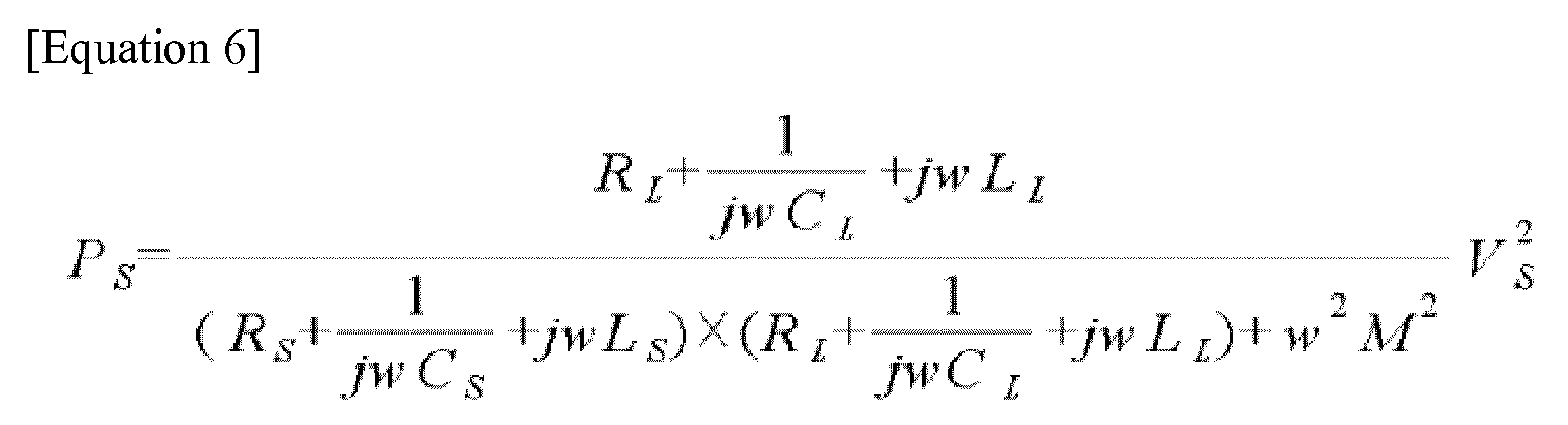
- Equation 7 that expresses a power transfer function K indicating the efficiency of wirelessly transmitting power from the power supply device to the power pickup device is induced from
Equation 5 and Equation 6.
- Here, when applying, to the induced equation,


Equation 8 is obtained.
- Also,


Equation 8, Equation 9 may be established.
-
FIG. 10 illustrates a structure of an I-shaped power supply device. - A power supply device may supply power to a moving body using a magnetic induction method and a power pickup device may be attached to the moving body to collect power from the power supply device using a magnetic induction method and to charge a battery.
FIG. 10 illustrates atop view 31, aside view 32, and afront view 33 of the I-shaped power supply device and the power pickup device to collect the power from the I-shaped power supply device in a cross-sectional form. -
FIG. 10 illustrates a case in which the power supply device is laid under aroad 1 as an embodiment of the I-shaped power supply device. - The I-shaped power supply device includes a
power supply core 1011 including a plurality ofmagnetic poles 1012 disposed in series along a heading direction of the moving body and apower line 1020 disposed so that neighboringmagnetic poles 1012 of thepower supply core 1011 may have different polarities, that is, so that N pole and S pole may alternately occur. In the embodiment ofFIG. 10 , currents towards opposite directions flow in thepower lines 1020. Accordingly, as illustrated in theside view 32,magnetic fields 50 towards opposite directions may be formed above the continuousmagnetic poles 1012 and thus, the N pole and the S pole may alternately occur. In such a manner, the power may be supplied to the moving body traveling above using a magnetic induction method. Apower pickup device 1040 may collect the power from the power supply device. Calling "I shape" is because a cross-section of themagnetic pole 1012 is provided in an "I" shape as illustrated in thefront view 33. However, other shapes slightly modified and enhanced from the "I" shape may be sufficiently possible, which may also be referred to as the "I shape". - As illustrated in
FIG. 10 , a power supply core may have a width perpendicular to a heading direction of a moving body less than or equal to a half of an interval between centers ofmagnetic poles 1012. As described above, by providing amagnetic pole 1012 in an I shape, it is possible to significantly decrease the width of themagnetic pole 1012 and to alternately generate the N pole and the S pole in a heading direction of a road. Accordingly, it is possible to significantly decrease an electromagnetic field (EMF) on the left and the right of a power line, and to reduce installation cost of the power line. Further, a distance between a power supply device laid underground and apower pickup device 1040 installed in a lower portion of a vehicle, that is, agap interval 1031 ofFIG. 11 may be maintained to be greater than or equal to a predetermined interval and power may be appropriately supplied. Also, due to a narrow width of a power line using a narrow I-shaped magnetic pole, it is possible to reduce left and right widths of thepower pickup device 1040 installed in the vehicle. When thepower pickup device 1040 has at least predetermined left and right widths within the above range, it is possible to increase left and right tolerance deviations compared to a power line in a different structure. Accordingly, a wide left and right tolerance characteristic compared to the different structure may be achieved. - Also, as illustrated in
FIG. 10 , a length of themagnetic pole 1012 towards the heading direction of the moving body may be two folds or more of a distance between an end portion of the magnetic pole and an end portion of a magnetic pole adjacent thereto. - A
power supply core 1011 may be provided in a form in which power supply modules, each including at least onemagnetic pole 1012 disposed in series along the heading direction of the moving body, are disposed to constitute a column in series. That is, apower supply core 1011 including amagnetic pole 1012 may be modulated and the respective modules may be connected in series. -
FIG. 11 illustrates an embodiment in which apower pickup core 1051 of apower pickup device 1050 is provided in a form of a lattice. - The above structure may reduce a weight of the
power pickup core 1051 and may be advantageous in cooling and readily manufacturing thepower pickup core 1051 in a mechanical solid structure. If an interval between bars is less than or equal to a half of thegap interval 1031 that is sufficiently small, no great affect may be applied to electrical performance. -
FIG. 12 illustrates a power supply module modulated in a size corresponding to an interval between magnetic poles to easily install a power supply device on a bent road. - A
top view 1210 and aside view 1220 of each power supply core module are illustrated.Core connecting members top view 1230 and aside view 1240 illustrate a form in which the power supply core modules are connected using thecore connecting members -
FIG. 13 illustrates an embodiment of a structure for coping with expansion and shrinkage that occurs due to a change of a power supply device in temperature. -
FIG. 13 illustrates atop view 1310, aside view 1330, and alength 1311 of a power supply core in a case in which the power supply device is thermally shrunk. Also,FIG. 13 illustrates atop view 1320, aside view 1340, and alength 1321 of a power supply core, and afront view 1350 in a case in which the power supply device is thermally expanded. - A road needs to tolerate a change of about -20 degrees to +80 degrees. Aspects that a magnetic material or a cable constituting the power supply device, a cable protecting mechanical such as a fiber reinforced plastic (FRP) or a PVC pipe, and asphalt or cement are thermally expanded and thermal expansion coefficients are different need to be considered. Also, during the above process, a waterproof characteristic may need to be maintained in a good condition.
- Accordingly, the respective structures are discrete at predetermined inetrvals along the heading direction of the road and maintaining the connecting surface between the structures to be waterproof becomes an issue.
FIG. 13 illustrates an example in which acore connecting member 1332 made of the same magnetic material is provided betweenpower supply cores 1331 in the heading direction of the roads. Also,FIG. 13 illustrates a case in which anFRP 1333 is disconnected and thereby coupled and a coupling portion thereof is processed using an O-ring 1334. A shrinkage tube or a bond coupling may be used for coupling an FRP or a polyvinyl chloride (PVC) pipe. Also, there is no need to connect the FRP or the PVC pipe each time using an elastic connecting member. The elastic connecting member may be used every one time per a few meters to tens of meters. Here, a general cable is flexible and thus, may not require the aforementioned countermeasure separately. -
FIG. 14 illustrates a structure of a W-shaped power supply device. -
FIG. 14 illustrates atop view 41, aside view 42, and afront view 43 of the W-shaped power supply device and a power pickup device to collect power from the W-shaped power supply device. -
FIG. 14 illustrates a case in which the W-shaped power supply device is laid under a road as an embodiment of the W-shaped power supply device. - The W-shaped power supply device includes a
power supply core 1111 disposed to be in parallel with a heading direction of a moving body and including a plurality ofmagnetic poles 1112 disposed to be in parallel with each other, and apower line 1120 extending along the heading direction of the moving body so that neighboring magnetic poles of the power supply core may have different polarities on a surface perpendicular to the heading direction of the moving body, that is, so that N pole and S pole may alternately occur. In a case of the embodiment ofFIG. 14 , as illustrated in thefront view 43, currents towards opposite directions flow in the twopower lines 1120. Also, as illustrated in thefront view 43,magnetic fields 60 towards opposite directions may be formed above themagnetic poles 1112 in parallel with the heading direction of the moving body and extending in parallel with each other and thus, the N pole and the S pole may alternately occur. In such a manner, the power may be supplied to the moving body traveling above using a magnetic induction method and apower pickup device 1140 may collect the power. Calling "W shape" is because a cross-section of thepower supply core 1111 including themagnetic pole 1112 is provided in a "W" shape as illustrated in thefront view 43. However, other shapes slightly modified and enhanced from the "W" shape may be sufficiently possible, which may also be referred to as the "W" shape". For example, referring to thefront view 43, no magnetic pole stands in the middle and thus, only two magnetic poles stand in parallel with each other at both sides and thus, only a single pair of N pole and S pole may be present. In this example, although the corresponding shape may be close to a "U" shape, it will be generally referred to as a W shape. The W-shaped power supply device may be provided in a form in which power supply cores of a U-shaped power supply device are disposed to be adjacent to each other in parallel with the heading direction of the moving body. - A power supply core may be provided in a form in which power modules, disposed to be in parallel with the heading direction of the moving body and each including a plurality of magnetic poles in parallel with each other, are disposed in series along the heading direction of the moving body. That is, a power supply core including a magnetic pole may be modulated and the respective modules may be connected in series.
-
FIG. 15 is a view describing a magnetic shielding method of an I-shaped power supply device and a power pickup device. - An I-shaped power pickup device may have a size that is reduced by about a half of a car width and thus, may have a spatial room for magnetic shielding. Accordingly, when a looped
magnetic shielding material 1501 surrounds around the I-shaped power supply device, leakage magnetic flux is magnetically grounded along themagnetic shielding loop 1501 and thus, a magnetic shielding effect may be achieved. Magnetic shielding may be achieved only along the side surface and may be achieved by covering a top surface. - In a case of the I-shaped power supply device, magnetic poles may alternately change at predetermined intervals and an electromagnetic field (EMF) may be formed in a lateral direction. Accordingly, when an I-shaped
magnetic shielding line 1502 is provided in a lengthwise direction, magnetic ground may be performed in the lengthwise direction and a magnetic shielding effect may be achieved. -
FIG. 16 is a graph and a table showing a transmission efficiency according to a Q factor (Qs) of a power supply device in a case in which a resonant frequency of a power supply and pickup system is 20 kHz and a current signal of 20 kHz is applied as an operating frequency. - A resonant frequency of the system may vary based on a manufacturing process and may also vary based on an error of a part being used. In particular, in a case in which a power supply device is fixed and a power pickup device is mobile such as a wireless charging electric vehicle, or in a case in which a single power supply device is present and an additional power pickup device further collects power, the resonant frequency of the system may vary.
-
FIG. 16 illustrates a case in which a resonant frequency and an operating frequency match at 20 kHz. It can be known fromFIG. 16 that in a case in which QS is greater than 100 (QS = 115), a power transmission efficiency at the operating frequency is slightly enhanced compared to a case in which QS is less than 100 (Qs = 14.24) (0.872 --> 0.880, see the table disposed at the bottom ofFIG. 16 ). However, if the operating frequency and the resonant frequency differ, a case in which QS is less than 100 is further advantageous in an aspect of a power transfer sensitivity compared to a case in which QS is greater than 100, which is illustrated inFIG. 17 and will be described below. -
FIG. 17 is a graph and a table showing a transmission efficiency according to a Q factor (Qs) of a power supply device in a case in which a resonant frequency of a power supply and pickup system is 18 kHz and a current signal of 20 kHz is applied as an operating frequency. - As described above with reference to
FIG. 16 , in a case in which a resonant frequency of a power supply and pickup system matches an operating frequency of an applied signal, it may not greatly affect the Q factor and a high power transfer function may be maintained. However, in a case in which the Q factor is relatively great, a width of a frequency band becomes narrow and thus, a transmission efficiency may significantly vary based on the operating frequency. - Referring to
FIG. 17 , if the resonant frequency is deviated from the operating frequency, a case in which QS is less than 100 (QS = 12.82) shows a further enhanced transmission efficiency at the corresponding operating frequency of 20 kHz compared to a case in which QS is greater than 100 (QS = 115) (0.055 --> 0.512, see the table disposed at the bottom ofFIG. 17 ). As described above, if the resonant frequency of 18 kHz is deviated from the operating frequency of 20 kHz and thereby shakes, a case in which Qs is less than 100 (Qs = 12.82) is less sensitive to a change in the transmission efficiency of the wireless power transfer system compared to a case in which Qs is greater than 100 (Qs = 115) and thus, may achieve a further enhanced stability. - As described above, in a case in which a power supply device is fixed and a power pickup device is mobile and thus, power supply and pickup locations are easy to be twisted such as a wireless charging electric vehicle, or in a case in which a single power supply device is present and an additional power pickup device further collects power, it may be desirable to use a Q factor value of the power supply device to be less than or equal to 100 for the efficiency and stability of power transfer. Also, in a case of a large power system such as power supply and pickup for vehicle, an internal pressure at which a part is tolerable is also a very important element. Accordingly, in the present invention, to achieve the above purpose, it may be desirable to use a Q factor value of the power supply device to be less than or equal to 100.
-
FIG. 18 is a graph and a table showing a transmission efficiency according to a Q factor (QL) of a power pickup device in a case in which a resonant frequency of a power supply and pickup system is 20 kHz and a current signal of 20 kHz is applied as an operating frequency.FIG. 18 illustrates a case in which a resonant frequency and an operating frequency match at 20 kHz. It can be known fromFIG. 18 that in a case in which QL is greater than 100 (QL = 115), a power transmission efficiency at the operating frequency is slightly enhanced compared to a case in which QL is less than 100 (QL = 12.4) (0.873 --> 0.894, see the table disposed at the bottom ofFIG. 18 ). However, if the operating frequency and the resonant frequency differ, a case in which QL is less than 100 is further advantageous in an aspect of a power transfer sensitivity compared to a case in which QL is greater than 100, which is illustrated inFIG. 19 and will be described below. -
FIG. 19 is a graph and a table showing a transmission efficiency according to a Q factor (QL) of a power pickup device in a case in which a resonant frequency of a power supply and pickup system is 18 kHz and a current signal of 20 kHz is applied as an operating frequency. As described above, if the resonant frequency of 18 kHz is deviated from the operating frequency of 20 KHz, a case in which QL is less than 100 (QL = 11.2) shows a further enhanced transmission efficiency at the corresponding operating frequency of 20 kHz compared to a case in which QL is greater than 100(QL = 115) (0.003 --> 0.094, see the table disposed at the bottom ofFIG. 19 ). As described above, if the resonant frequency is deviated from the operating frequency of 20 kHz and thereby shakes, a case in which QL is less than 100 (QL = 11.2) is less 1sensitive to a change in the transmission efficiency of the wireless power transfer system compared to a case in which QL is greater than 100 (QL = 115) and thus, may achieve a further enhanced stability. - Although a few embodiments of the present invention have been shown and described, the present invention is not limited to the described embodiments. Instead, it would be appreciated by those skilled in the art that changes may be made to these embodiments without departing from the principles and spirit of the invention, the scope of which is defined by the claims and their equivalents.
Claims (17)
- A power supply device for supplying power to a moving body using a magnetic induction method, the power supply device comprising:a power supply core comprising a magnetic pole to form a magnetic field in a predetermined direction; anda power supply coil disposed so that neighboring magnetic poles of the power supply core have different polarities, and in which a current flows,wherein a Q factor by the power supply coil current is less than 100 and the Q
factor is determined by where w denotes an angular frequency of the power supply coil current, LS denotes inductance of the power supply coil, and RS denotes resistance of the power supply coil.
 - A power supply device for supplying power to a moving body using a magnetic induction method, the power supply device comprising:a power supply core disposed to be in parallel with a heading direction of the moving body and comprising a plurality of magnetic poles disposed to be in parallel with each other; anda power supply coil extending along the heading direction of the moving body, and in which a current flows so that neighboring magnetic poles of the power supply core have different polarities on a surface perpendicular to the heading direction of the moving body,wherein a Q factor by the power supply coil current is less than 100 and the Q
factor is determined by where w denotes an angular frequency of the power supply coil current, LS denotes inductance of the power supply coil, and RS denotes resistance of the power supply coil.
 - The power supply device of claim 2, wherein a cross-section of the magnetic pole perpendicular to the heading direction of the moving body has a "U" shape, and
the power supply coil is disposed within the U-shaped magnetic pole to be in parallel with the heading direction of the moving body. - The power supply device of claim 2, wherein a cross-section of the magnetic pole perpendicular to the heading direction of the moving body has a shape in which two "U"s are horizontally adjacent to each other, and
the power supply coil is disposed to be in parallel with the heading direction of the moving body within each U-shaped magnetic pole. - The power supply device of claim 2, wherein the power supply core is provided in a form in which power supply modules, disposed to be in parallel with the heading direction of the moving body and each comprising a plurality of magnetic poles in parallel with each other, are disposed in series.
- A power supply device for supplying power to a moving body using a magnetic induction method, the power supply device comprising:a power supply core comprising at least one magnetic pole disposed in series along a heading direction of the moving body; andpower supply coils disposed to be in parallel with the heading direction of the moving body based on the left and the right of the magnetic pole and to intersect each other between the magnetic poles and in which a current flows so that neighboring magnetic poles of the power supply core have different polarities,wherein a Q factor by the power supply coil current is less than 100 and the Q
factor is determined by where w denotes an angular frequency of the power supply coil current, LS denotes inductance of the power supply coil, and RS denotes resistance of the power supply coil.
 - The power supply device of claim 6, wherein a cross-section of the magnetic pole perpendicular to the heading direction of the moving body is provided in a "T" shape, and
the power supply coils are disposed to be in parallel with the heading direction of the moving body on the left and right of each magnetic pole and to intersect each other between the magnetic poles, and
currents towards opposite directions flow in the power supply coils disposed on the left and the right of each magnetic pole. - The power supply device of claim 6, further comprising:a linear magnetic shielding member disposed in a heading direction of a road.
- The power supply device of claim 6, wherein the power supply core is provided in a form in which power supply modules, each comprising at least one magnetic pole disposed in series along the heading direction of the moving body, are disposed to constitute a column in series.
- The power supply device of claim 9, wherein each of the power supply modules comprises core connecting members at a front end and a rear end, and
power supply core modules are connected to each other using the core connecting members and disposed to constitute a column in series along a heading direction of a road. - The power supply device of claim 9, wherein the power supply core are disposed to be separate from each other at predetermined intervals to be capable of accommodating a thermal expansion and a thermal shrinkage.
- The power supply device of claim 9, wherein a fiber reinforced plastic (FRP) is installed in an upper portion or a lower portion of the power supply core.
- The power supply device of claim 6, wherein the power supply core has a width perpendicular to the heading direction of the moving body less than or equal to a half of an interval between centers of the magnetic poles.
- The power supply device of claim 6, wherein a length of the magnetic pole towards the heading direction of the moving body is two folds or more of a distance between an end portion of the magnetic pole and an end portion of a magnetic pole adjacent thereto.
- A power pickup device to be supplied with power from a power supply device disposed along a heading direction of a moving body and installed in the moving body, the power pickup device comprising:a power pickup core disposed at a lower end of the moving body to be separate from the power supply device by a predetermined interval; anda power pickup coil disposed in the power pickup core in a loop form to flow an induction current induced from the power supply device,wherein a Q factor by the power pickup coil current is less than 100 and the Q
factor is determined by where w denotes an angular frequency of the power pickup coil current, LL denotes inductance of the power pickup coil, and RL denotes resistance of the power pickup coil.
 - The power pickup device of claim 15, wherein the power pickup core is provided in a form of a plate or a lattice.
- The power pickup device of claim 15, further comprising:a magnetic shielding member provided in a loop shape around the power pickup core.
Applications Claiming Priority (2)
| Application Number | Priority Date | Filing Date | Title |
|---|---|---|---|
| KR20110097190 | 2011-09-26 | ||
| PCT/KR2012/007723 WO2013048092A2 (en) | 2011-09-26 | 2012-09-25 | Power supply and pickup system capable of maintaining stability of transmission efficiency despite changes in resonant frequency |
Publications (2)
| Publication Number | Publication Date |
|---|---|
| EP2763281A2 true EP2763281A2 (en) | 2014-08-06 |
| EP2763281A4 EP2763281A4 (en) | 2016-01-20 |
Family
ID=47996600
Family Applications (1)
| Application Number | Title | Priority Date | Filing Date |
|---|---|---|---|
| EP12837326.3A Withdrawn EP2763281A4 (en) | 2011-09-26 | 2012-09-25 | CAPTURE POWER SUPPLY SYSTEM TO MAINTAIN STABILITY OF TRANSMISSION EFFICIENCY INSTEAD OF RESONANT FREQUENCY CHANGES |
Country Status (8)
| Country | Link |
|---|---|
| US (3) | US10230268B2 (en) |
| EP (1) | EP2763281A4 (en) |
| JP (1) | JP2014535254A (en) |
| KR (1) | KR101379792B1 (en) |
| CN (1) | CN103931079B (en) |
| AU (1) | AU2012317038B2 (en) |
| SG (1) | SG11201400970YA (en) |
| WO (1) | WO2013048092A2 (en) |
Cited By (1)
| Publication number | Priority date | Publication date | Assignee | Title |
|---|---|---|---|---|
| WO2016167667A1 (en) | 2015-04-17 | 2016-10-20 | 3I Innovation Limited | Inductive power transfer apparatus with improved coupling |
Families Citing this family (17)
| Publication number | Priority date | Publication date | Assignee | Title |
|---|---|---|---|---|
| US10230268B2 (en) * | 2011-09-26 | 2019-03-12 | Korea Advanced Institute Of Science And Technology | Power supply and pickup system capable of maintaining stability of transmission efficiency despite changes in resonant frequency |
| JP2014241673A (en) * | 2013-06-11 | 2014-12-25 | 株式会社東芝 | Electromagnetic wave leakage prevention device |
| JP6485735B2 (en) * | 2014-02-18 | 2019-03-20 | パナソニックIpマネジメント株式会社 | Non-contact power feeding device |
| FR3019112B1 (en) * | 2014-03-25 | 2016-05-06 | Alstom Transp Tech | GROUND FEED SYSTEM FOR NON-GUIDED ELECTRIC VEHICLES AND METHOD OF USING THE SAME |
| TWI584018B (en) | 2014-08-03 | 2017-05-21 | 帕戈技術股份有限公司 | Wearable camera systems and apparatus and method for attaching camera systems or other electronic devices to wearable articles |
| KR101741768B1 (en) * | 2015-04-14 | 2017-05-31 | 한국과학기술원 | Apparatus for Wide Area Wireless Power Transmission and Reception |
| KR20170118054A (en) | 2014-12-23 | 2017-10-24 | 포고텍, 인크. | Wireless camera systems and methods |
| US10241351B2 (en) | 2015-06-10 | 2019-03-26 | PogoTec, Inc. | Eyewear with magnetic track for electronic wearable device |
| CA3041583A1 (en) * | 2015-10-29 | 2017-05-04 | PogoTec, Inc. | Hearing aid adapted for wireless power reception |
| US11558538B2 (en) | 2016-03-18 | 2023-01-17 | Opkix, Inc. | Portable camera system |
| US10329942B2 (en) * | 2017-01-16 | 2019-06-25 | Natural Gas Solutions North America, Llc | Apparatus using magnets for harvesting energy on a metrology device |
| FR3065403B1 (en) * | 2017-04-25 | 2021-02-12 | Alstom Transp Tech | SET CONSISTS OF A GROUND POWER SYSTEM AND AN ELECTRIC VEHICLE |
| FR3065405B1 (en) * | 2017-04-25 | 2021-02-12 | Alstom Transp Tech | ELASTOMERIC CONDUCTIVE TRACK SUPPORT WITH RECTANGULAR SECTION FOR GROUND ELECTRICAL SUPPLY SYSTEM |
| WO2020102237A1 (en) | 2018-11-13 | 2020-05-22 | Opkix, Inc. | Wearable mounts for portable camera |
| KR102789718B1 (en) * | 2022-08-03 | 2025-04-03 | 주식회사 반프 | Wireless power transmission system for optimal power transmission and optimal resonance frequency control method of the system |
| KR102815620B1 (en) * | 2022-08-12 | 2025-06-04 | 울산과학기술원 | Double-Track Self-Grounding Wireless Charging Method and System for Charging Electric Vehicles While Driving |
| KR102815414B1 (en) * | 2023-11-14 | 2025-05-30 | 박종부 | Electric vehicle wireless charging road system including electric vehicle wireless charging unit |
Family Cites Families (21)
| Publication number | Priority date | Publication date | Assignee | Title |
|---|---|---|---|---|
| US4836344A (en) * | 1987-05-08 | 1989-06-06 | Inductran Corporation | Roadway power and control system for inductively coupled transportation system |
| JPH0678406A (en) * | 1992-08-28 | 1994-03-18 | Daifuku Co Ltd | Noncontact power feeding equipment for moving body |
| WO1995011545A1 (en) * | 1993-10-21 | 1995-04-27 | Auckland Uniservices Limited | Inductive power pick-up coils |
| JPH09312902A (en) * | 1996-05-21 | 1997-12-02 | Hitachi Ltd | Non-contact power supply device |
| JP2002137659A (en) * | 2000-08-23 | 2002-05-14 | Shinko Electric Co Ltd | Non-contact power supply |
| JP3906708B2 (en) * | 2002-02-25 | 2007-04-18 | 松下電工株式会社 | Non-contact power transmission device |
| JP2004120880A (en) * | 2002-09-25 | 2004-04-15 | Tsubakimoto Chain Co | Non-contact power feeding device and traveling body |
| JP4356844B2 (en) * | 2006-10-05 | 2009-11-04 | 昭和飛行機工業株式会社 | Non-contact power feeding device |
| US8105247B2 (en) * | 2008-07-25 | 2012-01-31 | Buchwald O'dea Llc | Device for monitoring size of luminal cavity |
| WO2010057799A1 (en) * | 2008-11-18 | 2010-05-27 | Huebner Burkhard | Device for transmitting electrical energy |
| KR100976158B1 (en) * | 2008-12-12 | 2010-08-16 | 주식회사 한림포스텍 | Solid-state power receiver with planar spiral core power transformer PC core |
| CN101828320B (en) * | 2008-12-12 | 2013-04-10 | 郑春吉 | Non-contact charging station, non-contact power receiving device and control method thereof |
| EP2394345B1 (en) * | 2009-02-05 | 2019-08-07 | Auckland UniServices Limited | Inductive power transfer apparatus |
| KR100944113B1 (en) * | 2009-02-27 | 2010-02-24 | 한국과학기술원 | Power supply system and method for electric vehicles |
| KR101040662B1 (en) * | 2009-04-06 | 2011-06-13 | 한국과학기술원 | Ultra slim power supply and collector device for electric vehicle |
| WO2011074894A2 (en) * | 2009-12-16 | 2011-06-23 | 한국과학기술원 | Modular electric-vehicle electricity supply device and electrical wire arrangement method |
| EP2516204A2 (en) * | 2009-12-24 | 2012-10-31 | Rusk Intellectual Reserve AG | Electric vehicle and electric supply arrangement for the same |
| JP2011142724A (en) * | 2010-01-06 | 2011-07-21 | Hitachi Ltd | Noncontact power transmission device and near field antenna for same |
| KR100976319B1 (en) * | 2010-04-07 | 2010-08-16 | 박준남 | Consecutive power supply system using non-contact power supplying device |
| KR101038350B1 (en) * | 2010-05-04 | 2011-05-31 | (주)그린파워 | Contactless power transmission device for electric vehicles |
| US10230268B2 (en) * | 2011-09-26 | 2019-03-12 | Korea Advanced Institute Of Science And Technology | Power supply and pickup system capable of maintaining stability of transmission efficiency despite changes in resonant frequency |
-
2012
- 2012-09-25 US US14/347,235 patent/US10230268B2/en active Active
- 2012-09-25 KR KR1020120106773A patent/KR101379792B1/en active Active
- 2012-09-25 JP JP2014533194A patent/JP2014535254A/en active Pending
- 2012-09-25 SG SG11201400970YA patent/SG11201400970YA/en unknown
- 2012-09-25 CN CN201280055947.1A patent/CN103931079B/en active Active
- 2012-09-25 EP EP12837326.3A patent/EP2763281A4/en not_active Withdrawn
- 2012-09-25 WO PCT/KR2012/007723 patent/WO2013048092A2/en not_active Ceased
- 2012-09-25 AU AU2012317038A patent/AU2012317038B2/en active Active
-
2019
- 2019-01-15 US US16/247,766 patent/US10476303B2/en active Active
- 2019-01-15 US US16/247,794 patent/US10483799B2/en active Active
Cited By (2)
| Publication number | Priority date | Publication date | Assignee | Title |
|---|---|---|---|---|
| WO2016167667A1 (en) | 2015-04-17 | 2016-10-20 | 3I Innovation Limited | Inductive power transfer apparatus with improved coupling |
| EP3284095A4 (en) * | 2015-04-17 | 2019-05-22 | 3i Innovation Limited | INDUCTIVE POWER TRANSFER APPARATUS WITH ENHANCED COUPLING |
Also Published As
| Publication number | Publication date |
|---|---|
| AU2012317038B2 (en) | 2014-10-30 |
| WO2013048092A2 (en) | 2013-04-04 |
| US20140319927A1 (en) | 2014-10-30 |
| US20190207421A1 (en) | 2019-07-04 |
| AU2012317038A1 (en) | 2014-05-08 |
| WO2013048092A3 (en) | 2013-05-23 |
| KR101379792B1 (en) | 2014-04-02 |
| CN103931079A (en) | 2014-07-16 |
| EP2763281A4 (en) | 2016-01-20 |
| US10230268B2 (en) | 2019-03-12 |
| US20190267839A1 (en) | 2019-08-29 |
| US10483799B2 (en) | 2019-11-19 |
| JP2014535254A (en) | 2014-12-25 |
| CN103931079B (en) | 2017-08-22 |
| US10476303B2 (en) | 2019-11-12 |
| SG11201400970YA (en) | 2014-09-26 |
| KR20130033332A (en) | 2013-04-03 |
Similar Documents
| Publication | Publication Date | Title |
|---|---|---|
| EP2763281A2 (en) | Power supply and pickup system capable of maintaining stability of transmission efficiency despite changes in resonant frequency | |
| JP7194091B2 (en) | Inductive power transfer device | |
| EP2394345B1 (en) | Inductive power transfer apparatus | |
| US8833533B2 (en) | Ultra slim power supply device and power acquisition device for electric vehicle | |
| EP2858206B1 (en) | Power reception device and power transmission device | |
| US10600564B2 (en) | Inductive power transfer system primary track topologies | |
| EP3131174B1 (en) | Non-contact power supply coil | |
| US9318258B2 (en) | Antenna coil comprising plurality of coil portions | |
| KR20180105747A (en) | Roadway powered electric vehicle system | |
| EP3269585A1 (en) | Vehicle comprising contactless power reception unit | |
| WO2013001636A1 (en) | Power transmitting device, power receiving device, and power transmission system | |
| GB2512864A (en) | Inductive power transfer pad and system for inductive power transfer | |
| US10720277B2 (en) | Ferrite arrangement in a wireless power-transfer structure to mitigate dimensional tolerance effects on performance | |
| US20230068912A1 (en) | Charging Road | |
| US9595382B2 (en) | Resonance coil, electric power transmission device, electric power receiving device, and electric power transmission system | |
| US20160028240A1 (en) | Inductive power transfer apparatus | |
| CN114274801B (en) | Output voltage fluctuation suppression method for three-phase dynamic wireless power supply system | |
| JP2020515037A (en) | Secondary structure of winding structure and method for manufacturing secondary structure |
Legal Events
| Date | Code | Title | Description |
|---|---|---|---|
| PUAI | Public reference made under article 153(3) epc to a published international application that has entered the european phase |
Free format text: ORIGINAL CODE: 0009012 |
|
| 17P | Request for examination filed |
Effective date: 20140425 |
|
| AK | Designated contracting states |
Kind code of ref document: A2 Designated state(s): AL AT BE BG CH CY CZ DE DK EE ES FI FR GB GR HR HU IE IS IT LI LT LU LV MC MK MT NL NO PL PT RO RS SE SI SK SM TR |
|
| DAX | Request for extension of the european patent (deleted) | ||
| A4 | Supplementary search report drawn up and despatched |
Effective date: 20151217 |
|
| RIC1 | Information provided on ipc code assigned before grant |
Ipc: B60L 11/18 20060101ALI20151211BHEP Ipc: H02J 17/00 00000000AFI20151211BHEP Ipc: H01F 27/36 20060101ALI20151211BHEP Ipc: H02J 5/00 20160101ALI20151211BHEP Ipc: H02J 7/00 20060101ALI20151211BHEP Ipc: H01F 38/14 20060101ALI20151211BHEP Ipc: B60M 7/00 20060101ALI20151211BHEP Ipc: B60L 9/28 20060101ALI20151211BHEP |
|
| 17Q | First examination report despatched |
Effective date: 20170703 |
|
| STAA | Information on the status of an ep patent application or granted ep patent |
Free format text: STATUS: THE APPLICATION IS DEEMED TO BE WITHDRAWN |
|
| 18D | Application deemed to be withdrawn |
Effective date: 20171114 |