EP2763258A1 - Terminal platform - Google Patents
Terminal platform Download PDFInfo
- Publication number
- EP2763258A1 EP2763258A1 EP14151852.2A EP14151852A EP2763258A1 EP 2763258 A1 EP2763258 A1 EP 2763258A1 EP 14151852 A EP14151852 A EP 14151852A EP 2763258 A1 EP2763258 A1 EP 2763258A1
- Authority
- EP
- European Patent Office
- Prior art keywords
- terminal
- platform
- main body
- support
- bracket
- Prior art date
- Legal status (The legal status is an assumption and is not a legal conclusion. Google has not performed a legal analysis and makes no representation as to the accuracy of the status listed.)
- Granted
Links
Images



Classifications
-
- H—ELECTRICITY
- H02—GENERATION; CONVERSION OR DISTRIBUTION OF ELECTRIC POWER
- H02G—INSTALLATION OF ELECTRIC CABLES OR LINES, OR OF COMBINED OPTICAL AND ELECTRIC CABLES OR LINES
- H02G3/00—Installations of electric cables or lines or protective tubing therefor in or on buildings, equivalent structures or vehicles
- H02G3/30—Installations of cables or lines on walls, floors or ceilings
-
- H—ELECTRICITY
- H01—ELECTRIC ELEMENTS
- H01R—ELECTRICALLY-CONDUCTIVE CONNECTIONS; STRUCTURAL ASSOCIATIONS OF A PLURALITY OF MUTUALLY-INSULATED ELECTRICAL CONNECTING ELEMENTS; COUPLING DEVICES; CURRENT COLLECTORS
- H01R9/00—Structural associations of a plurality of mutually-insulated electrical connecting elements, e.g. terminal strips or terminal blocks; Terminals or binding posts mounted upon a base or in a case; Bases therefor
- H01R9/16—Fastening of connecting parts to base or case; Insulating connecting parts from base or case
-
- H—ELECTRICITY
- H02—GENERATION; CONVERSION OR DISTRIBUTION OF ELECTRIC POWER
- H02G—INSTALLATION OF ELECTRIC CABLES OR LINES, OR OF COMBINED OPTICAL AND ELECTRIC CABLES OR LINES
- H02G15/00—Cable fittings
- H02G15/02—Cable terminations
Definitions
- Japanese Pub. Patent App. 2009-170357 discloses a terminal platform as an electric connection box that supports a terminal fitting that is bent in a substantially L shape.
- the terminal fitting is provided with (i) a portion that is fixed to an upper surface of the terminal platform via a fixing member such as a bolt and (ii) a portion that is arranged along a side surface of the terminal platform and is connected to wiring.
- the above-described terminal platform may be fixed to a metal bracket.
- a lock portion is arranged on a side surface of the terminal platform, and a mounting piece engageable to the lock portion is protrudingly arranged on the bracket, there is a possibility that the terminal platform may not be stably supported by the bracket, and when a fixing force of a fixing member acts on an upper surface of the terminal platform, the mounting piece separates from the lock portion and the terminal platform may fall from the bracket.
- the bracket is placed at a position close to the terminal fitting, there is also a possibility that the terminal fitting and the bracket may contact each other and a short circuit may be generated.
- An object is to provide a terminal platform that stably supports a bracket and avoids electrical contact between a terminal fitting and a bracket.
- a resin terminal platform supports a terminal fitting having (i) a wire connection portion to be connected to wiring and (ii) a terminal main body that extends in a direction intersecting the wire connection portion, and that is provided with a platform main body including (i) a support-receiving portion that is supported by a support portion formed on a metal bracket, (ii) a terminal fixing portion that is positioned at a side opposite to the support-receiving portion and fixes the terminal main body of the terminal fitting, and (iii) a surface portion that is arranged at a side intersecting the terminal fixing portion and the support-receiving portion, and that extends along the wire connection portion of the terminal fitting, and a partition wall that extends to the surface portion of the platform main body and is arranged facing a tip end of the support portion.
- the terminal fixing portion of the platform main body is positioned at a side facing the support-receiving portion that is supported by the support portion of the bracket.
- a fixing force that acts on the terminal fixing portion is directly transmitted to and received by the support portion through the support-receiving portion. Therefore, the terminal platform is stably supported by the bracket.
- the tip end of the support portion is positioned near the wire connection portion of the terminal fitting and that the bracket and the terminal fitting may electrically contact each other.
- the partition wall of the terminal platform is arranged facing the tip end of the support portion, whereby the support portion and the wire connection portion are separated by the partition wall, so electrical contact between the bracket and the terminal fitting is avoided, and electrical conduction reliability of the wire connection portion is ensured.
- a plurality of the terminal fittings may be supported on the surface portion of the platform main body, and a partition wall is arranged, which separates the wire connection portions that are adjacent in a width direction. By the partition wall, electrical contact between the adjacent wire connection portions is avoided.
- the partition wall may extend out from the platform main body, and when the platform main body is assembled to the bracket in a reversed orientation that is opposite to the normal orientation, a tip end of the partition wall contacts the support portion of the bracket so as to restrict assembly beyond that point. Because the tip end of the partition wall contacts the support portion of the bracket, erroneous assembly of the terminal platform is suppressed. Furthermore, because the structure that suppresses erroneous assembly is constituted by the partition wall, a special structure for suppressing erroneous assembly is not needed, and the structure can be simplified.
- Embodiment 1 is explained with reference to Figs. 1-8 .
- a terminal platform 10 of embodiment 1 is an example of a connecting terminal platform that relays a power line of an automobile.
- the terminal platform 10 is supported by a metal bracket 60, and further, terminal fittings 40 are fixed to the terminal platform 10. Additionally, in the following explanation, with respect to front and rear directions, the right side of Fig. 1 is the front side. With respect to vertical directions, Fig. 1 is used as a reference.
- the bracket 60 is metal and is molded by bending a flat plate material as shown in Fig. 7 .
- the bracket 60 is constituted by a base plate portion 61 that is fixed to an installation surface of an undepicted vehicle, a transition portion 62 that connects to an upper end of the base plate portion 61 and bends out from an upper end of the base plate portion 61 at an obtuse angle, a support portion 63 that connects to an upper end of the transition portion 62 and bends out from the upper end of the transition portion 62 at an obtuse angle, and a pair of attachment portions 64 that are bent up from both side edges of the support portion 63 substantially at right angles.
- the base plate portion 61 is fixed to an installation surface of an undepicted vehicle by bolts, and has a plurality of through-holes 65 through which the bolts pass.
- the support portion 63 is arranged substantially horizontally along a front-to-rear direction.
- the two attachment portions 64 are at positions shifted relative to each other in the front-to-rear direction at the two side edges of the support portion 63.
- One of the attachment portions 64 is positioned at a front end of one side edge of the support portion 63, and the other attachment portion 64 is positioned at an intermediate portion, in the front-to-rear direction, of the other side edge of the support portion 63.
- substantially rectangular attachment holes 66 are provided in both of the attachment portions 64.
- the terminal fittings 40 are of metal plate material and are bent into a substantially L shape. As shown in Figs. 2-4 , in a state in which the terminal fittings 40 are fixed to the terminal platform 10, they have a terminal main bodies 41 that are arranged substantially horizontally along the front-to-rear direction, and wire connection portions 42 that are bent downward from the terminal main bodies 41 and are arranged substantially vertically along a vertical direction. The wire connection portions 42 are connected by crimping to wire cores 91 that are exposed at end portions of wires 90.
- the terminal main bodies 41 each have a connection hole 43 through which passes a stud bolt 13, described below (see Fig. 2 ). As shown in Fig. 3 , a pair of terminal fittings 40 is fixed to the terminal platform 10.
- the terminal platform 10 is of synthetic resin, and as shown in Fig. 1 , is provided with a box-shaped platform main body 11 and a cap-shaped cover 30 that covers the platform main body 11.
- a terminal fixing portion 12 for fixing the terminal main body 41 of both terminal fittings 40.
- stud bolts 13 which have a substantially cylindrical shape, and which form a pair in the width direction, are protrudingly arranged in the terminal fixing portion 12.
- a strip-shaped connection terminal 14 inserted so as to span across both stud bolts 13, is exposedly arranged in the terminal fixing portion 12.
- a peripheral wall 15 is protrudingly arranged, surrounding a periphery of the terminal fixing portion 12, excluding a rear end side at which the wire connection portions 42 are lead out (see Fig. 4 ).
- a pair of mounting holes 16 that pass through in a vertical direction, at positions shifted relative to each other in the front-to-rear direction at two width-direction sides, between which is the terminal fixing portion 12.
- a pair of elastic locking arms 17 is provided on the platform main body 11 so as to face the inside of both mounting holes 16.
- the elastic locking arms 17 extend diagonally upward in a cantilevered state from lower portions of the inside surfaces of the mounting holes 16, and can bendingly deform about the lower portions of the inside surfaces of the mounting holes 16 as a fulcrum.
- the attachment portions 64 of the bracket 60 are inserted into the mounting holes 16 from below, along inside surfaces of the mounting holes 16 (surfaces opposite to the surfaces at which the elastic locking arms 17 are connected). Leading end portions of the elastic locking arms 17 engage with the attachment holes 66 of the attachment portions 64, whereby the terminal platform 20 is locked to the bracket 60.
- a pair of window holes 18 at positions facing the elastic locking arms 17 (see Fig. 5 ). As shown in Figs. 1 and 5 , the elastic locking arms 17 can be viewed from the sides through the window holes 18. Additionally, as shown in Fig. 6 , a pair of lock portions 19 is protrudingly provided at upper end portions of outer surfaces of both sides of the platform main body 11. Later-described lock arms 31 of the cover 30 are engageable with both lock portions 19.
- a pair of support-receiving portions 21 that can abut against, and are supported by, the support portion 63 of the bracket 60.
- the support-receiving portions 21 are flat surfaces that are opposite, in a vertical direction, to the terminal fixing portion 12.
- a surface portion 22 is provided at a rear surface of the platform main body 11.
- the surface portion 22 is a flat surface that follows a direction perpendicular to surface directions of the terminal fixing portion 12 and the support-receiving portions 21, and is arranged so as to span from top to bottom from the terminal fixing portion 12 to the support-receiving portions 21.
- wire connection portions 42 of both terminal fittings 40 are arranged adjacent to each other, in the width direction, at the surface 22.
- a partition wall 23 that separates the two wire connection portions 42.
- the partition wall 23 is configured in a plate shape that extends in a vertical direction, and is arranged along a range that covers the entire crimp area of the wire connection portions 42.
- both protection walls 24 are configured in a plate shape that extends in a vertical direction. Lower ends of the protection walls 24 are arranged at the same height position as a lower end of the partition wall 23. The wire connection portions 42 of both terminal fittings 40 are covered and hidden from the side directions by the protection walls 24.
- the terminal platform 10 is provided with a partition wall 25 that extends downward from a lower end of the platform main body 11.
- the partition wall 25 has a flat plate configuration that connects coplanarly to the surface 22 and extends across an entire width of the platform main body 11. Additionally, the partition wall 25 is arranged along a range that covers the end portions of the wires 90. As shown in Fig. 2 , the partition wall 25 is arranged facing the tip end of the support portion 63 of the bracket 60, in a front-to-rear direction. Additionally, as shown in Fig. 5 , at a front surface of the partition wall 25, there is provided a plate-shaped protruding piece 26 that extends to the support-receiving portions 21. The protruding piece 26 is configured to extend substantially perpendicularly to the front surface of the partition wall 25.
- the cover 30 is mounted to the platform main body 11 from above, so as to cover both terminal fittings 40 and the wires 90.
- the pair of lock arms 31, which extend out in a downward direction from outer surfaces of both sides of the cover 30, are elastically engaged by the two lock portions 19, whereby the cover 30 is lockedly held to the platform main body 11 (see Fig. 1 ).
- the outer sides of the two protection walls 24 are covered by two side walls 32 of the cover 30.
- undepicted partition plates are provided that separate the terminal main bodies 41 of the two terminal fittings 40.
- the base plate portion 61 of the bracket 60 is fastened by bolts to an installation surface of an undepicted vehicle, and the bracket 60 is attached and fixed to the vehicle.
- the terminal platform 10 is placed on the support portion 63 of the bracket 60.
- the two attachment portions 64 of the bracket 60 are inserted into corresponding attachment holes 66 and elastically engaged with the elastic locking arms 17, the two attachment portions 64 of the bracket 60 are inserted into the mounting holes 16 of the platform main body 11, and the elastic locking arms 17 are inserted into, and elastically engaged with, the corresponding attachment holes 66 of the attachment portions 64, and the terminal platform 10 is mounted and fixed to the bracket 60.
- the partition wall 25 is between (i) the wire connection portions 42 of the terminal fittings 40 and (ii) the support portion 63, there is no electrical contact between the wire connection portions 42 and the support portion 63.
- the terminal main bodies 41 of the two terminal fittings 40 are fixed to the terminal fixing portion 12 of the platform main body 11.
- the stud bolts 13 are passed through the connection holes 43 of the terminal main bodies 41, and as shown in Fig. 3 , by fastening fixing members 50 such as nuts or the like to the stud bolts 13, the terminal main bodies 41 are fixed to the terminal fixing portion 12 of the platform main body 11.
- the terminal fixing portion 12 is pressed, and a downward fixing force acts on the platform main body 11, but because the support-receiving portions 21 of the platform main body 11 are supported by the support portion 63 of the bracket 60 at positions opposing the direction in which the fixing force acts, the terminal platform 10 does not fall off from the bracket 60.
- the two terminal fittings 40 are connected to the connection terminal 14 that is inserted into the terminal fixing portion 12, and the two terminal fittings 40 are short-circuited to each other and connected through the connection terminal 14.
- the cover 30 is put on the platform main body 11, and the periphery of both terminal fittings 40 and the connection terminal 14 is covered and protected by the cover 30.
- the terminal fixing portion 12 of the platform main body 11 is positioned at a side opposite to the support-receiving portions 21 that are supported by the support portion 63 of the bracket 60, the fixing force that acts on the terminal fixing portion 12 in connection with the fastening of the fixing members 50 is directly received by the support portion 63 through the support-receiving portions 21. Therefore, the terminal platform 10 is stably supported by the bracket 60.
- the partition wall 25 of the terminal platform 10 separates the tip ends of the support portion 63 from the wire connection portions 42, whereby electrical contact between the bracket 60 and the terminal fittings 40 is avoided. Therefore, electrical conduction reliability of the wire connection portions 42 is ensured.
- partition wall 23 provided on the surface 22 of the platform main body 11 separates the wire connection portions 42 of the two terminal fittings 40 that are adjacent in the width direction, electrical contact between the two terminal fittings 40 is also avoided.
- the terminal platform 10 is in an erroneous assembly orientation with respect to the bracket 60, the lower end of the partition wall 25 abuts against the support portion 63 of the bracket 60, and assembly beyond that point is restricted. Therefore, a condition of assembling the terminal platform 10 to the bracket 60 in an erroneous assembly orientation is avoided. Furthermore, because a structure that suppresses erroneous assembly is constituted by the partition wall 25, a special structure for suppressing erroneous assembly is not needed, and the overall structure can be simplified.
Landscapes
- Engineering & Computer Science (AREA)
- Architecture (AREA)
- Civil Engineering (AREA)
- Structural Engineering (AREA)
- Connections Arranged To Contact A Plurality Of Conductors (AREA)
Abstract
Description
- This application claims priority to Japanese Patent App. No.
JP 2013-019586 - Japanese Pub. Patent App.
2009-170357 - There are cases in which the above-described terminal platform may be fixed to a metal bracket. In those cases, for example, if a lock portion is arranged on a side surface of the terminal platform, and a mounting piece engageable to the lock portion is protrudingly arranged on the bracket, there is a possibility that the terminal platform may not be stably supported by the bracket, and when a fixing force of a fixing member acts on an upper surface of the terminal platform, the mounting piece separates from the lock portion and the terminal platform may fall from the bracket. Additionally, if the bracket is placed at a position close to the terminal fitting, there is also a possibility that the terminal fitting and the bracket may contact each other and a short circuit may be generated.
- An object is to provide a terminal platform that stably supports a bracket and avoids electrical contact between a terminal fitting and a bracket.
- A resin terminal platform supports a terminal fitting having (i) a wire connection portion to be connected to wiring and (ii) a terminal main body that extends in a direction intersecting the wire connection portion, and that is provided with a platform main body including (i) a support-receiving portion that is supported by a support portion formed on a metal bracket, (ii) a terminal fixing portion that is positioned at a side opposite to the support-receiving portion and fixes the terminal main body of the terminal fitting, and (iii) a surface portion that is arranged at a side intersecting the terminal fixing portion and the support-receiving portion, and that extends along the wire connection portion of the terminal fitting, and a partition wall that extends to the surface portion of the platform main body and is arranged facing a tip end of the support portion.
- The terminal fixing portion of the platform main body is positioned at a side facing the support-receiving portion that is supported by the support portion of the bracket. Thus, a fixing force that acts on the terminal fixing portion is directly transmitted to and received by the support portion through the support-receiving portion. Therefore, the terminal platform is stably supported by the bracket.
- Meanwhile, because of this structure, there is a concern that the tip end of the support portion is positioned near the wire connection portion of the terminal fitting and that the bracket and the terminal fitting may electrically contact each other. Thus, the partition wall of the terminal platform is arranged facing the tip end of the support portion, whereby the support portion and the wire connection portion are separated by the partition wall, so electrical contact between the bracket and the terminal fitting is avoided, and electrical conduction reliability of the wire connection portion is ensured.
- A plurality of the terminal fittings may be supported on the surface portion of the platform main body, and a partition wall is arranged, which separates the wire connection portions that are adjacent in a width direction. By the partition wall, electrical contact between the adjacent wire connection portions is avoided.
- The partition wall may extend out from the platform main body, and when the platform main body is assembled to the bracket in a reversed orientation that is opposite to the normal orientation, a tip end of the partition wall contacts the support portion of the bracket so as to restrict assembly beyond that point. Because the tip end of the partition wall contacts the support portion of the bracket, erroneous assembly of the terminal platform is suppressed. Furthermore, because the structure that suppresses erroneous assembly is constituted by the partition wall, a special structure for suppressing erroneous assembly is not needed, and the structure can be simplified.
-
-
Fig. 1 is a side view showing a state in which a terminal platform ofembodiment 1 is fixed to a bracket, a terminal fitting is fixed to a terminal fixing portion, and a cover has been installed. -
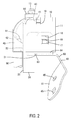
Fig. 2 is a side view showing a state in which the terminal platform is fixed to the bracket, and the terminal fitting is fixed to the terminal fixing portion. -
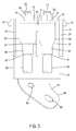
Fig. 3 is a rear view showing a state in which the terminal platform is fixed to the bracket, and the terminal fitting is fixed to the terminal fixing portion. -
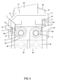
Fig. 4 is a plan view showing a state in which the terminal platform is fixed to the bracket, and the terminal fitting is fixed to the terminal fixing portion. -
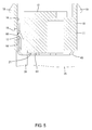
Fig. 5 is a cross-sectional view showing a structure by which the terminal platform is engaged to the bracket. -
Fig. 6 is a rear view of the terminal platform. -
Fig. 7 is a side view of the bracket. -
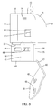
Fig. 8 is a side view showing a state in which erroneous assembly of the terminal platform to the bracket is restricted. -
Embodiment 1 is explained with reference toFigs. 1-8 . Aterminal platform 10 ofembodiment 1 is an example of a connecting terminal platform that relays a power line of an automobile. Theterminal platform 10 is supported by ametal bracket 60, and further,terminal fittings 40 are fixed to theterminal platform 10. Additionally, in the following explanation, with respect to front and rear directions, the right side ofFig. 1 is the front side. With respect to vertical directions,Fig. 1 is used as a reference. - The
bracket 60 is metal and is molded by bending a flat plate material as shown inFig. 7 . Thebracket 60 is constituted by abase plate portion 61 that is fixed to an installation surface of an undepicted vehicle, atransition portion 62 that connects to an upper end of thebase plate portion 61 and bends out from an upper end of thebase plate portion 61 at an obtuse angle, asupport portion 63 that connects to an upper end of thetransition portion 62 and bends out from the upper end of thetransition portion 62 at an obtuse angle, and a pair ofattachment portions 64 that are bent up from both side edges of thesupport portion 63 substantially at right angles. - The
base plate portion 61 is fixed to an installation surface of an undepicted vehicle by bolts, and has a plurality of through-holes 65 through which the bolts pass. In a state in which thebase plate portion 61 is fixed to a vehicle, thesupport portion 63 is arranged substantially horizontally along a front-to-rear direction. The twoattachment portions 64 are at positions shifted relative to each other in the front-to-rear direction at the two side edges of thesupport portion 63. One of theattachment portions 64 is positioned at a front end of one side edge of thesupport portion 63, and theother attachment portion 64 is positioned at an intermediate portion, in the front-to-rear direction, of the other side edge of thesupport portion 63. Additionally, substantiallyrectangular attachment holes 66 are provided in both of theattachment portions 64. - The
terminal fittings 40 are of metal plate material and are bent into a substantially L shape. As shown inFigs. 2-4 , in a state in which theterminal fittings 40 are fixed to theterminal platform 10, they have a terminalmain bodies 41 that are arranged substantially horizontally along the front-to-rear direction, andwire connection portions 42 that are bent downward from the terminalmain bodies 41 and are arranged substantially vertically along a vertical direction. Thewire connection portions 42 are connected by crimping towire cores 91 that are exposed at end portions ofwires 90. The terminalmain bodies 41 each have aconnection hole 43 through which passes astud bolt 13, described below (seeFig. 2 ). As shown inFig. 3 , a pair ofterminal fittings 40 is fixed to theterminal platform 10. - The
terminal platform 10 is of synthetic resin, and as shown inFig. 1 , is provided with a box-shaped platformmain body 11 and a cap-shaped cover 30 that covers the platformmain body 11. As shown inFig. 4 , at an upper surface of the platformmain body 11, there is provided aterminal fixing portion 12 for fixing the terminalmain body 41 of bothterminal fittings 40. As shown inFig. 6 ,stud bolts 13, which have a substantially cylindrical shape, and which form a pair in the width direction, are protrudingly arranged in theterminal fixing portion 12. Additionally, a strip-shaped connection terminal 14, inserted so as to span across bothstud bolts 13, is exposedly arranged in theterminal fixing portion 12. At an upper surface of the platformmain body 11, aperipheral wall 15 is protrudingly arranged, surrounding a periphery of theterminal fixing portion 12, excluding a rear end side at which thewire connection portions 42 are lead out (seeFig. 4 ). - Additionally, as shown in
Fig. 4 , in the platformmain body 11, there is provided a pair ofmounting holes 16 that pass through in a vertical direction, at positions shifted relative to each other in the front-to-rear direction at two width-direction sides, between which is theterminal fixing portion 12. Furthermore, a pair ofelastic locking arms 17 is provided on the platformmain body 11 so as to face the inside of bothmounting holes 16. As shown inFig. 5 , theelastic locking arms 17 extend diagonally upward in a cantilevered state from lower portions of the inside surfaces of themounting holes 16, and can bendingly deform about the lower portions of the inside surfaces of themounting holes 16 as a fulcrum. Theattachment portions 64 of thebracket 60 are inserted into themounting holes 16 from below, along inside surfaces of the mounting holes 16 (surfaces opposite to the surfaces at which theelastic locking arms 17 are connected). Leading end portions of theelastic locking arms 17 engage with theattachment holes 66 of theattachment portions 64, whereby the terminal platform 20 is locked to thebracket 60. - In outer surfaces at both sides of the platform
main body 11, there is provided a pair ofwindow holes 18 at positions facing the elastic locking arms 17 (seeFig. 5 ). As shown inFigs. 1 and5 , theelastic locking arms 17 can be viewed from the sides through thewindow holes 18. Additionally, as shown inFig. 6 , a pair oflock portions 19 is protrudingly provided at upper end portions of outer surfaces of both sides of the platformmain body 11. Later-describedlock arms 31 of thecover 30 are engageable with bothlock portions 19. - As shown in
Fig. 5 , at opening peripheries of the mountingholes 16 at a lower surface of the platformmain body 11, there is provided a pair of support-receivingportions 21 that can abut against, and are supported by, thesupport portion 63 of thebracket 60. The support-receivingportions 21 are flat surfaces that are opposite, in a vertical direction, to theterminal fixing portion 12. - As shown in
Fig. 6 , asurface portion 22 is provided at a rear surface of the platformmain body 11. Thesurface portion 22 is a flat surface that follows a direction perpendicular to surface directions of theterminal fixing portion 12 and the support-receivingportions 21, and is arranged so as to span from top to bottom from theterminal fixing portion 12 to the support-receivingportions 21. - As shown in
Fig. 3 ,wire connection portions 42 of bothterminal fittings 40 are arranged adjacent to each other, in the width direction, at thesurface 22. At a width-direction center portion of thesurface 22, there is provided apartition wall 23 that separates the twowire connection portions 42. Thepartition wall 23 is configured in a plate shape that extends in a vertical direction, and is arranged along a range that covers the entire crimp area of thewire connection portions 42. - At the end portions, in the width direction, of the
surface 22, there is provided a pair ofprotection walls 24, at sides between which thewire connection portions 42 of the twoterminal fittings 40 are interposed. Bothprotection walls 24 are configured in a plate shape that extends in a vertical direction. Lower ends of theprotection walls 24 are arranged at the same height position as a lower end of thepartition wall 23. Thewire connection portions 42 of bothterminal fittings 40 are covered and hidden from the side directions by theprotection walls 24. - Additionally, the
terminal platform 10 is provided with apartition wall 25 that extends downward from a lower end of the platformmain body 11. Thepartition wall 25 has a flat plate configuration that connects coplanarly to thesurface 22 and extends across an entire width of the platformmain body 11. Additionally, thepartition wall 25 is arranged along a range that covers the end portions of thewires 90. As shown inFig. 2 , thepartition wall 25 is arranged facing the tip end of thesupport portion 63 of thebracket 60, in a front-to-rear direction. Additionally, as shown inFig. 5 , at a front surface of thepartition wall 25, there is provided a plate-shapedprotruding piece 26 that extends to the support-receivingportions 21. The protrudingpiece 26 is configured to extend substantially perpendicularly to the front surface of thepartition wall 25. - The
cover 30 is mounted to the platformmain body 11 from above, so as to cover bothterminal fittings 40 and thewires 90. The pair oflock arms 31, which extend out in a downward direction from outer surfaces of both sides of thecover 30, are elastically engaged by the twolock portions 19, whereby thecover 30 is lockedly held to the platform main body 11 (seeFig. 1 ). In a state in which thecover 30 is correctly mounted to the platformmain body 11, the outer sides of the twoprotection walls 24 are covered by twoside walls 32 of thecover 30. On an inner surface of thecover 30, undepicted partition plates are provided that separate the terminalmain bodies 41 of the twoterminal fittings 40. - Next, a method of assembling the
terminal fittings 40 to theterminal platform 10 ofembodiment 1, and operational effects, will be described. - First, the
base plate portion 61 of thebracket 60 is fastened by bolts to an installation surface of an undepicted vehicle, and thebracket 60 is attached and fixed to the vehicle. Next, theterminal platform 10 is placed on thesupport portion 63 of thebracket 60. In so doing, the twoattachment portions 64 of thebracket 60 are inserted into corresponding attachment holes 66 and elastically engaged with the elastic lockingarms 17, the twoattachment portions 64 of thebracket 60 are inserted into the mountingholes 16 of the platformmain body 11, and the elastic lockingarms 17 are inserted into, and elastically engaged with, the corresponding attachment holes 66 of theattachment portions 64, and theterminal platform 10 is mounted and fixed to thebracket 60. At this time, because thepartition wall 25 is between (i) thewire connection portions 42 of theterminal fittings 40 and (ii) thesupport portion 63, there is no electrical contact between thewire connection portions 42 and thesupport portion 63. - On the other hand, as shown in
Fig. 8 , if it is attempted to assemble theterminal platform 10 to thebracket 60 in an erroneous assembly orientation in which the front and rear of theterminal platform 10 are reversed, the lower end of thepartition wall 25 abuts against the upper surface of thesupport portion 63 of thebracket 60, and assembly beyond that point is restricted. Therefore, theterminal platform 10 is not assembled to thebracket 60 in an erroneous assembly orientation. - After the
terminal platform 10 has been assembled to thebracket 60, the terminalmain bodies 41 of the twoterminal fittings 40 are fixed to theterminal fixing portion 12 of the platformmain body 11. At this time, thestud bolts 13 are passed through the connection holes 43 of the terminalmain bodies 41, and as shown inFig. 3 , by fastening fixingmembers 50 such as nuts or the like to thestud bolts 13, the terminalmain bodies 41 are fixed to theterminal fixing portion 12 of the platformmain body 11. At the time of fastening the fixingmembers 50, theterminal fixing portion 12 is pressed, and a downward fixing force acts on the platformmain body 11, but because the support-receivingportions 21 of the platformmain body 11 are supported by thesupport portion 63 of thebracket 60 at positions opposing the direction in which the fixing force acts, theterminal platform 10 does not fall off from thebracket 60. Along with the fixing of the twoterminal fittings 40 to thestud bolts 13 through the fixingmembers 50, the twoterminal fittings 40 are connected to theconnection terminal 14 that is inserted into theterminal fixing portion 12, and the twoterminal fittings 40 are short-circuited to each other and connected through theconnection terminal 14. Finally, thecover 30 is put on the platformmain body 11, and the periphery of bothterminal fittings 40 and theconnection terminal 14 is covered and protected by thecover 30. - As described above, according to
embodiment 1, because theterminal fixing portion 12 of the platformmain body 11 is positioned at a side opposite to the support-receivingportions 21 that are supported by thesupport portion 63 of thebracket 60, the fixing force that acts on theterminal fixing portion 12 in connection with the fastening of the fixingmembers 50 is directly received by thesupport portion 63 through the support-receivingportions 21. Therefore, theterminal platform 10 is stably supported by thebracket 60. - Additionally, even though the tip ends of the
support portion 63 are arranged at positions near thewire connection portions 42 of theterminal fittings 40, thepartition wall 25 of theterminal platform 10 separates the tip ends of thesupport portion 63 from thewire connection portions 42, whereby electrical contact between thebracket 60 and theterminal fittings 40 is avoided. Therefore, electrical conduction reliability of thewire connection portions 42 is ensured. - Additionally, because the
partition wall 23 provided on thesurface 22 of the platformmain body 11 separates thewire connection portions 42 of the twoterminal fittings 40 that are adjacent in the width direction, electrical contact between the twoterminal fittings 40 is also avoided. - Furthermore, if the
terminal platform 10 is in an erroneous assembly orientation with respect to thebracket 60, the lower end of thepartition wall 25 abuts against thesupport portion 63 of thebracket 60, and assembly beyond that point is restricted. Therefore, a condition of assembling theterminal platform 10 to thebracket 60 in an erroneous assembly orientation is avoided. Furthermore, because a structure that suppresses erroneous assembly is constituted by thepartition wall 25, a special structure for suppressing erroneous assembly is not needed, and the overall structure can be simplified. - This invention is not limited to the embodiment described in the foregoing descriptions and the drawings. For example, modes such as the following are also included within the technical scope of this invention.
- (1) A structure is also acceptable in which no connection terminal is provided in the terminal platform. For example, the terminal fitting may be constituted as battery terminal, and the terminal platform may comprise the battery housing.
- (2) The support-receiving portions may be constituted by the entire lower surface of the platform main body.
- (3) As long as the partition wall faces the tip ends of the support portions and separates the support portions from the wire connection portions, its shape is arbitrary. For example, the partition wall may be divided into two partition walls, one provided for each of the two terminal fittings.
- (4) As long as the bracket has a support portion that supports a support-receiving portion of the terminal platform, its shape is arbitrary. For example, the transition portion of the bracket may be omitted, and the bracket may have a configuration that is bent into a substantially L shape with the support portion and the base plate portion.
-
- 10
- Terminal platform
- 11
- Platform main body
- 12
- Terminal fixing portion
- 21
- Support-receiving portions
- 22
- Surface
- 23
- Partition wall
- 25
- Partition wall
- 40
- Terminal fittings
- 41
- Terminal main bodies
- 42
- Wire connection portions
- 60
- Bracket
- 63
- Support portion
- 90
- Wires
Claims (6)
- A resin terminal platform (10) that supports a terminal fitting (40) having (i) a wire connection portion (42) to be connected to a wire (90) and (ii) a terminal main body (41) that extends in a direction intersecting the wire connection portion (42), the resin terminal platform (10) comprising:a platform main body (11) including:(i) a support-receiving portion (21) that is supported by a support portion (63) formed on a metal bracket (60),(ii) a terminal fixing portion (12) that is positioned at a side opposite to the support-receiving portion (21) and fixes the terminal main body (41) of the terminal fitting (40), and(iii) a surface portion (22) that is arranged at a side intersecting the terminal fixing portion (12) and the support-receiving portion (21), and that extends along the wire connection portion (42) of the terminal fitting (40), anda first partition wall (25) that extends to the surface portion (22) of the platform main body (11) and is arranged facing a tip end of the support portion (63).
- The terminal platform (10) of claim 1, wherein the terminal fixing portion (12) includes a plurality of terminal fixing portions (12) and the terminal platform (10) supports the plurality of terminal fixing portions (12), and
a second partition wall (23) that separates the wire connection portions (42), which are adjacent in a width direction, is provided on the surface portion (22) of the platform main body (11). - The terminal platform (10) of claim 1 or 2, wherein the first partition wall (25) is configured to extend out from the platform main body (11), and a tip end of the first partition wall (25) abuts against the support portion (63) of the bracket (60) to discourage incorrect assembly under the condition that the terminal platform and (10) the bracket (60) are assembled in a reversed orientation that is opposite to a normal orientation.
- A resin terminal platform (10) that supports a terminal fitting (40) having (i) a wire connection portion (42) to be connected to a wire (90) and (ii) a terminal main body (41) that extends in a direction intersecting the wire connection portion (42), the terminal platform (10) comprising:a platform main body (11);a metal bracket (60) on the platform main body (11);a support portion (63) formed on the metal bracket (60);a support-receiving portion (21) that is supported by the support portion (63);a terminal fixing portion (12) that is positioned on the platform main body (11) at a side opposite to the support-receiving portion (21) and fixes the terminal main body (41) of the terminal fitting (40) into place;a surface portion (22) that is arranged on the platform main body (11) at a side intersecting the terminal fixing portion (12) and the support-receiving portion (21), and that extends along the wire connection portion (42) of the terminal fitting (40); anda first partition wall (25) that extends between (i) the wire connection portion (42) of the terminal fitting (40) and (ii) the support portion (63).
- The terminal platform (10) of claim 4, wherein the terminal fixing portion (12) includes a plurality of terminal fixing portions (12) and the terminal platform supports the plurality of terminal fixing portions (12), and
a second partition wall (23) that separates the wire connection portions (42), which are adjacent in a width direction, is provided on the surface portion (22) of the platform main body (11). - The terminal platform (10) of claim 4 or 5, wherein the first partition wall (25) is configured to extend out from the platform main body (11), and a tip end of the first partition wall (25) abuts against the support portion (63) of the bracket (60) to discourage incorrect assembly under the condition that the terminal platform and the bracket (60) are assembled in a reversed orientation that is opposite to a normal orientation.
Applications Claiming Priority (1)
| Application Number | Priority Date | Filing Date | Title |
|---|---|---|---|
| JP2013019586A JP2014150033A (en) | 2013-02-04 | 2013-02-04 | Terminal Block |
Publications (2)
| Publication Number | Publication Date |
|---|---|
| EP2763258A1 true EP2763258A1 (en) | 2014-08-06 |
| EP2763258B1 EP2763258B1 (en) | 2015-06-24 |
Family
ID=49989559
Family Applications (1)
| Application Number | Title | Priority Date | Filing Date |
|---|---|---|---|
| EP14151852.2A Active EP2763258B1 (en) | 2013-02-04 | 2014-01-21 | Terminal platform |
Country Status (3)
| Country | Link |
|---|---|
| US (1) | US9093829B2 (en) |
| EP (1) | EP2763258B1 (en) |
| JP (1) | JP2014150033A (en) |
Citations (4)
| Publication number | Priority date | Publication date | Assignee | Title |
|---|---|---|---|---|
| DE19803141A1 (en) * | 1998-01-28 | 1999-07-29 | Wemefa Horst Christopeit Gmbh | Springy claw |
| JP2009170357A (en) * | 2008-01-18 | 2009-07-30 | Yazaki Corp | Terminal fixing structure and electrical junction box having this terminal fixing structure |
| US20100261365A1 (en) * | 2009-04-13 | 2010-10-14 | Sumitomo Wiring Systems, Ltd. | Connector |
| WO2011070993A1 (en) * | 2009-12-10 | 2011-06-16 | Yazaki Corporation | Connector assembly |
Family Cites Families (5)
| Publication number | Priority date | Publication date | Assignee | Title |
|---|---|---|---|---|
| US6322376B1 (en) * | 2000-03-31 | 2001-11-27 | Yazaki North America | Stud bolt holder for a power distribution box |
| US6875052B1 (en) * | 2003-09-30 | 2005-04-05 | Zippy Technology Corp. | Remainder electric power distributing device of a computer |
| JP5074782B2 (en) * | 2007-02-15 | 2012-11-14 | 矢崎総業株式会社 | Electrical junction box |
| JP2008269981A (en) | 2007-04-20 | 2008-11-06 | Osada:Kk | Feed-through terminal block, and terminal metal fitting used for the same |
| US7762852B2 (en) * | 2008-02-28 | 2010-07-27 | Btx Technologies, Inc. | D-subminiature connector assemblies and a housing therefore |
-
2013
- 2013-02-04 JP JP2013019586A patent/JP2014150033A/en active Pending
-
2014
- 2014-01-17 US US14/158,070 patent/US9093829B2/en active Active
- 2014-01-21 EP EP14151852.2A patent/EP2763258B1/en active Active
Patent Citations (4)
| Publication number | Priority date | Publication date | Assignee | Title |
|---|---|---|---|---|
| DE19803141A1 (en) * | 1998-01-28 | 1999-07-29 | Wemefa Horst Christopeit Gmbh | Springy claw |
| JP2009170357A (en) * | 2008-01-18 | 2009-07-30 | Yazaki Corp | Terminal fixing structure and electrical junction box having this terminal fixing structure |
| US20100261365A1 (en) * | 2009-04-13 | 2010-10-14 | Sumitomo Wiring Systems, Ltd. | Connector |
| WO2011070993A1 (en) * | 2009-12-10 | 2011-06-16 | Yazaki Corporation | Connector assembly |
Also Published As
| Publication number | Publication date |
|---|---|
| US20140220832A1 (en) | 2014-08-07 |
| JP2014150033A (en) | 2014-08-21 |
| EP2763258B1 (en) | 2015-06-24 |
| US9093829B2 (en) | 2015-07-28 |
Similar Documents
| Publication | Publication Date | Title |
|---|---|---|
| JP5166943B2 (en) | Busbar assembly structure | |
| EP2432091B1 (en) | Bracket structure of electrical connection box | |
| JP4916955B2 (en) | Electronic component built-in unit | |
| US7364438B2 (en) | Electrical connection box | |
| JP5547546B2 (en) | Assembly structure of electrical junction box | |
| JP6183701B2 (en) | Directly attached battery fusible link | |
| US8383934B2 (en) | Electrical junction box | |
| CN106100569B (en) | Terminal box and solar battery module | |
| US9972823B2 (en) | Fusible link | |
| JP2012222851A (en) | Bracket structure for holding washer | |
| JP6021481B2 (en) | Fixing structure between fuse holder and fuse cover | |
| JP2016096674A (en) | Electrical junction box | |
| JP2015042109A (en) | Terminal board | |
| EP2763258B1 (en) | Terminal platform | |
| JP6238873B2 (en) | Electrical junction box | |
| US8231404B2 (en) | Electronic connection box | |
| KR102209626B1 (en) | Multi-contact plug with integrated shorting jumper element | |
| JP5737049B2 (en) | Electrical connection member | |
| KR101439144B1 (en) | Alarm Structure of Fuse Box Cover For Unsuitable Combination | |
| JP2024143310A (en) | Electrical Junction Box | |
| JP2022029752A (en) | Fuse unit | |
| JP2013078215A (en) | Battery pack | |
| WO2014203760A1 (en) | Terminal fitting | |
| JP2015011866A (en) | Battery terminal | |
| CN114759507A (en) | Electrical connection box |
Legal Events
| Date | Code | Title | Description |
|---|---|---|---|
| PUAI | Public reference made under article 153(3) epc to a published international application that has entered the european phase |
Free format text: ORIGINAL CODE: 0009012 |
|
| 17P | Request for examination filed |
Effective date: 20140121 |
|
| AK | Designated contracting states |
Kind code of ref document: A1 Designated state(s): AL AT BE BG CH CY CZ DE DK EE ES FI FR GB GR HR HU IE IS IT LI LT LU LV MC MK MT NL NO PL PT RO RS SE SI SK SM TR |
|
| AX | Request for extension of the european patent |
Extension state: BA ME |
|
| R17P | Request for examination filed (corrected) |
Effective date: 20141208 |
|
| RBV | Designated contracting states (corrected) |
Designated state(s): AL AT BE BG CH CY CZ DE DK EE ES FI FR GB GR HR HU IE IS IT LI LT LU LV MC MK MT NL NO PL PT RO RS SE SI SK SM TR |
|
| REG | Reference to a national code |
Ref country code: DE Ref legal event code: R079 Ref document number: 602014000049 Country of ref document: DE Free format text: PREVIOUS MAIN CLASS: H02G0015020000 Ipc: H01R0009160000 |
|
| GRAP | Despatch of communication of intention to grant a patent |
Free format text: ORIGINAL CODE: EPIDOSNIGR1 |
|
| RIC1 | Information provided on ipc code assigned before grant |
Ipc: H02G 3/30 20060101ALI20150218BHEP Ipc: H02G 15/02 20060101ALI20150218BHEP Ipc: H01R 9/16 20060101AFI20150218BHEP |
|
| INTG | Intention to grant announced |
Effective date: 20150312 |
|
| GRAS | Grant fee paid |
Free format text: ORIGINAL CODE: EPIDOSNIGR3 |
|
| GRAA | (expected) grant |
Free format text: ORIGINAL CODE: 0009210 |
|
| AK | Designated contracting states |
Kind code of ref document: B1 Designated state(s): AL AT BE BG CH CY CZ DE DK EE ES FI FR GB GR HR HU IE IS IT LI LT LU LV MC MK MT NL NO PL PT RO RS SE SI SK SM TR |
|
| REG | Reference to a national code |
Ref country code: GB Ref legal event code: FG4D |
|
| REG | Reference to a national code |
Ref country code: CH Ref legal event code: EP |
|
| REG | Reference to a national code |
Ref country code: AT Ref legal event code: REF Ref document number: 733273 Country of ref document: AT Kind code of ref document: T Effective date: 20150715 |
|
| REG | Reference to a national code |
Ref country code: IE Ref legal event code: FG4D |
|
| REG | Reference to a national code |
Ref country code: DE Ref legal event code: R096 Ref document number: 602014000049 Country of ref document: DE |
|
| PG25 | Lapsed in a contracting state [announced via postgrant information from national office to epo] |
Ref country code: FI Free format text: LAPSE BECAUSE OF FAILURE TO SUBMIT A TRANSLATION OF THE DESCRIPTION OR TO PAY THE FEE WITHIN THE PRESCRIBED TIME-LIMIT Effective date: 20150624 Ref country code: LT Free format text: LAPSE BECAUSE OF FAILURE TO SUBMIT A TRANSLATION OF THE DESCRIPTION OR TO PAY THE FEE WITHIN THE PRESCRIBED TIME-LIMIT Effective date: 20150624 Ref country code: NO Free format text: LAPSE BECAUSE OF FAILURE TO SUBMIT A TRANSLATION OF THE DESCRIPTION OR TO PAY THE FEE WITHIN THE PRESCRIBED TIME-LIMIT Effective date: 20150924 Ref country code: HR Free format text: LAPSE BECAUSE OF FAILURE TO SUBMIT A TRANSLATION OF THE DESCRIPTION OR TO PAY THE FEE WITHIN THE PRESCRIBED TIME-LIMIT Effective date: 20150624 |
|
| REG | Reference to a national code |
Ref country code: AT Ref legal event code: MK05 Ref document number: 733273 Country of ref document: AT Kind code of ref document: T Effective date: 20150624 |
|
| REG | Reference to a national code |
Ref country code: LT Ref legal event code: MG4D |
|
| PG25 | Lapsed in a contracting state [announced via postgrant information from national office to epo] |
Ref country code: GR Free format text: LAPSE BECAUSE OF FAILURE TO SUBMIT A TRANSLATION OF THE DESCRIPTION OR TO PAY THE FEE WITHIN THE PRESCRIBED TIME-LIMIT Effective date: 20150925 Ref country code: BG Free format text: LAPSE BECAUSE OF FAILURE TO SUBMIT A TRANSLATION OF THE DESCRIPTION OR TO PAY THE FEE WITHIN THE PRESCRIBED TIME-LIMIT Effective date: 20150924 Ref country code: LV Free format text: LAPSE BECAUSE OF FAILURE TO SUBMIT A TRANSLATION OF THE DESCRIPTION OR TO PAY THE FEE WITHIN THE PRESCRIBED TIME-LIMIT Effective date: 20150624 Ref country code: RS Free format text: LAPSE BECAUSE OF FAILURE TO SUBMIT A TRANSLATION OF THE DESCRIPTION OR TO PAY THE FEE WITHIN THE PRESCRIBED TIME-LIMIT Effective date: 20150624 |
|
| REG | Reference to a national code |
Ref country code: NL Ref legal event code: MP Effective date: 20150624 |
|
| REG | Reference to a national code |
Ref country code: FR Ref legal event code: PLFP Year of fee payment: 3 |
|
| PG25 | Lapsed in a contracting state [announced via postgrant information from national office to epo] |
Ref country code: EE Free format text: LAPSE BECAUSE OF FAILURE TO SUBMIT A TRANSLATION OF THE DESCRIPTION OR TO PAY THE FEE WITHIN THE PRESCRIBED TIME-LIMIT Effective date: 20150624 |
|
| PG25 | Lapsed in a contracting state [announced via postgrant information from national office to epo] |
Ref country code: PT Free format text: LAPSE BECAUSE OF FAILURE TO SUBMIT A TRANSLATION OF THE DESCRIPTION OR TO PAY THE FEE WITHIN THE PRESCRIBED TIME-LIMIT Effective date: 20151026 Ref country code: IS Free format text: LAPSE BECAUSE OF FAILURE TO SUBMIT A TRANSLATION OF THE DESCRIPTION OR TO PAY THE FEE WITHIN THE PRESCRIBED TIME-LIMIT Effective date: 20151024 Ref country code: SK Free format text: LAPSE BECAUSE OF FAILURE TO SUBMIT A TRANSLATION OF THE DESCRIPTION OR TO PAY THE FEE WITHIN THE PRESCRIBED TIME-LIMIT Effective date: 20150624 Ref country code: ES Free format text: LAPSE BECAUSE OF FAILURE TO SUBMIT A TRANSLATION OF THE DESCRIPTION OR TO PAY THE FEE WITHIN THE PRESCRIBED TIME-LIMIT Effective date: 20150624 Ref country code: RO Free format text: LAPSE BECAUSE OF NON-PAYMENT OF DUE FEES Effective date: 20150624 Ref country code: CZ Free format text: LAPSE BECAUSE OF FAILURE TO SUBMIT A TRANSLATION OF THE DESCRIPTION OR TO PAY THE FEE WITHIN THE PRESCRIBED TIME-LIMIT Effective date: 20150624 Ref country code: PL Free format text: LAPSE BECAUSE OF FAILURE TO SUBMIT A TRANSLATION OF THE DESCRIPTION OR TO PAY THE FEE WITHIN THE PRESCRIBED TIME-LIMIT Effective date: 20150624 Ref country code: AT Free format text: LAPSE BECAUSE OF FAILURE TO SUBMIT A TRANSLATION OF THE DESCRIPTION OR TO PAY THE FEE WITHIN THE PRESCRIBED TIME-LIMIT Effective date: 20150624 |
|
| REG | Reference to a national code |
Ref country code: DE Ref legal event code: R097 Ref document number: 602014000049 Country of ref document: DE |
|
| PG25 | Lapsed in a contracting state [announced via postgrant information from national office to epo] |
Ref country code: DK Free format text: LAPSE BECAUSE OF FAILURE TO SUBMIT A TRANSLATION OF THE DESCRIPTION OR TO PAY THE FEE WITHIN THE PRESCRIBED TIME-LIMIT Effective date: 20150624 Ref country code: IT Free format text: LAPSE BECAUSE OF FAILURE TO SUBMIT A TRANSLATION OF THE DESCRIPTION OR TO PAY THE FEE WITHIN THE PRESCRIBED TIME-LIMIT Effective date: 20150624 |
|
| PLBE | No opposition filed within time limit |
Free format text: ORIGINAL CODE: 0009261 |
|
| STAA | Information on the status of an ep patent application or granted ep patent |
Free format text: STATUS: NO OPPOSITION FILED WITHIN TIME LIMIT |
|
| PG25 | Lapsed in a contracting state [announced via postgrant information from national office to epo] |
Ref country code: BE Free format text: LAPSE BECAUSE OF NON-PAYMENT OF DUE FEES Effective date: 20160131 |
|
| 26N | No opposition filed |
Effective date: 20160329 |
|
| PG25 | Lapsed in a contracting state [announced via postgrant information from national office to epo] |
Ref country code: SI Free format text: LAPSE BECAUSE OF FAILURE TO SUBMIT A TRANSLATION OF THE DESCRIPTION OR TO PAY THE FEE WITHIN THE PRESCRIBED TIME-LIMIT Effective date: 20150624 Ref country code: LU Free format text: LAPSE BECAUSE OF FAILURE TO SUBMIT A TRANSLATION OF THE DESCRIPTION OR TO PAY THE FEE WITHIN THE PRESCRIBED TIME-LIMIT Effective date: 20160121 |
|
| PG25 | Lapsed in a contracting state [announced via postgrant information from national office to epo] |
Ref country code: MC Free format text: LAPSE BECAUSE OF FAILURE TO SUBMIT A TRANSLATION OF THE DESCRIPTION OR TO PAY THE FEE WITHIN THE PRESCRIBED TIME-LIMIT Effective date: 20150624 |
|
| REG | Reference to a national code |
Ref country code: IE Ref legal event code: MM4A |
|
| REG | Reference to a national code |
Ref country code: FR Ref legal event code: PLFP Year of fee payment: 4 |
|
| PG25 | Lapsed in a contracting state [announced via postgrant information from national office to epo] |
Ref country code: BE Free format text: LAPSE BECAUSE OF FAILURE TO SUBMIT A TRANSLATION OF THE DESCRIPTION OR TO PAY THE FEE WITHIN THE PRESCRIBED TIME-LIMIT Effective date: 20150624 |
|
| PG25 | Lapsed in a contracting state [announced via postgrant information from national office to epo] |
Ref country code: IE Free format text: LAPSE BECAUSE OF NON-PAYMENT OF DUE FEES Effective date: 20160121 |
|
| PG25 | Lapsed in a contracting state [announced via postgrant information from national office to epo] |
Ref country code: SE Free format text: LAPSE BECAUSE OF FAILURE TO SUBMIT A TRANSLATION OF THE DESCRIPTION OR TO PAY THE FEE WITHIN THE PRESCRIBED TIME-LIMIT Effective date: 20150624 Ref country code: NL Free format text: LAPSE BECAUSE OF FAILURE TO SUBMIT A TRANSLATION OF THE DESCRIPTION OR TO PAY THE FEE WITHIN THE PRESCRIBED TIME-LIMIT Effective date: 20150624 |
|
| PG25 | Lapsed in a contracting state [announced via postgrant information from national office to epo] |
Ref country code: MT Free format text: LAPSE BECAUSE OF FAILURE TO SUBMIT A TRANSLATION OF THE DESCRIPTION OR TO PAY THE FEE WITHIN THE PRESCRIBED TIME-LIMIT Effective date: 20150624 |
|
| REG | Reference to a national code |
Ref country code: CH Ref legal event code: PL |
|
| PG25 | Lapsed in a contracting state [announced via postgrant information from national office to epo] |
Ref country code: CH Free format text: LAPSE BECAUSE OF NON-PAYMENT OF DUE FEES Effective date: 20170131 Ref country code: LI Free format text: LAPSE BECAUSE OF NON-PAYMENT OF DUE FEES Effective date: 20170131 |
|
| REG | Reference to a national code |
Ref country code: FR Ref legal event code: PLFP Year of fee payment: 5 |
|
| PG25 | Lapsed in a contracting state [announced via postgrant information from national office to epo] |
Ref country code: CY Free format text: LAPSE BECAUSE OF FAILURE TO SUBMIT A TRANSLATION OF THE DESCRIPTION OR TO PAY THE FEE WITHIN THE PRESCRIBED TIME-LIMIT Effective date: 20150624 Ref country code: HU Free format text: LAPSE BECAUSE OF FAILURE TO SUBMIT A TRANSLATION OF THE DESCRIPTION OR TO PAY THE FEE WITHIN THE PRESCRIBED TIME-LIMIT; INVALID AB INITIO Effective date: 20140121 Ref country code: SM Free format text: LAPSE BECAUSE OF FAILURE TO SUBMIT A TRANSLATION OF THE DESCRIPTION OR TO PAY THE FEE WITHIN THE PRESCRIBED TIME-LIMIT Effective date: 20150624 |
|
| PG25 | Lapsed in a contracting state [announced via postgrant information from national office to epo] |
Ref country code: TR Free format text: LAPSE BECAUSE OF FAILURE TO SUBMIT A TRANSLATION OF THE DESCRIPTION OR TO PAY THE FEE WITHIN THE PRESCRIBED TIME-LIMIT Effective date: 20150624 Ref country code: MK Free format text: LAPSE BECAUSE OF FAILURE TO SUBMIT A TRANSLATION OF THE DESCRIPTION OR TO PAY THE FEE WITHIN THE PRESCRIBED TIME-LIMIT Effective date: 20150624 Ref country code: MT Free format text: LAPSE BECAUSE OF FAILURE TO SUBMIT A TRANSLATION OF THE DESCRIPTION OR TO PAY THE FEE WITHIN THE PRESCRIBED TIME-LIMIT Effective date: 20160131 |
|
| GBPC | Gb: european patent ceased through non-payment of renewal fee |
Effective date: 20180121 |
|
| PG25 | Lapsed in a contracting state [announced via postgrant information from national office to epo] |
Ref country code: AL Free format text: LAPSE BECAUSE OF FAILURE TO SUBMIT A TRANSLATION OF THE DESCRIPTION OR TO PAY THE FEE WITHIN THE PRESCRIBED TIME-LIMIT Effective date: 20150624 |
|
| PG25 | Lapsed in a contracting state [announced via postgrant information from national office to epo] |
Ref country code: GB Free format text: LAPSE BECAUSE OF NON-PAYMENT OF DUE FEES Effective date: 20180121 |
|
| REG | Reference to a national code |
Ref country code: DE Ref legal event code: R084 Ref document number: 602014000049 Country of ref document: DE |
|
| PGFP | Annual fee paid to national office [announced via postgrant information from national office to epo] |
Ref country code: DE Payment date: 20211130 Year of fee payment: 9 |
|
| P01 | Opt-out of the competence of the unified patent court (upc) registered |
Effective date: 20230517 |
|
| REG | Reference to a national code |
Ref country code: DE Ref legal event code: R119 Ref document number: 602014000049 Country of ref document: DE |
|
| PG25 | Lapsed in a contracting state [announced via postgrant information from national office to epo] |
Ref country code: DE Free format text: LAPSE BECAUSE OF NON-PAYMENT OF DUE FEES Effective date: 20230801 |
|
| PGFP | Annual fee paid to national office [announced via postgrant information from national office to epo] |
Ref country code: FR Payment date: 20251128 Year of fee payment: 13 |