EP2763209A1 - Rechargeable battery - Google Patents
Rechargeable battery Download PDFInfo
- Publication number
- EP2763209A1 EP2763209A1 EP14153032.9A EP14153032A EP2763209A1 EP 2763209 A1 EP2763209 A1 EP 2763209A1 EP 14153032 A EP14153032 A EP 14153032A EP 2763209 A1 EP2763209 A1 EP 2763209A1
- Authority
- EP
- European Patent Office
- Prior art keywords
- vent
- rechargeable battery
- cap plate
- depth
- electrode
- Prior art date
- Legal status (The legal status is an assumption and is not a legal conclusion. Google has not performed a legal analysis and makes no representation as to the accuracy of the status listed.)
- Granted
Links
Images




Classifications
-
- H—ELECTRICITY
- H01—ELECTRIC ELEMENTS
- H01M—PROCESSES OR MEANS, e.g. BATTERIES, FOR THE DIRECT CONVERSION OF CHEMICAL ENERGY INTO ELECTRICAL ENERGY
- H01M50/00—Constructional details or processes of manufacture of the non-active parts of electrochemical cells other than fuel cells, e.g. hybrid cells
- H01M50/30—Arrangements for facilitating escape of gases
-
- H—ELECTRICITY
- H01—ELECTRIC ELEMENTS
- H01M—PROCESSES OR MEANS, e.g. BATTERIES, FOR THE DIRECT CONVERSION OF CHEMICAL ENERGY INTO ELECTRICAL ENERGY
- H01M10/00—Secondary cells; Manufacture thereof
- H01M10/02—Details
-
- H—ELECTRICITY
- H01—ELECTRIC ELEMENTS
- H01M—PROCESSES OR MEANS, e.g. BATTERIES, FOR THE DIRECT CONVERSION OF CHEMICAL ENERGY INTO ELECTRICAL ENERGY
- H01M10/00—Secondary cells; Manufacture thereof
- H01M10/04—Construction or manufacture in general
- H01M10/0431—Cells with wound or folded electrodes
-
- H—ELECTRICITY
- H01—ELECTRIC ELEMENTS
- H01M—PROCESSES OR MEANS, e.g. BATTERIES, FOR THE DIRECT CONVERSION OF CHEMICAL ENERGY INTO ELECTRICAL ENERGY
- H01M50/00—Constructional details or processes of manufacture of the non-active parts of electrochemical cells other than fuel cells, e.g. hybrid cells
- H01M50/10—Primary casings; Jackets or wrappings
- H01M50/102—Primary casings; Jackets or wrappings characterised by their shape or physical structure
- H01M50/103—Primary casings; Jackets or wrappings characterised by their shape or physical structure prismatic or rectangular
-
- H—ELECTRICITY
- H01—ELECTRIC ELEMENTS
- H01M—PROCESSES OR MEANS, e.g. BATTERIES, FOR THE DIRECT CONVERSION OF CHEMICAL ENERGY INTO ELECTRICAL ENERGY
- H01M50/00—Constructional details or processes of manufacture of the non-active parts of electrochemical cells other than fuel cells, e.g. hybrid cells
- H01M50/10—Primary casings; Jackets or wrappings
- H01M50/147—Lids or covers
-
- H—ELECTRICITY
- H01—ELECTRIC ELEMENTS
- H01M—PROCESSES OR MEANS, e.g. BATTERIES, FOR THE DIRECT CONVERSION OF CHEMICAL ENERGY INTO ELECTRICAL ENERGY
- H01M50/00—Constructional details or processes of manufacture of the non-active parts of electrochemical cells other than fuel cells, e.g. hybrid cells
- H01M50/10—Primary casings; Jackets or wrappings
- H01M50/147—Lids or covers
- H01M50/148—Lids or covers characterised by their shape
- H01M50/15—Lids or covers characterised by their shape for prismatic or rectangular cells
-
- H—ELECTRICITY
- H01—ELECTRIC ELEMENTS
- H01M—PROCESSES OR MEANS, e.g. BATTERIES, FOR THE DIRECT CONVERSION OF CHEMICAL ENERGY INTO ELECTRICAL ENERGY
- H01M50/00—Constructional details or processes of manufacture of the non-active parts of electrochemical cells other than fuel cells, e.g. hybrid cells
- H01M50/30—Arrangements for facilitating escape of gases
- H01M50/342—Non-re-sealable arrangements
- H01M50/3425—Non-re-sealable arrangements in the form of rupturable membranes or weakened parts, e.g. pierced with the aid of a sharp member
-
- Y—GENERAL TAGGING OF NEW TECHNOLOGICAL DEVELOPMENTS; GENERAL TAGGING OF CROSS-SECTIONAL TECHNOLOGIES SPANNING OVER SEVERAL SECTIONS OF THE IPC; TECHNICAL SUBJECTS COVERED BY FORMER USPC CROSS-REFERENCE ART COLLECTIONS [XRACs] AND DIGESTS
- Y02—TECHNOLOGIES OR APPLICATIONS FOR MITIGATION OR ADAPTATION AGAINST CLIMATE CHANGE
- Y02E—REDUCTION OF GREENHOUSE GAS [GHG] EMISSIONS, RELATED TO ENERGY GENERATION, TRANSMISSION OR DISTRIBUTION
- Y02E60/00—Enabling technologies; Technologies with a potential or indirect contribution to GHG emissions mitigation
- Y02E60/10—Energy storage using batteries
-
- Y—GENERAL TAGGING OF NEW TECHNOLOGICAL DEVELOPMENTS; GENERAL TAGGING OF CROSS-SECTIONAL TECHNOLOGIES SPANNING OVER SEVERAL SECTIONS OF THE IPC; TECHNICAL SUBJECTS COVERED BY FORMER USPC CROSS-REFERENCE ART COLLECTIONS [XRACs] AND DIGESTS
- Y02—TECHNOLOGIES OR APPLICATIONS FOR MITIGATION OR ADAPTATION AGAINST CLIMATE CHANGE
- Y02P—CLIMATE CHANGE MITIGATION TECHNOLOGIES IN THE PRODUCTION OR PROCESSING OF GOODS
- Y02P70/00—Climate change mitigation technologies in the production process for final industrial or consumer products
- Y02P70/50—Manufacturing or production processes characterised by the final manufactured product
Definitions
- Embodiments relate to a rechargeable battery.
- Secondary batteries can be charged or discharged, unlike primary batteries, which cannot be charged. Therefore, secondary batteries, i.e. rechargeable batteries are widely used in the field of compact, up-to-date electronic equipment such as mobile phones, personal digital assistants (PDAs), and laptop computers.
- PDAs personal digital assistants
- the invention proposes the secondary battery of claim 1.
- Embodiments are specified in the dependent claims and are directed to a rechargeable battery including an electrode assembly including a first electrode plate, a second electrode plate, and a separator between the first electrode plate and the second electrode plate, a can having an opening at one side thereof through which the electrode assembly is inserted, the electrode assembly being accommodated in the inside of the can, and a cap plate that seals the opening of the can.
- the can includes a first vent on a first side surface of the can, and a second vent on a second side surface of the can.
- the first side surface of the can and the second side surface of the can may be located on opposite sides of the rechargeable batter from each other.
- the first vent may be on a lower portion of the first side surface of the can.
- the second vent may be on an upper portion of the second side surface of the can.
- the first vent and the second vent may be disposed away from each other.
- the first vent and the second vent may each be in a form of a recess.
- a depth of the first vent may be deeper than a depth of the second vent.
- the first vent may satisfy the following conditional inequality 1: 8.5 % ⁇ t - d 1 t ⁇ 25 % , where d1 represents the depth of the first vent, and t represents a thickness of the can.
- a maximum depth of the second vent may be about 0.5 times the depth of the first vent.
- the depth of the first vent may satisfy the following conditional inequality 2: 0.03 ⁇ mm ⁇ t - d 1 ⁇ 0.07 ⁇ mm , where d1 represents the depth of the first vent and t represents a thickness of the can.
- first vent and the second vent may extend along an oblique direction with respect to a thickness direction of the cap plate, and another one of the first vent and the second vent may extend parallel to the thickness direction of the cap plate or extends along a perpendicular direction with respect to the thickness direction of the cap plate.
- Embodiments are also directed to a rechargeable battery including an electrode assembly including a first electrode plate, a second electrode plate, and a separator between the first electrode plate and the second electrode plate, a can formed of a metallic material and having an opening at one side thereof through which the electrode assembly is inserted, the electrode assembly being accommodated inside the can, and a cap plate that is welded to the can to seal the opening of the can.
- the can includes a first vent on a lower portion of a first side surface of the can, and a second vent on an upper portion of a second side surface of the can, the second side surface being on an opposite side of the can from the first side surface.
- Embodiments are also directed to a rechargeable battery including an electrode assembly including a first electrode plate, a second electrode plate, and a separator between the first electrode plate and the second electrode plate, a can having an opening at one side thereof through which the electrode assembly is inserted, the electrode assembly being accommodated inside the can, and a cap plate that seals the opening of the can.
- the can includes a first side surface and a second side surface that extend in a thickness direction of the cap plate from a longer side portion of the cap plate, the first side surface and the second side surface facing in opposite directions from each other, a third side surface and a fourth side surface extend along the thickness direction of the cap plate from a shorter side portion of the cap plate, the third side surface and the fourth side surface facing in opposite directions from each other, a first vent on a lower portion of the first side surface, and a second vent on an upper portion of the second side surface.
- the first vent may be on one side of the lower portion of the first side surface.
- the second vent may be on one side of the upper portion of the second side surface.
- first vent and the second vent may extend along an oblique direction with respect to the thickness direction of the cap plate, and another one of the first vent and the second vent may extend parallel to the thickness direction of the cap plate or extends along a perpendicular direction with respect to the thickness direction of the cap plate.
- the first vent and the second vent may each be in a form of a recess.
- a depth of the first vent may be deeper than a depth of the second vent.
- the first vent may satisfy the following conditional inequality 1: 8.5 % ⁇ t - d 1 t ⁇ 25 % , where d1 represents the depth of the first vent and t represent a thickness of the can.
- a maximum depth of the second vent may be about 0.5 times the depth of the first vent.
- the depth of the first vent satisfies the following conditional inequality 2: 0.03 ⁇ mm ⁇ t - d 1 ⁇ 0.07 ⁇ mm , where d1 represents the depth of the first vent and t represents a thickness of the can.
- the first vent may be in the lower portion of the first side surface and may be on one side of the first side surface adjacent to the third side surface.
- the second vent may be in the upper portion of the second side surface and may be on one side of the second side surface adj acent to the fourth side surface.
- the first vent and the second vent may each be in a form of a recess.
- a depth of the first vent may be deeper than a depth of the second vent.
- the can may be formed of a metallic material.
- the term "and/or” includes any and all combinations of one or more of the associated listed items. Expressions such as “at least one of,” when preceding a list of elements, modify the entire list of elements and do not modify the individual elements of the list.
- the terms of 1st, 2nd, etc. may be used to describe various components, but components should not be limited by the terms. The terms are only used to distinguish one component from the other components.. Singular expression includes the expression of the plural, unless the context clearly indicates otherwise.
- the electrode assembly 110 may include a first electrode plate 111 and a second electrode plate 112 that are coated with an electrode active material, and a separator 113 interposed between the first electrode plate 111 and the second electrode plate 112.
- the electrode assembly 110 may be manufactured by the following operations of forming a laminate body in which the first electrode plate 111, the separator 113 and the second electrode plate 112 are sequentially laminated, and winding the laminate body in the form of a jelly roll.
- the first electrode plate 111 and the second electrode plate 112 are respectively electrically connected to a first electrode tab 114 and a second electrode tab 115 in order to externally withdraw charges that are formed by a chemical reaction.
- the first electrode tab 114 and the second electrode tab 115 may extend in an identical direction. For example, the first and second electrode tabs 114 and 115 may extend towards an opening (OP) of the can 120.
- the electrode assembly 110 has the form of a jelly roll.
- the electrode assembly 110 may be a laminated structure that includes the first electrode plate 111, the second electrode plate 112, and the separator 113, which is interposed between the first electrode plate 111 and the second electrode plate 112.
- the can 120 may be formed into a substantially rectangular parallelepiped shape, and one surface of the can 120, for example, a surface that corresponds to the upper surface, may be opened.
- the opened upper surface of the can 120 may be closed by the substantial rectangular cap plate 130, which has first and second longer side portions 130e1 and 130e2 and first and second shorter side portions 130e3 and 130e4.
- the can 120 may include: a first side surface 120s1, which is in parallel with the thickness direction (the "z" direction) of the cap plate 130 and extends along the "z” direction from the first longer side portion 130e1 of the cap plate 130; a second side surface 120s2, which faces the first side surface 120s1 and extends along the "z” direction from the second longer side portion 130e2 of the cap plate 130; a third side surface 120s3, which extends along the "z” direction from the first shorter side portion 130e3 of the cap plate 130; and a fourth side surface 120s4, which extends along the "z” direction from the second shorter side portion 130e4 of the cap plate 130.
- the can 120 may be fabricated from a metallic material in order to ensure strength.
- the can 120 may be fabricated from aluminum or aluminum alloys.
- the electrode assembly 110 impregnated with an electrolyte may be accommodated in the inside of the can 120.
- the outer surface of the electrode assembly 110 may be accommodated in the inside of the can 120 in a state where the electrode assembly 110 is surrounded by an insulation sheet (not shown).
- the opening (OP) may be sealed by the cap plate 130.
- the cap plate 130 may seal the opening (OP) of the can 120, and thus, the inside of the can 120 may be tightly sealed.
- the cap plate 130 may be coupled to the upper portion of the can 120 by laser welding.
- An electrolyte inlet 131 may be provided in the cap plate 130. After the cap plate 130 and the can 120 are coupled, an electrolyte may be injected through the electrolyte inlet 131, and the electrolyte inlet 131 may be sealed by a stopper 132. According to another embodiment, the electrolyte inlet 131 may not be provided in the cap plate 130. In this case, before the cap plate 130 and the can 120 are integrally coupled by laser welding, the electrolyte may be injected.
- An electrode terminal 140 may be disposed on top of the cap plate 130.
- the upper surface of the electrode terminal 140 may be exposed to the outside through the upper portion of the cap plate 130, and the lower portion thereof may penetrate the cap plate 130 to thus be directed toward the inside of the can 120.
- the cap plate 130 may be also fabricated from a metallic material.
- the electrode terminal 140 may be electrically connected to the first electrode tab 114 of the electrode assembly 110, and thus the electrode terminal 140 may have a first polarity.
- the cap plate 130 may be electrically connected to the second electrode tab 115 of the electrode assembly 110, and thus the cap plate 130 may have a second polarity.
- the cap plate 130 may serve as a positive electrode of the rechargeable battery 100 and the electrode terminal 140 may serve as a negative electrode of the rechargeable battery 100.
- a first gasket 145 and a second gasket (not shown) that includes an insulating material may be provided.
- the first gasket 145 may be disposed to contact the upper surface of the cap plate 130, and the second gasket may be disposed to contact the lower surface of the cap plate 130.
- the present embodiment has been described with respect to a case that the first and second gaskets are separately formed, but in other implementations, the first and second gaskets may be integrally formed.
- an insulation film (not shown) that covers the first and second side surfaces 120s1 and 120s2 of the can 120 may be attached on both sides of the can 120.
- a first insulating member 150 may be disposed inside the can 120 at the upper portion of the electrode assembly 110.
- the first insulating member 150 may insulate the electrode assembly 110 from the cap plate 130.
- the first insulating member 150 may insulate the electrode assembly 110 from the cap plate 130 and at the same time may regulate the movement of the electrode assembly 110 in the inside of the can 120.
- the first insulating member 150 may include a through hole so that the first and second electrode tabs 114 and 115 may extend towards the opening (OP).
- the insulating member 150 may include a hole that is formed at the position corresponding to the electrolyte inlet 131 so that the electrolyte that flows through the electrolyte inlet 131 passes through the hole.
- a second insulating member (not shown) may be disposed at the lower portion of the electrode assembly 110. Accordingly, an undesired short circuit between the can 120 made of a metallic material and the electrode assembly 110 may be prevented.
- the first vent 121 and the second vent 122 are formed on the outer side surface of the can 120. Accordingly, it may be possible to prevent or reduce the risk of explosion of the rechargeable battery 100. If the rechargeable battery 100 operates abnormally, gas buildup may occur in the inside of the rechargeable battery 100. While the internal gas applies pressure on the inner wall of the can 120, a swelling phenomenon may occur in which the rechargeable battery 100, that is, the can 120, is expanded.
- the first vent 121 and/or the second vent 122 may be ruptured by the gas buildup that has occurred during an abnormal operation. Accordingly, the gas may be emitted to the outside, thus preventing or reducing the risk of explosion of the rechargeable battery 100.
- the swelling phenomenon in which the rechargeable battery 100 is expanded may appear most prominently in the central areas of the first and second side surfaces 120s1 and 120s2, whose mechanical strengths are relatively weak.
- the can 120 of the rechargeable battery 100 expands the most along the direction of an axis (A), which passes through the centers of the first and second side surfaces.
- the extent of expansion may form a generally concentric shape around the axis (A).
- the rechargeable battery 100 expands unevenly according to the internal structure of the rechargeable battery 100, the occurrence location of the gas may be uneven. If a vent is located on a surface that does not experience as much swelling from gas buildup, the vent may not rupture. In such as case, the rechargeable battery 100 may explode despite the existence of a vent.
- the first and second vents 121 and 122 may be disposed at different positions on different surfaces.
- the first vent 121 may be formed at the lower portion of the first side surface 120s1
- the second vent 122 may be formed at the upper portion of the second side surface 120s2.
- FIGS. 4 and 5 illustrate lateral cross-sections of the first and second vents 121 and 122, respectively, in which FIG. 4 illustrates a cross-sectional view that is taken along line IV - IV of FIG. 1 , and FIG. 5 illustrates a cross-sectional view that is taken along line V - V of FIG. 2 .
- the first vent 121 and the second vent 122 may be respectively formed on outer surfaces of the can 120, in the form of a groove.
- the respective depths d1 and d2 of the first vent 121 and the second vent 122 are less than the thickness t1 of the can 120.
- the upper portion of the can 120 forms the opening (OP) and is welded to the cap plate 130. Accordingly, the strength of the upper portion of the can 120 may be relatively weaker than the strength of the lower portion thereof.
- the depth d2 of the second vent 122 may be formed to be shallower than the depth d1 of the first vent 121.
- the depths of the first and second vents 121 and 122 may be formed to be deep enough so as to not obstruct the original functions of the first and second vents 121 and 122 that prevent or reduce the risk of explosion of the rechargeable battery 100.
- the maximum value of the depth d2 of the second vent 122 may be about 0.5 times the depth d1 of the first vent 121.
- the second vent 122 could be easily ruptured even when the internal pressure of the rechargeable battery 100 is low, and could be ruptured due to shock that may occur during welding of the cap plate 130 and the can 120. Therefore, an operational stability of the rechargeable battery 100 may be degraded.
- the depth d1 of the first vent 121 may satisfy the following conditional inequality 1 with regard to the thickness "t" of the can 120. 8.5 % ⁇ t - d 1 t ⁇ 25 % ,
- the first vent 121 may be easily ruptured, even when the internal pressure of the rechargeable battery 100 is low. Therefore, the operational stability of the rechargeable battery 100 may be degraded.
- the value of t - d 1 t is greater than the uppermost limit of the above ⁇ conditional inequality 1>, even when the internal pressure of the rechargeable battery 100 is high, the first vent 121 may not be ruptured, which could eventually lead to the explosion of the rechargeable battery 100.
- the depth d1 of the first vent 121 and the thickness "t" of the can 120 may satisfy the following conditional inequality 2. 0.03 ⁇ mm ⁇ t - d 1 ⁇ 0.07 ⁇ mm
- FIG. 6 represents a first side surface and a second side surface of the rechargeable battery that are respectively shown in FIGS. 1 and 2 .
- FIGS. 7 to 9 represent the first and second side surfaces according to other embodiments.
- a vent, when formed on an opposite side surface, is shown in FIGS. 6 to 9 as a dotted line.
- the first and second vents 121 and 122 may be disposed away from each other, so that even if the rechargeable battery 100 expands unevenly, the first and second vents 121 and 122 may be easily ruptured in the case that the pressure inside of the rechargeable battery 100 is greater than a predetermined pressure.
- the first vent 121 may be formed in the lower-left portion (or the lower-right portion) of the first side surface 120s1, and the second vent 122 may be formed in the upper-right portion (or the upper-left portion) of the second side surface 120s2.
- the first vent 121 may be formed at the lower portion of the first side surface 120s1, and may be disposed in an adjacent area to the third side surface 120s3 on the first side surface 120s1.
- the second vent 122 may be formed at the upper portion of the second side surface 120s2, and may be disposed in an adjacent area to the fourth side surface 120s4 on the second side surface 120s2.
- the first and second vents 121 and 122 may extend along different directions, respectively.
- the first vent 121 may extend along an oblique direction with respect to the thickness direction (the "z" direction) of the cap plate 130, and the second vent 122 may extend along a parallel direction to the "z" direction.
- the first vent 121 may extend along an oblique direction with respect to the thickness direction (the "z” direction) of the cap plate 130, and the second vent 122 may extend along a perpendicular direction (the "x" direction) to the "z” direction.
- the first vent 121 may extend along a parallel direction to the thickness direction (the "z" direction) of the cap plate 130, and the second vent 122 may extend along an oblique direction with respect to the "z" direction.
- the first vent 121 may extend along a perpendicular direction (the "x” direction) to the thickness direction (the "z” direction) of the cap plate 130, and the second vent 122 may extend along an oblique direction with respect to the "z" direction.
- the first and second vents 121 and 122 may extend in different directions. Accordingly, even if the rechargeable battery 100 expands unevenly, the first and second vents 121 and 122 may be configured so that at least one thereof may be ruptured in the case that the pressure inside of the rechargeable battery 100 is greater than a predetermined pressure.
- rechargeable batteries are being used in a variety of fields. Accordingly, reliability tests according to the use environment of the rechargeable batteries are becoming an important issue. Typical items for the reliability tests include temperature durability, drop strength, electrostatic discharge (ESD), charging and discharging tests, etc. Rechargeable batteries may be used for an extended period of time through charging and discharging. Accordingly, the operating stability of the rechargeable batteries may be an important factor.
- Embodiments provide a structure of a rechargeable battery having vents, in order to prevent explosion due to abnormal operations.
- Embodiments provide first and second vents formed on different surfaces of a can of a rechargeable battery, and/or at different locations, and/or at different depths. Accordingly, even if the rechargeable battery expands unevenly in an abnormal condition, any one of the first and second vents may be easily ruptured if an internal pressure of the rechargeable battery is higher than a reference pressure. Therefore, the rechargeable battery may be prevented from exploding.
Landscapes
- Chemical & Material Sciences (AREA)
- Chemical Kinetics & Catalysis (AREA)
- Electrochemistry (AREA)
- General Chemical & Material Sciences (AREA)
- Engineering & Computer Science (AREA)
- Manufacturing & Machinery (AREA)
- Gas Exhaust Devices For Batteries (AREA)
- Sealing Battery Cases Or Jackets (AREA)
- Battery Mounting, Suspending (AREA)
Abstract
Description
- Embodiments relate to a rechargeable battery.
- Secondary batteries can be charged or discharged, unlike primary batteries, which cannot be charged. Therefore, secondary batteries, i.e. rechargeable batteries are widely used in the field of compact, up-to-date electronic equipment such as mobile phones, personal digital assistants (PDAs), and laptop computers.
- The invention proposes the secondary battery of claim 1. Embodiments are specified in the dependent claims and are directed to a rechargeable battery including an electrode assembly including a first electrode plate, a second electrode plate, and a separator between the first electrode plate and the second electrode plate, a can having an opening at one side thereof through which the electrode assembly is inserted, the electrode assembly being accommodated in the inside of the can, and a cap plate that seals the opening of the can. The can includes a first vent on a first side surface of the can, and a second vent on a second side surface of the can.
- The first side surface of the can and the second side surface of the can may be located on opposite sides of the rechargeable batter from each other.
- The first vent may be on a lower portion of the first side surface of the can. The second vent may be on an upper portion of the second side surface of the can.
- The first vent and the second vent may be disposed away from each other.
- The first vent and the second vent may each be in a form of a recess. A depth of the first vent may be deeper than a depth of the second vent.
- The first vent may satisfy the following conditional inequality 1:

where d1 represents the depth of the first vent, and t represents a thickness of the can. A maximum depth of the second vent may be about 0.5 times the depth of the first vent. The depth of the first vent may satisfy the following conditional inequality 2:
where d1 represents the depth of the first vent and t represents a thickness of the can. - Any one of the first vent and the second vent may extend along an oblique direction with respect to a thickness direction of the cap plate, and another one of the first vent and the second vent may extend parallel to the thickness direction of the cap plate or extends along a perpendicular direction with respect to the thickness direction of the cap plate.
- Embodiments are also directed to a rechargeable battery including an electrode assembly including a first electrode plate, a second electrode plate, and a separator between the first electrode plate and the second electrode plate, a can formed of a metallic material and having an opening at one side thereof through which the electrode assembly is inserted, the electrode assembly being accommodated inside the can, and a cap plate that is welded to the can to seal the opening of the can. The can includes a first vent on a lower portion of a first side surface of the can, and a second vent on an upper portion of a second side surface of the can, the second side surface being on an opposite side of the can from the first side surface.
- Embodiments are also directed to a rechargeable battery including an electrode assembly including a first electrode plate, a second electrode plate, and a separator between the first electrode plate and the second electrode plate, a can having an opening at one side thereof through which the electrode assembly is inserted, the electrode assembly being accommodated inside the can, and a cap plate that seals the opening of the can. The can includes a first side surface and a second side surface that extend in a thickness direction of the cap plate from a longer side portion of the cap plate, the first side surface and the second side surface facing in opposite directions from each other, a third side surface and a fourth side surface extend along the thickness direction of the cap plate from a shorter side portion of the cap plate, the third side surface and the fourth side surface facing in opposite directions from each other, a first vent on a lower portion of the first side surface, and a second vent on an upper portion of the second side surface.
- The first vent may be on one side of the lower portion of the first side surface. The second vent may be on one side of the upper portion of the second side surface.
- Any one of the first vent and the second vent may extend along an oblique direction with respect to the thickness direction of the cap plate, and another one of the first vent and the second vent may extend parallel to the thickness direction of the cap plate or extends along a perpendicular direction with respect to the thickness direction of the cap plate.
- The first vent and the second vent may each be in a form of a recess. A depth of the first vent may be deeper than a depth of the second vent.
- The first vent may satisfy the following conditional inequality 1:

where d1 represents the depth of the first vent and t represent a thickness of the can. - A maximum depth of the second vent may be about 0.5 times the depth of the first vent. The depth of the first vent satisfies the following conditional inequality 2:

where d1 represents the depth of the first vent and t represents a thickness of the can. - The first vent may be in the lower portion of the first side surface and may be on one side of the first side surface adjacent to the third side surface. The second vent may be in the upper portion of the second side surface and may be on one side of the second side surface adj acent to the fourth side surface.
- The first vent and the second vent may each be in a form of a recess. A depth of the first vent may be deeper than a depth of the second vent.
- The can may be formed of a metallic material.
- Features will become apparent to those of ordinary skill in the art by describing in detail exemplary embodiments with reference to the attached drawings in which:
- These and/or other aspects will become apparent and more readily appreciated from the following description of the embodiments, taken in conjunction with the accompanying drawings of which:
-
FIG. 1 illustrates a perspective view showing a rechargeable battery according to an embodiment; -
FIG. 2 illustrates a perspective view showing the rechargeable battery ofFIG. 1 when viewed at a different angle; -
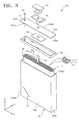
FIG. 3 illustrates an exploded perspective view of the rechargeable battery ofFIG. 1 ; -
FIG. 4 illustrates a cross-sectional view which is taken along line IV - IV ofFIG. 1 ; -
FIG. 5 illustrates a cross-sectional view which is taken along line V - V ofFIG. 2 ; and -
FIGS. 6 to 9 represent a first side surface and a second side surface, which include a first vent and a second vent, according to various embodiments.
-
- Example embodiments will now be described more fully hereinafter with reference to the accompanying drawings; however, they may be embodied in different forms and should not be construed as limited to the embodiments set forth herein. Rather, these embodiments are provided so that this disclosure will be thorough and complete, and will fully convey exemplary implementations to those skilled in the art.
- In the drawing figures, the dimensions of layers and regions may be exaggerated for clarity of illustration. Like reference numerals refer to like elements throughout.
- As used herein, the term "and/or" includes any and all combinations of one or more of the associated listed items. Expressions such as "at least one of," when preceding a list of elements, modify the entire list of elements and do not modify the individual elements of the list. The terms of 1st, 2nd, etc., may be used to describe various components, but components should not be limited by the terms. The terms are only used to distinguish one component from the other components.. Singular expression includes the expression of the plural, unless the context clearly indicates otherwise. In the present application, the term of "including" or "having" must be understood not to preclude one or more other features, numbers, steps, operations, elements, or components, which are described in the specification, or existence of a combination of these things or the additional possibility, but to specify the presence of such features, numbers, steps, operations, elements, components, or any combination of them. On the other hand, to use of "/" may be interpreted as "and" and may be interpreted as "or" on a case-by-case basis.
-
FIG. 1 illustrates a perspective view showing a rechargeable battery according to an embodiment, -
FIG. 2 illustrates a perspective view showing the rechargeable battery ofFIG. 1 when viewed at different angle, andFIG. 3 is an exploded perspective view of the rechargeable battery ofFIG. 1 . - Referring to
FIGS. 1 to 3 , according to an embodiment, arechargeable battery 100 may include anelectrode assembly 110, a can 120 in which theelectrode assembly 110 is accommodated, and acap plate 130 that seals the inside of thecan 120. - The
electrode assembly 110 may include afirst electrode plate 111 and asecond electrode plate 112 that are coated with an electrode active material, and aseparator 113 interposed between thefirst electrode plate 111 and thesecond electrode plate 112. Theelectrode assembly 110 may be manufactured by the following operations of forming a laminate body in which thefirst electrode plate 111, theseparator 113 and thesecond electrode plate 112 are sequentially laminated, and winding the laminate body in the form of a jelly roll. Thefirst electrode plate 111 and thesecond electrode plate 112 are respectively electrically connected to afirst electrode tab 114 and asecond electrode tab 115 in order to externally withdraw charges that are formed by a chemical reaction. Thefirst electrode tab 114 and thesecond electrode tab 115 may extend in an identical direction. For example, the first andsecond electrode tabs can 120. - The present embodiment has been described with respect to the case that the
electrode assembly 110 has the form of a jelly roll. In other implementations, theelectrode assembly 110 may be a laminated structure that includes thefirst electrode plate 111, thesecond electrode plate 112, and theseparator 113, which is interposed between thefirst electrode plate 111 and thesecond electrode plate 112. - The can 120 may be formed into a substantially rectangular parallelepiped shape, and one surface of the
can 120, for example, a surface that corresponds to the upper surface, may be opened. The opened upper surface of thecan 120 may be closed by the substantialrectangular cap plate 130, which has first and second longer side portions 130e1 and 130e2 and first and second shorter side portions 130e3 and 130e4. For example, thecan 120 may include: a first side surface 120s1, which is in parallel with the thickness direction (the "z" direction) of thecap plate 130 and extends along the "z" direction from the first longer side portion 130e1 of thecap plate 130; a second side surface 120s2, which faces the first side surface 120s1 and extends along the "z" direction from the second longer side portion 130e2 of thecap plate 130; a third side surface 120s3, which extends along the "z" direction from the first shorter side portion 130e3 of thecap plate 130; and a fourth side surface 120s4, which extends along the "z" direction from the second shorter side portion 130e4 of thecap plate 130. - The can 120 may be fabricated from a metallic material in order to ensure strength. For example, the
can 120 may be fabricated from aluminum or aluminum alloys. Theelectrode assembly 110 impregnated with an electrolyte may be accommodated in the inside of thecan 120. In order not to cause an undesired short circuit with thecan 120, which is formed of a metallic material, the outer surface of theelectrode assembly 110 may be accommodated in the inside of thecan 120 in a state where theelectrode assembly 110 is surrounded by an insulation sheet (not shown). After theelectrode assembly 110 has been accommodated in the inside of thecan 120, the opening (OP) may be sealed by thecap plate 130. - The
cap plate 130 may seal the opening (OP) of thecan 120, and thus, the inside of thecan 120 may be tightly sealed. For example, thecap plate 130 may be coupled to the upper portion of thecan 120 by laser welding. - An
electrolyte inlet 131 may be provided in thecap plate 130. After thecap plate 130 and thecan 120 are coupled, an electrolyte may be injected through theelectrolyte inlet 131, and theelectrolyte inlet 131 may be sealed by astopper 132. According to another embodiment, theelectrolyte inlet 131 may not be provided in thecap plate 130. In this case, before thecap plate 130 and thecan 120 are integrally coupled by laser welding, the electrolyte may be injected. - An
electrode terminal 140 may be disposed on top of thecap plate 130. The upper surface of theelectrode terminal 140 may be exposed to the outside through the upper portion of thecap plate 130, and the lower portion thereof may penetrate thecap plate 130 to thus be directed toward the inside of thecan 120. - The
cap plate 130, as well as thecan 120, may be also fabricated from a metallic material. Theelectrode terminal 140 may be electrically connected to thefirst electrode tab 114 of theelectrode assembly 110, and thus theelectrode terminal 140 may have a first polarity. Thecap plate 130 may be electrically connected to thesecond electrode tab 115 of theelectrode assembly 110, and thus thecap plate 130 may have a second polarity. For example, thecap plate 130 may serve as a positive electrode of therechargeable battery 100 and theelectrode terminal 140 may serve as a negative electrode of therechargeable battery 100. In order to prevent a short circuit that may occur between thecap plate 130 and theelectrode terminal 140, afirst gasket 145 and a second gasket (not shown) that includes an insulating material may be provided. - The
first gasket 145 may be disposed to contact the upper surface of thecap plate 130, and the second gasket may be disposed to contact the lower surface of thecap plate 130. The present embodiment has been described with respect to a case that the first and second gaskets are separately formed, but in other implementations, the first and second gaskets may be integrally formed. In order that thecan 120, which has a second polarity due to welding of thecan 120 to thecap plate 130, is electrically insulated from external objects or otherrechargeable batteries 100, an insulation film (not shown) that covers the first and second side surfaces 120s1 and 120s2 of thecan 120 may be attached on both sides of thecan 120. - A first insulating
member 150 may be disposed inside thecan 120 at the upper portion of theelectrode assembly 110. The first insulatingmember 150 may insulate theelectrode assembly 110 from thecap plate 130. According to another implementation, the first insulatingmember 150 may insulate theelectrode assembly 110 from thecap plate 130 and at the same time may regulate the movement of theelectrode assembly 110 in the inside of thecan 120. The first insulatingmember 150 may include a through hole so that the first andsecond electrode tabs member 150 may include a hole that is formed at the position corresponding to theelectrolyte inlet 131 so that the electrolyte that flows through theelectrolyte inlet 131 passes through the hole. A second insulating member (not shown) may be disposed at the lower portion of theelectrode assembly 110. Accordingly, an undesired short circuit between thecan 120 made of a metallic material and theelectrode assembly 110 may be prevented. Thefirst vent 121 and thesecond vent 122 are formed on the outer side surface of thecan 120. Accordingly, it may be possible to prevent or reduce the risk of explosion of therechargeable battery 100. If therechargeable battery 100 operates abnormally, gas buildup may occur in the inside of therechargeable battery 100. While the internal gas applies pressure on the inner wall of thecan 120, a swelling phenomenon may occur in which therechargeable battery 100, that is, thecan 120, is expanded. In this case, thefirst vent 121 and/or thesecond vent 122 may be ruptured by the gas buildup that has occurred during an abnormal operation. Accordingly, the gas may be emitted to the outside, thus preventing or reducing the risk of explosion of therechargeable battery 100. - The swelling phenomenon in which the
rechargeable battery 100 is expanded may appear most prominently in the central areas of the first and second side surfaces 120s1 and 120s2, whose mechanical strengths are relatively weak. In general, thecan 120 of therechargeable battery 100 expands the most along the direction of an axis (A), which passes through the centers of the first and second side surfaces. The extent of expansion may form a generally concentric shape around the axis (A). However, if therechargeable battery 100 expands unevenly according to the internal structure of therechargeable battery 100, the occurrence location of the gas may be uneven. If a vent is located on a surface that does not experience as much swelling from gas buildup, the vent may not rupture. In such as case, therechargeable battery 100 may explode despite the existence of a vent. In order to prevent or reduce the risk of such explosion, the first andsecond vents first vent 121 may be formed at the lower portion of the first side surface 120s1, and thesecond vent 122 may be formed at the upper portion of the second side surface 120s2. When at least one of the first andsecond vents rechargeable battery 100 is emitted, and explosion of therechargeable battery 100 may be prevented. -
FIGS. 4 and 5 illustrate lateral cross-sections of the first andsecond vents FIG. 4 illustrates a cross-sectional view that is taken along line IV - IV ofFIG. 1 , andFIG. 5 illustrates a cross-sectional view that is taken along line V - V ofFIG. 2 . - Referring to
FIGS. 4 and 5 , thefirst vent 121 and thesecond vent 122 may be respectively formed on outer surfaces of thecan 120, in the form of a groove. The respective depths d1 and d2 of thefirst vent 121 and thesecond vent 122 are less than the thickness t1 of thecan 120. - The upper portion of the
can 120 forms the opening (OP) and is welded to thecap plate 130. Accordingly, the strength of the upper portion of thecan 120 may be relatively weaker than the strength of the lower portion thereof. Thus, the depth d2 of thesecond vent 122 may be formed to be shallower than the depth d1 of thefirst vent 121. For example, the depths of the first andsecond vents second vents rechargeable battery 100. For example, the maximum value of the depth d2 of thesecond vent 122 may be about 0.5 times the depth d1 of thefirst vent 121. In the case that the depth d2 of thesecond vent 122 were to be greater than 0.5 times the depth d1 of thefirst vent 121, thesecond vent 122 could be easily ruptured even when the internal pressure of therechargeable battery 100 is low, and could be ruptured due to shock that may occur during welding of thecap plate 130 and thecan 120. Therefore, an operational stability of therechargeable battery 100 may be degraded. - The depth d1 of the
first vent 121 may satisfy the following conditional inequality 1 with regard to the thickness "t" of thecan 120.
- In the case that the value of

first vent 121 may be easily ruptured, even when the internal pressure of therechargeable battery 100 is low. Therefore, the operational stability of therechargeable battery 100 may be degraded. On the other hand, in the case that the value of
rechargeable battery 100 is high, thefirst vent 121 may not be ruptured, which could eventually lead to the explosion of therechargeable battery 100. - According to an embodiment, the depth d1 of the
first vent 121 and the thickness "t" of thecan 120 may satisfy the following conditional inequality 2.
-
FIG. 6 represents a first side surface and a second side surface of the rechargeable battery that are respectively shown inFIGS. 1 and2 .FIGS. 7 to 9 represent the first and second side surfaces according to other embodiments. A vent, when formed on an opposite side surface, is shown inFIGS. 6 to 9 as a dotted line. - Referring to
FIGS. 6 to 9 , the first andsecond vents rechargeable battery 100 expands unevenly, the first andsecond vents rechargeable battery 100 is greater than a predetermined pressure. - For example, the
first vent 121 may be formed in the lower-left portion (or the lower-right portion) of the first side surface 120s1, and thesecond vent 122 may be formed in the upper-right portion (or the upper-left portion) of the second side surface 120s2. Thefirst vent 121 may be formed at the lower portion of the first side surface 120s1, and may be disposed in an adjacent area to the third side surface 120s3 on the first side surface 120s1. Thesecond vent 122 may be formed at the upper portion of the second side surface 120s2, and may be disposed in an adjacent area to the fourth side surface 120s4 on the second side surface 120s2. - The first and
second vents FIG. 6 , thefirst vent 121 may extend along an oblique direction with respect to the thickness direction (the "z" direction) of thecap plate 130, and thesecond vent 122 may extend along a parallel direction to the "z" direction. - According to another embodiment, as shown in
FIG. 7 , thefirst vent 121 may extend along an oblique direction with respect to the thickness direction (the "z" direction) of thecap plate 130, and thesecond vent 122 may extend along a perpendicular direction (the "x" direction) to the "z" direction. - According to another embodiment, as shown in
FIG. 8 , thefirst vent 121 may extend along a parallel direction to the thickness direction (the "z" direction) of thecap plate 130, and thesecond vent 122 may extend along an oblique direction with respect to the "z" direction. - According to another embodiment, as shown in
FIG. 9 , thefirst vent 121 may extend along a perpendicular direction (the "x" direction) to the thickness direction (the "z" direction) of thecap plate 130, and thesecond vent 122 may extend along an oblique direction with respect to the "z" direction. - As mentioned above, the first and
second vents rechargeable battery 100 expands unevenly, the first andsecond vents rechargeable battery 100 is greater than a predetermined pressure. - By way of summation and review, rechargeable batteries are being used in a variety of fields. Accordingly, reliability tests according to the use environment of the rechargeable batteries are becoming an important issue. Typical items for the reliability tests include temperature durability, drop strength, electrostatic discharge (ESD), charging and discharging tests, etc. Rechargeable batteries may be used for an extended period of time through charging and discharging. Accordingly, the operating stability of the rechargeable batteries may be an important factor.
- Embodiments provide a structure of a rechargeable battery having vents, in order to prevent explosion due to abnormal operations. Embodiments provide first and second vents formed on different surfaces of a can of a rechargeable battery, and/or at different locations, and/or at different depths. Accordingly, even if the rechargeable battery expands unevenly in an abnormal condition, any one of the first and second vents may be easily ruptured if an internal pressure of the rechargeable battery is higher than a reference pressure. Therefore, the rechargeable battery may be prevented from exploding.
- Example embodiments have been disclosed herein, and although specific terms are employed, they are used and are to be interpreted in a generic and descriptive sense only and not for purpose of limitation. In some instances, as would be apparent to one of ordinary skill in the art as of the filing of the present application, features, characteristics, and/or elements described in connection with a particular embodiment may be used singly or in combination with features, characteristics, and/or elements described in connection with other embodiments unless otherwise specifically indicated. Accordingly, it will be understood by those of skill in the art that various changes in form and details may be made without departing from the scope as set forth in the following claims.
Claims (13)
- A rechargeable battery (100), comprising:an electrode assembly (110) including a first electrode plate (111), a second electrode plate (112), and a separator (113) between the first electrode plate (111) and the second electrode plate (112);a can (120) having an opening (OP) at one side thereof through which the electrode assembly (110) is inserted, the electrode assembly (110) being accommodated in the inside of the can (120); anda cap plate (130) that seals the opening (OP) of the can (120), the cap plate (130) having a thickness in a thickness direction (z),the can (120) including:a first vent (121) on a first side surface (120s1) of the can (120); anda second vent (122) on a second side surface (120s2) of the can (120).
- The rechargeable battery of claim 1, wherein the first side surface (120s1) of the can (120) and the second side surface (120s2) of the can (120) are located on opposite sides of the rechargeable battery (100) from each other.
- The rechargeable battery of claim 1 or 2, wherein
the first vent (121) is on a lower portion of the first side surface (120s1) of the can, and
the second vent (122) is on an upper portion of the second side surface (120s2) of the can. - The rechargeable battery of claim 3, wherein the first vent (121) and the second vent (122) are disposed away from each other.
- The rechargeable battery of claim 3 or 4, wherein
the first vent (121) is on one side of the lower portion of the first side surface (120s1), and the second vent (122) is on one side of the upper portion of the second side surface (120s2). - The rechargeable battery of any of the preceding claims, wherein
the first side surface (120s1) and the second side surface (120s2) extend in the thickness direction (z) of the cap plate (130) from a longer side portion (130e1, 130e2) of the cap plate (130), the first side surface (120s1) and the second side surface (120s2) facing in opposite directions from each other;
a third side surface (120s3) and a fourth side surface (120s4) extend along the thickness direction (z) of the cap plate (130) from a shorter side portion (130e3, 130e4) of the cap plate (130), the third side surface (130e3) and the fourth side surface (130e4) facing in opposite directions from each other; - The rechargeable battery of claim 6 wherein the first vent (121) is on one side of the first side surface (120s1) adjacent to the third side surface (120s3), and
the second vent (122) is on one side of the second side surface (120s2) adjacent to the fourth side surface (120s4). - The rechargeable battery of any of the preceding claims, wherein:any one of the first vent (121) and the second vent (122) extends along an oblique direction with respect to the thickness direction (z) of the cap plate (130), andanother one of the first vent (121) and the second vent (122) extends parallel to the thickness direction (z) of the cap plate (130) or extends along a perpendicular direction (x) with respect to the thickness direction (z) of the cap plate (130).
- The rechargeable battery of one of claims 1-8, wherein
the first vent (121) and the second vent (122) are each in a form of a recess, and
a depth of the first vent (121) is deeper than a depth of the second vent (122). - The rechargeable battery of any of claims 1 - 9, wherein the first vent (121) satisfies a following conditional inequality 1:

where d1 represents the depth of the first vent (121), and t represents a thickness of the can (120). - The rechargeable battery of any of claims 1 - 10, wherein a maximum depth of the second vent (122) is about 0.5 times the depth of the first vent (121).
- The rechargeable battery of one of claims 1 to 11, wherein the depth of the first vent (121) satisfies a following conditional inequality 2:
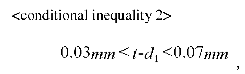
where d1 represents the depth of the first vent (121), and t represents a thickness of the can (120). - The rechargeable battery as claimed in any of the preceding claims, wherein the can (120) is formed of a metallic material.
Applications Claiming Priority (1)
| Application Number | Priority Date | Filing Date | Title |
|---|---|---|---|
| KR1020130010719A KR101440891B1 (en) | 2013-01-30 | 2013-01-30 | Rechargeable Battery |
Publications (2)
| Publication Number | Publication Date |
|---|---|
| EP2763209A1 true EP2763209A1 (en) | 2014-08-06 |
| EP2763209B1 EP2763209B1 (en) | 2022-09-07 |
Family
ID=50000919
Family Applications (1)
| Application Number | Title | Priority Date | Filing Date |
|---|---|---|---|
| EP14153032.9A Active EP2763209B1 (en) | 2013-01-30 | 2014-01-29 | Rechargeable battery |
Country Status (5)
| Country | Link |
|---|---|
| US (1) | US9590218B2 (en) |
| EP (1) | EP2763209B1 (en) |
| JP (1) | JP6319830B2 (en) |
| KR (1) | KR101440891B1 (en) |
| CN (2) | CN110071232B (en) |
Families Citing this family (11)
| Publication number | Priority date | Publication date | Assignee | Title |
|---|---|---|---|---|
| KR102417637B1 (en) * | 2015-10-02 | 2022-07-06 | 삼성에스디아이 주식회사 | A secondary battery |
| CN109565009B (en) * | 2016-08-02 | 2022-05-10 | 松下知识产权经营株式会社 | Battery cover and battery pack |
| KR102245619B1 (en) * | 2016-08-31 | 2021-04-27 | 삼성에스디아이 주식회사 | Battery pack |
| KR102183539B1 (en) * | 2017-04-13 | 2020-11-26 | 주식회사 엘지화학 | Secondary battery |
| KR102511900B1 (en) * | 2017-11-22 | 2023-03-20 | 삼성에스디아이 주식회사 | Secondary battery |
| KR102019682B1 (en) * | 2017-12-08 | 2019-09-09 | 주식회사 엘지화학 | Secondary Battery Case Having Vent Filled with Thermoplastic Resin |
| KR20190140695A (en) * | 2018-06-12 | 2019-12-20 | 삼성에스디아이 주식회사 | Rechargeable battery and battery module |
| KR20210099469A (en) * | 2020-02-04 | 2021-08-12 | 엘지전자 주식회사 | Battery cell |
| KR102747922B1 (en) * | 2022-03-07 | 2024-12-31 | 신흥에스이씨주식회사 | Can for secondary battery and secondary battery comprising the same |
| CN121127990A (en) * | 2023-05-31 | 2025-12-12 | 松下知识产权经营株式会社 | Energy storage device |
| FR3166478A1 (en) * | 2024-09-18 | 2026-03-20 | AMPERE s.a.s | Electrochemical cell with grooves to facilitate disassembly and tooling for such disassembly |
Citations (2)
| Publication number | Priority date | Publication date | Assignee | Title |
|---|---|---|---|---|
| EP1258931A1 (en) * | 2000-02-18 | 2002-11-20 | Matsushita Electric Industrial Co., Ltd. | Safety mechanism for rectangular battery and method of manufacturing the same |
| US20040131924A1 (en) * | 2003-01-03 | 2004-07-08 | David Anglin | Alkaline cell with flat housing |
Family Cites Families (17)
| Publication number | Priority date | Publication date | Assignee | Title |
|---|---|---|---|---|
| KR100349911B1 (en) * | 1999-12-27 | 2002-08-22 | 삼성에스디아이 주식회사 | Prismatic type sealed battery and method for making the same |
| JP4056279B2 (en) * | 2002-03-29 | 2008-03-05 | 松下電器産業株式会社 | battery |
| JP4097482B2 (en) * | 2002-08-19 | 2008-06-11 | 三洋電機株式会社 | Sealed battery with cleavage groove |
| JP4535699B2 (en) * | 2003-07-17 | 2010-09-01 | 三洋電機株式会社 | Sealed battery with cleavage groove |
| KR20050037689A (en) * | 2003-10-20 | 2005-04-25 | 삼성에스디아이 주식회사 | Secondary battery with vents located at optimum positions |
| KR100551885B1 (en) * | 2003-10-20 | 2006-02-10 | 삼성에스디아이 주식회사 | Lithium ion secondary battery |
| US7478033B2 (en) * | 2004-03-16 | 2009-01-13 | Google Inc. | Systems and methods for translating Chinese pinyin to Chinese characters |
| KR20060027674A (en) * | 2004-09-23 | 2006-03-28 | 주식회사 엘지화학 | Rectangular rechargeable battery with improved safety vent |
| KR100788554B1 (en) * | 2006-02-27 | 2007-12-26 | 삼성에스디아이 주식회사 | Secondary battery |
| KR100824878B1 (en) * | 2006-09-15 | 2008-04-23 | 삼성에스디아이 주식회사 | Secondary battery |
| JP3129895U (en) * | 2006-12-19 | 2007-03-08 | 伍必翔 | Plastic battery can safety structure |
| KR100922470B1 (en) * | 2007-09-14 | 2009-10-21 | 삼성에스디아이 주식회사 | Secondary battery |
| KR101023919B1 (en) * | 2008-06-09 | 2011-03-22 | 삼성에스디아이 주식회사 | Lithium secondary battery |
| US9263724B2 (en) * | 2009-10-12 | 2016-02-16 | Samsung Sdi Co., Ltd. | Battery pack |
| KR101082305B1 (en) * | 2009-11-17 | 2011-11-09 | 삼성에스디아이 주식회사 | Case for Secondary Battery and Secondary Battery having the same |
| US8920964B2 (en) * | 2010-05-03 | 2014-12-30 | Samsung Sdi Co., Ltd. | Rechargeable battery |
| JP2013098173A (en) * | 2011-11-01 | 2013-05-20 | Hitachi Maxell Ltd | Sealed battery |
-
2013
- 2013-01-30 KR KR1020130010719A patent/KR101440891B1/en active Active
- 2013-07-03 JP JP2013139806A patent/JP6319830B2/en active Active
- 2013-11-08 US US14/074,887 patent/US9590218B2/en active Active
-
2014
- 2014-01-09 CN CN201910228004.8A patent/CN110071232B/en active Active
- 2014-01-09 CN CN201410009492.0A patent/CN103972443A/en active Pending
- 2014-01-29 EP EP14153032.9A patent/EP2763209B1/en active Active
Patent Citations (2)
| Publication number | Priority date | Publication date | Assignee | Title |
|---|---|---|---|---|
| EP1258931A1 (en) * | 2000-02-18 | 2002-11-20 | Matsushita Electric Industrial Co., Ltd. | Safety mechanism for rectangular battery and method of manufacturing the same |
| US20040131924A1 (en) * | 2003-01-03 | 2004-07-08 | David Anglin | Alkaline cell with flat housing |
Also Published As
| Publication number | Publication date |
|---|---|
| CN110071232A (en) | 2019-07-30 |
| EP2763209B1 (en) | 2022-09-07 |
| KR101440891B1 (en) | 2014-09-17 |
| CN110071232B (en) | 2022-06-28 |
| KR20140097938A (en) | 2014-08-07 |
| US9590218B2 (en) | 2017-03-07 |
| CN103972443A (en) | 2014-08-06 |
| JP2014150045A (en) | 2014-08-21 |
| JP6319830B2 (en) | 2018-05-09 |
| US20140212709A1 (en) | 2014-07-31 |
Similar Documents
| Publication | Publication Date | Title |
|---|---|---|
| EP2763209B1 (en) | Rechargeable battery | |
| KR100914115B1 (en) | Secondary battery | |
| EP2930764B1 (en) | Rechargeable battery | |
| EP2879203A1 (en) | Secondary battery | |
| EP2747168B1 (en) | Rechargeable battery with housing having specified radii of curvature | |
| EP2985807B1 (en) | Rechargeable battery comprising a cap plate with a chamfered portion | |
| EP2854201B1 (en) | Rechargeable battery | |
| US20170033325A1 (en) | Rechargeable battery including multiple cases | |
| JP6448107B2 (en) | Secondary battery | |
| EP3062367B1 (en) | Rechargeable battery | |
| EP2175506A2 (en) | Secondary battery | |
| JP2005332824A (en) | Secondary battery | |
| EP2509133A1 (en) | Rechargeable battery | |
| US10135058B2 (en) | Rechargeable battery with multi-layer vent | |
| US9887411B2 (en) | Rechargeable battery | |
| EP2551934A1 (en) | Rechargeable battery | |
| US9627662B2 (en) | Secondary battery | |
| KR20170053394A (en) | Beading-less cap assembly with modifed gasket material | |
| KR102296130B1 (en) | Rechargeable battery | |
| KR20180001884A (en) | Rechargeable battery | |
| EP2953188A1 (en) | Rechargeable battery | |
| KR20170053392A (en) | Beading-less cap assembly with modifed gasket structure | |
| KR20170053387A (en) | Beading-less cap assembly with inverse vent structure | |
| KR20170053391A (en) | Beading-less cap assembly with improved sealing function |
Legal Events
| Date | Code | Title | Description |
|---|---|---|---|
| PUAI | Public reference made under article 153(3) epc to a published international application that has entered the european phase |
Free format text: ORIGINAL CODE: 0009012 |
|
| 17P | Request for examination filed |
Effective date: 20140129 |
|
| AK | Designated contracting states |
Kind code of ref document: A1 Designated state(s): AL AT BE BG CH CY CZ DE DK EE ES FI FR GB GR HR HU IE IS IT LI LT LU LV MC MK MT NL NO PL PT RO RS SE SI SK SM TR |
|
| AX | Request for extension of the european patent |
Extension state: BA ME |
|
| R17P | Request for examination filed (corrected) |
Effective date: 20150204 |
|
| RBV | Designated contracting states (corrected) |
Designated state(s): AL AT BE BG CH CY CZ DE DK EE ES FI FR GB GR HR HU IE IS IT LI LT LU LV MC MK MT NL NO PL PT RO RS SE SI SK SM TR |
|
| 17Q | First examination report despatched |
Effective date: 20160708 |
|
| STAA | Information on the status of an ep patent application or granted ep patent |
Free format text: STATUS: EXAMINATION IS IN PROGRESS |
|
| REG | Reference to a national code |
Ref country code: DE Ref legal event code: R079 Ref document number: 602014084849 Country of ref document: DE Free format text: PREVIOUS MAIN CLASS: H01M0002120000 Ipc: H01M0010040000 |
|
| RIC1 | Information provided on ipc code assigned before grant |
Ipc: H01M 50/342 20210101ALI20220306BHEP Ipc: H01M 50/15 20210101ALI20220306BHEP Ipc: H01M 50/103 20210101ALI20220306BHEP Ipc: H01M 10/04 20060101AFI20220306BHEP |
|
| GRAP | Despatch of communication of intention to grant a patent |
Free format text: ORIGINAL CODE: EPIDOSNIGR1 |
|
| STAA | Information on the status of an ep patent application or granted ep patent |
Free format text: STATUS: GRANT OF PATENT IS INTENDED |
|
| INTG | Intention to grant announced |
Effective date: 20220420 |
|
| GRAS | Grant fee paid |
Free format text: ORIGINAL CODE: EPIDOSNIGR3 |
|
| GRAA | (expected) grant |
Free format text: ORIGINAL CODE: 0009210 |
|
| STAA | Information on the status of an ep patent application or granted ep patent |
Free format text: STATUS: THE PATENT HAS BEEN GRANTED |
|
| AK | Designated contracting states |
Kind code of ref document: B1 Designated state(s): AL AT BE BG CH CY CZ DE DK EE ES FI FR GB GR HR HU IE IS IT LI LT LU LV MC MK MT NL NO PL PT RO RS SE SI SK SM TR |
|
| REG | Reference to a national code |
Ref country code: GB Ref legal event code: FG4D |
|
| REG | Reference to a national code |
Ref country code: CH Ref legal event code: EP Ref country code: AT Ref legal event code: REF Ref document number: 1517808 Country of ref document: AT Kind code of ref document: T Effective date: 20220915 |
|
| REG | Reference to a national code |
Ref country code: DE Ref legal event code: R096 Ref document number: 602014084849 Country of ref document: DE |
|
| REG | Reference to a national code |
Ref country code: IE Ref legal event code: FG4D |
|
| REG | Reference to a national code |
Ref country code: LT Ref legal event code: MG9D |
|
| REG | Reference to a national code |
Ref country code: NL Ref legal event code: MP Effective date: 20220907 |
|
| PG25 | Lapsed in a contracting state [announced via postgrant information from national office to epo] |
Ref country code: SE Free format text: LAPSE BECAUSE OF FAILURE TO SUBMIT A TRANSLATION OF THE DESCRIPTION OR TO PAY THE FEE WITHIN THE PRESCRIBED TIME-LIMIT Effective date: 20220907 Ref country code: RS Free format text: LAPSE BECAUSE OF FAILURE TO SUBMIT A TRANSLATION OF THE DESCRIPTION OR TO PAY THE FEE WITHIN THE PRESCRIBED TIME-LIMIT Effective date: 20220907 Ref country code: NO Free format text: LAPSE BECAUSE OF FAILURE TO SUBMIT A TRANSLATION OF THE DESCRIPTION OR TO PAY THE FEE WITHIN THE PRESCRIBED TIME-LIMIT Effective date: 20221207 Ref country code: LV Free format text: LAPSE BECAUSE OF FAILURE TO SUBMIT A TRANSLATION OF THE DESCRIPTION OR TO PAY THE FEE WITHIN THE PRESCRIBED TIME-LIMIT Effective date: 20220907 Ref country code: LT Free format text: LAPSE BECAUSE OF FAILURE TO SUBMIT A TRANSLATION OF THE DESCRIPTION OR TO PAY THE FEE WITHIN THE PRESCRIBED TIME-LIMIT Effective date: 20220907 Ref country code: FI Free format text: LAPSE BECAUSE OF FAILURE TO SUBMIT A TRANSLATION OF THE DESCRIPTION OR TO PAY THE FEE WITHIN THE PRESCRIBED TIME-LIMIT Effective date: 20220907 Ref country code: ES Free format text: LAPSE BECAUSE OF FAILURE TO SUBMIT A TRANSLATION OF THE DESCRIPTION OR TO PAY THE FEE WITHIN THE PRESCRIBED TIME-LIMIT Effective date: 20220907 |
|
| REG | Reference to a national code |
Ref country code: AT Ref legal event code: MK05 Ref document number: 1517808 Country of ref document: AT Kind code of ref document: T Effective date: 20220907 |
|
| PG25 | Lapsed in a contracting state [announced via postgrant information from national office to epo] |
Ref country code: HR Free format text: LAPSE BECAUSE OF FAILURE TO SUBMIT A TRANSLATION OF THE DESCRIPTION OR TO PAY THE FEE WITHIN THE PRESCRIBED TIME-LIMIT Effective date: 20220907 Ref country code: GR Free format text: LAPSE BECAUSE OF FAILURE TO SUBMIT A TRANSLATION OF THE DESCRIPTION OR TO PAY THE FEE WITHIN THE PRESCRIBED TIME-LIMIT Effective date: 20221208 |
|
| PG25 | Lapsed in a contracting state [announced via postgrant information from national office to epo] |
Ref country code: SM Free format text: LAPSE BECAUSE OF FAILURE TO SUBMIT A TRANSLATION OF THE DESCRIPTION OR TO PAY THE FEE WITHIN THE PRESCRIBED TIME-LIMIT Effective date: 20220907 Ref country code: RO Free format text: LAPSE BECAUSE OF FAILURE TO SUBMIT A TRANSLATION OF THE DESCRIPTION OR TO PAY THE FEE WITHIN THE PRESCRIBED TIME-LIMIT Effective date: 20220907 Ref country code: PT Free format text: LAPSE BECAUSE OF FAILURE TO SUBMIT A TRANSLATION OF THE DESCRIPTION OR TO PAY THE FEE WITHIN THE PRESCRIBED TIME-LIMIT Effective date: 20230109 Ref country code: CZ Free format text: LAPSE BECAUSE OF FAILURE TO SUBMIT A TRANSLATION OF THE DESCRIPTION OR TO PAY THE FEE WITHIN THE PRESCRIBED TIME-LIMIT Effective date: 20220907 Ref country code: AT Free format text: LAPSE BECAUSE OF FAILURE TO SUBMIT A TRANSLATION OF THE DESCRIPTION OR TO PAY THE FEE WITHIN THE PRESCRIBED TIME-LIMIT Effective date: 20220907 |
|
| PG25 | Lapsed in a contracting state [announced via postgrant information from national office to epo] |
Ref country code: SK Free format text: LAPSE BECAUSE OF FAILURE TO SUBMIT A TRANSLATION OF THE DESCRIPTION OR TO PAY THE FEE WITHIN THE PRESCRIBED TIME-LIMIT Effective date: 20220907 Ref country code: PL Free format text: LAPSE BECAUSE OF FAILURE TO SUBMIT A TRANSLATION OF THE DESCRIPTION OR TO PAY THE FEE WITHIN THE PRESCRIBED TIME-LIMIT Effective date: 20220907 Ref country code: IS Free format text: LAPSE BECAUSE OF FAILURE TO SUBMIT A TRANSLATION OF THE DESCRIPTION OR TO PAY THE FEE WITHIN THE PRESCRIBED TIME-LIMIT Effective date: 20230107 Ref country code: EE Free format text: LAPSE BECAUSE OF FAILURE TO SUBMIT A TRANSLATION OF THE DESCRIPTION OR TO PAY THE FEE WITHIN THE PRESCRIBED TIME-LIMIT Effective date: 20220907 |
|
| REG | Reference to a national code |
Ref country code: DE Ref legal event code: R097 Ref document number: 602014084849 Country of ref document: DE |
|
| PG25 | Lapsed in a contracting state [announced via postgrant information from national office to epo] |
Ref country code: NL Free format text: LAPSE BECAUSE OF FAILURE TO SUBMIT A TRANSLATION OF THE DESCRIPTION OR TO PAY THE FEE WITHIN THE PRESCRIBED TIME-LIMIT Effective date: 20220907 Ref country code: AL Free format text: LAPSE BECAUSE OF FAILURE TO SUBMIT A TRANSLATION OF THE DESCRIPTION OR TO PAY THE FEE WITHIN THE PRESCRIBED TIME-LIMIT Effective date: 20220907 |
|
| P01 | Opt-out of the competence of the unified patent court (upc) registered |
Effective date: 20230528 |
|
| PLBE | No opposition filed within time limit |
Free format text: ORIGINAL CODE: 0009261 |
|
| STAA | Information on the status of an ep patent application or granted ep patent |
Free format text: STATUS: NO OPPOSITION FILED WITHIN TIME LIMIT |
|
| PG25 | Lapsed in a contracting state [announced via postgrant information from national office to epo] |
Ref country code: DK Free format text: LAPSE BECAUSE OF FAILURE TO SUBMIT A TRANSLATION OF THE DESCRIPTION OR TO PAY THE FEE WITHIN THE PRESCRIBED TIME-LIMIT Effective date: 20220907 |
|
| 26N | No opposition filed |
Effective date: 20230608 |
|
| PG25 | Lapsed in a contracting state [announced via postgrant information from national office to epo] |
Ref country code: SI Free format text: LAPSE BECAUSE OF FAILURE TO SUBMIT A TRANSLATION OF THE DESCRIPTION OR TO PAY THE FEE WITHIN THE PRESCRIBED TIME-LIMIT Effective date: 20220907 |
|
| REG | Reference to a national code |
Ref country code: CH Ref legal event code: PL |
|
| PG25 | Lapsed in a contracting state [announced via postgrant information from national office to epo] |
Ref country code: LU Free format text: LAPSE BECAUSE OF NON-PAYMENT OF DUE FEES Effective date: 20230129 |
|
| REG | Reference to a national code |
Ref country code: BE Ref legal event code: MM Effective date: 20230131 |
|
| PG25 | Lapsed in a contracting state [announced via postgrant information from national office to epo] |
Ref country code: LI Free format text: LAPSE BECAUSE OF NON-PAYMENT OF DUE FEES Effective date: 20230131 Ref country code: CH Free format text: LAPSE BECAUSE OF NON-PAYMENT OF DUE FEES Effective date: 20230131 |
|
| PG25 | Lapsed in a contracting state [announced via postgrant information from national office to epo] |
Ref country code: BE Free format text: LAPSE BECAUSE OF NON-PAYMENT OF DUE FEES Effective date: 20230131 |
|
| PG25 | Lapsed in a contracting state [announced via postgrant information from national office to epo] |
Ref country code: IE Free format text: LAPSE BECAUSE OF NON-PAYMENT OF DUE FEES Effective date: 20230129 |
|
| PG25 | Lapsed in a contracting state [announced via postgrant information from national office to epo] |
Ref country code: IT Free format text: LAPSE BECAUSE OF FAILURE TO SUBMIT A TRANSLATION OF THE DESCRIPTION OR TO PAY THE FEE WITHIN THE PRESCRIBED TIME-LIMIT Effective date: 20220907 |
|
| PG25 | Lapsed in a contracting state [announced via postgrant information from national office to epo] |
Ref country code: MC Free format text: LAPSE BECAUSE OF FAILURE TO SUBMIT A TRANSLATION OF THE DESCRIPTION OR TO PAY THE FEE WITHIN THE PRESCRIBED TIME-LIMIT Effective date: 20220907 |
|
| PG25 | Lapsed in a contracting state [announced via postgrant information from national office to epo] |
Ref country code: MC Free format text: LAPSE BECAUSE OF FAILURE TO SUBMIT A TRANSLATION OF THE DESCRIPTION OR TO PAY THE FEE WITHIN THE PRESCRIBED TIME-LIMIT Effective date: 20220907 |
|
| PG25 | Lapsed in a contracting state [announced via postgrant information from national office to epo] |
Ref country code: BG Free format text: LAPSE BECAUSE OF FAILURE TO SUBMIT A TRANSLATION OF THE DESCRIPTION OR TO PAY THE FEE WITHIN THE PRESCRIBED TIME-LIMIT Effective date: 20220907 |
|
| PG25 | Lapsed in a contracting state [announced via postgrant information from national office to epo] |
Ref country code: BG Free format text: LAPSE BECAUSE OF FAILURE TO SUBMIT A TRANSLATION OF THE DESCRIPTION OR TO PAY THE FEE WITHIN THE PRESCRIBED TIME-LIMIT Effective date: 20220907 |
|
| PG25 | Lapsed in a contracting state [announced via postgrant information from national office to epo] |
Ref country code: CY Free format text: LAPSE BECAUSE OF FAILURE TO SUBMIT A TRANSLATION OF THE DESCRIPTION OR TO PAY THE FEE WITHIN THE PRESCRIBED TIME-LIMIT; INVALID AB INITIO Effective date: 20140129 |
|
| PG25 | Lapsed in a contracting state [announced via postgrant information from national office to epo] |
Ref country code: HU Free format text: LAPSE BECAUSE OF FAILURE TO SUBMIT A TRANSLATION OF THE DESCRIPTION OR TO PAY THE FEE WITHIN THE PRESCRIBED TIME-LIMIT; INVALID AB INITIO Effective date: 20140129 |
|
| PG25 | Lapsed in a contracting state [announced via postgrant information from national office to epo] |
Ref country code: TR Free format text: LAPSE BECAUSE OF FAILURE TO SUBMIT A TRANSLATION OF THE DESCRIPTION OR TO PAY THE FEE WITHIN THE PRESCRIBED TIME-LIMIT Effective date: 20220907 |
|
| PGFP | Annual fee paid to national office [announced via postgrant information from national office to epo] |
Ref country code: FR Payment date: 20251231 Year of fee payment: 13 |
|
| PGFP | Annual fee paid to national office [announced via postgrant information from national office to epo] |
Ref country code: GB Payment date: 20260106 Year of fee payment: 13 |
|
| PGFP | Annual fee paid to national office [announced via postgrant information from national office to epo] |
Ref country code: DE Payment date: 20251230 Year of fee payment: 13 |