EP2763153A1 - Electromagnetic relay - Google Patents
Electromagnetic relay Download PDFInfo
- Publication number
- EP2763153A1 EP2763153A1 EP20130838841 EP13838841A EP2763153A1 EP 2763153 A1 EP2763153 A1 EP 2763153A1 EP 20130838841 EP20130838841 EP 20130838841 EP 13838841 A EP13838841 A EP 13838841A EP 2763153 A1 EP2763153 A1 EP 2763153A1
- Authority
- EP
- European Patent Office
- Prior art keywords
- contact
- electromagnetic relay
- permanent magnet
- fixed contact
- movable
- Prior art date
- Legal status (The legal status is an assumption and is not a legal conclusion. Google has not performed a legal analysis and makes no representation as to the accuracy of the status listed.)
- Granted
Links
Images


Classifications
-
- H—ELECTRICITY
- H01—ELECTRIC ELEMENTS
- H01H—ELECTRIC SWITCHES; RELAYS; SELECTORS; EMERGENCY PROTECTIVE DEVICES
- H01H50/00—Details of electromagnetic relays
- H01H50/54—Contact arrangements
-
- H—ELECTRICITY
- H01—ELECTRIC ELEMENTS
- H01H—ELECTRIC SWITCHES; RELAYS; SELECTORS; EMERGENCY PROTECTIVE DEVICES
- H01H9/00—Details of switching devices, not covered by groups H01H1/00 - H01H7/00
- H01H9/30—Means for extinguishing or preventing arc between current-carrying parts
- H01H9/34—Stationary parts for restricting or subdividing the arc, e.g. barrier plate
- H01H9/36—Metal parts
-
- H—ELECTRICITY
- H01—ELECTRIC ELEMENTS
- H01H—ELECTRIC SWITCHES; RELAYS; SELECTORS; EMERGENCY PROTECTIVE DEVICES
- H01H50/00—Details of electromagnetic relays
- H01H50/54—Contact arrangements
- H01H50/546—Contact arrangements for contactors having bridging contacts
-
- H—ELECTRICITY
- H01—ELECTRIC ELEMENTS
- H01H—ELECTRIC SWITCHES; RELAYS; SELECTORS; EMERGENCY PROTECTIVE DEVICES
- H01H9/00—Details of switching devices, not covered by groups H01H1/00 - H01H7/00
- H01H9/30—Means for extinguishing or preventing arc between current-carrying parts
- H01H9/44—Means for extinguishing or preventing arc between current-carrying parts using blow-out magnet
- H01H9/443—Means for extinguishing or preventing arc between current-carrying parts using blow-out magnet using permanent magnets
Definitions
- the present invention relates to electromagnetic relays that turn on and off electrical apparatuses.
- electromagnetic relays include those for domestic use, industrial use, and on-vehicle use.
- an electromagnetic relay as described in Patent Document 1 referenced below allows and interrupts a flow of electric current in an electrical circuit by closing and opening a pair of contacts formed by a fixed contact and a movable contact.
- Patent Document 1 Japanese Laid-Open Patent Application No. 2012-89484
- the present invention has an object of providing an electromagnetic relay capable of improving the arc extinguishing effect irrespective of its external size.
- an electromagnetic relay includes a contact that includes a fixed contact and a movable contact, wherein the movable contact is displaceable in a first direction to move toward the fixed contact and in a second direction to move away from the fixed contact, a permanent magnet provided on a peripheral side of the contact, wherein the permanent magnet has a polarity direction perpendicular to the first and second directions, and a non-magnetic body that faces toward a direction of a Lorentz force that acts based on the permanent magnet in a direct electric current flowing through the contact.
- an electromagnetic relay capable of improving the arc extinguishing effect with improved make-and-break performance.
- FIG. 1 is a schematic diagram illustrating part of an electromagnetic relay according to a first embodiment, viewed in a direction in which a movable contact moves away (separates) from a fixed contact.
- FIG. 2 is a schematic diagram illustrating part of an electromagnetic relay according to the first embodiment, viewed in a direction toward a permanent magnet.
- an electromagnetic relay 1 includes a fixed contact 2 and a movable contact 3, which is displaceable in directions toward and away from the fixed contact 2.
- the fixed contact 2 and the movable contact 3 have a columnar shape and form a contact 100.
- An electric current flows in a direction I (the direction going into the plane of the paper of FIG. 1 ) at the contact 100.
- the fixed contact 2 and the movable contact 3 are arranged side by side to face each other in the direction I.
- the direction I coincides with the direction in which the movable contact 3 moves away from the fixed contact 2.
- the electromagnetic relay 1 further includes a permanent magnet 4.
- the permanent magnet 4 has a north pole N and a south pole S as illustrated in FIG. 1 .
- a direction from the north pole N to the south pole S and a direction from the south pole S to the north pole N are the magnetic directions of the permanent magnet 4, which are indicated by a double-headed arrow NS.
- the direction of a Lorentz force that acts on an arc at the contact 100 is indicated by an arrow R in FIG. 1 .
- the permanent magnet 4 is placed beside the contact 100 on its peripheral side so that its magnetic directions NS are perpendicular to the direction I and the direction R. That is, the magnetic directions NS are perpendicular to the directions in which the movable contact 3 moves toward and away from the fixed contact 2.
- the electromagnetic relay 1 further includes a metal plate 5 (a non-magnetic body) having a flat plate shape.
- the metal plate 5 is placed beside the contact 100 so as to be perpendicular to the direction R, which is perpendicular to both the magnetic directions NS and the direction I.
- the metal plate 5 faces toward the direction of the Lorentz force that acts based on the permanent magnet 4 in a direct electric current flowing through the contact 100.
- FIG. 1 illustrates a case where an electric current flows from the fixed contact 2 to the movable contact 3 at the contact 100.
- an arc discharge AI is generated with an arcuate shape that continues from the movable contact 3 to the fixed contact 2 when viewed in a direction toward the north pole side of the permanent magnet 4 with the fixed contact 2, forming the positive electrode of the contact 100, and the movable contact 3, forming the negative electrode of the contact 100, being arranged side by side.
- the arc discharge AI (also simply referred to as "arc") starts when an electric current starts to flow through an air gap, that is, a gap, between a surface of the fixed contact 2 and a surface of the movable contact 3 with an electrical load being imposed between the fixed contact 2 and the movable contact 3 connected to a power supply E and an appropriate resistor R1 to form a closed circuit as illustrated in FIG. 2 .
- the surfaces of the fixed contact 2 and the movable contact 3 are heated at the boundary between the surface of the fixed contact 2 and the arc discharge AI and the boundary between the surface of the movable contact 3 and the arc discharge AI, that is, a positive electrode root part and a negative electrode root part, respectively.
- the positive electrode root part is heated by electron impact and the negative electrode root part is heated by ion impact.
- the positive electrode and the negative electrode are also heated by heat conduction and radiation from the arc discharge AI. This heating at both the positive electrode and the negative electrode causes the material of the positive electrode and the negative electrode to evaporate, so that the wear of both the fixed contact 2 and the movable contact 3 increases.
- the generated arc discharge AI is more effectively extinguished by appropriately arranging a non-magnetic body and a permanent magnet.
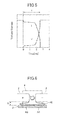
- FIG. 3 is a schematic diagram illustrating a cross section of the electromagnetic relay 1 that passes the central axis line of a movable iron core and a shaft core.
- the electromagnetic relay 1 is a plunger type and is a one-from-X type, which has one pair of contacts with respect to a shaft core. That is, as illustrated in FIG. 3 , the electromagnetic relay 1 includes a pair of right and left contacts 100.
- the fixed contact 2 of the left contact 100 is connected to a positive terminal 6 and the fixed contact 2 of the right contact 100 is connected to a negative terminal 7.
- FIG. 2 illustrates a combination of a positive electrode and a negative electrode at the left contact 100 in FIG. 3 .
- the positions of the fixed contact 2 and the movable contact 3 illustrated in FIG. 2 are reversed at the right contact 100 in FIG. 3 .
- the movable contacts 3 of the right and left contacts 100 are placed at the right end and the left end, respectively, of a movable part 8 having a rectangular parallelepiped shape.
- the movable part 8 is connected to a shaft core 9 via a contact pressure spring 10.
- An upper end portion of the shaft core 9 in FIG. 3 is connected to a housing 11, which fixes the positive terminal 6 and the negative terminal 7, via a return spring 12 and an E-type retaining ring 13.
- a lower end portion of the shaft core 9 is connected to a hole, which has a bottom, of a movable iron core 14 so as to be slidable in its axial directions.
- the electromagnetic relay 1 includes a pair of metal plates 5.
- the metal plates 5 are formed of, or formed using as a principal component, one of non-magnetic materials, which are not ferromagnetic materials, such as copper, aluminum, stainless steel, and silver.
- the shape of the metal plates 5 may be a flat plate shape as illustrated in the conceptual diagrams of FIG. 1 and FIG. 2 .
- each of the metal plates 5 preferably has an external cover shape that externally covers the contact surfaces of the contact 100 from radial directions with respect to the directions in which the movable contact 3 moves toward and away from the fixed contact 2 as a center as illustrated in (a) of FIG. 4 .
- a letter U column shape is selected as an example of this external cover shape.
- the housing 11 includes a pair of recesses 11a where these metal plates 5 of a letter U column shape may be accommodated and fixed by press fitting.
- Each of the recesses 11a is positioned on the outer peripheral side of the corresponding contact 100, and is shaped so as to allow the corresponding metal plate 5 of a letter U column shape to be press-fitted into the recess 11a from the direction in which the movable contact 3 moves away from the fixed contact 2 (from the upward direction in (a) of FIG. 4 ).
- the paired metal plates 5 are press-fitted and fixed to the corresponding recesses 11a as illustrated in (b) of FIG. 4 .
- the electromagnetic relay 1 includes a pair of permanent magnets 4 having a flat plate shape
- the housing 11 further includes a pair of recesses 11b where the permanent magnets 4 may be accommodated and fixed by press fitting.
- the paired permanent magnets 4 are press-fitted and fixed to the corresponding recesses 11b.
- the internal space of the housing 11, which is a box component is subjected to neither evacuation nor gas injection.
- the coil wire 16 includes a terminal portion, which is not illustrated in FIG. 3 . With no excitation current applied to this terminal portion, the shaft core 9 and the movable iron core 14 are urged downward in FIG. 3 based on the urging force of the return spring 12, so that a transition to the open state of the contacts 100, each formed of the fixed contact 2 and the movable contact 3, is made or the open state of the contacts 100 is maintained.
- an excitation current is applied to the terminal portion, a force to attract the movable iron core 14 upward in FIG. 3 , generated by the coil wire 16, the yoke 15, and the yoke 18, causes the shaft core 9 and the movable part 8 to move upward, so that the movable contacts 3 come into contact with the corresponding fixed contacts 2 to close the contacts 100.
- a voltage V and a current I show waveforms illustrated in FIG. 5 .
- the current I gradually decreases for approximately 2 ms, and thereafter, rapidly drops.
- the voltage V gradually increases for approximately 2 ms, and thereafter, rapidly rises to reach a predetermined value.
- An arc interruption time T at the contacts 100 of the electromagnetic relay 1 is the time from the stepwise decrease of the current I to the final arrival of the voltage V at the predetermined value.
- a shorter arc interruption time T indicates that a shorter time is required to extinguish the arc discharge AI.
- the relationship between the arc interruption time T and a distance D between each of the fixed contact 2 and the movable contact 3 of each of the contacts 100 and the corresponding metal plate 5 in a direction in which the arc discharge AI is blown off in FIG. 6 is a gradual decrease of the arc interruption time T relative to a decrease in the distance D as illustrated in FIG. 7 .
- the side face of the fixed contact 2 is substantially the positive terminal 6 or the negative terminal 7, and if the positive terminal 6 or the negative terminal 7 includes, for example, an iron-based ferromagnetic material, the arc discharge AI enters the positive terminal 6 or the negative terminal 7.
- the distance D is set to a value greater than a minimum value of 1 mm, for example, approximately 1.5 mm (a predetermined range).
- the electromagnetic relay 1 of the first embodiment by providing the permanent magnet 4 and the non-magnetic metal plate 5 that have the above-described predetermined positional relationship near each of the contacts 100, it is possible to obtain the following effects.
- the metal plate 5 has a flat plate shape for convenience of illustration.
- the electromagnetic relay 1 of the first embodiment it is possible to deflect and blow off the arc discharge AI, generated between the fixed contact 2 and the movable contact 3 at each of the contacts 100 when the movable contact 3 moves toward and away from the fixed contact 2, toward a direction away from the contact 100 by an electromagnetic force (Lorentz force) based on Fleming's left-hand rule, generated by a magnetic flux generated by the permanent magnet 4 and the arc discharge AI, and to cause the blown-off arc discharge AI to collide with the metal plate 5 (a non-magnetic body).
- an electromagnetic force Lientz force
- the arc discharge AI forms an arcuate shape and simply bulges radially as illustrated in (a) of FIG. 8 , while by providing the metal plates 5, which are non-magnetic bodies, it is possible to elongate the arc discharge AI on the surfaces of the metal plates 5 without the arc discharge AI entering the metal plates 5 as illustrated in (b) of FIG. 8 . Therefore, the thermal energy of the arc discharge AI is absorbed by the metal plates 5 over a wider area, and the extension distance of the arc discharge AI in a space is increased, so that it is possible to extinguish the arc discharge AI more effectively.
- the metal plates 5 of the first embodiment also serve to prevent the collision of the arc discharge AI with the housing 11. Therefore, it is possible to prevent the housing 11 from being damaged by the arc discharge AI and to prevent degradation of the contact characteristics of each of the contacts 100 by preventing generation of gas due to damage to resin that forms the housing 11. Furthermore, because it is possible to prevent generation of gas by preventing damage to the housing 11 serving as a box component, it is possible to reduce cost by subjecting the internal space of the housing 11 to neither evacuation nor gas injection.
- both the permanent magnets 4 and the metal plates 5 are fixed to the housing 11, serving as a box component forming an outer shell, by press fitting.
- the permanent magnets 4 and the metal plates 5 may be unitarily fixed to the housing 11 by being embedded in advance in the housing 11 by insert molding.
- FIG. 9 illustrates an outline of an electromagnetic relay 21 according to the second embodiment, and (b) is an enlarged view of part of the electromagnetic relay 21.
- the electromagnetic relay 21 of the second embodiment is an application of the present invention to an arm-type and one-from-X type electromagnetic relay.
- a fixed contact 22 and a movable contact 23, which form a contact 100 face toward each other in directions in which the movable contact 23 moves toward and away from the fixed contact 22, and a permanent magnet 24 is positioned to face toward a direction from the supporting point to the end point of a movable arm 23A, which supports the movable contact 23.
- a non-magnetic metal plate 25 is positioned to face toward a direction in which an arc discharge AI, flowing in the direction in which the movable contact 23 moves toward or away from the fixed contact 22, is blown off by a Lorentz force acting on the arc discharge AI because of the magnetic force of the permanent magnet 24.
- the metal plate 25 is provided on the side of the supporting point of the movable arm 23A relative to the permanent magnet 24.
- the movable arm 23A is connected to a positive terminal 26 and the fixed contact 22 is connected to a negative terminal 27.
- a housing, serving as a box component that forms an outer shell, and a drive part, including a coil wire and yokes for driving the movable arm 23A, which form the electromagnetic relay 21, are functionally equal in structure to those of the plunger-type electromagnetic relay 1 of the first embodiment, and accordingly, their detailed description is omitted.
- the electromagnetic relay 21 of the second embodiment is an arm type, and in terms of ensuring a space required for the swinging of the movable arm 23a, it is not appropriate to provide the metal plate 25 in such a manner as to externally cover the contact 100 around the direction in which the movable contact 23 moves toward and away from the fixed contact 22. Therefore, the metal plate 25 has a flat plate shape.
- the electromagnetic relay 21 of the second embodiment it is possible to deflect and blow off the arc discharge AI, generated between the fixed contact 22 and the movable contact 23 when the movable contact 23 moves toward and away from the fixed contact 22, toward a direction away from the contact 100 by an electromagnetic force (Lorentz force) based on Fleming's left-hand rule, generated by a magnetic flux generated by the permanent magnet 24 and the arc discharge AI, and to cause the blown-off arc discharge AI to collide with the metal plate 25 (a non-magnetic body).
- an electromagnetic force Liperentz force
- the present invention relates to electromagnetic relays, and makes it possible to improve downsizability and to improve the arc extinguishing effect and the interrupting performance of a contact. Therefore, the application of the present invention to domestic, industrial, and on-vehicle electromagnetic relays is beneficial.
Abstract
Description
- The present invention relates to electromagnetic relays that turn on and off electrical apparatuses. Examples of electromagnetic relays include those for domestic use, industrial use, and on-vehicle use.
- For example, an electromagnetic relay as described in
Patent Document 1 referenced below allows and interrupts a flow of electric current in an electrical circuit by closing and opening a pair of contacts formed by a fixed contact and a movable contact. There is concern about generation of an arc when a voltage becomes higher than a minimum arc voltage or an electric current becomes larger than a minimum arc current at the time of the fixed contact and the movable contact in contact with each other separating from each other with a movement of the movable contact in a direction away from the fixed contact or the fixed contact and the movable contact out of contact with each other moving toward each other with a movement of the movable contact in a direction toward the fixed contact. - [Patent Document 1] Japanese Laid-Open Patent Application No.
2012-89484 - In the electromagnetic relay as described in
Patent Document 1, the technique of extinguishing an arc by deflecting and blowing off the arc by bending its direction by causing an electromagnetic force (Lorentz force) based on Fleming's left-hand rule to act on the arc based on the magnetic flux of a magnet positioned near the contacts, using the fact that an arc has the same magnetic properties as an electric current, may be applied. In the case of considering improving the interrupting performance by deflecting and elongating an arc, however, it becomes more difficult to ensure a space for elongating an arc as the electromagnetic relay becomes smaller in external size, so that there is a problem in that improvement in the arc extinguishing effect and reduction in size may not be fully achieved at the same time. - The present invention has an object of providing an electromagnetic relay capable of improving the arc extinguishing effect irrespective of its external size.
- According to an aspect of the present invention, an electromagnetic relay includes a contact that includes a fixed contact and a movable contact, wherein the movable contact is displaceable in a first direction to move toward the fixed contact and in a second direction to move away from the fixed contact, a permanent magnet provided on a peripheral side of the contact, wherein the permanent magnet has a polarity direction perpendicular to the first and second directions, and a non-magnetic body that faces toward a direction of a Lorentz force that acts based on the permanent magnet in a direct electric current flowing through the contact.
- According to an aspect of the present invention, it is possible to provide an electromagnetic relay capable of improving the arc extinguishing effect with improved make-and-break performance.
-
-
FIG. 1 is a schematic diagram illustrating part of an electromagnetic relay according to a first embodiment of the present invention. -
FIG. 2 is a schematic diagram illustrating part of the electromagnetic relay according to the first embodiment. -
FIG. 3 is a cross-sectional view of the electromagnetic relay according to the first embodiment. -
FIG. 4 is a schematic diagram illustrating shapes of non-magnetic bodies of the electromagnetic relay and their fixation to a box component according to the first embodiment. -
FIG. 5 is a schematic graph illustrating the definition of an arc interruption time that serves as grounds for the determination of a distance between non-magnetic bodies and corresponding contacts of the electromagnetic relay according to the first embodiment. -
FIG. 6 is a schematic diagram illustrating the details of arc extinction in the electromagnetic relay according to the first embodiment, viewed in a direction toward a permanent magnet. -
FIG. 7 is a schematic graph illustrating a characteristic that is a correlation between an arc interruption time and a distance between non-magnetic bodies and corresponding contacts of the electromagnetic relay according to the first embodiment. -
FIG. 8 is a schematic diagram illustrating arc extinction in theelectromagnetic relay 1 according to the first embodiment based on a comparison with related art. -
FIG. 9 is a schematic diagram illustrating an outline and part of an electromagnetic relay according to a second embodiment of the present invention. - Embodiments of the present invention are described below with reference to the accompanying drawings.
-
FIG. 1 is a schematic diagram illustrating part of an electromagnetic relay according to a first embodiment, viewed in a direction in which a movable contact moves away (separates) from a fixed contact.FIG. 2 is a schematic diagram illustrating part of an electromagnetic relay according to the first embodiment, viewed in a direction toward a permanent magnet. - Referring to
FIG. 1 and FIG. 2 , anelectromagnetic relay 1 according to the first embodiment includes a fixedcontact 2 and amovable contact 3, which is displaceable in directions toward and away from thefixed contact 2. The fixedcontact 2 and themovable contact 3 have a columnar shape and form acontact 100. An electric current flows in a direction I (the direction going into the plane of the paper ofFIG. 1 ) at thecontact 100. The fixedcontact 2 and themovable contact 3 are arranged side by side to face each other in the direction I. The direction I coincides with the direction in which themovable contact 3 moves away from thefixed contact 2. - The
electromagnetic relay 1 further includes apermanent magnet 4. Thepermanent magnet 4 has a north pole N and a south pole S as illustrated inFIG. 1 . A direction from the north pole N to the south pole S and a direction from the south pole S to the north pole N are the magnetic directions of thepermanent magnet 4, which are indicated by a double-headed arrow NS. The direction of a Lorentz force that acts on an arc at thecontact 100 is indicated by an arrow R inFIG. 1 . Thepermanent magnet 4 is placed beside thecontact 100 on its peripheral side so that its magnetic directions NS are perpendicular to the direction I and the direction R. That is, the magnetic directions NS are perpendicular to the directions in which themovable contact 3 moves toward and away from thefixed contact 2. - The
electromagnetic relay 1 further includes a metal plate 5 (a non-magnetic body) having a flat plate shape. Themetal plate 5 is placed beside thecontact 100 so as to be perpendicular to the direction R, which is perpendicular to both the magnetic directions NS and the direction I. Themetal plate 5 faces toward the direction of the Lorentz force that acts based on thepermanent magnet 4 in a direct electric current flowing through thecontact 100.FIG. 1 illustrates a case where an electric current flows from thefixed contact 2 to themovable contact 3 at thecontact 100. - That is, as illustrated in
FIG. 2 , an arc discharge AI is generated with an arcuate shape that continues from themovable contact 3 to thefixed contact 2 when viewed in a direction toward the north pole side of thepermanent magnet 4 with thefixed contact 2, forming the positive electrode of thecontact 100, and themovable contact 3, forming the negative electrode of thecontact 100, being arranged side by side. - The arc discharge AI (also simply referred to as "arc") starts when an electric current starts to flow through an air gap, that is, a gap, between a surface of the
fixed contact 2 and a surface of themovable contact 3 with an electrical load being imposed between thefixed contact 2 and themovable contact 3 connected to a power supply E and an appropriate resistor R1 to form a closed circuit as illustrated inFIG. 2 . The surfaces of thefixed contact 2 and themovable contact 3 are heated at the boundary between the surface of thefixed contact 2 and the arc discharge AI and the boundary between the surface of themovable contact 3 and the arc discharge AI, that is, a positive electrode root part and a negative electrode root part, respectively. The positive electrode root part is heated by electron impact and the negative electrode root part is heated by ion impact. The positive electrode and the negative electrode are also heated by heat conduction and radiation from the arc discharge AI. This heating at both the positive electrode and the negative electrode causes the material of the positive electrode and the negative electrode to evaporate, so that the wear of both thefixed contact 2 and themovable contact 3 increases. - Therefore, according to the
electromagnetic relay 1 of the first embodiment, in the light of both improvement of the durability and improvement of the interrupting performance of thecontact 100, the generated arc discharge AI is more effectively extinguished by appropriately arranging a non-magnetic body and a permanent magnet. - Next, an overall configuration of the
electromagnetic relay 1 of the first embodiment is described.FIG. 3 is a schematic diagram illustrating a cross section of theelectromagnetic relay 1 that passes the central axis line of a movable iron core and a shaft core. As illustrated inFIG. 3 , theelectromagnetic relay 1 is a plunger type and is a one-from-X type, which has one pair of contacts with respect to a shaft core. That is, as illustrated inFIG. 3 , theelectromagnetic relay 1 includes a pair of right andleft contacts 100. InFIG. 3 , thefixed contact 2 of theleft contact 100 is connected to apositive terminal 6 and thefixed contact 2 of theright contact 100 is connected to anegative terminal 7.FIG. 2 illustrates a combination of a positive electrode and a negative electrode at theleft contact 100 inFIG. 3 . The positions of the fixedcontact 2 and themovable contact 3 illustrated inFIG. 2 are reversed at theright contact 100 inFIG. 3 . - The
movable contacts 3 of the right andleft contacts 100 are placed at the right end and the left end, respectively, of amovable part 8 having a rectangular parallelepiped shape. Themovable part 8 is connected to ashaft core 9 via acontact pressure spring 10. An upper end portion of theshaft core 9 inFIG. 3 is connected to ahousing 11, which fixes thepositive terminal 6 and thenegative terminal 7, via areturn spring 12 and anE-type retaining ring 13. A lower end portion of theshaft core 9 is connected to a hole, which has a bottom, of amovable iron core 14 so as to be slidable in its axial directions. - An
annular yoke 15 is provided around themovable iron core 14. Acoil wire 16 is wound and provided around theyoke 15. Abarrier 17 for electromagnetic shielding is provided around thecoil wire 16. Ayoke 18 having a bottom lid shape, which is suitably joined to thehousing 11, is provided to support and enclose both a lower end portion of the yoke inFIG. 3 and thecoil wire 16. Theelectromagnetic relay 1 includes a pair ofmetal plates 5. Themetal plates 5 are formed of, or formed using as a principal component, one of non-magnetic materials, which are not ferromagnetic materials, such as copper, aluminum, stainless steel, and silver. The shape of themetal plates 5 may be a flat plate shape as illustrated in the conceptual diagrams ofFIG. 1 and FIG. 2 . In view of the elongation of the arc discharge AI blown off by a Lorentz force on the surface of each of themetal plates 5, however, each of themetal plates 5 preferably has an external cover shape that externally covers the contact surfaces of thecontact 100 from radial directions with respect to the directions in which themovable contact 3 moves toward and away from the fixedcontact 2 as a center as illustrated in (a) ofFIG. 4 . In (a) ofFIG. 4 , a letter U column shape is selected as an example of this external cover shape. Thehousing 11 includes a pair ofrecesses 11a where thesemetal plates 5 of a letter U column shape may be accommodated and fixed by press fitting. Each of therecesses 11a is positioned on the outer peripheral side of thecorresponding contact 100, and is shaped so as to allow the correspondingmetal plate 5 of a letter U column shape to be press-fitted into therecess 11a from the direction in which themovable contact 3 moves away from the fixed contact 2 (from the upward direction in (a) ofFIG. 4 ). The pairedmetal plates 5 are press-fitted and fixed to thecorresponding recesses 11a as illustrated in (b) ofFIG. 4 . Furthermore, as illustrated in (a) ofFIG. 4 , theelectromagnetic relay 1 includes a pair ofpermanent magnets 4 having a flat plate shape, and thehousing 11 further includes a pair ofrecesses 11b where thepermanent magnets 4 may be accommodated and fixed by press fitting. The pairedpermanent magnets 4 are press-fitted and fixed to the correspondingrecesses 11b. Furthermore, the internal space of thehousing 11, which is a box component, is subjected to neither evacuation nor gas injection. - The
coil wire 16 includes a terminal portion, which is not illustrated inFIG. 3 . With no excitation current applied to this terminal portion, theshaft core 9 and themovable iron core 14 are urged downward inFIG. 3 based on the urging force of thereturn spring 12, so that a transition to the open state of thecontacts 100, each formed of the fixedcontact 2 and themovable contact 3, is made or the open state of thecontacts 100 is maintained. When an excitation current is applied to the terminal portion, a force to attract themovable iron core 14 upward inFIG. 3 , generated by thecoil wire 16, theyoke 15, and theyoke 18, causes theshaft core 9 and themovable part 8 to move upward, so that themovable contacts 3 come into contact with the corresponding fixedcontacts 2 to close thecontacts 100. - When measured before and after the interruption of an arc at the
contact 100 on the closed circuit illustrated inFIG. 2 , a voltage V and a current I show waveforms illustrated inFIG. 5 . After decreasing stepwise at the beginning of the interruption, the current I gradually decreases for approximately 2 ms, and thereafter, rapidly drops. After increasing stepwise at the beginning of the interruption, the voltage V gradually increases for approximately 2 ms, and thereafter, rapidly rises to reach a predetermined value. - An arc interruption time T at the
contacts 100 of theelectromagnetic relay 1 is the time from the stepwise decrease of the current I to the final arrival of the voltage V at the predetermined value. A shorter arc interruption time T indicates that a shorter time is required to extinguish the arc discharge AI. The relationship between the arc interruption time T and a distance D between each of the fixedcontact 2 and themovable contact 3 of each of thecontacts 100 and the correspondingmetal plate 5 in a direction in which the arc discharge AI is blown off inFIG. 6 is a gradual decrease of the arc interruption time T relative to a decrease in the distance D as illustrated inFIG. 7 . - In causing the arc discharge AI blown off by a Lorentz force to collide with the
metal plates 5 more effectively, it is possible to ensure higher collision energy with a shorter distance D. Too small a distance D, however, makes it impossible to ensure a gap required to elongate the arc discharge AI into an inverted Ω shape as illustrated inFIG. 6 between a side face of the fixedcontact 2 or a side face of themovable contact 3 of each of thecontacts 100 and the correspondingmetal plate 5.
In addition, the side face of the fixedcontact 2 is substantially thepositive terminal 6 or thenegative terminal 7, and if thepositive terminal 6 or thenegative terminal 7 includes, for example, an iron-based ferromagnetic material, the arc discharge AI enters thepositive terminal 6 or thenegative terminal 7. - In this case, the arc discharge AI is prevented from being sufficiently elongated along the surface of the
metal plate 5 between each of thecontacts 100 and the correspondingmetal plate 5. Therefore, when the characteristic illustrated inFIG. 7 is obtained by an experiment or a simulation in theelectromagnetic relay 1 of the first embodiment, the distance D is set to a value greater than a minimum value of 1 mm, for example, approximately 1.5 mm (a predetermined range). - According to the
electromagnetic relay 1 of the first embodiment, by providing thepermanent magnet 4 and thenon-magnetic metal plate 5 that have the above-described predetermined positional relationship near each of thecontacts 100, it is possible to obtain the following effects. - That is, when the arc discharge AI generated in the gap between the
fixed contact 2 and themovable contact 3 with the opening or closing of each of thecontacts 100 is blown off by a Lorentz force, it is possible to elongate the arcuate arc discharge AI along the surface of themetal plate 5 as illustrated inFIG. 6 because the metal plate is disposed so as to face toward the direction of the acting Lorentz force. InFIG. 6 , themetal plate 5 has a flat plate shape for convenience of illustration. - That is, according to the
electromagnetic relay 1 of the first embodiment, it is possible to deflect and blow off the arc discharge AI, generated between thefixed contact 2 and themovable contact 3 at each of thecontacts 100 when themovable contact 3 moves toward and away from the fixedcontact 2, toward a direction away from thecontact 100 by an electromagnetic force (Lorentz force) based on Fleming's left-hand rule, generated by a magnetic flux generated by thepermanent magnet 4 and the arc discharge AI, and to cause the blown-off arc discharge AI to collide with the metal plate 5 (a non-magnetic body). By elongating the arc discharge AI in a plane direction of themetal plate 5 by this collision and causing the thermal energy of the arc discharge AI to be absorbed by the non-magnetic body, and making a distance over which the arc discharge AI extends between thefixed contact 2 and themovable contact 3 as long as possible, it is possible to extinguish the arc discharge AI more swiftly. - That is, in the case where no
metal plate 5 is provided in the direction in which the arc discharge AI is blown off by a Lorentz force, the arc discharge AI forms an arcuate shape and simply bulges radially as illustrated in (a) ofFIG. 8 , while by providing themetal plates 5, which are non-magnetic bodies, it is possible to elongate the arc discharge AI on the surfaces of themetal plates 5 without the arc discharge AI entering themetal plates 5 as illustrated in (b) ofFIG. 8 . Therefore, the thermal energy of the arc discharge AI is absorbed by themetal plates 5 over a wider area, and the extension distance of the arc discharge AI in a space is increased, so that it is possible to extinguish the arc discharge AI more effectively. - Furthermore, the
metal plates 5 of the first embodiment also serve to prevent the collision of the arc discharge AI with thehousing 11. Therefore, it is possible to prevent thehousing 11 from being damaged by the arc discharge AI and to prevent degradation of the contact characteristics of each of thecontacts 100 by preventing generation of gas due to damage to resin that forms thehousing 11. Furthermore, because it is possible to prevent generation of gas by preventing damage to thehousing 11 serving as a box component, it is possible to reduce cost by subjecting the internal space of thehousing 11 to neither evacuation nor gas injection. - In addition, by minimizing, by providing the
metal plates 5, a space required to ensure the interrupting performance by elongating the arc discharge AI and reducing its thermal energy, it is possible to downsize thehousing 11 and also the entireelectromagnetic relay 1. In other words, it is possible to improve the interrupting performance irrespective of the external size of an electromagnetic relay. - According to the
electromagnetic relay 1 of the first embodiment, both thepermanent magnets 4 and themetal plates 5 are fixed to thehousing 11, serving as a box component forming an outer shell, by press fitting. Alternatively, thepermanent magnets 4 and themetal plates 5 may be unitarily fixed to thehousing 11 by being embedded in advance in thehousing 11 by insert molding. - By employing the latter molding method, it is possible to fix the
permanent magnets 4 and themetal plates 5 to thehousing 11 by insert molding in a single process, so that it is possible to improve assemblability and manufacturability. - In the above-described first embodiment, the case where the present invention is applied to a plunger-type electromagnetic relay is illustrated, while the present invention may also be applied to an arm-type (hinge-type) electromagnetic relay. A second embodiment, where the present invention is applied to an arm-type electromagnetic relay, is described below. In
FIG. 9, (a) illustrates an outline of anelectromagnetic relay 21 according to the second embodiment, and (b) is an enlarged view of part of theelectromagnetic relay 21. - As illustrated in (a) of
FIG. 9 , theelectromagnetic relay 21 of the second embodiment is an application of the present invention to an arm-type and one-from-X type electromagnetic relay. As illustrated in (b) ofFIG. 9 , a fixedcontact 22 and amovable contact 23, which form acontact 100, face toward each other in directions in which themovable contact 23 moves toward and away from the fixedcontact 22, and apermanent magnet 24 is positioned to face toward a direction from the supporting point to the end point of amovable arm 23A, which supports themovable contact 23. Anon-magnetic metal plate 25 is positioned to face toward a direction in which an arc discharge AI, flowing in the direction in which themovable contact 23 moves toward or away from the fixedcontact 22, is blown off by a Lorentz force acting on the arc discharge AI because of the magnetic force of thepermanent magnet 24. Themetal plate 25 is provided on the side of the supporting point of themovable arm 23A relative to thepermanent magnet 24. Themovable arm 23A is connected to apositive terminal 26 and the fixedcontact 22 is connected to anegative terminal 27. - A housing, serving as a box component that forms an outer shell, and a drive part, including a coil wire and yokes for driving the
movable arm 23A, which form theelectromagnetic relay 21, are functionally equal in structure to those of the plunger-typeelectromagnetic relay 1 of the first embodiment, and accordingly, their detailed description is omitted. Theelectromagnetic relay 21 of the second embodiment is an arm type, and in terms of ensuring a space required for the swinging of the movable arm 23a, it is not appropriate to provide themetal plate 25 in such a manner as to externally cover thecontact 100 around the direction in which themovable contact 23 moves toward and away from the fixedcontact 22. Therefore, themetal plate 25 has a flat plate shape. - According to the
electromagnetic relay 21 of the second embodiment as well, it is possible to deflect and blow off the arc discharge AI, generated between the fixedcontact 22 and themovable contact 23 when themovable contact 23 moves toward and away from the fixedcontact 22, toward a direction away from thecontact 100 by an electromagnetic force (Lorentz force) based on Fleming's left-hand rule, generated by a magnetic flux generated by thepermanent magnet 24 and the arc discharge AI, and to cause the blown-off arc discharge AI to collide with the metal plate 25 (a non-magnetic body). Based on this collision, like in the first embodiment, it is possible to extinguish the arc discharge AI more swiftly by weakening the arc discharge AI by elongating the arc discharge AI in a plane direction of themetal plate 25 and causing the thermal energy of the arc discharge AI to be absorbed by the non-magnetic body, and making the extension distance of the arc discharge AI between the fixedcontact 22 and themovable contact 23 as long as possible. Like in the first embodiment, it is also possible to obtain the housing protection effect and the downsizing effect in the second embodiment. - Preferred embodiments of the present invention are described in detail above. The present invention, however, is not limited to the above-described embodiments, and variations and modifications may be made to the above-described embodiments without departing from the scope of the present invention.
- The present invention relates to electromagnetic relays, and makes it possible to improve downsizability and to improve the arc extinguishing effect and the interrupting performance of a contact. Therefore, the application of the present invention to domestic, industrial, and on-vehicle electromagnetic relays is beneficial.
-
- 1
- electromagnetic relay
- 2
- fixed contact
- 3
- movable contact
- 4
- permanent magnet
- 5
- metal plate (non-magnetic body)
- 6
- positive terminal
- 7
- negative terminal
- 8
- movable part
- 9
- shaft core
- 10
- contact pressure spring
- 11
- housing
- 12
- return spring
- 13
- E-type retaining ring (retainer)
- 14
- movable iron core
- 15
- yoke
- 16
- coil wire
- 17
- barrier
- 18
- yoke
- 21
- electromagnetic relay
- 22
- fixed contact
- 23
- movable contact
- 23A
- movable arm
- 24
- permanent magnet
- 25
- metal plate (non-magnetic body)
- 26
- positive terminal
- 27
- negative terminal
Claims (5)
- An electromagnetic relay, comprising:a contact that includes a fixed contact and a movable contact, wherein the movable contact is displaceable in a first direction to move toward the fixed contact and in a second direction to move away from the fixed contact;a permanent magnet provided on a peripheral side of the contact, wherein the permanent magnet has a polarity direction perpendicular to the first and second directions; anda non-magnetic body that faces toward a direction of a Lorentz force that acts based on the permanent magnet in a direct electric current flowing through the contact.
- The electromagnetic relay as claimed in claim 1, wherein the non-magnetic body has a flat plate shape or an external cover shape that covers the contact.
- The electromagnetic relay as claimed in claim 1, wherein a distance between the non-magnetic body and the contact is determined to be in a predetermined range based on a characteristic between the distance and a breaking time of the contact.
- The electromagnetic relay as claimed in claim 1, further comprising:a box component that forms an outer shell,wherein the permanent magnet and the non-magnetic body are fixed to the box component by being press-fitted into corresponding recesses of the box component.
- The electromagnetic relay as claimed in claim 4, wherein the box component has an internal space subjected to neither evacuation nor gas injection.
Applications Claiming Priority (2)
| Application Number | Priority Date | Filing Date | Title |
|---|---|---|---|
| JP2012208953A JP5946382B2 (en) | 2012-09-21 | 2012-09-21 | Electromagnetic relay |
| PCT/JP2013/074513 WO2014045963A1 (en) | 2012-09-21 | 2013-09-11 | Electromagnetic relay |
Publications (3)
| Publication Number | Publication Date |
|---|---|
| EP2763153A1 true EP2763153A1 (en) | 2014-08-06 |
| EP2763153A4 EP2763153A4 (en) | 2015-05-27 |
| EP2763153B1 EP2763153B1 (en) | 2016-06-15 |
Family
ID=50341277
Family Applications (1)
| Application Number | Title | Priority Date | Filing Date |
|---|---|---|---|
| EP13838841.8A Not-in-force EP2763153B1 (en) | 2012-09-21 | 2013-09-11 | Electromagnetic relay |
Country Status (6)
| Country | Link |
|---|---|
| US (1) | US9330872B2 (en) |
| EP (1) | EP2763153B1 (en) |
| JP (1) | JP5946382B2 (en) |
| KR (1) | KR101631000B1 (en) |
| CN (1) | CN103907169B (en) |
| WO (1) | WO2014045963A1 (en) |
Cited By (2)
| Publication number | Priority date | Publication date | Assignee | Title |
|---|---|---|---|---|
| EP3306634A1 (en) * | 2016-10-05 | 2018-04-11 | Fujitsu Component Limited | Electromagnetic relay |
| EP4120308A3 (en) * | 2021-07-16 | 2023-03-22 | Fujitsu Component Limited | Relay |
Families Citing this family (12)
| Publication number | Priority date | Publication date | Assignee | Title |
|---|---|---|---|---|
| US10090127B2 (en) * | 2013-06-28 | 2018-10-02 | Panasonic Intellectual Property Management Co., Ltd. | Contact device and electromagnetic relay mounted with same |
| JP6202943B2 (en) * | 2013-08-26 | 2017-09-27 | 富士通コンポーネント株式会社 | Electromagnetic relay |
| JP6265657B2 (en) * | 2013-08-26 | 2018-01-24 | 富士通コンポーネント株式会社 | Electromagnetic relay |
| JP6433706B2 (en) | 2014-07-28 | 2018-12-05 | 富士通コンポーネント株式会社 | Electromagnetic relay and coil terminal |
| EP3086351B1 (en) * | 2015-04-22 | 2017-08-30 | Ellenberger & Poensgen GmbH | Power relay for a vehicle |
| KR101943365B1 (en) * | 2015-10-14 | 2019-01-29 | 엘에스산전 주식회사 | Direct Relay |
| KR102531475B1 (en) * | 2016-02-02 | 2023-05-11 | 엘에스일렉트릭(주) | Relay |
| JP6536472B2 (en) * | 2016-04-28 | 2019-07-03 | 株式会社デンソー | solenoid |
| JP6995337B2 (en) * | 2017-08-04 | 2022-01-14 | 松川精密股▲ふん▼有限公司 | relay |
| KR20210025959A (en) * | 2019-08-28 | 2021-03-10 | 엘에스일렉트릭(주) | Arc path forming part and direct current relay include the same |
| TWI772120B (en) * | 2021-07-23 | 2022-07-21 | 松川精密股份有限公司 | Electromagnetic Relay |
| KR20230075641A (en) | 2021-11-23 | 2023-05-31 | 엘에스일렉트릭(주) | Arc inducement part and direct current relay include the same |
Family Cites Families (19)
| Publication number | Priority date | Publication date | Assignee | Title |
|---|---|---|---|---|
| US5583328A (en) * | 1992-07-02 | 1996-12-10 | Mitsubishi Denki Kabushiki Kaisha | High voltage switch including U-shaped, slitted stationary contact assembly with arc extinguishing/magnetic blowout features |
| JP2996808B2 (en) * | 1992-07-02 | 2000-01-11 | 三菱電機株式会社 | Switch |
| JP3321963B2 (en) * | 1994-02-22 | 2002-09-09 | 株式会社デンソー | Plunger type electromagnetic relay |
| DE69936026T2 (en) * | 1998-08-26 | 2007-08-16 | Matsushita Electric Works, Ltd., Kadoma | Single-pole switch arrangement with relays |
| US6700466B1 (en) * | 1999-10-14 | 2004-03-02 | Matsushita Electric Works, Ltd. | Contactor |
| US20020018332A1 (en) | 2000-07-04 | 2002-02-14 | Matthias Kroeker | Arrangement having a contact element which can be brought into contact with another contact element |
| JP3778081B2 (en) * | 2001-12-25 | 2006-05-24 | 三菱電機株式会社 | Arc extinguishing device and on-vehicle switch using the same |
| JP2004311389A (en) * | 2003-02-21 | 2004-11-04 | Sumitomo Electric Ind Ltd | Dc relay |
| JP2005026182A (en) * | 2003-07-02 | 2005-01-27 | Matsushita Electric Works Ltd | Electromagnetic switching device |
| JP2007305468A (en) | 2006-05-12 | 2007-11-22 | Omron Corp | Electromagnetic relay |
| US7982564B2 (en) * | 2008-06-30 | 2011-07-19 | Remy Technologies, Llc | Starter solenoid with vibration resistant features |
| US8354906B2 (en) * | 2008-09-05 | 2013-01-15 | Anden Co., Ltd. | Electromagnetic relay |
| JP5560058B2 (en) * | 2010-01-26 | 2014-07-23 | 富士通コンポーネント株式会社 | Electromagnetic relay |
| WO2011147458A1 (en) * | 2010-05-28 | 2011-12-01 | Abb Research Ltd | A dc switching device |
| KR101086908B1 (en) | 2010-10-15 | 2011-11-25 | 엘에스산전 주식회사 | Electromagnetic switch |
| JP5806562B2 (en) * | 2011-01-12 | 2015-11-10 | 富士電機株式会社 | Magnetic contactor |
| JP5684650B2 (en) * | 2011-05-19 | 2015-03-18 | 富士電機株式会社 | Magnetic contactor |
| JP5966469B2 (en) * | 2012-03-15 | 2016-08-10 | オムロン株式会社 | Sealed contact device |
| JP5991848B2 (en) * | 2012-04-27 | 2016-09-14 | 日本特殊陶業株式会社 | relay |
-
2012
- 2012-09-21 JP JP2012208953A patent/JP5946382B2/en not_active Expired - Fee Related
-
2013
- 2013-09-11 KR KR1020147011623A patent/KR101631000B1/en active IP Right Grant
- 2013-09-11 WO PCT/JP2013/074513 patent/WO2014045963A1/en active Application Filing
- 2013-09-11 CN CN201380003664.7A patent/CN103907169B/en not_active Expired - Fee Related
- 2013-09-11 EP EP13838841.8A patent/EP2763153B1/en not_active Not-in-force
-
2014
- 2014-04-25 US US14/261,512 patent/US9330872B2/en not_active Expired - Fee Related
Cited By (3)
| Publication number | Priority date | Publication date | Assignee | Title |
|---|---|---|---|---|
| EP3306634A1 (en) * | 2016-10-05 | 2018-04-11 | Fujitsu Component Limited | Electromagnetic relay |
| US10658141B2 (en) | 2016-10-05 | 2020-05-19 | Fujitsu Component Limited | Electromagnetic relay |
| EP4120308A3 (en) * | 2021-07-16 | 2023-03-22 | Fujitsu Component Limited | Relay |
Also Published As
| Publication number | Publication date |
|---|---|
| WO2014045963A1 (en) | 2014-03-27 |
| JP2014063675A (en) | 2014-04-10 |
| KR101631000B1 (en) | 2016-06-15 |
| KR20140069327A (en) | 2014-06-09 |
| EP2763153A4 (en) | 2015-05-27 |
| US20140232489A1 (en) | 2014-08-21 |
| US9330872B2 (en) | 2016-05-03 |
| EP2763153B1 (en) | 2016-06-15 |
| CN103907169A (en) | 2014-07-02 |
| CN103907169B (en) | 2016-10-12 |
| JP5946382B2 (en) | 2016-07-06 |
Similar Documents
| Publication | Publication Date | Title |
|---|---|---|
| EP2763153B1 (en) | Electromagnetic relay | |
| JP5560058B2 (en) | Electromagnetic relay | |
| KR101451536B1 (en) | Contact device, and electromagnetic switch using same | |
| EP1906430B1 (en) | Electrical switching apparatus including a split core slot motor and method of installing a slot motor assembly in a circuit interrupter | |
| JP6066598B2 (en) | Electromagnetic relay | |
| JP2011155005A (en) | Electromagnetic switch | |
| TW201310489A (en) | Electromagnetic relay and method of manufacturing the same | |
| US20100165532A1 (en) | Fault current limiter | |
| US11830694B2 (en) | Direct current relay | |
| EP3557600B1 (en) | Stationary contact assembly and corresponding switch contact | |
| US11264192B2 (en) | Circuit interrupter | |
| US20150170857A1 (en) | Electromagnetic actuator for a medium voltage vacuum circuit breaker | |
| EP3384512B1 (en) | Electrical switching apparatus and slot motor therefor | |
| JP4544172B2 (en) | Electromagnetic relay | |
| CN109920704A (en) | Anti- Lorentz force relay | |
| KR20160119007A (en) | Short-circuit release having an optimized coil connection | |
| CN102237230B (en) | Double interrupted protective switching device for monitoring circuit | |
| JP2009152024A (en) | Reed switch | |
| US20240096580A1 (en) | Electromagnetic relay | |
| WO2021215525A1 (en) | Arc restriction mechanism | |
| US20240128034A1 (en) | Electromagnetic relay | |
| JP2003308773A (en) | Electromagnetic relay and mounting method thereof | |
| KR101116385B1 (en) | Relay | |
| US11728114B2 (en) | Low-voltage switching device including an electromagnetic contact load support | |
| JP2022013329A (en) | Gas sealed switch |
Legal Events
| Date | Code | Title | Description |
|---|---|---|---|
| PUAI | Public reference made under article 153(3) epc to a published international application that has entered the european phase |
Free format text: ORIGINAL CODE: 0009012 |
|
| 17P | Request for examination filed |
Effective date: 20140430 |
|
| AK | Designated contracting states |
Kind code of ref document: A1 Designated state(s): AL AT BE BG CH CY CZ DE DK EE ES FI FR GB GR HR HU IE IS IT LI LT LU LV MC MK MT NL NO PL PT RO RS SE SI SK SM TR |
|
| RA4 | Supplementary search report drawn up and despatched (corrected) |
Effective date: 20150424 |
|
| RIC1 | Information provided on ipc code assigned before grant |
Ipc: H01H 9/44 20060101AFI20150420BHEP Ipc: H01H 50/54 20060101ALI20150420BHEP Ipc: H01H 9/36 20060101ALN20150420BHEP |
|
| REG | Reference to a national code |
Ref country code: DE Ref legal event code: R079 Ref document number: 602013008669 Country of ref document: DE Free format text: PREVIOUS MAIN CLASS: H01H0050380000 Ipc: H01H0009440000 |
|
| DAX | Request for extension of the european patent (deleted) | ||
| GRAP | Despatch of communication of intention to grant a patent |
Free format text: ORIGINAL CODE: EPIDOSNIGR1 |
|
| RIC1 | Information provided on ipc code assigned before grant |
Ipc: H01H 9/44 20060101AFI20151209BHEP Ipc: H01H 50/54 20060101ALI20151209BHEP Ipc: H01H 9/36 20060101ALN20151209BHEP |
|
| RIC1 | Information provided on ipc code assigned before grant |
Ipc: H01H 9/44 20060101AFI20151217BHEP Ipc: H01H 9/36 20060101ALN20151217BHEP Ipc: H01H 50/54 20060101ALI20151217BHEP |
|
| INTG | Intention to grant announced |
Effective date: 20160107 |
|
| GRAS | Grant fee paid |
Free format text: ORIGINAL CODE: EPIDOSNIGR3 |
|
| GRAA | (expected) grant |
Free format text: ORIGINAL CODE: 0009210 |
|
| AK | Designated contracting states |
Kind code of ref document: B1 Designated state(s): AL AT BE BG CH CY CZ DE DK EE ES FI FR GB GR HR HU IE IS IT LI LT LU LV MC MK MT NL NO PL PT RO RS SE SI SK SM TR |
|
| REG | Reference to a national code |
Ref country code: CH Ref legal event code: EP Ref country code: GB Ref legal event code: FG4D |
|
| REG | Reference to a national code |
Ref country code: IE Ref legal event code: FG4D |
|
| REG | Reference to a national code |
Ref country code: AT Ref legal event code: REF Ref document number: 806858 Country of ref document: AT Kind code of ref document: T Effective date: 20160715 |
|
| REG | Reference to a national code |
Ref country code: DE Ref legal event code: R096 Ref document number: 602013008669 Country of ref document: DE |
|
| REG | Reference to a national code |
Ref country code: FR Ref legal event code: PLFP Year of fee payment: 4 |
|
| REG | Reference to a national code |
Ref country code: LT Ref legal event code: MG4D |
|
| REG | Reference to a national code |
Ref country code: NL Ref legal event code: MP Effective date: 20160615 |
|
| PG25 | Lapsed in a contracting state [announced via postgrant information from national office to epo] |
Ref country code: LT Free format text: LAPSE BECAUSE OF FAILURE TO SUBMIT A TRANSLATION OF THE DESCRIPTION OR TO PAY THE FEE WITHIN THE PRESCRIBED TIME-LIMIT Effective date: 20160615 Ref country code: NO Free format text: LAPSE BECAUSE OF FAILURE TO SUBMIT A TRANSLATION OF THE DESCRIPTION OR TO PAY THE FEE WITHIN THE PRESCRIBED TIME-LIMIT Effective date: 20160915 Ref country code: FI Free format text: LAPSE BECAUSE OF FAILURE TO SUBMIT A TRANSLATION OF THE DESCRIPTION OR TO PAY THE FEE WITHIN THE PRESCRIBED TIME-LIMIT Effective date: 20160615 |
|
| REG | Reference to a national code |
Ref country code: AT Ref legal event code: MK05 Ref document number: 806858 Country of ref document: AT Kind code of ref document: T Effective date: 20160615 |
|
| PG25 | Lapsed in a contracting state [announced via postgrant information from national office to epo] |
Ref country code: GR Free format text: LAPSE BECAUSE OF FAILURE TO SUBMIT A TRANSLATION OF THE DESCRIPTION OR TO PAY THE FEE WITHIN THE PRESCRIBED TIME-LIMIT Effective date: 20160916 Ref country code: NL Free format text: LAPSE BECAUSE OF FAILURE TO SUBMIT A TRANSLATION OF THE DESCRIPTION OR TO PAY THE FEE WITHIN THE PRESCRIBED TIME-LIMIT Effective date: 20160615 Ref country code: HR Free format text: LAPSE BECAUSE OF FAILURE TO SUBMIT A TRANSLATION OF THE DESCRIPTION OR TO PAY THE FEE WITHIN THE PRESCRIBED TIME-LIMIT Effective date: 20160615 Ref country code: SE Free format text: LAPSE BECAUSE OF FAILURE TO SUBMIT A TRANSLATION OF THE DESCRIPTION OR TO PAY THE FEE WITHIN THE PRESCRIBED TIME-LIMIT Effective date: 20160615 Ref country code: RS Free format text: LAPSE BECAUSE OF FAILURE TO SUBMIT A TRANSLATION OF THE DESCRIPTION OR TO PAY THE FEE WITHIN THE PRESCRIBED TIME-LIMIT Effective date: 20160615 Ref country code: LV Free format text: LAPSE BECAUSE OF FAILURE TO SUBMIT A TRANSLATION OF THE DESCRIPTION OR TO PAY THE FEE WITHIN THE PRESCRIBED TIME-LIMIT Effective date: 20160615 |
|
| PG25 | Lapsed in a contracting state [announced via postgrant information from national office to epo] |
Ref country code: EE Free format text: LAPSE BECAUSE OF FAILURE TO SUBMIT A TRANSLATION OF THE DESCRIPTION OR TO PAY THE FEE WITHIN THE PRESCRIBED TIME-LIMIT Effective date: 20160615 Ref country code: IT Free format text: LAPSE BECAUSE OF FAILURE TO SUBMIT A TRANSLATION OF THE DESCRIPTION OR TO PAY THE FEE WITHIN THE PRESCRIBED TIME-LIMIT Effective date: 20160615 Ref country code: IS Free format text: LAPSE BECAUSE OF FAILURE TO SUBMIT A TRANSLATION OF THE DESCRIPTION OR TO PAY THE FEE WITHIN THE PRESCRIBED TIME-LIMIT Effective date: 20161015 Ref country code: CZ Free format text: LAPSE BECAUSE OF FAILURE TO SUBMIT A TRANSLATION OF THE DESCRIPTION OR TO PAY THE FEE WITHIN THE PRESCRIBED TIME-LIMIT Effective date: 20160615 Ref country code: SK Free format text: LAPSE BECAUSE OF FAILURE TO SUBMIT A TRANSLATION OF THE DESCRIPTION OR TO PAY THE FEE WITHIN THE PRESCRIBED TIME-LIMIT Effective date: 20160615 Ref country code: RO Free format text: LAPSE BECAUSE OF FAILURE TO SUBMIT A TRANSLATION OF THE DESCRIPTION OR TO PAY THE FEE WITHIN THE PRESCRIBED TIME-LIMIT Effective date: 20160615 |
|
| PG25 | Lapsed in a contracting state [announced via postgrant information from national office to epo] |
Ref country code: ES Free format text: LAPSE BECAUSE OF FAILURE TO SUBMIT A TRANSLATION OF THE DESCRIPTION OR TO PAY THE FEE WITHIN THE PRESCRIBED TIME-LIMIT Effective date: 20160615 Ref country code: SM Free format text: LAPSE BECAUSE OF FAILURE TO SUBMIT A TRANSLATION OF THE DESCRIPTION OR TO PAY THE FEE WITHIN THE PRESCRIBED TIME-LIMIT Effective date: 20160615 Ref country code: PL Free format text: LAPSE BECAUSE OF FAILURE TO SUBMIT A TRANSLATION OF THE DESCRIPTION OR TO PAY THE FEE WITHIN THE PRESCRIBED TIME-LIMIT Effective date: 20160615 Ref country code: BE Free format text: LAPSE BECAUSE OF NON-PAYMENT OF DUE FEES Effective date: 20160615 Ref country code: PT Free format text: LAPSE BECAUSE OF FAILURE TO SUBMIT A TRANSLATION OF THE DESCRIPTION OR TO PAY THE FEE WITHIN THE PRESCRIBED TIME-LIMIT Effective date: 20161017 Ref country code: AT Free format text: LAPSE BECAUSE OF FAILURE TO SUBMIT A TRANSLATION OF THE DESCRIPTION OR TO PAY THE FEE WITHIN THE PRESCRIBED TIME-LIMIT Effective date: 20160615 |
|
| REG | Reference to a national code |
Ref country code: DE Ref legal event code: R097 Ref document number: 602013008669 Country of ref document: DE |
|
| PLBE | No opposition filed within time limit |
Free format text: ORIGINAL CODE: 0009261 |
|
| STAA | Information on the status of an ep patent application or granted ep patent |
Free format text: STATUS: NO OPPOSITION FILED WITHIN TIME LIMIT |
|
| PG25 | Lapsed in a contracting state [announced via postgrant information from national office to epo] |
Ref country code: MC Free format text: LAPSE BECAUSE OF FAILURE TO SUBMIT A TRANSLATION OF THE DESCRIPTION OR TO PAY THE FEE WITHIN THE PRESCRIBED TIME-LIMIT Effective date: 20160615 |
|
| REG | Reference to a national code |
Ref country code: CH Ref legal event code: PL |
|
| 26N | No opposition filed |
Effective date: 20170316 |
|
| PG25 | Lapsed in a contracting state [announced via postgrant information from national office to epo] |
Ref country code: DK Free format text: LAPSE BECAUSE OF FAILURE TO SUBMIT A TRANSLATION OF THE DESCRIPTION OR TO PAY THE FEE WITHIN THE PRESCRIBED TIME-LIMIT Effective date: 20160615 |
|
| REG | Reference to a national code |
Ref country code: IE Ref legal event code: MM4A |
|
| PG25 | Lapsed in a contracting state [announced via postgrant information from national office to epo] |
Ref country code: LI Free format text: LAPSE BECAUSE OF NON-PAYMENT OF DUE FEES Effective date: 20160930 Ref country code: CH Free format text: LAPSE BECAUSE OF NON-PAYMENT OF DUE FEES Effective date: 20160930 Ref country code: IE Free format text: LAPSE BECAUSE OF NON-PAYMENT OF DUE FEES Effective date: 20160911 |
|
| REG | Reference to a national code |
Ref country code: FR Ref legal event code: PLFP Year of fee payment: 5 |
|
| PG25 | Lapsed in a contracting state [announced via postgrant information from national office to epo] |
Ref country code: SI Free format text: LAPSE BECAUSE OF FAILURE TO SUBMIT A TRANSLATION OF THE DESCRIPTION OR TO PAY THE FEE WITHIN THE PRESCRIBED TIME-LIMIT Effective date: 20160615 Ref country code: LU Free format text: LAPSE BECAUSE OF NON-PAYMENT OF DUE FEES Effective date: 20160911 |
|
| PG25 | Lapsed in a contracting state [announced via postgrant information from national office to epo] |
Ref country code: HU Free format text: LAPSE BECAUSE OF FAILURE TO SUBMIT A TRANSLATION OF THE DESCRIPTION OR TO PAY THE FEE WITHIN THE PRESCRIBED TIME-LIMIT; INVALID AB INITIO Effective date: 20130911 |
|
| PG25 | Lapsed in a contracting state [announced via postgrant information from national office to epo] |
Ref country code: MT Free format text: LAPSE BECAUSE OF NON-PAYMENT OF DUE FEES Effective date: 20160930 Ref country code: MK Free format text: LAPSE BECAUSE OF FAILURE TO SUBMIT A TRANSLATION OF THE DESCRIPTION OR TO PAY THE FEE WITHIN THE PRESCRIBED TIME-LIMIT Effective date: 20160615 Ref country code: CY Free format text: LAPSE BECAUSE OF FAILURE TO SUBMIT A TRANSLATION OF THE DESCRIPTION OR TO PAY THE FEE WITHIN THE PRESCRIBED TIME-LIMIT Effective date: 20160615 |
|
| PG25 | Lapsed in a contracting state [announced via postgrant information from national office to epo] |
Ref country code: BG Free format text: LAPSE BECAUSE OF FAILURE TO SUBMIT A TRANSLATION OF THE DESCRIPTION OR TO PAY THE FEE WITHIN THE PRESCRIBED TIME-LIMIT Effective date: 20160615 |
|
| REG | Reference to a national code |
Ref country code: FR Ref legal event code: PLFP Year of fee payment: 6 |
|
| PG25 | Lapsed in a contracting state [announced via postgrant information from national office to epo] |
Ref country code: TR Free format text: LAPSE BECAUSE OF FAILURE TO SUBMIT A TRANSLATION OF THE DESCRIPTION OR TO PAY THE FEE WITHIN THE PRESCRIBED TIME-LIMIT Effective date: 20160615 Ref country code: AL Free format text: LAPSE BECAUSE OF FAILURE TO SUBMIT A TRANSLATION OF THE DESCRIPTION OR TO PAY THE FEE WITHIN THE PRESCRIBED TIME-LIMIT Effective date: 20160615 |
|
| PGFP | Annual fee paid to national office [announced via postgrant information from national office to epo] |
Ref country code: DE Payment date: 20180828 Year of fee payment: 6 Ref country code: FR Payment date: 20180813 Year of fee payment: 6 |
|
| PGFP | Annual fee paid to national office [announced via postgrant information from national office to epo] |
Ref country code: GB Payment date: 20180905 Year of fee payment: 6 |
|
| REG | Reference to a national code |
Ref country code: DE Ref legal event code: R119 Ref document number: 602013008669 Country of ref document: DE |
|
| PG25 | Lapsed in a contracting state [announced via postgrant information from national office to epo] |
Ref country code: DE Free format text: LAPSE BECAUSE OF NON-PAYMENT OF DUE FEES Effective date: 20200401 |
|
| GBPC | Gb: european patent ceased through non-payment of renewal fee |
Effective date: 20190911 |
|
| PG25 | Lapsed in a contracting state [announced via postgrant information from national office to epo] |
Ref country code: FR Free format text: LAPSE BECAUSE OF NON-PAYMENT OF DUE FEES Effective date: 20190930 Ref country code: GB Free format text: LAPSE BECAUSE OF NON-PAYMENT OF DUE FEES Effective date: 20190911 |