EP2763119A1 - Vehicle driving assistance system - Google Patents
Vehicle driving assistance system Download PDFInfo
- Publication number
- EP2763119A1 EP2763119A1 EP11873132.2A EP11873132A EP2763119A1 EP 2763119 A1 EP2763119 A1 EP 2763119A1 EP 11873132 A EP11873132 A EP 11873132A EP 2763119 A1 EP2763119 A1 EP 2763119A1
- Authority
- EP
- European Patent Office
- Prior art keywords
- host vehicle
- driving support
- solid body
- traveling
- vehicle
- Prior art date
- Legal status (The legal status is an assumption and is not a legal conclusion. Google has not performed a legal analysis and makes no representation as to the accuracy of the status listed.)
- Granted
Links
Images




Classifications
-
- G—PHYSICS
- G08—SIGNALLING
- G08G—TRAFFIC CONTROL SYSTEMS
- G08G1/00—Traffic control systems for road vehicles
- G08G1/16—Anti-collision systems
-
- B—PERFORMING OPERATIONS; TRANSPORTING
- B60—VEHICLES IN GENERAL
- B60R—VEHICLES, VEHICLE FITTINGS, OR VEHICLE PARTS, NOT OTHERWISE PROVIDED FOR
- B60R21/00—Arrangements or fittings on vehicles for protecting or preventing injuries to occupants or pedestrians in case of accidents or other traffic risks
-
- B—PERFORMING OPERATIONS; TRANSPORTING
- B60—VEHICLES IN GENERAL
- B60W—CONJOINT CONTROL OF VEHICLE SUB-UNITS OF DIFFERENT TYPE OR DIFFERENT FUNCTION; CONTROL SYSTEMS SPECIALLY ADAPTED FOR HYBRID VEHICLES; ROAD VEHICLE DRIVE CONTROL SYSTEMS FOR PURPOSES NOT RELATED TO THE CONTROL OF A PARTICULAR SUB-UNIT
- B60W30/00—Purposes of road vehicle drive control systems not related to the control of a particular sub-unit, e.g. of systems using conjoint control of vehicle sub-units
- B60W30/08—Active safety systems predicting or avoiding probable or impending collision or attempting to minimise its consequences
-
- B—PERFORMING OPERATIONS; TRANSPORTING
- B60—VEHICLES IN GENERAL
- B60W—CONJOINT CONTROL OF VEHICLE SUB-UNITS OF DIFFERENT TYPE OR DIFFERENT FUNCTION; CONTROL SYSTEMS SPECIALLY ADAPTED FOR HYBRID VEHICLES; ROAD VEHICLE DRIVE CONTROL SYSTEMS FOR PURPOSES NOT RELATED TO THE CONTROL OF A PARTICULAR SUB-UNIT
- B60W30/00—Purposes of road vehicle drive control systems not related to the control of a particular sub-unit, e.g. of systems using conjoint control of vehicle sub-units
- B60W30/08—Active safety systems predicting or avoiding probable or impending collision or attempting to minimise its consequences
- B60W30/09—Taking automatic action to avoid collision, e.g. braking and steering
-
- B—PERFORMING OPERATIONS; TRANSPORTING
- B60—VEHICLES IN GENERAL
- B60W—CONJOINT CONTROL OF VEHICLE SUB-UNITS OF DIFFERENT TYPE OR DIFFERENT FUNCTION; CONTROL SYSTEMS SPECIALLY ADAPTED FOR HYBRID VEHICLES; ROAD VEHICLE DRIVE CONTROL SYSTEMS FOR PURPOSES NOT RELATED TO THE CONTROL OF A PARTICULAR SUB-UNIT
- B60W30/00—Purposes of road vehicle drive control systems not related to the control of a particular sub-unit, e.g. of systems using conjoint control of vehicle sub-units
- B60W30/08—Active safety systems predicting or avoiding probable or impending collision or attempting to minimise its consequences
- B60W30/095—Predicting travel path or likelihood of collision
-
- B—PERFORMING OPERATIONS; TRANSPORTING
- B62—LAND VEHICLES FOR TRAVELLING OTHERWISE THAN ON RAILS
- B62D—MOTOR VEHICLES; TRAILERS
- B62D15/00—Steering not otherwise provided for
- B62D15/02—Steering position indicators ; Steering position determination; Steering aids
- B62D15/025—Active steering aids, e.g. helping the driver by actively influencing the steering system after environment evaluation
- B62D15/0265—Automatic obstacle avoidance by steering
-
- G—PHYSICS
- G06—COMPUTING OR CALCULATING; COUNTING
- G06V—IMAGE OR VIDEO RECOGNITION OR UNDERSTANDING
- G06V20/00—Scenes; Scene-specific elements
- G06V20/50—Context or environment of the image
- G06V20/56—Context or environment of the image exterior to a vehicle by using sensors mounted on the vehicle
- G06V20/58—Recognition of moving objects or obstacles, e.g. vehicles or pedestrians; Recognition of traffic objects, e.g. traffic signs, traffic lights or roads
-
- G—PHYSICS
- G08—SIGNALLING
- G08G—TRAFFIC CONTROL SYSTEMS
- G08G1/00—Traffic control systems for road vehicles
- G08G1/16—Anti-collision systems
- G08G1/165—Anti-collision systems for passive traffic, e.g. including static obstacles, trees
-
- B—PERFORMING OPERATIONS; TRANSPORTING
- B60—VEHICLES IN GENERAL
- B60W—CONJOINT CONTROL OF VEHICLE SUB-UNITS OF DIFFERENT TYPE OR DIFFERENT FUNCTION; CONTROL SYSTEMS SPECIALLY ADAPTED FOR HYBRID VEHICLES; ROAD VEHICLE DRIVE CONTROL SYSTEMS FOR PURPOSES NOT RELATED TO THE CONTROL OF A PARTICULAR SUB-UNIT
- B60W2520/00—Input parameters relating to overall vehicle dynamics
- B60W2520/10—Longitudinal speed
-
- B—PERFORMING OPERATIONS; TRANSPORTING
- B60—VEHICLES IN GENERAL
- B60W—CONJOINT CONTROL OF VEHICLE SUB-UNITS OF DIFFERENT TYPE OR DIFFERENT FUNCTION; CONTROL SYSTEMS SPECIALLY ADAPTED FOR HYBRID VEHICLES; ROAD VEHICLE DRIVE CONTROL SYSTEMS FOR PURPOSES NOT RELATED TO THE CONTROL OF A PARTICULAR SUB-UNIT
- B60W2520/00—Input parameters relating to overall vehicle dynamics
- B60W2520/12—Lateral speed
- B60W2520/125—Lateral acceleration
-
- B—PERFORMING OPERATIONS; TRANSPORTING
- B60—VEHICLES IN GENERAL
- B60W—CONJOINT CONTROL OF VEHICLE SUB-UNITS OF DIFFERENT TYPE OR DIFFERENT FUNCTION; CONTROL SYSTEMS SPECIALLY ADAPTED FOR HYBRID VEHICLES; ROAD VEHICLE DRIVE CONTROL SYSTEMS FOR PURPOSES NOT RELATED TO THE CONTROL OF A PARTICULAR SUB-UNIT
- B60W2540/00—Input parameters relating to occupants
- B60W2540/18—Steering angle
-
- B—PERFORMING OPERATIONS; TRANSPORTING
- B60—VEHICLES IN GENERAL
- B60W—CONJOINT CONTROL OF VEHICLE SUB-UNITS OF DIFFERENT TYPE OR DIFFERENT FUNCTION; CONTROL SYSTEMS SPECIALLY ADAPTED FOR HYBRID VEHICLES; ROAD VEHICLE DRIVE CONTROL SYSTEMS FOR PURPOSES NOT RELATED TO THE CONTROL OF A PARTICULAR SUB-UNIT
- B60W2554/00—Input parameters relating to objects
-
- B—PERFORMING OPERATIONS; TRANSPORTING
- B60—VEHICLES IN GENERAL
- B60W—CONJOINT CONTROL OF VEHICLE SUB-UNITS OF DIFFERENT TYPE OR DIFFERENT FUNCTION; CONTROL SYSTEMS SPECIALLY ADAPTED FOR HYBRID VEHICLES; ROAD VEHICLE DRIVE CONTROL SYSTEMS FOR PURPOSES NOT RELATED TO THE CONTROL OF A PARTICULAR SUB-UNIT
- B60W2554/00—Input parameters relating to objects
- B60W2554/80—Spatial relation or speed relative to objects
- B60W2554/802—Longitudinal distance
-
- B—PERFORMING OPERATIONS; TRANSPORTING
- B60—VEHICLES IN GENERAL
- B60W—CONJOINT CONTROL OF VEHICLE SUB-UNITS OF DIFFERENT TYPE OR DIFFERENT FUNCTION; CONTROL SYSTEMS SPECIALLY ADAPTED FOR HYBRID VEHICLES; ROAD VEHICLE DRIVE CONTROL SYSTEMS FOR PURPOSES NOT RELATED TO THE CONTROL OF A PARTICULAR SUB-UNIT
- B60W2554/00—Input parameters relating to objects
- B60W2554/80—Spatial relation or speed relative to objects
- B60W2554/805—Azimuth angle
-
- B—PERFORMING OPERATIONS; TRANSPORTING
- B60—VEHICLES IN GENERAL
- B60W—CONJOINT CONTROL OF VEHICLE SUB-UNITS OF DIFFERENT TYPE OR DIFFERENT FUNCTION; CONTROL SYSTEMS SPECIALLY ADAPTED FOR HYBRID VEHICLES; ROAD VEHICLE DRIVE CONTROL SYSTEMS FOR PURPOSES NOT RELATED TO THE CONTROL OF A PARTICULAR SUB-UNIT
- B60W2710/00—Output or target parameters relating to a particular sub-units
- B60W2710/20—Steering systems
- B60W2710/207—Steering angle of wheels
-
- G—PHYSICS
- G06—COMPUTING OR CALCULATING; COUNTING
- G06V—IMAGE OR VIDEO RECOGNITION OR UNDERSTANDING
- G06V20/00—Scenes; Scene-specific elements
- G06V20/50—Context or environment of the image
- G06V20/56—Context or environment of the image exterior to a vehicle by using sensors mounted on the vehicle
- G06V20/588—Recognition of the road, e.g. of lane markings; Recognition of the vehicle driving pattern in relation to the road
Definitions
- the invention relates to an art of providing driving support for avoiding a solid body that exists on a path of a host vehicle.
- Patent Document 1 Japanese Patent Application Publication No. 07-149193 ( JP-07-149193 A )
- driving support may be provided against the intention of the driver. Therefore, there is a room for improvement in a method of determining whether to provide driving support or not.
- the invention has been made in view of the aforementioned various circumstances. It is an object of the invention to provide an art that makes it possible to provide driving support suited for the feeling of a driver in a system that supports the avoidance of a collision of a vehicle.
- a range of a route on which a host vehicle is to travel in the future in a range of a driving operation to be normally performed by a driver is specified, and driving support is provided on the condition that there be no route that allows a solid body to be avoided within the range.
- a vehicular driving support system includes recognition means for recognizing a solid body that exists around a host vehicle, acquisition means for acquiring a current movement amount of the host vehicle, and support means for providing support for avoiding a collision with the solid body on a condition that there be no avoidance line as a route that allows a collision with the solid body recognized by the recognition means to be avoided in a traveling range as a range of a route on which the host vehicle is to travel, if a change in a movement amount that is produced within a driving operation to be normally performed by a driver is increased or reduced from the movement amount acquired by the acquisition means.
- the range (the traveling range) of the route on which the host vehicle is to travel in the future is obtained on the basis of the change (hereinafter referred to as "a normal change") in the movement amount of the host vehicle that is increased or reduced through the driving operation to be normally performed by the driver and the current movement amount of the host vehicle.
- This traveling range includes a route that is followed by the host vehicle if it is assumed that the driver performs a normal driving operation (if it is assumed that the movement amount of the host vehicle changes through the performance of the normal driving operation by the driver) in addition to a route that is followed by the host vehicle if it is assumed that the driving operation state of the driver remains unchanged (if it is assumed that the movement amount of the vehicle remains unchanged).
- the normal driving operation mentioned herein includes a steering operation (steering) in addition to a braking operation.
- the driver performs the normal driving operation, thereby making it possible to avoid a collision of the host vehicle with the solid body.
- driving support is provided regardless of the driver's intention of performing a driving operation as usual in the future, the driver may feel troubled.
- the driving support system according to the invention does not provide driving support if there is an avoidance line within the traveling range, namely, if a collision of the host vehicle with the solid body can be avoided through the performance of the normal driving operation by the driver. As a result, it is possible to avoid a situation where driving support is provided regardless of the driver's intention of performing the normal driving operation.
- the driver may not perform the driving operation as usual. For example, if the consciousness level of the driver is low or the driver looks off, the driver may not perform the normal driving operation. However, in the case where the driver does not perform the normal driving operation, the number of alternatives for the avoidance line decreases as the vehicle approaches the solid body. Then, as soon as there ceases to be an avoidance line within the traveling range, driving support is provided. As a result, even in the case where the driver does not perform the normal driving operation, a collision of the host vehicle with the solid body can be avoided.
- the aforementioned normal change may be obtained in advance through an adaptation processing that utilizes an experiment or the like, or may be learned on the basis of a driving operation history of the driver.
- the normal change may be a fixed value, or may be a variable value that is increased/reduced in accordance with the traveling speed of the host vehicle.
- the normal change may be made larger when the vehicle speed is low than when the vehicle speed is high. This is because the range of the driving operation that can normally be performed by the driver is more likely to be enlarged and thus the normal change is also larger when the vehicle speed is low than when the vehicle speed is high.
- the movement amount of the host vehicle in the invention it is possible to use a yaw rate that acts on the host vehicle, an acceleration (a longitudinal acceleration) that acts in the longitudinal direction of the vehicle, an acceleration (a lateral acceleration) that acts in the lateral direction of the vehicle, a G (a longitudinal G) that acts in the longitudinal direction of the vehicle, a G (a lateral G) that acts in the lateral direction of the vehicle, a cornering force, or the like.
- the parameter that is used as "the movement amount" of the host vehicle in the invention is desired to be a parameter that makes the foregoing traveling range narrower when the traveling speed of the host vehicle is high than when the traveling speed of the host vehicle is low, as is the case with the lateral acceleration and the lateral G. If this parameter is used as the movement amount, the traveling range is narrower when the vehicle speed is high than when the vehicle speed is low. As a result, the timing at which there ceases to be an avoidance line within the traveling range (in other words, the timing at which driving support is provided) is earlier when the vehicle speed is high than when the vehicle speed is low. In consequence, a collision of the host vehicle with the solid body can be avoided even in the case where the traveling speed of the host vehicle is high.
- the support means may perform driving support immediately or as soon as the length of the longest one of the routes included in the traveling range becomes equal to or shorter than a threshold.
- the threshold is a value that is obtained by adding a margin to the shortest length that allows a collision of the host vehicle with the solid body to be avoided by providing driving support.
- Driving support is a processing of outputting at least one of a warning sound, a warning lamp and a message to a speaker or a display, a processing of automatically performing a steering operation (steering) and/or a braking operation, or the like.
- the foregoing threshold can be made smaller in the case where driving support is provided with the steering operation and the braking operation combined with each other than in the case where driving support is provided through only one of the steering operation and the braking operation. Therefore, a collision of the host vehicle with the solid body can be avoided while making the timing at which driving support is provided as late as possible.
- the invention makes it possible to provide support suited for the feeling of a driver in a system that supports the avoidance of a collision of a vehicle.
- the invention is applied to a system that makes determinations on a traveling road of a host vehicle and an obstacle and provides support for avoiding a deviation from the traveling road on which the determination is made or a collision with the obstacle
- the "support” mentioned herein is a processing that is performed at a timing when the host vehicle can avoid a solid body as the obstacle. This processing is performed earlier than a collision damage mitigation processing that is performed if a collision of the vehicle with the obstacle is unavoidable.
- the configuration that will be described in each of the following embodiments of the invention indicates a mode of carrying out the invention, and does not limit the configuration of the invention.
- FIG. 1 is a block diagram functionally showing the configuration of a vehicular driving support system to which the invention is applied.
- a vehicle is mounted with a control unit (an ECU) 1 for driving support.
- an ECU an ECU
- the ECU 1 is an electronic control unit that is equipped with a CPU, a ROM, a RAM, a backup RAM, an I/O interface, and the like.
- Various sensors such as an outside world recognition device 2, a yaw rate sensor 3, wheel speed sensors 4, an acceleration sensor 5, a brake sensor 6, an accelerator sensor 7, a steering angle sensor 8, a steering torque sensor 9 and the like are electrically connected to the ECU 1. Output signals of those sensors are input to the ECU 1.
- the outside world recognition device 2 includes at least one of a laser imaging detection and ranging unit (an LIDAR), a laser range finder (an LRF), a millimeter-wave radar, a stereo camera and the like, and detects information on a position of a host vehicle relative to a solid body that exists around the vehicle (e.g., a relative distance and a relative angle).
- a laser imaging detection and ranging unit an LIDAR
- an LRF laser range finder
- millimeter-wave radar e.g., a relative distance and a relative angle
- the yaw rate sensor 3 is fitted to, for example, a vehicle body of the host vehicle, and outputs an electric signal that is correlated with a yaw rate that acts on the host vehicle.
- the wheel speed sensors 4 are sensors that are fitted to wheels of the host vehicle respectively and output electric signals that are correlated with a traveling speed (a vehicle speed) of the vehicle respectively.
- the acceleration sensor 5 outputs an electric signal that is correlated with an acceleration (a longitudinal acceleration) that acts in a longitudinal direction of the host vehicle and an acceleration (a lateral acceleration) that acts in a lateral direction of the host vehicle.
- the brake sensor 6 is fitted to, for example, a brake pedal in a vehicle interior, and outputs an electric signal that is correlated with an operation torque (a depression force) of the brake pedal.
- the accelerator sensor 7 is fitted to, for example, an accelerator pedal in the vehicle interior, and outputs an electric signal that is correlated with an operation torque (a depression force) of the accelerator pedal.
- the steering angle sensor 8 is fitted to, for example, a steering rod that is connected to a steering wheel in the vehicle interior, and outputs an electric signal that is correlated with a rotational angle (a steering angle) from a neutral position of the steering wheel.
- the steering torque sensor 9 is attached to a steering rod, and outputs an electric signal that is correlated with a torque (a steering torque) that is input to the steering wheel.
- various instruments such as a buzzer 10, a display device 11, an electric power steering (an EPS) 12, an electronically controlled brake (an ECB) 13 and the like are connected to the ECU 1. Those various instruments are electrically controlled by the ECU 1.
- the buzzer 10 is a device that is fitted in, for example, the vehicle interior and outputs a warning sound or the like.
- the display device 11 is a device that is fitted in, for example, the vehicle interior and displays various messages and a warning lamp.
- the electric power steering (the EPS) 12 is a device that assists a steering torque of the steering wheel with the aid of a torque that is generated by an electric motor.
- the electronically controlled brake (the ECB) 13 is a device that electrically adjusts a pressure of hydraulic oil (a brake hydraulic pressure) in a frictional brake that is provided in each of the wheels.
- the ECU 1 has the following functions. That is, the ECU 1 is equipped with a traveling road recognition unit 100, a traveling range estimation unit 101, a support determination unit 102, a warning determination unit 103, a control determination unit 104, and a controlled variable calculation unit 105.
- the traveling road recognition unit 100 generates information on a road (a traveling road) on which the host vehicle is to travel, on the basis of information output from the outside world recognition device 2. For example, the traveling road recognition unit 100 generates information on positions of indices indicating solid bodies that can be obstacles for the host vehicle and lane borders (e.g., road indications such as white lines, yellow lines and the like, which indicate lane borders, curbstones that extend beside the lanes, guardrails, grooves, walls, solid bodies such as poles and the like, etc.) and the posture of the host vehicle with respect to those solid bodies and the lane borders (a distance, a yaw angle, and the like), in a coordinate system having an origin at which the host vehicle is located.
- the traveling road recognition unit 100 is equivalent to the recognition means according to the invention.
- the traveling range estimation unit 101 specifies a route that is estimated to be followed by the host vehicle from now in the coordinate system that is generated by the traveling road recognition unit 100. In this case, the traveling range estimation unit 101 specifies a range (a traveling range) of a route on which the host vehicle is to travel in the future in a range of a driving operation to be normally performed by a driver.
- the traveling range estimation unit 101 acquires a current lateral acceleration Gy0 of a host vehicle A from an output signal of the acceleration sensor 5, and specifies a route a that is estimated to be followed by the host vehicle A in the case where the host vehicle A travels while maintaining the current lateral acceleration Gy0. Subsequently, the traveling range estimation unit 101 specifies a route b1 that is estimated to be followed by the host vehicle A in the case where a normal change ⁇ Gy is added to the current lateral acceleration Gy0 of the host vehicle A, and specifies a route b2 that is estimated to be followed by the host vehicle A in the case where the normal change ⁇ Gy is subtracted from the current lateral acceleration Gy0 of the host vehicle A.
- the traveling range estimation unit 101 may calculate a turning radius R of the host vehicle A from a value obtained by adding the normal change ⁇ Gy to the current lateral acceleration Gy0 or a value obtained by subtracting the normal change ⁇ Gy from the current lateral acceleration Gy0, and specify the routes b1 and b2 on the basis of the calculated turning radius R.
- the traveling range estimation unit 101 specifies a route b0 in the case where the steering angle or the lateral acceleration is changed stepwise by a certain amount, in a range (a traveling range) from the foregoing route b1 to the foregoing route b2.
- the normal change ⁇ Gy is an amount equivalent to a maximum amount of change in the lateral acceleration within a range of a driving operation that can normally be performed by the driver, and is an amount that is experimentally obtained in advance.
- Gy0 ⁇ Gyl) of the value that is obtained by adding the normal change ⁇ Gy to the current lateral acceleration Gy0 or subtracting the normal change ⁇ Gy from the current lateral acceleration Gy0 may become larger than a maximum lateral acceleration (e.g., 0.2 G to 0.3 G) that can be generated through the normal driving operation by the driver.
- the magnitude of the normal change ⁇ Gy may be limited such that the absolute value of the value that is obtained by adding the normal change ⁇ Gy to the current lateral acceleration Gy0 or subtracting the normal change ⁇ Gy from the current lateral acceleration Gy0 becomes equal to or smaller than the maximum lateral acceleration.
- the traveling range estimation unit 101 may set, as the routes b1 and b2, routes that are estimated to be followed by the host vehicle in the case where the host vehicle travels at the maximum lateral acceleration.
- the traveling range estimation unit 101 may set, as the route b1, a route that is estimated to be followed by the host vehicle in the case where the host vehicle travels while making a right turn at the maximum lateral acceleration, and set, as the route b2, a route that is followed by the host vehicle in the case where the host vehicle travels while making a left turn at the maximum lateral acceleration.
- the support determination unit 102 determines whether to provide driving support or not, on the basis of the information generated by the traveling road recognition unit 100 and the traveling range estimated by the traveling range estimation unit 101. Specifically, as shown in FIG. 4 , if there is a route (an avoidance line) E that allows a solid body B to be avoided within the traveling range, the support determination unit 102 prohibits driving support from being provided. On the other hand, as shown in FIG. 5 , if there is no avoidance line, the support determination unit 102 permits driving support to be provided.
- the warning determination unit 103 warns the driver by ringing the buzzer 10, displaying a warning message or a warning lamp by the display device 11, etc. For example, if the support determination unit 102 permits driving support to be provided (if there ceases to be an avoidance line in the traveling range), the warning determination unit 103 may immediately ring the buzzer 10 or cause the display device 11 to display the warning message or the warning lamp.
- the warning determination unit 103 may ring the buzzer 10, or cause the display device 11 to display the warning message or the warning lamp. Furthermore, the warning determination unit 103 may calculate a time required for the host vehicle A to reach the solid body B as to the route on which the distance between the host vehicle and the solid body is longest, and ring the buzzer 10 or cause the display device 11 to display the warning message or the warning lamp as soon as the calculation result becomes equal to or shorter than a predetermined time.
- the foregoing predetermined distance or the foregoing predetermined time may be changed in accordance with an output signal of the yaw rate sensor 3 or output signals of the wheel speed sensors 6.
- the predetermined distance or the predetermined time may be set longer when the vehicle speed is high than when the vehicle speed is low.
- the predetermined distance or the predetermined time may be set longer when the yaw rate is large than when the yaw rate is small.
- the method of warning the driver is not limited to the method of ringing the buzzer 10 or the method of causing the display device 11 to display the warning message or the warning lamp.
- a method of intermittently changing the fastening torque of a seat belt may be adopted.
- the control determination unit 104 determines timings at which the electric power steering (the EPS) 12 and the electronically controlled brake (the ECB) 13 are operated, in order to avoid a collision of the host vehicle with the solid body.
- control determination unit 104 may operate the electric power steering (the EPS) 12 and the electronically controlled brake (the ECB) 13 as soon as the distance between the host vehicle and the solid body becomes equal to or shorter than a predetermined distance as to the route on which the distance between the host vehicle and the solid body is longest, among the routes included in the traveling range. Besides, the control determination unit 104 may calculate a time required for the host vehicle to reach the solid body as to the route on which the distance between the host vehicle and the solid body is longest, among the routes included in the traveling range, and operate the electric power steering (the EPS) 12 and the electronically controlled brake (the ECB) 13 as soon as the calculation result becomes equal to or shorter than a predetermined time.
- the timings at which the electric power steering (the EPS) 12 and the electronically controlled brake (the ECB) 13 are operated are determined with respect to the route on which the distance between the host vehicle and the solid body is longest, it is possible to make those timings as late as possible. As a result, driving support can be provided without making the driver feel troubled.
- the traveling range it is also appropriate to set the lengths of the respective routes included in the traveling range to the predetermined distance, and operate the electric power steering (the EPS) 12 and the electronically controlled brake (the ECB) 13 as soon as all the routes in the traveling range interfere with the solid body.
- the EPS electric power steering
- the ECB electronically controlled brake
- the predetermined distance and predetermined time that are used by the control determination unit 104 may be changed in accordance with the vehicle speed and the yaw rate, as is the case with the predetermined distance and predetermined time that are used by the warning determination unit 103, but are set equal to or shorter than the predetermined distance and predetermined time that are used by the warning determination unit 103, respectively.
- the controlled variable calculation unit 105 calculates controlled variables of the electric power steering (the EPS) 12 and the electronically controlled brake (the ECB) 13, and operates the electric power steering (the EPS) 12 and the electronically controlled brake (the ECB) 13 in accordance with the calculated controlled variables and the timings on which the determinations are made by the control determination unit 104.
- the controlled variable calculation unit 105 calculates a target yaw rate needed to avoid a collision of the host vehicle with the solid body. Subsequently, the controlled variable calculation unit 105 determines a controlled variable (a steering torque) of the electric power steering (the EPS) 12 and a controlled variable (a brake hydraulic pressure) of the electronically controlled brake (the ECB) 13 such that an actual yaw rate of the host vehicle (an output signal of the yaw rate sensor 3) coincides with the target yaw rate. In this case, a relationship between the target yaw rate and the steering torque and a relationship between the target yaw rate and the brake hydraulic pressure may be mapped in advance.
- the method of decelerating the vehicle is not limited to the method of operating the frictional brake by the electronically controlled brake (the ECB) 13.
- a method of converting (regenerating) kinetic energy of the vehicle into electric energy, or a method of changing the speed ratio of a transmission to cause an increase in engine brake may be employed.
- the method of changing the yaw rate of the vehicle is not limited to the method of changing the steering angle by the electric power steering (the EPS) 12.
- a method of applying different brake hydraulic pressures to the right and left wheels of the host vehicle respectively may be employed.
- the foregoing traveling range estimation unit 101 the foregoing support determination unit 102, the foregoing warning determination unit 103, the foregoing control determination unit 104, and the foregoing controlled variable calculation unit 105 are equivalent to the support means according to the invention.
- FIG. 6 is a processing routine that is repeatedly executed by the ECU 1. This processing routine is stored in advance in a ROM or the like of the ECU 1.
- the ECU 1 In the processing routine of FIG. 6 , first of all in S101, the ECU 1 generates information on a traveling road on which the host vehicle is to travel in the future (traveling road information), on the basis of an output signal of the outside world recognition device 2. That is, the ECU 1 generates information on position coordinates and sizes of a solid body that can be an obstacle of the host vehicle and an index indicating a lane border in a coordinate system having an origin where the host vehicle is located, and generates information on the posture of the host vehicle with respect to the solid body and the lane border.
- the ECU 1 determines, on the basis of the traveling road information generated in the S101, whether or not there is a solid body as an obstacle on a path of the host vehicle.
- the "path" mentioned herein is a route that is estimated to be followed by the host vehicle in the case where the host vehicle travels while maintaining the current lateral acceleration Gy0. If the result of the determination in S102 is negative, the ECU 1 temporarily ends the execution of the present routine. On the other hand, if the result of the determination in S102 is positive, the ECU 1 proceeds to S103.
- the ECU 1 reads the output signal (the lateral acceleration of the host vehicle at the moment) Gy0 of the acceleration sensor 5, and estimates a traveling range of the host vehicle with respect to the read lateral acceleration Gy0. That is, as stated in the description of the foregoing FIG. 2 , the ECU 1 specifies the routes b1 and b2 by adding the normal change ⁇ Gy to the lateral acceleration Gy0 at the moment and subtracting the normal change ⁇ Gy from the lateral acceleration Gy0 at the moment. Subsequently, the ECU 1 specifies the route b0 in the case where the steering angle or the lateral acceleration is changed stepwise by a certain amount in the range from the route b1 to the route b2.
- the ECU 1 compares the position of the solid body in the coordinate system generated in the S101 with the traveling range estimated in the S103, and determines whether or not there is an avoidance line that allows the solid body to be avoided within the traveling range. In other words, the ECU 1 determines whether or not a collision of the host vehicle with the solid body can be avoided through the performance of the normal driving operation by the driver.
- the ECU 1 ends the execution of the present routine without providing driving support. On the other hand, if the result of the determination in the S104 is negative, the ECU 1 proceeds to S105.
- the ECU 1 provides driving support with the aid of the buzzer 10 or the display device 11, or provides driving support with the aid of the electric power steering (the EPS) 12 and/or the electronically controlled brake (the ECB) 13.
- the EPS electric power steering
- the ECB electronically controlled brake
- driving support system of this embodiment of the invention even in the case where the driver does not intend to perform the normal driving operation (e.g., in the case where the consciousness level of the driver has fallen, the case where the driver looks off, etc.), driving support is not provided as long as there is an avoidance line within the traveling range.
- driving support is provided before the host vehicle collides with the solid body. In consequence, even in the case where the driver does not perform the normal driving operation, a collision of the host vehicle with the solid body can be avoided.
- the lateral acceleration is used as a parameter indicating the movement amount of the host vehicle.
- a yaw rate, a lateral G, a cornering force, or the like it is preferable to use a parameter that is correlated with the yaw rate and the vehicle speed, such as the lateral acceleration or the lateral G.
- the lateral acceleration and the lateral G increase as the yaw rate increases, and increase as the vehicle speed increases.
- the traveling range that is estimated by the traveling range estimation unit 101 is narrower when the vehicle speed is high ((a) in FIG.
- the difference between the foregoing first embodiment of the invention and this embodiment of the invention consists in that the magnitude of the normal change ⁇ Gy is changed in accordance with the vehicle speed.
- the magnitude of the lateral acceleration that is permitted when the driver performs a normal driving operation is larger in a low speed range than in a high speed range.
- the normal change ⁇ Gy may increase as the vehicle speed decreases in a region where the vehicle speed is lower than a specific vehicle speed V0, and may be fixed to a constant value in a region where the vehicle speed is equal to or higher than the specific vehicle speed V0.
- the specific vehicle speed V0 is a value that is statistically obtained in advance.
- the normal change ⁇ Gy is thus changed in accordance with the vehicle speed, the number of opportunities in which driving support is provided against the intention of the driver when the host vehicle travels at a low speed can be reduced, and the timing at which driving support is provided can be made as late as possible. Besides, it is also possible to avoid a situation where the timing at which driving support is provided becomes late when the host vehicle travels at a high speed.
Landscapes
- Engineering & Computer Science (AREA)
- Mechanical Engineering (AREA)
- Transportation (AREA)
- General Physics & Mathematics (AREA)
- Physics & Mathematics (AREA)
- Automation & Control Theory (AREA)
- Combustion & Propulsion (AREA)
- Chemical & Material Sciences (AREA)
- Multimedia (AREA)
- Theoretical Computer Science (AREA)
- Control Of Driving Devices And Active Controlling Of Vehicle (AREA)
- Traffic Control Systems (AREA)
- Steering Control In Accordance With Driving Conditions (AREA)
- Regulating Braking Force (AREA)
Abstract
Description
- The invention relates to an art of providing driving support for avoiding a solid body that exists on a path of a host vehicle.
- There has been proposed an art of providing driving support by warning a driver or activating a braking device when a solid body that exists on a path of a host vehicle is detected and a time required for the host vehicle to reach the solid body or a relative distance between the host vehicle and the solid body becomes equal to or shorter than a threshold (e.g., see Patent Document 1).
- Patent Document 1: Japanese Patent Application Publication No.
07-149193 JP-07-149193 A - By the way, in the aforementioned conventional art, driving support may be provided against the intention of the driver. Therefore, there is a room for improvement in a method of determining whether to provide driving support or not.
- The invention has been made in view of the aforementioned various circumstances. It is an object of the invention to provide an art that makes it possible to provide driving support suited for the feeling of a driver in a system that supports the avoidance of a collision of a vehicle.
- In order to solve the aforementioned problem, according to the invention, in a system that supports the avoidance of a collision of a vehicle, a range of a route on which a host vehicle is to travel in the future in a range of a driving operation to be normally performed by a driver is specified, and driving support is provided on the condition that there be no route that allows a solid body to be avoided within the range.
- More specifically, a vehicular driving support system according to the invention includes recognition means for recognizing a solid body that exists around a host vehicle, acquisition means for acquiring a current movement amount of the host vehicle, and support means for providing support for avoiding a collision with the solid body on a condition that there be no avoidance line as a route that allows a collision with the solid body recognized by the recognition means to be avoided in a traveling range as a range of a route on which the host vehicle is to travel, if a change in a movement amount that is produced within a driving operation to be normally performed by a driver is increased or reduced from the movement amount acquired by the acquisition means.
- According to the invention, the range (the traveling range) of the route on which the host vehicle is to travel in the future is obtained on the basis of the change (hereinafter referred to as "a normal change") in the movement amount of the host vehicle that is increased or reduced through the driving operation to be normally performed by the driver and the current movement amount of the host vehicle. This traveling range includes a route that is followed by the host vehicle if it is assumed that the driver performs a normal driving operation (if it is assumed that the movement amount of the host vehicle changes through the performance of the normal driving operation by the driver) in addition to a route that is followed by the host vehicle if it is assumed that the driving operation state of the driver remains unchanged (if it is assumed that the movement amount of the vehicle remains unchanged). Incidentally, "the normal driving operation" mentioned herein includes a steering operation (steering) in addition to a braking operation.
- In the case where there is an avoidance line within the traveling range, the driver performs the normal driving operation, thereby making it possible to avoid a collision of the host vehicle with the solid body. Thus, if driving support is provided regardless of the driver's intention of performing a driving operation as usual in the future, the driver may feel troubled.
- In contrast, the driving support system according to the invention does not provide driving support if there is an avoidance line within the traveling range, namely, if a collision of the host vehicle with the solid body can be avoided through the performance of the normal driving operation by the driver. As a result, it is possible to avoid a situation where driving support is provided regardless of the driver's intention of performing the normal driving operation.
- Incidentally, in the case where driving support is not provided by the support means, the driver may not perform the driving operation as usual. For example, if the consciousness level of the driver is low or the driver looks off, the driver may not perform the normal driving operation. However, in the case where the driver does not perform the normal driving operation, the number of alternatives for the avoidance line decreases as the vehicle approaches the solid body. Then, as soon as there ceases to be an avoidance line within the traveling range, driving support is provided. As a result, even in the case where the driver does not perform the normal driving operation, a collision of the host vehicle with the solid body can be avoided.
- It should be noted herein that the aforementioned normal change may be obtained in advance through an adaptation processing that utilizes an experiment or the like, or may be learned on the basis of a driving operation history of the driver. In this case, the normal change may be a fixed value, or may be a variable value that is increased/reduced in accordance with the traveling speed of the host vehicle. In the case where the normal change is increased/reduced in accordance with the traveling speed, the normal change may be made larger when the vehicle speed is low than when the vehicle speed is high. This is because the range of the driving operation that can normally be performed by the driver is more likely to be enlarged and thus the normal change is also larger when the vehicle speed is low than when the vehicle speed is high.
- As "the movement amount" of the host vehicle in the invention, it is possible to use a yaw rate that acts on the host vehicle, an acceleration (a longitudinal acceleration) that acts in the longitudinal direction of the vehicle, an acceleration (a lateral acceleration) that acts in the lateral direction of the vehicle, a G (a longitudinal G) that acts in the longitudinal direction of the vehicle, a G (a lateral G) that acts in the lateral direction of the vehicle, a cornering force, or the like.
- Incidentally, the parameter that is used as "the movement amount" of the host vehicle in the invention is desired to be a parameter that makes the foregoing traveling range narrower when the traveling speed of the host vehicle is high than when the traveling speed of the host vehicle is low, as is the case with the lateral acceleration and the lateral G. If this parameter is used as the movement amount, the traveling range is narrower when the vehicle speed is high than when the vehicle speed is low. As a result, the timing at which there ceases to be an avoidance line within the traveling range (in other words, the timing at which driving support is provided) is earlier when the vehicle speed is high than when the vehicle speed is low. In consequence, a collision of the host vehicle with the solid body can be avoided even in the case where the traveling speed of the host vehicle is high.
- Next, in the vehicular driving support system according to the invention, if there is no avoidance line within the traveling range, the support means may perform driving support immediately or as soon as the length of the longest one of the routes included in the traveling range becomes equal to or shorter than a threshold.
- In the case where there is no avoidance line within the traveling range, if driving support is immediately provided, a collision is more likely to be avoided. However, a certain driver starts a driving operation at a relatively late timing in some cases. Therefore, if driving support is immediately provided when there is no avoidance line within the traveling range, the driver may feel troubled. In contrast, if driving support is provided as soon as the length of the longest one of the routes included in the traveling range becomes equal to or shorter than the threshold, it is possible to provide driving support without making the driver feel troubled as described above. Incidentally, "the threshold" mentioned herein is a value that is obtained by adding a margin to the shortest length that allows a collision of the host vehicle with the solid body to be avoided by providing driving support.
- Driving support according to the invention is a processing of outputting at least one of a warning sound, a warning lamp and a message to a speaker or a display, a processing of automatically performing a steering operation (steering) and/or a braking operation, or the like. Incidentally, the foregoing threshold can be made smaller in the case where driving support is provided with the steering operation and the braking operation combined with each other than in the case where driving support is provided through only one of the steering operation and the braking operation. Therefore, a collision of the host vehicle with the solid body can be avoided while making the timing at which driving support is provided as late as possible.
- The invention makes it possible to provide support suited for the feeling of a driver in a system that supports the avoidance of a collision of a vehicle.
-
- [
FIG. 1] FIG. 1 is a view showing the configuration of a vehicular driving support system according to the invention. - [
FIG. 2] FIG. 2 is a view showing a method of obtaining a traveling range. - [
FIG. 3] FIG. 3 is a view showing another method of obtaining the traveling range. - [
FIG. 4] FIG. 4 is a view showing an example in which there is an avoidance line within the traveling range. - [
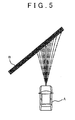
FIG. 5] FIG. 5 is a view showing an example in which there is no avoidance line within the traveling range. - [
FIG. 6] FIG. 6 is a flowchart showing a procedure of providing driving support. - [
FIG. 7] FIG. 7 is a view showing a correlation between a vehicle speed and the traveling range. - [
FIG. 8] FIG. 8 is a view showing a relationship between a normal change and the vehicle speed. - Concrete embodiments of the invention will be described hereinafter on the basis of the drawings. In this case, an example in which the invention is applied to a system that makes determinations on a traveling road of a host vehicle and an obstacle and provides support for avoiding a deviation from the traveling road on which the determination is made or a collision with the obstacle will be described. Incidentally, the "support" mentioned herein is a processing that is performed at a timing when the host vehicle can avoid a solid body as the obstacle. This processing is performed earlier than a collision damage mitigation processing that is performed if a collision of the vehicle with the obstacle is unavoidable. Besides, the configuration that will be described in each of the following embodiments of the invention indicates a mode of carrying out the invention, and does not limit the configuration of the invention.
- First of all, the first embodiment of the invention will be described on the basis of
FIGS. 1 to 6 .FIG. 1 is a block diagram functionally showing the configuration of a vehicular driving support system to which the invention is applied. As shown inFIG. 1 , a vehicle is mounted with a control unit (an ECU) 1 for driving support. - The
ECU 1 is an electronic control unit that is equipped with a CPU, a ROM, a RAM, a backup RAM, an I/O interface, and the like. Various sensors such as an outsideworld recognition device 2, ayaw rate sensor 3,wheel speed sensors 4, anacceleration sensor 5, abrake sensor 6, anaccelerator sensor 7, asteering angle sensor 8, asteering torque sensor 9 and the like are electrically connected to theECU 1. Output signals of those sensors are input to theECU 1. - The outside
world recognition device 2 includes at least one of a laser imaging detection and ranging unit (an LIDAR), a laser range finder (an LRF), a millimeter-wave radar, a stereo camera and the like, and detects information on a position of a host vehicle relative to a solid body that exists around the vehicle (e.g., a relative distance and a relative angle). - The
yaw rate sensor 3 is fitted to, for example, a vehicle body of the host vehicle, and outputs an electric signal that is correlated with a yaw rate that acts on the host vehicle. Thewheel speed sensors 4 are sensors that are fitted to wheels of the host vehicle respectively and output electric signals that are correlated with a traveling speed (a vehicle speed) of the vehicle respectively. Theacceleration sensor 5 outputs an electric signal that is correlated with an acceleration (a longitudinal acceleration) that acts in a longitudinal direction of the host vehicle and an acceleration (a lateral acceleration) that acts in a lateral direction of the host vehicle. - The
brake sensor 6 is fitted to, for example, a brake pedal in a vehicle interior, and outputs an electric signal that is correlated with an operation torque (a depression force) of the brake pedal. Theaccelerator sensor 7 is fitted to, for example, an accelerator pedal in the vehicle interior, and outputs an electric signal that is correlated with an operation torque (a depression force) of the accelerator pedal. Thesteering angle sensor 8 is fitted to, for example, a steering rod that is connected to a steering wheel in the vehicle interior, and outputs an electric signal that is correlated with a rotational angle (a steering angle) from a neutral position of the steering wheel. Thesteering torque sensor 9 is attached to a steering rod, and outputs an electric signal that is correlated with a torque (a steering torque) that is input to the steering wheel. - Besides, various instruments such as a
buzzer 10, adisplay device 11, an electric power steering (an EPS) 12, an electronically controlled brake (an ECB) 13 and the like are connected to theECU 1. Those various instruments are electrically controlled by theECU 1. - The
buzzer 10 is a device that is fitted in, for example, the vehicle interior and outputs a warning sound or the like. Thedisplay device 11 is a device that is fitted in, for example, the vehicle interior and displays various messages and a warning lamp. The electric power steering (the EPS) 12 is a device that assists a steering torque of the steering wheel with the aid of a torque that is generated by an electric motor. The electronically controlled brake (the ECB) 13 is a device that electrically adjusts a pressure of hydraulic oil (a brake hydraulic pressure) in a frictional brake that is provided in each of the wheels. - In order to control the various instruments with the aid of output signals of the aforementioned various sensors, the
ECU 1 has the following functions. That is, theECU 1 is equipped with a travelingroad recognition unit 100, a travelingrange estimation unit 101, asupport determination unit 102, awarning determination unit 103, acontrol determination unit 104, and a controlledvariable calculation unit 105. - The traveling
road recognition unit 100 generates information on a road (a traveling road) on which the host vehicle is to travel, on the basis of information output from the outsideworld recognition device 2. For example, the travelingroad recognition unit 100 generates information on positions of indices indicating solid bodies that can be obstacles for the host vehicle and lane borders (e.g., road indications such as white lines, yellow lines and the like, which indicate lane borders, curbstones that extend beside the lanes, guardrails, grooves, walls, solid bodies such as poles and the like, etc.) and the posture of the host vehicle with respect to those solid bodies and the lane borders (a distance, a yaw angle, and the like), in a coordinate system having an origin at which the host vehicle is located. Incidentally, the travelingroad recognition unit 100 is equivalent to the recognition means according to the invention. - The traveling
range estimation unit 101 specifies a route that is estimated to be followed by the host vehicle from now in the coordinate system that is generated by the travelingroad recognition unit 100. In this case, the travelingrange estimation unit 101 specifies a range (a traveling range) of a route on which the host vehicle is to travel in the future in a range of a driving operation to be normally performed by a driver. - Specifically, as shown in
FIG. 2 , the travelingrange estimation unit 101 acquires a current lateral acceleration Gy0 of a host vehicle A from an output signal of theacceleration sensor 5, and specifies a route a that is estimated to be followed by the host vehicle A in the case where the host vehicle A travels while maintaining the current lateral acceleration Gy0. Subsequently, the travelingrange estimation unit 101 specifies a route b1 that is estimated to be followed by the host vehicle A in the case where a normal change ΔGy is added to the current lateral acceleration Gy0 of the host vehicle A, and specifies a route b2 that is estimated to be followed by the host vehicle A in the case where the normal change ΔGy is subtracted from the current lateral acceleration Gy0 of the host vehicle A. In this case, the travelingrange estimation unit 101 may calculate a turning radius R of the host vehicle A from a value obtained by adding the normal change ΔGy to the current lateral acceleration Gy0 or a value obtained by subtracting the normal change ΔGy from the current lateral acceleration Gy0, and specify the routes b1 and b2 on the basis of the calculated turning radius R. Incidentally, the turning radius R can be obtained by dividing a vehicle speed V by a yaw rate γ (R = V/γ), and the yaw rate γ can be obtained by dividing the lateral acceleration Gy by the vehicle speed V (γ = Gy/V). Subsequently, the travelingrange estimation unit 101 specifies a route b0 in the case where the steering angle or the lateral acceleration is changed stepwise by a certain amount, in a range (a traveling range) from the foregoing route b1 to the foregoing route b2. - It should be noted herein that the normal change ΔGy is an amount equivalent to a maximum amount of change in the lateral acceleration within a range of a driving operation that can normally be performed by the driver, and is an amount that is experimentally obtained in advance. Incidentally, if the host vehicle A is already in a turning state at the moment (|Gy0| > 0), an absolute value (|Gy0±ΔGyl) of the value that is obtained by adding the normal change ΔGy to the current lateral acceleration Gy0 or subtracting the normal change ΔGy from the current lateral acceleration Gy0 may become larger than a maximum lateral acceleration (e.g., 0.2 G to 0.3 G) that can be generated through the normal driving operation by the driver. In consequence, the magnitude of the normal change ΔGy may be limited such that the absolute value of the value that is obtained by adding the normal change ΔGy to the current lateral acceleration Gy0 or subtracting the normal change ΔGy from the current lateral acceleration Gy0 becomes equal to or smaller than the maximum lateral acceleration.
- Besides, in specifying the traveling range, the traveling
range estimation unit 101 may set, as the routes b1 and b2, routes that are estimated to be followed by the host vehicle in the case where the host vehicle travels at the maximum lateral acceleration. For example, as shown inFIG. 3 , the travelingrange estimation unit 101 may set, as the route b1, a route that is estimated to be followed by the host vehicle in the case where the host vehicle travels while making a right turn at the maximum lateral acceleration, and set, as the route b2, a route that is followed by the host vehicle in the case where the host vehicle travels while making a left turn at the maximum lateral acceleration. - Subsequently, the
support determination unit 102 determines whether to provide driving support or not, on the basis of the information generated by the travelingroad recognition unit 100 and the traveling range estimated by the travelingrange estimation unit 101. Specifically, as shown inFIG. 4 , if there is a route (an avoidance line) E that allows a solid body B to be avoided within the traveling range, thesupport determination unit 102 prohibits driving support from being provided. On the other hand, as shown inFIG. 5 , if there is no avoidance line, thesupport determination unit 102 permits driving support to be provided. - If the
support determination unit 102 permits driving support to be provided, thewarning determination unit 103 warns the driver by ringing thebuzzer 10, displaying a warning message or a warning lamp by thedisplay device 11, etc. For example, if thesupport determination unit 102 permits driving support to be provided (if there ceases to be an avoidance line in the traveling range), thewarning determination unit 103 may immediately ring thebuzzer 10 or cause thedisplay device 11 to display the warning message or the warning lamp. - Besides, as soon as the distance between the host vehicle and the solid body becomes equal to or shorter than a predetermined distance as to a route on which the distance between the host vehicle and the solid body is longest among routes included in the traveling range, the
warning determination unit 103 may ring thebuzzer 10, or cause thedisplay device 11 to display the warning message or the warning lamp. Furthermore, thewarning determination unit 103 may calculate a time required for the host vehicle A to reach the solid body B as to the route on which the distance between the host vehicle and the solid body is longest, and ring thebuzzer 10 or cause thedisplay device 11 to display the warning message or the warning lamp as soon as the calculation result becomes equal to or shorter than a predetermined time. In this manner, if a timing at which thebuzzer 10 is rung, or a timing at which the warning message or the warning lamp is displayed by thedisplay device 11 is determined with respect to the route on which the distance between the host vehicle and the solid body is longest, those timings can be made as late as possible. As a result, driving support can be provided without making the driver feel troubled. - It should be noted herein that the foregoing predetermined distance or the foregoing predetermined time may be changed in accordance with an output signal of the
yaw rate sensor 3 or output signals of thewheel speed sensors 6. For example, the predetermined distance or the predetermined time may be set longer when the vehicle speed is high than when the vehicle speed is low. Besides, the predetermined distance or the predetermined time may be set longer when the yaw rate is large than when the yaw rate is small. - Incidentally, it is also appropriate to set the lengths of the respective routes included in the traveling range to the predetermined distance, and ring the
buzzer 10 or cause thedisplay device 11 to display the warning message or the warning lamp as soon as all the routes within the traveling range interfere with the solid body. Besides, the method of warning the driver is not limited to the method of ringing thebuzzer 10 or the method of causing thedisplay device 11 to display the warning message or the warning lamp. For example, a method of intermittently changing the fastening torque of a seat belt may be adopted. - If the
support determination unit 102 permits the driving support processing to be performed, thecontrol determination unit 104 determines timings at which the electric power steering (the EPS) 12 and the electronically controlled brake (the ECB) 13 are operated, in order to avoid a collision of the host vehicle with the solid body. - Specifically, the
control determination unit 104 may operate the electric power steering (the EPS) 12 and the electronically controlled brake (the ECB) 13 as soon as the distance between the host vehicle and the solid body becomes equal to or shorter than a predetermined distance as to the route on which the distance between the host vehicle and the solid body is longest, among the routes included in the traveling range. Besides, thecontrol determination unit 104 may calculate a time required for the host vehicle to reach the solid body as to the route on which the distance between the host vehicle and the solid body is longest, among the routes included in the traveling range, and operate the electric power steering (the EPS) 12 and the electronically controlled brake (the ECB) 13 as soon as the calculation result becomes equal to or shorter than a predetermined time. - In this manner, if the timings at which the electric power steering (the EPS) 12 and the electronically controlled brake (the ECB) 13 are operated are determined with respect to the route on which the distance between the host vehicle and the solid body is longest, it is possible to make those timings as late as possible. As a result, driving support can be provided without making the driver feel troubled.
- Incidentally, it is also appropriate to set the lengths of the respective routes included in the traveling range to the predetermined distance, and operate the electric power steering (the EPS) 12 and the electronically controlled brake (the ECB) 13 as soon as all the routes in the traveling range interfere with the solid body.
- The predetermined distance and predetermined time that are used by the
control determination unit 104 may be changed in accordance with the vehicle speed and the yaw rate, as is the case with the predetermined distance and predetermined time that are used by thewarning determination unit 103, but are set equal to or shorter than the predetermined distance and predetermined time that are used by thewarning determination unit 103, respectively. - When the
control determination unit 104 determines the timings at which the electric power steering (the EPS) 12 and the electronically controlled brake (the ECB) 13 are operated, the controlledvariable calculation unit 105 calculates controlled variables of the electric power steering (the EPS) 12 and the electronically controlled brake (the ECB) 13, and operates the electric power steering (the EPS) 12 and the electronically controlled brake (the ECB) 13 in accordance with the calculated controlled variables and the timings on which the determinations are made by thecontrol determination unit 104. - For example, the controlled
variable calculation unit 105 calculates a target yaw rate needed to avoid a collision of the host vehicle with the solid body. Subsequently, the controlledvariable calculation unit 105 determines a controlled variable (a steering torque) of the electric power steering (the EPS) 12 and a controlled variable (a brake hydraulic pressure) of the electronically controlled brake (the ECB) 13 such that an actual yaw rate of the host vehicle (an output signal of the yaw rate sensor 3) coincides with the target yaw rate. In this case, a relationship between the target yaw rate and the steering torque and a relationship between the target yaw rate and the brake hydraulic pressure may be mapped in advance. - Incidentally, the method of decelerating the vehicle is not limited to the method of operating the frictional brake by the electronically controlled brake (the ECB) 13. A method of converting (regenerating) kinetic energy of the vehicle into electric energy, or a method of changing the speed ratio of a transmission to cause an increase in engine brake may be employed. Besides, the method of changing the yaw rate of the vehicle is not limited to the method of changing the steering angle by the electric power steering (the EPS) 12. A method of applying different brake hydraulic pressures to the right and left wheels of the host vehicle respectively may be employed.
- It should be noted herein that the foregoing traveling
range estimation unit 101, the foregoingsupport determination unit 102, the foregoingwarning determination unit 103, the foregoingcontrol determination unit 104, and the foregoing controlledvariable calculation unit 105 are equivalent to the support means according to the invention. - A procedure of providing driving support in this embodiment of the invention will be described hereinafter with reference to
FIG. 6. FIG. 6 is a processing routine that is repeatedly executed by theECU 1. This processing routine is stored in advance in a ROM or the like of theECU 1. - In the processing routine of
FIG. 6 , first of all in S101, theECU 1 generates information on a traveling road on which the host vehicle is to travel in the future (traveling road information), on the basis of an output signal of the outsideworld recognition device 2. That is, theECU 1 generates information on position coordinates and sizes of a solid body that can be an obstacle of the host vehicle and an index indicating a lane border in a coordinate system having an origin where the host vehicle is located, and generates information on the posture of the host vehicle with respect to the solid body and the lane border. - In S102, the
ECU 1 determines, on the basis of the traveling road information generated in the S101, whether or not there is a solid body as an obstacle on a path of the host vehicle. The "path" mentioned herein is a route that is estimated to be followed by the host vehicle in the case where the host vehicle travels while maintaining the current lateral acceleration Gy0. If the result of the determination in S102 is negative, theECU 1 temporarily ends the execution of the present routine. On the other hand, if the result of the determination in S102 is positive, theECU 1 proceeds to S103. - In S103, the
ECU 1 reads the output signal (the lateral acceleration of the host vehicle at the moment) Gy0 of theacceleration sensor 5, and estimates a traveling range of the host vehicle with respect to the read lateral acceleration Gy0. That is, as stated in the description of the foregoingFIG. 2 , theECU 1 specifies the routes b1 and b2 by adding the normal change ΔGy to the lateral acceleration Gy0 at the moment and subtracting the normal change ΔGy from the lateral acceleration Gy0 at the moment. Subsequently, theECU 1 specifies the route b0 in the case where the steering angle or the lateral acceleration is changed stepwise by a certain amount in the range from the route b1 to the route b2. - In S104, the
ECU 1 compares the position of the solid body in the coordinate system generated in the S101 with the traveling range estimated in the S103, and determines whether or not there is an avoidance line that allows the solid body to be avoided within the traveling range. In other words, theECU 1 determines whether or not a collision of the host vehicle with the solid body can be avoided through the performance of the normal driving operation by the driver. - If the result of the determination in the S104 is positive, the
ECU 1 ends the execution of the present routine without providing driving support. On the other hand, if the result of the determination in the S104 is negative, theECU 1 proceeds to S105. - In S105, the
ECU 1 provides driving support with the aid of thebuzzer 10 or thedisplay device 11, or provides driving support with the aid of the electric power steering (the EPS) 12 and/or the electronically controlled brake (the ECB) 13. - According to the embodiment of the invention described above, if a collision of the host vehicle with the solid body can be avoided through the performance of the normal driving operation by the driver, driving support is not provided. Therefore, driving support is stopped from being provided despite the driver's intention of performing the normal driving operation.
- Incidentally, according to the driving support system of this embodiment of the invention, even in the case where the driver does not intend to perform the normal driving operation (e.g., in the case where the consciousness level of the driver has fallen, the case where the driver looks off, etc.), driving support is not provided as long as there is an avoidance line within the traveling range. However, if the host vehicle approaches the solid body, there ceases to be an avoidance line within the traveling range, and hence driving support is provided before the host vehicle collides with the solid body. In consequence, even in the case where the driver does not perform the normal driving operation, a collision of the host vehicle with the solid body can be avoided.
- Besides, in this embodiment of the invention, the lateral acceleration is used as a parameter indicating the movement amount of the host vehicle. However, it is also possible to use a yaw rate, a lateral G, a cornering force, or the like. However, it is preferable to use a parameter that is correlated with the yaw rate and the vehicle speed, such as the lateral acceleration or the lateral G. The lateral acceleration and the lateral G increase as the yaw rate increases, and increase as the vehicle speed increases. In consequence, in the case where the lateral acceleration or the lateral G is used as a parameter indicating the movement amount of the host vehicle, the traveling range that is estimated by the traveling
range estimation unit 101 is narrower when the vehicle speed is high ((a) inFIG. 7 ) than when the vehicle speed is low ((b) inFIG. 7 ), as shown inFIG. 7 . As a result, the timing at which there ceases to be an avoidance line within the traveling range (the timing at which driving support is provided) is earlier when the vehicle speed is high than when the vehicle speed is low. In consequence, even in the case where the traveling speed of the host vehicle is high, a collision of the host vehicle with the solid body can be more reliably avoided. - Next, the second embodiment of the invention will be described on the basis of
FIG. 8 . In this case, configurational details different from those of the foregoing first embodiment of the invention will be described, and the description of similar configurational details will be omitted. - The difference between the foregoing first embodiment of the invention and this embodiment of the invention consists in that the magnitude of the normal change ΔGy is changed in accordance with the vehicle speed. In general, the magnitude of the lateral acceleration that is permitted when the driver performs a normal driving operation is larger in a low speed range than in a high speed range.
- Thus, as shown in
FIG. 8 , the normal change ΔGy may increase as the vehicle speed decreases in a region where the vehicle speed is lower than a specific vehicle speed V0, and may be fixed to a constant value in a region where the vehicle speed is equal to or higher than the specific vehicle speed V0. It should be noted herein that the specific vehicle speed V0 is a value that is statistically obtained in advance. - If the normal change ΔGy is thus changed in accordance with the vehicle speed, the number of opportunities in which driving support is provided against the intention of the driver when the host vehicle travels at a low speed can be reduced, and the timing at which driving support is provided can be made as late as possible. Besides, it is also possible to avoid a situation where the timing at which driving support is provided becomes late when the host vehicle travels at a high speed.
-
- 1
- ECU
- 2
- OUTSIDE WORLD RECOGNITION DEVICE
- 3
- YAW RATE SENSOR
- 4
- WHEEL SPEED SENSORS
- 5
- ACCELERATION SENSOR
- 6
- BRAKE SENSOR
- 7
- ACCELERATOR SENSOR
- 8
- STEERING ANGLE SENSOR
- 9
- STEERING TORQUE SENSOR
- 10
- BUZZER
- 11
- DISPLAY DEVICE
- 12
- ELECTRIC POWER STEERING
- 13
- ELECTRONICALLY CONTROLLED BRAKE
- 100
- TRAVELING ROAD RECOGNITION UNIT
- 101
- TRAVELING RANGE ESTIMATION UNIT
- 102
- SUPPORT DETERMINATION UNIT
- 103
- WARNING DETERMINATION UNIT
- 104
- CONTROL DETERMINATION UNIT
- 105
- CONTROLLED VARIABLE CALCULATION UNIT
Claims (5)
- A vehicular driving support system comprising:recognition means for recognizing a solid body that exists around a host vehicle;acquisition means for acquiring a current movement amount of the host vehicle; andsupport means for providing support for avoiding a collision with the solid body on a condition that there be no avoidance line as a route that allows a collision with the solid body recognized by the recognition means to be avoided in a traveling range as a range of a route on which the host vehicle is to travel, if a change in a movement amount that is produced within a range of a driving operation to be normally performed by a driver is increased or reduced from the movement amount acquired by the acquisition means.
- The vehicular driving support system according to claim 1, wherein
the change is made larger when a traveling speed of the host vehicle is low than when the traveling speed of the host vehicle is high. - The vehicular driving support system according to claim 1 or 2, wherein
the movement amount is a parameter that makes the traveling range narrower when the traveling speed of the host vehicle is high than when the traveling speed of the host vehicle is low. - The vehicular driving support system according to claim 3, wherein
the movement amount is a parameter that is correlated with an acceleration in a lateral direction of the host vehicle. - The vehicular driving support system according to any one of claims 1 to 4, wherein
the support means provides support for avoiding a collision with the solid body if a length of a longest one of routes included in the traveling range becomes equal to or shorter than a threshold in a case where there is no avoidance line in the traveling range.
Applications Claiming Priority (1)
| Application Number | Priority Date | Filing Date | Title |
|---|---|---|---|
| PCT/JP2011/071888 WO2013046298A1 (en) | 2011-09-26 | 2011-09-26 | Vehicle driving assistance system |
Publications (3)
| Publication Number | Publication Date |
|---|---|
| EP2763119A1 true EP2763119A1 (en) | 2014-08-06 |
| EP2763119A4 EP2763119A4 (en) | 2016-08-10 |
| EP2763119B1 EP2763119B1 (en) | 2019-04-03 |
Family
ID=47994416
Family Applications (1)
| Application Number | Title | Priority Date | Filing Date |
|---|---|---|---|
| EP11873132.2A Active EP2763119B1 (en) | 2011-09-26 | 2011-09-26 | Vehicle driving assistance system |
Country Status (9)
| Country | Link |
|---|---|
| US (1) | US9196162B2 (en) |
| EP (1) | EP2763119B1 (en) |
| JP (1) | JP5768891B2 (en) |
| KR (1) | KR20140051444A (en) |
| CN (1) | CN103827940B (en) |
| BR (1) | BR112014002752B1 (en) |
| CA (1) | CA2843835A1 (en) |
| RU (1) | RU2570191C2 (en) |
| WO (1) | WO2013046298A1 (en) |
Cited By (2)
| Publication number | Priority date | Publication date | Assignee | Title |
|---|---|---|---|---|
| EP2830031A4 (en) * | 2012-03-19 | 2016-08-10 | Toyota Motor Co Ltd | DEVICE FOR ASSISTING THE AVOIDANCE OF COLLISIONS |
| EP4249336A1 (en) * | 2022-03-24 | 2023-09-27 | Toyota Jidosha Kabushiki Kaisha | Driving assistance device, driving assistance method, and storage medium |
Families Citing this family (12)
| Publication number | Priority date | Publication date | Assignee | Title |
|---|---|---|---|---|
| US10421398B2 (en) | 2012-11-21 | 2019-09-24 | Toyota Jidosha Kabushiki Kaisha | Driving-assistance device and driving-assistance method |
| US9669826B2 (en) | 2012-11-21 | 2017-06-06 | Toyota Jidosha Kabushiki Kaisha | Driving-assistance device and driving-assistance method |
| JP6447639B2 (en) * | 2015-01-05 | 2019-01-09 | 日産自動車株式会社 | Target route generation device and travel control device |
| KR102386317B1 (en) * | 2015-08-12 | 2022-04-13 | 현대모비스 주식회사 | Vehicle and collision avoidance method for the same |
| DE102016109856A1 (en) * | 2016-05-30 | 2017-11-30 | Valeo Schalter Und Sensoren Gmbh | Method for avoiding a collision of a motor vehicle with an object based on a maximum predefinable wheel steering angle, driver assistance system and motor vehicle |
| JP6972744B2 (en) * | 2017-08-01 | 2021-11-24 | トヨタ自動車株式会社 | Driving support device |
| KR102334158B1 (en) * | 2017-10-30 | 2021-12-02 | 현대모비스 주식회사 | Autonomous emergency braking apparatus and control method thereof |
| CN108196546A (en) * | 2018-01-03 | 2018-06-22 | 驭势(上海)汽车科技有限公司 | The security monitor system and method for intelligent driving vehicle |
| CN109353339B (en) * | 2018-09-29 | 2020-06-26 | 中国铁建重工集团股份有限公司 | Vehicle navigation method and system |
| JP7343837B2 (en) * | 2019-10-03 | 2023-09-13 | トヨタ自動車株式会社 | Driving support device |
| CN112193243B (en) * | 2020-10-20 | 2022-01-28 | 河北工业大学 | Multi-steering mode control method based on obstacle avoidance system |
| EP4082853A1 (en) * | 2021-04-28 | 2022-11-02 | KNORR-BREMSE Systeme für Nutzfahrzeuge GmbH | Evaluation apparatus for evaluating a trajectory hypothesis for a vehicle |
Family Cites Families (20)
| Publication number | Priority date | Publication date | Assignee | Title |
|---|---|---|---|---|
| JP3031758B2 (en) * | 1991-08-22 | 2000-04-10 | マツダ株式会社 | Automatic vehicle steering system |
| JPH07149193A (en) | 1993-11-30 | 1995-06-13 | Toyota Motor Corp | Vehicle collision prevention device |
| JP3319984B2 (en) * | 1997-07-09 | 2002-09-03 | 本田技研工業株式会社 | Vehicle collision avoidance device |
| SE512695C2 (en) * | 1998-07-02 | 2000-05-02 | Volvo Lastvagnar Ab | Auxiliary braking system for motor vehicle, especially heavy goods vehicles, comprises hydrodynamic retarder coupled to vehicle gearbox output |
| DE102004008894A1 (en) * | 2004-02-24 | 2005-09-08 | Robert Bosch Gmbh | Safety system for a means of transportation and related method |
| JP4333639B2 (en) * | 2005-06-13 | 2009-09-16 | 株式会社豊田中央研究所 | Obstacle avoidance control device and obstacle avoidance control program |
| JP4446984B2 (en) * | 2006-07-10 | 2010-04-07 | 本田技研工業株式会社 | Vehicle travel safety device |
| DE102006042666A1 (en) * | 2006-09-12 | 2008-03-27 | Robert Bosch Gmbh | Method for avoiding or mitigating the collision of a vehicle with at least one object |
| JP2008242544A (en) | 2007-03-26 | 2008-10-09 | Hitachi Ltd | Collision avoidance apparatus and method |
| JP4706654B2 (en) * | 2007-03-27 | 2011-06-22 | トヨタ自動車株式会社 | Collision avoidance device |
| RU2388057C2 (en) * | 2007-10-15 | 2010-04-27 | Андрей Станиславович Гурин | Method of ensuring active safety for transportation vehicles moving in file |
| JP5043760B2 (en) | 2008-06-17 | 2012-10-10 | 日産自動車株式会社 | Vehicle obstacle avoidance support apparatus and vehicle obstacle avoidance support method |
| JP2010179843A (en) | 2009-02-06 | 2010-08-19 | Nissan Motor Co Ltd | Device and method for supporting driving operation |
| DE102009012226A1 (en) * | 2009-03-07 | 2010-09-09 | Daimler Ag | Method for avoiding or reducing collision of vehicle with e.g. road user, involves determining trigger load, where trigger load depends upon maximum transverse acceleration parameter that depends upon velocity of vehicle |
| DE102009020649A1 (en) * | 2009-05-08 | 2010-11-18 | Daimler Ag | Method for avoiding collision of motor vehicle towards obstacle, involves producing warning for driver of vehicle optically, acoustically and/or haptically according to different escalation stages when time interval limits are reached |
| JP2011005893A (en) * | 2009-06-23 | 2011-01-13 | Nissan Motor Co Ltd | Vehicular travel control device, and vehicular travel control method |
| JP2011150577A (en) * | 2010-01-22 | 2011-08-04 | Toyota Motor Corp | Alarm device |
| JP5426427B2 (en) * | 2010-02-19 | 2014-02-26 | 日立オートモティブシステムズ株式会社 | Driving support device |
| JP5463971B2 (en) * | 2010-03-10 | 2014-04-09 | 日産自動車株式会社 | Mobile body travel route generation device |
| JP5657997B2 (en) * | 2010-10-29 | 2015-01-21 | アイシン精機株式会社 | Vehicle lateral motion control device |
-
2011
- 2011-09-26 EP EP11873132.2A patent/EP2763119B1/en active Active
- 2011-09-26 JP JP2013535658A patent/JP5768891B2/en active Active
- 2011-09-26 RU RU2014110658/11A patent/RU2570191C2/en active
- 2011-09-26 CA CA2843835A patent/CA2843835A1/en not_active Abandoned
- 2011-09-26 WO PCT/JP2011/071888 patent/WO2013046298A1/en not_active Ceased
- 2011-09-26 BR BR112014002752-8A patent/BR112014002752B1/en active IP Right Grant
- 2011-09-26 CN CN201180073659.4A patent/CN103827940B/en active Active
- 2011-09-26 US US14/346,793 patent/US9196162B2/en active Active
- 2011-09-26 KR KR1020147007462A patent/KR20140051444A/en not_active Ceased
Cited By (3)
| Publication number | Priority date | Publication date | Assignee | Title |
|---|---|---|---|---|
| EP2830031A4 (en) * | 2012-03-19 | 2016-08-10 | Toyota Motor Co Ltd | DEVICE FOR ASSISTING THE AVOIDANCE OF COLLISIONS |
| EP4249336A1 (en) * | 2022-03-24 | 2023-09-27 | Toyota Jidosha Kabushiki Kaisha | Driving assistance device, driving assistance method, and storage medium |
| EP4360975A3 (en) * | 2022-03-24 | 2024-07-24 | Toyota Jidosha Kabushiki Kaisha | Driving assistance device, driving assistance method, and storage medium |
Also Published As
| Publication number | Publication date |
|---|---|
| KR20140051444A (en) | 2014-04-30 |
| EP2763119A4 (en) | 2016-08-10 |
| BR112014002752A2 (en) | 2017-02-21 |
| US9196162B2 (en) | 2015-11-24 |
| US20140257593A1 (en) | 2014-09-11 |
| CN103827940B (en) | 2016-04-06 |
| JP5768891B2 (en) | 2015-08-26 |
| EP2763119B1 (en) | 2019-04-03 |
| WO2013046298A1 (en) | 2013-04-04 |
| CN103827940A (en) | 2014-05-28 |
| RU2014110658A (en) | 2015-11-10 |
| JPWO2013046298A1 (en) | 2015-03-26 |
| RU2570191C2 (en) | 2015-12-10 |
| CA2843835A1 (en) | 2013-04-04 |
| BR112014002752B1 (en) | 2021-06-08 |
Similar Documents
| Publication | Publication Date | Title |
|---|---|---|
| EP2763119B1 (en) | Vehicle driving assistance system | |
| US9105190B2 (en) | Driving support system for a vehicle | |
| EP2623387B1 (en) | Driving support apparatus and driving support method | |
| US9852633B2 (en) | Travel assist apparatus and travel assist method | |
| US9043045B2 (en) | Travel assist apparatus and travel assist method | |
| US10421398B2 (en) | Driving-assistance device and driving-assistance method | |
| JP5716343B2 (en) | Vehicle object recognition system | |
| JP5516301B2 (en) | Vehicle runway determination system | |
| EP2763122A1 (en) | Vehicle driving assistance system | |
| EP2654026A1 (en) | Travel assistance device, travel assistance method, and vehicle | |
| JP2012079118A (en) | Drive-supporting apparatus and drive-supporting method | |
| JP2012079116A (en) | Drive-supporting apparatus and drive-supporting method | |
| JP2012084038A (en) | Vehicle driving support system | |
| US20140012491A1 (en) | Traveling support apparatus and traveling support method | |
| JP5867368B2 (en) | Vehicle driving support apparatus and driving support method | |
| JP5761088B2 (en) | Vehicle driving support system | |
| JP2012232639A (en) | Driving support device and method | |
| JPWO2013046293A1 (en) | Vehicle driving support system |
Legal Events
| Date | Code | Title | Description |
|---|---|---|---|
| PUAI | Public reference made under article 153(3) epc to a published international application that has entered the european phase |
Free format text: ORIGINAL CODE: 0009012 |
|
| 17P | Request for examination filed |
Effective date: 20140317 |
|
| AK | Designated contracting states |
Kind code of ref document: A1 Designated state(s): AL AT BE BG CH CY CZ DE DK EE ES FI FR GB GR HR HU IE IS IT LI LT LU LV MC MK MT NL NO PL PT RO RS SE SI SK SM TR |
|
| DAX | Request for extension of the european patent (deleted) | ||
| RA4 | Supplementary search report drawn up and despatched (corrected) |
Effective date: 20160707 |
|
| RIC1 | Information provided on ipc code assigned before grant |
Ipc: B60R 21/00 20060101ALI20160701BHEP Ipc: B60W 30/08 20120101ALI20160701BHEP Ipc: G06K 9/00 20060101ALI20160701BHEP Ipc: B62D 15/02 20060101ALI20160701BHEP Ipc: G08G 1/16 20060101AFI20160701BHEP |
|
| GRAP | Despatch of communication of intention to grant a patent |
Free format text: ORIGINAL CODE: EPIDOSNIGR1 |
|
| STAA | Information on the status of an ep patent application or granted ep patent |
Free format text: STATUS: GRANT OF PATENT IS INTENDED |
|
| INTG | Intention to grant announced |
Effective date: 20181031 |
|
| GRAS | Grant fee paid |
Free format text: ORIGINAL CODE: EPIDOSNIGR3 |
|
| GRAA | (expected) grant |
Free format text: ORIGINAL CODE: 0009210 |
|
| STAA | Information on the status of an ep patent application or granted ep patent |
Free format text: STATUS: THE PATENT HAS BEEN GRANTED |
|
| AK | Designated contracting states |
Kind code of ref document: B1 Designated state(s): AL AT BE BG CH CY CZ DE DK EE ES FI FR GB GR HR HU IE IS IT LI LT LU LV MC MK MT NL NO PL PT RO RS SE SI SK SM TR |
|
| REG | Reference to a national code |
Ref country code: GB Ref legal event code: FG4D |
|
| REG | Reference to a national code |
Ref country code: CH Ref legal event code: EP Ref country code: AT Ref legal event code: REF Ref document number: 1116694 Country of ref document: AT Kind code of ref document: T Effective date: 20190415 |
|
| REG | Reference to a national code |
Ref country code: DE Ref legal event code: R096 Ref document number: 602011057851 Country of ref document: DE |
|
| REG | Reference to a national code |
Ref country code: IE Ref legal event code: FG4D |
|
| REG | Reference to a national code |
Ref country code: DE Ref legal event code: R084 Ref document number: 602011057851 Country of ref document: DE |
|
| REG | Reference to a national code |
Ref country code: GB Ref legal event code: 746 Effective date: 20190716 Ref country code: NL Ref legal event code: MP Effective date: 20190403 |
|
| REG | Reference to a national code |
Ref country code: LT Ref legal event code: MG4D |
|
| REG | Reference to a national code |
Ref country code: AT Ref legal event code: MK05 Ref document number: 1116694 Country of ref document: AT Kind code of ref document: T Effective date: 20190403 |
|
| PG25 | Lapsed in a contracting state [announced via postgrant information from national office to epo] |
Ref country code: NL Free format text: LAPSE BECAUSE OF FAILURE TO SUBMIT A TRANSLATION OF THE DESCRIPTION OR TO PAY THE FEE WITHIN THE PRESCRIBED TIME-LIMIT Effective date: 20190403 |
|
| PG25 | Lapsed in a contracting state [announced via postgrant information from national office to epo] |
Ref country code: NO Free format text: LAPSE BECAUSE OF FAILURE TO SUBMIT A TRANSLATION OF THE DESCRIPTION OR TO PAY THE FEE WITHIN THE PRESCRIBED TIME-LIMIT Effective date: 20190703 Ref country code: AL Free format text: LAPSE BECAUSE OF FAILURE TO SUBMIT A TRANSLATION OF THE DESCRIPTION OR TO PAY THE FEE WITHIN THE PRESCRIBED TIME-LIMIT Effective date: 20190403 Ref country code: FI Free format text: LAPSE BECAUSE OF FAILURE TO SUBMIT A TRANSLATION OF THE DESCRIPTION OR TO PAY THE FEE WITHIN THE PRESCRIBED TIME-LIMIT Effective date: 20190403 Ref country code: ES Free format text: LAPSE BECAUSE OF FAILURE TO SUBMIT A TRANSLATION OF THE DESCRIPTION OR TO PAY THE FEE WITHIN THE PRESCRIBED TIME-LIMIT Effective date: 20190403 Ref country code: SE Free format text: LAPSE BECAUSE OF FAILURE TO SUBMIT A TRANSLATION OF THE DESCRIPTION OR TO PAY THE FEE WITHIN THE PRESCRIBED TIME-LIMIT Effective date: 20190403 Ref country code: PT Free format text: LAPSE BECAUSE OF FAILURE TO SUBMIT A TRANSLATION OF THE DESCRIPTION OR TO PAY THE FEE WITHIN THE PRESCRIBED TIME-LIMIT Effective date: 20190803 Ref country code: HR Free format text: LAPSE BECAUSE OF FAILURE TO SUBMIT A TRANSLATION OF THE DESCRIPTION OR TO PAY THE FEE WITHIN THE PRESCRIBED TIME-LIMIT Effective date: 20190403 Ref country code: LT Free format text: LAPSE BECAUSE OF FAILURE TO SUBMIT A TRANSLATION OF THE DESCRIPTION OR TO PAY THE FEE WITHIN THE PRESCRIBED TIME-LIMIT Effective date: 20190403 Ref country code: CZ Free format text: LAPSE BECAUSE OF FAILURE TO SUBMIT A TRANSLATION OF THE DESCRIPTION OR TO PAY THE FEE WITHIN THE PRESCRIBED TIME-LIMIT Effective date: 20190403 |
|
| PG25 | Lapsed in a contracting state [announced via postgrant information from national office to epo] |
Ref country code: BG Free format text: LAPSE BECAUSE OF FAILURE TO SUBMIT A TRANSLATION OF THE DESCRIPTION OR TO PAY THE FEE WITHIN THE PRESCRIBED TIME-LIMIT Effective date: 20190703 Ref country code: PL Free format text: LAPSE BECAUSE OF FAILURE TO SUBMIT A TRANSLATION OF THE DESCRIPTION OR TO PAY THE FEE WITHIN THE PRESCRIBED TIME-LIMIT Effective date: 20190403 Ref country code: RS Free format text: LAPSE BECAUSE OF FAILURE TO SUBMIT A TRANSLATION OF THE DESCRIPTION OR TO PAY THE FEE WITHIN THE PRESCRIBED TIME-LIMIT Effective date: 20190403 Ref country code: LV Free format text: LAPSE BECAUSE OF FAILURE TO SUBMIT A TRANSLATION OF THE DESCRIPTION OR TO PAY THE FEE WITHIN THE PRESCRIBED TIME-LIMIT Effective date: 20190403 Ref country code: GR Free format text: LAPSE BECAUSE OF FAILURE TO SUBMIT A TRANSLATION OF THE DESCRIPTION OR TO PAY THE FEE WITHIN THE PRESCRIBED TIME-LIMIT Effective date: 20190704 |
|
| PG25 | Lapsed in a contracting state [announced via postgrant information from national office to epo] |
Ref country code: AT Free format text: LAPSE BECAUSE OF FAILURE TO SUBMIT A TRANSLATION OF THE DESCRIPTION OR TO PAY THE FEE WITHIN THE PRESCRIBED TIME-LIMIT Effective date: 20190403 Ref country code: IS Free format text: LAPSE BECAUSE OF FAILURE TO SUBMIT A TRANSLATION OF THE DESCRIPTION OR TO PAY THE FEE WITHIN THE PRESCRIBED TIME-LIMIT Effective date: 20190803 |
|
| REG | Reference to a national code |
Ref country code: DE Ref legal event code: R097 Ref document number: 602011057851 Country of ref document: DE |
|
| PG25 | Lapsed in a contracting state [announced via postgrant information from national office to epo] |
Ref country code: RO Free format text: LAPSE BECAUSE OF FAILURE TO SUBMIT A TRANSLATION OF THE DESCRIPTION OR TO PAY THE FEE WITHIN THE PRESCRIBED TIME-LIMIT Effective date: 20190403 Ref country code: SK Free format text: LAPSE BECAUSE OF FAILURE TO SUBMIT A TRANSLATION OF THE DESCRIPTION OR TO PAY THE FEE WITHIN THE PRESCRIBED TIME-LIMIT Effective date: 20190403 Ref country code: EE Free format text: LAPSE BECAUSE OF FAILURE TO SUBMIT A TRANSLATION OF THE DESCRIPTION OR TO PAY THE FEE WITHIN THE PRESCRIBED TIME-LIMIT Effective date: 20190403 Ref country code: DK Free format text: LAPSE BECAUSE OF FAILURE TO SUBMIT A TRANSLATION OF THE DESCRIPTION OR TO PAY THE FEE WITHIN THE PRESCRIBED TIME-LIMIT Effective date: 20190403 |
|
| PLBE | No opposition filed within time limit |
Free format text: ORIGINAL CODE: 0009261 |
|
| STAA | Information on the status of an ep patent application or granted ep patent |
Free format text: STATUS: NO OPPOSITION FILED WITHIN TIME LIMIT |
|
| PG25 | Lapsed in a contracting state [announced via postgrant information from national office to epo] |
Ref country code: IT Free format text: LAPSE BECAUSE OF FAILURE TO SUBMIT A TRANSLATION OF THE DESCRIPTION OR TO PAY THE FEE WITHIN THE PRESCRIBED TIME-LIMIT Effective date: 20190403 Ref country code: SM Free format text: LAPSE BECAUSE OF FAILURE TO SUBMIT A TRANSLATION OF THE DESCRIPTION OR TO PAY THE FEE WITHIN THE PRESCRIBED TIME-LIMIT Effective date: 20190403 |
|
| 26N | No opposition filed |
Effective date: 20200106 |
|
| PG25 | Lapsed in a contracting state [announced via postgrant information from national office to epo] |
Ref country code: TR Free format text: LAPSE BECAUSE OF FAILURE TO SUBMIT A TRANSLATION OF THE DESCRIPTION OR TO PAY THE FEE WITHIN THE PRESCRIBED TIME-LIMIT Effective date: 20190403 |
|
| PG25 | Lapsed in a contracting state [announced via postgrant information from national office to epo] |
Ref country code: SI Free format text: LAPSE BECAUSE OF FAILURE TO SUBMIT A TRANSLATION OF THE DESCRIPTION OR TO PAY THE FEE WITHIN THE PRESCRIBED TIME-LIMIT Effective date: 20190403 Ref country code: MC Free format text: LAPSE BECAUSE OF FAILURE TO SUBMIT A TRANSLATION OF THE DESCRIPTION OR TO PAY THE FEE WITHIN THE PRESCRIBED TIME-LIMIT Effective date: 20190403 |
|
| REG | Reference to a national code |
Ref country code: CH Ref legal event code: PL |
|
| PG25 | Lapsed in a contracting state [announced via postgrant information from national office to epo] |
Ref country code: LI Free format text: LAPSE BECAUSE OF NON-PAYMENT OF DUE FEES Effective date: 20190930 Ref country code: LU Free format text: LAPSE BECAUSE OF NON-PAYMENT OF DUE FEES Effective date: 20190926 Ref country code: IE Free format text: LAPSE BECAUSE OF NON-PAYMENT OF DUE FEES Effective date: 20190926 Ref country code: CH Free format text: LAPSE BECAUSE OF NON-PAYMENT OF DUE FEES Effective date: 20190930 |
|
| REG | Reference to a national code |
Ref country code: BE Ref legal event code: MM Effective date: 20190930 |
|
| PG25 | Lapsed in a contracting state [announced via postgrant information from national office to epo] |
Ref country code: BE Free format text: LAPSE BECAUSE OF NON-PAYMENT OF DUE FEES Effective date: 20190930 |
|
| PG25 | Lapsed in a contracting state [announced via postgrant information from national office to epo] |
Ref country code: CY Free format text: LAPSE BECAUSE OF FAILURE TO SUBMIT A TRANSLATION OF THE DESCRIPTION OR TO PAY THE FEE WITHIN THE PRESCRIBED TIME-LIMIT Effective date: 20190403 |
|
| PG25 | Lapsed in a contracting state [announced via postgrant information from national office to epo] |
Ref country code: MT Free format text: LAPSE BECAUSE OF FAILURE TO SUBMIT A TRANSLATION OF THE DESCRIPTION OR TO PAY THE FEE WITHIN THE PRESCRIBED TIME-LIMIT Effective date: 20190403 Ref country code: HU Free format text: LAPSE BECAUSE OF FAILURE TO SUBMIT A TRANSLATION OF THE DESCRIPTION OR TO PAY THE FEE WITHIN THE PRESCRIBED TIME-LIMIT; INVALID AB INITIO Effective date: 20110926 |
|
| PG25 | Lapsed in a contracting state [announced via postgrant information from national office to epo] |
Ref country code: MK Free format text: LAPSE BECAUSE OF FAILURE TO SUBMIT A TRANSLATION OF THE DESCRIPTION OR TO PAY THE FEE WITHIN THE PRESCRIBED TIME-LIMIT Effective date: 20190403 |
|
| P01 | Opt-out of the competence of the unified patent court (upc) registered |
Effective date: 20230427 |
|
| PGFP | Annual fee paid to national office [announced via postgrant information from national office to epo] |
Ref country code: DE Payment date: 20250730 Year of fee payment: 15 |
|
| PGFP | Annual fee paid to national office [announced via postgrant information from national office to epo] |
Ref country code: GB Payment date: 20250807 Year of fee payment: 15 |
|
| PGFP | Annual fee paid to national office [announced via postgrant information from national office to epo] |
Ref country code: FR Payment date: 20250808 Year of fee payment: 15 |