EP2763061A1 - Computer-implemented method for designing an assembly of objects in a three-dimensional scene of a system of computer-aided design - Google Patents
Computer-implemented method for designing an assembly of objects in a three-dimensional scene of a system of computer-aided design Download PDFInfo
- Publication number
- EP2763061A1 EP2763061A1 EP13305124.3A EP13305124A EP2763061A1 EP 2763061 A1 EP2763061 A1 EP 2763061A1 EP 13305124 A EP13305124 A EP 13305124A EP 2763061 A1 EP2763061 A1 EP 2763061A1
- Authority
- EP
- European Patent Office
- Prior art keywords
- computer
- design dimensions
- objects
- assembly
- design
- Prior art date
- Legal status (The legal status is an assumption and is not a legal conclusion. Google has not performed a legal analysis and makes no representation as to the accuracy of the status listed.)
- Ceased
Links
Images



Classifications
-
- G—PHYSICS
- G06—COMPUTING OR CALCULATING; COUNTING
- G06F—ELECTRIC DIGITAL DATA PROCESSING
- G06F30/00—Computer-aided design [CAD]
- G06F30/10—Geometric CAD
-
- G—PHYSICS
- G06—COMPUTING OR CALCULATING; COUNTING
- G06F—ELECTRIC DIGITAL DATA PROCESSING
- G06F30/00—Computer-aided design [CAD]
-
- G—PHYSICS
- G06—COMPUTING OR CALCULATING; COUNTING
- G06F—ELECTRIC DIGITAL DATA PROCESSING
- G06F2111/00—Details relating to CAD techniques
- G06F2111/02—CAD in a network environment, e.g. collaborative CAD or distributed simulation
Definitions
- the invention relates to the field of computers programs and systems, and more specifically to the field of computer-implemented method for designing an assembly of objects in a three-dimensional scene of a system of computer-aided design.
- This invention is related to general assembly design in which parts or objects of different design dimensions ranges are involved. This invention can be found in any program that mixes through a product structure objects of high dimension (like a 1000km road) and objects of small dimensions (like a bolt).
- Such a design dimensions range corresponds to real dimensions of objects which are comprised between a lower limit and an upper limit delimiting said dimensions range.
- CATIA Version 5 provides different design dimensions ranges of design in different objects but it is impossible to mix the objects of different design dimensions ranges to make a complete multi design dimensions ranges assembly. This drawback may lead the users to bypass it or use it in a unconventional manner.
- a scale factor in order to fit large dimension objects into a normal dimension object. For instance, using a 1:1000 scale factor, a 100km dike becomes a 100m object which can fit in a normal dimension object. Of course, the issue of mixing objects remains.
- the range of design which is the size ratio between the biggest and the smallest element, is limited by the hardware architecture of the computer.
- geometric modelers have a predefined and constant range of design for geometric objects which defines the size ratio between the biggest and the smallest element.
- a goal of the invention is to provide a computer-implemented method and a system to overcome the above mentioned problems.
- a computer-implemented method for designing an assembly of objects in a three-dimensional scene of a system of computer-aided design comprising the steps of:
- each locator comprises an axis system.
- An axis system provides not only information relative to position but additionally information relative to orientation, for example with angle values.
- a second locator is positioned relative to the first locator.
- a relative positioning allows to locate all elements or objects relatively to each other.
- different second locators are successively nested.
- the design dimensions ranges are selectable in a predefined list.
- the first design dimensions range is automatically adapted to fit the biggest object of the assembly.
- the user is sure that the biggest object can be perfectly enclosed in the dimension range.
- the first design dimensions range is as small as possible.
- the user can make his design automatically with the best adapted first design dimensions range and take benefit of the best possible accuracy.
- a computer-readable medium having computer-executable instructions to cause the computer system to perform the method for designing an assembly of objects in a three-dimensional scene as described above.
- a computer program product stored on a computer readable medium, for designing an assembly of objects in a three-dimensional scene, comprising code means for causing the system to take the steps as described above.
- an apparatus for designing an assembly of objects in a three-dimensional scene of a computer-aided system comprising means for implementing the steps as described above.
- the purpose of the present invention is to allow mixed multi-range 3D design with a precision which always fits user expectation.
- This invention is seen under different aspects.
- a first aspect is the availability of different ranges of modeling depending on the dimensions of the part or object of the assembly to design.
- the user may have the choice between, for instance:
- the computer-implemented method for designing an assembly of objects in a three-dimensional scene of a system of computer-aided design comprises:
- a part containing a locator for example an axis system, that is used to locate and position the lower dimension part.
- This mechanism can be repeated as many times as desired: the lower dimension part can define a locator in order to locate and position an even lower dimension part, and so on.
- An axis system can be used as a locator to locate a part which is not from a directly smaller design dimensions range. That means that the axis system in an Extra Large Design dimensions range part can be used to position a Normal or Small Design dimensions range part (not only a Large Design dimensions range part).
- locators there can be several locators, in the present case several axis systems, if there are several lower dimension parts to be located and assembled with the same part.
- the location is associative. If the locator position changes, the part which is positioned on this locator moves accordingly when it gets updated.
- first locator LOC1 associated with an upper design dimensions range assembly which is the Large Design dimensions range Part LDRP, comprising a first element EL1.
- locators or in other words reference and local(s) frames, comprise a respective axis system, but, alternatively, they can comprise any system for spatial positioning.
- a second locator LOC2 is associated with a Normal Design dimensions range Part NDRP, comprising two second elements EL2a and EL2b, and a third locator LOC3 is associated with a Small Design dimensions range Part SDRP, comprising a third element EL3.
- FIG 3 is illustrated an example of refinement on the design of a bridge, wherein different second locators are successively nested in a first locator LOC1.
- the first locator LOC1 is associated with a Extra Large Design dimensions range ELDR, the Earth, and a first second locator LOCI2a associated with a Large Design dimensions range LDR, a bridge, nested in the first locator LOC1, and a second second locator LOCI2b associated with a Normal Design dimensions range NDR, a section of the bridge, nested in the first second locator LOCI2a.
- This invention also proposes to transfer a part of the geometry in a given design dimensions range part to a lower or upper design dimensions range part.
- the geometry is clipped to fit into the lower design dimensions range part.
- the geometry might also need to be cleaned if there are some gaps in the geometry that would have to be filled to get a clean and valid geometry (and topology) after transfer.
- FIGS 4 to 9 illustrate an example of the method according to an aspect of the invention.
- the user can start from a first locator LOC1 associated with a Large Design dimensions range Part LDRP to make the conceptual design of a bridge, like illustrated on figure 4 .
- the user can define two second locators LOC2a and LOC2b, to locate a position two corresponding Normal Design dimensions ranges Parts NDRPa and NDRPb, and on figure 6 the user can create and position the two corresponding Normal Design dimensions ranges Parts NDRPa and NDRPb.
- Import or transfer of skeleton data from the large dimension part.
- the data are clipped and cleaned if necessary during import.
- Import mechanism works on any type of geometry (wireframe, surface, solid, mesh%) and is also associative.
- figure 9 an assembly of a large design dimensions range part LDRP and normal design dimensions ranges parts NDRPa and NDRPb.
- the geometry is cleaned so that the too small entities (the ones smaller than the precision of the upper dimension part) are removed from the resulting geometry.
- the design dimensions ranges are selectable in a predefined list.
- the first design dimensions range is adapted to fit the biggest object of the assembly.
- the first design dimensions range can be as small as possible.
- Figure 10 illustrates a computer network or similar digital processing environment in which the present invention may be implemented.
- Client computer(s)/devices CL and server computer(s) SV provide processing, storage, and input/output devices executing application programs and the like.
- Client computer(s)/devices CL can also be linked through communications network CNET to other computing devices, including other client devices/processes CL and server computer(s) SV.
- Communications network 70 can be part of a remote access network, a global network (e.g., the Internet), a worldwide collection of computers, Local area or Wide area networks, and gateways that currently use respective protocols (TCP/IP, Bluetooth, etc.) to communicate with one another.
- Other electronic device/computer network architectures are suitable.
- FIG 11 is a diagram of the internal structure of a computer (e.g., client processor/device CL or server computers SV) in the computer system of figure 10 .
- Each computer CL, SV contains system bus SB, where a bus is a set of hardware lines used for data transfer among the components of a computer or processing system.
- Bus SB is essentially a shared conduit that connects different elements of a computer system (e.g., processor, disk storage, memory, input/output ports, network ports, etc...) that enables the transfer of information between the elements.
- I/O device interface DI for connecting various input and output devices (e.g., keyboard, mouse, displays, printers, speakers, etc.) to the computer CL, SV.
- Network interface NI allows the computer to connect to various other devices attached to a network (e.g., network CNET of figure 10 ).
- Memory MEM provides volatile storage for computer software instructions SI and data CPP used to implement an embodiment of the present invention (e.g., a first path builder PB, means CM for computing a second path, an updater UD implementing the method discussed in Figs 1 to 8 , and supporting code detailed above).
- SI and data CPP used to implement an embodiment of the present invention (e.g., a first path builder PB, means CM for computing a second path, an updater UD implementing the method discussed in Figs 1 to 8 , and supporting code detailed above).
- Disk storage DS provides non-volatile storage for computer software instructions SI and data DAT used to implement an embodiment of the present invention.
- Central processor unit CPU is also attached to system bus SB and provides for the execution of computer instructions.
- the processor routines SI and data DAT are a computer program product (generally referenced CPP), including a computer readable medium (e.g., a removable storage medium such as one or more DVD-ROM's, CD-ROM's, diskettes, tapes, etc%) that provides at least a portion of the software instructions for the invention system.
- Computer program product CPP can be installed by any suitable software installation procedure, as is well known in the art.
- the software instructions may also be downloaded over a cable, communication and/or wireless connection.
- the invention programs are a computer program propagated signal product SP embodied on a propagated signal on a propagation medium (e.g., a radio wave, an infrared wave, a laser wave, a sound wave, or an electrical wave propagated over a global network such as the Internet, or other network(s)).
- a propagation medium e.g., a radio wave, an infrared wave, a laser wave, a sound wave, or an electrical wave propagated over a global network such as the Internet, or other network(s).
- Such carrier medium or signals provide at least a portion of the software instructions for the present invention routines/program CPP.
- the propagated signal is an analog carrier wave or digital signal carried on the propagated medium.
- the propagated signal may be a digitized signal propagated over a global network (e.g., the Internet), a telecommunications network, or other network.
- the propagated signal is a signal that is transmitted over the propagation medium over a period of time, such as the instructions for a software application sent in packets over a network over a period of milliseconds, seconds, minutes, or longer.
- the computer readable medium of computer program product CPP is a propagation medium that the computer system CL may receive and read, such as by receiving the propagation medium and identifying a propagated signal embodied in the propagation medium, as described above for computer program propagated signal product.
- carrier medium or transient carrier encompasses the foregoing transient signals, propagated signals, propagated medium, storage medium and the like.
Landscapes
- Engineering & Computer Science (AREA)
- Physics & Mathematics (AREA)
- Theoretical Computer Science (AREA)
- General Physics & Mathematics (AREA)
- Geometry (AREA)
- Evolutionary Computation (AREA)
- General Engineering & Computer Science (AREA)
- Computer Hardware Design (AREA)
- Computational Mathematics (AREA)
- Mathematical Analysis (AREA)
- Mathematical Optimization (AREA)
- Pure & Applied Mathematics (AREA)
- Processing Or Creating Images (AREA)
- Architecture (AREA)
- Software Systems (AREA)
Abstract
- providing (S1), in the scene, a first locator (LOC1) associated with a first design dimensions range; and
- providing (S2), in the scene, at least one second locator (LOC2a, LOC2b) respectively associated with a second design dimensions range, the first design dimensions range having an upper bound greater than the upper bound of the second design dimensions range.
Description
- The invention relates to the field of computers programs and systems, and more specifically to the field of computer-implemented method for designing an assembly of objects in a three-dimensional scene of a system of computer-aided design.
- This invention is related to general assembly design in which parts or objects of different design dimensions ranges are involved. This invention can be found in any program that mixes through a product structure objects of high dimension (like a 1000km road) and objects of small dimensions (like a bolt).
- Such a design dimensions range corresponds to real dimensions of objects which are comprised between a lower limit and an upper limit delimiting said dimensions range.
- It is likely to be found in civil engineering software wherein the mix of objects of different dimensions is very common.
- Most of three-dimensional Computer-Aided Design software are already able to handle objects of different design dimensions ranges.
- When objects of different design dimensions ranges are all involved in the same scene, the software degrades the precision of modeling to be able to handle this wide range of dimensions.
- Standard three-dimensional Computer-Aided Design software face this issue: CATIA, Solidworks, Unigraphics NX, PTC ProEngineer...
- However, CATIA Version 5 provides different design dimensions ranges of design in different objects but it is impossible to mix the objects of different design dimensions ranges to make a complete multi design dimensions ranges assembly. This drawback may lead the users to bypass it or use it in a unconventional manner.
- For instance, users generally use a scale factor in order to fit large dimension objects into a normal dimension object. For instance, using a 1:1000 scale factor, a 100km dike becomes a 100m object which can fit in a normal dimension object. Of course, the issue of mixing objects remains.
- Different civil engineering software can also be considered: Autodesk Civil 3D, Bentley Microstation, Nemetschek Allplan, Intergraph SmartPlant...
- Those civil engineering software have generally made the assumption of high dimensions objects design, and thus do not allow to design very small and precise mechanical assemblies.
- The range of design, which is the size ratio between the biggest and the smallest element, is limited by the hardware architecture of the computer.
- This is due to the fact that computers have to encode real numbers in order to represent them in a binary form which is the only one understandable by the computer. With the latest computer architectures and program languages, real numbers are encoded on sixty-four bits. This allows storing roughly a number with a total of fifteen significant digits; all the digits after the fifteenth are ignored (rounded according to IEEE standard).
- Unfortunately, due to 'cancellation' errors, this precision decreases when operations are performed on those numbers. For the sake of explanation, the following example is given. To simplify, we consider a (very poor) computer which can only handle three digits (instead of fifteen digits), and we ask this computer to perform the following operation x + y + z with: x = 8.22; y = 0.00317; and z = 0.00432.
- This operation has two different results depending on the order it is computed:
- (x + y) + z gives :
- x + y = 8.22317 which is rounded at 8.22
- then (x + y) + z = 8.22432 which is rounded at 8.22
- x + (y + z) gives :
- y + z = 0.00749 which is not truncated since it keeps three digits
- x + (y + z) = 8.22749 which is rounded at 8.23
- It is possible to imagine the loss of precision when millions of operations are performed to solve differential equations for instance.
- This loss of precision increases when the magnitude between the considered numbers increases.
- That is why geometric modelers have a predefined and constant range of design for geometric objects which defines the size ratio between the biggest and the smallest element.
- That makes it very hard to model and manage a complete assembly which mixes objects of completely different dimensions, for instance a 10000 km road on which there is a car, which contains an electronic board which contains chips which contains transistors.... Software must degrade the precision of modeling to be able to handle this wide range of dimensions at the same time. That makes it impossible for the user to get the expected accuracy across all ranges of dimensions that are involved in his design. For instance, an accuracy (or precision) of 1 cm is enough when modeling a dike which spans over 100km, but the 1µm precision is mandatory when designing a small mechanical assembly that will be included in this dike.
- Thus, to design an assembly of objects, with objects in different design dimensions ranges, it is necessary for the user to change of software with data export, which leads to a significant loss of accuracy.
- A goal of the invention is to provide a computer-implemented method and a system to overcome the above mentioned problems.
- It is proposed, according to one aspect of the invention, a computer-implemented method for designing an assembly of objects in a three-dimensional scene of a system of computer-aided design, comprising the steps of:
- providing, in the scene, a first locator or reference frame associated with a first design dimensions range; and
- providing, in the scene, at least one second locator or local reference frame respectively associated with a second design dimensions range, the first design dimensions range having an upper bound greater than the upper bound of the second design dimensions range.
- Thus, it is possible to really increase the precision of a computer-implemented method for designing an assembly of objects in a three-dimensional scene, wherein several objects can be designed in different design dimensions ranges.
- According to an embodiment, each locator comprises an axis system.
- An axis system provides not only information relative to position but additionally information relative to orientation, for example with angle values.
- According to an embodiment, a second locator is positioned relative to the first locator.
- A relative positioning allows to locate all elements or objects relatively to each other.
- According to an embodiment, different second locators are successively nested.
- Thus, it is possible for the user to use several different dimensions ranges nested, so he can define the appropriate design range for all objects in his design.
- According to an embodiment, the design dimensions ranges are selectable in a predefined list.
- Using a predefined list of design dimensions ranges allows to simplify the development of the application implementing the present method, and simplify data compatibility between users and allow user to be constantly aware of the dimension range and the precision.
- According to an embodiment, the first design dimensions range is automatically adapted to fit the biggest object of the assembly.
- Thus, the user is sure that the biggest object can be perfectly enclosed in the dimension range.
- According to an embodiment, the first design dimensions range is as small as possible.
- Thus, the user can make his design automatically with the best adapted first design dimensions range and take benefit of the best possible accuracy.
- It is also proposed, according to another aspect of the invention, a computer-readable medium having computer-executable instructions to cause the computer system to perform the method for designing an assembly of objects in a three-dimensional scene as described above.
- It is also proposed, according to another aspect of the invention, a computer program product, stored on a computer readable medium, for designing an assembly of objects in a three-dimensional scene, comprising code means for causing the system to take the steps as described above.
- It is also proposed, according to another aspect of the invention, an apparatus for designing an assembly of objects in a three-dimensional scene of a computer-aided system comprising means for implementing the steps as described above.
- The purpose of the present invention is to allow mixed multi-range 3D design with a precision which always fits user expectation.
- The invention will be better understood with the study of some embodiments described by way of non-limiting examples and illustrated by the accompanying drawings wherein :
-
figure 1 to 3 illustrate the method according to aspects of the invention; -
figures 4 to 9 illustrate an example of the method according to an aspect of the invention; -
figure 10 illustrates a computer network or similar digital processing environment in which the present invention may be implemented; and -
figure 11 illustrates a diagram of the internal structure of a computer. - Following figures explain more in details the functioning of the present invention.
- This invention is seen under different aspects.
- A first aspect is the availability of different ranges of modeling depending on the dimensions of the part or object of the assembly to design. The user may have the choice between, for instance:
- ...
- Extra Large Design dimensions range
- ○ biggest element : 10 000 km
- ○ smallest element: 10mm
- Large Design dimensions range
- ○ biggest element : 100 km
- ○ smallest element: 0.1mm
- Normal Design dimensions range
- ○ biggest element : 1 km
- ○ smallest element: 1µm
- Small Design dimensions range
- ○ biggest element : 10m
- ○ smallest element: 10nm
- Extra Small Design dimensions range
- ○ biggest element: 0.1m
- ○ smallest element: 0.1nm
- ...
- Like illustrated on
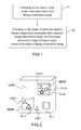
figure 1 , the computer-implemented method for designing an assembly of objects in a three-dimensional scene of a system of computer-aided design, comprises: - a first step S1 providing, in the scene, a first locator associated with a first design dimensions range; and
- a second step S2 providing, in the scene, at least one second locator respectively associated with a second design dimensions range, the first design dimensions range having an upper bound greater than the upper bound of the second design dimensions range.
- Then, like illustrated on
figure 2 , to realize a mixed design dimensions ranges assembly, the user needs to incorporate a part into an upper design dimensions range assembly. - This is done by defining in the higher design dimensions range assembly a part containing a locator, for example an axis system, that is used to locate and position the lower dimension part. This mechanism can be repeated as many times as desired: the lower dimension part can define a locator in order to locate and position an even lower dimension part, and so on.
- An axis system can be used as a locator to locate a part which is not from a directly smaller design dimensions range. That means that the axis system in an Extra Large Design dimensions range part can be used to position a Normal or Small Design dimensions range part (not only a Large Design dimensions range part).
- There can be several locators, in the present case several axis systems, if there are several lower dimension parts to be located and assembled with the same part.
- The location is associative. If the locator position changes, the part which is positioned on this locator moves accordingly when it gets updated.
- In the present case of
figure 2 is represented a first locator LOC1 associated with an upper design dimensions range assembly which is the Large Design dimensions range Part LDRP, comprising a first element EL1. - In the described examples, locators, or in other words reference and local(s) frames, comprise a respective axis system, but, alternatively, they can comprise any system for spatial positioning.
- A second locator LOC2 is associated with a Normal Design dimensions range Part NDRP, comprising two second elements EL2a and EL2b, and a third locator LOC3 is associated with a Small Design dimensions range Part SDRP, comprising a third element EL3.
- On
figure 3 is illustrated an example of refinement on the design of a bridge, wherein different second locators are successively nested in a first locator LOC1. - On
figure 3 , the first locator LOC1 is associated with a Extra Large Design dimensions range ELDR, the Earth, and a first second locator LOCI2a associated with a Large Design dimensions range LDR, a bridge, nested in the first locator LOC1, and a second second locator LOCI2b associated with a Normal Design dimensions range NDR, a section of the bridge, nested in the first second locator LOCI2a. - This invention also proposes to transfer a part of the geometry in a given design dimensions range part to a lower or upper design dimensions range part.
- When the transfer occurs to a lower design dimensions range part, the geometry is clipped to fit into the lower design dimensions range part. The geometry might also need to be cleaned if there are some gaps in the geometry that would have to be filled to get a clean and valid geometry (and topology) after transfer.
-
Figures 4 to 9 illustrate an example of the method according to an aspect of the invention. - The user can start from a first locator LOC1 associated with a Large Design dimensions range Part LDRP to make the conceptual design of a bridge, like illustrated on
figure 4 . - Then, like illustrated on
figure 5 , the user can define two second locators LOC2a and LOC2b, to locate a position two corresponding Normal Design dimensions ranges Parts NDRPa and NDRPb, and onfigure 6 the user can create and position the two corresponding Normal Design dimensions ranges Parts NDRPa and NDRPb. - The two Normal Design dimensions ranges Parts NDRPa and NDRPb are then empty.
- On
figure 7 is illustrated an Import (or transfer) of skeleton data from the large dimension part. The data are clipped and cleaned if necessary during import. Import mechanism works on any type of geometry (wireframe, surface, solid, mesh...) and is also associative. - On
figure 8 , the design is finally completed in the two Normal Design dimensions ranges Parts NDRPa and NDRPb. - Then, on
figure 9 is represented an assembly of a large design dimensions range part LDRP and normal design dimensions ranges parts NDRPa and NDRPb. - In this method, everything is intended to be associative, the positioning of the lower dimensions parts on their axis system, and the geometry transfer from one part to another part. That makes this method very easy to automate and the changes very easy to apply.
- Conversely, when transferring geometry to an upper dimension part, the geometry is cleaned so that the too small entities (the ones smaller than the precision of the upper dimension part) are removed from the resulting geometry.
- For example, the design dimensions ranges are selectable in a predefined list.
- Furthermore, the first design dimensions range is adapted to fit the biggest object of the assembly.
- The first design dimensions range can be as small as possible.
-
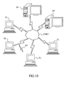
Figure 10 illustrates a computer network or similar digital processing environment in which the present invention may be implemented. - Client computer(s)/devices CL and server computer(s) SV provide processing, storage, and input/output devices executing application programs and the like. Client computer(s)/devices CL can also be linked through communications network CNET to other computing devices, including other client devices/processes CL and server computer(s) SV. Communications network 70 can be part of a remote access network, a global network (e.g., the Internet), a worldwide collection of computers, Local area or Wide area networks, and gateways that currently use respective protocols (TCP/IP, Bluetooth, etc.) to communicate with one another. Other electronic device/computer network architectures are suitable.
-
Figure 11 is a diagram of the internal structure of a computer (e.g., client processor/device CL or server computers SV) in the computer system offigure 10 . Each computer CL, SV contains system bus SB, where a bus is a set of hardware lines used for data transfer among the components of a computer or processing system. Bus SB is essentially a shared conduit that connects different elements of a computer system (e.g., processor, disk storage, memory, input/output ports, network ports, etc...) that enables the transfer of information between the elements. - Attached to system bus SB is I/O device interface DI for connecting various input and output devices (e.g., keyboard, mouse, displays, printers, speakers, etc.) to the computer CL, SV. Network interface NI allows the computer to connect to various other devices attached to a network (e.g., network CNET of
figure 10 ). - Memory MEM provides volatile storage for computer software instructions SI and data CPP used to implement an embodiment of the present invention (e.g., a first path builder PB, means CM for computing a second path, an updater UD implementing the method discussed in
Figs 1 to 8 , and supporting code detailed above). - Disk storage DS provides non-volatile storage for computer software instructions SI and data DAT used to implement an embodiment of the present invention. Central processor unit CPU is also attached to system bus SB and provides for the execution of computer instructions.
- In one embodiment, the processor routines SI and data DAT are a computer program product (generally referenced CPP), including a computer readable medium (e.g., a removable storage medium such as one or more DVD-ROM's, CD-ROM's, diskettes, tapes, etc...) that provides at least a portion of the software instructions for the invention system. Computer program product CPP can be installed by any suitable software installation procedure, as is well known in the art.
- In another embodiment, at least a portion of the software instructions may also be downloaded over a cable, communication and/or wireless connection. In other embodiments, the invention programs are a computer program propagated signal product SP embodied on a propagated signal on a propagation medium (e.g., a radio wave, an infrared wave, a laser wave, a sound wave, or an electrical wave propagated over a global network such as the Internet, or other network(s)). Such carrier medium or signals provide at least a portion of the software instructions for the present invention routines/program CPP.
- In alternate embodiments, the propagated signal is an analog carrier wave or digital signal carried on the propagated medium. For example, the propagated signal may be a digitized signal propagated over a global network (e.g., the Internet), a telecommunications network, or other network.
- In one embodiment, the propagated signal is a signal that is transmitted over the propagation medium over a period of time, such as the instructions for a software application sent in packets over a network over a period of milliseconds, seconds, minutes, or longer.
- In another embodiment, the computer readable medium of computer program product CPP is a propagation medium that the computer system CL may receive and read, such as by receiving the propagation medium and identifying a propagated signal embodied in the propagation medium, as described above for computer program propagated signal product.
- Generally speaking, the term "carrier medium" or transient carrier encompasses the foregoing transient signals, propagated signals, propagated medium, storage medium and the like.
- While this invention has been particularly shown and described with references to example embodiments thereof, it will be understood by those skilled in the art that various changes in form and details may be made therein without departing from the scope of the invention encompassed by the appended claims.
Claims (10)
- A computer-implemented method for designing an assembly of objects in a three-dimensional scene of a system of computer-aided design, comprising the steps of:- providing (S1), in the scene, a first locator (LOC1) associated with a first design dimensions range; and- providing (S2), in the scene, at least one second locator (LOC2a, LOC2b) respectively associated with a second design dimensions range, the first design dimensions range having an upper bound greater than the upper bound of the second design dimensions range.
- Method according to claim 1, wherein each locator (LOC1, LOC2a, LOC2b) comprises an axis system.
- Method according to claim 1 or 2, wherein a second locator (LOC2a, LOC2b) is positioned relative to the first locator (LOC1).
- Method according to anyone of claim 1 to 3, wherein different second locators (LOCI2a, LOCI2b) are successively nested.
- Method according to anyone of preceding claims, wherein the design dimensions ranges are selectable in a predefined list.
- Method according to anyone of preceding claims, wherein the first design dimensions range is automatically adapted to fit the biggest object of the assembly.
- Method according to claim 6, wherein the first design dimensions range is as small as possible.
- A computer-readable medium having computer-executable instructions to cause the computer system to perform the method for designing an assembly of objects in a three-dimensional scene of anyone of claims 1 to 7.
- A computer program product, stored on a computer readable medium, for designing an assembly of objects in a three-dimensional scene, comprising code means for causing the system to take the steps of anyone of claims 1 to 7.
- An apparatus for designing an assembly of objects in a three-dimensional scene of a computer-aided system comprising means for implementing the steps of the method of anyone of claims 1 to 7.
Priority Applications (6)
| Application Number | Priority Date | Filing Date | Title |
|---|---|---|---|
| EP13305124.3A EP2763061A1 (en) | 2013-02-01 | 2013-02-01 | Computer-implemented method for designing an assembly of objects in a three-dimensional scene of a system of computer-aided design |
| US14/163,904 US10496761B2 (en) | 2013-02-01 | 2014-01-24 | Computer-implemented method for designing an assembly of objects in a three-dimensional scene of a system of computer-aided design |
| JP2014013475A JP6605785B2 (en) | 2013-02-01 | 2014-01-28 | A computer-implemented method for designing an assembly of objects in a three-dimensional scene of a computer-aided design (hereinafter "CAD") system |
| KR1020140011309A KR20140099211A (en) | 2013-02-01 | 2014-01-29 | A computer-implemented method for designing an assembly of objects in a three-dimensional scene of a system of computer-aided design |
| CN201410107879.XA CN104008224B (en) | 2013-02-01 | 2014-01-30 | Method, medium and apparatus for designing an assembly of objects in a three-dimensional scene |
| CA2841673A CA2841673A1 (en) | 2013-02-01 | 2014-01-31 | A computer-implemented method for designing an assembly of objects in a three-dimensional scene of a system of computer-aided design |
Applications Claiming Priority (1)
| Application Number | Priority Date | Filing Date | Title |
|---|---|---|---|
| EP13305124.3A EP2763061A1 (en) | 2013-02-01 | 2013-02-01 | Computer-implemented method for designing an assembly of objects in a three-dimensional scene of a system of computer-aided design |
Publications (1)
| Publication Number | Publication Date |
|---|---|
| EP2763061A1 true EP2763061A1 (en) | 2014-08-06 |
Family
ID=47757527
Family Applications (1)
| Application Number | Title | Priority Date | Filing Date |
|---|---|---|---|
| EP13305124.3A Ceased EP2763061A1 (en) | 2013-02-01 | 2013-02-01 | Computer-implemented method for designing an assembly of objects in a three-dimensional scene of a system of computer-aided design |
Country Status (6)
| Country | Link |
|---|---|
| US (1) | US10496761B2 (en) |
| EP (1) | EP2763061A1 (en) |
| JP (1) | JP6605785B2 (en) |
| KR (1) | KR20140099211A (en) |
| CN (1) | CN104008224B (en) |
| CA (1) | CA2841673A1 (en) |
Families Citing this family (1)
| Publication number | Priority date | Publication date | Assignee | Title |
|---|---|---|---|---|
| CN110502819B (en) * | 2019-08-14 | 2023-03-31 | 上海市城市建设设计研究总院(集团)有限公司 | Computer aided design method for external closed stirrup of concrete bridge strip-shaped member |
Family Cites Families (9)
| Publication number | Priority date | Publication date | Assignee | Title |
|---|---|---|---|---|
| JP3361652B2 (en) | 1994-04-25 | 2003-01-07 | 富士通株式会社 | 3D figure arrangement input method and graphic system |
| JP2004529378A (en) | 2001-03-08 | 2004-09-24 | ニューメリカル テクノロジーズ インコーポレイテッド | Alternating phase shift masking for multi-level masking resolution |
| US7567850B2 (en) | 2003-06-03 | 2009-07-28 | Toyota Jidosha Kabushiki Kaisha | Method and system for creating a product parts catalog |
| JP2006134251A (en) | 2004-11-09 | 2006-05-25 | Ricoh Co Ltd | 3D graphic layout input device |
| JP2007207046A (en) | 2006-02-02 | 2007-08-16 | Ricoh Co Ltd | Assembly configuration editing apparatus, assembly configuration editing method, program, and recording medium |
| JP2009110100A (en) | 2007-10-26 | 2009-05-21 | Toshiba Corp | CAD system and component placement method |
| US8462147B2 (en) * | 2009-09-15 | 2013-06-11 | Microsoft Corporation | Mega-mesh sculpting for environments |
| CN102779175B (en) | 2012-06-26 | 2014-12-10 | 北京尔宜居科技有限责任公司 | Method for processing image in CAD (Computer Aided Design) format by using data in XML (Extensive Makeup Language) format |
| US20140046634A1 (en) * | 2012-08-13 | 2014-02-13 | Caterpillar Inc. | Facility Design and Management Systems Using Order Processing |
-
2013
- 2013-02-01 EP EP13305124.3A patent/EP2763061A1/en not_active Ceased
-
2014
- 2014-01-24 US US14/163,904 patent/US10496761B2/en active Active
- 2014-01-28 JP JP2014013475A patent/JP6605785B2/en active Active
- 2014-01-29 KR KR1020140011309A patent/KR20140099211A/en not_active Ceased
- 2014-01-30 CN CN201410107879.XA patent/CN104008224B/en active Active
- 2014-01-31 CA CA2841673A patent/CA2841673A1/en not_active Abandoned
Non-Patent Citations (3)
| Title |
|---|
| CHRISTOPH STAHL ET AL: "Taking Location Modelling to New Levels: A Map Modelling Toolkit for Intelligent Environments", 1 January 2006, LOCATION- AND CONTEXT-AWARENESS LECTURE NOTES IN COMPUTER SCIENCE;;LNCS, SPRINGER, BERLIN, DE, PAGE(S) 74 - 85, ISBN: 978-3-540-34150-5, XP019032563 * |
| DUTTON G: "IMPROVING LOCATIONAL SPECIFICITY OF MAP DATA-A MULTI-RESOLUTION, METADATA-DRIVEN APPROACH AND NOTATION", INTERNATIONAL JOURNAL OF GEOGRAPHICAL INFORMATION SYSTEMS, LONDON, GB, vol. 10, no. 3, 1 January 1996 (1996-01-01), pages 253 - 268, XP008030693, ISSN: 0269-3798, DOI: 10.1080/026937996138034 * |
| GERHARD GRGER ET AL: "CityGML Interoperable semantic 3D city models", ISPRS JOURNAL OF PHOTOGRAMMETRY AND REMOTE SENSING, AMSTERDAM [U.A.] : ELSEVIER, AMSTERDAM, NL, vol. 71, 23 April 2012 (2012-04-23), pages 12 - 33, XP028399395, ISSN: 0924-2716, [retrieved on 20120504], DOI: 10.1016/J.ISPRSJPRS.2012.04.004 * |
Also Published As
| Publication number | Publication date |
|---|---|
| CA2841673A1 (en) | 2014-08-01 |
| KR20140099211A (en) | 2014-08-11 |
| CN104008224A (en) | 2014-08-27 |
| US10496761B2 (en) | 2019-12-03 |
| US20140222388A1 (en) | 2014-08-07 |
| CN104008224B (en) | 2020-08-18 |
| JP2014149827A (en) | 2014-08-21 |
| JP6605785B2 (en) | 2019-11-13 |
Similar Documents
| Publication | Publication Date | Title |
|---|---|---|
| Krämer et al. | A case study on 3D geospatial applications in the web using state-of-the-art WebGL frameworks | |
| CN111243085B (en) | Training method and device for image reconstruction network model and electronic equipment | |
| CN112598762A (en) | Three-dimensional lane line information generation method, device, electronic device, and medium | |
| JP7525256B2 (en) | Adaptive Compression of Simulation Data for Visualization | |
| CN104299271A (en) | A computer-implemented method for determining at least one exploded path of an exploded view of an assembly of three-dimensional modeled objects | |
| Abad et al. | Fourth‐and Fifth‐Order Methods for Solving Nonlinear Systems of Equations: An Application to the Global Positioning System | |
| Ishii et al. | Solving PDEs in space-time: 4D tree-based adaptivity, mesh-free and matrix-free approaches | |
| CN106777302B (en) | Method and device for converting space geographic coordinates | |
| EP2800020B1 (en) | A computer-implemented method for manipulating three-dimensional modeled objects of an assembly in a three-dimensional scene. | |
| US10025754B2 (en) | Linear FE system solver with dynamic multi-grip precision | |
| EP4535217A1 (en) | Systems and methods for determining wear | |
| CN118070699A (en) | Fluid simulation system and equipment | |
| CN114067030A (en) | Dynamic fluid effect processing method and device, electronic equipment and readable medium | |
| US10496761B2 (en) | Computer-implemented method for designing an assembly of objects in a three-dimensional scene of a system of computer-aided design | |
| EP2800064B1 (en) | A computer-implemented method for manipulating three-dimensional modeled objects of an assembly in a three-dimensional scene | |
| WO2019074856A1 (en) | Computerized rendering of animated objects using polynomial particle-in-cell method | |
| CN114663553A (en) | Special effect video generation method, device and equipment and storage medium | |
| CN113705025A (en) | Information extraction and transmission method and device, electronic equipment and computer readable medium | |
| Torguet et al. | Cavalcade: A system for collaborative prototyping | |
| CN115222854A (en) | Virtual image collision processing method and device, electronic equipment and storage medium | |
| KR101967587B1 (en) | Method and apparadus for generating surveying data using task screen providing overlapped layers of construction map data, map data from external map service, and public map data | |
| US8365117B2 (en) | Solutions for on-chip modeling of open termination of fringe capacitance | |
| De Grande et al. | A modular distributed simulation‐based architecture for intelligent transportation systems | |
| US7702494B1 (en) | Method and system for prescribing rigid body orientations in finite element analysis | |
| CN111275813B (en) | Data processing method and device and electronic equipment |
Legal Events
| Date | Code | Title | Description |
|---|---|---|---|
| PUAI | Public reference made under article 153(3) epc to a published international application that has entered the european phase |
Free format text: ORIGINAL CODE: 0009012 |
|
| 17P | Request for examination filed |
Effective date: 20130201 |
|
| AK | Designated contracting states |
Kind code of ref document: A1 Designated state(s): AL AT BE BG CH CY CZ DE DK EE ES FI FR GB GR HR HU IE IS IT LI LT LU LV MC MK MT NL NO PL PT RO RS SE SI SK SM TR |
|
| AX | Request for extension of the european patent |
Extension state: BA ME |
|
| R17P | Request for examination filed (corrected) |
Effective date: 20150203 |
|
| RBV | Designated contracting states (corrected) |
Designated state(s): AL AT BE BG CH CY CZ DE DK EE ES FI FR GB GR HR HU IE IS IT LI LT LU LV MC MK MT NL NO PL PT RO RS SE SI SK SM TR |
|
| STAA | Information on the status of an ep patent application or granted ep patent |
Free format text: STATUS: EXAMINATION IS IN PROGRESS |
|
| 17Q | First examination report despatched |
Effective date: 20180618 |
|
| APBK | Appeal reference recorded |
Free format text: ORIGINAL CODE: EPIDOSNREFNE |
|
| APBN | Date of receipt of notice of appeal recorded |
Free format text: ORIGINAL CODE: EPIDOSNNOA2E |
|
| APBR | Date of receipt of statement of grounds of appeal recorded |
Free format text: ORIGINAL CODE: EPIDOSNNOA3E |
|
| APAF | Appeal reference modified |
Free format text: ORIGINAL CODE: EPIDOSCREFNE |
|
| APBT | Appeal procedure closed |
Free format text: ORIGINAL CODE: EPIDOSNNOA9E |
|
| STAA | Information on the status of an ep patent application or granted ep patent |
Free format text: STATUS: THE APPLICATION HAS BEEN REFUSED |
|
| 18R | Application refused |
Effective date: 20230927 |